EP3872588A1 - Nc program conversion processing method and computer for conversion - Google Patents
Nc program conversion processing method and computer for conversion Download PDFInfo
- Publication number
- EP3872588A1 EP3872588A1 EP19876760.0A EP19876760A EP3872588A1 EP 3872588 A1 EP3872588 A1 EP 3872588A1 EP 19876760 A EP19876760 A EP 19876760A EP 3872588 A1 EP3872588 A1 EP 3872588A1
- Authority
- EP
- European Patent Office
- Prior art keywords
- tool
- block
- path
- conversion
- program
- Prior art date
- Legal status (The legal status is an assumption and is not a legal conclusion. Google has not performed a legal analysis and makes no representation as to the accuracy of the status listed.)
- Granted
Links
Images


Classifications
-
- G—PHYSICS
- G05—CONTROLLING; REGULATING
- G05B—CONTROL OR REGULATING SYSTEMS IN GENERAL; FUNCTIONAL ELEMENTS OF SUCH SYSTEMS; MONITORING OR TESTING ARRANGEMENTS FOR SUCH SYSTEMS OR ELEMENTS
- G05B19/00—Program-control systems
- G05B19/02—Program-control systems electric
- G05B19/18—Numerical control [NC], i.e. automatically operating machines, in particular machine tools, e.g. in a manufacturing environment, so as to execute positioning, movement or co-ordinated operations by means of program data in numerical form
- G05B19/408—Numerical control [NC], i.e. automatically operating machines, in particular machine tools, e.g. in a manufacturing environment, so as to execute positioning, movement or co-ordinated operations by means of program data in numerical form characterised by data handling or data format, e.g. reading, buffering or conversion of data
- G05B19/4083—Adapting program, configuration
-
- G—PHYSICS
- G05—CONTROLLING; REGULATING
- G05B—CONTROL OR REGULATING SYSTEMS IN GENERAL; FUNCTIONAL ELEMENTS OF SUCH SYSTEMS; MONITORING OR TESTING ARRANGEMENTS FOR SUCH SYSTEMS OR ELEMENTS
- G05B19/00—Program-control systems
- G05B19/02—Program-control systems electric
- G05B19/18—Numerical control [NC], i.e. automatically operating machines, in particular machine tools, e.g. in a manufacturing environment, so as to execute positioning, movement or co-ordinated operations by means of program data in numerical form
- G05B19/402—Numerical control [NC], i.e. automatically operating machines, in particular machine tools, e.g. in a manufacturing environment, so as to execute positioning, movement or co-ordinated operations by means of program data in numerical form characterised by control arrangements for positioning, e.g. centring a tool relative to a hole in the workpiece, additional detection means to correct position
-
- G—PHYSICS
- G05—CONTROLLING; REGULATING
- G05B—CONTROL OR REGULATING SYSTEMS IN GENERAL; FUNCTIONAL ELEMENTS OF SUCH SYSTEMS; MONITORING OR TESTING ARRANGEMENTS FOR SUCH SYSTEMS OR ELEMENTS
- G05B19/00—Program-control systems
- G05B19/02—Program-control systems electric
- G05B19/18—Numerical control [NC], i.e. automatically operating machines, in particular machine tools, e.g. in a manufacturing environment, so as to execute positioning, movement or co-ordinated operations by means of program data in numerical form
- G05B19/19—Numerical control [NC], i.e. automatically operating machines, in particular machine tools, e.g. in a manufacturing environment, so as to execute positioning, movement or co-ordinated operations by means of program data in numerical form characterised by positioning or contouring control systems, e.g. to control position from one programmed point to another or to control movement along a programmed continuous path
- G05B19/21—Numerical control [NC], i.e. automatically operating machines, in particular machine tools, e.g. in a manufacturing environment, so as to execute positioning, movement or co-ordinated operations by means of program data in numerical form characterised by positioning or contouring control systems, e.g. to control position from one programmed point to another or to control movement along a programmed continuous path using an incremental digital measuring device
- G05B19/25—Numerical control [NC], i.e. automatically operating machines, in particular machine tools, e.g. in a manufacturing environment, so as to execute positioning, movement or co-ordinated operations by means of program data in numerical form characterised by positioning or contouring control systems, e.g. to control position from one programmed point to another or to control movement along a programmed continuous path using an incremental digital measuring device for continuous-path control
-
- G—PHYSICS
- G05—CONTROLLING; REGULATING
- G05B—CONTROL OR REGULATING SYSTEMS IN GENERAL; FUNCTIONAL ELEMENTS OF SUCH SYSTEMS; MONITORING OR TESTING ARRANGEMENTS FOR SUCH SYSTEMS OR ELEMENTS
- G05B19/00—Program-control systems
- G05B19/02—Program-control systems electric
- G05B19/18—Numerical control [NC], i.e. automatically operating machines, in particular machine tools, e.g. in a manufacturing environment, so as to execute positioning, movement or co-ordinated operations by means of program data in numerical form
- G05B19/408—Numerical control [NC], i.e. automatically operating machines, in particular machine tools, e.g. in a manufacturing environment, so as to execute positioning, movement or co-ordinated operations by means of program data in numerical form characterised by data handling or data format, e.g. reading, buffering or conversion of data
- G05B19/4086—Coordinate conversions; Other special calculations
-
- G—PHYSICS
- G05—CONTROLLING; REGULATING
- G05B—CONTROL OR REGULATING SYSTEMS IN GENERAL; FUNCTIONAL ELEMENTS OF SUCH SYSTEMS; MONITORING OR TESTING ARRANGEMENTS FOR SUCH SYSTEMS OR ELEMENTS
- G05B19/00—Program-control systems
- G05B19/02—Program-control systems electric
- G05B19/18—Numerical control [NC], i.e. automatically operating machines, in particular machine tools, e.g. in a manufacturing environment, so as to execute positioning, movement or co-ordinated operations by means of program data in numerical form
- G05B19/4093—Numerical control [NC], i.e. automatically operating machines, in particular machine tools, e.g. in a manufacturing environment, so as to execute positioning, movement or co-ordinated operations by means of program data in numerical form characterised by part programming, e.g. entry of geometrical information as taken from a technical drawing, combining this with machining and material information to obtain control information, named part program, for the NC machine
- G05B19/40937—Numerical control [NC], i.e. automatically operating machines, in particular machine tools, e.g. in a manufacturing environment, so as to execute positioning, movement or co-ordinated operations by means of program data in numerical form characterised by part programming, e.g. entry of geometrical information as taken from a technical drawing, combining this with machining and material information to obtain control information, named part program, for the NC machine concerning programming of machining or material parameters, pocket machining
-
- G—PHYSICS
- G05—CONTROLLING; REGULATING
- G05B—CONTROL OR REGULATING SYSTEMS IN GENERAL; FUNCTIONAL ELEMENTS OF SUCH SYSTEMS; MONITORING OR TESTING ARRANGEMENTS FOR SUCH SYSTEMS OR ELEMENTS
- G05B2219/00—Program-control systems
- G05B2219/30—Nc systems
- G05B2219/34—Director, elements to supervisory
- G05B2219/34093—Real time toolpath generation, no need for large memory to store values
-
- G—PHYSICS
- G05—CONTROLLING; REGULATING
- G05B—CONTROL OR REGULATING SYSTEMS IN GENERAL; FUNCTIONAL ELEMENTS OF SUCH SYSTEMS; MONITORING OR TESTING ARRANGEMENTS FOR SUCH SYSTEMS OR ELEMENTS
- G05B2219/00—Program-control systems
- G05B2219/30—Nc systems
- G05B2219/36—Nc in input of data, input key till input tape
- G05B2219/36043—Correction or modification of program
-
- G—PHYSICS
- G05—CONTROLLING; REGULATING
- G05B—CONTROL OR REGULATING SYSTEMS IN GENERAL; FUNCTIONAL ELEMENTS OF SUCH SYSTEMS; MONITORING OR TESTING ARRANGEMENTS FOR SUCH SYSTEMS OR ELEMENTS
- G05B2219/00—Program-control systems
- G05B2219/30—Nc systems
- G05B2219/36—Nc in input of data, input key till input tape
- G05B2219/36232—Before machining, convert, adapt program to specific possibilities of machine
-
- G—PHYSICS
- G05—CONTROLLING; REGULATING
- G05B—CONTROL OR REGULATING SYSTEMS IN GENERAL; FUNCTIONAL ELEMENTS OF SUCH SYSTEMS; MONITORING OR TESTING ARRANGEMENTS FOR SUCH SYSTEMS OR ELEMENTS
- G05B2219/00—Program-control systems
- G05B2219/30—Nc systems
- G05B2219/36—Nc in input of data, input key till input tape
- G05B2219/36237—Prepare nc program for selected, distinct nc machines
-
- G—PHYSICS
- G05—CONTROLLING; REGULATING
- G05B—CONTROL OR REGULATING SYSTEMS IN GENERAL; FUNCTIONAL ELEMENTS OF SUCH SYSTEMS; MONITORING OR TESTING ARRANGEMENTS FOR SUCH SYSTEMS OR ELEMENTS
- G05B2219/00—Program-control systems
- G05B2219/30—Nc systems
- G05B2219/36—Nc in input of data, input key till input tape
- G05B2219/36407—Follow path with probe, store deviations for correction during normal operation
Definitions
- the present invention relates to a technique for converting an NC program for numerical control (NC).
- a workpiece (hereinafter sometimes referred to as a workpiece) may be processed by inputting an NC program to an NC machine tool.
- JP-A-2003-263208 discloses "The NC program apparatus 1 replaces the machining shape required for the workpiece 5 with a predetermined fixed machining cycle according to the designation of machining conditions including the machining start point, machining end point, and size of the end mill E to be used, repeats the calculation of the predicted value of the cutting resistance applied to the end mill E that is fed and moved along the assumed feed route in the fixed machining cycle until a predetermined comparative evaluation result is obtained with a predetermined appropriate value, and determines the feed route of the end mill E along with the feed rate in each part.”
- the present invention has been made in view of the above circumstances and an object thereof is to provide a technique for converting an NC program to an NC program capable of ensuring appropriate precision in working while avoiding the occurrence of differences in levels caused by the correction during the cutting of a cut surface of a workpiece.
- the NC program conversion processing method is an NC program conversion processing method that converts a pre-correction NC program and generates a post-correction NC program, and identifies a contactless portion tool path, which is a path on which a tool of a work machine executing the pre-correction NC program does not come in to contact with a workpiece during the processes corresponding to the blocks, based on a plurality of blocks in the pre-correction NC program; identifies contactless blocks, which are the blocks having only the contactless portion tool path as a path; determines the tool route correction quantity in the tool radial direction in a work process of the workpiece according to the following blocks, which are one or more of the blocks following the contactless block; and creates blocks including descriptions for correcting the tool path by the tool route correction quantity, before the following blocks.
- an NC program can be converted into an NC program capable of ensuring appropriate precision in working.
- Fig. 1 is an overall configuration diagram of a work process system according to an embodiment.
- the work process system 1 includes a conversion use computer 10, a plurality of NC machine tools 20 (an example of a work machine), and a plurality of on-site use computers 30.
- the conversion use computer 10, the plurality of NC machine tools 20, and the plurality of on-site use computers 30 are connected via a network 40.
- the network 40 may be a wired network or a wireless network.
- the NC machine tool 20 and the on-site use computer 30 are arranged at each of a place A and a place B, and the conversion use computer 10 is arranged at a place C.
- the conversion use computer 10 may be arranged at either the place A or the place B.
- the plurality of NC machine tools 20 and the plurality of on-site use computers 30 may be arranged at the same place.
- the conversion use computer 10 executes the process of converting an NC program for a certain NC machine tool 20 (conversion source NC program: pre-correction NC program) into an NC program for another NC machine tool 20 (conversion result NC program: post-correction NC program). The details of the conversion use computer 10 will be described later.
- the on-site use computer 30 is a computer operated by an on-site operator and is composed of, for example, a personal computer (PC) including a processor, storage resources, and the like.
- the on-site referred to here is typically a place where the NC machine tool 20 is installed (for example, in a factory, a building, a floor, or the like) in Fig. 1 .
- the on-site use computer 30 may be used at a place other than the place where the NC machine tool 20 is installed.
- the following description describes an example in which the on-site use computer 30 is in charge of the download process and screen display of the post-conversion NC program, the screen display of the conversion input screen, and the like, and the conversion use computer 10 is in charge of the actual conversion process.
- the conversion use computer 10 may be composed of a plurality of computers. Therefore, in the following description, the term "conversion system" may be used.
- the system includes one or more computers (on-site use computer 30 or conversion use computer 10) and is a system that performs the processes described below that the conversion use computer 10 and the on-site use computer 30 are in charge of. A part of the processing realized by the on-site use computer 30 may be omitted.
- the NC machine tool 20 is, for example, a machining center and includes a main body 22 that executes the work process, an NC controller 21 that controls the work process of the main body 22, and a tool magazine 25 as an example of an accommodating unit capable of accommodating tools TL including one or more toolsets to be used in the main body 22.
- the tool magazine 25 includes a plurality of slots (SL: 25a, 25b, and 25c) each capable of accommodating one tool TL.
- the NC controller 21 controls the work process of the main body 22 and the tool changing process according to the NC program stored inside.
- the main body 22 includes a processing head unit 23, a stage 24, and a tool change unit 26 as an example of an exchange unit.
- the processing head unit 23 includes a rotatable spindle on which a tool TL can be mounted.
- the processing head unit 23 may be the spindle itself.
- the stage 24 is movable on which the workpiece (workpiece) W, which is the target of the work process, is placed.
- the tool change unit 26 removes the tool TL from the processing head unit 23 and accommodates the tool TL in an empty slot of the tool magazine 25.
- the tool change unit 26 takes out a tool TL from the slot of the tool magazine 25 and mounts the tool TL to the processing head unit 23.
- An example of the tool change unit 26 is a change arm (also referred to as an ATC arm) of an automatic tool changer (ATC).
- the tool magazine 25 described above is also a component of the automatic tool changer.
- the NC program can internally describe a series of commands (in the NC program terminology, referred to as a code or a word in which parameters are added to the code) meaning a tool change command, and the tool change command includes a slot number that indicates the location of the slot (meaning will be described later) in the tool magazine 25.
- the tool change unit 26 takes out the tool TL from the slot specified by the slot number included in the parameter of the tool change command according to the instruction of the NC controller 21 that has read the tool change command and attaches the tool TL to the processing head unit 23.
- the number of tools TL that can be accommodated in the tool magazine 25 is limited, but various work processes can be supported by preparing one or more toolsets 50 in advance and replacing the toolset accommodated in the tool magazine 25 according to the work process to be executed.
- the tool TL includes a blade unit TLa such as an end mill, a drill, and a cutting tool for cutting the workpiece W, and a holder TLb for mounting the blade unit TLa on the processing head unit 23.
- a blade unit TLa such as an end mill, a drill, and a cutting tool for cutting the workpiece W
- a holder TLb for mounting the blade unit TLa on the processing head unit 23.
- the holder TLb may not be included and at least the blade unit TLa only needs to be included.
- the entity including at least a work machine that has performed the machining using an NC program to be converted (that is, a conversion source NC program) and a toolset corresponding to the work machine will be sometimes referred to as a "conversion source environment”.
- the entity including at least a work machine scheduled to perform the machining using a post-conversion NC program (that is, a conversion result NC program) and a toolset corresponding to the work machine will be sometimes referred to as a "conversion result environment”.
- a physical or logical entity included in each place for example, the temperature, temperature sensor, humidity, humidity sensor of the place, or the floor where the work machine is installed in the place, the building that makes up the place
- the "toolset corresponding to the work machine” includes a toolset stored in the tool magazine of the work machine and a toolset that may be stored and used in the tool magazine in the future.
- the toolset corresponding to the work machine is typically installed in the same place as the work machine.
- Fig. 2 is a configuration diagram of a conversion use computer according to an embodiment.
- the conversion use computer 10 is, for example, a personal computer or a general-purpose computer.
- the conversion use computer 10 includes a CPU 11 as an example of a processor, a network interface 12 (abbreviated as Net I/F in the drawing), a user interface 13 (User I/F in the drawing), a storage resource 14 as an example of a storage unit, and an internal network that connects these configurations.
- the CPU 11 can execute the program stored in the storage resource 14.
- the storage resource 14 stores a program to be executed by the CPU 11, various information used in this program, an NC program used by the NC machine tool 20, and the like.
- the storage resource 14 may be, for example, a semiconductor memory, a flash memory, a hard disk drive (HDD), a solid state drive (SSD), or the like, and may be a volatile memory or a non-volatile memory.
- the network interface 12 is an interface for communicating with an external device (for example, the on-site use computer 30, the NC controller 21 of the NC machine tool 20, and the like) via the network 40.
- an external device for example, the on-site use computer 30, the NC controller 21 of the NC machine tool 20, and the like
- the user interface 13 is, for example, a touch panel, a display, a keyboard, a mouse, or the like, but may be another device as long as operations from an operator (user) can be received and information can be displayed.
- the user interface 13 may be composed of these multiple devices.
- the storage resource 14 stores work machine configuration information 1421, toolset information 1422, individual tool information 1423, conversion source NC program 1424, conversion result NC program 1425, and conversion history information 1426.
- the storage resource 14 may store other information. The details of each data and program are described from the next paragraph. Each information or some items of each information may be omitted.
- Work machine configuration information 1421 is configured as, for example, a table that stores information related to each NC machine tool 20.
- the work machine configuration information 1421 includes each information shown below for each NC machine tool 20.
- the information of (a1), (a2), (a4), (a5), (a8), (a9), and (a10) is acquired from, for example, the NC controller 21 of the NC machine tool 20.
- (a3), (a6), (a7), and (a11) are acquired from the input information by the operator.
- the method of acquiring information is not limited thereto, and at least a part of (a1), (a2), (a4), (a5), (a8), (a9), and (a10) may be acquired from the input information by the operator via the user interface 13, and among (a3), (a6), (a7), and (a11), the information that can be acquired from the NC controller 21 may be acquired from the NC controller 21.
- the information acquired from the NC controller 21 may also be acquired from an alternative device (for example, another computer or the sensor itself). * Tool information (toolset information 1422 and individual tool information 1423)
- the toolset information 1422 is information for managing a group (set) composed of one or more tools TL.
- the toolset information 1422 is a set including toolset identification information (toolset ID), identifiers of one or more tools TL constituting the set, or model numbers.
- the individual tool information 1423 is information related to each tool.
- the individual tool information 1423 includes each information shown below.
- the information (b1) to (b4) is acquired from, for example, input information by the operator via the user interface 13, but information that can be acquired from the NC controller 21 may be acquired from the NC controller 21.
- the following information may be stored in the storage resource 14.
- the conversion program 1411 executes the following processes by being executed by the CPU 11.
- the conversion unit is configured by the CPU 11 executing the conversion program 1411. *
- the conversion program 1411 executes the conversion process of converting the conversion source NC program 1424 to be converted into the conversion result NC program 1425, based on various information input to the conversion input screen 100 by reflecting various information input to the conversion input screen 100 into the work machine configuration information 1421, the toolset information 1422, and the individual tool information 1423, and information of the conversion result environment or the information of the conversion source environment included in the work machine configuration information 1421, the toolset information 1422, and the individual tool information 1423, and stores the obtained conversion result NC program 1425 in the storage resource 14.
- the conversion program 1411 sets the data obtained by changing or adding the command of the conversion source NC program 1424 based on the information related to the rigidity of the conversion result NC machine tool 20 or the rigidity of the tool TL of the toolset 50 used by the conversion result NC machine tool 20, as the conversion result NC program 25.
- the commands to be added or changed include tool diameter compensation, tool length compensation, tool wear compensation, feed rate, or cutting speed, so that a significant change in machining work such as an increase in the number of machining of the workpiece W by the tool TL may be avoided.
- a command for example, a command corresponding to trial cutting that increases the number of machining the workpiece W may be added.
- the conversion program 1411 converts the description of the conversion source NC program for the portion where the description format is different into the description format for the NC controller 21 of the conversion result NC machine tool 20.
- the NC controller 21 of the conversion result NC machine tool 20 can perform the work process without any trouble.
- the conversion program 1411 may describe, as a comment in the conversion result NC program 1425, the work machine ID of the conversion result NC machine tool 20, the model number (or identifier) of each tool TL of the toolset specified to be used in the conversion result NC machine tool 20, and the arrangement location information (slot number) of each tool TL.
- MC2 is a work machine ID
- SL1 is a slot number
- ML7x is a model number of a mill.
- each tool TL specified to be used and the arrangement location information of each tool TL may be described as comments in the conversion result NC program 1425.
- the comment explained here may be referred to as "conversion result device or tool comment”.
- the conversion program 1411 stores the conversion process ID (conversion history ID) as a comment in the conversion result NC program 1425 and stores the conversion history information 1426 in which the conversion history ID and various information input to the conversion input screen 100 are associated with each other in the storage resource 14.
- the conversion process by the conversion program 1411 may be performed multiple times. For example, it is a case where it is desired to further convert the conversion result NC program 1425 converted for the first time for another NC machine tool 20 or toolset. In such a case, the above-mentioned "conversion result device or tool comment” and “history comment” may exist in the conversion result NC program 1425 by the amount of the conversion multiplicity. However, it is preferable to keep only the comments generated by the last conversion and delete the comments before that. Especially in the "conversion result device or tool comment", the only thing the operator should see is the comment given in the last conversion. * After the conversion process, the conversion program 1411 displays a download confirmation screen 200 (see Fig. 4 ) described later, and when a download button 210 is pressed, the conversion result NC program 1425 is transmitted to the on-site use computer 30 at the place where the NC controller 21 of the conversion result NC machine tool 20, or the conversion result NC machine tool 20 is located.
- the configuration information acquisition program 1412 executes the following processes by being executed by the CPU 11.
- the rigidity information receiving unit is configured by the CPU 11 executing the configuration information acquisition program 1412.
- Fig. 3 is a configuration diagram of a conversion input screen according to an embodiment.
- the conversion input screen 100 is, for example, a screen composed of the following description areas and including a screen object for input or display in each area.
- the processing information area 100A includes the following.
- area for display and input is used, but this refers to a screen object for display or an area including a screen object for input.
- File name input area 101 for inputting the file name of the NC program to be converted (conversion source).
- the pre-conversion environment area 100B includes the following.
- the conversion result environment area 100C includes the following.
- the file name input area 101 may be regarded as a part of the pre-conversion environment together with the toolset TL in the conversion source environment and may be included in the pre-processing environment area 100B, or conversely, may be collectively included in the processing information 100A.
- the area for inputting or displaying the above-mentioned "workpiece W information", "other pre-conversion environment information", and "other conversion result environment information” is not shown.
- information input may be accepted or information may be displayed by displaying the areas on the screen.
- the workpiece W information may be included in the area 100A. It is preferable if the information of the workpiece W has a small change in each environment.
- the shape of the workpiece W before machining differs depending on the environment, such an input or display area may be included in the area 100B or the area 100C.
- a screen object for designating a file name in which the shape data is stored may be used as in the area 101 of Fig. 3 .
- the conversion source work machine information input area 103 is an area for inputting information that needs to be input by the operator (conversion source work machine required input information), for example, the above-mentioned information (a6), (a7), and (a11), and for displaying information that has already been acquired and inputting correction information.
- the conversion source tool information input areas 105, 106, and 107 are areas for inputting information that needs to be input by the operator (conversion source tool request input information), for example, the above-mentioned information (b3), and (b4), and for displaying information that has already been acquired and inputting correction information.
- the conversion source tool information input area 105 is an input area corresponding to the tool of TL1 of the conversion source toolset designation area 104
- the conversion source tool information input area 106 is an input area corresponding to the tool of TL2 of the conversion source toolset designation area 104
- the conversion source tool information input area 107 is an input area corresponding to the tool of TL3 of the conversion source toolset designation area 104.
- the conversion result work machine information input area 111 is an area for inputting information that needs to be input by the operator, for example, the above-mentioned information (a6), (a7), and (a11), and for displaying information that has already been acquired and inputting correction information.
- the conversion result tool information input areas 113, 114, and 115 are areas for inputting information that needs to be input by the operator, for example, the above-mentioned information (b3) and (b4), and for displaying information that has already been acquired and inputting correction information.
- the conversion result tool information input area 113 is an input area corresponding to the tool of TL1 of the conversion result toolset designation area 112
- the conversion result tool information input area 114 is an input area corresponding to the tool of TL2 of the conversion result toolset designation area 112
- the conversion result tool information input area 115 is an input area corresponding to the tool of TL3 of the conversion result toolset designation area 112.
- the locations in the conversion result tool information input areas 113, 114, and 115 indicate the location information (slot number) of the tool magazine 25 in which each tool should be placed, but the slot number in which each tool is placed may be set in advance to be the same as the slot number in which the same or similar tools are placed in the conversion result tool information input areas 113, 114, and 115.
- the slot number for arranging each tool the operator may input any slot number. Here, it is necessary to appropriately arrange the corresponding tool in the slot of the input slot number.
- a pull-down button 130 for displaying selection candidates is arranged in the conversion source work machine information input area 103, the conversion source toolset designation area 104, the conversion result work machine designation area 110, the conversion result toolset designation area 112, and the like, and when the pull-down button 130 is pressed, selection candidates in the corresponding area are displayed to be selectable.
- An alert symbol 131 is displayed on the conversion input screen 100 when there is no input in the area where input is required or when the displayed information is information acquired before a predetermined period from the present time. According to the alert symbol 131, the operator can understand that the information is insufficient or out of date and that the operator needs to input necessary information or take additional measurements.
- the user of the screen does not have to input text in the pre-conversion environment area 100B and the conversion result environment area 100C each time conversion is performed.
- the information stored in the storage resource 14 by the conversion use computer 10 may be stored in advance before the display on the screen, the information stored in advance may be displayed on the screen, and the information may be selected on the user interface 13.
- the display on the screen may be omitted for some information related to the pre-conversion environment or the conversion result environment.
- the alert symbol 131 may be displayed in the vicinity of the text displayed inside the areas 102, 104, 110, and 112 (for example, next to the text) to suggest that the information belonging to the work machine or toolset is insufficient or out of date. Based on such a suggestion, the user of the screen can confirm that the items selected before the start of conversion cannot be converted, or even if the items are converted, the precision in working after conversion may decrease, and thus, the present embodiment is more suitable when the conversion process takes time.
- Fig. 4 is a configuration diagram of a download confirmation screen according to an embodiment.
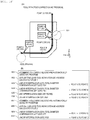
- the download confirmation screen 200 includes a conversion history ID display area 201 that displays a conversion history ID that identifies the executed conversion process, a conversion result work machine information display area 202 that displays the work machine ID and configuration information of the conversion result NC machine tool 20, a conversion result toolset display area 203 that displays the toolset ID of the toolset used in the conversion result NC machine tool 20 and the model number of the tool constituting the toolset, a tool arrangement position display area 204 that displays the arrangement location information (slot number) of each tool in the tool magazine 25 of the conversion result NC machine tool 20, and a download button 210 that accepts an instruction to cause the NC controller 21 of the NC machine tool 20 or the on-site use computer 30 at the conversion result place to download the conversion result NC program 1425.
- a conversion history ID display area 201 that displays a conversion history ID that identifies the executed conversion process
- a conversion result work machine information display area 202 that displays the work machine ID and configuration information of the conversion result NC machine tool 20
- the download confirmation screen 200 the arrangement location information (slot number) of each tool in the tool magazine 25 of the conversion result NC machine tool 20 is displayed, and thus, it is possible to appropriately prevent the tool TL to be used by the operator from being placed in the wrong slot in the tool magazine 25.
- the NC program describes the location information (slot number) of the tool magazine 25 accommodating the tools used in each process. Which tool is to be placed in which slot in the tool magazine 25 can be arbitrarily determined in each NC machine tool 20. Therefore, it is possible that tools for performing the same process between the conversion source NC machine tool 20 and the conversion result NC machine tool 20 are arranged in slots having different numbers in the tool magazine 25.
- the conversion result NC program where the conversion process was performed is used as it is assuming that the slots in the tool magazine 25 of the tool used in the same process in the conversion source and the conversion result have the same number, and thus different types of tools are accommodated in the slots having the same number, there is a concern that completely different tools are used, which may damage the workpiece W or the tool TL. In particular, in a busy season or the like, misplacement of tools is likely to occur and there is a high possibility that such a situation will occur.
- the download confirmation screen 200 the slot number of each tool in the tool magazine 25 of the conversion result NC machine tool 20 is displayed, so that it is possible to prompt the operator to check whether the tool TL to be used has not been placed in the wrong slot, and it is possible to reduce the situation where the tool TL is placed in the wrong slot.
- a download screen such as the screen may be integrated with the screen of Fig. 3 described above. However, when the conversion process takes time, it is preferable that the download screen shown in Fig. 4 can be provided separately from the conversion start button screen shown in Fig. 3 . It is because, after starting the conversion process, the screen user can close the screen and perform another work.
- the advantages of dividing the other screens are as described in the present embodiment.
- the conversion result NC program 1425 when the conversion result NC program 1425 is to be transmitted to the NC controller 21, the conversion result NC program 1425 received by the NC controller 21 is stored, and the conversion result NC program 1425 becomes executable in the subsequent work processes.
- the conversion result NC program 1425 when the conversion result NC program 1425 is to be transmitted to the on-site use computer 30, the on-site use computer 30 stores the conversion result NC program 1425. After that, by storing the conversion result NC program 1425 of the on-site use computer 30 in the NC controller 21 via the network 40 or via a recording medium or the like, the conversion result NC program 1425 becomes executable in the NC controller 21.
- Fig. 5 is a flowchart of the conversion process according to an embodiment.
- the conversion program 1411 reads all the blocks of the conversion source NC program 1424 to be processed with respect to the work area of the memory in the storage resource 14 (S11)
- the block indicates a description portion including a command (address) that can be instructed to the NC machine tool 20 at one time in the work process executed by the conversion source NC program 1424.
- the block contains one or more commands (addresses) that can be instructed at the same time.
- Some addresses include, for example, a code indicating the type of command and parameters related to the content of the command. If the capacity of the conversion source program 1424 is large and all the blocks cannot be called in the work area of the memory, the blocks to be read may be switched according to the progress of the process.
- the conversion program 1411 identifies, based on the read block, one or more paths (referred to as contactless portion tool paths) on which the tool does not come into contact with the workpiece during the process (block process) based on the command indicated by the block (S12). Whether the tool does not come into contact with the workpiece can be identified by simulating the work process based on the shape of the workpiece to be machined and the moving path of the tool in the block.
- all the contactless portion tool paths of the conversion source program 1424 may be identified, or only some contactless portion tool paths may be identified.
- the code in the block is positioning "G00" (JIS B 6314), it basically means that the tool is not in contact with the workpiece, so with respect to the path of the block, it may be determined that the entire path of the block is a contactless portion tool path without further process.
- the conversion program 1411 performs the processing of a loop 1 (S13 to S18) for each of the contactless portion tool paths identified in step S12.
- the initial value of the variable i is 1
- the condition for continuing the processing of the loop 1 is that the variable i is equal to or less than the number of contactless portion tool paths identified in S12, and the variable i is incremented by 1 each time the loop is performed.
- the conversion program 1411 identifies a block (referred to as an identified block) including the contactless portion tool path [i] to be processed (the i-th path among the identified contactless portion tool paths) (S13).
- the conversion program 1411 determines whether the contactless portion tool path [i] is a part of the path of the identified block (S14). As a result, when the contactless portion tool path [i] is not a part of the path of the identified block, that is, when the entire path of the identified block is the contactless portion tool path [i] and the identified block is a contactless block (S14: N), the conversion program 1411 ends the process for the contactless portion tool path [i] without executing the processes of steps S15 to S18.
- the conversion program 1411 executes the process (for example, steps S15 to S17) of dividing the identified block into blocks including a block (for example, a divided contactless block) having at least a part of the contactless portion tool path [i] as a path.
- the conversion program 1411 when the paths of the identified block are a path where the tool comes into contact with the workpiece (contact path), a contactless portion tool path [i], and a contact path in order from the front, the conversion program 1411 generates a block (divided front block) corresponding to the path including the front contact path and the front portion of the contactless portion tool path [i] (S15), generates a block (divided contactless block: divided intermediate block) corresponding to the path only for the intermediate portion of the contactless portion tool path [i] (S16), and generates a block (divided rear block) corresponding to the path including the rear portion of the contactless portion tool path [i] and the rear contact path (S17).
- the conversion program 1411 When the paths of the identified block are a contact path and a contactless portion tool path [i] in order from the front, the conversion program 1411 generates a block (divided front block) corresponding to the path including the contact path and the front portion of the contactless portion tool path [i], and a block (divided contactless block) corresponding to the path of the remaining portion of the contactless portion tool path [i].
- the conversion program 1411 When the paths of the identified block are a contactless portion tool path [i] and a contact path in order from the front, the conversion program 1411 generates a block (divided contactless block) corresponding to the path only for the front portion of the contactless portion tool path [i], and a block (divided rear block) corresponding to the path including the rear portion (remaining portion) of the contactless portion tool path [i] and the rear contact path.
- the same process is performed for each contactless portion tool path by repeating the processing of the loop 1.
- the conversion program 1411 After the process of dividing the identified block is performed (for example, after the execution of S15 to S17), the conversion program 1411 replaces the identified block of the work area of the memory with a plurality of blocks generated by the dividing process (for example, the divided front block, the divided contactless block, and the divided rear block) (S18).
- the conversion program 1411 exits the loop 1 and advances the process to step S19.
- step S19 the conversion program 1411 separates the entire NC program being processed before the contactless block (contactless block or divided contactless block) to identify a plurality of block groups (separated block groups).
- the conversion program 1411 performs the processing of a loop 2 (S20 to S23) for each of the separated block groups identified in step S19.
- the initial value of the variable i is 1, and the condition for continuing the processing of the loop 2 is that the variable i is equal to or less than the number of the separated block groups identified in S19, and the variable i is incremented by 1 each time the loop 1 is performed.
- the conversion program 1411 determines the tool route correction quantity in the tool radial direction of the tool to be used based on the spindle rigidity and the tool rigidity of the conversion result NC machine tool 20 related to the work process in the separated block group [i] to be processed (the i-th block group of the identified separated block group) (S20).
- the calculation may be performed in S20 based on the spindle rigidity and the tool rigidity of the conversion result NC machine tool 20, or the tool route correction quantity calculated in advance may be identified based on the spindle rigidity and the tool rigidity of the conversion result NC machine tool 20.
- the tool route correction quantity may be a tool route correction quantity corresponding to the maximum deflection amount, may be a tool route correction quantity corresponding to the minimum deflection amount, or may be a tool route correction quantity corresponding to an average deflection amount.
- the conversion program 1411 generates a block (correction block) including an address for causing the conversion result NC machine tool 20 to execute the route correction of the determined tool route correction quantity (S21).
- the correction block when executed in the NC machine tool 20, for example, the correction block may be a parameter different from the tool shape parameter on the memory in the NC machine tool 20 and may be used as a block for changing the value of a parameter on the memory that affects a tool diameter compensation address (for example, G41, G42 (JIS B 6314)).
- the tool shape parameter is a parameter that is referred to as a standard when using the tool diameter compensation address and may be manually set by the user, for example.
- the correction block can appropriately prevent the occurrence of such a problem by changing a parameter different from the tool shape parameter.
- the correction block is a notation that designates a parameter different from the tool shape parameter, the user who uses the post-correction NC program can easily visually recognize and grasp the correction block and the tool route correction quantity by the correction block can be easily grasped.
- the conversion program 1411 inserts the generated correction block at the beginning of the separated block group, that is, before the contactless block (S22).
- a block for correction may be created by including the address in which the conversion result NC machine tool 20 executes the route correction by the determined tool route correction quantity in the contactless block without creating a new correction block and without inserting the correction block before the contactless block.
- the conversion program 1411 inserts a comment block indicating that the correction block has been added, before the correction block (comment block) (S23).
- the conversion program 1411 exits the loop 2 and advances the process to step S24.
- step S24 the conversion program 1411 stores all the created blocks in the work area, as the post-conversion NC program (conversion result NC program 1425), in the storage of the storage resource 14.
- Fig. 6 is a diagram showing a shape of a workpiece before the cutting according to an embodiment.
- Fig. 6A shows a top view (XY plan view)
- Fig. 6B shows a side view (YZ plan view)
- Fig. 6C shows a side view (XZ plan view).
- the workpiece 300 Before cutting, the workpiece 300 has a notch 302 partially formed and has a substantially rectangular shape when viewed from above.
- An opening 301 having a columnar hole extending in the Z-axis direction is formed on the negative direction (right direction in Fig. 6A ) side of the workpiece 300 on the Y-axis.
- the height of the workpiece 300 increases along the positive direction of the X-axis.
- Fig. 7 is a diagram showing a target shape of a workpiece after the cutting according to the embodiment.
- Fig. 7A shows a top view (XY plan view)
- Fig. 7B shows a side view (YZ plan view)
- Fig. 7C shows a side view (XZ plan view).
- the target shape of the workpiece 300 after the cutting is such that a stepped unit 303 is formed to be continuous in the vicinity of the negative side of the X-axis and the vicinity of the negative side of the Y-axis with respect to the workpiece 300 before cutting.
- Fig. 8 is a diagram showing a shape of a workpiece during the cutting according to the embodiment.
- Fig. 8 shows the shape of the workpiece immediately before reaching the target shape shown in Fig. 7 .
- the dotted line in the drawing indicates the target shape.
- the final cutting portions 304 and 305 to be cut last remain.
- Fig. 9 is a diagram illustrating a description of the pre-correction NC program and a tool path in the cutting process of the corresponding workpiece according to an embodiment.
- Fig. 9A shows a tool path in the final cutting process
- Fig. 9B shows a description of a portion corresponding to the final cutting process of the pre-correction NC program.
- the pre-correction NC program includes a block 501 for linearly moving the tool from point A shown in Fig. 9A to point B to cut, a block 502 for moving the tool from point B to point C in an arc shape to cut, and a block 503 for linearly moving the tool from point C to point D to cut.
- the tool width correction quantity is always the same, and thus, the cutting amount differs between the side close to point C and the side close to point D, which have the different cutting resistances, and thus, deviates from the target shape and reduces the cutting precision.
- Fig. 10 is a diagram illustrating a description of the post-correction NC program and a tool path in the cutting process of the corresponding workpiece according to an embodiment.
- Fig. 10A shows a tool path in the final cutting process
- Fig. 10B shows a description of a portion corresponding to the final cutting process of the post-correction NC program.
- Fig. 10B additions and changes from the pre-correction NC program are shown in bold and italics.
- the contents of Figs. 5 and 9 will be referred to as appropriate.
- step S12 of the conversion process shown in Fig. 5 as a contactless portion tool path, a portion from point A to the contact with the workpiece 300 and a portion corresponding to the opening 301 are detected.
- the block 501 is identified as an identified block for the contactless portion tool path from point A to the contact with the workpiece 300, and a block 603 corresponding to the path (point A to point E) in the front of the contactless portion tool path and a block 604 corresponding to the path (point E to point B) including a path at the rear of the contactless portion tool path and a path in which the tool comes into contact with the workpiece are generated and replace the block 501. Since the block does not include information on the start point, the block 604 is the same as the block 501 as a description.
- the block 503 is identified as an identified block for the contactless portion tool path of the portion corresponding to the opening 301, and a block 606 corresponding to the path where the tool comes into contact with the workpiece and the path (point C to point F) in the front of the contactless portion tool path, a block 609 corresponding to the path (point F to point G) only in the middle of the contactless portion tool path, and a block 610 corresponding to the path (point G to point D) including the path at the rear of the contactless portion tool path and the path where the tool comes into contact with the workpiece are generated and replace the block 503.
- step S19 the block 603, which is a contactless block, and the block group (separated block group) separated before the block 609 are identified. That is, the blocks 603 to 606, and the blocks 609 and 610 are identified as separated block groups.
- the tool route correction quantity (calculated value 1 in the drawing) corresponding to the work process up to point B is determined for the separated block group of the blocks 603 to 606, a block 602 (correction block) performing the correction by the tool route correction quantity is inserted before the block 603, and a comment block 601 (comment block) indicating that the correction block has been inserted before the block 602 is inserted.
- the tool route correction quantity (calculated value 2 in the drawing) corresponding to the work process from point G to point D is determined for the separated block group of the block 609 and the block 610, a block 608 (correction block) performing the correction of the tool route correction quantity is inserted before the block 609, and a comment block 607 (comment block) indicating that the correction block has been inserted is inserted before the block 608.
- the block 608 that performs the correction is executed before the block 609 in which the tool does not come into contact with the workpiece, it is possible to prevent the tool route from being corrected during the cutting and it is possible to appropriately prevent the occurrence of differences in levels on the workpiece caused by the correction during the cutting.
- the pre-correction NC program it is possible to create an NC program that can appropriately correct the tool route for a part of the cutting process in the cutting process that was regarded as one block. Therefore, in the cutting process, the route can be corrected in more detail and the cutting precision of the workpiece is improved.
- the blocks 601 to 610 created in the way serve as a portion of the changed NC program corresponding to the blocks 501 to 503 of the pre-correction NC program.
- the tool diameter compensation quantity suitable for the cutting process from point E to point B is corrected between point A and point E, and the cutting process between point E and point B can be executed with appropriate precision.
- the tool diameter compensation quantity suitable for the cutting process from point G to point D is corrected between point F and point G, and the cutting process between point G and point D can be executed with appropriate precision. Thereby, the cutting precision for the workpiece can be improved.
- the conversion source NC program tuned for the conversion source NC machine tool 20 is converted into the conversion result NC program in consideration of at least the information related to the rigidity of the conversion result NC machine tool 20, it is possible to improve the precision in working in the work process in the conversion result NC machine tool 20.
- it is possible to correct the tool route correction quantity suitable for the cutting process Since it is possible to prevent the correction from being performed during the cutting, it is possible to appropriately prevent the occurrence of differences in levels caused by the correction during the cutting of the workpiece. Since one block is divided or a correction block is added by using a block of the pre-correction NC program, the tool route correction quantity can be corrected while effectively using the description of the pre-correction NC program.
- the user who has read the pre-correction NC program can easily understand the post-correction NC program. Since a comment indicating the converted portion is added to the post-correction NC program, it is possible to facilitate for the user to understand the post-correction NC program.
- a candidate NC machine tool that is set as a conversion result NC machine tool or narrowed down as a selection candidate
- another NC machine tool 20 that includes all the functions of the conversion source NC machine tool 20 may be used.
- the candidate NC machine tool may be used as a machining center.
- the candidate NC machine tool may be a 5-axis machining center.
- an NC machine tool capable of executing all the processing steps described in the conversion source NC program 1424 may be used.
- the candidate NC machine tool may be used as a 3-axis machining center.
- the NC machine tool 20 that can be mounted with a smaller number of tools than the number of tools used in the conversion source NC program 1424 may be excluded from the candidate NC machine tools.
- a toolset having the same number of tools as the conversion source toolset may be used as a conversion result toolset candidate. From the viewpoint of precision in working, it may be preferable to use the same number of tools as the conversion source toolset as a candidate. It is because when the conversion source uses, for example, three tools to perform the conversion in the number and order of processes such as the roughing process, the intermediate processing, and the finishing process, it is difficult to obtain the same precision in working as the conversion source even if two tools are used in the number and order of processes such as the roughing process and finishing process. Such a use may be stored for each tool T and a toolset including all uses of the tool TL included in the conversion source toolset may be used as a candidate.
- a toolset including tools of the same type as each tool of the conversion source toolset may be used.
- the same type may have the same use.
- the toolset including the tool for which the necessary information has not been acquired in advance may be excluded from the candidates of the conversion result toolset.
- the operator using the screen of Fig. 3 may set an operator's input rule that the same slot number is input for the tool of the conversion result environment having the same use as the tool TL of the pre-conversion environment, for the tools TL included in the toolset of the conversion result environment.
- Such a rule may not be followed due to the operator's mistakes.
- the problem may be solved by allowing the configuration information acquisition program 1412 to accept inputs of uses (for example, for roughing process, for intermediate processing, and for finishing process) for each tool TL included in the toolset, to store the inputs of uses in individual tool information 1423, and to use the information.
- the program reads the correspondence between the use of the tool TL included in the toolset of the selected conversion source environment and the slot number(referred to as correspondence 1), and the use of the tool TL included in the toolset of the selected conversion result environment(conversion result tool use), searches for the correspondence 1 having the same use as the conversion result tool use, and sets the slot number of the correspondence 1 as the slot number of the conversion result toolset.
- the conversion process is performed by the conversion program 1411 after determining which tool TL is possible for which slot number in the conversion result environment.
- a process (referred to as a temporary slot number conversion process) may be performed in which the slot number of each tool input or selected on the screen of Fig. 3 is regarded as a temporary slot number, the conversion process is performed by the conversion program 1411 and then the temporary slot number is converted to the actual slot number.
- a program that performs the temporary slot conversion process may be referred to as a temporary slot conversion program.
- the temporary slot number conversion process may be performed immediately before the download is started by pressing the download button 210 on the download screen of Fig. 4 or may be executed by another program on the on-site use computer 30 after the download.
- the information required for executing the temporary slot number conversion process is stored in the conversion use computer 10 or the on-site use computer 30 by the operator's input before the execution of the temporary slot number conversion process and after the execution of the conversion process by the conversion program 1411.
- the temporary slot number is preferably a numeral but may be another identifier. Since the introduction of the temporary slot number conversion process can target the execution timing of the high-load or long-time process by the conversion program 1411 even before determining which tool TL to be stored in each slot, as a result, it can be said that it is possible to effectively use the computer resources of the conversion use computer 10.
- the temporary slot number assigned to the tool TL in the toolset selected as the conversion result environment may be determined as follows before the conversion process is started by the conversion program 1411. In either case, the relationship between the determined tool TL and the temporary slot number is stored in the individual tool information and referred to during the slot number conversion process.
- the slot number conversion information To input the slot number conversion information, it is only required to simply input the relationship between the temporary slot number and the actual slot number into the computer, but it is difficult to input in a situation where it is not known which tool TL the temporary slot number is intended for. Therefore, on the conversion information input screen, the information of the tool TL to which the temporary slot number is assigned may be displayed together on the conversion information input screen.
- the conversion input screen 100 and the download confirmation screen 200 may be displayed on one of the on-site use computers 30 to accept the input and may be displayed on the on-site use computer 30, for example, at the place where the conversion result NC machine tool 20 is located to accept the input.
- a part of the conversion input screen 100 may be displayed on the on-site use computer 30 at the place where the conversion source NC machine tool 20 is located to accept the input, and the remaining part of the conversion input screen 100 may be displayed on the on-site use computer 30 at the place where the conversion result NC machine tool 20 is located to accept the input.
- the following may be performed as a process of converting the conversion source NC program 1424 into the conversion result NC program 1425.
- the following may be performed as a process of converting the conversion source NC program 1424 into the conversion result NC program 1425.
- the following steps may be combined with the above steps A1 to A3.
- Figs. 3 and 4 may be divided as follows. In the following description, a part of the explanation is based on the screen, but it is actually achieved by executing the program executed by each on-site use computer on the CPU.
- the work computer 30 in the conversion source environment displays the areas 100A (at least NC program name 101) and 100B in Fig. 3 . It is because the information to be input in the areas is information obtained in the relative conversion source environment, so it is efficient to have the operator in the conversion source environment input the information. However, it is not necessary to display all the input areas included in the areas 100A and 100B of Fig. 3 .
- the information input by the work computer in the pre-conversion environment is stored in the conversion use computer 10 with a predetermined identifier (hereinafter, may be referred to as a library name). The inputs are also useful as the information that can be processed with the intended error in the pre-conversion environment.
- the work computer in the conversion result environment displays the area 100C of Fig. 3 . It is because the information to be input in these areas is information obtained in the relative conversion result environment, so it is efficient to have the operator in the conversion result environment input the information.
- the screen of the work computer in the conversion result environment includes an area for designating a library name described above. By doing so, the input in the conversion source environment can be appropriately identified, and the information required for the conversion process by the conversion program 1411 can be identified.
- the information of the conversion source environment is unknown only by the library name, and it is difficult to input the appropriate conversion result environment. Therefore, on the screen of the work computer in the conversion result environment, the input information corresponding to the library name may be displayed after the library name is designated.
- an operator in the conversion source environment can create a conversion result NC program 1425 that can be executed in a plurality of conversion result environments in spite of one input work. Even if the conversion source environment ages, the library name before the conversion over time may be designated and the environment after aging may be input as the conversion result environment.
- a part or all of the processing performed by the CPU 11 may be performed by the hardware circuit.
- the program in the above embodiments may be installed from a program source.
- the program source may be a program distribution server or a non-volatile storage medium (for example, a portable storage medium).
- the NC program is divided into a plurality of block groups based on the block corresponding to the contactless portion tool path, and a block for performing the tool route correction is generated before the block where the cutting of the block group is executed.
- the NC program may be divided into a plurality of block groups based on the inflection point of the cutting resistance applied to the tool and a block for performing the tool route correction may be generated before the portion that becomes the inflection point of the cutting resistance.
- a comment indicating that the correction block has been added is added. For example, if the block is divided, a difference from the description of the block division source may be added as a comment, and if a part has been changed, a comment indicating the correspondence with the state before the change may be added.
- the pre-conversion NC program may be an NC program immediately after being generated from the target shape data by the CAM program and before cutting with a work machine.
- the tool data when the NC program is generated by the CAM program may be input.
- the tool route correction quantity may be determined based on the rigidity of the workpiece W and the amount of thermal expansion during the cutting of the workpiece W (in other words, the amount of heat shrinkage after cutting).
- the machining center has been mainly described as an example of the work machine, but other work machines may be used as long as NC control is possible.
- data transmission and reception between the on-site use computer and the conversion use computer is partially omitted, but as a matter of course, data transmission and reception are performed between the on-site use computer and the conversion use computer.
- the conversion program 1411 is executed on the conversion use computer, and the on-site use computer displays the user interface or displays information or inputs information by the operation
- the program that takes part in the processing that the configuration information acquisition program is in charge of the on-site use computer is executed on the on-site use computer. Then, the program responsible for the part transmits the input information to the conversion use computer, or the program responsible for the part receives the display information transmitted from the conversion use computer and displays the user interface.
Landscapes
- Engineering & Computer Science (AREA)
- Physics & Mathematics (AREA)
- Human Computer Interaction (AREA)
- Manufacturing & Machinery (AREA)
- General Physics & Mathematics (AREA)
- Automation & Control Theory (AREA)
- Geometry (AREA)
- Numerical Control (AREA)
Abstract
Description
- The present invention relates to a technique for converting an NC program for numerical control (NC).
- In recent years, a workpiece (hereinafter sometimes referred to as a workpiece) may be processed by inputting an NC program to an NC machine tool.
- For example,
JP-A-2003-263208 NC program apparatus 1 replaces the machining shape required for theworkpiece 5 with a predetermined fixed machining cycle according to the designation of machining conditions including the machining start point, machining end point, and size of the end mill E to be used, repeats the calculation of the predicted value of the cutting resistance applied to the end mill E that is fed and moved along the assumed feed route in the fixed machining cycle until a predetermined comparative evaluation result is obtained with a predetermined appropriate value, and determines the feed route of the end mill E along with the feed rate in each part." - PTL 1:
JP-A-2003-263208 - In the technique disclosed in
PTL 1, high precision in working is achieved by changing the feed rate and the depth of cut while the tool is in contact with the workpiece (referred to as a workpiece herein). As a result, however, differences in levels caused by the correction during the cutting of a cut surface of a workpiece are generated. - The present invention has been made in view of the above circumstances and an object thereof is to provide a technique for converting an NC program to an NC program capable of ensuring appropriate precision in working while avoiding the occurrence of differences in levels caused by the correction during the cutting of a cut surface of a workpiece.
- The NC program conversion processing method according to one aspect is an NC program conversion processing method that converts a pre-correction NC program and generates a post-correction NC program, and identifies a contactless portion tool path, which is a path on which a tool of a work machine executing the pre-correction NC program does not come in to contact with a workpiece during the processes corresponding to the blocks, based on a plurality of blocks in the pre-correction NC program; identifies contactless blocks, which are the blocks having only the contactless portion tool path as a path; determines the tool route correction quantity in the tool radial direction in a work process of the workpiece according to the following blocks, which are one or more of the blocks following the contactless block; and creates blocks including descriptions for correcting the tool path by the tool route correction quantity, before the following blocks.
- According to the present invention, an NC program can be converted into an NC program capable of ensuring appropriate precision in working.
-
- [
Fig. 1] Fig. 1 is an overall configuration diagram of a work process system according to an embodiment. - [
Fig. 2] Fig. 2 is a configuration diagram of a conversion use computer according to an embodiment. - [
Fig. 3] Fig. 3 is a configuration diagram of a conversion input screen according to an embodiment. - [
Fig. 4] Fig. 4 is a configuration diagram of a download confirmation screen according to an embodiment. - [
Fig. 5] Fig. 5 is a flowchart of a conversion process according to an embodiment. - [
Fig. 6] Fig. 6 is a diagram showing a shape of a workpiece before cutting according to an embodiment. - [
Fig. 7] Fig. 7 is a diagram showing a target shape of a workpiece after cutting according to the embodiment. - [
Fig. 8] Fig. 8 is a diagram showing a shape of a workpiece during a cutting process according to an embodiment. - [
Fig. 9] Fig. 9 is a diagram illustrating a description of a pre-correction NC program and a tool path in a corresponding workpiece cutting process according to an embodiment. - [
Fig. 10] Fig. 10 is a diagram illustrating a description of a post-correction NC program and a tool path in a corresponding workpiece cutting process according to an embodiment. - The embodiments will be described with reference to the drawings. The embodiments described below do not limit the invention according to the scope of the claims, and all of the elements and combinations thereof described in the embodiments are not always essential for the solution to the problems of the invention.
-
Fig. 1 is an overall configuration diagram of a work process system according to an embodiment. - The
work process system 1 includes a conversion usecomputer 10, a plurality of NC machine tools 20 (an example of a work machine), and a plurality of on-site usecomputers 30. The conversion usecomputer 10, the plurality ofNC machine tools 20, and the plurality of on-site usecomputers 30 are connected via anetwork 40. Thenetwork 40 may be a wired network or a wireless network. In the present embodiment, theNC machine tool 20 and the on-site use computer 30 are arranged at each of a place A and a place B, and theconversion use computer 10 is arranged at a place C. Theconversion use computer 10 may be arranged at either the place A or the place B. The plurality ofNC machine tools 20 and the plurality of on-site usecomputers 30 may be arranged at the same place. - The conversion use
computer 10 executes the process of converting an NC program for a certain NC machine tool 20 (conversion source NC program: pre-correction NC program) into an NC program for another NC machine tool 20 (conversion result NC program: post-correction NC program). The details of the conversion usecomputer 10 will be described later. - The on-
site use computer 30 is a computer operated by an on-site operator and is composed of, for example, a personal computer (PC) including a processor, storage resources, and the like. The on-site referred to here is typically a place where the NCmachine tool 20 is installed (for example, in a factory, a building, a floor, or the like) inFig. 1 . However, if the on-site use computer 30 is used for displaying the screen of the conversion usecomputer 10, the on-site use computer 30 may be used at a place other than the place where the NCmachine tool 20 is installed. - The following description describes an example in which the on-
site use computer 30 is in charge of the download process and screen display of the post-conversion NC program, the screen display of the conversion input screen, and the like, and theconversion use computer 10 is in charge of the actual conversion process. However, although the convenience is somewhat reduced, the roles (including some roles) that each computer is in charge of can be exchanged or integrated with each other. The conversion usecomputer 10 may be composed of a plurality of computers. Therefore, in the following description, the term "conversion system" may be used. The system includes one or more computers (on-site usecomputer 30 or conversion use computer 10) and is a system that performs the processes described below that the conversion usecomputer 10 and the on-site use computer 30 are in charge of. A part of the processing realized by the on-site use computer 30 may be omitted. - The NC
machine tool 20 is, for example, a machining center and includes amain body 22 that executes the work process, anNC controller 21 that controls the work process of themain body 22, and atool magazine 25 as an example of an accommodating unit capable of accommodating tools TL including one or more toolsets to be used in themain body 22. - The
tool magazine 25 includes a plurality of slots (SL: 25a, 25b, and 25c) each capable of accommodating one tool TL. - The
NC controller 21 controls the work process of themain body 22 and the tool changing process according to the NC program stored inside. - The
main body 22 includes aprocessing head unit 23, astage 24, and atool change unit 26 as an example of an exchange unit. Theprocessing head unit 23 includes a rotatable spindle on which a tool TL can be mounted. Theprocessing head unit 23 may be the spindle itself. Thestage 24 is movable on which the workpiece (workpiece) W, which is the target of the work process, is placed. Thetool change unit 26 removes the tool TL from theprocessing head unit 23 and accommodates the tool TL in an empty slot of thetool magazine 25. Thetool change unit 26 takes out a tool TL from the slot of thetool magazine 25 and mounts the tool TL to theprocessing head unit 23. An example of thetool change unit 26 is a change arm (also referred to as an ATC arm) of an automatic tool changer (ATC). Thetool magazine 25 described above is also a component of the automatic tool changer. The NC program can internally describe a series of commands (in the NC program terminology, referred to as a code or a word in which parameters are added to the code) meaning a tool change command, and the tool change command includes a slot number that indicates the location of the slot (meaning will be described later) in thetool magazine 25. Thetool change unit 26 takes out the tool TL from the slot specified by the slot number included in the parameter of the tool change command according to the instruction of theNC controller 21 that has read the tool change command and attaches the tool TL to theprocessing head unit 23. - In the NC
machine tool 20, the number of tools TL that can be accommodated in thetool magazine 25 is limited, but various work processes can be supported by preparing one ormore toolsets 50 in advance and replacing the toolset accommodated in thetool magazine 25 according to the work process to be executed. - In the present embodiment, the tool TL includes a blade unit TLa such as an end mill, a drill, and a cutting tool for cutting the workpiece W, and a holder TLb for mounting the blade unit TLa on the
processing head unit 23. However, for example, when the blade unit TLa can be mounted on theprocessing head unit 23 as it is, the holder TLb may not be included and at least the blade unit TLa only needs to be included. - In the following description, the entity including at least a work machine that has performed the machining using an NC program to be converted (that is, a conversion source NC program) and a toolset corresponding to the work machine will be sometimes referred to as a "conversion source environment". The entity including at least a work machine scheduled to perform the machining using a post-conversion NC program (that is, a conversion result NC program) and a toolset corresponding to the work machine will be sometimes referred to as a "conversion result environment". In the conversion source environment and the conversion result environment, a physical or logical entity included in each place (for example, the temperature, temperature sensor, humidity, humidity sensor of the place, or the floor where the work machine is installed in the place, the building that makes up the place) may be included. The "toolset corresponding to the work machine" includes a toolset stored in the tool magazine of the work machine and a toolset that may be stored and used in the tool magazine in the future. The toolset corresponding to the work machine is typically installed in the same place as the work machine.
- Next, the
conversion use computer 10 will be described in detail. -
Fig. 2 is a configuration diagram of a conversion use computer according to an embodiment. - The
conversion use computer 10 is, for example, a personal computer or a general-purpose computer. Theconversion use computer 10 includes aCPU 11 as an example of a processor, a network interface 12 (abbreviated as Net I/F in the drawing), a user interface 13 (User I/F in the drawing), astorage resource 14 as an example of a storage unit, and an internal network that connects these configurations. - The
CPU 11 can execute the program stored in thestorage resource 14. Thestorage resource 14 stores a program to be executed by theCPU 11, various information used in this program, an NC program used by theNC machine tool 20, and the like. Thestorage resource 14 may be, for example, a semiconductor memory, a flash memory, a hard disk drive (HDD), a solid state drive (SSD), or the like, and may be a volatile memory or a non-volatile memory. - The
network interface 12 is an interface for communicating with an external device (for example, the on-site use computer 30, theNC controller 21 of theNC machine tool 20, and the like) via thenetwork 40. - The
user interface 13 is, for example, a touch panel, a display, a keyboard, a mouse, or the like, but may be another device as long as operations from an operator (user) can be received and information can be displayed. Theuser interface 13 may be composed of these multiple devices. - The
storage resource 14 stores workmachine configuration information 1421,toolset information 1422,individual tool information 1423, conversionsource NC program 1424, conversionresult NC program 1425, andconversion history information 1426. Thestorage resource 14 may store other information. The details of each data and program are described from the next paragraph. Each information or some items of each information may be omitted.
* Workmachine configuration information 1421. The workmachine configuration information 1421 is configured as, for example, a table that stores information related to eachNC machine tool 20. The workmachine configuration information 1421 includes each information shown below for eachNC machine tool 20. - (a1) Identifier (work machine ID) of the
NC machine tool 20. As the work machine ID, the identifier of theNC controller 21 or the network address of theNC controller 21 may be used instead. - (a2) The model number of the
NC machine tool 20. - (a3) The installation location of the
NC machine tool 20. - (a4) Usage record of the
NC machine tool 20, for example, use time. - (a5) The temperature of a predetermined portion of the
NC machine tool 20. The predetermined portion may be the spindle of theNC machine tool 20, or thestage 24. - (a6) Information related to the rigidity of a predetermined portion of the NC machine tool 20 (for example, Young's modulus of the portion, deflection amount, or the like). The predetermined portion may be the spindle of the
processing head unit 23 of theNC machine tool 20, or thestage 24. - (a7) The shape of a predetermined portion of the
NC machine tool 20. The shape of the predetermined portion may be the length of the spindle of theNC machine tool 20 or the length of thestage 24. - (a8) The maximum number of tools that can be accommodated in the
tool magazine 25, that is, the number of slots. - (a9) The offset value set according to aging and the installation environment. The offset value is a value used to finely correct the coordinates when moving the tool in the NC program and is a value used to correct a situation such as the stage being slightly tilted due to aged deterioration.
- (a10) Manufacturer, model number, or the like of the
NC controller 21. TheNC controller 21 may have a slightly different description format of the NC program depending on the manufacturer and model number and is used to determine such a situation. - (a11) Rattling, movement accuracy (for example, stage backlash amount, or the like), linearity, flatness, translation mobility, vibration width, and vibration frequency during device operation, of components such as spindles and stages.
- In the present embodiment, the information of (a1), (a2), (a4), (a5), (a8), (a9), and (a10) is acquired from, for example, the
NC controller 21 of theNC machine tool 20. On the other hand, (a3), (a6), (a7), and (a11) are acquired from the input information by the operator. The method of acquiring information is not limited thereto, and at least a part of (a1), (a2), (a4), (a5), (a8), (a9), and (a10) may be acquired from the input information by the operator via theuser interface 13, and among (a3), (a6), (a7), and (a11), the information that can be acquired from theNC controller 21 may be acquired from theNC controller 21. The information acquired from theNC controller 21 may also be acquired from an alternative device (for example, another computer or the sensor itself).
* Tool information (toolset information 1422 and individual tool information 1423) - The
toolset information 1422 is information for managing a group (set) composed of one or more tools TL. Thetoolset information 1422 is a set including toolset identification information (toolset ID), identifiers of one or more tools TL constituting the set, or model numbers. - The
individual tool information 1423 is information related to each tool. Theindividual tool information 1423 includes each information shown below. - (b1) Identifier of the tool TL (tool ID: for example, serial number, or the like). As the identifier of the tool TL, if an individual ID is given to the blade unit TLa or the holder TLb, the value may be used, and if not, the
CPU 11 that executes the configurationinformation acquisition program 1412 may give automatically. - (b2) The model number of the tool TL (example of tool identification information). For example, the respective model numbers of the blade unit TLa and the holder TLb configuring the tool TL. If the tool TL is composed of only the blade unit TLa, only the model number of the blade unit TLa may be used. If the blade unit TLa is composed of a plurality of parts, all the model numbers of the parts may be used, or some model numbers of the parts may be used.
- (b3) Material, shape, rigidity (Young's modulus, deflection amount, or the like), usage history, temperature, or the like of the tool TL (for example, the blade unit TLa and the holder TLb, respectively). Here, since the rigidity changes depending on the material and shape of the tool TL, this information is also information on the rigidity. Unless otherwise specified, the "shape" includes representative values obtained from shapes such as the length, the length that the blade unit TLa protrudes from the holder TLb (blade protrusion length), the thickness of the blade unit TLa, and the linearity of the blade unit TLa, in addition to the three-dimensional shape and crosssectional shape generally shown in drawings and CAD data.
- (b4) Information (location information, slot number) of the arrangement position (slot) of the
tool magazine 25 in which the tool should be accommodated. - In the present embodiment, the information (b1) to (b4) is acquired from, for example, input information by the operator via the
user interface 13, but information that can be acquired from theNC controller 21 may be acquired from theNC controller 21. - * The conversion
source NC program 1424 is an NC program used for the work process in theNC machine tool 20 of the conversion source (referred to as the conversion source NC machine tool 20). The conversionsource NC program 1424 may be tuned to the characteristics and state of the conversion sourceNC machine tool 20 in order to maintain the precision in working of the target object obtained by the work process by the conversion sourceNC machine tool 20 at predetermined precision. - * The conversion
result NC program 1425 is an NC program obtained by converting the conversionsource NC program 1424 to match theNC machine tool 20 of the conversion result (referred to as the conversion result NC machine tool 20). If the conversion process is not performed on any of the conversionsource NC programs 1424, the conversionresult NC program 1425 does not exist. - * The
conversion history information 1426 is information that manages the history of the conversion process when the conversionsource NC program 1424 is converted into the conversionresult NC program 1425. Theconversion history information 1426 is, for example, the information in which identification information that identifies the conversion process is associated with various information (input information, or the like) used during the conversion process. - The following information may be stored in the
storage resource 14. - * Workpiece W information. The information is, for example, information such as shape data before machining of the workpiece W, material, rigidity, and machining target shape data of the workpiece W. The machining target shape data is data indicating the target shape at the time of machining by the NC program. If the workpiece W can be machined to the target shape, it means that the error is zero.
- * Information on the pre-conversion environment or conversion result environment other than the work
machine configuration information 1421, thetoolset information 1422, and theindividual tool information 1423. In order to clarify the information, the information may be called "other pre-conversion environment information" or "other pre-conversion environment information". - The
conversion program 1411 executes the following processes by being executed by theCPU 11. Here, the conversion unit is configured by theCPU 11 executing theconversion program 1411.
* When aconversion start button 120 of a conversion input screen 100 (seeFig. 3 ) described later is pressed, theconversion program 1411 executes the conversion process of converting the conversionsource NC program 1424 to be converted into the conversionresult NC program 1425, based on various information input to theconversion input screen 100 by reflecting various information input to theconversion input screen 100 into the workmachine configuration information 1421, thetoolset information 1422, and theindividual tool information 1423, and information of the conversion result environment or the information of the conversion source environment included in the workmachine configuration information 1421, thetoolset information 1422, and theindividual tool information 1423, and stores the obtained conversionresult NC program 1425 in thestorage resource 14. - In the conversion process of converting the conversion
source NC program 1424 to the conversionresult NC program 1425, for example, theconversion program 1411 sets the data obtained by changing or adding the command of the conversionsource NC program 1424 based on the information related to the rigidity of the conversion resultNC machine tool 20 or the rigidity of the tool TL of thetoolset 50 used by the conversion resultNC machine tool 20, as the conversionresult NC program 25. The commands to be added or changed include tool diameter compensation, tool length compensation, tool wear compensation, feed rate, or cutting speed, so that a significant change in machining work such as an increase in the number of machining of the workpiece W by the tool TL may be avoided. However, a command (for example, a command corresponding to trial cutting) that increases the number of machining the workpiece W may be added. - In the conversion process of converting the conversion
source NC program 1424 into the conversionresult NC program 1425, if at least a part of the description format for the NC program is different between theNC controller 21 of the conversion sourceNC machine tool 20 and theNC controller 21 of the conversion resultNC machine tool 20, theconversion program 1411 converts the description of the conversion source NC program for the portion where the description format is different into the description format for theNC controller 21 of the conversion resultNC machine tool 20. As a result, theNC controller 21 of the conversion resultNC machine tool 20 can perform the work process without any trouble. - The
conversion program 1411 may describe, as a comment in the conversionresult NC program 1425, the work machine ID of the conversion resultNC machine tool 20, the model number (or identifier) of each tool TL of the toolset specified to be used in the conversion resultNC machine tool 20, and the arrangement location information (slot number) of each tool TL. For example, as a comment, "MC2 : SL1 : ML7x, ..." may be described. Here, MC2 is a work machine ID, SL1 is a slot number, and ML7x is a model number of a mill. By referring to the comment, it is possible to understand whichNC machine tool 20 the conversionresult NC program 1425 targets and what kind of tool should be stored in which slot. The use of each tool TL specified to be used and the arrangement location information of each tool TL may be described as comments in the conversionresult NC program 1425. By adding such a comment, the amount of data in the conversionresult NC program 1425 will increase, but since the comment can always be managed integrally with the conversion result NC program, it is possible to reduce to mistakenly use an unexpectedNC machine tool 20 and tool TL. In the following description, the comment explained here may be referred to as "conversion result device or tool comment". - The
conversion program 1411 stores the conversion process ID (conversion history ID) as a comment in the conversionresult NC program 1425 and stores theconversion history information 1426 in which the conversion history ID and various information input to theconversion input screen 100 are associated with each other in thestorage resource 14. By matching the conversion history ID stored as a comment in the conversionresult NC program 1425 with theconversion history information 1426, various values considered at the time of conversion can be grasped, and it is possible to investigate the cause when the precision of the work process by the conversionresult NC program 1425 is insufficient. In the following description, a comment like here may be called a "history comment". - It is conceivable that the conversion process by the
conversion program 1411 may be performed multiple times. For example, it is a case where it is desired to further convert the conversionresult NC program 1425 converted for the first time for anotherNC machine tool 20 or toolset. In such a case, the above-mentioned "conversion result device or tool comment" and "history comment" may exist in the conversionresult NC program 1425 by the amount of the conversion multiplicity. However, it is preferable to keep only the comments generated by the last conversion and delete the comments before that. Especially in the "conversion result device or tool comment", the only thing the operator should see is the comment given in the last conversion.
* After the conversion process, theconversion program 1411 displays a download confirmation screen 200 (seeFig. 4 ) described later, and when adownload button 210 is pressed, the conversionresult NC program 1425 is transmitted to the on-site use computer 30 at the place where theNC controller 21 of the conversion resultNC machine tool 20, or the conversion resultNC machine tool 20 is located. - The configuration
information acquisition program 1412 executes the following processes by being executed by theCPU 11. Here, the rigidity information receiving unit is configured by theCPU 11 executing the configurationinformation acquisition program 1412. - * The configuration
information acquisition program 1412 acquires various information related to theNC machine tool 20 from theNC controller 21. The information to be acquired includes the above-mentioned information (a1), (a2), (a4), (a5), (a8), (a9), and (a10). - * The configuration
information acquisition program 1412 displays theconversion input screen 100 on theuser interface 13 to acquire various information (information related to theNC machine tool 20 acquired from the operator ((a3), (a6), (a7), and (a11)), and information related to the toolset 50 (information of (b1) to (b4))) from the operator via theconversion input screen 100. - * When the required information is not input or is not appropriate (when the information is out of date) on the
conversion input screen 100, the configurationinformation acquisition program 1412 displays an alert symbol ("!", or the like) in the vicinity of the input area of the information. The configurationinformation acquisition program 1412 may display theconversion start button 120 of theconversion input screen 100, for example, as a state incapable of being pressed so that the execution of the conversion process is not started when the required information is not input or is not appropriate. By doing so, it is possible to appropriately prevent the execution of the conversion process when an error occurs in the conversion. - * The configuration
information acquisition program 1412 executes the filtering process such as setting the input value in the selection input area in the conversion result environment to an appropriate value or narrowing down the selection candidates that can be selected by pulling down based on the information of the conversion source environment (that is, the information of the conversion sourceNC machine tool 20 and the information related to thetoolset 50 of the conversion source NC machine tool 20). For example, the configurationinformation acquisition program 1412 narrows down only toolsets having the same number of tools as the number of tools of the toolset selected in the conversion source environment as toolset selection candidates at the conversion result. - Next, the
conversion input screen 100 displayed by the configurationinformation acquisition program 1412 will be described in detail. -
Fig. 3 is a configuration diagram of a conversion input screen according to an embodiment. Theconversion input screen 100 is, for example, a screen composed of the following description areas and including a screen object for input or display in each area. - *
Pre-conversion environment area 100B. The area contains screen objects for inputting or displaying the pre-conversion environment. - * Conversion result environment area 100C. The area contains screen objects for inputting or displaying the conversion result environment.
- * Processing
information area 100A. The area contains screen objects for inputting or displaying information related to information independent of the pre-conversion environment and the conversion result environment. - The processing
information area 100A includes the following. In the following description, the term "area" for display and input is used, but this refers to a screen object for display or an area including a screen object for input.
* Filename input area 101 for inputting the file name of the NC program to be converted (conversion source). - The
pre-conversion environment area 100B includes the following. - * Conversion source work
machine designation area 102 for selecting and designating the work machine ID and configuration information of the conversion sourceNC machine tool 20. - * Conversion source work machine
information input area 103 for inputting various information related to the conversion sourceNC machine tool 20. - * Conversion source
toolset designation area 104 for selecting and designating the toolset to be used in the work process according to the conversion source NC program in the conversion sourceNC machine tool 20. - * Conversion source tool
information input areas - The conversion result environment area 100C includes the following.
- * Conversion result work
machine designation area 110 for selecting and designating the work machine ID and configuration information of the conversion resultNC machine tool 20. - * Conversion result work machine
information input area 111 for inputting various information related to the conversion resultNC machine tool 20. - * Conversion result
toolset designation area 112 for selecting and designating a toolset to be used in the work process according to the conversion result NC program in the conversion resultNC machine tool 20. - * Conversion result tool
information input areas - *
Conversion start button 120 that accepts the start of the conversion process from the conversion source NC program to the conversion result NC program. - The above division of areas is an example. For example, the file
name input area 101 may be regarded as a part of the pre-conversion environment together with the toolset TL in the conversion source environment and may be included in thepre-processing environment area 100B, or conversely, may be collectively included in theprocessing information 100A. In the drawing, the area for inputting or displaying the above-mentioned "workpiece W information", "other pre-conversion environment information", and "other conversion result environment information" is not shown. However, information input may be accepted or information may be displayed by displaying the areas on the screen. The workpiece W information may be included in thearea 100A. It is preferable if the information of the workpiece W has a small change in each environment. On the other hand, when the shape of the workpiece W before machining differs depending on the environment, such an input or display area may be included in thearea 100B or the area 100C. As the shape data, a screen object for designating a file name in which the shape data is stored may be used as in thearea 101 ofFig. 3 . - The conversion source work machine
information input area 103 is an area for inputting information that needs to be input by the operator (conversion source work machine required input information), for example, the above-mentioned information (a6), (a7), and (a11), and for displaying information that has already been acquired and inputting correction information. - The conversion source tool
information input areas information input area 105 is an input area corresponding to the tool of TL1 of the conversion sourcetoolset designation area 104, and the conversion source tool information input area 106 is an input area corresponding to the tool of TL2 of the conversion sourcetoolset designation area 104, and the conversion source toolinformation input area 107 is an input area corresponding to the tool of TL3 of the conversion sourcetoolset designation area 104. - The conversion result work machine
information input area 111 is an area for inputting information that needs to be input by the operator, for example, the above-mentioned information (a6), (a7), and (a11), and for displaying information that has already been acquired and inputting correction information. - The conversion result tool
information input areas information input area 113 is an input area corresponding to the tool of TL1 of the conversion resulttoolset designation area 112, and the conversion result toolinformation input area 114 is an input area corresponding to the tool of TL2 of the conversion resulttoolset designation area 112, and the conversion result toolinformation input area 115 is an input area corresponding to the tool of TL3 of the conversion resulttoolset designation area 112. The locations in the conversion result toolinformation input areas tool magazine 25 in which each tool should be placed, but the slot number in which each tool is placed may be set in advance to be the same as the slot number in which the same or similar tools are placed in the conversion result toolinformation input areas - In the
conversion input screen 100, a pull-down button 130 for displaying selection candidates is arranged in the conversion source work machineinformation input area 103, the conversion sourcetoolset designation area 104, the conversion result workmachine designation area 110, the conversion resulttoolset designation area 112, and the like, and when the pull-down button 130 is pressed, selection candidates in the corresponding area are displayed to be selectable. - An
alert symbol 131 is displayed on theconversion input screen 100 when there is no input in the area where input is required or when the displayed information is information acquired before a predetermined period from the present time. According to thealert symbol 131, the operator can understand that the information is insufficient or out of date and that the operator needs to input necessary information or take additional measurements. - As partially described in the above description, the user of the screen does not have to input text in the
pre-conversion environment area 100B and the conversion result environment area 100C each time conversion is performed. For example, the information stored in thestorage resource 14 by theconversion use computer 10 may be stored in advance before the display on the screen, the information stored in advance may be displayed on the screen, and the information may be selected on theuser interface 13. In such a case, the display on the screen may be omitted for some information related to the pre-conversion environment or the conversion result environment. However, thealert symbol 131 may be displayed in the vicinity of the text displayed inside theareas - Next, the
download confirmation screen 200 displayed by theconversion program 1411 will be described in detail. -
Fig. 4 is a configuration diagram of a download confirmation screen according to an embodiment. - The
download confirmation screen 200 includes a conversion historyID display area 201 that displays a conversion history ID that identifies the executed conversion process, a conversion result work machineinformation display area 202 that displays the work machine ID and configuration information of the conversion resultNC machine tool 20, a conversion result toolset display area 203 that displays the toolset ID of the toolset used in the conversion resultNC machine tool 20 and the model number of the tool constituting the toolset, a tool arrangement position display area 204 that displays the arrangement location information (slot number) of each tool in thetool magazine 25 of the conversion resultNC machine tool 20, and adownload button 210 that accepts an instruction to cause theNC controller 21 of theNC machine tool 20 or the on-site use computer 30 at the conversion result place to download the conversionresult NC program 1425. - According to the
download confirmation screen 200, the arrangement location information (slot number) of each tool in thetool magazine 25 of the conversion resultNC machine tool 20 is displayed, and thus, it is possible to appropriately prevent the tool TL to be used by the operator from being placed in the wrong slot in thetool magazine 25. - Here, to explain in line with a specific situation, in the work process, different tools may be used in a plurality of processes such as roughing, semi-finishing, finishing, and the like. Here, as partially explained, the NC program describes the location information (slot number) of the
tool magazine 25 accommodating the tools used in each process. Which tool is to be placed in which slot in thetool magazine 25 can be arbitrarily determined in eachNC machine tool 20. Therefore, it is possible that tools for performing the same process between the conversion sourceNC machine tool 20 and the conversion resultNC machine tool 20 are arranged in slots having different numbers in thetool magazine 25. For example, if the conversion result NC program where the conversion process was performed is used as it is assuming that the slots in thetool magazine 25 of the tool used in the same process in the conversion source and the conversion result have the same number, and thus different types of tools are accommodated in the slots having the same number, there is a concern that completely different tools are used, which may damage the workpiece W or the tool TL. In particular, in a busy season or the like, misplacement of tools is likely to occur and there is a high possibility that such a situation will occur. - On the other hand, as described above, according to the
download confirmation screen 200, the slot number of each tool in thetool magazine 25 of the conversion resultNC machine tool 20 is displayed, so that it is possible to prompt the operator to check whether the tool TL to be used has not been placed in the wrong slot, and it is possible to reduce the situation where the tool TL is placed in the wrong slot. - A download screen such as the screen may be integrated with the screen of
Fig. 3 described above. However, when the conversion process takes time, it is preferable that the download screen shown inFig. 4 can be provided separately from the conversion start button screen shown inFig. 3 . It is because, after starting the conversion process, the screen user can close the screen and perform another work. The advantages of dividing the other screens are as described in the present embodiment. - Next, the processing operation by the
conversion use computer 10 will be described. - (Process 1) The configuration information acquisition program 1412 (strictly speaking, the
CPU 11 that executes the configuration information acquisition program 1412) acquires various information related to theNC machine tool 20 that can be acquired (for example, (a1), (a2), (a4), (a5), (a8), (a9), and (a10)) from theNC controller 21 of eachNC machine tool 20 connected via thenetwork 40. The process does not have to be performed every time whenprocess 2 and subsequent processes described below are performed. - (Process 2) Next, the configuration
information acquisition program 1412 displays the conversion input screen 100 (seeFig. 3 ) and accepts the following designation via theconversion input screen 100.- * Designation of the conversion
source NC program 1424 to be converted. - * Designation of information (work machine ID) that identifies the NC machine tool 20 (conversion source NC machine tool) that has performed the work process on the workpiece W by the conversion
source NC program 1424. - * Designation of information (toolset ID) that identifies the toolset used in the work process by the conversion
source NC program 1424. - * Designation of information (work machine ID)that identifies the NC machine tool (conversion result NC machine tool 20) that newly performs cutting of the workpiece W by the conversion
result NC program 1425 converted from the conversionsource NC program 1424. - * Designation of information (toolset ID) that identifies the toolset used in the conversion result
NC machine tool 20.
At the same time, the configurationinformation acquisition program 1412 accepts input (direct input or selection input) of various information related to the conversion sourceNC machine tool 20 and the conversion result NC machine tool 20 ((a3), (a6), (a7), and (a11)), and information related to thetoolset 50 used in the conversion sourceNC machine tool 20 and thetoolset 50 to be used in the conversion result NC machine tool 20 (information of (b1) to (b4)). - * Designation of the conversion
- (Process 3) When the
conversion start button 120 is pressed, the configurationinformation acquisition program 1412 transmits a conversion start instruction to theconversion program 1411. Here, the conversion start instruction includes various information input (direct input or selection input) to theconversion input screen 100. - (Process 4) Upon receiving the conversion start instruction, the
conversion program 1411 reads the designated conversion source NC program 1424 (pre-correction NC program), converts the conversionsource NC program 1424 into the conversion result NC program 1425 (post-correction NC program) based on the information included in the conversion start instruction (at least the conversion resultNC machine tool 20, or the information related to the rigidity of the toolset to be used in the conversion result NC machine tool 20), and stores the conversionresult NC program 1425 in thestorage resource 14. - (Process 5) Next, the
conversion program 1411 displays the download confirmation screen 200 (seeFig. 4 ). As an alternative to automatically displaying thedownload confirmation screen 200 after the completion of the process 4, thedownload confirmation screen 200 may be displayed in response to the operation on the computer by the user of the on-site use computer 30. After that, when thedownload button 210 is pressed, theconversion program 1411 transmits the conversionresult NC program 1425 to the on-site use computer 30 at the place where theNC controller 21 of the conversion resultNC machine tool 20 or the conversion resultNC machine tool 20 is located. - For example, when the conversion
result NC program 1425 is to be transmitted to theNC controller 21, the conversionresult NC program 1425 received by theNC controller 21 is stored, and the conversionresult NC program 1425 becomes executable in the subsequent work processes. On the other hand, when the conversionresult NC program 1425 is to be transmitted to the on-site use computer 30, the on-site use computer 30 stores the conversionresult NC program 1425. After that, by storing the conversionresult NC program 1425 of the on-site use computer 30 in theNC controller 21 via thenetwork 40 or via a recording medium or the like, the conversionresult NC program 1425 becomes executable in theNC controller 21. - Next, a specific example of the processing operation by the
conversion use computer 10 will be described. -
Fig. 5 is a flowchart of the conversion process according to an embodiment. - First, the
conversion program 1411 reads all the blocks of the conversionsource NC program 1424 to be processed with respect to the work area of the memory in the storage resource 14 (S11) Here, the block indicates a description portion including a command (address) that can be instructed to theNC machine tool 20 at one time in the work process executed by the conversionsource NC program 1424. The block contains one or more commands (addresses) that can be instructed at the same time. Some addresses include, for example, a code indicating the type of command and parameters related to the content of the command. If the capacity of theconversion source program 1424 is large and all the blocks cannot be called in the work area of the memory, the blocks to be read may be switched according to the progress of the process. - Next, the
conversion program 1411 identifies, based on the read block, one or more paths (referred to as contactless portion tool paths) on which the tool does not come into contact with the workpiece during the process (block process) based on the command indicated by the block (S12). Whether the tool does not come into contact with the workpiece can be identified by simulating the work process based on the shape of the workpiece to be machined and the moving path of the tool in the block. Here, all the contactless portion tool paths of theconversion source program 1424 may be identified, or only some contactless portion tool paths may be identified. When the code in the block is positioning "G00" (JIS B 6314), it basically means that the tool is not in contact with the workpiece, so with respect to the path of the block, it may be determined that the entire path of the block is a contactless portion tool path without further process. - Next, the
conversion program 1411 performs the processing of a loop 1 (S13 to S18) for each of the contactless portion tool paths identified in step S12. In theloop 1, the initial value of the variable i is 1, and the condition for continuing the processing of theloop 1 is that the variable i is equal to or less than the number of contactless portion tool paths identified in S12, and the variable i is incremented by 1 each time the loop is performed. - In the processing of
loop 1, first, theconversion program 1411 identifies a block (referred to as an identified block) including the contactless portion tool path [i] to be processed (the i-th path among the identified contactless portion tool paths) (S13). - Next, the
conversion program 1411 determines whether the contactless portion tool path [i] is a part of the path of the identified block (S14). As a result, when the contactless portion tool path [i] is not a part of the path of the identified block, that is, when the entire path of the identified block is the contactless portion tool path [i] and the identified block is a contactless block (S14: N), theconversion program 1411 ends the process for the contactless portion tool path [i] without executing the processes of steps S15 to S18. - On the other hand, when the contactless portion tool path [i] is a part of the path of the identified block (S14: Y), the
conversion program 1411 executes the process (for example, steps S15 to S17) of dividing the identified block into blocks including a block (for example, a divided contactless block) having at least a part of the contactless portion tool path [i] as a path. - For example, when the paths of the identified block are a path where the tool comes into contact with the workpiece (contact path), a contactless portion tool path [i], and a contact path in order from the front, the
conversion program 1411 generates a block (divided front block) corresponding to the path including the front contact path and the front portion of the contactless portion tool path [i] (S15), generates a block (divided contactless block: divided intermediate block) corresponding to the path only for the intermediate portion of the contactless portion tool path [i] (S16), and generates a block (divided rear block) corresponding to the path including the rear portion of the contactless portion tool path [i] and the rear contact path (S17). - When the paths of the identified block are a contact path and a contactless portion tool path [i] in order from the front, the
conversion program 1411 generates a block (divided front block) corresponding to the path including the contact path and the front portion of the contactless portion tool path [i], and a block (divided contactless block) corresponding to the path of the remaining portion of the contactless portion tool path [i]. When the paths of the identified block are a contactless portion tool path [i] and a contact path in order from the front, theconversion program 1411 generates a block (divided contactless block) corresponding to the path only for the front portion of the contactless portion tool path [i], and a block (divided rear block) corresponding to the path including the rear portion (remaining portion) of the contactless portion tool path [i] and the rear contact path. When there are a plurality of contactless portion tool paths in the identified block, the same process is performed for each contactless portion tool path by repeating the processing of theloop 1. - After the process of dividing the identified block is performed (for example, after the execution of S15 to S17), the
conversion program 1411 replaces the identified block of the work area of the memory with a plurality of blocks generated by the dividing process (for example, the divided front block, the divided contactless block, and the divided rear block) (S18). - After that, when the variable i exceeds the number of contactless portion tool paths identified in S12, that is, when the processing of the
loop 1 is executed for all of the identified contactless portion tool paths, theconversion program 1411 exits theloop 1 and advances the process to step S19. - In step S19, the
conversion program 1411 separates the entire NC program being processed before the contactless block (contactless block or divided contactless block) to identify a plurality of block groups (separated block groups). - Next, the
conversion program 1411 performs the processing of a loop 2 (S20 to S23) for each of the separated block groups identified in step S19. In theloop 2, the initial value of the variable i is 1, and the condition for continuing the processing of theloop 2 is that the variable i is equal to or less than the number of the separated block groups identified in S19, and the variable i is incremented by 1 each time theloop 1 is performed. - In the processing of the
loop 2, first, theconversion program 1411 determines the tool route correction quantity in the tool radial direction of the tool to be used based on the spindle rigidity and the tool rigidity of the conversion resultNC machine tool 20 related to the work process in the separated block group [i] to be processed (the i-th block group of the identified separated block group) (S20). Here, as a method of determining the tool route correction quantity in the tool radial direction, the calculation may be performed in S20 based on the spindle rigidity and the tool rigidity of the conversion resultNC machine tool 20, or the tool route correction quantity calculated in advance may be identified based on the spindle rigidity and the tool rigidity of the conversion resultNC machine tool 20. When the deflection amount of the tool during the cutting in the separated block group changes, the tool route correction quantity may be a tool route correction quantity corresponding to the maximum deflection amount, may be a tool route correction quantity corresponding to the minimum deflection amount, or may be a tool route correction quantity corresponding to an average deflection amount. - Next, the
conversion program 1411 generates a block (correction block) including an address for causing the conversion resultNC machine tool 20 to execute the route correction of the determined tool route correction quantity (S21). Here, when the correction block is executed in theNC machine tool 20, for example, the correction block may be a parameter different from the tool shape parameter on the memory in theNC machine tool 20 and may be used as a block for changing the value of a parameter on the memory that affects a tool diameter compensation address (for example, G41, G42 (JIS B 6314)). Here, the tool shape parameter is a parameter that is referred to as a standard when using the tool diameter compensation address and may be manually set by the user, for example. If the tool shape parameter is changed, the manually set value cannot be used and a problem may occur when executing another NC program on theNC machine tool 20. On the other hand, as described above, the correction block can appropriately prevent the occurrence of such a problem by changing a parameter different from the tool shape parameter. As such, since the correction block is a notation that designates a parameter different from the tool shape parameter, the user who uses the post-correction NC program can easily visually recognize and grasp the correction block and the tool route correction quantity by the correction block can be easily grasped. - Next, the
conversion program 1411 inserts the generated correction block at the beginning of the separated block group, that is, before the contactless block (S22). A block for correction may be created by including the address in which the conversion resultNC machine tool 20 executes the route correction by the determined tool route correction quantity in the contactless block without creating a new correction block and without inserting the correction block before the contactless block. - Next, the
conversion program 1411 inserts a comment block indicating that the correction block has been added, before the correction block (comment block) (S23). - After that, when the variable i exceeds the number of the separated block groups identified in S19, that is, when the processing of the
loop 2 is executed for all of the identified separated block groups, theconversion program 1411 exits theloop 2 and advances the process to step S24. - In step S24, the
conversion program 1411 stores all the created blocks in the work area, as the post-conversion NC program (conversion result NC program 1425), in the storage of thestorage resource 14. - Next, the conversion process of the conversion source NC program that performs the work process for the specific workpiece will be described.
-
Fig. 6 is a diagram showing a shape of a workpiece before the cutting according to an embodiment.Fig. 6A shows a top view (XY plan view),Fig. 6B shows a side view (YZ plan view), andFig. 6C shows a side view (XZ plan view). - Before cutting, the
workpiece 300 has anotch 302 partially formed and has a substantially rectangular shape when viewed from above. Anopening 301 having a columnar hole extending in the Z-axis direction is formed on the negative direction (right direction inFig. 6A ) side of theworkpiece 300 on the Y-axis. The height of theworkpiece 300 increases along the positive direction of the X-axis. -
Fig. 7 is a diagram showing a target shape of a workpiece after the cutting according to the embodiment.Fig. 7A shows a top view (XY plan view),Fig. 7B shows a side view (YZ plan view), andFig. 7C shows a side view (XZ plan view). - The target shape of the
workpiece 300 after the cutting is such that a steppedunit 303 is formed to be continuous in the vicinity of the negative side of the X-axis and the vicinity of the negative side of the Y-axis with respect to theworkpiece 300 before cutting. -
Fig. 8 is a diagram showing a shape of a workpiece during the cutting according to the embodiment.Fig. 8 shows the shape of the workpiece immediately before reaching the target shape shown inFig. 7 . The dotted line in the drawing indicates the target shape. - As shown in
Fig. 8 , in theworkpiece 300 before reaching the target shape, thefinal cutting portions - Next, a description of an NC program for executing a cutting process (final cutting process) for cutting the
final cutting portions workpiece 300 shown inFig. 8 will be described. -
Fig. 9 is a diagram illustrating a description of the pre-correction NC program and a tool path in the cutting process of the corresponding workpiece according to an embodiment.Fig. 9A shows a tool path in the final cutting process, andFig. 9B shows a description of a portion corresponding to the final cutting process of the pre-correction NC program. - The pre-correction NC program includes a
block 501 for linearly moving the tool from point A shown inFig. 9A to point B to cut, ablock 502 for moving the tool from point B to point C in an arc shape to cut, and ablock 503 for linearly moving the tool from point C to point D to cut. - In the case of moving the tool from point C to point D, when the tool starts moving from point C, the thickness (height) of the cutting portion gradually increases, and thus, the cutting resistance applied to the tool gradually increases. After that, in the portion corresponding to the
opening 301, the tool and the workpiece do not come into contact with each other, and thus, the cutting resistance is eliminated. After that, when the tool passes through the portion corresponding to theopening 301, the tool comes into contact with the workpiece again, and the thickness of the cutting portion further increases, and thus, the cutting resistance further increases. - According to the pre-correction NC program, in the
block 503 in which the tool is linearly moved from point C to point D to cut, the tool width correction quantity is always the same, and thus, the cutting amount differs between the side close to point C and the side close to point D, which have the different cutting resistances, and thus, deviates from the target shape and reduces the cutting precision. - Next, the conversion process for converting the pre-correction NC program for executing the cutting process (final cutting process) for cutting the
final cutting portions workpiece 300 shown inFig. 8 , and the post-correction NC program will be described. -
Fig. 10 is a diagram illustrating a description of the post-correction NC program and a tool path in the cutting process of the corresponding workpiece according to an embodiment.Fig. 10A shows a tool path in the final cutting process, andFig. 10B shows a description of a portion corresponding to the final cutting process of the post-correction NC program. InFig. 10B , additions and changes from the pre-correction NC program are shown in bold and italics. In the following description, the contents ofFigs. 5 and9 will be referred to as appropriate. - In step S12 of the conversion process shown in
Fig. 5 , as a contactless portion tool path, a portion from point A to the contact with theworkpiece 300 and a portion corresponding to theopening 301 are detected. - In the processing of the
loop 1, theblock 501 is identified as an identified block for the contactless portion tool path from point A to the contact with theworkpiece 300, and ablock 603 corresponding to the path (point A to point E) in the front of the contactless portion tool path and ablock 604 corresponding to the path (point E to point B) including a path at the rear of the contactless portion tool path and a path in which the tool comes into contact with the workpiece are generated and replace theblock 501. Since the block does not include information on the start point, theblock 604 is the same as theblock 501 as a description. - In the processing of the
loop 1, theblock 503 is identified as an identified block for the contactless portion tool path of the portion corresponding to theopening 301, and ablock 606 corresponding to the path where the tool comes into contact with the workpiece and the path (point C to point F) in the front of the contactless portion tool path, a block 609 corresponding to the path (point F to point G) only in the middle of the contactless portion tool path, and ablock 610 corresponding to the path (point G to point D) including the path at the rear of the contactless portion tool path and the path where the tool comes into contact with the workpiece are generated and replace theblock 503. - After that, in step S19, the
block 603, which is a contactless block, and the block group (separated block group) separated before the block 609 are identified. That is, theblocks 603 to 606, and theblocks 609 and 610 are identified as separated block groups. - In the
loop 2, the tool route correction quantity (calculatedvalue 1 in the drawing) corresponding to the work process up to point B is determined for the separated block group of theblocks 603 to 606, a block 602 (correction block) performing the correction by the tool route correction quantity is inserted before theblock 603, and a comment block 601 (comment block) indicating that the correction block has been inserted before theblock 602 is inserted. With such configuration, since theblock 602 that performs the correction is executed before theblock 603 in which the tool does not come into contact with the workpiece, it is possible to prevent the tool route from being corrected during the cutting and it is possible to appropriately prevent the occurrence of differences in levels on the workpiece caused by the correction during the cutting. - In the
loop 2, the tool route correction quantity (calculatedvalue 2 in the drawing) corresponding to the work process from point G to point D is determined for the separated block group of the block 609 and theblock 610, a block 608 (correction block) performing the correction of the tool route correction quantity is inserted before the block 609, and a comment block 607 (comment block) indicating that the correction block has been inserted is inserted before theblock 608. With such configuration, since theblock 608 that performs the correction is executed before the block 609 in which the tool does not come into contact with the workpiece, it is possible to prevent the tool route from being corrected during the cutting and it is possible to appropriately prevent the occurrence of differences in levels on the workpiece caused by the correction during the cutting. According to the process, in the pre-correction NC program, it is possible to create an NC program that can appropriately correct the tool route for a part of the cutting process in the cutting process that was regarded as one block. Therefore, in the cutting process, the route can be corrected in more detail and the cutting precision of the workpiece is improved. - The
blocks 601 to 610 created in the way serve as a portion of the changed NC program corresponding to theblocks 501 to 503 of the pre-correction NC program. - According to the changed NC program, the tool diameter compensation quantity suitable for the cutting process from point E to point B is corrected between point A and point E, and the cutting process between point E and point B can be executed with appropriate precision. The tool diameter compensation quantity suitable for the cutting process from point G to point D is corrected between point F and point G, and the cutting process between point G and point D can be executed with appropriate precision. Thereby, the cutting precision for the workpiece can be improved.
- According to the above processing, since the conversion source NC program tuned for the conversion source
NC machine tool 20 is converted into the conversion result NC program in consideration of at least the information related to the rigidity of the conversion resultNC machine tool 20, it is possible to improve the precision in working in the work process in the conversion resultNC machine tool 20. According to the above-mentioned processing, it is possible to correct the tool route correction quantity suitable for the cutting process. Since it is possible to prevent the correction from being performed during the cutting, it is possible to appropriately prevent the occurrence of differences in levels caused by the correction during the cutting of the workpiece. Since one block is divided or a correction block is added by using a block of the pre-correction NC program, the tool route correction quantity can be corrected while effectively using the description of the pre-correction NC program. Thus, the user who has read the pre-correction NC program can easily understand the post-correction NC program. Since a comment indicating the converted portion is added to the post-correction NC program, it is possible to facilitate for the user to understand the post-correction NC program. - The present invention is not limited to the above-described embodiments and can be appropriately modified and implemented without departing from the spirit of the present invention. The processes described below may be used in combination.
- In the filtering process by the configuration
information acquisition program 1412, the following processes may be performed. - For example, as a candidate NC machine tool that is set as a conversion result NC machine tool or narrowed down as a selection candidate, another
NC machine tool 20 that includes all the functions of the conversion sourceNC machine tool 20 may be used. Specifically, for example, when the conversion sourceNC machine tool 20 is a milling machine or a drilling machine, the candidate NC machine tool may be used as a machining center. When the conversion source NC machine tool is a 3-axis machining center, the candidate NC machine tool may be a 5-axis machining center. - As a candidate NC machine tool that is set as a conversion result NC machine tool or narrowed down as a selection candidate, an NC machine tool capable of executing all the processing steps described in the conversion
source NC program 1424 may be used. For example, even if the conversion source NC machine tool is a 5-axis machining center, if all the processing steps described in the conversionsource CN program 1424 can be executed by a 3-axis machining center, the candidate NC machine tool may be used as a 3-axis machining center. - The
NC machine tool 20 that can be mounted with a smaller number of tools than the number of tools used in the conversionsource NC program 1424 may be excluded from the candidate NC machine tools. - When simplifying the conversion process of the NC program, as a conversion result toolset candidate, a toolset having the same number of tools as the conversion source toolset may be used. From the viewpoint of precision in working, it may be preferable to use the same number of tools as the conversion source toolset as a candidate. It is because when the conversion source uses, for example, three tools to perform the conversion in the number and order of processes such as the roughing process, the intermediate processing, and the finishing process, it is difficult to obtain the same precision in working as the conversion source even if two tools are used in the number and order of processes such as the roughing process and finishing process. Such a use may be stored for each tool T and a toolset including all uses of the tool TL included in the conversion source toolset may be used as a candidate.
- As a candidate for the conversion result toolset, a toolset including tools of the same type as each tool of the conversion source toolset may be used. Here, the same type may have the same use.
- The toolset including the tool for which the necessary information has not been acquired in advance may be excluded from the candidates of the conversion result toolset.
- As one method for simplifying the conversion process by the
conversion program 1411, the operator using the screen ofFig. 3 may set an operator's input rule that the same slot number is input for the tool of the conversion result environment having the same use as the tool TL of the pre-conversion environment, for the tools TL included in the toolset of the conversion result environment. Such a rule may not be followed due to the operator's mistakes. As a countermeasure, the problem may be solved by allowing the configurationinformation acquisition program 1412 to accept inputs of uses (for example, for roughing process, for intermediate processing, and for finishing process) for each tool TL included in the toolset, to store the inputs of uses inindividual tool information 1423, and to use the information. Specifically, the program reads the correspondence between the use of the tool TL included in the toolset of the selected conversion source environment and the slot number(referred to as correspondence 1), and the use of the tool TL included in the toolset of the selected conversion result environment(conversion result tool use), searches for thecorrespondence 1 having the same use as the conversion result tool use, and sets the slot number of thecorrespondence 1 as the slot number of the conversion result toolset. - In the above-described embodiment, the conversion process is performed by the
conversion program 1411 after determining which tool TL is possible for which slot number in the conversion result environment. However, considering the machining efficiency in the conversion result environment, it may be desired to dynamically determine the slot for storing each tool after the conversion process. For example, it is the case where since the conversion process may take a long time (for example, one day), the immediate start of conversion is desired, but since other machining work in the conversion result environment are also dynamically converted, the relationship between the slot number and tool TL cannot be determined at the start of conversion. - As a countermeasure, a process (referred to as a temporary slot number conversion process) may be performed in which the slot number of each tool input or selected on the screen of
Fig. 3 is regarded as a temporary slot number, the conversion process is performed by theconversion program 1411 and then the temporary slot number is converted to the actual slot number. In the following description, a program that performs the temporary slot conversion process may be referred to as a temporary slot conversion program. The temporary slot number conversion process may be performed immediately before the download is started by pressing thedownload button 210 on the download screen ofFig. 4 or may be executed by another program on the on-site use computer 30 after the download. The information required for executing the temporary slot number conversion process, that is, the conversion information between the temporary slot number and the actual slot number (slot number conversion information) is stored in theconversion use computer 10 or the on-site use computer 30 by the operator's input before the execution of the temporary slot number conversion process and after the execution of the conversion process by theconversion program 1411. The temporary slot number is preferably a numeral but may be another identifier. Since the introduction of the temporary slot number conversion process can target the execution timing of the high-load or long-time process by theconversion program 1411 even before determining which tool TL to be stored in each slot, as a result, it can be said that it is possible to effectively use the computer resources of theconversion use computer 10. - The temporary slot number assigned to the tool TL in the toolset selected as the conversion result environment may be determined as follows before the conversion process is started by the
conversion program 1411. In either case, the relationship between the determined tool TL and the temporary slot number is stored in the individual tool information and referred to during the slot number conversion process. - * Arrangement order of tools TL in the selected toolset. The arrangement order may be a display order, a data storage order, or an order based on the process, but may be other.
- * Assigned by the above-mentioned "slot number conversion process based on the use information of the tool TL" .
- To input the slot number conversion information, it is only required to simply input the relationship between the temporary slot number and the actual slot number into the computer, but it is difficult to input in a situation where it is not known which tool TL the temporary slot number is intended for. Therefore, on the conversion information input screen, the information of the tool TL to which the temporary slot number is assigned may be displayed together on the conversion information input screen.
- In the above embodiment, an example in which the
conversion input screen 100 and thedownload confirmation screen 200 are displayed on theuser interface 13 of theconversion use computer 10 to accept the input has been described, but the present invention is not limited thereto. Theconversion input screen 100 and thedownload confirmation screen 200 may be displayed on one of the on-site use computers 30 to accept the input and may be displayed on the on-site use computer 30, for example, at the place where the conversion resultNC machine tool 20 is located to accept the input. A part of theconversion input screen 100 may be displayed on the on-site use computer 30 at the place where the conversion sourceNC machine tool 20 is located to accept the input, and the remaining part of theconversion input screen 100 may be displayed on the on-site use computer 30 at the place where the conversion resultNC machine tool 20 is located to accept the input. - The following may be performed as a process of converting the conversion
source NC program 1424 into the conversionresult NC program 1425. - * (Step A1) A simulation of a physical phenomenon during machining is performed using the information on the conversion result environment and workpiece W information, and the shape of the workpiece W to be machined is predicted. The information of the conversion source environment may be used in the simulation. The simulation may be performed by a program other than the
conversion program 1411. - * (Step A2) Calculation of errors based on the comparison between the predicted shape of the workpiece W and the target shape of the workpiece W.
- * (Step A3) The description (the tool diameter compensation, tool length compensation, tool wear compensation, feed rate, cutting speed, and the like) to eliminate the error is added to or changed in the conversion
source NC program 1424 and stored as the conversionresult NC program 1425. - The following may be performed as a process of converting the conversion
source NC program 1424 into the conversionresult NC program 1425. The following steps may be combined with the above steps A1 to A3. - * (Step B1) The information of the conversion result environment, the workpiece W information, the information of the conversion source environment, and the target shape of the workpiece W are input into the artificial intelligence program and acquires the error. The conversion source NC program in the conversion source environment may be used as the educational data of the artificial intelligence program, or the processed shape of the workpiece W after machining and the target shape may be input in advance together with the information of the conversion source environment. As another educational data, the processed shape after machining of the workpiece W by the NC program other than the conversion result NC program of the conversion result environment and the target shape may be input in advance together with the information of the conversion result environment. The artificial intelligence program may be performed by a program other than the
conversion program 1411. - * (Step B2) The description (the tool diameter compensation, tool length compensation, tool wear compensation, feed rate, cutting speed, and the like) to eliminate the error is added to or stored in the conversion
source NC program 1424 and stored as the conversionresult NC program 1425. - When the place A and the place B are relatively far from each other as shown in
Fig. 1 , it is conceivable that different operators are assigned to each place as shown inFig. 1 . Here, it is conceivable that each operator is in charge of the machining by the conversion source environment or conversion result environment included in the place where each operator is placed, the measurement of information on the conversion result environment, and information on the conversion source environment described inFigs. 2 to 4 , and the input to the conversion use computer. As a screen suitable for such a case,Figs. 3 and4 may be divided as follows. In the following description, a part of the explanation is based on the screen, but it is actually achieved by executing the program executed by each on-site use computer on the CPU. - It is conceivable that the
work computer 30 in the conversion source environment displays theareas 100A (at least NC program name 101) and 100B inFig. 3 . It is because the information to be input in the areas is information obtained in the relative conversion source environment, so it is efficient to have the operator in the conversion source environment input the information. However, it is not necessary to display all the input areas included in theareas Fig. 3 . The information input by the work computer in the pre-conversion environment is stored in theconversion use computer 10 with a predetermined identifier (hereinafter, may be referred to as a library name). The inputs are also useful as the information that can be processed with the intended error in the pre-conversion environment. - It is conceivable that the work computer in the conversion result environment displays the area 100C of
Fig. 3 . It is because the information to be input in these areas is information obtained in the relative conversion result environment, so it is efficient to have the operator in the conversion result environment input the information. In order to recall the contents input by thework computer 30 in the conversion source environment, the screen of the work computer in the conversion result environment includes an area for designating a library name described above. By doing so, the input in the conversion source environment can be appropriately identified, and the information required for the conversion process by theconversion program 1411 can be identified. However, the information of the conversion source environment is unknown only by the library name, and it is difficult to input the appropriate conversion result environment. Therefore, on the screen of the work computer in the conversion result environment, the input information corresponding to the library name may be displayed after the library name is designated. - As described above, an example of displaying the conversion source environment and the conversion result environment on the on-site use computer has been described. According to the example, an operator in the conversion source environment can create a conversion
result NC program 1425 that can be executed in a plurality of conversion result environments in spite of one input work. Even if the conversion source environment ages, the library name before the conversion over time may be designated and the environment after aging may be input as the conversion result environment. - In the above embodiments, a part or all of the processing performed by the
CPU 11 may be performed by the hardware circuit. The program in the above embodiments may be installed from a program source. The program source may be a program distribution server or a non-volatile storage medium (for example, a portable storage medium). - In the above embodiment, the contactless portion tool path in which the tool does not come into contact with the workpiece is detected, the NC program is divided into a plurality of block groups based on the block corresponding to the contactless portion tool path, and a block for performing the tool route correction is generated before the block where the cutting of the block group is executed. For example, the NC program may be divided into a plurality of block groups based on the inflection point of the cutting resistance applied to the tool and a block for performing the tool route correction may be generated before the portion that becomes the inflection point of the cutting resistance.
- In the above embodiment, a comment indicating that the correction block has been added is added. For example, if the block is divided, a difference from the description of the block division source may be added as a comment, and if a part has been changed, a comment indicating the correspondence with the state before the change may be added.
- The pre-conversion NC program may be an NC program immediately after being generated from the target shape data by the CAM program and before cutting with a work machine. For the toolset here, the tool data when the NC program is generated by the CAM program may be input. In addition to the above-mentioned spindle rigidity or tool rigidity, the tool route correction quantity may be determined based on the rigidity of the workpiece W and the amount of thermal expansion during the cutting of the workpiece W (in other words, the amount of heat shrinkage after cutting).
- In the above description, the machining center has been mainly described as an example of the work machine, but other work machines may be used as long as NC control is possible.
- In the above description, data transmission and reception between the on-site use computer and the conversion use computer is partially omitted, but as a matter of course, data transmission and reception are performed between the on-site use computer and the conversion use computer. For example, when the
conversion program 1411 is executed on the conversion use computer, and the on-site use computer displays the user interface or displays information or inputs information by the operation, the program that takes part in the processing that the configuration information acquisition program is in charge of the on-site use computer is executed on the on-site use computer. Then, the program responsible for the part transmits the input information to the conversion use computer, or the program responsible for the part receives the display information transmitted from the conversion use computer and displays the user interface. -
- 1
- work process system
- 10
- conversion use computer
- 11
- CPU
- 12
- network interface
- 13
- user interface
- 14
- storage resource
- 20
- NC machine tool
- 21
- NC controller
- 25
- tool magazine
- 25a, 25b, 25c
- slot
- 26
- tool changer
- 30
- on-site use computer
- 50
- toolset
- W
- workpiece
- TL
- tool
Claims (12)
- An NC program conversion processing method that converts a pre-correction NC program and generates a post-correction NC program, the method comprising:based on a plurality of blocks in the pre-correction NC program, identifying a contactless portion tool path, which is a path on which a tool of a work machine executing the pre-correction NC program does not come into contact with a workpiece during the processes corresponding to the blocks;identifying contactless blocks, which are blocks having only the contactless portion tool path as a path;determining the tool route correction quantity in the tool radial direction in a work process of the workpiece according to the following blocks, which are one or more blocks following the contactless blocks; andcreating blocks including descriptions for correcting the tool route by the tool route correction quantity before the following blocks.
- The NC program conversion processing method according to claim 1, further comprising:when the contactless portion tool path is a part of a path corresponding to a first block including the contactless portion tool path, generating a divided contactless block which is a block corresponding to at least a part of the path of the contactless portion tool path, and one or more divided blocks corresponding to paths other than the path of the divided contactless block of the first block;converting the first block into the divided contactless block and the divided block; andtreating the divided contactless block as the contactless block.
- The NC program conversion processing method according to claim 2, further comprising:when the contactless portion tool path is an intermediate portion in the path corresponding to the first block including the contactless portion tool path, generating a divided front block corresponding to the path including the path before the contactless portion tool path and the path in the front within the contactless portion tool path, the divided intermediate block corresponding to only the path of the intermediate portion of the contactless portion tool path corresponding to the divided contactless part block, and a divided rear block corresponding to the path including the path at the rear of the contactless portion tool path and the path behind the contactless portion tool path;converting the first block into the divided front block, the divided intermediate block, and the divided rear block; andtreating the divided intermediate block as the contactless block.
- The NC program conversion processing method according to claim 1, wherein
when the correction block is executed by the work machine, the correction block is a parameter different from the tool shape parameter on the memory of the work machine and is a block that changes the value of a parameter on the memory that affects a tool diameter compensation address. - The NC program conversion processing method according to claim 1, wherein
a block including a comment that can identify the correction block is added. - A conversion use computer that includes a processor, converts a pre-correction NC program, and generates a post-correction NC program, wherein
the processorbased on a plurality of blocks in the pre-correction NC program, identifies a contactless portion tool path, which is a path on which a tool of a work machine executing the pre-correction NC program does not come into contact with a workpiece during the processes corresponding to the blocks,identifies contactless blocks, which are blocks having only the contactless portion tool path as a path,based on the spindle rigidity of the work machine and the rigidity of the tool, determining the tool route correction quantity in the tool radial direction in a work process of the workpiece according to the following blocks, which are one or more blocks following the contactless blocks, andcreates blocks including descriptions for correcting the tool route by the tool route correction quantity before the following blocks. - The conversion use computer according to claim 6, wherein
the processor
when the contactless portion tool path is a part of a path corresponding to a first block including the contactless portion tool path, generates a divided contactless block which is a block corresponding to at least a part of the path of the contactless portion tool path, and one or more divided contactless blocks corresponding to paths other than the path of the divided contactless block of the first block,
converts the first block into the divided contactless block and the divided block, and
treats the divided contactless block as the contactless block. - The conversion use computer according to claim 7, wherein
the processor
when the contactless portion tool path is an intermediate portion in the path corresponding to the first block including the contactless portion tool path, generates a divided front block corresponding to the path including the path before the contactless portion tool path and the path in the front within the contactless portion tool path, the divided intermediate block corresponding to only the path of the intermediate portion of the contactless portion tool path corresponding to the divided contactless part block, and a divided rear block corresponding to the path including the path at the rear of the contactless portion tool path and the path behind the contactless portion tool path,
converts the first block into the divided front block, the divided intermediate block, and the divided rear block, and
treats the divided intermediate block as the contactless block. - The conversion use computer according to claim 6, wherein
when the correction block is executed by the work machine, the correction block is a parameter different from the tool shape parameter on the memory of the work machine and is a block that changes the value of a parameter on the memory that affects a tool diameter compensation address. - The conversion use computer according to claim 6, wherein
the processor adds a block including a comment that can identify the correction block. - The NC program conversion processing method according to claim 1, wherein
the tool route correction quantity is determined based on the spindle rigidity of the work machine or the rigidity of the tool. - The conversion use computer according to claim 6, wherein
the tool route correction quantity is determined based on the spindle rigidity of the work machine or the rigidity of the tool.
Applications Claiming Priority (2)
| Application Number | Priority Date | Filing Date | Title |
|---|---|---|---|
| JP2018199306A JP6629410B1 (en) | 2018-10-23 | 2018-10-23 | NC program conversion processing method, conversion computer, and conversion program |
| PCT/JP2019/015568 WO2020084814A1 (en) | 2018-10-23 | 2019-04-10 | Nc program conversion processing method and computer for conversion |
Publications (3)
| Publication Number | Publication Date |
|---|---|
| EP3872588A1 true EP3872588A1 (en) | 2021-09-01 |
| EP3872588A4 EP3872588A4 (en) | 2022-08-03 |
| EP3872588B1 EP3872588B1 (en) | 2023-05-03 |
Family
ID=69146680
Family Applications (1)
| Application Number | Title | Priority Date | Filing Date |
|---|---|---|---|
| EP19876760.0A Active EP3872588B1 (en) | 2018-10-23 | 2019-04-10 | Nc program conversion processing method and computer for conversion |
Country Status (5)
| Country | Link |
|---|---|
| US (1) | US20210356932A1 (en) |
| EP (1) | EP3872588B1 (en) |
| JP (1) | JP6629410B1 (en) |
| CN (1) | CN112805638B (en) |
| WO (1) | WO2020084814A1 (en) |
Families Citing this family (5)
| Publication number | Priority date | Publication date | Assignee | Title |
|---|---|---|---|---|
| JP7748037B2 (en) * | 2019-08-30 | 2025-10-02 | ファナック株式会社 | Numerical Control Device |
| JP7245192B2 (en) * | 2020-03-27 | 2023-03-23 | 株式会社日立製作所 | NC program conversion processing method, conversion computer, and conversion program |
| JP7504687B2 (en) * | 2020-07-16 | 2024-06-24 | 株式会社日立製作所 | Cutting support system |
| US12252870B2 (en) * | 2020-10-30 | 2025-03-18 | Caterpillar Inc. | Ground engaging tool wear and loss detection system and method |
| KR20230058798A (en) * | 2021-10-25 | 2023-05-03 | 한화정밀기계 주식회사 | Program providing apparatus |
Family Cites Families (15)
| Publication number | Priority date | Publication date | Assignee | Title |
|---|---|---|---|---|
| JPS6299052A (en) * | 1985-10-24 | 1987-05-08 | Hitachi Seiki Co Ltd | Groove tool correction control device |
| US4833617A (en) * | 1987-08-14 | 1989-05-23 | General Electric Company | Solid modeling based adaptive feedrate control for NC machining |
| JPH0639681A (en) * | 1992-02-07 | 1994-02-15 | Mitsubishi Materials Corp | Tool compensation value input system for numerically controlled machine tools |
| KR100428413B1 (en) * | 1996-11-07 | 2004-08-09 | 가부시키가이샤 미츠토요 | Apparatus and Method for Processing Simulation in Annecy Machining |
| US6401004B1 (en) * | 1996-11-07 | 2002-06-04 | Kabushiki Kaisha Mori Seiki Seisakusho | Method and device for analyzing NC program for NC machining |
| US5828574A (en) * | 1997-05-19 | 1998-10-27 | General Electric Company | Adaptive feedrates from geometry modeling for NC machining |
| JPH1128610A (en) * | 1997-07-07 | 1999-02-02 | Matsushita Electric Ind Co Ltd | NC processing method and apparatus |
| JP2003263208A (en) * | 2002-03-11 | 2003-09-19 | Yoshiaki Kakino | NC program creation method, NC device, and computer program |
| JP2006099284A (en) * | 2004-09-28 | 2006-04-13 | Fanuc Ltd | Numerical controller |
| JP2011237885A (en) * | 2010-05-06 | 2011-11-24 | Fanuc Ltd | Numerical control apparatus with function of tip r correction or tool diameter correction in control by tabular data |
| US8788083B2 (en) * | 2011-07-22 | 2014-07-22 | Pratt & Whitney Canada Corp. | Compensation for process variables in a numerically-controlled machining operation |
| CN103676781B (en) * | 2013-12-25 | 2016-07-06 | 上海交通大学 | A kind of error dynamic compensation system based on Siemens's 840D secondary interface |
| JP5908552B1 (en) * | 2014-09-24 | 2016-04-26 | ファナック株式会社 | Machine tool controller |
| EP3220223B1 (en) * | 2016-03-16 | 2021-07-14 | Siemens Aktiengesellschaft | Method for machining a workpiece in a machine tool with optimized processing time |
| JP6865058B2 (en) * | 2016-09-30 | 2021-04-28 | 株式会社小松製作所 | Machine tool system, manufacturing method of machined products, machining program correction device, correction machining program creation method, and machine tool control device |
-
2018
- 2018-10-23 JP JP2018199306A patent/JP6629410B1/en active Active
-
2019
- 2019-04-10 WO PCT/JP2019/015568 patent/WO2020084814A1/en not_active Ceased
- 2019-04-10 US US17/286,246 patent/US20210356932A1/en not_active Abandoned
- 2019-04-10 EP EP19876760.0A patent/EP3872588B1/en active Active
- 2019-04-10 CN CN201980066256.3A patent/CN112805638B/en active Active
Also Published As
| Publication number | Publication date |
|---|---|
| CN112805638B (en) | 2022-02-25 |
| JP2020067768A (en) | 2020-04-30 |
| JP6629410B1 (en) | 2020-01-15 |
| CN112805638A (en) | 2021-05-14 |
| US20210356932A1 (en) | 2021-11-18 |
| EP3872588A4 (en) | 2022-08-03 |
| EP3872588B1 (en) | 2023-05-03 |
| WO2020084814A1 (en) | 2020-04-30 |
Similar Documents
| Publication | Publication Date | Title |
|---|---|---|
| EP3872588B1 (en) | Nc program conversion processing method and computer for conversion | |
| US11561527B2 (en) | NC program conversion process method and processing treatment system | |
| US9962800B2 (en) | Tool changer of machine tool | |
| JP6114828B2 (en) | Tool management system | |
| US20110093666A1 (en) | Numerical controller capable of dividing and combining memory areas to store machining programs and binary data | |
| JP2010086553A (en) | Method for preparing, processing and maintaining tool data | |
| WO2015097886A1 (en) | Machining-information management device and tool-path generation device | |
| JP2003256009A (en) | Optimal data conversion method for NC program and numerical control machine tool equipped with optimal data conversion means | |
| JP6761004B2 (en) | Tool management system, tool management device and tool management method | |
| US20200225642A1 (en) | Method For Controlling A Machine Tool And Machine Tool | |
| JP2005100327A (en) | Cnc manufacturing system having central data bank | |
| WO2021014748A1 (en) | Manufacturing process design method and manufacturing process design system | |
| JP2021012542A (en) | Machining management method and machining management system | |
| CN112698624B (en) | Optimizing treatment equipment | |
| JP6868081B2 (en) | Conversion computer | |
| JP2024066929A (en) | Conversion calculator, NC program conversion method, and NC program conversion program | |
| WO2025062669A1 (en) | Cutting force coefficient prediction device, cutting force coefficient prediction method, and cutting force coefficient prediction program | |
| US20230384760A1 (en) | Control device | |
| JP2021170159A (en) | Tool path generator and tool path generation method | |
| WO2024134739A1 (en) | Tool-exchange-order calculation device and computer-readable storage medium | |
| JP2002036031A (en) | NC apparatus for electric discharge machining and electric discharge machining method | |
| JPH04141342A (en) | Management method for tool of nc work machine | |
| JP2003263209A (en) | Numerically controlled machine tools |
Legal Events
| Date | Code | Title | Description |
|---|---|---|---|
| STAA | Information on the status of an ep patent application or granted ep patent |
Free format text: STATUS: THE INTERNATIONAL PUBLICATION HAS BEEN MADE |
|
| PUAI | Public reference made under article 153(3) epc to a published international application that has entered the european phase |
Free format text: ORIGINAL CODE: 0009012 |
|
| STAA | Information on the status of an ep patent application or granted ep patent |
Free format text: STATUS: REQUEST FOR EXAMINATION WAS MADE |
|
| 17P | Request for examination filed |
Effective date: 20210525 |
|
| AK | Designated contracting states |
Kind code of ref document: A1 Designated state(s): AL AT BE BG CH CY CZ DE DK EE ES FI FR GB GR HR HU IE IS IT LI LT LU LV MC MK MT NL NO PL PT RO RS SE SI SK SM TR |
|
| DAV | Request for validation of the european patent (deleted) | ||
| DAX | Request for extension of the european patent (deleted) | ||
| REG | Reference to a national code |
Ref country code: DE Ref legal event code: R079 Ref document number: 602019028531 Country of ref document: DE Free format text: PREVIOUS MAIN CLASS: G05B0019409300 Ipc: G05B0019408000 |
|
| A4 | Supplementary search report drawn up and despatched |
Effective date: 20220701 |
|
| RIC1 | Information provided on ipc code assigned before grant |
Ipc: G05B 19/408 20060101AFI20220627BHEP |
|
| GRAP | Despatch of communication of intention to grant a patent |
Free format text: ORIGINAL CODE: EPIDOSNIGR1 |
|
| STAA | Information on the status of an ep patent application or granted ep patent |
Free format text: STATUS: GRANT OF PATENT IS INTENDED |
|
| INTG | Intention to grant announced |
Effective date: 20230113 |
|
| GRAS | Grant fee paid |
Free format text: ORIGINAL CODE: EPIDOSNIGR3 |
|
| GRAA | (expected) grant |
Free format text: ORIGINAL CODE: 0009210 |
|
| STAA | Information on the status of an ep patent application or granted ep patent |
Free format text: STATUS: THE PATENT HAS BEEN GRANTED |
|
| AK | Designated contracting states |
Kind code of ref document: B1 Designated state(s): AL AT BE BG CH CY CZ DE DK EE ES FI FR GB GR HR HU IE IS IT LI LT LU LV MC MK MT NL NO PL PT RO RS SE SI SK SM TR |
|
| REG | Reference to a national code |
Ref country code: GB Ref legal event code: FG4D |
|
| REG | Reference to a national code |
Ref country code: AT Ref legal event code: REF Ref document number: 1565171 Country of ref document: AT Kind code of ref document: T Effective date: 20230515 Ref country code: CH Ref legal event code: EP |
|
| REG | Reference to a national code |
Ref country code: DE Ref legal event code: R096 Ref document number: 602019028531 Country of ref document: DE |
|
| REG | Reference to a national code |
Ref country code: IE Ref legal event code: FG4D |
|
| REG | Reference to a national code |
Ref country code: LT Ref legal event code: MG9D |
|
| REG | Reference to a national code |
Ref country code: NL Ref legal event code: MP Effective date: 20230503 |
|
| REG | Reference to a national code |
Ref country code: AT Ref legal event code: MK05 Ref document number: 1565171 Country of ref document: AT Kind code of ref document: T Effective date: 20230503 |
|
| PG25 | Lapsed in a contracting state [announced via postgrant information from national office to epo] |
Ref country code: SE Free format text: LAPSE BECAUSE OF FAILURE TO SUBMIT A TRANSLATION OF THE DESCRIPTION OR TO PAY THE FEE WITHIN THE PRESCRIBED TIME-LIMIT Effective date: 20230503 Ref country code: PT Free format text: LAPSE BECAUSE OF FAILURE TO SUBMIT A TRANSLATION OF THE DESCRIPTION OR TO PAY THE FEE WITHIN THE PRESCRIBED TIME-LIMIT Effective date: 20230904 Ref country code: NO Free format text: LAPSE BECAUSE OF FAILURE TO SUBMIT A TRANSLATION OF THE DESCRIPTION OR TO PAY THE FEE WITHIN THE PRESCRIBED TIME-LIMIT Effective date: 20230803 Ref country code: NL Free format text: LAPSE BECAUSE OF FAILURE TO SUBMIT A TRANSLATION OF THE DESCRIPTION OR TO PAY THE FEE WITHIN THE PRESCRIBED TIME-LIMIT Effective date: 20230503 Ref country code: ES Free format text: LAPSE BECAUSE OF FAILURE TO SUBMIT A TRANSLATION OF THE DESCRIPTION OR TO PAY THE FEE WITHIN THE PRESCRIBED TIME-LIMIT Effective date: 20230503 Ref country code: AT Free format text: LAPSE BECAUSE OF FAILURE TO SUBMIT A TRANSLATION OF THE DESCRIPTION OR TO PAY THE FEE WITHIN THE PRESCRIBED TIME-LIMIT Effective date: 20230503 |
|
| PG25 | Lapsed in a contracting state [announced via postgrant information from national office to epo] |
Ref country code: RS Free format text: LAPSE BECAUSE OF FAILURE TO SUBMIT A TRANSLATION OF THE DESCRIPTION OR TO PAY THE FEE WITHIN THE PRESCRIBED TIME-LIMIT Effective date: 20230503 Ref country code: PL Free format text: LAPSE BECAUSE OF FAILURE TO SUBMIT A TRANSLATION OF THE DESCRIPTION OR TO PAY THE FEE WITHIN THE PRESCRIBED TIME-LIMIT Effective date: 20230503 Ref country code: LV Free format text: LAPSE BECAUSE OF FAILURE TO SUBMIT A TRANSLATION OF THE DESCRIPTION OR TO PAY THE FEE WITHIN THE PRESCRIBED TIME-LIMIT Effective date: 20230503 Ref country code: LT Free format text: LAPSE BECAUSE OF FAILURE TO SUBMIT A TRANSLATION OF THE DESCRIPTION OR TO PAY THE FEE WITHIN THE PRESCRIBED TIME-LIMIT Effective date: 20230503 Ref country code: IS Free format text: LAPSE BECAUSE OF FAILURE TO SUBMIT A TRANSLATION OF THE DESCRIPTION OR TO PAY THE FEE WITHIN THE PRESCRIBED TIME-LIMIT Effective date: 20230903 Ref country code: HR Free format text: LAPSE BECAUSE OF FAILURE TO SUBMIT A TRANSLATION OF THE DESCRIPTION OR TO PAY THE FEE WITHIN THE PRESCRIBED TIME-LIMIT Effective date: 20230503 Ref country code: GR Free format text: LAPSE BECAUSE OF FAILURE TO SUBMIT A TRANSLATION OF THE DESCRIPTION OR TO PAY THE FEE WITHIN THE PRESCRIBED TIME-LIMIT Effective date: 20230804 |
|
| PG25 | Lapsed in a contracting state [announced via postgrant information from national office to epo] |
Ref country code: FI Free format text: LAPSE BECAUSE OF FAILURE TO SUBMIT A TRANSLATION OF THE DESCRIPTION OR TO PAY THE FEE WITHIN THE PRESCRIBED TIME-LIMIT Effective date: 20230503 |
|
| PG25 | Lapsed in a contracting state [announced via postgrant information from national office to epo] |
Ref country code: SK Free format text: LAPSE BECAUSE OF FAILURE TO SUBMIT A TRANSLATION OF THE DESCRIPTION OR TO PAY THE FEE WITHIN THE PRESCRIBED TIME-LIMIT Effective date: 20230503 |
|
| PG25 | Lapsed in a contracting state [announced via postgrant information from national office to epo] |
Ref country code: SM Free format text: LAPSE BECAUSE OF FAILURE TO SUBMIT A TRANSLATION OF THE DESCRIPTION OR TO PAY THE FEE WITHIN THE PRESCRIBED TIME-LIMIT Effective date: 20230503 Ref country code: SK Free format text: LAPSE BECAUSE OF FAILURE TO SUBMIT A TRANSLATION OF THE DESCRIPTION OR TO PAY THE FEE WITHIN THE PRESCRIBED TIME-LIMIT Effective date: 20230503 Ref country code: RO Free format text: LAPSE BECAUSE OF FAILURE TO SUBMIT A TRANSLATION OF THE DESCRIPTION OR TO PAY THE FEE WITHIN THE PRESCRIBED TIME-LIMIT Effective date: 20230503 Ref country code: EE Free format text: LAPSE BECAUSE OF FAILURE TO SUBMIT A TRANSLATION OF THE DESCRIPTION OR TO PAY THE FEE WITHIN THE PRESCRIBED TIME-LIMIT Effective date: 20230503 Ref country code: DK Free format text: LAPSE BECAUSE OF FAILURE TO SUBMIT A TRANSLATION OF THE DESCRIPTION OR TO PAY THE FEE WITHIN THE PRESCRIBED TIME-LIMIT Effective date: 20230503 Ref country code: CZ Free format text: LAPSE BECAUSE OF FAILURE TO SUBMIT A TRANSLATION OF THE DESCRIPTION OR TO PAY THE FEE WITHIN THE PRESCRIBED TIME-LIMIT Effective date: 20230503 |
|
| REG | Reference to a national code |
Ref country code: DE Ref legal event code: R097 Ref document number: 602019028531 Country of ref document: DE |
|
| PLBE | No opposition filed within time limit |
Free format text: ORIGINAL CODE: 0009261 |
|
| STAA | Information on the status of an ep patent application or granted ep patent |
Free format text: STATUS: NO OPPOSITION FILED WITHIN TIME LIMIT |
|
| 26N | No opposition filed |
Effective date: 20240206 |
|
| PG25 | Lapsed in a contracting state [announced via postgrant information from national office to epo] |
Ref country code: SI Free format text: LAPSE BECAUSE OF FAILURE TO SUBMIT A TRANSLATION OF THE DESCRIPTION OR TO PAY THE FEE WITHIN THE PRESCRIBED TIME-LIMIT Effective date: 20230503 |
|
| PG25 | Lapsed in a contracting state [announced via postgrant information from national office to epo] |
Ref country code: SI Free format text: LAPSE BECAUSE OF FAILURE TO SUBMIT A TRANSLATION OF THE DESCRIPTION OR TO PAY THE FEE WITHIN THE PRESCRIBED TIME-LIMIT Effective date: 20230503 Ref country code: IT Free format text: LAPSE BECAUSE OF FAILURE TO SUBMIT A TRANSLATION OF THE DESCRIPTION OR TO PAY THE FEE WITHIN THE PRESCRIBED TIME-LIMIT Effective date: 20230503 |
|
| PG25 | Lapsed in a contracting state [announced via postgrant information from national office to epo] |
Ref country code: BG Free format text: LAPSE BECAUSE OF FAILURE TO SUBMIT A TRANSLATION OF THE DESCRIPTION OR TO PAY THE FEE WITHIN THE PRESCRIBED TIME-LIMIT Effective date: 20230503 |
|
| PG25 | Lapsed in a contracting state [announced via postgrant information from national office to epo] |
Ref country code: MC Free format text: LAPSE BECAUSE OF FAILURE TO SUBMIT A TRANSLATION OF THE DESCRIPTION OR TO PAY THE FEE WITHIN THE PRESCRIBED TIME-LIMIT Effective date: 20230503 |
|
| PG25 | Lapsed in a contracting state [announced via postgrant information from national office to epo] |
Ref country code: MC Free format text: LAPSE BECAUSE OF FAILURE TO SUBMIT A TRANSLATION OF THE DESCRIPTION OR TO PAY THE FEE WITHIN THE PRESCRIBED TIME-LIMIT Effective date: 20230503 Ref country code: BG Free format text: LAPSE BECAUSE OF FAILURE TO SUBMIT A TRANSLATION OF THE DESCRIPTION OR TO PAY THE FEE WITHIN THE PRESCRIBED TIME-LIMIT Effective date: 20230503 |
|
| REG | Reference to a national code |
Ref country code: CH Ref legal event code: PL |
|
| PG25 | Lapsed in a contracting state [announced via postgrant information from national office to epo] |
Ref country code: LU Free format text: LAPSE BECAUSE OF NON-PAYMENT OF DUE FEES Effective date: 20240410 |
|
| GBPC | Gb: european patent ceased through non-payment of renewal fee |
Effective date: 20240410 |
|
| REG | Reference to a national code |
Ref country code: BE Ref legal event code: MM Effective date: 20240430 |
|
| PG25 | Lapsed in a contracting state [announced via postgrant information from national office to epo] |
Ref country code: LU Free format text: LAPSE BECAUSE OF NON-PAYMENT OF DUE FEES Effective date: 20240410 |
|
| PG25 | Lapsed in a contracting state [announced via postgrant information from national office to epo] |
Ref country code: BE Free format text: LAPSE BECAUSE OF NON-PAYMENT OF DUE FEES Effective date: 20240430 |
|
| PG25 | Lapsed in a contracting state [announced via postgrant information from national office to epo] |
Ref country code: GB Free format text: LAPSE BECAUSE OF NON-PAYMENT OF DUE FEES Effective date: 20240410 |
|
| PG25 | Lapsed in a contracting state [announced via postgrant information from national office to epo] |
Ref country code: FR Free format text: LAPSE BECAUSE OF NON-PAYMENT OF DUE FEES Effective date: 20240430 |
|
| PG25 | Lapsed in a contracting state [announced via postgrant information from national office to epo] |
Ref country code: GB Free format text: LAPSE BECAUSE OF NON-PAYMENT OF DUE FEES Effective date: 20240410 Ref country code: FR Free format text: LAPSE BECAUSE OF NON-PAYMENT OF DUE FEES Effective date: 20240430 Ref country code: BE Free format text: LAPSE BECAUSE OF NON-PAYMENT OF DUE FEES Effective date: 20240430 Ref country code: CH Free format text: LAPSE BECAUSE OF NON-PAYMENT OF DUE FEES Effective date: 20240430 |
|
| PG25 | Lapsed in a contracting state [announced via postgrant information from national office to epo] |
Ref country code: IE Free format text: LAPSE BECAUSE OF NON-PAYMENT OF DUE FEES Effective date: 20240410 |
|
| PGFP | Annual fee paid to national office [announced via postgrant information from national office to epo] |
Ref country code: DE Payment date: 20250305 Year of fee payment: 7 |
|
| PG25 | Lapsed in a contracting state [announced via postgrant information from national office to epo] |
Ref country code: CY Free format text: LAPSE BECAUSE OF FAILURE TO SUBMIT A TRANSLATION OF THE DESCRIPTION OR TO PAY THE FEE WITHIN THE PRESCRIBED TIME-LIMIT; INVALID AB INITIO Effective date: 20190410 |
|
| PG25 | Lapsed in a contracting state [announced via postgrant information from national office to epo] |
Ref country code: HU Free format text: LAPSE BECAUSE OF FAILURE TO SUBMIT A TRANSLATION OF THE DESCRIPTION OR TO PAY THE FEE WITHIN THE PRESCRIBED TIME-LIMIT; INVALID AB INITIO Effective date: 20190410 |