EP3872565A1 - Shutter structure and photographing device - Google Patents
Shutter structure and photographing device Download PDFInfo
- Publication number
- EP3872565A1 EP3872565A1 EP19934343.5A EP19934343A EP3872565A1 EP 3872565 A1 EP3872565 A1 EP 3872565A1 EP 19934343 A EP19934343 A EP 19934343A EP 3872565 A1 EP3872565 A1 EP 3872565A1
- Authority
- EP
- European Patent Office
- Prior art keywords
- magnetic
- magnetic unit
- mounting
- shutter structure
- rotor assembly
- Prior art date
- Legal status (The legal status is an assumption and is not a legal conclusion. Google has not performed a legal analysis and makes no representation as to the accuracy of the status listed.)
- Withdrawn
Links
Images



Classifications
-
- G—PHYSICS
- G03—PHOTOGRAPHY; CINEMATOGRAPHY; ANALOGOUS TECHNIQUES USING WAVES OTHER THAN OPTICAL WAVES; ELECTROGRAPHY; HOLOGRAPHY
- G03B—APPARATUS OR ARRANGEMENTS FOR TAKING PHOTOGRAPHS OR FOR PROJECTING OR VIEWING THEM; APPARATUS OR ARRANGEMENTS EMPLOYING ANALOGOUS TECHNIQUES USING WAVES OTHER THAN OPTICAL WAVES; ACCESSORIES THEREFOR
- G03B9/00—Exposure-making shutters; Diaphragms
- G03B9/08—Shutters
- G03B9/10—Blade or disc rotating or pivoting about axis normal to its plane
-
- G—PHYSICS
- G03—PHOTOGRAPHY; CINEMATOGRAPHY; ANALOGOUS TECHNIQUES USING WAVES OTHER THAN OPTICAL WAVES; ELECTROGRAPHY; HOLOGRAPHY
- G03B—APPARATUS OR ARRANGEMENTS FOR TAKING PHOTOGRAPHS OR FOR PROJECTING OR VIEWING THEM; APPARATUS OR ARRANGEMENTS EMPLOYING ANALOGOUS TECHNIQUES USING WAVES OTHER THAN OPTICAL WAVES; ACCESSORIES THEREFOR
- G03B9/00—Exposure-making shutters; Diaphragms
- G03B9/08—Shutters
- G03B9/10—Blade or disc rotating or pivoting about axis normal to its plane
- G03B9/18—More than two members
- G03B9/22—More than two members each moving in one direction to open and then in opposite direction to close, e.g. iris type
-
- G—PHYSICS
- G03—PHOTOGRAPHY; CINEMATOGRAPHY; ANALOGOUS TECHNIQUES USING WAVES OTHER THAN OPTICAL WAVES; ELECTROGRAPHY; HOLOGRAPHY
- G03B—APPARATUS OR ARRANGEMENTS FOR TAKING PHOTOGRAPHS OR FOR PROJECTING OR VIEWING THEM; APPARATUS OR ARRANGEMENTS EMPLOYING ANALOGOUS TECHNIQUES USING WAVES OTHER THAN OPTICAL WAVES; ACCESSORIES THEREFOR
- G03B17/00—Details of cameras or camera bodies; Accessories therefor
- G03B17/02—Bodies
-
- H—ELECTRICITY
- H02—GENERATION; CONVERSION OR DISTRIBUTION OF ELECTRIC POWER
- H02K—DYNAMO-ELECTRIC MACHINES
- H02K21/00—Synchronous motors having permanent magnets; Synchronous generators having permanent magnets
- H02K21/12—Synchronous motors having permanent magnets; Synchronous generators having permanent magnets with stationary armatures and rotating magnets
- H02K21/14—Synchronous motors having permanent magnets; Synchronous generators having permanent magnets with stationary armatures and rotating magnets with magnets rotating within the armatures
Definitions
- the present application relates to the field of imaging technologies, and more specifically, to a shutter structure and a photographing device.
- inter-lens shutters use a plurality of connecting rods and spring structures to implement lens opening and closing and exposure.
- a inter-lens shutter of this structure is complex and not compact.
- Embodiments of the present application provide a shutter structure and a photographing device.
- the present application provides a shutter structure.
- the shutter structure includes a stator assembly, a rotor assembly, and a blade assembly.
- the stator assembly includes an annular mounting member, a base mounted on a first side of the mounting member, and a cover mounted on a second side of the mounting member, the base is provided with an aperture, the cover is provided with a through-hole corresponding to the aperture, and the first side is opposite to the second side.
- the rotor assembly is sandwiched between the base and the cover, the rotor assembly is sleeved over by the mounting member from the second side and provided with a light-passing hole corresponding to the aperture and the through-hole, and the rotor assembly interacts with the stator assembly so that the rotor assembly is rotatable relative to the stator assembly.
- the blade assembly includes a plurality of blades, the plurality of blades is all rotatably connected by a rotating shaft to a side of the cover away from the rotor assembly, a guide rod on each blade passes through the cover and the rotor assembly in sequence, and when the rotor assembly rotates relative to the stator assembly, the rotor assembly drives the guide rod to move in the cover, thereby driving the plurality of blades to rotate around an axis of the rotating shaft to at least partially block the through-hole or at least partially open the through-hole.
- the present application provides a photographing device.
- the photographing device includes a housing and a shutter structure.
- the shutter structure is assembled with the housing.
- the shutter structure includes a stator assembly, a rotor assembly, and a blade assembly.
- the stator assembly includes an annular mounting member, a base mounted on a first side of the mounting member, and a cover mounted on a second side of the mounting member, the base is provided with an aperture, the cover is provided with a through-hole corresponding to the aperture, and the first side is opposite to the second side.
- the rotor assembly is sandwiched between the base and the cover, the rotor assembly is sleeved over by the mounting member from the second side and provided with a light-passing hole corresponding to the aperture and the through-hole, and the rotor assembly interacts with the stator assembly so that the rotor assembly is rotatable relative to the stator assembly.
- the blade assembly wherein the blade assembly includes a plurality of blades, the plurality of blades is all rotatably connected by a rotating shaft to a side of the cover away from the rotor assembly, a guide rod on each blade passes through the cover and the rotor assembly in sequence, and when the rotor assembly rotates relative to the stator assembly, the rotor assembly drives the guide rod to move in the cover, thereby driving the plurality of blades to rotate around an axis of the rotating shaft to at least partially block the through-hole or at least partially open the through-hole.
- the plurality of blades is all rotatably connected by the rotating shaft to the side of the cover of the stator assembly away from the rotor assembly, the guide rod on each blade passes through the cover and the rotor assembly in sequence, and the rotor assembly interacts with the stator assembly so that the rotor assembly is rotatable relative to the stator assembly, thereby driving the guide rod to move in the cover, and further driving the plurality of blades to rotate around the rotating shaft to at least partially block the through-hole or at least partially open the through-hole. Therefore, the shutter structure can avoid using the multi-link structure and the spring structure to implement rotation of the blades and the exposure, thereby keeping the structure simple and compact.
- shutter structure 100 shutter structure 100, stator assembly 20, base 22, base body 222, first end 2222, second end 2224, connecting arm 224, extension portion 2242, snap-fit portion 2244, aperture 226, mounting member 24, mounting ring 242, snap-fit slot 2422; supporting portion 244, blocking portion 246, first magnetic unit 26, first magnetic member 262, cover 28, cover body 282, second guide hole 2822, connecting hole 2824, coupling portion 284, through-hole 286, rotor assembly 40, light-passing hole 42, holder 44, holder body 442, first surface 4422, second surface 4424, mounting slot 4426, gap 4428, lug 444, first guide hole 4442, yoke frame 46, yoke body 462, mounting portion 464, second magnetic unit 48, second magnetic member 482, magnetic unit group 50, blade assembly 60, blade 62, rotating shaft 622, guide rod 624, recess 626, first washer 82, second washer 84, photographing device 1000, and housing 200.
- first and second are intended only for description, and shall not be understood as an indication or implication of relative importance or an implicit indication of the quantity of indicated technical features. Therefore, a feature defined by “first” or “second” may explicitly or implicitly include one or more features. In the descriptions of the present application, “plurality” means two or more unless otherwise defined.
- connection may be a fixed connection, or may be a detachable connection or an integrated connection.
- connection may be mechanical, or may be electrical.
- connection may be a direct connection, or may be an indirect connection through an intermediate medium, or may be an internal connection between two components or an interaction relationship between two components. A person of ordinary skill in the art may understand specific meanings of these terms in the present application based on specific situations.
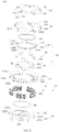
- the shutter structure 100 includes a stator assembly 20, a rotor assembly 40, and a blade assembly 60.
- the stator assembly 20 includes an annular mounting member 24, a base 22 mounted on a first side 2482 of the mounting member 24, and a cover 28 mounted on a second side 2484 of the mounting member 24.
- the base 22 is provided with an aperture 226, the cover 28 is provided with a through-hole 286 corresponding to the aperture 226, and the first side 2482 is opposite to the second side 2484.
- the rotor assembly 40 is sandwiched between the base 22 and the cover 28, the rotor assembly 40 is sleeved over by the mounting member 24 from the second side 2484 and provided with a light-passing hole 42 corresponding to the aperture 226 and the through-hole 286, and the rotor assembly 40 interacts with the stator assembly 20 so that the rotor assembly 40 can rotate relative to the stator assembly 20.
- the blade assembly 60 includes a plurality of blades 62, the plurality of blades 62 is all rotatably connected by a rotating shaft 622 to a side of the cover 28 away from the rotor assembly 40, a guide rod 624 on each blade 62 passes through the cover 28 and the rotor assembly 40 in sequence, and when the rotor assembly 40 rotates relative to the stator assembly 20, the rotor assembly 40 drives the guide rod 624 to move in the cover 28, thereby driving the plurality of blades 62 to rotate around the rotating shaft 622 to at least partially block the through-hole 286 or at least partially open the through-hole 286.
- the plurality of blades 62 is all rotatably connected by the rotating shaft 622 to the side of the cover 28 of the stator assembly 20 away from the rotor assembly 20, the guide rod 624 on each blade 62 passes through the cover 28 and the rotor assembly 40 in sequence, and the rotor assembly 40 interacts with the stator assembly 20 so that the rotor assembly 40 can rotate relative to the stator assembly 20, thereby driving the guide rod 624 to move in the cover 28, and further driving the plurality of blades 62 to rotate around the rotating shaft 622 to at least partially block the through-hole 286 or at least partially open the through-hole 286. Therefore, the shutter structure 100 can avoid using the multi-link structure and the spring structure to implement rotation of the blades 62 and the exposure, thereby keeping the structure simple and compact.
- the stator assembly 20 includes the base 22, the mounting member 24, at least one first magnetic unit 26, and the cover 28.
- the base 22 includes a cylinder-shaped base body 222 and a plurality of connecting arms 224 that extends from an outer peripheral wall of the base body 222.
- the base body 222 has a hollow structure forming the aperture 226.
- the base body 222 includes a first end 2222 proximal to the connecting arm 224 and a second end 2224 opposite to the first end 2222.
- the aperture 226 passes through the first end 2222 and the second end 2224.
- Light reflected by an object in an external scene passes through the aperture 226 and then enters an image sensor (not shown in the figure) of a photographing device 1000 (shown in FIG. 8 ).
- the image sensor is configured to convert an optical signal into an electrical signal to obtain an image.
- the plurality of connecting arms 224 is evenly distributed at intervals in a circumferential direction of the base body 222.
- the plurality of connecting arms 224 is evenly distributed around a center of the aperture 226.
- the quantity of connecting arms 224 is 5, and an included angle between extension lines of length directions of two adjacent connecting arms 224 is 72°.
- the plurality of connecting arms 224 may not be evenly distributed at intervals in the circumferential direction of the base body 222.
- each connecting arm 224 includes an extension portion 2242 that extends from the outer peripheral wall of the base body 222 and a snap-fit portion 2244 that extends from an end of the extension portion 2242 away from the outer peripheral wall.
- the snap-fit portion 2244 vertically extends from the extension portion 2242, and an extension direction faces toward the second end 2224.
- the mounting member 24 sleeves over the base 22 and sits on the plurality of connecting arms 224, and each connecting arm 224 is detachably coupled with the mounting member 24.
- the mounting member 24 includes a mounting ring 242, a supporting portion 244 that extends from an inner wall of the mounting ring 242, and a blocking portion 246 that extends from an end of the supporting portion 244 away from the inner wall.
- the mounting ring 242 is basically in an annular shape.
- the mounting ring 242 includes a first side 2482 (that is, the first side 2482 of the mounting member 24) facing toward the connecting arm 224 and a second side 2844 (that is, the second side 2844 of the mounting member 24) opposite to the first side 2482.
- a plurality of snap-fit slots 2422 corresponding to the plurality of connecting arms 224 is provided on the inner wall of the mounting ring 242, and the snap-fit slots 2422 pass through the first side 2482 and the second side 2844.
- the mounting member 24 sleeves over the base body 222 and sits on the plurality of connecting arms 224, and the snap-fit portion 2244 of each connecting arm 224 is snapped into the snap-fit slot 2422 from the first side 2482, so that each connecting arm 224 is detachably engaged with the inner wall of the mounting ring 242.
- the quantity of snap-fit slots 2422 is 5, and corresponds to the quantity of connecting arms 224.
- the quantity of snap-fit slots 2422 is greater than the quantity of connecting arms 224.
- the mounting ring 242 may be detachably mounted on the connecting arms 224 in other ways, for example, screw connection, thread connection, and the like.
- the supporting portion 244 is fixed on the inner wall of the mounting ring 242, and the other end of the supporting portion 244 faces toward a center of the mounting ring 242.
- the quantity of supporting portions 244 may be 1, 2, 3, 5, 6, 9, 12, 15, 27, or more, and may be set based on a requirement.
- the quantity of supporting portions 244 is 15. Every three of the quantity of supporting portions are evenly disposed at intervals and form a group, and there are five groups in total. The five groups of supporting portions 244 are evenly distributed at intervals around the center of the mounting ring 242.
- a snap-fit slot 2422 is disposed between two adjacent groups of supporting portions 2445.
- each group of supporting portions 244 may include 2, 4, 5, or more supporting portions.
- the plurality of supporting portions 244 may also be randomly distributed around the inner wall of the mounting ring 242.
- the blocking portion 246 is approximately in a plate shape, and a lateral surface of the blocking portion 246 away from the supporting portion 244 is a curved surface, for example, an arc surface. In other embodiments, the lateral surface of the blocking portion 246 away from the supporting portion 244 may also be a flat surface.
- the mounting ring 242, the supporting portion 244, and the blocking portion 246 are an integrated structure, that is, the mounting member 24 is an integrated structure.
- the mounting member 24 may be made of a magnetic material such as soft iron or silicon steel.
- the supporting portion 244 and the blocking portion 246 are an integrated structure, and after being formed, the integrated structure is mounted to the mounting ring 242 by gluing or welding or the like.
- the supporting portion 244 and the blocking portion 246 may be made of a magnetic material such as soft iron or silicon steel, and the mounting ring 242 may be made of another material, for example, plastic or rubber.
- the supporting portion 244 may be detachably connected to the mounting ring 242.
- first magnetic units 26 there may be one or more first magnetic units 26.
- first magnetic units 26 When there is a plurality of first magnetic units 26, for example, 2, 3, 5, 6, 9, or more first magnetic units 26, the plurality of first magnetic units 26 is evenly distributed at intervals in a circumferential direction of an inner ring surface of the mounting ring 242. To be specific, the plurality of first magnetic units 26 is evenly distributed around a central axis of the aperture 226.
- Each first magnetic unit 26 includes N (N is greater than or equal to 2) first magnetic members 262 arranged at intervals. For example, there may be 2, 3, 6, 7, 8, 9, 12, 15, 18, or more first magnetic members 262.
- Each first magnetic member 262 is correspondingly mounted on a supporting portion 244, and is located between the blocking portion 246 and the inner wall of the mounting ring 242.
- the quantity and positions of supporting portions 244 may be set based on the quantity and positions of first magnetic members 262.
- Each first magnetic unit 26 includes three adjacent first magnetic members 262 disposed at intervals.
- the first magnetic member 262 may be a coil, and the coil winds around the supporting portion 244.
- the coil 2622 is configured to generate an electromagnetic field during energization.
- the quantity of turns of the coil 2622 may be 1, 5, 8, 10, 15, 20, 30, 50, or more, and may be set based on an actual requirement. If the quantity of turns of the coil is larger, an electromagnetic force generated by the first magnetic member 262 is greater. If the quantity of first magnetic members 262 is larger, a total electromagnetic force of the first magnetic unit 26 is greater.
- the cover 28 includes a cover body 282 and a plurality of coupling portions 284 that extends from the cover body 282 toward a surface of the base 22, and the cover 28 is mounted on the mounting ring 242.
- the cover body 282 is provided with a through-hole 286 corresponding to and connected to the aperture 226, a plurality of connecting holes 2824 spaced apart from each other, and a plurality of second guide holes 2822.
- the aperture 226 is approximately in a central position.
- the plurality of connecting holes 2824 is evenly disposed at intervals around a center of the cover body 282 (that is, the center of the aperture 226).
- the second guide holes 2822 are located between the aperture 226 and the connecting holes 2824, and are also evenly disposed at intervals around the center of the cover body 282 (that is, the center of the aperture 226), and each connecting hole 2824 corresponds to a second guide hole 2822.
- the second guide hole 2822 is in an arc shape, and a center of curvature of the arc coincides (is the same as) a center of a corresponding connecting hole 2824, and the center of the corresponding connecting hole 2824 and the center of the through-hole 286 are located on a same straight line.
- the quantity of connecting holes 2824 and the quantity of second guide holes 2822 are the same. Both the quantity of connecting holes 2824 and the quantity of second guide holes 2822 may be 2, 4, 5, 6, or 8. In this embodiment, the quantity of connecting holes 2824 is 5.
- the coupling portions 284 are evenly distributed at intervals at an edge of the cover body 282 around the center of the cover body 282 and correspond to the snap-fit slots 2422.
- Each coupling portion 284 is engaged with the inner wall of the mounting ring 242 so that the cover 28 is detachably mounted on the mounting ring 242.
- the plurality of coupling portions 284 is snapped into the snap-fit slots 2422 from the second side 2484, and are opposite to the snap-fit portions 2244.
- each coupling portion 284 corresponds to one snap-fit portion 2244.
- the coupling portion 284 and the corresponding snap-fit portion 2244 are snapped into a same snap-fit slot 2422 simultaneously.
- the quantity of coupling portions 284 may also be 5, and the five coupling portions 284 correspond to five snap-fit slots 2422. In some embodiments. Alternatively, there may be 2, 4, 6, 9, or more coupling portions 284, which may be set based on a requirement. In other embodiments, the mounting ring 242 is additionally provided with a snap-fit slot for snapping the coupling portion 284 onto the inner wall of the mounting ring 242.
- the coupling portion 284 is snapped into the snap-fit slot from the second side 2484, and the snap-fit portion 2244 is snapped into the snap-fit slot 2422 from the first side 2482.
- the method for detachably mounting the cover body 282 on the mounting ring 242 may also be another method, for example, screw connection or thread connection; or the cover body 282 may be mounted on the base 22.
- the base 22, the mounting member 24, and the cover 28 are detachably connected for ease of winding a coil on the mounting member 24.
- the rotor assembly 40 further includes a holder 44, a yoke frame 46, and at least one second magnetic unit 48.
- the rotor assembly 40 sleeves over the base body 222.
- the holder 44 includes a holder body 442 and a plurality of lugs 444 that extends along an outer sidewall of the holder body 442.
- the holder body 442 is in an annular shape, and sleeves over an outer peripheral of the second end 2224 of the base body 222.
- the holder body 442 includes a first surface 4422 facing toward the connecting arm 224 and a second surface 4424 opposite to the first surface 4422.
- a side of the first surface 4422 of the holder body 442 facing toward a center is recessed to form a mounting slot 4426, and the first surface 4422 is further provided with a plurality of gaps 4428 connected to the mounting slot 4426, where the plurality of gaps 4428 is evenly disposed around the center of the holder body 442. There may be 2, 6, 8, 10, 15, 20 or more gaps 4428, which may be set based on a requirement.
- each group of gaps 4428 may include 3, 4, 5 or more gaps. In other embodiments. Alternatively, the gaps 4428 may not be evenly disposed around the center of the holder body 442.
- the holder body 442 extends along an outer sidewall near the second surface 4424 to form a plurality of lugs 444, where the plurality of lugs 444 is evenly disposed at intervals around the center of the holder body 442, and each lug 444 is provided with a first guide hole 4442.
- the first guide hole 4442 is strip-shaped, and extends in an extension direction of the lug 444.
- the quantity of lugs 444 is 5 and corresponds to the quantity of second guide holes 2822, and the five lugs 444 correspond to the five second guide holes 2822 on a one-to-one basis.
- the first guide hole 4442 may be in an arc shape.
- the plurality of lugs 444 may not be evenly disposed at intervals around the center of the holder body 442.
- the yoke frame 46 includes a yoke body 462 and a plurality of mounting portions 464 formed by extension from a surface of the yoke body 462 facing toward the connecting arm 224.
- the yoke body 462 is in an annular shape.
- the plurality of mounting portions 464 is spaced apart from each other, and are evenly distributed around a center of the light-passing hole 42. To be specific, two adjacent mounting portions 464 form a gap. In this embodiment, there are five mounting portions 464, where the five mounting portions 464 are spaced apart from each other, and are evenly distributed around the center of the light-passing hole 42.
- a side of the yoke frame 46 away from the mounting portion 464 is fixedly mounted in the mounting slot 4426 of the holder 44.
- the yoke frame 46 When the yoke frame 46 is fixedly mounted in the mounting slot 4426, the yoke frame 46 may be fixed tightly, or may be connected and fixed by a screw or connected and fixed by a thread, or the like.
- An inner ring of the yoke frame 46 and an inner ring of the holder 44 form a part of the light-passing hole 42, and the light-passing hole 42 corresponds to the aperture 226.
- the inner ring of the yoke frame 46 sleeves over the outer peripheral of the base body 222, and is located between the first end 2222 and the second end 2224 of the base body 222, and may rotate around the base body 222.
- the yoke frame 46 may also be in a complete ring shape without a gap.
- the yoke frame 46 and the holder 44 are integrated.
- the rotor assembly 40 may include only the holder 44, the holder 44 matches the base body 222, and the holder 44 directly sleeves over an outer peripheral of the holder 44.
- the at least one second magnetic unit 48 and the at least one first magnetic unit 26 are disposed in pairs, each first magnetic unit 26 and a corresponding second magnetic unit 48 are oppositely disposed and form a magnetic unit group 50, the first magnetic unit 26 and the second magnetic unit 48 in each magnetic unit group 50 mutually interact to generate a force, and the force causes the second magnetic unit 48 to rotate relative to the first magnetic unit 26.
- a plurality of magnetic unit groups 50 is included, and the plurality of magnetic unit groups 50 is evenly distributed around a central axis of the light-passing hole 42.
- Each second magnetic unit 48 includes N-1 (N is greater than or equal to 2) adjacent second magnetic members 482 arranged at intervals. For example, there may be 1, 2, 5, 6, 7, 8, 11, 14, 17, or more second magnetic members 482.
- Each second magnetic unit 48 further corresponds to a mounting portion 464 and a gap 4428, and each second magnetic unit 48 is mounted on the corresponding mounting portion 464 and exposed from the corresponding gap 4428. In this case, the width of each mounting portion 464 in a circumferential direction of the yoke body 462 is greater than or equal to the width of the corresponding second magnetic unit 48 in a circumferential direction of the holder body 442.
- each second magnetic unit 48 includes two adjacent second magnetic members 482 disposed at intervals.
- the second magnetic member 482 may be a magnet.
- the magnet fits onto an outer sidewall of the mounting portion 464, and magnetic poles of adjacent ends of adjacent magnets are the same.
- the adjacent ends of the adjacent magnets are both S poles, or the adjacent ends of the adjacent magnets are both N poles.
- An electromagnetic field generated by the first magnetic unit 26 during energization generates a force to attract or repel the magnet (that is, the second magnetic member 482) generates a force.
- the interaction between the first magnetic unit 26 and the second magnetic member 482 causes the rotor assembly 40 to rotate around the base body 222.
- the quantity of first magnetic members 262 is greater than the quantity of second magnetic members 482.
- the first force causes the second magnetic unit 482 to rotate in a first direction relative to the first magnetic unit 26, or when two second magnetic members 482 and two first magnetic members 262 located at the other end generate a second force, the second force causes the second magnetic unit 48 to rotate in a second direction relative to the first magnetic unit 26, where the first direction is opposite to the second direction.
- the first magnetic member 262 is a magnet
- the second magnetic member 482 is a coil.
- a relationship between forces of the first magnetic member 262 and the second magnetic member 482 is similar to the foregoing relationship, and is not described again herein.
- the blade assembly 60 includes a plurality of blades 62, a rotating shaft 622 disposed on each blade 62, and a guide rod 624.
- the plurality of blades 62 is evenly distributed around the through-hole 286.
- the plurality of blades 62 is successively connected head-to-tail, and a head of each blade 62 overlaps a tail of another blade 62 at a joint along an axial direction of the aperture 226.
- each blade 62 corresponds to a second guide hole 2822, a connecting hole 2824, a first guide hole 4442, a guide rod 624, and a lug 444.
- An end of each blade 62 is fixed to the rotating shaft 622.
- the rotating shaft 622 passes through the connecting hole 2824 to connect to the cover 28, and the blade 62 may rotate around an axis of the rotating shaft 622.
- the guide rod 624 on each blade 62 passes through the cover body 282 and the rotor assembly 40 in sequence by means of the second guide hole 2822 and the first guide hole 4442.
- Each blade 62 has a recess 626. Recesses 626 of the plurality of blades all face toward the aperture 226.
- the aperture 226 or the through-hole 286 is opened, and the recesses 626 of all the blades 62 may together form an approximately circular hole, where a diameter of the circular hole is greater than or equal to a diameter of the through-hole 286.
- the aperture 226 may be closed or a size of the aperture 226 or the through-hole 286 may be controlled to control the amount of incoming light.
- the blade assembly 60 further includes a mounting plate 64, where an end of the mounting plate 64 is provided with a through-hole corresponding to the connecting hole 2824, and an end of the rotating shaft 622 passes through the through-hole to connect to an end of the blade 62.
- An end of the guide rod 624 is mounted on a lateral surface of the mounting plate 64 facing toward the cover body 282.
- the blade 62 is mounted on a lateral surface of the mounting plate facing away from the cover body 282, and the rotating shaft 622 is fixedly connected to the blade 62 through the through-hole.
- relative positions of the mounting plate 64 and the blade 62 may be adjusted to adjust a pivoting and blocking position of the blade 62 relative to the aperture 226.
- the following describes a specific process in which the blades 62 rotate to at least partially block or at least partially open the through-hole 286.
- a first magnetic member 262 in a first position is a right first magnetic member 262
- a first magnetic member 262 in a second position is a middle first magnetic member 262
- a first magnetic member 262 in a third position is a left first magnetic member 262.
- a second magnetic member 482 in a first position is a right first magnetic member 482
- a second magnetic member 482 in a second position is a left first magnetic member 482.
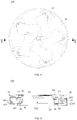
- the guide rod 624 In an initial state, the guide rod 624 is in a first extreme position of the second guide hole 2822 (the position shown in FIG. 7 ), and the five blades 62 completely block the aperture 226 or the through-hole 286.
- the left first magnetic member 262 and the middle first magnetic member 262 are energized, the two first magnetic members 262 (that is, the left first magnetic member 262 and the middle first magnetic member 262) and the two second magnetic members 482 (that is, the left second magnetic member 482 and the right second magnetic member 482) jointly generate a first force.
- the left first magnetic member 262 may magnetically attract the left second magnetic member 482
- the middle first magnetic member 262 may magnetically attract the middle second magnetic member 482, that is, the first force causes the second magnetic members 482 to rotate counterclockwise.
- the second magnetic members 482 are fixedly mounted on the yoke frame 46, and the yoke frame 46 is fixedly mounted on the holder 44
- the second magnetic members 482 rotate counterclockwise to drive the holder 44 to rotate counterclockwise, that is, the lugs 444 of the holder 44 also rotate counterclockwise, so that the guide rod 624 passing through the first guide hole 4442 can move from the first extreme position of the second guide hole 2822 to a second extreme position; and when the guide rod 624 is in the second extreme position, the five blades 62 completely open up the aperture 226 or the through-hole 286, and recesses 626 of the five blades 62 jointly form an approximately circular hole (to reduce a windmill effect and avoid formation of flares, which may otherwise affect imaging).
- the guide rod 624 moves from the first extreme position to the second extreme position, the guide rod 624 is pushed by the lugs 444 and drives all the blades 62 to rotate around the axis of the rotating shaft 622 to gradually open the aperture 226 or the through-hole 286.
- the guide rod 624 moves to a position between the first extreme position and the second extreme position, the aperture 226 or the through-hole 286 is partially opened, or partially blocked.
- a relative position of the guide rod 624 in the second guide hole 2822 may be controlled so that an amount of light passing through the aperture 226 or the through-hole 286 is controlled by the blades 62.
- the guide rod 624 is in the second extreme position of the second guide hole 2822 (a position opposite to the position shown in FIG. 7 ), and the five blades 62 completely open up the aperture 226 or the through-hole 286.
- the two first magnetic members 262 that is, the right first magnetic member 262 and the middle first magnetic member 262
- the two second magnetic members 482 that is, the left second magnetic member 482 and the right second magnetic member 482 jointly generate a second force.
- the right first magnetic member 262 may magnetically attract the right second magnetic member 482
- the middle first magnetic member 262 may magnetically attract the left second magnetic member 482, that is, the second force causes the second magnetic members 482 to rotate clockwise.
- the second magnetic members 482 are fixedly mounted on the yoke frame 46, and the yoke frame 46 is fixedly mounted on the holder 44
- the second magnetic members 482 rotate clockwise to drive the holder 44 to rotate clockwise, that is, the lugs 444 of the holder 44 also rotate clockwise, so that the guide rod 624 passing through the first guide hole 4442 can move from the second extreme position of the second guide hole 2822 to the first extreme position; and when the guide rod 624 is in the first extreme position, the five blades 62 completely block the aperture 226 or the through-hole 286, and the recesses 626 of the five blades 62 jointly form an approximately circular hole (to reduce a windmill effect).
- the guide rod 624 moves from the second extreme position to the first extreme position, the guide rod 624 is pushed by the lugs 444 and drives all the blades 62 to rotate around the axis of the rotating shaft 622 to gradually block the aperture 226 or the through-hole 286.
- the guide rod 624 moves to a position between the first extreme position and the second extreme position, the aperture 226 or the through-hole 286 is partially blocked, or partially opened.
- a relative position of the guide rod 624 in the second guide hole 2822 may be controlled so that an amount of light passing through the aperture 226 or the through-hole 286 is controlled by the blades 62.
- the N-1 second magnetic members 482 may correspond to intervals of the N first magnetic members 262 in sequence.
- Directions of the first force and the second force are opposite, and magnitudes of the first force and the second force may be the same or different, which may be implemented by adjusting the intensity of a current.
- the directions of the first force and the second force may be determined jointly by positive and negative electrodes of the current and magnetic poles of the second magnetic member 482, which may be implemented by adjusting a direction of the current passing through a coil.
- the two first magnetic members 262 that is, the left first magnetic member 262 and the middle first magnetic member 262
- the two second magnetic members 482 that is, the left second magnetic member 482 and the right second magnetic member 482
- the two first magnetic members 262 that is, the left first magnetic member 262 and the middle first magnetic member 262
- the two second magnetic members 482 that is, the left second magnetic member 482 and the right second magnetic member 482
- the quantity of magnetic unit groups 50 may remain unchanged, and the magnitudes of the first force and the second force may be increased by increasing the quantity of first magnetic members 262 and second magnetic members 482 in each magnetic unit group 50. Alternatively, the magnitudes of the first force and the second force may be increased by increasing the quantity of magnetic unit groups 50. Alternatively, both the quantity of magnetic unit groups 50 and the quantity of first magnetic members 262 and second magnetic members 482 in each magnetic unit group 50 are increased to increase the magnitudes of the first force and the second force.
- the shutter structure 100 may further include a first washer 82, where the first washer 82 sleeves over the first end 2222 of the base body 222 and located between the rotor assembly 40 and the connecting arm 224.
- the shutter structure 100 may further include a second washer 84, where the second washer 84 sleeves over the second end 2224 of the base body 222 and accommodated in the holder body 442.
- a second washer 84 sleeves over the second end 2224 of the base body 222 and accommodated in the holder body 442.
- an end surface of the second end 2224 of the base body 222 and the outer sidewall jointly form a groove for mounting the second washer 84, an inner ring of the second washer 84 sleeves over a groove wall of the groove, and an outer ring of the second washer 84 abuts against an inner surface of the holder 44.
- a surface of the second washer 84 facing toward the connecting arm 224 at least partially abuts against a bottom of the groove, and another part of the surface of the second washer 84 facing toward the connecting arm 224 abuts against an end surface of the yoke frame 46 away from the mounting portion 464.
- the first washer 82 and the second washer 84 may be both disposed, or only one of them may be disposed.
- the first washer 82 and the second washer 84 are configured to reduce friction between the rotor assembly 40 and the stator assembly 20.
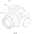
- the present application further provides a photographing device 1000, where the photographing device 1000 includes a housing 200 and the shutter structure in any one of the foregoing embodiments.
- the shutter structure 100 is assembled with the housing 200.
- the photographing device 1000 may be a component or a terminal device having a photographing function, such as a lens module, a camera module, a camera, a camera, a mobile phone, and so on.
- the plurality of blades 62 is all rotatably connected by the rotating shaft 622 to the side of the cover 28 of the stator assembly 20 away from the rotor assembly 20, the guide rod 624 on each blade 62 passes through the cover 28 and the rotor assembly 40 in sequence, and the rotor assembly 40 interacts with the stator assembly 20 so that the rotor assembly 40 can rotate relative to the stator assembly 20, thereby driving the guide rod 624 to move in the cover 28, and further driving the plurality of blades 62 to rotate around the rotating shaft 622 to at least partially block the through-hole 286 or at least partially open the through-hole 286. Therefore, the shutter structure 100 can avoid using the multi-link structure and the spring structure to implement rotation of the blades 62 and the exposure, thereby keeping the structure simple and compact.
- a first feature is “above” or “below” a second feature may include that the first feature and the second feature are in direct contact, or may include that the first feature and the second feature are not in direct contact but come into contact through an additional feature between the first feature and the second feature.
- the first feature is "above”, “over”, or “on the top of” the second feature includes that the first feature is directly above and obliquely above the second feature or only indicates that a level of the first feature is higher than that of the second feature.
- That the first feature is “below”, “under”, or “at the bottom of' the second feature includes that the first feature is directly under and obliquely under the second feature or only indicates that the level of the first feature is lower than that of the second feature.
Landscapes
- Physics & Mathematics (AREA)
- General Physics & Mathematics (AREA)
- Studio Devices (AREA)
- Shutters For Cameras (AREA)
Abstract
Description
- The present application relates to the field of imaging technologies, and more specifically, to a shutter structure and a photographing device.
- With the rapid development of science and technology, higher requirements are imposed on imaging technologies of electronic devices having photographing functions, such as mobile phones, camcorders, and cameras. Most of the existing inter-lens shutters use a plurality of connecting rods and spring structures to implement lens opening and closing and exposure. However, a inter-lens shutter of this structure is complex and not compact.
- Embodiments of the present application provide a shutter structure and a photographing device.
- The present application provides a shutter structure. The shutter structure includes a stator assembly, a rotor assembly, and a blade assembly. The stator assembly includes an annular mounting member, a base mounted on a first side of the mounting member, and a cover mounted on a second side of the mounting member, the base is provided with an aperture, the cover is provided with a through-hole corresponding to the aperture, and the first side is opposite to the second side. The rotor assembly is sandwiched between the base and the cover, the rotor assembly is sleeved over by the mounting member from the second side and provided with a light-passing hole corresponding to the aperture and the through-hole, and the rotor assembly interacts with the stator assembly so that the rotor assembly is rotatable relative to the stator assembly. The blade assembly includes a plurality of blades, the plurality of blades is all rotatably connected by a rotating shaft to a side of the cover away from the rotor assembly, a guide rod on each blade passes through the cover and the rotor assembly in sequence, and when the rotor assembly rotates relative to the stator assembly, the rotor assembly drives the guide rod to move in the cover, thereby driving the plurality of blades to rotate around an axis of the rotating shaft to at least partially block the through-hole or at least partially open the through-hole.
- The present application provides a photographing device. The photographing device includes a housing and a shutter structure. The shutter structure is assembled with the housing. The shutter structure includes a stator assembly, a rotor assembly, and a blade assembly. The stator assembly includes an annular mounting member, a base mounted on a first side of the mounting member, and a cover mounted on a second side of the mounting member, the base is provided with an aperture, the cover is provided with a through-hole corresponding to the aperture, and the first side is opposite to the second side. The rotor assembly is sandwiched between the base and the cover, the rotor assembly is sleeved over by the mounting member from the second side and provided with a light-passing hole corresponding to the aperture and the through-hole, and the rotor assembly interacts with the stator assembly so that the rotor assembly is rotatable relative to the stator assembly. The blade assembly, wherein the blade assembly includes a plurality of blades, the plurality of blades is all rotatably connected by a rotating shaft to a side of the cover away from the rotor assembly, a guide rod on each blade passes through the cover and the rotor assembly in sequence, and when the rotor assembly rotates relative to the stator assembly, the rotor assembly drives the guide rod to move in the cover, thereby driving the plurality of blades to rotate around an axis of the rotating shaft to at least partially block the through-hole or at least partially open the through-hole.
- In the photographing device according to this embodiment of the present application, the plurality of blades is all rotatably connected by the rotating shaft to the side of the cover of the stator assembly away from the rotor assembly, the guide rod on each blade passes through the cover and the rotor assembly in sequence, and the rotor assembly interacts with the stator assembly so that the rotor assembly is rotatable relative to the stator assembly, thereby driving the guide rod to move in the cover, and further driving the plurality of blades to rotate around the rotating shaft to at least partially block the through-hole or at least partially open the through-hole. Therefore, the shutter structure can avoid using the multi-link structure and the spring structure to implement rotation of the blades and the exposure, thereby keeping the structure simple and compact.
- The additional aspects and advantages of the embodiments of the present application will be partly given in the following description, and part of them will become clear from the following description, or be understood through the practice of the embodiments of the present application.
- The foregoing and/or additional aspects and advantages of the present application become more apparent and comprehensible in the descriptions of embodiments in combination with the accompanying drawings.
-
FIG. 1 is a schematic assembled three-dimensional view of a shutter structure from one perspective according to an embodiment of the present application; -
FIG. 2 is a schematic assembled three-dimensional view of the shutter structure shown inFIG. 1 from another perspective; -
FIG. 3 is a schematic exploded three-dimensional view of the shutter structure shown inFIG. 1 from one perspective; -
FIG. 4 is a schematic plan view of the shutter structure shown inFIG. 1 from one perspective; -
FIG. 5 is a schematic cross-sectional view of the shutter structure shown inFIG. 4 along a cross-section line V-V; -
FIG. 6 is a top view of the shutter structure shown inFIG. 2 ; -
FIG. 7 is a schematic cross-sectional view ofFIG. 6 along a cross-section line VII-VII; and -
FIG. 8 is a schematic view of a three-dimensional structure of a photographing device according to an embodiment of the present application. - Reference numerals of main components:
shutter structure 100,stator assembly 20,base 22,base body 222,first end 2222,second end 2224, connectingarm 224,extension portion 2242, snap-fit portion 2244,aperture 226,mounting member 24,mounting ring 242, snap-fit slot 2422; supportingportion 244,blocking portion 246, firstmagnetic unit 26, firstmagnetic member 262,cover 28,cover body 282,second guide hole 2822, connectinghole 2824,coupling portion 284, through-hole 286,rotor assembly 40, light-passing hole 42,holder 44,holder body 442,first surface 4422,second surface 4424,mounting slot 4426,gap 4428,lug 444,first guide hole 4442,yoke frame 46,yoke body 462,mounting portion 464, secondmagnetic unit 48, secondmagnetic member 482,magnetic unit group 50,blade assembly 60,blade 62,rotating shaft 622,guide rod 624,recess 626,first washer 82,second washer 84, photographingdevice 1000, andhousing 200. - The following describes the embodiments of the present application in detail. Examples of the embodiments are illustrated in the accompanying drawings, where eidentical or similar reference numerals always represent identical or similar components or components having identical or similar functions. The following embodiments described with reference to the accompanying drawings are exemplary and are used only to explain the present application and should not be understood as limitations on the present application.
- In the descriptions of the present application, it should be understood that directions or position relationships indicated by terms "center", " longitudinal", " lateral", "length", "width", "thickness", "up", "down", "front", "rear", "left", "right", "vertical", "horizontal", "top", "bottom", "internal", "external", "clockwise", and "counterclockwise" are directions or position relationships based on the accompanying drawings, and are used only for conveniently describing the present application and simplifying the descriptions, but do not indicate or imply that a corresponding apparatus or component must have a specific direction and must be constructed and operated in a specific direction, and therefore cannot be understood as limitations on the present application. In addition, the terms "first" and "second" are intended only for description, and shall not be understood as an indication or implication of relative importance or an implicit indication of the quantity of indicated technical features. Therefore, a feature defined by "first" or "second" may explicitly or implicitly include one or more features. In the descriptions of the present application, "plurality" means two or more unless otherwise defined.
- In the descriptions of the present application, it should be noted that unless otherwise specified and defined, terms "mounted", "connected", and "connection" should be understood in a broad sense. For example, the connection may be a fixed connection, or may be a detachable connection or an integrated connection. The connection may be mechanical, or may be electrical. The connection may be a direct connection, or may be an indirect connection through an intermediate medium, or may be an internal connection between two components or an interaction relationship between two components. A person of ordinary skill in the art may understand specific meanings of these terms in the present application based on specific situations.
- Referring to
FIG. 1 to FIG. 3 , the present application provides ashutter structure 100. Theshutter structure 100 includes astator assembly 20, arotor assembly 40, and ablade assembly 60. Thestator assembly 20 includes anannular mounting member 24, abase 22 mounted on afirst side 2482 of themounting member 24, and acover 28 mounted on asecond side 2484 of themounting member 24. Thebase 22 is provided with anaperture 226, thecover 28 is provided with a through-hole 286 corresponding to theaperture 226, and thefirst side 2482 is opposite to thesecond side 2484. Therotor assembly 40 is sandwiched between thebase 22 and thecover 28, therotor assembly 40 is sleeved over by themounting member 24 from thesecond side 2484 and provided with a light-passing hole 42 corresponding to theaperture 226 and the through-hole 286, and therotor assembly 40 interacts with thestator assembly 20 so that therotor assembly 40 can rotate relative to thestator assembly 20. Theblade assembly 60 includes a plurality ofblades 62, the plurality ofblades 62 is all rotatably connected by arotating shaft 622 to a side of thecover 28 away from therotor assembly 40, aguide rod 624 on eachblade 62 passes through thecover 28 and therotor assembly 40 in sequence, and when therotor assembly 40 rotates relative to thestator assembly 20, therotor assembly 40 drives theguide rod 624 to move in thecover 28, thereby driving the plurality ofblades 62 to rotate around therotating shaft 622 to at least partially block the through-hole 286 or at least partially open the through-hole 286. - In the
shutter structure 100 in this embodiment of the present application, the plurality ofblades 62 is all rotatably connected by therotating shaft 622 to the side of thecover 28 of thestator assembly 20 away from therotor assembly 20, theguide rod 624 on eachblade 62 passes through thecover 28 and therotor assembly 40 in sequence, and therotor assembly 40 interacts with thestator assembly 20 so that therotor assembly 40 can rotate relative to thestator assembly 20, thereby driving theguide rod 624 to move in thecover 28, and further driving the plurality ofblades 62 to rotate around the rotatingshaft 622 to at least partially block the through-hole 286 or at least partially open the through-hole 286. Therefore, theshutter structure 100 can avoid using the multi-link structure and the spring structure to implement rotation of theblades 62 and the exposure, thereby keeping the structure simple and compact. - Specifically, referring to
FIG. 3 , thestator assembly 20 includes thebase 22, themounting member 24, at least one firstmagnetic unit 26, and thecover 28. - The
base 22 includes a cylinder-shaped base body 222 and a plurality of connectingarms 224 that extends from an outer peripheral wall of thebase body 222. - The
base body 222 has a hollow structure forming theaperture 226. Thebase body 222 includes afirst end 2222 proximal to the connectingarm 224 and asecond end 2224 opposite to thefirst end 2222. Theaperture 226 passes through thefirst end 2222 and thesecond end 2224. Light reflected by an object in an external scene passes through theaperture 226 and then enters an image sensor (not shown in the figure) of a photographing device 1000 (shown inFIG. 8 ). The image sensor is configured to convert an optical signal into an electrical signal to obtain an image. - There is a plurality of connecting
arms 224, which are located at thefirst end 2222 of thebase body 222. The plurality of connectingarms 224 is evenly distributed at intervals in a circumferential direction of thebase body 222. To be specific, the plurality of connectingarms 224 is evenly distributed around a center of theaperture 226. There may be 2, 3, 4, 5, 6, 8, or moreconnecting arms 224, which may be set based on an actual requirement. In this embodiment, the quantity of connectingarms 224 is 5, and an included angle between extension lines of length directions of two adjacent connectingarms 224 is 72°. In other embodiments, the plurality of connectingarms 224 may not be evenly distributed at intervals in the circumferential direction of thebase body 222. For example, there are also five connectingarms 224, but included angles between extension lines of length directions of any two connectingarms 224 are mutually different. Gaps between the connectingarms 224 facilitate heat dissipation of a firstmagnetic member 262. In some embodiments, the connectingarm 224 may also be an annular substrate. To be specific, the plurality of connectingarms 224 forms a complete annular structure and surround thefirst end 2222 of the outer peripheral wall of thebase body 222. Specifically, each connectingarm 224 includes anextension portion 2242 that extends from the outer peripheral wall of thebase body 222 and a snap-fit portion 2244 that extends from an end of theextension portion 2242 away from the outer peripheral wall. In this embodiment, the snap-fit portion 2244 vertically extends from theextension portion 2242, and an extension direction faces toward thesecond end 2224. - Still referring to
FIG. 3 , the mountingmember 24 sleeves over thebase 22 and sits on the plurality of connectingarms 224, and each connectingarm 224 is detachably coupled with the mountingmember 24. Specifically, the mountingmember 24 includes a mountingring 242, a supportingportion 244 that extends from an inner wall of the mountingring 242, and a blockingportion 246 that extends from an end of the supportingportion 244 away from the inner wall. - The mounting
ring 242 is basically in an annular shape. The mountingring 242 includes a first side 2482 (that is, thefirst side 2482 of the mounting member 24) facing toward the connectingarm 224 and a second side 2844 (that is, the second side 2844 of the mounting member 24) opposite to thefirst side 2482. A plurality of snap-fit slots 2422 corresponding to the plurality of connectingarms 224 is provided on the inner wall of the mountingring 242, and the snap-fit slots 2422 pass through thefirst side 2482 and the second side 2844. The mountingmember 24 sleeves over thebase body 222 and sits on the plurality of connectingarms 224, and the snap-fit portion 2244 of each connectingarm 224 is snapped into the snap-fit slot 2422 from thefirst side 2482, so that each connectingarm 224 is detachably engaged with the inner wall of the mountingring 242. In this embodiment, the quantity of snap-fit slots 2422 is 5, and corresponds to the quantity of connectingarms 224. In other embodiments, there may be 2, 3, 6, or more snap-fit slots 2422, and the quantity of snap-fit slots 2422 may not be the same as the quantity of connectingarms 224 either. For example, the quantity of snap-fit slots 2422 is greater than the quantity of connectingarms 224. In other embodiments, the mountingring 242 may be detachably mounted on the connectingarms 224 in other ways, for example, screw connection, thread connection, and the like. - One end of the supporting
portion 244 is fixed on the inner wall of the mountingring 242, and the other end of the supportingportion 244 faces toward a center of the mountingring 242. There is a plurality of supportingportions 244, and the plurality of supportingportions 244 is evenly distributed at intervals around the center of the mountingring 242. The quantity of supportingportions 244 may be 1, 2, 3, 5, 6, 9, 12, 15, 27, or more, and may be set based on a requirement. In this embodiment, the quantity of supportingportions 244 is 15. Every three of the quantity of supporting portions are evenly disposed at intervals and form a group, and there are five groups in total. The five groups of supportingportions 244 are evenly distributed at intervals around the center of the mountingring 242. A snap-fit slot 2422 is disposed between two adjacent groups of supporting portions 2445. In other embodiments, each group of supportingportions 244 may include 2, 4, 5, or more supporting portions. In other embodiments, the plurality of supportingportions 244 may also be randomly distributed around the inner wall of the mountingring 242. - An end of the supporting
portion 244 away from the inner wall extends to form the blockingportion 246. The blockingportion 246 is approximately in a plate shape, and a lateral surface of the blockingportion 246 away from the supportingportion 244 is a curved surface, for example, an arc surface. In other embodiments, the lateral surface of the blockingportion 246 away from the supportingportion 244 may also be a flat surface. - In this embodiment, the mounting
ring 242, the supportingportion 244, and the blockingportion 246 are an integrated structure, that is, the mountingmember 24 is an integrated structure. The mountingmember 24 may be made of a magnetic material such as soft iron or silicon steel. In other embodiments, the supportingportion 244 and the blockingportion 246 are an integrated structure, and after being formed, the integrated structure is mounted to the mountingring 242 by gluing or welding or the like. The supportingportion 244 and the blockingportion 246 may be made of a magnetic material such as soft iron or silicon steel, and the mountingring 242 may be made of another material, for example, plastic or rubber. The supportingportion 244 may be detachably connected to the mountingring 242. - With reference to
FIG. 7 , there may be one or more firstmagnetic units 26. When there is a plurality of firstmagnetic units 26, for example, 2, 3, 5, 6, 9, or more firstmagnetic units 26, the plurality of firstmagnetic units 26 is evenly distributed at intervals in a circumferential direction of an inner ring surface of the mountingring 242. To be specific, the plurality of firstmagnetic units 26 is evenly distributed around a central axis of theaperture 226. Each firstmagnetic unit 26 includes N (N is greater than or equal to 2) firstmagnetic members 262 arranged at intervals. For example, there may be 2, 3, 6, 7, 8, 9, 12, 15, 18, or more firstmagnetic members 262. Each firstmagnetic member 262 is correspondingly mounted on a supportingportion 244, and is located between the blockingportion 246 and the inner wall of the mountingring 242. To be specific, the quantity and positions of supportingportions 244 may be set based on the quantity and positions of firstmagnetic members 262. In this embodiment, there are five firstmagnetic units 26, and the five firstmagnetic units 26 are evenly distributed at intervals in a circumferential direction of an inner ring of the mountingring 242. Each firstmagnetic unit 26 includes three adjacent firstmagnetic members 262 disposed at intervals. The firstmagnetic member 262 may be a coil, and the coil winds around the supportingportion 244. The coil 2622 is configured to generate an electromagnetic field during energization. The quantity of turns of the coil 2622 may be 1, 5, 8, 10, 15, 20, 30, 50, or more, and may be set based on an actual requirement. If the quantity of turns of the coil is larger, an electromagnetic force generated by the firstmagnetic member 262 is greater. If the quantity of firstmagnetic members 262 is larger, a total electromagnetic force of the firstmagnetic unit 26 is greater. - Referring to
FIG. 3 to FIG. 5 , thecover 28 includes acover body 282 and a plurality ofcoupling portions 284 that extends from thecover body 282 toward a surface of thebase 22, and thecover 28 is mounted on the mountingring 242. - The
cover body 282 is provided with a through-hole 286 corresponding to and connected to theaperture 226, a plurality of connectingholes 2824 spaced apart from each other, and a plurality of second guide holes 2822. Theaperture 226 is approximately in a central position. The plurality of connectingholes 2824 is evenly disposed at intervals around a center of the cover body 282 (that is, the center of the aperture 226). The second guide holes 2822 are located between theaperture 226 and the connectingholes 2824, and are also evenly disposed at intervals around the center of the cover body 282 (that is, the center of the aperture 226), and each connectinghole 2824 corresponds to asecond guide hole 2822. Thesecond guide hole 2822 is in an arc shape, and a center of curvature of the arc coincides (is the same as) a center of a corresponding connectinghole 2824, and the center of the corresponding connectinghole 2824 and the center of the through-hole 286 are located on a same straight line. The quantity of connectingholes 2824 and the quantity of second guide holes 2822 are the same. Both the quantity of connectingholes 2824 and the quantity of second guide holes 2822 may be 2, 4, 5, 6, or 8. In this embodiment, the quantity of connectingholes 2824 is 5. - The
coupling portions 284 are evenly distributed at intervals at an edge of thecover body 282 around the center of thecover body 282 and correspond to the snap-fit slots 2422. There is a plurality ofcoupling portions 284. Eachcoupling portion 284 is engaged with the inner wall of the mountingring 242 so that thecover 28 is detachably mounted on the mountingring 242. Specifically, the plurality ofcoupling portions 284 is snapped into the snap-fit slots 2422 from thesecond side 2484, and are opposite to the snap-fit portions 2244. In this embodiment, eachcoupling portion 284 corresponds to one snap-fit portion 2244. Thecoupling portion 284 and the corresponding snap-fit portion 2244 are snapped into a same snap-fit slot 2422 simultaneously. This can not only facilitate mounting and dismounting of theshutter structure 100, but also make theshutter structure 100 more compact and lighter structurally. To be specific, in this embodiment, the quantity ofcoupling portions 284 may also be 5, and the fivecoupling portions 284 correspond to five snap-fit slots 2422. In some embodiments. Alternatively, there may be 2, 4, 6, 9, ormore coupling portions 284, which may be set based on a requirement. In other embodiments, the mountingring 242 is additionally provided with a snap-fit slot for snapping thecoupling portion 284 onto the inner wall of the mountingring 242. In this case, thecoupling portion 284 is snapped into the snap-fit slot from thesecond side 2484, and the snap-fit portion 2244 is snapped into the snap-fit slot 2422 from thefirst side 2482. In other embodiments, the method for detachably mounting thecover body 282 on the mountingring 242 may also be another method, for example, screw connection or thread connection; or thecover body 282 may be mounted on thebase 22. In this embodiment, thebase 22, the mountingmember 24, and thecover 28 are detachably connected for ease of winding a coil on the mountingmember 24. - Referring to
FIG. 3 ,FIG. 6, and FIG. 7 , therotor assembly 40 further includes aholder 44, ayoke frame 46, and at least one secondmagnetic unit 48. Therotor assembly 40 sleeves over thebase body 222. - The
holder 44 includes aholder body 442 and a plurality oflugs 444 that extends along an outer sidewall of theholder body 442. - The
holder body 442 is in an annular shape, and sleeves over an outer peripheral of thesecond end 2224 of thebase body 222. Theholder body 442 includes afirst surface 4422 facing toward the connectingarm 224 and asecond surface 4424 opposite to thefirst surface 4422. A side of thefirst surface 4422 of theholder body 442 facing toward a center is recessed to form a mountingslot 4426, and thefirst surface 4422 is further provided with a plurality ofgaps 4428 connected to the mountingslot 4426, where the plurality ofgaps 4428 is evenly disposed around the center of theholder body 442. There may be 2, 6, 8, 10, 15, 20 ormore gaps 4428, which may be set based on a requirement. In this embodiment, there are 10gaps 4428, where every two gaps are adjacent and are spaced apart to form a group, and there are five groups in total. The five groups ofgaps 4428 are evenly disposed at intervals around the center of theholder body 442. In other embodiments, each group ofgaps 4428 may include 3, 4, 5 or more gaps. In other embodiments. Alternatively, thegaps 4428 may not be evenly disposed around the center of theholder body 442. - The
holder body 442 extends along an outer sidewall near thesecond surface 4424 to form a plurality oflugs 444, where the plurality oflugs 444 is evenly disposed at intervals around the center of theholder body 442, and eachlug 444 is provided with afirst guide hole 4442. Thefirst guide hole 4442 is strip-shaped, and extends in an extension direction of thelug 444. When theholder body 442 rotates on thebase body 222, thefirst guide hole 4442 and thesecond guide hole 2822 always have an overlapping part. There may be 2, 3, 5, 6, 8, 10, ormore lugs 444, which may be set based on a requirement. In this embodiment, the quantity oflugs 444 is 5 and corresponds to the quantity of second guide holes 2822, and the fivelugs 444 correspond to the five second guide holes 2822 on a one-to-one basis. In some embodiments, thefirst guide hole 4442 may be in an arc shape. In other embodiments, the plurality oflugs 444 may not be evenly disposed at intervals around the center of theholder body 442. - The
yoke frame 46 includes ayoke body 462 and a plurality of mountingportions 464 formed by extension from a surface of theyoke body 462 facing toward the connectingarm 224. Theyoke body 462 is in an annular shape. The plurality of mountingportions 464 is spaced apart from each other, and are evenly distributed around a center of the light-passinghole 42. To be specific, two adjacent mountingportions 464 form a gap. In this embodiment, there are five mountingportions 464, where the five mountingportions 464 are spaced apart from each other, and are evenly distributed around the center of the light-passinghole 42. A side of theyoke frame 46 away from the mountingportion 464 is fixedly mounted in the mountingslot 4426 of theholder 44. When theyoke frame 46 is fixedly mounted in the mountingslot 4426, theyoke frame 46 may be fixed tightly, or may be connected and fixed by a screw or connected and fixed by a thread, or the like. An inner ring of theyoke frame 46 and an inner ring of theholder 44 form a part of the light-passinghole 42, and the light-passinghole 42 corresponds to theaperture 226. The inner ring of theyoke frame 46 sleeves over the outer peripheral of thebase body 222, and is located between thefirst end 2222 and thesecond end 2224 of thebase body 222, and may rotate around thebase body 222. In other embodiments, theyoke frame 46 may also be in a complete ring shape without a gap. - Still referring to
FIG. 3 , in some embodiments, theyoke frame 46 and theholder 44 are integrated. In other embodiments, therotor assembly 40 may include only theholder 44, theholder 44 matches thebase body 222, and theholder 44 directly sleeves over an outer peripheral of theholder 44. - With reference to
FIG. 3 ,FIG. 5 , andFIG. 7 , the at least one secondmagnetic unit 48 and the at least one firstmagnetic unit 26 are disposed in pairs, each firstmagnetic unit 26 and a corresponding secondmagnetic unit 48 are oppositely disposed and form amagnetic unit group 50, the firstmagnetic unit 26 and the secondmagnetic unit 48 in eachmagnetic unit group 50 mutually interact to generate a force, and the force causes the secondmagnetic unit 48 to rotate relative to the firstmagnetic unit 26. In this embodiment, a plurality ofmagnetic unit groups 50 is included, and the plurality ofmagnetic unit groups 50 is evenly distributed around a central axis of the light-passinghole 42. - There may be one or more second
magnetic units 48. When there is a plurality of secondmagnetic units 48, for example, 2, 3, 5, 6, 9, or more secondmagnetic units 48, the plurality of secondmagnetic units 48 is evenly distributed around the central axis of the light-passinghole 42. Each secondmagnetic unit 48 includes N-1 (N is greater than or equal to 2) adjacent secondmagnetic members 482 arranged at intervals. For example, there may be 1, 2, 5, 6, 7, 8, 11, 14, 17, or more secondmagnetic members 482. Each secondmagnetic unit 48 further corresponds to a mountingportion 464 and agap 4428, and each secondmagnetic unit 48 is mounted on the corresponding mountingportion 464 and exposed from thecorresponding gap 4428. In this case, the width of each mountingportion 464 in a circumferential direction of theyoke body 462 is greater than or equal to the width of the corresponding secondmagnetic unit 48 in a circumferential direction of theholder body 442. - Referring to
FIG. 7 , in this embodiment, there are five secondmagnetic units 48, and the five secondmagnetic units 48 are evenly distributed around the central axis of the light-passinghole 42. Each secondmagnetic unit 48 includes two adjacent secondmagnetic members 482 disposed at intervals. The secondmagnetic member 482 may be a magnet. The magnet fits onto an outer sidewall of the mountingportion 464, and magnetic poles of adjacent ends of adjacent magnets are the same. For example, the adjacent ends of the adjacent magnets are both S poles, or the adjacent ends of the adjacent magnets are both N poles. An electromagnetic field generated by the firstmagnetic unit 26 during energization generates a force to attract or repel the magnet (that is, the second magnetic member 482) generates a force. The interaction between the firstmagnetic unit 26 and the secondmagnetic member 482 causes therotor assembly 40 to rotate around thebase body 222. - In some embodiments, the quantity of first
magnetic members 262 is greater than the quantity of secondmagnetic members 482. In a samemagnetic unit group 50, when two secondmagnetic members 482 and two firstmagnetic members 262 located at one end generate a first force, the first force causes the secondmagnetic unit 482 to rotate in a first direction relative to the firstmagnetic unit 26, or when two secondmagnetic members 482 and two firstmagnetic members 262 located at the other end generate a second force, the second force causes the secondmagnetic unit 48 to rotate in a second direction relative to the firstmagnetic unit 26, where the first direction is opposite to the second direction. - In some embodiments, the first
magnetic member 262 is a magnet, and the secondmagnetic member 482 is a coil. In this case, a relationship between forces of the firstmagnetic member 262 and the secondmagnetic member 482 is similar to the foregoing relationship, and is not described again herein. - Referring to
FIG. 3 ,FIG. 4 , andFIG. 7 , theblade assembly 60 includes a plurality ofblades 62, arotating shaft 622 disposed on eachblade 62, and aguide rod 624. - There is a plurality of
blades 62, and the plurality ofblades 62 is evenly distributed around the through-hole 286. When theblades 62 completely open up theaperture 226, the plurality ofblades 62 is successively connected head-to-tail, and a head of eachblade 62 overlaps a tail of anotherblade 62 at a joint along an axial direction of theaperture 226. There may be 2, 3, 5, 6, 8, ormore blades 62, which may be set based on a requirement, as long as the quantity corresponds to quantities oflugs 444, second guide holes 2822, and connectingholes 2824. In this embodiment, there are fiveblades 62, and eachblade 62 corresponds to asecond guide hole 2822, a connectinghole 2824, afirst guide hole 4442, aguide rod 624, and alug 444. An end of eachblade 62 is fixed to therotating shaft 622. Therotating shaft 622 passes through the connectinghole 2824 to connect to thecover 28, and theblade 62 may rotate around an axis of therotating shaft 622. Theguide rod 624 on eachblade 62 passes through thecover body 282 and therotor assembly 40 in sequence by means of thesecond guide hole 2822 and thefirst guide hole 4442. Eachblade 62 has arecess 626.Recesses 626 of the plurality of blades all face toward theaperture 226. When the plurality ofblades 62 rotates in the first direction (for example, clockwise), theaperture 226 or the through-hole 286 is opened, and therecesses 626 of all theblades 62 may together form an approximately circular hole, where a diameter of the circular hole is greater than or equal to a diameter of the through-hole 286. When the plurality ofblades 62 rotates in the second direction (for example, counterclockwise), theaperture 226 may be closed or a size of theaperture 226 or the through-hole 286 may be controlled to control the amount of incoming light. - In some embodiments, the
blade assembly 60 further includes a mountingplate 64, where an end of the mountingplate 64 is provided with a through-hole corresponding to the connectinghole 2824, and an end of therotating shaft 622 passes through the through-hole to connect to an end of theblade 62. An end of theguide rod 624 is mounted on a lateral surface of the mountingplate 64 facing toward thecover body 282. Theblade 62 is mounted on a lateral surface of the mounting plate facing away from thecover body 282, and therotating shaft 622 is fixedly connected to theblade 62 through the through-hole. In some examples, relative positions of the mountingplate 64 and theblade 62 may be adjusted to adjust a pivoting and blocking position of theblade 62 relative to theaperture 226. - The following describes a specific process in which the
blades 62 rotate to at least partially block or at least partially open the through-hole 286. - Referring to
FIG. 3 andFIG. 7 , in eachmagnetic unit group 50, in a counterclockwise arrangement in each firstmagnetic unit 26, a firstmagnetic member 262 in a first position is a right firstmagnetic member 262, a firstmagnetic member 262 in a second position is a middle firstmagnetic member 262, and a firstmagnetic member 262 in a third position is a left firstmagnetic member 262. In each secondmagnetic unit 48, a secondmagnetic member 482 in a first position is a right firstmagnetic member 482, and a secondmagnetic member 482 in a second position is a left firstmagnetic member 482. - In an initial state, the
guide rod 624 is in a first extreme position of the second guide hole 2822 (the position shown inFIG. 7 ), and the fiveblades 62 completely block theaperture 226 or the through-hole 286. When the left firstmagnetic member 262 and the middle firstmagnetic member 262 are energized, the two first magnetic members 262 (that is, the left firstmagnetic member 262 and the middle first magnetic member 262) and the two second magnetic members 482 (that is, the left secondmagnetic member 482 and the right second magnetic member 482) jointly generate a first force. Specifically, the left firstmagnetic member 262 may magnetically attract the left secondmagnetic member 482, and the middle firstmagnetic member 262 may magnetically attract the middle secondmagnetic member 482, that is, the first force causes the secondmagnetic members 482 to rotate counterclockwise. Because the secondmagnetic members 482 are fixedly mounted on theyoke frame 46, and theyoke frame 46 is fixedly mounted on theholder 44, the secondmagnetic members 482 rotate counterclockwise to drive theholder 44 to rotate counterclockwise, that is, thelugs 444 of theholder 44 also rotate counterclockwise, so that theguide rod 624 passing through thefirst guide hole 4442 can move from the first extreme position of thesecond guide hole 2822 to a second extreme position; and when theguide rod 624 is in the second extreme position, the fiveblades 62 completely open up theaperture 226 or the through-hole 286, and recesses 626 of the fiveblades 62 jointly form an approximately circular hole (to reduce a windmill effect and avoid formation of flares, which may otherwise affect imaging). When theguide rod 624 moves from the first extreme position to the second extreme position, theguide rod 624 is pushed by thelugs 444 and drives all theblades 62 to rotate around the axis of therotating shaft 622 to gradually open theaperture 226 or the through-hole 286. When theguide rod 624 moves to a position between the first extreme position and the second extreme position, theaperture 226 or the through-hole 286 is partially opened, or partially blocked. In other words, a relative position of theguide rod 624 in thesecond guide hole 2822 may be controlled so that an amount of light passing through theaperture 226 or the through-hole 286 is controlled by theblades 62. - In another initial state, the
guide rod 624 is in the second extreme position of the second guide hole 2822 (a position opposite to the position shown inFIG. 7 ), and the fiveblades 62 completely open up theaperture 226 or the through-hole 286. When the right firstmagnetic member 262 and the middle firstmagnetic member 262 are energized, the two first magnetic members 262 (that is, the right firstmagnetic member 262 and the middle first magnetic member 262) and the two second magnetic members 482 (that is, the left secondmagnetic member 482 and the right second magnetic member 482) jointly generate a second force. Specifically, the right firstmagnetic member 262 may magnetically attract the right secondmagnetic member 482, and the middle firstmagnetic member 262 may magnetically attract the left secondmagnetic member 482, that is, the second force causes the secondmagnetic members 482 to rotate clockwise. Because the secondmagnetic members 482 are fixedly mounted on theyoke frame 46, and theyoke frame 46 is fixedly mounted on theholder 44, the secondmagnetic members 482 rotate clockwise to drive theholder 44 to rotate clockwise, that is, thelugs 444 of theholder 44 also rotate clockwise, so that theguide rod 624 passing through thefirst guide hole 4442 can move from the second extreme position of thesecond guide hole 2822 to the first extreme position; and when theguide rod 624 is in the first extreme position, the fiveblades 62 completely block theaperture 226 or the through-hole 286, and therecesses 626 of the fiveblades 62 jointly form an approximately circular hole (to reduce a windmill effect). When theguide rod 624 moves from the second extreme position to the first extreme position, theguide rod 624 is pushed by thelugs 444 and drives all theblades 62 to rotate around the axis of therotating shaft 622 to gradually block theaperture 226 or the through-hole 286. When theguide rod 624 moves to a position between the first extreme position and the second extreme position, theaperture 226 or the through-hole 286 is partially blocked, or partially opened. In other words, a relative position of theguide rod 624 in thesecond guide hole 2822 may be controlled so that an amount of light passing through theaperture 226 or the through-hole 286 is controlled by theblades 62. - In either of the foregoing initial states, the N-1 second
magnetic members 482 may correspond to intervals of the N firstmagnetic members 262 in sequence. - Directions of the first force and the second force are opposite, and magnitudes of the first force and the second force may be the same or different, which may be implemented by adjusting the intensity of a current. The directions of the first force and the second force may be determined jointly by positive and negative electrodes of the current and magnetic poles of the second
magnetic member 482, which may be implemented by adjusting a direction of the current passing through a coil. When one end (first end) of the coil is connected to a positive electrode of a power supply, and the other end (second end) is connected to a negative electrode of the power supply, the two first magnetic members 262 (that is, the left firstmagnetic member 262 and the middle first magnetic member 262) and the two second magnetic members 482 (that is, the left secondmagnetic member 482 and the right second magnetic member 482) generate a counterclockwise force. When the first end of the coil is connected to the negative electrode of the power supply, and the second end is connected to the positive electrode of the power supply, the two first magnetic members 262 (that is, the left firstmagnetic member 262 and the middle first magnetic member 262) and the two second magnetic members 482 (that is, the left secondmagnetic member 482 and the right second magnetic member 482) generate a clockwise force. - In other embodiments, the quantity of
magnetic unit groups 50 may remain unchanged, and the magnitudes of the first force and the second force may be increased by increasing the quantity of firstmagnetic members 262 and secondmagnetic members 482 in eachmagnetic unit group 50. Alternatively, the magnitudes of the first force and the second force may be increased by increasing the quantity of magnetic unit groups 50. Alternatively, both the quantity ofmagnetic unit groups 50 and the quantity of firstmagnetic members 262 and secondmagnetic members 482 in eachmagnetic unit group 50 are increased to increase the magnitudes of the first force and the second force. - Referring to
FIG. 3 andFIG. 5 , in some embodiments, theshutter structure 100 may further include afirst washer 82, where thefirst washer 82 sleeves over thefirst end 2222 of thebase body 222 and located between therotor assembly 40 and the connectingarm 224. - In some embodiments, the
shutter structure 100 may further include asecond washer 84, where thesecond washer 84 sleeves over thesecond end 2224 of thebase body 222 and accommodated in theholder body 442. Specifically, an end surface of thesecond end 2224 of thebase body 222 and the outer sidewall jointly form a groove for mounting thesecond washer 84, an inner ring of thesecond washer 84 sleeves over a groove wall of the groove, and an outer ring of thesecond washer 84 abuts against an inner surface of theholder 44. A surface of thesecond washer 84 facing toward the connectingarm 224 at least partially abuts against a bottom of the groove, and another part of the surface of thesecond washer 84 facing toward the connectingarm 224 abuts against an end surface of theyoke frame 46 away from the mountingportion 464. Thefirst washer 82 and thesecond washer 84 may be both disposed, or only one of them may be disposed. Thefirst washer 82 and thesecond washer 84 are configured to reduce friction between therotor assembly 40 and thestator assembly 20. - Referring to
FIG. 8 , the present application further provides a photographingdevice 1000, where the photographingdevice 1000 includes ahousing 200 and the shutter structure in any one of the foregoing embodiments. Theshutter structure 100 is assembled with thehousing 200. The photographingdevice 1000 may be a component or a terminal device having a photographing function, such as a lens module, a camera module, a camera, a camera, a mobile phone, and so on. - In the photographing
device 1000 in this embodiment of the present application, the plurality ofblades 62 is all rotatably connected by therotating shaft 622 to the side of thecover 28 of thestator assembly 20 away from therotor assembly 20, theguide rod 624 on eachblade 62 passes through thecover 28 and therotor assembly 40 in sequence, and therotor assembly 40 interacts with thestator assembly 20 so that therotor assembly 40 can rotate relative to thestator assembly 20, thereby driving theguide rod 624 to move in thecover 28, and further driving the plurality ofblades 62 to rotate around therotating shaft 622 to at least partially block the through-hole 286 or at least partially open the through-hole 286. Therefore, theshutter structure 100 can avoid using the multi-link structure and the spring structure to implement rotation of theblades 62 and the exposure, thereby keeping the structure simple and compact. - In the present application, unless otherwise specified and defined, that a first feature is "above" or "below" a second feature may include that the first feature and the second feature are in direct contact, or may include that the first feature and the second feature are not in direct contact but come into contact through an additional feature between the first feature and the second feature. In addition, that the first feature is "above", "over", or "on the top of" the second feature includes that the first feature is directly above and obliquely above the second feature or only indicates that a level of the first feature is higher than that of the second feature. That the first feature is "below", "under", or "at the bottom of' the second feature includes that the first feature is directly under and obliquely under the second feature or only indicates that the level of the first feature is lower than that of the second feature.
- The following disclosure provides a plurality of different embodiments or examples for implementing different structures in the present application. To simplify the disclosure of the present application, the following describes components and arrangements in specific examples. Certainly, they are only examples and are not intended to limit the present application. In addition, reference numerals and/or reference letters may be repeated in different examples in the present application, and the repetition is for a purpose of simplification and clarity and does not indicate a relationship between various embodiments and/or arrangements discussed. In addition, the present application provides examples of various specific processes and materials, but a person of ordinary skill in the art may be aware of application of other processes and/or use of other materials.
- In the descriptions of this specification, descriptions with reference to the terms "one embodiment", "some embodiments", "exemplary embodiment", "example", "specific example", "some examples", and the like mean that specific features, structures, materials, or characteristics described with reference to the embodiment(s) or example(s) are included in at least one embodiment or example of the present application. In this specification, exemplary descriptions of the foregoing terms may not refer to a same embodiment or a same example. In addition, the described specific features, structures, materials, or characteristics may be combined in one or more embodiments or examples in an appropriate manner.
- Although the embodiments of the present application have been illustrated and described, a person of ordinary skill in the art may understand that a plurality of changes, modifications, replacements, and variations may be made to the embodiments without departing from the principle and essence of the present application. The scope of the present application is defined by the claims and their equivalents.
Claims (48)
- A shutter structure, characterized in that, comprising:a stator assembly, wherein the stator assembly includes an annular mounting member, a base mounted on a first side of the mounting member, and a cover mounted on a second side of the mounting member, the base is provided with an aperture, the cover is provided with a through-hole corresponding to the aperture, and the first side is opposite to the second side;a rotor assembly, wherein the rotor assembly is sandwiched between the base and the cover, the rotor assembly is sleeved over by the mounting member from the second side and provided with a light-passing hole corresponding to the aperture and the through-hole, and the rotor assembly interacts with the stator assembly so that the rotor assembly is rotatable relative to the stator assembly; anda blade assembly, wherein the blade assembly includes a plurality of blades, the plurality of blades is all rotatably connected by a rotating shaft to a side of the cover away from the rotor assembly, a guide rod on each blade passes through the cover and the rotor assembly in sequence, and when the rotor assembly rotates relative to the stator assembly, the rotor assembly drives the guide rod to move in the cover, thereby driving the plurality of blades to rotate around an axis of the rotating shaft to at least partially block the through-hole or at least partially open the through-hole.
- The shutter structure according to claim 1, characterized in that, the stator assembly includes at least one first magnetic unit, the rotor assembly includes at least one second magnetic unit, the at least one second magnetic unit and the at least one first magnetic unit are disposed in pairs, each first magnetic unit and the corresponding second magnetic unit are oppositely disposed and form a magnetic unit group, the first magnetic unit and the second magnetic unit in each magnetic unit group mutually interact to generate a force, and the force causes the second magnetic unit to rotate relative to the first magnetic unit.
- The shutter structure according to claim 2, characterized in that, there is a plurality of magnetic unit groups, and the plurality of magnetic unit groups is evenly distributed around a central axis of the aperture.
- The shutter structure according to claim 2, characterized in that, each first magnetic unit includes N first magnetic members arranged at intervals, and each second magnetic unit includes N-1 adjacent second magnetic members, which are arranged at intervals and respectively corresponding to the intervals of the N first magnetic members, wherein N is greater than or equal to 2.
- The shutter structure according to claim 2, characterized in that, each first magnetic unit includes three adjacent first magnetic members arranged at intervals, each second magnetic unit includes two adjacent second magnetic members arranged at intervals, and in the same magnetic unit group, when the two second magnetic members and two first magnetic members located at one end generate a first force, the first force causes the second magnetic unit to rotate in a first direction relative to the first magnetic unit, or when the two second magnetic members and two first magnetic members located at the other end generate a second force, the second force causes the second magnetic unit to rotate in a second direction relative to the first magnetic unit, wherein the first direction is opposite to the second direction.
- The shutter structure according to claim 2, characterized in that, each first magnetic unit includes a plurality of adjacent first magnetic members arranged at intervals, each second magnetic unit includes at least one second magnetic member, the quantity of first magnetic members is greater than the quantity of second magnetic members in the same magnetic unit group, and when at least one first magnetic member and at least one second magnetic member located at one end generate a first force, the first force causes the second magnetic unit to rotate in a first direction relative to the first magnetic unit, or when at least one first magnetic member and at least one second magnetic member located at the other end generate a second force, the second force causes the second magnetic unit to rotate in a second direction relative to the first magnetic unit, wherein the first direction is opposite to the second direction.
- The shutter structure according to any one of claims 4 to 6, characterized in that, the first magnetic member includes a coil, and the second magnetic member includes a magnet; or
the first magnetic member includes a magnet, and the second magnetic member includes a coil. - The shutter structure according to any one of claims 4 to 6, characterized in that, when the first magnetic member or the second magnetic member includes a plurality of magnets, magnetic poles of adjacent ends of adjacent magnets are the same.
- The shutter structure according to any one of claims 4 to 6, characterized in that, the base includes a cylinder-shaped base body and a plurality of connecting arms that extends from an outer peripheral wall of the base body, and the plurality of connecting arms is located at a first end of the base body; and the mounting member sleeves over the base body and sits on the plurality of connecting arms, and each connecting arm is detachably coupled with the mounting member.
- The shutter structure according to claim 9, characterized in that, the mounting member includes a mounting ring and a supporting portion that extends from an inner wall of the mounting ring, each connecting arm is detachably engaged with the inner wall of the mounting ring, and the first magnetic member is mounted on the supporting portion.
- The shutter structure according to claim 10, characterized in that, a plurality of snap-fit slots corresponding to the plurality of connecting arms is provided on the inner wall, each connecting arm includes an extension portion that extends from the outer peripheral wall of the base body and a snap-fit portion that extends from an end of the extension portion away from the outer peripheral wall, and when each connecting arm is coupled with the mounting member, the snap-fit portion is snapped into the snap-fit slot from the first side.
- The shutter structure according to claim 11, characterized in that, the mounting member further includes a blocking portion that extends from an end of each supporting portion away from the inner wall, and the first magnetic member is located between the blocking portion and the inner wall of the mounting ring.
- The shutter structure according to claim 10, characterized in that, the rotor assembly further includes a holder, the holder includes an annular holder body and a plurality of lugs that extends along an outer sidewall of the holder body, the quantity of the lugs corresponds to the quantity of the guide rods, the guide rod passes through the corresponding lug, the holder body sleeves over the base body and located at a second end of the base body, and the second end is opposite to the first end.
- The shutter structure according to claim 13, characterized in that, the rotor assembly further includes a yoke frame, the yoke frame is mounted in the holder body, the yoke frame sleeves over the base body and located between the first end and the second end, and the second magnetic unit is mounted on an outer side of the yoke frame and exposed from the holder body.
- The shutter structure according to claim 14, characterized in that, a first surface of the holder body proximal to the first side is recessed at a side facing toward a center to form a mounting slot, and the yoke frame is mounted at a bottom of the mounting slot.
- The shutter structure according to claim 15, characterized in that, the first surface is further provided with a gap connected to the mounting slot, and the yoke frame includes:an annular yoke body; anda plurality of mounting portions extending from a surface of the yoke body facing toward the connecting arm, wherein the second magnetic member is mounted on an outer surface of the mounting portion and exposed from the gap.
- The shutter structure according to claim 16, characterized in that, each mounting portion corresponds to at least one second magnetic unit, and the yoke body is mounted in the mounting slot.
- The shutter structure according to claim 16, characterized in that, a width of each mounting portion in a circumferential direction of the yoke body is greater than or equal to a width of the corresponding second magnetic unit in a circumferential direction of the holder body.
- The shutter structure according to claim 13, characterized in that, a first guide hole is provided in the lug for the guide rod to pass through, and the first guide hole is strip-shaped.
- The shutter structure according to claim 19, characterized in that, the cover includes a cover body and a plurality of coupling portions that extends from the cover body toward a surface of the base, each coupling portion is engaged with the inner wall of the mounting ring, and the coupling portion is snapped into the snap-fit slot from the second side.
- The shutter structure according to claim 20, characterized in that, the cover body is provided with a plurality of second guide holes spaced apart from each other and a plurality of connecting holes, each blade corresponds to one second guide hole and one connecting hole, the guide rod of each blade sequentially passes through the corresponding second guide hole and first guide hole, and each blade is rotatably connected to the corresponding connecting hole by the rotating shaft.
- The shutter structure according to claim 21, characterized in that, the plurality of blades is evenly distributed around the through-hole.
- The shutter structure according to claim 21, characterized in that, the second guide hole is in an arc shape, and a center of curvature of the arc is coincide a center of the connecting hole on the same blade.
- The shutter structure according to claim 13, characterized in that, the shutter structure further comprises a first washer, wherein the first washer sleeves over the first end of the base body and located between the rotor assembly and the connecting arm; and/or
the shutter structure further comprises a second washer, wherein the second washer sleeves over the second end of the base body and accommodated in the holder body. - A photographing device, characterized in that, comprising:a housing; anda shutter structure, wherein the shutter structure is assembled with the housing, and the shutter structure includes:a stator assembly, wherein the stator assembly includes an annular mounting member, a base mounted on a first side of the mounting member, and a cover mounted on a second side of the mounting member, the base is provided with an aperture, the cover is provided with a through-hole corresponding to the aperture, and the first side is opposite to the second side;a rotor assembly, wherein the rotor assembly is sandwiched between the base and the cover, the rotor assembly is sleeved over by the mounting member from the second side and provided with a light-passing hole corresponding to the aperture and the through-hole, and the rotor assembly interacts with the stator assembly so that the rotor assembly is rotatable relative to the stator assembly; anda blade assembly, wherein the blade assembly includes a plurality of blades, the plurality of blades is all rotatably connected by a rotating shaft to a side of the cover away from the rotor assembly, a guide rod on each blade passes through the cover and the rotor assembly in sequence, and when the rotor assembly rotates relative to the stator assembly, the rotor assembly drives the guide rod to move in the cover, thereby driving the plurality of blades to rotate around an axis of the rotating shaft to at least partially block the through-hole or at least partially open the through-hole.
- The photographing device according to claim 25, characterized in that, the stator assembly includes at least one first magnetic unit, the rotor assembly includes at least one second magnetic unit, the at least one second magnetic unit and the at least one first magnetic unit are disposed in pairs, each first magnetic unit and the corresponding second magnetic unit are opposite disposed and form a magnetic unit group, the first magnetic unit and the second magnetic unit in each magnetic unit group mutually interact to generate a force, and the force causes the second magnetic unit to rotate relative to the first magnetic unit.
- The photographing device according to claim 26, characterized in that, there is a plurality of magnetic unit groups, and the plurality of magnetic unit groups is evenly distributed around a central axis of the aperture.
- The photographing device according to claim 26, characterized in that, each first magnetic unit includes N first magnetic members arranged at intervals, and each second magnetic unit includes N-1 adjacent second magnetic members, which are arranged at intervals and respectively corresponding to the intervals of the N first magnetic members, wherein N is greater than or equal to 2.
- The photographing device according to claim 26, characterized in that, each first magnetic unit includes three adjacent first magnetic members arranged at intervals, each second magnetic unit includes two adjacent second magnetic members arranged at intervals, and in the same magnetic unit group, when the two second magnetic members and two first magnetic members located at one end generate a first force, the first force causes the second magnetic unit to rotate in a first direction relative to the first magnetic unit, or when the two second magnetic members and two first magnetic members located at the other end generate a second force, the second force causes the second magnetic unit to rotate in a second direction relative to the first magnetic unit, wherein the first direction is opposite to the second direction.
- The photographing device according to claim 26, characterized in that, each first magnetic unit includes a plurality of adjacent first magnetic members arranged at intervals, each second magnetic unit includes at least one second magnetic member, the quantity of first magnetic members is greater than the quantity of second magnetic members in the same magnetic unit group, and when at least one first magnetic member and at least one second magnetic member located at one end generate a first force, the first force causes the second magnetic unit to rotate in a first direction relative to the first magnetic unit, or when at least one first magnetic member and at least one second magnetic member located at the other end generate a second force, the second force causes the second magnetic unit to rotate in a second direction relative to the first magnetic unit, wherein the first direction is opposite to the second direction.
- The photographing device according to any one of claims 28 to 30, characterized in that, the first magnetic member includes a coil, and the second magnetic member includes a magnet; or
the first magnetic member includes a magnet, and the second magnetic member includes a coil. - The photographing device according to any one of claims 28 to 30, characterized in that, when the first magnetic member or the second magnetic member includes a plurality of magnets, magnetic poles of adjacent ends of adjacent magnets are the same.
- The photographing device according to any one of claims 28 to 30, characterized in that, the base includes a cylinder-shaped base body and a plurality of connecting arms that extends from an outer peripheral wall of the base body, and the plurality of connecting arms is located at a first end of the base body; and the mounting member sleeves over the base body and sits on the plurality of connecting arms, and each connecting arm is detachably coupled with the mounting member.
- The photographing device according to claim 33, characterized in that, the mounting member includes a mounting ring and a supporting portion that extends from an inner wall of the mounting ring, each connecting arm is detachably engaged with the inner wall of the mounting ring, and the first magnetic member is mounted on the supporting portion.
- The photographing device according to claim 34, characterized in that, a plurality of snap-fit slots corresponding to the plurality of connecting arms is provided on the inner wall, each connecting arm includes an extension portion that extends from the outer peripheral wall of the base body and a snap-fit portion that extends from an end of the extension portion away from the outer peripheral wall, and when each connecting arm is coupled with the mounting member, the snap-fit portion is snapped into the snap-fit slot from the first side.
- The photographing device according to claim 35, characterized in that, the mounting member further includes a blocking portion that extends from an end of each supporting portion away from the inner wall, and the first magnetic member is located between the blocking portion and the inner wall of the mounting ring.
- The photographing device according to claim 34, characterized in that, the rotor assembly further includes a holder, the holder includes an annular holder body and a plurality of lugs that extends along an outer sidewall of the holder body, the quantity of the lugs corresponds to the quantity of the guide rods, the guide rod passes through the corresponding lug, the holder body sleeves over the base body and located at a second end of the base body, and the second end is opposite to the first end.
- The photographing device according to claim 37, characterized in that, the rotor assembly further includes a yoke frame, the yoke frame is mounted in the holder body, the yoke frame sleeves over the base body and located between the first end and the second end, and the second magnetic unit is mounted on an outer side of the yoke frame and exposed from the holder body.
- The photographing device according to claim 38, characterized in that, a first surface of the holder body proximal to the first side is recessed at a side facing toward a center to form a mounting slot, and the yoke frame is mounted at a bottom of the mounting slot.
- The photographing device according to claim 39, characterized in that, the first surface is further provided with a gap connected to the mounting slot, and the yoke frame includes:an annular yoke body; anda plurality of mounting portions extending from a surface of the yoke body facing toward the connecting arm, wherein the second magnetic member is mounted on an outer surface of the mounting portion and exposed from the gap.
- The photographing device according to claim 40, characterized in that, each mounting portion corresponds to at least one second magnetic unit, and the yoke body is mounted in the mounting slot.
- The photographing device according to claim 40, characterized in that, a width of each mounting portion in a circumferential direction of the yoke body is greater than or equal to a width of the corresponding second magnetic unit in a circumferential direction of the holder body.
- The photographing device according to claim 37, characterized in that, a first guide hole is provided in the lug for the guide rod to pass through, and the first guide hole is strip-shaped.
- The photographing device according to claim 43, characterized in that, the cover includes a cover body and a plurality of coupling portions that extends from the cover body toward a surface of the base, each coupling portion is engaged with the inner wall of the mounting ring, and the coupling portion is snapped into the snap-fit slot from the second side.
- The photographing device according to claim 44, characterized in that, the cover body is provided with a plurality of second guide holes spaced apart from each other and a plurality of connecting holes, each blade corresponds to one second guide hole and one connecting hole, the guide rod of each blade sequentially passes through the corresponding second guide hole and first guide hole, and each blade is rotatably connected to the corresponding connecting hole by the rotating shaft.
- The photographing device according to claim 45, characterized in that, the plurality of blades is evenly distributed around the through-hole.
- The photographing device according to claim 45, characterized in that, the second guide hole is in an arc shape, and a center of curvature of the arc is coincide a center of the connecting hole on the same blade.
- The photographing device according to claim 37, characterized in that, the shutter structure further includes a first washer, wherein the first washer sleeves over the first end of the base body and located between the rotor assembly and the connecting arm; and/or
the shutter structure further includes a second washer, wherein the second washer sleeves over the second end of the base body and accommodated in the holder body.
Applications Claiming Priority (1)
| Application Number | Priority Date | Filing Date | Title |
|---|---|---|---|
| PCT/CN2019/093081 WO2020258091A1 (en) | 2019-06-26 | 2019-06-26 | Shutter structure and photographing device |
Publications (1)
| Publication Number | Publication Date |
|---|---|
| EP3872565A1 true EP3872565A1 (en) | 2021-09-01 |
Family
ID=72433229
Family Applications (1)
| Application Number | Title | Priority Date | Filing Date |
|---|---|---|---|
| EP19934343.5A Withdrawn EP3872565A1 (en) | 2019-06-26 | 2019-06-26 | Shutter structure and photographing device |
Country Status (5)
| Country | Link |
|---|---|
| US (1) | US20210103202A1 (en) |
| EP (1) | EP3872565A1 (en) |
| JP (1) | JP2022539384A (en) |
| CN (1) | CN111684349B (en) |
| WO (1) | WO2020258091A1 (en) |
Families Citing this family (4)
| Publication number | Priority date | Publication date | Assignee | Title |
|---|---|---|---|---|
| WO2021237713A1 (en) * | 2020-05-29 | 2021-12-02 | 深圳市大疆创新科技有限公司 | Shutter and camera device |
| US12235512B2 (en) * | 2021-01-29 | 2025-02-25 | Tdk Taiwan Corp. | Optical module |
| TWI850042B (en) * | 2023-05-12 | 2024-07-21 | 大立光電股份有限公司 | Adjustable aperture module, imaging lens module, camera module and electronic device |
| JP7490874B1 (en) * | 2023-09-20 | 2024-05-27 | エーエーシー オプティックス ソリューションズ ピーティーイー リミテッド | Imaging module and electronic device |
Family Cites Families (12)
| Publication number | Priority date | Publication date | Assignee | Title |
|---|---|---|---|---|
| US5555059A (en) * | 1992-11-10 | 1996-09-10 | Samsung Aerospace Industries, Ltd. | Electromagnetic lens shutter apparatus |
| JPH10268377A (en) * | 1997-03-27 | 1998-10-09 | Asahi Optical Co Ltd | Electromagnetic drive for optical equipment |
| MY129032A (en) * | 2001-03-12 | 2007-03-30 | Canon Kk | Driving device, light amount controller |
| JP3684184B2 (en) * | 2001-09-28 | 2005-08-17 | キヤノン株式会社 | Optical apparatus having driving device and light amount adjusting means |
| JP3950756B2 (en) * | 2002-07-10 | 2007-08-01 | キヤノン株式会社 | Driving device and light amount adjusting device |
| KR100565801B1 (en) * | 2004-01-20 | 2006-03-29 | 삼성전자주식회사 | Stepping motor to drove a lens shutter and driving apparatus for lens shutter and lens unit having the same |
| JP4378326B2 (en) * | 2005-07-26 | 2009-12-02 | キヤノン株式会社 | Driving device and light amount adjusting device |
| CN100589019C (en) * | 2006-06-09 | 2010-02-10 | 亚洲光学股份有限公司 | Small drive device for diaphragm and shutter |
| JP2010020096A (en) * | 2008-07-10 | 2010-01-28 | Olympus Corp | Light-adjusting device |
| JP2012133101A (en) * | 2010-12-21 | 2012-07-12 | Canon Inc | Magnetic drive device |
| KR101259026B1 (en) * | 2011-12-02 | 2013-04-29 | 자화전자 주식회사 | Shutter apparatus for a camera |
| KR20180105970A (en) * | 2017-03-16 | 2018-10-01 | 마이크로엑츄에이터(주) | Iris apparatus |
-
2019
- 2019-06-26 WO PCT/CN2019/093081 patent/WO2020258091A1/en not_active Ceased
- 2019-06-26 EP EP19934343.5A patent/EP3872565A1/en not_active Withdrawn
- 2019-06-26 JP JP2021577841A patent/JP2022539384A/en not_active Withdrawn
- 2019-06-26 CN CN201980008974.5A patent/CN111684349B/en not_active Expired - Fee Related
-
2020
- 2020-12-17 US US17/125,709 patent/US20210103202A1/en not_active Abandoned
Also Published As
| Publication number | Publication date |
|---|---|
| CN111684349A (en) | 2020-09-18 |
| JP2022539384A (en) | 2022-09-08 |
| WO2020258091A1 (en) | 2020-12-30 |
| CN111684349B (en) | 2022-04-26 |
| US20210103202A1 (en) | 2021-04-08 |
Similar Documents
| Publication | Publication Date | Title |
|---|---|---|
| EP3872565A1 (en) | Shutter structure and photographing device | |
| CN106161902B (en) | A camera module, electronic equipment and shooting method | |
| CN109348102B (en) | Single-shaft anti-shake moving shaft anti-shake module and periscope type anti-shake module | |
| KR20180105970A (en) | Iris apparatus | |
| CN110636195A (en) | Shooting module, shooting method and mobile terminal | |
| US6565270B2 (en) | Light quantity controller and camera system including the same | |
| JP2022536186A (en) | motor, shutter device and camera | |
| CN205912147U (en) | Camera module and electronic equipment | |
| JP5146951B2 (en) | Lens drive device | |
| JP2015158554A (en) | Filter change-over device, diaphragm device and camera | |
| US20050152691A1 (en) | Shutter apparatus | |
| KR20120101984A (en) | Diaphragm device, camera and electronic equipment | |
| US6554502B2 (en) | Light quantity controller | |
| WO2016051617A1 (en) | Zoom lens barrel, interchangeable lens, and television camera device | |
| US6550986B2 (en) | Light quantity controller | |
| JP2000171851A (en) | Aperture/shutter system equipped with motor component part | |
| CN112334828A (en) | Switch motor, shutter device, and imaging device | |
| JP2000171853A (en) | Aperture/shutter system and stepper motor used therein | |
| JPS5816208A (en) | Lens barrel incorporating electromagnetic induction mechanism | |
| JP2008250190A (en) | Lens drive device | |
| KR20230100564A (en) | Camera sutter apparatus of mobile device | |
| CN210244034U (en) | Shutter structure and shooting equipment | |
| TWI564648B (en) | Aperture device, drive motor and camera | |
| JP7474375B1 (en) | Blade drive device, imaging device and portable electronic device | |
| US20250093749A1 (en) | Camera module and electronic device including the same |
Legal Events
| Date | Code | Title | Description |
|---|---|---|---|
| STAA | Information on the status of an ep patent application or granted ep patent |
Free format text: STATUS: UNKNOWN |
|
| STAA | Information on the status of an ep patent application or granted ep patent |
Free format text: STATUS: THE INTERNATIONAL PUBLICATION HAS BEEN MADE |
|
| PUAI | Public reference made under article 153(3) epc to a published international application that has entered the european phase |
Free format text: ORIGINAL CODE: 0009012 |
|
| STAA | Information on the status of an ep patent application or granted ep patent |
Free format text: STATUS: REQUEST FOR EXAMINATION WAS MADE |
|
| 17P | Request for examination filed |
Effective date: 20201230 |
|
| AK | Designated contracting states |
Kind code of ref document: A1 Designated state(s): AL AT BE BG CH CY CZ DE DK EE ES FI FR GB GR HR HU IE IS IT LI LT LU LV MC MK MT NL NO PL PT RO RS SE SI SK SM TR |
|
| RIN1 | Information on inventor provided before grant (corrected) |
Inventor name: HUANG, TONGYAO Inventor name: ZHU, ZHILONG Inventor name: ZHU, CONGCONG |
|
| STAA | Information on the status of an ep patent application or granted ep patent |
Free format text: STATUS: THE APPLICATION HAS BEEN WITHDRAWN |
|
| 18W | Application withdrawn |
Effective date: 20211103 |