EP3872545A1 - Adapter mounting structure - Google Patents
Adapter mounting structure Download PDFInfo
- Publication number
- EP3872545A1 EP3872545A1 EP19875991.2A EP19875991A EP3872545A1 EP 3872545 A1 EP3872545 A1 EP 3872545A1 EP 19875991 A EP19875991 A EP 19875991A EP 3872545 A1 EP3872545 A1 EP 3872545A1
- Authority
- EP
- European Patent Office
- Prior art keywords
- panel
- adapter
- rack
- adapters
- mounting structure
- Prior art date
- Legal status (The legal status is an assumption and is not a legal conclusion. Google has not performed a legal analysis and makes no representation as to the accuracy of the status listed.)
- Granted
Links
Images




Classifications
-
- G—PHYSICS
- G02—OPTICS
- G02B—OPTICAL ELEMENTS, SYSTEMS OR APPARATUS
- G02B6/00—Light guides; Structural details of arrangements comprising light guides and other optical elements, e.g. couplings
- G02B6/44—Mechanical structures for providing tensile strength and external protection for fibres, e.g. optical transmission cables
- G02B6/4439—Auxiliary devices
- G02B6/444—Systems or boxes with surplus lengths
- G02B6/4452—Distribution frames
- G02B6/44526—Panels or rackmounts covering a whole width of the frame or rack
-
- G—PHYSICS
- G02—OPTICS
- G02B—OPTICAL ELEMENTS, SYSTEMS OR APPARATUS
- G02B6/00—Light guides; Structural details of arrangements comprising light guides and other optical elements, e.g. couplings
- G02B6/44—Mechanical structures for providing tensile strength and external protection for fibres, e.g. optical transmission cables
- G02B6/4439—Auxiliary devices
- G02B6/444—Systems or boxes with surplus lengths
- G02B6/44528—Patch-cords; Connector arrangements in the system or in the box
-
- G—PHYSICS
- G02—OPTICS
- G02B—OPTICAL ELEMENTS, SYSTEMS OR APPARATUS
- G02B6/00—Light guides; Structural details of arrangements comprising light guides and other optical elements, e.g. couplings
- G02B6/44—Mechanical structures for providing tensile strength and external protection for fibres, e.g. optical transmission cables
- G02B6/4439—Auxiliary devices
- G02B6/444—Systems or boxes with surplus lengths
- G02B6/4453—Cassettes
-
- H—ELECTRICITY
- H05—ELECTRIC TECHNIQUES NOT OTHERWISE PROVIDED FOR
- H05K—PRINTED CIRCUITS; CASINGS OR CONSTRUCTIONAL DETAILS OF ELECTRIC APPARATUS; MANUFACTURE OF ASSEMBLAGES OF ELECTRICAL COMPONENTS
- H05K7/00—Constructional details common to different types of electric apparatus
- H05K7/14—Mounting supporting structure in casing or on frame or rack
- H05K7/1485—Servers; Data center rooms, e.g. 19-inch computer racks
- H05K7/1487—Blade assemblies, e.g. blade cases or inner arrangements within a blade
-
- H—ELECTRICITY
- H05—ELECTRIC TECHNIQUES NOT OTHERWISE PROVIDED FOR
- H05K—PRINTED CIRCUITS; CASINGS OR CONSTRUCTIONAL DETAILS OF ELECTRIC APPARATUS; MANUFACTURE OF ASSEMBLAGES OF ELECTRICAL COMPONENTS
- H05K7/00—Constructional details common to different types of electric apparatus
- H05K7/14—Mounting supporting structure in casing or on frame or rack
- H05K7/1485—Servers; Data center rooms, e.g. 19-inch computer racks
- H05K7/1488—Cabinets therefor, e.g. chassis or racks or mechanical interfaces between blades and support structures
- H05K7/1491—Cabinets therefor, e.g. chassis or racks or mechanical interfaces between blades and support structures having cable management arrangements
Definitions
- An aspect of the disclosure relates to an adapter mounting structure.
- Patent Literature 1 discloses an adapter panel mounting structure in which a plurality of optical adapters for connecting optical cords are mounted.
- the adapter panel mounting structure two adapter panels arranged side by side are each mounted on a front end of a chassis.
- the adapter panels have a plate shape extending along a front panel of the chassis.
- the adapter panels each include a latch that fits into a mounting hole formed in the front panel of the chassis, and a claw-shaped protrusion to be engaged with a locking member located at a center of the front panel in the left-right direction. Fitting the latch into the mounting hole and causing the claw-shaped protrusion to engage with the locking member causes the adapter panel to be mounted on the chassis.
- the latch is provided at one end of each adapter panel in the left-right direction, and the claw-shaped protrusion is provided at the other end of the adapter panel in the left-right direction.
- Patent Literature 2 discloses an optical connector connection panel.
- the optical connector connection panel is mounted on a plurality of mount angles (supports) arranged vertically inside a rack.
- the optical connector connection panel includes a panel body having a rectangular box shape.
- An adapter panel to which a plurality of optical adapters are anchored is mounted on a front surface of the panel body.
- the plurality of optical adapters are arranged in a grid pattern, and the adapter panel has a rectangular shape extending horizontally.
- An adapter mounting structure is an adapter mounting structure for mounting, on a rack, a plurality of adapters to which optical connectors are connected.
- the adapter mounting structure includes a first panel configured to expose, to a front side of the rack, the plurality of adapters and anchored to the rack, and a second panel disposed to a rear side of the rack relative to the first panel, the second panel being anchored to the first panel and being configured to anchor each of the plurality of adapters.
- Each of the above-described adapter panels has a plate shape, and a plurality of adapters are mounted on the adapter panel having a plate shape.
- An optical connector is connected to each of the plurality of adapters.
- an adapter panel has a plate shape, there is a concern that the adapter panel may bend due to the connection of the optical connector to the adapter.
- the adapter panel may be deformed when, for example, the optical connector is connected to the adapter.
- each of the above-described adapter panels a plurality of adapters protrude from the adapter panel.
- the adapter panel may be provided with identification numbers for use in identifying each of the plurality of adapters.
- the protrusion amount of the adapters from the adapter panel is large, there is a concern that the above-described identification numbers may be difficult to see due to the protrusion of the adapters. Therefore, it is required to suppress deformation in the adapter panel and to reduce the protrusion amount of the adapters.
- One aspect of the present disclosure is to provide an adapter mounting structure that can suppress deformation and reduce the protrusion amount of the adapter.
- An adapter mounting structure is an adapter mounting structure for mounting, on a rack, a plurality of adapters to which optical connectors are connected.
- the adapter mounting structure includes a first panel including insertion holes through which a plurality of adapters are inserted, the first panel being configured to expose, to a front side of the rack, the plurality of adapters thus inserted and being anchored to the rack, and a second panel disposed to the rear side of the rack relative to the first panel, the second panel being anchored to the first panel and being configured to anchor each of the plurality of adapters.
- the adapter mounting structure includes the first panel anchored to the rack and configured to expose the adapters, and the second panel anchored to the first panel and configured to anchor the adapters.
- the adapter mounting structure includes the first panel located adjacent to the front side of the rack and the second panel located adjacent to the rear side of the rack, and each of the plurality of adapters is mounted on the two panels integrated into a single panel. Therefore, the use of such two panels makes it possible to increase strength and in turn makes it possible to suppress deformation in the panels.
- Each of the plurality of adapters is exposed from the first panel to the front side of the rack and is anchored to the second panel located adjacent to the rear side of the rack relative to the first panel.
- Anchoring each adapter to the second panel located adjacent to the rear side of the rack makes it possible to reduce the protrusion amount of the adapters from the first panel. For example, even when the adapter mounting structure has an identification number for use in identifying each adapter, the reduction in the protrusion amount of the adapters makes the identification number clearly visible.
- the first panel may include a first bent portion bent toward the rear side of the rack.
- This structure where the first panel includes the first bent portion bent toward the rear side of the rack can increase strength of the first panel. It is therefore possible to more reliably suppress deformation in the first panel caused by the connection of the optical connectors to the adapters or the like.
- the second panel may include a second bent portion bent along the first bent portion.
- This structure where the second panel configured to anchor the plurality of adapters include the second bent portion can increase strength of the second panel. It is therefore possible to more reliably suppress deformation in the second panel caused by the application of an external force to the adapters.
- the first panel may include a front surface portion configured to expose the adapters.
- the first bent portion may include a pair of first side surface portions extending from both ends of the front surface portion in the left-right direction toward the rear side of the rack, and a bottom surface portion extending from a lower end of the front surface portion toward the rear side of the rack.
- the first bent portion may further include a pair of second side surface portions extending upward from both ends of the bottom surface portion in the left-right direction. This structure where the first bent portion further includes the second side surface portions can more reliably suppress deformation caused by the connection of the optical connectors or the like.
- the first side surface portions and the second side surface portions may be each screwed to the second panel.
- This structure where the first side surface portions and second side surface portions of the first panel are each screwed to the second panel allows the first panel and the second panel to be anchored to each other more tightly, and can reduce the need of sheet-metal welding or the like between the first panel and the second panel and the like. It is therefore possible to reduce the cost of sheet-metal welding or the like and to enhance finished appearances of the first panel and the second panel.
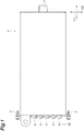
- FIG. 1 is a plan view of an exemplary module 1 including an adapter mounting structure 10 according to the first embodiment.
- FIG. 2 is a side view showing a side of the module 1 remote from the adapter mounting structure 10.
- the adapter mounting structure 10 is a structure for mounting, on a rack, a plurality of adapters 11 to which optical connectors are connected, by which the plurality of adapters 11 are held in an exposed state.
- the module 1 is a cassette-type device to be mounted on a rack in a data center and serves as an optical wiring module of the rack.
- the module 1 has a rectangular box shape extending in a first direction D1 corresponding to the longitudinal direction, a second direction D2 corresponding to the width direction, and a third direction D3 corresponding to the height direction.
- the adapter mounting structure 10 is provided at one end of the module 1 in the first direction D1.
- An adapter 3 is provided at the other end of the module 1 in the first direction D1.
- the adapter 3 is, for example, an MPO adapter to which an MPO connector is connected.
- the module 1 may be an MPO cassette that allows a plug- and-play connection between the MPO connector and each single-core connector.
- a plurality of optical waveguide members (such as optical cables) are laid inside the module 1.
- a multi-core MPO connector connected to the adapter 3 is optically connected to each of the plurality of optical waveguide members.
- Each of the plurality of optical waveguide members is optically connected to an optical connector connected to a corresponding one of the plurality of adapters 11.
- a 24-core MPO connector is connected to the adapter 3.
- 24 optical cables are laid inside the module 1, and each of the 24 optical cables is optically connected to an optical connector connected to a corresponding one of 24 adapters 11.
- the adapters 11 provided for 24 optical connectors are arranged in a grid pattern.
- the 24 adapters 11 include 12 pairs of adapters in total arranged in two rows (two rows of six pairs), each pair corresponding to two optical connectors (double optical connector), and each row including six pairs of adapters.
- each pair of adapters 11 is a double LC adapter, and the optical connector connected to each adapter 11 is an LC connector.
- the module 1 is an MPO cassette module in which each single-core LC connector and the multi-core MPO connector are optically connected to each other.
- the module 1 is mounted on each of a plurality of chassis to be attached to and detached from the rack, and includes a nylatch 2 to be fitted to the chassis.
- the module 1 may be mounted on the rack via a member (for example, an MPO cassette base) other than such a chassis.
- the nylatch 2 is provided at both ends of the adapter mounting structure 10 in the second direction D2, for example.
- FIG. 3 is a perspective view of the adapter mounting structure 10.
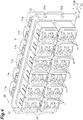
- FIG. 4 is a perspective view of the adapter mounting structure 10 with the first panel 20 removed.
- the adapter mounting structure 10 includes the first panel 20 anchored to the rack and exposed to the front side of the rack, and the second panel 30 located to the rear side of the rack.
- the first panel 20 is disposed to the front side of the rack relative to the second panel 30 and exposes the plurality of adapters 11 to the front side of the rack.
- the "front side” corresponds to one side in the first direction D1 (diagonally downward to the left in FIG. 3 ) and indicates a direction toward the outside of the rack when the adapter mounting structure 10 is mounted on the rack.
- the "rear side” corresponds to the other side in the first direction D1 (diagonally upward to the right in FIG. 3 ) and indicates a direction toward the inside of the rack when the adapter mounting structure 10 is mounted on the rack.
- the first panel 20 includes a front surface portion 21 that has a rectangular shape and exposes the adapters 11 and a first bent portion 22 bent toward the rear side of the rack.
- the front surface portion 21 includes, for example, a main body portion 21b having insertion holes 21a that extend in the second direction D2 and expose the plurality of adapters 11, and a pair of protruding portions 21c extending outward from the main body portion 21b in the second direction D2.
- the above-described nylatch 2 is inserted into the first panel 20 in the first direction D1, specifically, the nylatch 2 penetrates each protruding portion 21c of the front surface portion 21 in the first direction D1.
- the plurality of adapters 11 are arranged in, for example, a grid pattern in both the second direction D2 and the third direction D3.
- identification numbers X1, X2, X3, X4, X5, X6, X7, X8 for use in identifying each of the plurality of adapters 11 are printed.
- the identification number X1 denotes "1”
- the identification number X2 denotes “2”
- the identification number X3 denotes “3”
- the identification number X4 denotes "4"
- the identification number X5 denotes "21”
- the identification number X6 denotes "22”
- the identification number X7 denotes "23”
- the identification number X8 denotes "24”.
- each adapter 11 can be identified as follows, for example: an adapter 11 at the first place from both the left and top is identified as “1”, an adapter 11 at the first place from the right and the fourth place from the top is identified as “24”, and an adapter 11 at the third place from the left and the second place from the top is identified as "10".
- the mode of the identification numbers of the adapter mounting structure is not limited to the identification numbers X1 to X8 shown on the front surface portion 21 and can be changed as appropriate.
- the first panel 20 includes the first bent portion 22 bent in the first direction D1.
- the first bent portion 22 is bent from the main body portion 21b in the first direction D1. Accordingly, the first bent portion 22 is located inside the adapter mounting structure 10 in the second direction D2 relative to the protruding portions 21c. Note that the details of the first bent portion 22 will be described later.
- the second panel 30 is placed in, for example, a space defined by the front surface portion 21 and each first bent portion 22 of the first panel 20.
- the first panel 20 and the second panel 30 are anchored to each other with a plurality of screws N1.
- the second panel 30 anchors each of the plurality of adapters 11.
- a leaf spring 11a is provided on each adapter 11. When each adapter 11 is pressed against the second panel 30, the leaf spring 11a is expanded upward to be caught on the second panel 30. As a result, each adapter 11 is anchored to the second panel 30.
- a portion of each adapter 11 anchored to the adapter mounting structure 10 is provided to the rear side of the rack relative to the first panel 20.
- the second panel 30 includes a main body portion 31 to which each adapter 11 is anchored, and a second bent portion 32 bent in the first direction D1 from both ends of the main body portion 31 in the second direction D2.
- the second bent portion 32 is a portion bent along the first bent portion 22 of the first panel 20, specifically a portion bent in a direction opposite to the direction in which the first bent portion 22 extends (toward the front side of the rack).
- the second bent portion 32 is located inside the adapter mounting structure 10 in the second direction D2 relative to the first bent portion 22.
- the second bent portion 32 includes a screw hole 32a into which the screw N1 penetrating the first bent portion 22 is inserted.
- the second bent portion 32 includes, for example, a pair of the screw holes 32a aligned in the third direction D3.
- FIG. 5 is a perspective view of the first panel 20.
- FIG. 6 is a side view of the first panel 20 as viewed in the second direction D2.
- the above-described insertion hole 21a is formed in the front surface portion 21, and the insertion hole 21a penetrates in the first direction D1.
- the insertion hole 21a has, for example, a rectangular shape extending in the second direction D2.
- the front surface portion 21 includes two insertion holes 21a, and 12 adapters 11 (six double adapters) are inserted into each of the two insertion holes 21a.
- a notch portion 21e for use in determining the left-right direction (second direction) of the first panel 20 is formed on each insertion hole 21a.
- the notch portion 21e need not necessarily be formed on any portion of each insertion hole 21a in the left-right direction (second direction D2), and may be formed on any portion in the up-down direction (third direction D3). Note that when the notch portion 21e is formed on each of the plurality of insertion holes 21a, it is preferable to align the notch portions 21e in the same direction.
- the protruding portions 21c of the front surface portion 21 each include a through hole 21d through which the above-described nylatch 2 is inserted, and the through hole 21d penetrates in the first direction D1.
- the first bent portion 22 includes a pair of first side surface portions 23 extending from both ends of the front surface portion 21 in the left-right direction toward the rear side of the rack, a bottom surface portion 24 extending from a lower end of the front surface portion 21 toward the rear side of the rack, and a pair of second side surface portions 25 extending upward (third direction D3) from both ends of the bottom surface portion 24 in the left-right direction.
- the first side surface portion 23 extends in the first direction D1 below the protruding portions 21c.
- the first side surface portion 23 has, for example, a rectangular plate shape and includes a screw hole 23a penetrating in the second direction D2.
- the above-described screw N1 is inserted into the screw hole 23a from the outside of the first side surface portion 23 in the second direction D2.
- the bottom surface portion 24 extends from the lower end of the front surface portion 21 in the first direction D1, for example.
- the length of the bottom surface portion 24 in the first direction D1 is about twice the length of the first side surface portion 23 in the first direction D1.
- the bottom surface portion 24 is a portion facing the second panel 30 from below, and has a rectangular shape, for example.
- the second side surface portion 25 is provided behind the first side surface portion 23 of the bottom surface portion 24 (adjacent to the rear side of the rack).
- the second side surface portion 25 is bent in the third direction D3 (upward) from both the ends of the bottom surface portion 24 in the second direction D2.
- the second side surface portion 25 includes a rear portion 25a located behind the first side surface portion 23 and a front portion 25b extending forward (toward the front side of the rack) from the rear portion 25a and located above the first side surface portion 23.
- the rear portion 25a has a rectangular shape vertically extending in the third direction D3, and the front portion 25b has a rectangular shape extending forward from the upper side of the rear portion 25a.
- the first side surface portion 23 and the second side surface portion 25 are substantially the same in position in the second direction D2.
- the second side surface portion 25 may be flush with the first side surface portion 23.
- a cutout portion 26 is provided between the first side surface portion 23 and the second side surface portion 25.
- the cutout portion 26 includes a first cutout portion 26a located between the front portion 25b and the front surface portion 21, a second cutout portion 26b located between the front portion 25b and the first side surface portion 23, and a third cutout portion 26c located between the rear portion 25a and the first side surface portion 23.
- the first cutout portion 26a, the second cutout portion 26b, and the third cutout portion 26c continuous in this order.
- the first cutout portion 26a extends downward on the rear side of the front surface portion 21, the second cutout portion 26b extends rearward from the lower end of the first cutout portion 26a, and the third cutout portion 26c extends from the rear end of the second cutout portion 26b to the bottom surface portion 24.
- the front portion 25b of the second side surface portion 25 includes a screw hole 25d penetrating in the second direction D2.
- the above-described screw N1 is inserted into the screw hole 25d from the outside of the second side surface portion 25 in the second direction D2.
- the screw hole 25d is provided above the above-described screw hole 23a of the first side surface portion 23, and, for example, the screw hole 23a and the screw hole 25d are arranged in the third direction D3. Screwing the screws N1 through the screw hole 23a and the screw hole 25d into the above-described screw holes 32a of the second bent portion 32 causes the first panel 20 and the second panel 30 to be anchored to each other.
- FIG. 7 is a front view of the second panel 30 as viewed from front (the front side of the rack).
- FIG. 8 is a perspective view of the second panel 30.
- the main body portion 31 includes, for example, a plurality of insertion holes 31a that penetrate in the first direction D1 and through which the adapters 11 are inserted in the first direction D1.
- the main body portion 31 includes 12 insertion holes 31a (two rows of six holes) through which each pair of the adapters 11 (double adapters) vertically aligned is inserted.
- Each insertion hole 31a has, for example, a rectangular shape.
- a notch portion 31b for use in determining the left-right direction of the second panel 30 may be formed.
- the notch portion 31b need not necessarily be formed on any portion of the insertion hole 31a in the left-right direction (second direction D2), and may be formed on any portion in the up-down direction (third direction D3). Note that when the notch portion 31b is formed on each of the plurality of insertion holes 31a, it is preferable to align the notch portions 31b in the same direction.
- a slit portion 33 extending in the third direction D3 is formed between the second bent portion 32 and the main body portion 31.
- a pair of the slit portions 33 are provided on both the ends of the main body portion 31 in the second direction D2.
- Each slit portion 33 extends in the third direction D3.
- the pair of screw holes 32a aligned in the third direction D3 in the second bent portion 32 are provided corresponding to the above-described screw hole 25d and screw hole 23a.
- the upper screw hole 32a coincides in position with the screw hole 25d of the second side surface portion 25, and the lower screw hole 32a coincides in position with the screw hole 23a of the first side surface portion 23.
- the screw N1 is screwed into the screw hole 25d and the screw hole 32a with the screw hole 25d located outside the upper screw hole 32a in the second direction D2.
- screwing, with the screw hole 23a located outside the lower screw hole 32a in the second direction D2 the screw N1 into the screw hole 23a and the screw hole 32a causes the first panel 20 and the second panel 30 to be anchored to each other.
- the adapter mounting structure 10 includes the first panel 20 anchored to the rack and configured to expose the adapters, and the second panel 30 anchored to the first panel 20 and configured to anchor the adapters 11.
- the adapter mounting structure 10 includes the first panel 20 located adjacent to the front side of the rack and the second panel 30 located adjacent to the rear side of the rack, and each of the plurality of adapters 11 is mounted on the two panels integrated into a single panel. Therefore, the use of such two panels, the first panel 20 and the second panel 30, integrated into a single panel makes it possible to increase strength and in turn makes it possible to suppress deformation in the panels.
- Each of the plurality of adapters 11 is exposed from the first panel 20 to the front side of the rack and is anchored to the second panel 30 located to the rear side of the rack relative to the first panel 20. Therefore, anchoring each adapter 11 to the second panel 30 located to the rear side of the rack makes it possible to reduce the protrusion amount of the adapter 11 from the first panel 20. For example, even when the adapter mounting structure 10 has the identification numbers X1 to X8 for use in identifying each adapter 11, the reduction in the protrusion amount of each adapter 11 makes the identification numbers X1 to X8 clearly visible.
- the first panel 20 may include the first bent portion 22 bent toward the rear side of the rack. This structure where the first panel 20 includes the first bent portion 22 bent toward the rear side of the rack can increase strength of the first panel 20. It is therefore possible to more reliably suppress deformation in the first panel 20 caused by the connection of the optical connectors to the adapters 11 or the like.
- the second panel 30 may include the second bent portion 32 bent along the first bent portion 22.
- This structure where the second panel 30 configured to anchor the plurality of adapters 11 includes the second bent portion 32 can increase strength of the second panel 30. It is therefore possible to more reliably suppress deformation in the second panel 30 caused by the application of an external force to the adapters 11.
- the first panel 20 may include the front surface portion 21 that exposes the adapters 11.
- the first bent portion 22 may include the pair of first side surface portions 23 extending from both the ends of the front surface portion 21 in the left-right direction toward the rear side of the rack, and the bottom surface portion 24 extending from the lower end of the front surface portion 21 toward the rear side of the rack. This structure where the first bent portion 22 includes the pair of the first side surface portion 23 and the bottom surface portion 24 can further increase the strength of the first panel 20. This in turn makes it possible to more reliably suppress deformation in the first panel 20.
- the first bent portion 22 may further include the pair of second side surface portions 25 extending upward from both the ends of the bottom surface portion 24 in the left-right direction. This structure where the first bent portion 22 further includes the second side surface portions 25 can more reliably suppress deformation caused by the connection of the optical connectors or the like.
- the first side surface portions 23 and the second side surface portions 25 may be each screwed to the second panel 30.
- This structure where the first side surface portions 23 and second side surface portions 25 of the first panel 20 are each screwed to the second panel 30 allows the first panel 20 and the second panel 30 to be anchored to each other more tightly, and can eliminate the need of sheet-metal welding or the like between the first panel 20 and the second panel 30. That is, the first panel 20 and the second panel 30 can be tightly anchored to each other by screwing, thereby making it possible to eliminate the need of anchoring by sheet-metal welding or the like. It is therefore possible to eliminate the cost of sheet-metal welding or the like and to enhance finished appearances of the first panel 20 and the second panel 30.
- the adapter mounting structure 40 includes a first panel 50 and a second panel 60 that are different in shape from the first panel 20 and the second panel 30, respectively.
- any redundant description that has been already given for the first embodiment will be omitted as appropriate.
- the first panel 50 includes, for example, a front surface portion 51 similar to the front surface portion 21, and a first bent portion 52 bent from a lower end of the front surface portion 51 toward the rear side of the rack.
- the second panel 60 includes a main body portion 61 similar to the main body portion 31 to which each adapter 11 is anchored, and a second bent portion 62 bent from a lower end of the main body portion 61 toward the rear side of the rack. Both the first bent portion 52 and the second bent portion 62 extend, farther than the adapters 11, toward the rear side of the rack, and the second bent portion 62 is placed on an upper surface 52a of the first bent portion 52.
- the first bent portion 52 and the second bent portion 62 each have a screw hole into which a screw N2 is screwed. Screwing the screw N2 into the screw hole of the first bent portion 52 and the screw hole of the second bent portion 62 causes the first panel 50 and the second panel 60 to be anchored to each other.
- the first bent portion 52 and the second bent portion 62 are anchored to each other with a pair of screws N2 aligned in the second direction D2.
- the pair of screws N2 are provided at positions equally spaced apart from a center of the adapter mounting structure 40 in the second direction D2.
- each of the plurality of adapters 11 is mounted on the two panels (the first panel 50 and the second panel 60) integrated into a single panel, it is possible to suppress deformation in the panels. Further, anchoring each adapter 11 to the second panel 60 located to the rear side of the rack makes it possible to reduce the protrusion amount of the adapter 11 from the first panel 50. Accordingly, this makes the identification numbers X1 to X8 clearly visible.
- the first panel 50 may include the first bent portion 52 bent toward the rear side of the rack. This makes it possible to increase strength of the first panel 50, and to more reliably suppress deformation in the first panel 50 caused by the connection of the optical connectors to the adapters 11 or the like.
- the second panel 60 may include the second bent portion 62 bent toward the rear side of the rack. This makes it possible to increase strength of the second panel 60, and to more reliably suppress deformation in the second panel 60 caused by the application of an external force to the adapters 11.
- the adapter mounting structure 10 provided in the module 1 has been described.
- the shape, size, and mounting mode to the rack of the module to which the adapter mounting structure is mounted are not limited to the shape, size, and mounting mode of the above-described module 1, and can be changed as appropriate. That is, the adapter mounting structure 10 can be used as an adapter panel that is not provided on the module 1 but is anchored alone to a rack or the like.
- the module 1 that is an MPO cassette module in which each single-core LC connector and a multi-core MPO connector are optically connected to each other has been described.
- the standard on the optical connectors to which the module is connected is not limited to LC or MPO and can be changed as appropriate.
Landscapes
- Physics & Mathematics (AREA)
- General Physics & Mathematics (AREA)
- Optics & Photonics (AREA)
- Engineering & Computer Science (AREA)
- Computer Hardware Design (AREA)
- General Engineering & Computer Science (AREA)
- Microelectronics & Electronic Packaging (AREA)
- Mechanical Coupling Of Light Guides (AREA)
- Light Guides In General And Applications Therefor (AREA)
Abstract
Description
- An aspect of the disclosure relates to an adapter mounting structure.
- This application claims the priority based on
Japanese Patent Application No. 2018-199436 filed on October 23, 2018 -
Patent Literature 1 discloses an adapter panel mounting structure in which a plurality of optical adapters for connecting optical cords are mounted. In the adapter panel mounting structure, two adapter panels arranged side by side are each mounted on a front end of a chassis. The adapter panels have a plate shape extending along a front panel of the chassis. The adapter panels each include a latch that fits into a mounting hole formed in the front panel of the chassis, and a claw-shaped protrusion to be engaged with a locking member located at a center of the front panel in the left-right direction. Fitting the latch into the mounting hole and causing the claw-shaped protrusion to engage with the locking member causes the adapter panel to be mounted on the chassis. The latch is provided at one end of each adapter panel in the left-right direction, and the claw-shaped protrusion is provided at the other end of the adapter panel in the left-right direction. -
Patent Literature 2 discloses an optical connector connection panel. The optical connector connection panel is mounted on a plurality of mount angles (supports) arranged vertically inside a rack. The optical connector connection panel includes a panel body having a rectangular box shape. An adapter panel to which a plurality of optical adapters are anchored is mounted on a front surface of the panel body. In the adapter panel, the plurality of optical adapters are arranged in a grid pattern, and the adapter panel has a rectangular shape extending horizontally. -
- Patent Literature 1:
Japanese Unexamined Patent Publication No. 2009-294531 - Patent Literature 2:
Japanese Unexamined Patent Publication No. 2003-29055 - An adapter mounting structure according to an aspect of the present disclosure is an adapter mounting structure for mounting, on a rack, a plurality of adapters to which optical connectors are connected. The adapter mounting structure includes a first panel configured to expose, to a front side of the rack, the plurality of adapters and anchored to the rack, and a second panel disposed to a rear side of the rack relative to the first panel, the second panel being anchored to the first panel and being configured to anchor each of the plurality of adapters.
-
-
FIG. 1 is a diagram showing an example of a module including an adapter mounting structure according to the first embodiment. -
FIG. 2 is a rear view of the module shown inFIG. 1 . -
FIG. 3 is a perspective view of the adapter mounting structure shown inFIG. 1 . -
FIG. 4 is a perspective view of the adapter mounting structure shown inFIG. 3 with a first panel removed. -
FIG. 5 is a perspective view of the first panel of the adapter mounting structure shown inFIG. 3 . -
FIG. 6 is a side view of the first panel shown inFIG. 5 . -
FIG. 7 is a front view of a second panel of the adapter mounting structure shown inFIG. 3 . -
FIG. 8 is a perspective view of the second panel shown inFIG. 7 . -
FIG. 9 is a perspective view of an adapter mounting structure according to the second embodiment. -
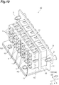
FIG. 10 is a perspective view of the adapter mounting structure shown inFIG. 9 as viewed in a direction different from the direction inFIG. 9 . - Each of the above-described adapter panels has a plate shape, and a plurality of adapters are mounted on the adapter panel having a plate shape. An optical connector is connected to each of the plurality of adapters. When an adapter panel has a plate shape, there is a concern that the adapter panel may bend due to the connection of the optical connector to the adapter. In particular, when the number of adapters mounted on the adapter panel is large, and a plurality of adapters are highly densely arranged on the adapter panel, there is a concern that the adapter panel may be deformed when, for example, the optical connector is connected to the adapter.
- In each of the above-described adapter panels, a plurality of adapters protrude from the adapter panel. When the number of adapters mounted on the adapter panel is large, the adapter panel may be provided with identification numbers for use in identifying each of the plurality of adapters. At this time, when the protrusion amount of the adapters from the adapter panel is large, there is a concern that the above-described identification numbers may be difficult to see due to the protrusion of the adapters. Therefore, it is required to suppress deformation in the adapter panel and to reduce the protrusion amount of the adapters.
- One aspect of the present disclosure is to provide an adapter mounting structure that can suppress deformation and reduce the protrusion amount of the adapter.
- According to the present disclosure, it is possible to suppress deformation and reduce the protrusion amount of the adapters.
- First, descriptions will be given in series of the contents of embodiments of the present disclosure. An adapter mounting structure according to an embodiment is an adapter mounting structure for mounting, on a rack, a plurality of adapters to which optical connectors are connected. The adapter mounting structure includes a first panel including insertion holes through which a plurality of adapters are inserted, the first panel being configured to expose, to a front side of the rack, the plurality of adapters thus inserted and being anchored to the rack, and a second panel disposed to the rear side of the rack relative to the first panel, the second panel being anchored to the first panel and being configured to anchor each of the plurality of adapters.
- The adapter mounting structure according to the embodiment includes the first panel anchored to the rack and configured to expose the adapters, and the second panel anchored to the first panel and configured to anchor the adapters. The adapter mounting structure includes the first panel located adjacent to the front side of the rack and the second panel located adjacent to the rear side of the rack, and each of the plurality of adapters is mounted on the two panels integrated into a single panel. Therefore, the use of such two panels makes it possible to increase strength and in turn makes it possible to suppress deformation in the panels. Each of the plurality of adapters is exposed from the first panel to the front side of the rack and is anchored to the second panel located adjacent to the rear side of the rack relative to the first panel. Anchoring each adapter to the second panel located adjacent to the rear side of the rack makes it possible to reduce the protrusion amount of the adapters from the first panel. For example, even when the adapter mounting structure has an identification number for use in identifying each adapter, the reduction in the protrusion amount of the adapters makes the identification number clearly visible.
- In the adapter mounting structure according to the embodiment, the first panel may include a first bent portion bent toward the rear side of the rack. This structure where the first panel includes the first bent portion bent toward the rear side of the rack can increase strength of the first panel. It is therefore possible to more reliably suppress deformation in the first panel caused by the connection of the optical connectors to the adapters or the like.
- In the adapter mounting structure according to the embodiment, the second panel may include a second bent portion bent along the first bent portion. This structure where the second panel configured to anchor the plurality of adapters include the second bent portion can increase strength of the second panel. It is therefore possible to more reliably suppress deformation in the second panel caused by the application of an external force to the adapters.
- In the adapter mounting structure according to the embodiment, the first panel may include a front surface portion configured to expose the adapters. The first bent portion may include a pair of first side surface portions extending from both ends of the front surface portion in the left-right direction toward the rear side of the rack, and a bottom surface portion extending from a lower end of the front surface portion toward the rear side of the rack. This structure where the first bent portion includes the pair of the first side surface portions and the bottom surface portion can further increase the strength of the first panel. This in turn makes it possible to more reliably suppress deformation in the first panel.
- In the adapter mounting structure according to the embodiment, the first bent portion may further include a pair of second side surface portions extending upward from both ends of the bottom surface portion in the left-right direction. This structure where the first bent portion further includes the second side surface portions can more reliably suppress deformation caused by the connection of the optical connectors or the like.
- In the adapter mounting structure according to the embodiment, the first side surface portions and the second side surface portions may be each screwed to the second panel. This structure where the first side surface portions and second side surface portions of the first panel are each screwed to the second panel allows the first panel and the second panel to be anchored to each other more tightly, and can reduce the need of sheet-metal welding or the like between the first panel and the second panel and the like. It is therefore possible to reduce the cost of sheet-metal welding or the like and to enhance finished appearances of the first panel and the second panel.
- A description will be given of specific examples of the adapter mounting structure according to the embodiments of the present disclosure with reference to the drawings. It should be noted that the present disclosure is not limited to the following specific examples, and is intended to be defined by the claims and to include all modifications within the scope of the claims and their equivalents. In the following description, the same or equivalent components are denoted by the same reference numerals, and any redundant description will be omitted as appropriate.
-
FIG. 1 is a plan view of anexemplary module 1 including anadapter mounting structure 10 according to the first embodiment.FIG. 2 is a side view showing a side of themodule 1 remote from theadapter mounting structure 10. Theadapter mounting structure 10 is a structure for mounting, on a rack, a plurality ofadapters 11 to which optical connectors are connected, by which the plurality ofadapters 11 are held in an exposed state. As an example, themodule 1 is a cassette-type device to be mounted on a rack in a data center and serves as an optical wiring module of the rack. Themodule 1 has a rectangular box shape extending in a first direction D1 corresponding to the longitudinal direction, a second direction D2 corresponding to the width direction, and a third direction D3 corresponding to the height direction. - The
adapter mounting structure 10 is provided at one end of themodule 1 in the first direction D1. Anadapter 3 is provided at the other end of themodule 1 in the first direction D1. Theadapter 3 is, for example, an MPO adapter to which an MPO connector is connected. In this case, themodule 1 may be an MPO cassette that allows a plug- and-play connection between the MPO connector and each single-core connector. For example, a plurality of optical waveguide members (such as optical cables) are laid inside themodule 1. A multi-core MPO connector connected to theadapter 3 is optically connected to each of the plurality of optical waveguide members. - Each of the plurality of optical waveguide members is optically connected to an optical connector connected to a corresponding one of the plurality of
adapters 11. As an example, a 24-core MPO connector is connected to theadapter 3. For example, 24 optical cables are laid inside themodule 1, and each of the 24 optical cables is optically connected to an optical connector connected to a corresponding one of 24adapters 11. In theadapter mounting structure 10, for example, theadapters 11 provided for 24 optical connectors are arranged in a grid pattern. For example, the 24adapters 11 include 12 pairs of adapters in total arranged in two rows (two rows of six pairs), each pair corresponding to two optical connectors (double optical connector), and each row including six pairs of adapters. For example, each pair ofadapters 11 is a double LC adapter, and the optical connector connected to eachadapter 11 is an LC connector. In this case, themodule 1 is an MPO cassette module in which each single-core LC connector and the multi-core MPO connector are optically connected to each other. - For example, the
module 1 is mounted on each of a plurality of chassis to be attached to and detached from the rack, and includes anylatch 2 to be fitted to the chassis. Note that themodule 1 may be mounted on the rack via a member (for example, an MPO cassette base) other than such a chassis. Thenylatch 2 is provided at both ends of theadapter mounting structure 10 in the second direction D2, for example. -
FIG. 3 is a perspective view of theadapter mounting structure 10.FIG. 4 is a perspective view of theadapter mounting structure 10 with thefirst panel 20 removed. As shown inFIGS. 3 and4 , theadapter mounting structure 10 includes thefirst panel 20 anchored to the rack and exposed to the front side of the rack, and thesecond panel 30 located to the rear side of the rack. - As shown in
FIG. 3 , thefirst panel 20 is disposed to the front side of the rack relative to thesecond panel 30 and exposes the plurality ofadapters 11 to the front side of the rack. Herein, the "front side" corresponds to one side in the first direction D1 (diagonally downward to the left inFIG. 3 ) and indicates a direction toward the outside of the rack when theadapter mounting structure 10 is mounted on the rack. The "rear side" corresponds to the other side in the first direction D1 (diagonally upward to the right inFIG. 3 ) and indicates a direction toward the inside of the rack when theadapter mounting structure 10 is mounted on the rack. - The
first panel 20 includes afront surface portion 21 that has a rectangular shape and exposes theadapters 11 and a firstbent portion 22 bent toward the rear side of the rack. Thefront surface portion 21 includes, for example, amain body portion 21b havinginsertion holes 21a that extend in the second direction D2 and expose the plurality ofadapters 11, and a pair of protrudingportions 21c extending outward from themain body portion 21b in the second direction D2. The above-describednylatch 2 is inserted into thefirst panel 20 in the first direction D1, specifically, thenylatch 2 penetrates each protrudingportion 21c of thefront surface portion 21 in the first direction D1. - On the
front surface portion 21, the plurality ofadapters 11 are arranged in, for example, a grid pattern in both the second direction D2 and the third direction D3. On thefront surface portion 21, for example, identification numbers X1, X2, X3, X4, X5, X6, X7, X8 for use in identifying each of the plurality ofadapters 11 are printed. As an example, the identification number X1 denotes "1", the identification number X2 denotes "2", the identification number X3 denotes "3", the identification number X4 denotes "4", the identification number X5 denotes "21", and the identification number X6 denotes "22", the identification number X7 denotes "23", and the identification number X8 denotes "24". - This allows each
adapter 11 to be identified as follows, for example: anadapter 11 at the first place from both the left and top is identified as "1", anadapter 11 at the first place from the right and the fourth place from the top is identified as "24", and anadapter 11 at the third place from the left and the second place from the top is identified as "10". Note that the mode of the identification numbers of the adapter mounting structure is not limited to the identification numbers X1 to X8 shown on thefront surface portion 21 and can be changed as appropriate. - The
first panel 20 includes the firstbent portion 22 bent in the first direction D1. For example, the firstbent portion 22 is bent from themain body portion 21b in the first direction D1. Accordingly, the firstbent portion 22 is located inside theadapter mounting structure 10 in the second direction D2 relative to the protrudingportions 21c. Note that the details of the firstbent portion 22 will be described later. - The
second panel 30 is placed in, for example, a space defined by thefront surface portion 21 and each firstbent portion 22 of thefirst panel 20. Thefirst panel 20 and thesecond panel 30 are anchored to each other with a plurality of screws N1. Thesecond panel 30 anchors each of the plurality ofadapters 11. Aleaf spring 11a is provided on eachadapter 11. When eachadapter 11 is pressed against thesecond panel 30, theleaf spring 11a is expanded upward to be caught on thesecond panel 30. As a result, eachadapter 11 is anchored to thesecond panel 30. A portion of eachadapter 11 anchored to theadapter mounting structure 10 is provided to the rear side of the rack relative to thefirst panel 20. - As shown in
FIGS. 3 and4 , thesecond panel 30 includes amain body portion 31 to which eachadapter 11 is anchored, and a secondbent portion 32 bent in the first direction D1 from both ends of themain body portion 31 in the second direction D2. The secondbent portion 32 is a portion bent along the firstbent portion 22 of thefirst panel 20, specifically a portion bent in a direction opposite to the direction in which the firstbent portion 22 extends (toward the front side of the rack). The secondbent portion 32 is located inside theadapter mounting structure 10 in the second direction D2 relative to the firstbent portion 22. The secondbent portion 32 includes ascrew hole 32a into which the screw N1 penetrating the firstbent portion 22 is inserted. The secondbent portion 32 includes, for example, a pair of thescrew holes 32a aligned in the third direction D3. -
FIG. 5 is a perspective view of thefirst panel 20.FIG. 6 is a side view of thefirst panel 20 as viewed in the second direction D2. As shown inFIGS. 5 and6 , the above-describedinsertion hole 21a is formed in thefront surface portion 21, and theinsertion hole 21a penetrates in the first direction D1. Theinsertion hole 21a has, for example, a rectangular shape extending in the second direction D2. As an example, thefront surface portion 21 includes twoinsertion holes 21a, and 12 adapters 11 (six double adapters) are inserted into each of the twoinsertion holes 21a. Anotch portion 21e for use in determining the left-right direction (second direction) of thefirst panel 20 is formed on eachinsertion hole 21a. Thenotch portion 21e need not necessarily be formed on any portion of eachinsertion hole 21a in the left-right direction (second direction D2), and may be formed on any portion in the up-down direction (third direction D3). Note that when thenotch portion 21e is formed on each of the plurality ofinsertion holes 21a, it is preferable to align thenotch portions 21e in the same direction. - The protruding
portions 21c of thefront surface portion 21 each include a throughhole 21d through which the above-describednylatch 2 is inserted, and the throughhole 21d penetrates in the first direction D1. The firstbent portion 22 includes a pair of firstside surface portions 23 extending from both ends of thefront surface portion 21 in the left-right direction toward the rear side of the rack, abottom surface portion 24 extending from a lower end of thefront surface portion 21 toward the rear side of the rack, and a pair of secondside surface portions 25 extending upward (third direction D3) from both ends of thebottom surface portion 24 in the left-right direction. - The first
side surface portion 23 extends in the first direction D1 below the protrudingportions 21c. The firstside surface portion 23 has, for example, a rectangular plate shape and includes ascrew hole 23a penetrating in the second direction D2. The above-described screw N1 is inserted into thescrew hole 23a from the outside of the firstside surface portion 23 in the second direction D2. Thebottom surface portion 24 extends from the lower end of thefront surface portion 21 in the first direction D1, for example. For example, the length of thebottom surface portion 24 in the first direction D1 is about twice the length of the firstside surface portion 23 in the first direction D1. - The
bottom surface portion 24 is a portion facing thesecond panel 30 from below, and has a rectangular shape, for example. The secondside surface portion 25 is provided behind the firstside surface portion 23 of the bottom surface portion 24 (adjacent to the rear side of the rack). The secondside surface portion 25 is bent in the third direction D3 (upward) from both the ends of thebottom surface portion 24 in the second direction D2. The secondside surface portion 25 includes arear portion 25a located behind the firstside surface portion 23 and afront portion 25b extending forward (toward the front side of the rack) from therear portion 25a and located above the firstside surface portion 23. - For example, the
rear portion 25a has a rectangular shape vertically extending in the third direction D3, and thefront portion 25b has a rectangular shape extending forward from the upper side of therear portion 25a. For example, the firstside surface portion 23 and the secondside surface portion 25 are substantially the same in position in the second direction D2. The secondside surface portion 25 may be flush with the firstside surface portion 23. - For example, a
cutout portion 26 is provided between the firstside surface portion 23 and the secondside surface portion 25. Thecutout portion 26 includes afirst cutout portion 26a located between thefront portion 25b and thefront surface portion 21, asecond cutout portion 26b located between thefront portion 25b and the firstside surface portion 23, and athird cutout portion 26c located between therear portion 25a and the firstside surface portion 23. Thefirst cutout portion 26a, thesecond cutout portion 26b, and thethird cutout portion 26c continuous in this order. Thefirst cutout portion 26a extends downward on the rear side of thefront surface portion 21, thesecond cutout portion 26b extends rearward from the lower end of thefirst cutout portion 26a, and thethird cutout portion 26c extends from the rear end of thesecond cutout portion 26b to thebottom surface portion 24. - The
front portion 25b of the secondside surface portion 25 includes ascrew hole 25d penetrating in the second direction D2. The above-described screw N1 is inserted into thescrew hole 25d from the outside of the secondside surface portion 25 in the second direction D2. Thescrew hole 25d is provided above the above-describedscrew hole 23a of the firstside surface portion 23, and, for example, thescrew hole 23a and thescrew hole 25d are arranged in the third direction D3. Screwing the screws N1 through thescrew hole 23a and thescrew hole 25d into the above-describedscrew holes 32a of the secondbent portion 32 causes thefirst panel 20 and thesecond panel 30 to be anchored to each other. -
FIG. 7 is a front view of thesecond panel 30 as viewed from front (the front side of the rack).FIG. 8 is a perspective view of thesecond panel 30. As shown inFIGS. 7 and8 , themain body portion 31 includes, for example, a plurality ofinsertion holes 31a that penetrate in the first direction D1 and through which theadapters 11 are inserted in the first direction D1. As an example, themain body portion 31 includes 12insertion holes 31a (two rows of six holes) through which each pair of the adapters 11 (double adapters) vertically aligned is inserted. Eachinsertion hole 31a has, for example, a rectangular shape. On eachinsertion hole 31a, anotch portion 31b for use in determining the left-right direction of thesecond panel 30 may be formed. Thenotch portion 31b need not necessarily be formed on any portion of theinsertion hole 31a in the left-right direction (second direction D2), and may be formed on any portion in the up-down direction (third direction D3). Note that when thenotch portion 31b is formed on each of the plurality ofinsertion holes 31a, it is preferable to align thenotch portions 31b in the same direction. - A
slit portion 33 extending in the third direction D3 is formed between the secondbent portion 32 and themain body portion 31. For example, a pair of theslit portions 33 are provided on both the ends of themain body portion 31 in the second direction D2. Eachslit portion 33 extends in the third direction D3. When the secondbent portion 32 is formed by bending, making the secondbent portion 32 flexible along theslit portion 33 makes it possible to prevent deformation in thescrew hole 32a located in the vicinity of the bent portion. The pair ofscrew holes 32a aligned in the third direction D3 in the secondbent portion 32 are provided corresponding to the above-describedscrew hole 25d and screwhole 23a. - Specifically, in the first direction D1 and the third direction D3, the
upper screw hole 32a coincides in position with thescrew hole 25d of the secondside surface portion 25, and thelower screw hole 32a coincides in position with thescrew hole 23a of the firstside surface portion 23. As a result, the screw N1 is screwed into thescrew hole 25d and thescrew hole 32a with thescrew hole 25d located outside theupper screw hole 32a in the second direction D2. Then, screwing, with thescrew hole 23a located outside thelower screw hole 32a in the second direction D2, the screw N1 into thescrew hole 23a and thescrew hole 32a causes thefirst panel 20 and thesecond panel 30 to be anchored to each other. - Next, a description will be given in detail of the action and effect of the above-described
adapter mounting structure 10 according to the first embodiment. For example, as shown inFIG. 3 , theadapter mounting structure 10 includes thefirst panel 20 anchored to the rack and configured to expose the adapters, and thesecond panel 30 anchored to thefirst panel 20 and configured to anchor theadapters 11. Theadapter mounting structure 10 includes thefirst panel 20 located adjacent to the front side of the rack and thesecond panel 30 located adjacent to the rear side of the rack, and each of the plurality ofadapters 11 is mounted on the two panels integrated into a single panel. Therefore, the use of such two panels, thefirst panel 20 and thesecond panel 30, integrated into a single panel makes it possible to increase strength and in turn makes it possible to suppress deformation in the panels. - Each of the plurality of
adapters 11 is exposed from thefirst panel 20 to the front side of the rack and is anchored to thesecond panel 30 located to the rear side of the rack relative to thefirst panel 20. Therefore, anchoring eachadapter 11 to thesecond panel 30 located to the rear side of the rack makes it possible to reduce the protrusion amount of theadapter 11 from thefirst panel 20. For example, even when theadapter mounting structure 10 has the identification numbers X1 to X8 for use in identifying eachadapter 11, the reduction in the protrusion amount of eachadapter 11 makes the identification numbers X1 to X8 clearly visible. - The
first panel 20 may include the firstbent portion 22 bent toward the rear side of the rack. This structure where thefirst panel 20 includes the firstbent portion 22 bent toward the rear side of the rack can increase strength of thefirst panel 20. It is therefore possible to more reliably suppress deformation in thefirst panel 20 caused by the connection of the optical connectors to theadapters 11 or the like. - The
second panel 30 may include the secondbent portion 32 bent along the firstbent portion 22. This structure where thesecond panel 30 configured to anchor the plurality ofadapters 11 includes the secondbent portion 32 can increase strength of thesecond panel 30. It is therefore possible to more reliably suppress deformation in thesecond panel 30 caused by the application of an external force to theadapters 11. - The
first panel 20 may include thefront surface portion 21 that exposes theadapters 11. The firstbent portion 22 may include the pair of firstside surface portions 23 extending from both the ends of thefront surface portion 21 in the left-right direction toward the rear side of the rack, and thebottom surface portion 24 extending from the lower end of thefront surface portion 21 toward the rear side of the rack. This structure where the firstbent portion 22 includes the pair of the firstside surface portion 23 and thebottom surface portion 24 can further increase the strength of thefirst panel 20. This in turn makes it possible to more reliably suppress deformation in thefirst panel 20. - The first
bent portion 22 may further include the pair of secondside surface portions 25 extending upward from both the ends of thebottom surface portion 24 in the left-right direction. This structure where the firstbent portion 22 further includes the secondside surface portions 25 can more reliably suppress deformation caused by the connection of the optical connectors or the like. - The first
side surface portions 23 and the secondside surface portions 25 may be each screwed to thesecond panel 30. This structure where the firstside surface portions 23 and secondside surface portions 25 of thefirst panel 20 are each screwed to thesecond panel 30 allows thefirst panel 20 and thesecond panel 30 to be anchored to each other more tightly, and can eliminate the need of sheet-metal welding or the like between thefirst panel 20 and thesecond panel 30. That is, thefirst panel 20 and thesecond panel 30 can be tightly anchored to each other by screwing, thereby making it possible to eliminate the need of anchoring by sheet-metal welding or the like. It is therefore possible to eliminate the cost of sheet-metal welding or the like and to enhance finished appearances of thefirst panel 20 and thesecond panel 30. - Next, a description will be given of an
adapter mounting structure 40 according to the second embodiment with reference toFIGS. 9 and10 . As shown inFIGS. 9 and10 , theadapter mounting structure 40 includes afirst panel 50 and asecond panel 60 that are different in shape from thefirst panel 20 and thesecond panel 30, respectively. In the following description, any redundant description that has been already given for the first embodiment will be omitted as appropriate. - The
first panel 50 includes, for example, afront surface portion 51 similar to thefront surface portion 21, and a firstbent portion 52 bent from a lower end of thefront surface portion 51 toward the rear side of the rack. Thesecond panel 60 includes amain body portion 61 similar to themain body portion 31 to which eachadapter 11 is anchored, and a secondbent portion 62 bent from a lower end of themain body portion 61 toward the rear side of the rack. Both the firstbent portion 52 and the secondbent portion 62 extend, farther than theadapters 11, toward the rear side of the rack, and the secondbent portion 62 is placed on anupper surface 52a of the firstbent portion 52. - The first
bent portion 52 and the secondbent portion 62 each have a screw hole into which a screw N2 is screwed. Screwing the screw N2 into the screw hole of the firstbent portion 52 and the screw hole of the secondbent portion 62 causes thefirst panel 50 and thesecond panel 60 to be anchored to each other. For example, the firstbent portion 52 and the secondbent portion 62 are anchored to each other with a pair of screws N2 aligned in the second direction D2. As an example, the pair of screws N2 are provided at positions equally spaced apart from a center of theadapter mounting structure 40 in the second direction D2. - As described above, in the
adapter mounting structure 40 according to the second embodiment, since each of the plurality ofadapters 11 is mounted on the two panels (thefirst panel 50 and the second panel 60) integrated into a single panel, it is possible to suppress deformation in the panels. Further, anchoring eachadapter 11 to thesecond panel 60 located to the rear side of the rack makes it possible to reduce the protrusion amount of theadapter 11 from thefirst panel 50. Accordingly, this makes the identification numbers X1 to X8 clearly visible. - The
first panel 50 may include the firstbent portion 52 bent toward the rear side of the rack. This makes it possible to increase strength of thefirst panel 50, and to more reliably suppress deformation in thefirst panel 50 caused by the connection of the optical connectors to theadapters 11 or the like. Thesecond panel 60 may include the secondbent portion 62 bent toward the rear side of the rack. This makes it possible to increase strength of thesecond panel 60, and to more reliably suppress deformation in thesecond panel 60 caused by the application of an external force to theadapters 11. - The embodiments of the adapter mounting structure according to the present disclosure have been described above. However, the present invention is not limited to the above-described embodiments and the above-described examples, and various modifications can be made without departing from the gist described in the claims. That is, the shape, size, and arrangement mode of each portion of the first panel and second panel of the adapter mounting structure can be changed as appropriate without departing from the above gist.
- For example, in the above-described embodiment, the
adapter mounting structure 10 provided in themodule 1 has been described. However, the shape, size, and mounting mode to the rack of the module to which the adapter mounting structure is mounted are not limited to the shape, size, and mounting mode of the above-describedmodule 1, and can be changed as appropriate. That is, theadapter mounting structure 10 can be used as an adapter panel that is not provided on themodule 1 but is anchored alone to a rack or the like. Further, in the above-described embodiment, themodule 1 that is an MPO cassette module in which each single-core LC connector and a multi-core MPO connector are optically connected to each other has been described. However, the standard on the optical connectors to which the module is connected is not limited to LC or MPO and can be changed as appropriate. -
- 1
- module
- 2
- nylatch
- 3
- adapter
- 10, 40
- adapter mounting structure
- 11
- adapter
- 11a
- leaf spring
- 20, 50
- first panel
- 21, 51
- front surface portion
- 21a
- insertion hole
- 21b
- main body portion
- 21c
- protruding portion
- 21d
- through hole
- 21e
- notch portion
- 22, 52
- first bent portion
- 23
- first side surface portion
- 23a
- screw hole
- 24
- bottom surface portion
- 25
- second side surface portion
- 25a
- rear portion
- 25b
- front portion
- 25d
- screw hole
- 26
- cutout portion
- 26a
- first cutout portion
- 26b
- second cutout portion
- 26c
- third cutout portion
- 30, 60
- second panel
- 31, 61
- main body portion
- 31a
- insertion hole
- 31b
- notch portion
- 32, 62
- second bent portion
- 32a
- screw hole
- 33
- slit portion
- 52a
- upper surface
- D1
- first direction
- D2
- second direction
- D3
- third direction
- N1, N2
- screw
- X1, X2, X3, X4, X5, X6, X7, X8
- identification number.
Claims (6)
- An adapter mounting structure for mounting, on a rack, a plurality of adapters to which optical connectors are connected, the adapter mounting structure comprising:a first panel including insertion holes through which the plurality of adapters are inserted, the first panel being configured to expose, to a front side of the rack, the plurality of adapters inserted and being anchored to the rack; anda second panel disposed to a rear side of the rack relative to the first panel, the second panel being anchored to the first panel and being configured to anchor each of the plurality of adapters.
- The adapter mounting structure according to claim 1, wherein
the first panel includes a first bent portion bent toward the rear side of the rack. - The adapter mounting structure according to claim 2, wherein
the second panel includes a second bent portion bent along the first bent portion. - The adapter mounting structure according to claim 2 or 3, wherein
the first panel includes a front surface portion configured to expose the adapters, and
the first bent portion includes a pair of first side surface portions extending from both ends of the front surface portion in a left-right direction toward the rear side of the rack, and a bottom surface portion extending from a lower end of the front surface portion toward the rear side of the rack. - The adapter mounting structure according to claim 4, wherein
the first bent portion further includes a pair of second side surface portions extending upward from both ends of the bottom surface portion in the left-right direction. - The adapter mounting structure according to claim 5, wherein
the first side surface portions and the second side surface portions are each screwed to the second panel.
Applications Claiming Priority (2)
| Application Number | Priority Date | Filing Date | Title |
|---|---|---|---|
| JP2018199436 | 2018-10-23 | ||
| PCT/JP2019/041565 WO2020085395A1 (en) | 2018-10-23 | 2019-10-23 | Adapter mounting structure |
Publications (3)
| Publication Number | Publication Date |
|---|---|
| EP3872545A1 true EP3872545A1 (en) | 2021-09-01 |
| EP3872545A4 EP3872545A4 (en) | 2022-06-29 |
| EP3872545B1 EP3872545B1 (en) | 2025-11-26 |
Family
ID=70332027
Family Applications (1)
| Application Number | Title | Priority Date | Filing Date |
|---|---|---|---|
| EP19875991.2A Active EP3872545B1 (en) | 2018-10-23 | 2019-10-23 | Adapter mounting structure |
Country Status (6)
| Country | Link |
|---|---|
| US (1) | US11985787B2 (en) |
| EP (1) | EP3872545B1 (en) |
| JP (1) | JP7379365B2 (en) |
| DK (1) | DK3872545T3 (en) |
| SG (1) | SG11202102902XA (en) |
| WO (1) | WO2020085395A1 (en) |
Family Cites Families (9)
| Publication number | Priority date | Publication date | Assignee | Title |
|---|---|---|---|---|
| JP2003029055A (en) | 2001-07-19 | 2003-01-29 | Hitachi Cable Ltd | Optical connector connection panel |
| JP4845913B2 (en) | 2008-03-25 | 2011-12-28 | サンコール株式会社 | Adapter mounting panel for optical cable |
| US8249410B2 (en) | 2008-04-25 | 2012-08-21 | Corning Cable Systems Llc | Connector housing for a communication network |
| JP5009235B2 (en) | 2008-06-06 | 2012-08-22 | 河村電器産業株式会社 | Adapter panel mounting structure |
| US8781284B2 (en) * | 2012-08-01 | 2014-07-15 | Leviton Manufacturing Co., Inc. | Low profile copper and fiber optic cassettes |
| US9482385B2 (en) * | 2014-11-13 | 2016-11-01 | Fujitsu Limited | Pivoting equipment mounting bracket |
| MX2018004428A (en) * | 2015-10-28 | 2018-09-17 | Communications Systems Inc | Microduct coupling and termination. |
| JP2018199436A (en) | 2017-05-29 | 2018-12-20 | 本田技研工業株式会社 | Vehicle rear structure |
| CN207336837U (en) | 2017-10-10 | 2018-05-08 | 深圳市宇轩网络技术有限公司 | Fiber optic adapter panel and fiber organizer |
-
2019
- 2019-10-23 SG SG11202102902XA patent/SG11202102902XA/en unknown
- 2019-10-23 DK DK19875991.2T patent/DK3872545T3/en active
- 2019-10-23 US US17/281,020 patent/US11985787B2/en active Active
- 2019-10-23 JP JP2020553436A patent/JP7379365B2/en active Active
- 2019-10-23 WO PCT/JP2019/041565 patent/WO2020085395A1/en not_active Ceased
- 2019-10-23 EP EP19875991.2A patent/EP3872545B1/en active Active
Also Published As
| Publication number | Publication date |
|---|---|
| WO2020085395A1 (en) | 2020-04-30 |
| EP3872545B1 (en) | 2025-11-26 |
| SG11202102902XA (en) | 2021-05-28 |
| US11985787B2 (en) | 2024-05-14 |
| JP7379365B2 (en) | 2023-11-14 |
| EP3872545A4 (en) | 2022-06-29 |
| US20210345513A1 (en) | 2021-11-04 |
| DK3872545T3 (en) | 2025-12-22 |
| JPWO2020085395A1 (en) | 2021-09-24 |
Similar Documents
| Publication | Publication Date | Title |
|---|---|---|
| US8992097B2 (en) | Optical connector | |
| CN101151912B (en) | Cable management components, systems and methods | |
| US6626697B1 (en) | Network connection sensing assembly | |
| ES2731679T3 (en) | Communications connection system | |
| CN2563787Y (en) | Electric connector assembly | |
| US8441786B2 (en) | Electronic connectors and form factor adapters for electronic components | |
| US20090051558A1 (en) | Method and apparatus for providing optical indications about a state of a circuit | |
| US20140017949A1 (en) | Receptacle assembly having angled receptacle guide frames | |
| JP2954576B1 (en) | Insertion / extraction device and electronic equipment system | |
| US10349542B2 (en) | System and method for a solid state drive (SSD) enclosure | |
| US8348696B2 (en) | Electrical connector with light pipe | |
| US20120014656A1 (en) | Patch panel for an optical distributor | |
| US8641292B2 (en) | Photonic assembly for optical fibers | |
| US9678294B2 (en) | Optical fiber connection apparatus | |
| TWI437299B (en) | Cageless, pluggable optoelectronic device which enables belly-to-belly layouts | |
| US20090250236A1 (en) | Flexible mechanical packaging form factor for rack mounted computing devices | |
| US20080139010A1 (en) | Blocking device for preventing board connector mismating | |
| US4832619A (en) | Pin mounted support system for printed circuit cards and connectors | |
| US11985787B2 (en) | Adapter mounting structure | |
| US12468101B2 (en) | Optical device | |
| US20110111608A1 (en) | Connector | |
| US20210376545A1 (en) | Electronics unit for managed connectivity, patch panel incorporating the same, methods of installation and use | |
| US7099550B1 (en) | Angular optical component retention and removal system | |
| US6354869B1 (en) | Cable attachment bracket with an attachment tab | |
| US12431657B2 (en) | Module connector |
Legal Events
| Date | Code | Title | Description |
|---|---|---|---|
| STAA | Information on the status of an ep patent application or granted ep patent |
Free format text: STATUS: THE INTERNATIONAL PUBLICATION HAS BEEN MADE |
|
| PUAI | Public reference made under article 153(3) epc to a published international application that has entered the european phase |
Free format text: ORIGINAL CODE: 0009012 |
|
| STAA | Information on the status of an ep patent application or granted ep patent |
Free format text: STATUS: REQUEST FOR EXAMINATION WAS MADE |
|
| 17P | Request for examination filed |
Effective date: 20210325 |
|
| AK | Designated contracting states |
Kind code of ref document: A1 Designated state(s): AL AT BE BG CH CY CZ DE DK EE ES FI FR GB GR HR HU IE IS IT LI LT LU LV MC MK MT NL NO PL PT RO RS SE SI SK SM TR |
|
| DAV | Request for validation of the european patent (deleted) | ||
| DAX | Request for extension of the european patent (deleted) | ||
| RAP3 | Party data changed (applicant data changed or rights of an application transferred) |
Owner name: SUMITOMO ELECTRIC INDUSTRIES, LTD. Owner name: JAPAN COMMUNICATION ACCESSORIES MANUFACTURING CO., LTD. |
|
| RIN1 | Information on inventor provided before grant (corrected) |
Inventor name: YOKOCHI, TAKAYUKI Inventor name: DUONG TUAN, NGHIA Inventor name: NAKADA, TAKAHIRO Inventor name: SATO, SHINSUKE Inventor name: OKI, EISUKE |
|
| A4 | Supplementary search report drawn up and despatched |
Effective date: 20220601 |
|
| RIC1 | Information provided on ipc code assigned before grant |
Ipc: G02B 6/38 20060101ALI20220525BHEP Ipc: G02B 6/46 20060101ALI20220525BHEP Ipc: G02B 6/40 20060101ALI20220525BHEP Ipc: G02B 6/36 20060101AFI20220525BHEP |
|
| GRAP | Despatch of communication of intention to grant a patent |
Free format text: ORIGINAL CODE: EPIDOSNIGR1 |
|
| STAA | Information on the status of an ep patent application or granted ep patent |
Free format text: STATUS: GRANT OF PATENT IS INTENDED |
|
| INTG | Intention to grant announced |
Effective date: 20250620 |
|
| GRAS | Grant fee paid |
Free format text: ORIGINAL CODE: EPIDOSNIGR3 |
|
| GRAA | (expected) grant |
Free format text: ORIGINAL CODE: 0009210 |
|
| STAA | Information on the status of an ep patent application or granted ep patent |
Free format text: STATUS: THE PATENT HAS BEEN GRANTED |
|
| P01 | Opt-out of the competence of the unified patent court (upc) registered |
Free format text: CASE NUMBER: UPC_APP_8109_3872545/2025 Effective date: 20250926 |
|
| RAP3 | Party data changed (applicant data changed or rights of an application transferred) |
Owner name: NIPPON TSUSHIN DENZAI CO., LTD. Owner name: SUMITOMO ELECTRIC INDUSTRIES, LTD. |
|
| AK | Designated contracting states |
Kind code of ref document: B1 Designated state(s): AL AT BE BG CH CY CZ DE DK EE ES FI FR GB GR HR HU IE IS IT LI LT LU LV MC MK MT NL NO PL PT RO RS SE SI SK SM TR |
|
| REG | Reference to a national code |
Ref country code: CH Ref legal event code: F10 Free format text: ST27 STATUS EVENT CODE: U-0-0-F10-F00 (AS PROVIDED BY THE NATIONAL OFFICE) Effective date: 20251126 Ref country code: GB Ref legal event code: FG4D |
|
| REG | Reference to a national code |
Ref country code: IE Ref legal event code: FG4D |
|
| REG | Reference to a national code |
Ref country code: DE Ref legal event code: R096 Ref document number: 602019078603 Country of ref document: DE |
|
| REG | Reference to a national code |
Ref country code: DK Ref legal event code: T3 Effective date: 20251218 |
|
| REG | Reference to a national code |
Ref country code: SE Ref legal event code: TRGR |
|
| REG | Reference to a national code |
Ref country code: NL Ref legal event code: MP Effective date: 20251126 |
|
| PG25 | Lapsed in a contracting state [announced via postgrant information from national office to epo] |
Ref country code: ES Free format text: LAPSE BECAUSE OF FAILURE TO SUBMIT A TRANSLATION OF THE DESCRIPTION OR TO PAY THE FEE WITHIN THE PRESCRIBED TIME-LIMIT Effective date: 20251126 |
|
| REG | Reference to a national code |
Ref country code: LT Ref legal event code: MG9D |
|
| PG25 | Lapsed in a contracting state [announced via postgrant information from national office to epo] |
Ref country code: NO Free format text: LAPSE BECAUSE OF FAILURE TO SUBMIT A TRANSLATION OF THE DESCRIPTION OR TO PAY THE FEE WITHIN THE PRESCRIBED TIME-LIMIT Effective date: 20260226 |
|
| PG25 | Lapsed in a contracting state [announced via postgrant information from national office to epo] |
Ref country code: HR Free format text: LAPSE BECAUSE OF FAILURE TO SUBMIT A TRANSLATION OF THE DESCRIPTION OR TO PAY THE FEE WITHIN THE PRESCRIBED TIME-LIMIT Effective date: 20251126 Ref country code: FI Free format text: LAPSE BECAUSE OF FAILURE TO SUBMIT A TRANSLATION OF THE DESCRIPTION OR TO PAY THE FEE WITHIN THE PRESCRIBED TIME-LIMIT Effective date: 20251126 Ref country code: AT Free format text: LAPSE BECAUSE OF FAILURE TO SUBMIT A TRANSLATION OF THE DESCRIPTION OR TO PAY THE FEE WITHIN THE PRESCRIBED TIME-LIMIT Effective date: 20251126 |
|
| REG | Reference to a national code |
Ref country code: AT Ref legal event code: MK05 Ref document number: 1861596 Country of ref document: AT Kind code of ref document: T Effective date: 20251126 |
|
| PG25 | Lapsed in a contracting state [announced via postgrant information from national office to epo] |
Ref country code: NL Free format text: LAPSE BECAUSE OF FAILURE TO SUBMIT A TRANSLATION OF THE DESCRIPTION OR TO PAY THE FEE WITHIN THE PRESCRIBED TIME-LIMIT Effective date: 20251126 |
|
| PG25 | Lapsed in a contracting state [announced via postgrant information from national office to epo] |
Ref country code: RS Free format text: LAPSE BECAUSE OF FAILURE TO SUBMIT A TRANSLATION OF THE DESCRIPTION OR TO PAY THE FEE WITHIN THE PRESCRIBED TIME-LIMIT Effective date: 20260226 |
|
| PG25 | Lapsed in a contracting state [announced via postgrant information from national office to epo] |
Ref country code: IS Free format text: LAPSE BECAUSE OF FAILURE TO SUBMIT A TRANSLATION OF THE DESCRIPTION OR TO PAY THE FEE WITHIN THE PRESCRIBED TIME-LIMIT Effective date: 20260326 |
|
| PG25 | Lapsed in a contracting state [announced via postgrant information from national office to epo] |
Ref country code: PT Free format text: LAPSE BECAUSE OF FAILURE TO SUBMIT A TRANSLATION OF THE DESCRIPTION OR TO PAY THE FEE WITHIN THE PRESCRIBED TIME-LIMIT Effective date: 20260326 |
|
| PG25 | Lapsed in a contracting state [announced via postgrant information from national office to epo] |
Ref country code: PL Free format text: LAPSE BECAUSE OF FAILURE TO SUBMIT A TRANSLATION OF THE DESCRIPTION OR TO PAY THE FEE WITHIN THE PRESCRIBED TIME-LIMIT Effective date: 20251126 |
|
| PG25 | Lapsed in a contracting state [announced via postgrant information from national office to epo] |
Ref country code: LV Free format text: LAPSE BECAUSE OF FAILURE TO SUBMIT A TRANSLATION OF THE DESCRIPTION OR TO PAY THE FEE WITHIN THE PRESCRIBED TIME-LIMIT Effective date: 20251126 |
|
| PG25 | Lapsed in a contracting state [announced via postgrant information from national office to epo] |
Ref country code: BG Free format text: LAPSE BECAUSE OF FAILURE TO SUBMIT A TRANSLATION OF THE DESCRIPTION OR TO PAY THE FEE WITHIN THE PRESCRIBED TIME-LIMIT Effective date: 20251126 |
|
| PG25 | Lapsed in a contracting state [announced via postgrant information from national office to epo] |
Ref country code: LT Free format text: LAPSE BECAUSE OF FAILURE TO SUBMIT A TRANSLATION OF THE DESCRIPTION OR TO PAY THE FEE WITHIN THE PRESCRIBED TIME-LIMIT Effective date: 20251126 |
|
| PG25 | Lapsed in a contracting state [announced via postgrant information from national office to epo] |
Ref country code: SM Free format text: LAPSE BECAUSE OF FAILURE TO SUBMIT A TRANSLATION OF THE DESCRIPTION OR TO PAY THE FEE WITHIN THE PRESCRIBED TIME-LIMIT Effective date: 20251126 |
|
| PG25 | Lapsed in a contracting state [announced via postgrant information from national office to epo] |
Ref country code: IT Free format text: LAPSE BECAUSE OF FAILURE TO SUBMIT A TRANSLATION OF THE DESCRIPTION OR TO PAY THE FEE WITHIN THE PRESCRIBED TIME-LIMIT Effective date: 20251126 |
|
| PG25 | Lapsed in a contracting state [announced via postgrant information from national office to epo] |
Ref country code: EE Free format text: LAPSE BECAUSE OF FAILURE TO SUBMIT A TRANSLATION OF THE DESCRIPTION OR TO PAY THE FEE WITHIN THE PRESCRIBED TIME-LIMIT Effective date: 20251126 |
|
| PG25 | Lapsed in a contracting state [announced via postgrant information from national office to epo] |
Ref country code: CZ Free format text: LAPSE BECAUSE OF FAILURE TO SUBMIT A TRANSLATION OF THE DESCRIPTION OR TO PAY THE FEE WITHIN THE PRESCRIBED TIME-LIMIT Effective date: 20251126 |
|
| PG25 | Lapsed in a contracting state [announced via postgrant information from national office to epo] |
Ref country code: SK Free format text: LAPSE BECAUSE OF FAILURE TO SUBMIT A TRANSLATION OF THE DESCRIPTION OR TO PAY THE FEE WITHIN THE PRESCRIBED TIME-LIMIT Effective date: 20251126 |