EP3872513A1 - Wire harness test device and method for verifying connections when assembling a wire harness - Google Patents
Wire harness test device and method for verifying connections when assembling a wire harness Download PDFInfo
- Publication number
- EP3872513A1 EP3872513A1 EP20159896.8A EP20159896A EP3872513A1 EP 3872513 A1 EP3872513 A1 EP 3872513A1 EP 20159896 A EP20159896 A EP 20159896A EP 3872513 A1 EP3872513 A1 EP 3872513A1
- Authority
- EP
- European Patent Office
- Prior art keywords
- terminals
- signals
- wires
- processor
- wire harness
- Prior art date
- Legal status (The legal status is an assumption and is not a legal conclusion. Google has not performed a legal analysis and makes no representation as to the accuracy of the status listed.)
- Granted
Links
Images
Classifications
-
- G—PHYSICS
- G01—MEASURING; TESTING
- G01R—MEASURING ELECTRIC VARIABLES; MEASURING MAGNETIC VARIABLES
- G01R31/00—Arrangements for testing electric properties; Arrangements for locating electric faults; Arrangements for electrical testing characterised by what is being tested not provided for elsewhere
- G01R31/50—Testing of electric apparatus, lines, cables or components for short-circuits, continuity, leakage current or incorrect line connections
- G01R31/58—Testing of lines, cables or conductors
- G01R31/60—Identification of wires in a multicore cable
-
- G—PHYSICS
- G01—MEASURING; TESTING
- G01R—MEASURING ELECTRIC VARIABLES; MEASURING MAGNETIC VARIABLES
- G01R31/00—Arrangements for testing electric properties; Arrangements for locating electric faults; Arrangements for electrical testing characterised by what is being tested not provided for elsewhere
- G01R31/50—Testing of electric apparatus, lines, cables or components for short-circuits, continuity, leakage current or incorrect line connections
- G01R31/58—Testing of lines, cables or conductors
-
- G—PHYSICS
- G01—MEASURING; TESTING
- G01R—MEASURING ELECTRIC VARIABLES; MEASURING MAGNETIC VARIABLES
- G01R31/00—Arrangements for testing electric properties; Arrangements for locating electric faults; Arrangements for electrical testing characterised by what is being tested not provided for elsewhere
- G01R31/50—Testing of electric apparatus, lines, cables or components for short-circuits, continuity, leakage current or incorrect line connections
- G01R31/55—Testing for incorrect line connections
-
- G—PHYSICS
- G01—MEASURING; TESTING
- G01R—MEASURING ELECTRIC VARIABLES; MEASURING MAGNETIC VARIABLES
- G01R31/00—Arrangements for testing electric properties; Arrangements for locating electric faults; Arrangements for electrical testing characterised by what is being tested not provided for elsewhere
- G01R31/005—Testing of electric installations on transport means
- G01R31/008—Testing of electric installations on transport means on air- or spacecraft, railway rolling stock or sea-going vessels
Definitions
- the present disclosure relates to a wire harness testing device and a method of verifying connections when assembling a wire harness.
- the present disclosure concerns a test device for verifying connections as the wire harness is assembled, and a method of using the same.
- the present disclosure is particularly suited to the assembly of wire harnesses for the automotive and aviation sectors.
- Wire harnesses also known as cable harnesses, and wiring assemblies or looms
- Wire harnesses are used to connect electrical components within automobiles and aeroplanes, as well as other vehicles, and construction machinery. By binding a large number of wires together in a bundle, wiring can thereby be installed into a vehicle more quickly and reliably.
- wire harnesses are still generally assembled by hand. As such, wire harnesses are often one of the most expensive parts of a vehicle.
- Wire harnesses are typically assembled on an assembly board, which comprises a circuit diagram specific to the particular wire harness design. A technician will then match up wires and mini-bundles of wires to the circuit diagram on the assembly board surface. Once all the wires have been assembled on the board, the main bundle of wires will then be secured together using cable ties or tape, and will then be removed for testing. However, because of this, faulty electrical connections will often only be detected once the wire harness has been fully assembled, taped together, and removed from the assembly board.
- each sub-component may comprise a small wire harness having a bundle of wires connected to one or more dedicated connectors, with each sub-component being preassembled before it is connected to the main assembly board to become part of the main wire-harness.
- these sub-components are assembled as so-called "kits" in which the associated wire-harness is terminated with a connector only at one end. Consequently, the distal ends of the wires are unterminated and left floating, with these unterminated ends remaining unconnected until much later in the assembly processes when the sub-component is wired into the main wire harness.
- the present disclosure seeks to address the above issues.
- a device for verifying wiring connections during the assembly of a wire harness comprising a connector having an array of terminals and a plurality wires connected to individual ones of the terminals, the device comprising: a transmitter for applying different signals to different terminals for emitting a corresponding electromagnetic signal from a wire connected to that terminal, each electromagnetic signal having an associated identifying characteristic; a detector for receiving electromagnetic signals emitted from wires connected to terminals; and a processor for generating an output for identifying the received electromagnetic signals based on their detected identifying characteristics.
- the detector which may be provided as an aerial for receiving the electromagnetic waves, is able to detect signals from terminals which have had wires connected, whilst signals applied to unconnected terminals are not received. As each terminal has a different signal, it is therefore possible to identify which terminals have been wired and which haven't based on the identifying characteristics of the signals that are detected.
- testing may be conducted without having to electrically connect both ends of the wires to a testing apparatus. That is, the detector merely needs to be sufficiently close to the wires to receive the electromagnetic emissions, and does not require a physical connection.
- the signals applied by the transmitter may be low power, and in embodiments are ultra-low power. Therefore, the transmitter can remain active as a technician connects new wires into the connector housing during the wire harness assembly process. A technician may thereby identify when a wire has been connected to the wrong terminal much earlier in the assembly process, and hence avoid the time and cost of having to undertake reworks after the wire harness has been fully assembled.
- the transmitter may be implemented as a Software-defined-radio (SDR) transmitter and the detector may be implemented as an SDR receiver.
- SDR Software-defined-radio
- the identifying characteristic is frequency.
- the transmitter may apply a plurality signals at different frequencies and the output may be based on the frequency spectrum of the detected signals.
- the plurality of signals are sine signals with orthogonal frequency (no harmonics). Such, sine signals may be keyed with a predefined frequency for delivering a larger variety of received waterfalls.
- the electromagnetic signals are radio frequency signals. This thereby allows for the generation and detection of the signals using relatively simple transmitter and detector apparatus, for example using SDR equipment.
- the processor comprises a display for displaying the output as a graphical representation of the identified signals.
- the processor may be provided as a computer workstation, with the display providing a technician with a graphical feedback of the wiring connections that have been made.
- the processor applies a Fast Fourier transform (FFT) for generating a time-frequency graphical representation of the identified signals.
- FFT Fast Fourier transform
- the change of FFT in time may be displayed on a Waterfall plot, and an artificial intelligence (AI) neural network may be used to interpret the received spectrum.
- AI artificial intelligence
- the time-frequency graphical representation of the identified signals comprises a waterfall plot.
- the wiring of new wires to terminals can be easily identified as changes in the waterfall with the addition of new spectrum bands. Consequently, a technician assembling the wire harness can easily identify incorrect wiring operations.
- information or suggestions on connection status may also be provided by AI processing.
- the processor outputs which terminals have had wires connected based on changes in the time-frequency graphical representation.
- image recognition processing techniques may be applied to the graphical representation so as to identify which terminals have been connected.
- the processor further comprises logic for determining a wire has been connected to an incorrect terminal based on the detection of an electromagnetic signal with an identifying characteristic different to an expected identifying characteristic.
- the processor may be provided with specification data for the wire harness indicating which terminals should be connected, and may also indicate in which order connections should be made. Based on this, it is then possible to derive which signals, and in some embodiments the sequence of signals, that would be expected when the wire harness was being wired correctly. As such, deviations from these expected signals during the assembly process can be used to indicate when a terminal has been incorrectly wired.
- the transmitter may comprise an interface having a plurality of ports individually connectable to individual terminals for applying the different signals thereto.
- the plurality of ports comprises a port for each terminal within the array of terminals.
- the interface is provided as a counterpart connector for connection to the connector of the wire harness.
- the interface may be provided as a counterpart male or female connector corresponding to the male or female connector provided on the wire harness.
- the wire harness connector can be attached to the transmitter by mating the connectors together, which thereby establishes the electrical connection between the interface and the terminals pins.
- a method for verifying connections when assembling a wire harness comprising the steps of: connecting a connector to a transmitter, the connector having an array of terminals; connecting a plurality of wires to individual ones of the terminals; applying, by the transmitter, different signals to different terminals for emitting a corresponding electromagnetic signal from a wire connected to that terminal, each electromagnetic signal having an associated identifying characteristic; receiving, by a detector, electromagnetic signals emitted from wires connected to terminals; and generating an output, by a processor, for identifying the received electromagnetic signals based on their detected identifying characteristics.
- the method further comprises applying, by the processor, a Fast Fourier transform to generate a time-frequency graphical representation of the identified signals; and displaying the time-frequency graphical representation on a display as the output.
- a Fast Fourier transform to generate a time-frequency graphical representation of the identified signals
- SDR may be used to receive and initially process the signals, after which FFT is applied and then the results are displayed on a Waterfall plot.
- the method further comprises outputting, by the processor, which terminals have had wires connected based on changes in the time-frequency graphical representation.
- the step of connecting the plurality of wires comprises connecting the wires to their associated terminals in a sequence
- the method further comprises identifying, by the processor, when a wire has been connected to an incorrect terminal based on the detected sequence of electromagnetic signals having different identifying characteristics than an expected sequence of electromagnetic signals.
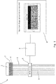
- FIG. 1 A schematic diagram of a wiring test device (1) according to an embodiment is shown in Figure 1 .
- the test device 1 is shown connected to a partially assembled wire harness 9, which comprises a connector housing 2 and a plurality of wires 5.
- the wire harness 9 is shown as a kit type harness, with the proximal ends of the wires 5 connected to individual terminal pins 4 within the terminal array of the connector housing 3, and the distal ends of the wires 5 being free floating.
- the wire harness 9 is shown as a kit type harness, with the proximal ends of the wires 5 connected to individual terminal pins 4 within the terminal array of the connector housing 3, and the distal ends of the wires 5 being free floating.
- one or more of these wires 5 may be terminated with a plug or other connector.
- the connector housing 3 is connected into a corresponding socket provided on the transmitter 2.
- the socket comprises a plurality of female port terminals which receive the male terminal pins 4 of the connector housing 3 when the connector housing 3 is fitted into the socket. This thereby establishes an electrical connection between the port terminals of the transmitter 2 and the individual wires 5 connected each terminal pin 4.
- the transmitter 2 is able to apply radio frequency, RF, orthogonal signals with different frequencies to each port within its interface.
- the use of orthogonal signals mitigates the risk that the signals' inferences could cause incorrect identification on detection.
- the signals applied to each port in turn applies the signals to each terminal pin 4 received by each port, respectively.
- those wires 5 function as antenna for emitting the associated RF signal.
- terminal pins 4 which have not had wires 5 connected to do not emit, or emit at very low amplitude, their associated RF signal.
- the device 1 further comprises a RF detector 6 which, in use, is located adjacent to the wires 5 and comprises an aerial for receiving RF signals emitted by the wires 5.
- the RF detector outputs a composite RF signal comprising the sum of the different RF frequency signals emitted by the wires 5 that have been connected to terminals 4.
- the RF detector 6 is connected to a processor 7 which is used to process the received RF signals and display a time-frequency plot representing the detected RF signals on display 8. This representation can therefore be used to identify which signals are present, and consequently which terminal pins 4 have had wires 5 connected.
- the time-frequency plot is generated using a Fast Fourier Transform algorithm and is displayed on display 8 as a waterfall plot.
- the waterfall plot thereby shows how the frequency components of the received composite RF signal changes over time.
- new wires 5 are sequentially connected to terminal pins 4 of the connector housing 3. Progress during the assembly process is reflected by a corresponding change in the waterfall plot displayed on display 8. That is, as new wires 5 are connected, new spectrum bands will appear on the waterfall, thereby allowing a technician to verify that a newly connected wire 5 has been connected to the correct terminal pin 4. In instances where a wire 5 is connected to the wrong terminal pin 4, a different frequency band than the band that had been expected will appear. A technician, or AI processing, can therefore identify this deviation from the expected sequences in which spectrum bands should appear as a wiring error, allowing the mistake to be corrected immediately.
- the processor 7 may automate the detection of connection errors by performing image recognition on the representation of the composite RF signal. For example, the technician may be tasked with connecting the wires 5 in a predetermined sequence. During this process, the processor 7 may identify deviations from the predetermined sequence by analysing the sequence of introduced spectrum bands on waterfall plot and determining the detected connection sequence based on this. The processor 7 may therefore alert the technician if wiring errors are detected.
- the processor 7 may access a data store comprising specification data representing the topology of the wire harness 9 to be created. Based on this specification data, the processor 7 may generate an expected spectrum map for the desired wire harness 9. During the assembly process, the generated RF signal representation can thereby be compared to this expected spectrum map, to alert the technician to any erroneous connections.
- the processor 7 may further automate the detection of connection errors using an artificial intelligence, AI, algorithm.
- AI artificial intelligence
- the AI algorithm may be exposed during a learning phase to the patterns of detected signals during test assembly operations.
- the test assembly operations may be categorised into those which result in wire harnesses being correctly connected and those which result in harnesses with defects. Based on this leaning phase, the AI algorithm may therefore identify a wider variety of connection mistakes during ongoing assembly operations based on the detected spectra over time.
- wire harness faults may be detected and rectified during the assembly process, providing for early fault detection. Furthermore, testing can be performed without having to physically connect both ends of the wires in the harness to a testing apparatus.
- the processor is shown as a unit physically connected to the detector, it will be understood that processing operations may be at least partially performed remotely. Equally, the processor may be connected to a server for performance data monitoring of, for instance, a technician's accuracy.
Landscapes
- Physics & Mathematics (AREA)
- General Physics & Mathematics (AREA)
- Testing Of Short-Circuits, Discontinuities, Leakage, Or Incorrect Line Connections (AREA)
Abstract
Description
- The present disclosure relates to a wire harness testing device and a method of verifying connections when assembling a wire harness. In particular, the present disclosure concerns a test device for verifying connections as the wire harness is assembled, and a method of using the same. The present disclosure is particularly suited to the assembly of wire harnesses for the automotive and aviation sectors.
- Wire harnesses (also known as cable harnesses, and wiring assemblies or looms) are used to connect electrical components within automobiles and aeroplanes, as well as other vehicles, and construction machinery. By binding a large number of wires together in a bundle, wiring can thereby be installed into a vehicle more quickly and reliably. However, in spite of increasing automation, wire harnesses are still generally assembled by hand. As such, wire harnesses are often one of the most expensive parts of a vehicle.
- Wire harnesses are typically assembled on an assembly board, which comprises a circuit diagram specific to the particular wire harness design. A technician will then match up wires and mini-bundles of wires to the circuit diagram on the assembly board surface. Once all the wires have been assembled on the board, the main bundle of wires will then be secured together using cable ties or tape, and will then be removed for testing. However, because of this, faulty electrical connections will often only be detected once the wire harness has been fully assembled, taped together, and removed from the assembly board.
- A particular problem occurs when a larger wire harness includes one or more sub-components of smaller wire harnesses. That is, each sub-component may comprise a small wire harness having a bundle of wires connected to one or more dedicated connectors, with each sub-component being preassembled before it is connected to the main assembly board to become part of the main wire-harness. In some instances, these sub-components are assembled as so-called "kits" in which the associated wire-harness is terminated with a connector only at one end. Consequently, the distal ends of the wires are unterminated and left floating, with these unterminated ends remaining unconnected until much later in the assembly processes when the sub-component is wired into the main wire harness. In such a scenario, conventionally, it is not possible to perform early stage testing to verify that the correct wires have been connected to the correct terminals of the connector. This is because it would be economically unviable to manually connect each unterminated wire to a test rig for testing. As such, current assessment of the correctness of the wiring within a sub-component or kit is based solely on visual inspection. Faults are therefore often not identified until the main wire harness has been fully assembled. At this late stage, correcting the fault would require considerable manual labour to unbind the cable bundle, and then locate and repair the wiring.
- The present disclosure seeks to address the above issues.
- According to a first aspect, there is provided a device for verifying wiring connections during the assembly of a wire harness, the wire harness comprising a connector having an array of terminals and a plurality wires connected to individual ones of the terminals, the device comprising: a transmitter for applying different signals to different terminals for emitting a corresponding electromagnetic signal from a wire connected to that terminal, each electromagnetic signal having an associated identifying characteristic; a detector for receiving electromagnetic signals emitted from wires connected to terminals; and a processor for generating an output for identifying the received electromagnetic signals based on their detected identifying characteristics.
- In this way, the individual wires serve as antenna for the respective terminals to which they are connected. Consequently, the detector, which may be provided as an aerial for receiving the electromagnetic waves, is able to detect signals from terminals which have had wires connected, whilst signals applied to unconnected terminals are not received. As each terminal has a different signal, it is therefore possible to identify which terminals have been wired and which haven't based on the identifying characteristics of the signals that are detected. Importantly, by using electromagnetic waves, testing may be conducted without having to electrically connect both ends of the wires to a testing apparatus. That is, the detector merely needs to be sufficiently close to the wires to receive the electromagnetic emissions, and does not require a physical connection. At the same time, the signals applied by the transmitter may be low power, and in embodiments are ultra-low power. Therefore, the transmitter can remain active as a technician connects new wires into the connector housing during the wire harness assembly process. A technician may thereby identify when a wire has been connected to the wrong terminal much earlier in the assembly process, and hence avoid the time and cost of having to undertake reworks after the wire harness has been fully assembled. It will be understood that the transmitter may be implemented as a Software-defined-radio (SDR) transmitter and the detector may be implemented as an SDR receiver.
- In embodiments, the identifying characteristic is frequency. As such, the transmitter may apply a plurality signals at different frequencies and the output may be based on the frequency spectrum of the detected signals. In embodiments, the plurality of signals are sine signals with orthogonal frequency (no harmonics). Such, sine signals may be keyed with a predefined frequency for delivering a larger variety of received waterfalls.
- In embodiments, the electromagnetic signals are radio frequency signals. This thereby allows for the generation and detection of the signals using relatively simple transmitter and detector apparatus, for example using SDR equipment.
- In embodiments, the processor comprises a display for displaying the output as a graphical representation of the identified signals. In this way, the processor may be provided as a computer workstation, with the display providing a technician with a graphical feedback of the wiring connections that have been made.
- In embodiments, the processor applies a Fast Fourier transform (FFT) for generating a time-frequency graphical representation of the identified signals. The change of FFT in time may be displayed on a Waterfall plot, and an artificial intelligence (AI) neural network may be used to interpret the received spectrum.
- In embodiments, the time-frequency graphical representation of the identified signals comprises a waterfall plot. In this way, the wiring of new wires to terminals can be easily identified as changes in the waterfall with the addition of new spectrum bands. Consequently, a technician assembling the wire harness can easily identify incorrect wiring operations. In embodiments, information or suggestions on connection status may also be provided by AI processing.
- In embodiments, the processor outputs which terminals have had wires connected based on changes in the time-frequency graphical representation. In this way, image recognition processing techniques may be applied to the graphical representation so as to identify which terminals have been connected.
- In embodiments, the processor further comprises logic for determining a wire has been connected to an incorrect terminal based on the detection of an electromagnetic signal with an identifying characteristic different to an expected identifying characteristic. In this way, the processor may be provided with specification data for the wire harness indicating which terminals should be connected, and may also indicate in which order connections should be made. Based on this, it is then possible to derive which signals, and in some embodiments the sequence of signals, that would be expected when the wire harness was being wired correctly. As such, deviations from these expected signals during the assembly process can be used to indicate when a terminal has been incorrectly wired.
- In embodiments, the transmitter may comprise an interface having a plurality of ports individually connectable to individual terminals for applying the different signals thereto.
- In embodiments, the plurality of ports comprises a port for each terminal within the array of terminals.
- In embodiments, the interface is provided as a counterpart connector for connection to the connector of the wire harness. In this way, the interface may be provided as a counterpart male or female connector corresponding to the male or female connector provided on the wire harness. As such, the wire harness connector can be attached to the transmitter by mating the connectors together, which thereby establishes the electrical connection between the interface and the terminals pins.
- According to a second aspect, there is provided a method for verifying connections when assembling a wire harness comprising the steps of: connecting a connector to a transmitter, the connector having an array of terminals; connecting a plurality of wires to individual ones of the terminals; applying, by the transmitter, different signals to different terminals for emitting a corresponding electromagnetic signal from a wire connected to that terminal, each electromagnetic signal having an associated identifying characteristic; receiving, by a detector, electromagnetic signals emitted from wires connected to terminals; and generating an output, by a processor, for identifying the received electromagnetic signals based on their detected identifying characteristics.
- In this way, a technician assembling a wire harness can be alerted to instances where a wire has been connected to the wrong terminal during the assembly process. This mitigates the risk of having to undertake reworks to correct errors once the wire harness has been fully assembled. Furthermore, testing can be undertaken without needing to connect both ends of a wire to a testing apparatus, thereby allowing the testing of wire harnesses having floating ends.
- In embodiments, the method further comprises applying, by the processor, a Fast Fourier transform to generate a time-frequency graphical representation of the identified signals; and displaying the time-frequency graphical representation on a display as the output. For example, in embodiments, SDR may be used to receive and initially process the signals, after which FFT is applied and then the results are displayed on a Waterfall plot.
- In embodiments, the method further comprises outputting, by the processor, which terminals have had wires connected based on changes in the time-frequency graphical representation.
- In embodiments, the step of connecting the plurality of wires comprises connecting the wires to their associated terminals in a sequence, and the method further comprises identifying, by the processor, when a wire has been connected to an incorrect terminal based on the detected sequence of electromagnetic signals having different identifying characteristics than an expected sequence of electromagnetic signals.
- Illustrative embodiments will now be described with reference to the accompanying drawing in which:
-
Figure 1 shows a schematic view of a wiring test device according to an embodiment. - A schematic diagram of a wiring test device (1) according to an embodiment is shown in
Figure 1 . Thetest device 1 is shown connected to a partially assembledwire harness 9, which comprises aconnector housing 2 and a plurality ofwires 5. In this illustrative example, thewire harness 9 is shown as a kit type harness, with the proximal ends of thewires 5 connected to individualterminal pins 4 within the terminal array of the connector housing 3, and the distal ends of thewires 5 being free floating. However, it will be understood that one or more of thesewires 5 may be terminated with a plug or other connector. - The connector housing 3 is connected into a corresponding socket provided on the
transmitter 2. The socket comprises a plurality of female port terminals which receive the male terminal pins 4 of the connector housing 3 when the connector housing 3 is fitted into the socket. This thereby establishes an electrical connection between the port terminals of thetransmitter 2 and theindividual wires 5 connected eachterminal pin 4. - In use, the
transmitter 2 is able to apply radio frequency, RF, orthogonal signals with different frequencies to each port within its interface. The use of orthogonal signals mitigates the risk that the signals' inferences could cause incorrect identification on detection. The signals applied to each port in turn applies the signals to eachterminal pin 4 received by each port, respectively. For theterminal pins 4 to whichwires 5 have been connected, thosewires 5 function as antenna for emitting the associated RF signal. Conversely,terminal pins 4 which have not hadwires 5 connected to do not emit, or emit at very low amplitude, their associated RF signal. - The
device 1 further comprises aRF detector 6 which, in use, is located adjacent to thewires 5 and comprises an aerial for receiving RF signals emitted by thewires 5. As such, the RF detector outputs a composite RF signal comprising the sum of the different RF frequency signals emitted by thewires 5 that have been connected toterminals 4. - The
RF detector 6 is connected to aprocessor 7 which is used to process the received RF signals and display a time-frequency plot representing the detected RF signals ondisplay 8. This representation can therefore be used to identify which signals are present, and consequently which terminal pins 4 have hadwires 5 connected. - In this embodiment, the time-frequency plot is generated using a Fast Fourier Transform algorithm and is displayed on
display 8 as a waterfall plot. The waterfall plot thereby shows how the frequency components of the received composite RF signal changes over time. - During the assembly of a
wire harness 9,new wires 5 are sequentially connected toterminal pins 4 of the connector housing 3. Progress during the assembly process is reflected by a corresponding change in the waterfall plot displayed ondisplay 8. That is, asnew wires 5 are connected, new spectrum bands will appear on the waterfall, thereby allowing a technician to verify that a newly connectedwire 5 has been connected to the correctterminal pin 4. In instances where awire 5 is connected to the wrongterminal pin 4, a different frequency band than the band that had been expected will appear. A technician, or AI processing, can therefore identify this deviation from the expected sequences in which spectrum bands should appear as a wiring error, allowing the mistake to be corrected immediately. - In other embodiments, the
processor 7 may automate the detection of connection errors by performing image recognition on the representation of the composite RF signal. For example, the technician may be tasked with connecting thewires 5 in a predetermined sequence. During this process, theprocessor 7 may identify deviations from the predetermined sequence by analysing the sequence of introduced spectrum bands on waterfall plot and determining the detected connection sequence based on this. Theprocessor 7 may therefore alert the technician if wiring errors are detected. - In other embodiments, the
processor 7 may access a data store comprising specification data representing the topology of thewire harness 9 to be created. Based on this specification data, theprocessor 7 may generate an expected spectrum map for the desiredwire harness 9. During the assembly process, the generated RF signal representation can thereby be compared to this expected spectrum map, to alert the technician to any erroneous connections. - In other embodiments, the
processor 7 may further automate the detection of connection errors using an artificial intelligence, AI, algorithm. In this case, the AI algorithm may be exposed during a learning phase to the patterns of detected signals during test assembly operations. The test assembly operations may be categorised into those which result in wire harnesses being correctly connected and those which result in harnesses with defects. Based on this leaning phase, the AI algorithm may therefore identify a wider variety of connection mistakes during ongoing assembly operations based on the detected spectra over time. - Accordingly, with embodiments, wire harness faults may be detected and rectified during the assembly process, providing for early fault detection. Furthermore, testing can be performed without having to physically connect both ends of the wires in the harness to a testing apparatus.
- It will be understood that the embodiment illustrated above show applications only for the purposes of illustration. In practice the disclosure may be applied to many different configurations, the detail of which being straightforward for those skilled in the art to implement.
- For example, although in the above illustrative embodiments, the processor is shown as a unit physically connected to the detector, it will be understood that processing operations may be at least partially performed remotely. Equally, the processor may be connected to a server for performance data monitoring of, for instance, a technician's accuracy.
Claims (15)
- A device (1) for verifying wiring connections during the assembly of a wire harness (9), the wire harness (9) comprising a connector (3) having an array of terminals (4) and a plurality wires (5) connected to individual ones of the terminals (4), the device comprising:a transmitter (2) for applying different signals to different terminals (4) for emitting a corresponding electromagnetic signal from a wire (5) connected to that terminal (4), each electromagnetic signal having an associated identifying characteristic;a detector (6) for receiving electromagnetic signals emitted from wires (5) connected to terminals (4); anda processor (7) for generating an output for identifying the received electromagnetic signals based on their detected identifying characteristics.
- A device according to claim 1, wherein the identifying characteristic is frequency.
- A device according to claim 1 or 2, wherein the electromagnetic signals are radio frequency signals.
- A device according to any preceding claim, wherein the processor (7) comprises a display (8) for displaying the output as a graphical representation of the identified signals.
- A device according to claim 4, wherein the processor (7) applies a Fast Fourier transform for generating a time-frequency graphical representation of the identified signals.
- A device according to claim 5, wherein the time-frequency graphical representation of the identified signals comprises a waterfall plot.
- A device according to claim 5 or 6, wherein the processor (7) outputs which terminals (4) have had wires (5) connected based on changes in the time-frequency graphical representation.
- A device according to any preceding claim, wherein the processor (7) further comprises logic for determining a wire (5) has been connected to an incorrect terminal (4) based on the detection of an electromagnetic signal with an identifying characteristic different to an expected identifying characteristic.
- A device according to any preceding claim, wherein the transmitter (2) comprises an interface having a plurality of ports individually connectable to individual terminals (4) for applying the different signals thereto.
- A device according to claim 9, wherein the plurality of ports comprises a port for each terminal (4) within the array of terminals (4).
- A device according to claim 9 or 10, wherein the interface is provided as a counterpart connector for connection to the connector (3) of the wire harness (9).
- A method for verifying connections when assembling a wire harness comprising the steps of:connecting a connector (3) to a transmitter (2), the connector (3) having an array of terminals (4);connecting a plurality of wires (5) to individual ones of the terminals (4);applying, by the transmitter (2), different signals to different terminals (4) for emitting a corresponding electromagnetic signal from a wire (5) connected to that terminal (4), each electromagnetic signal having an associated identifying characteristic;receiving, by a detector (6), electromagnetic signals emitted from wires (5) connected to terminals (4); andgenerating an output, by a processor (7), for identifying the received electromagnetic signals based on their detected identifying characteristics.
- A method according to claim 12, further comprising applying, by the processor (7), a Fast Fourier transform to generate a time-frequency graphical representation of the identified signals; and
displaying the time-frequency graphical representation on a display (8) as the output. - A method according to claim 13, further comprising outputting, by the processor (7), which terminals (4) have had wires (5) connected based on changes in the time-frequency graphical representation.
- A method according to any one of claims 12 to 14, wherein the step of connecting the plurality of wires (5) comprises connecting the wires (5) to their associated terminals (4) in a sequence, and
the method further comprises identifying, by the processor (7), when a wire has been connected to an incorrect terminal(4) based on the detected sequence of electromagnetic signals having different identifying characteristics than an expected sequence of electromagnetic signals.
Priority Applications (3)
| Application Number | Priority Date | Filing Date | Title |
|---|---|---|---|
| EP20159896.8A EP3872513B8 (en) | 2020-02-27 | 2020-02-27 | Wire harness test device and method for verifying connections when assembling a wire harness |
| US17/171,923 US11543464B2 (en) | 2020-02-27 | 2021-02-09 | Wire harness test device and method for verifying connections when assembling a wire harness |
| CN202110216830.8A CN113311366B (en) | 2020-02-27 | 2021-02-26 | Wire harness testing apparatus and method for verifying connections when assembling a wire harness |
Applications Claiming Priority (1)
| Application Number | Priority Date | Filing Date | Title |
|---|---|---|---|
| EP20159896.8A EP3872513B8 (en) | 2020-02-27 | 2020-02-27 | Wire harness test device and method for verifying connections when assembling a wire harness |
Publications (3)
| Publication Number | Publication Date |
|---|---|
| EP3872513A1 true EP3872513A1 (en) | 2021-09-01 |
| EP3872513B1 EP3872513B1 (en) | 2024-03-27 |
| EP3872513B8 EP3872513B8 (en) | 2024-05-01 |
Family
ID=69742831
Family Applications (1)
| Application Number | Title | Priority Date | Filing Date |
|---|---|---|---|
| EP20159896.8A Active EP3872513B8 (en) | 2020-02-27 | 2020-02-27 | Wire harness test device and method for verifying connections when assembling a wire harness |
Country Status (3)
| Country | Link |
|---|---|
| US (1) | US11543464B2 (en) |
| EP (1) | EP3872513B8 (en) |
| CN (1) | CN113311366B (en) |
Families Citing this family (5)
| Publication number | Priority date | Publication date | Assignee | Title |
|---|---|---|---|---|
| EP3871928B1 (en) | 2020-02-27 | 2025-03-26 | Aptiv Technologies AG | Component connection verification device and method |
| EP3872512B1 (en) | 2020-02-27 | 2026-02-11 | Aptiv Technologies AG | Wiring assembly board and method for verifying connections when assembling a wire harness |
| CN116256670B (en) * | 2022-12-30 | 2026-03-20 | 大连尚佳新能源科技有限公司 | A multi-channel line inspection device and method |
| CN117250561B (en) * | 2023-11-09 | 2024-03-12 | 优联电气系统(苏州)有限公司 | An electrical wire harness detection method and system based on big data |
| EP4624946A1 (en) * | 2024-03-29 | 2025-10-01 | Valeo Vision | A wire harness automated diagnosis system and method |
Citations (8)
| Publication number | Priority date | Publication date | Assignee | Title |
|---|---|---|---|---|
| US3681686A (en) * | 1970-07-27 | 1972-08-01 | Apc Ind Inc | Conductor identification via counting means at a remote position |
| US6282265B1 (en) * | 2000-03-07 | 2001-08-28 | Harris Corporation | Two-ended wireline pair identification system |
| US20020171434A1 (en) * | 2001-05-15 | 2002-11-21 | Stanford James G. | Method of performing a dielectric voltage-withstand test on a wire harness |
| US20060043976A1 (en) * | 2004-09-02 | 2006-03-02 | Francois Gervais | Wireless portable automated harness scanner system and method therefor |
| US20130049731A1 (en) * | 2011-08-22 | 2013-02-28 | Technical Services For Electronics, Inc. | Coax ribbonizing header |
| US20140292349A1 (en) * | 2013-03-31 | 2014-10-02 | Ziota Inc. | Electronic identification slave connector |
| US20180276321A1 (en) * | 2017-03-24 | 2018-09-27 | The Boeing Company | Method and apparatus for testing design of satellite wiring harness and signal processing units |
| WO2019187349A1 (en) * | 2018-03-27 | 2019-10-03 | 住友電気工業株式会社 | Connector system, connector and connection method |
Family Cites Families (62)
| Publication number | Priority date | Publication date | Assignee | Title |
|---|---|---|---|---|
| JPS4920191B1 (en) | 1970-10-28 | 1974-05-23 | ||
| US3891811A (en) * | 1973-08-16 | 1975-06-24 | Hewlett Packard Co | Wire pair identification system |
| US4506210A (en) * | 1982-02-18 | 1985-03-19 | The United States Of America As Represented By The Secretary Of The Army | Method for identifying cable conductors using two signals at different frequencies |
| US4959792A (en) * | 1986-01-24 | 1990-09-25 | Sullivan Thomas P | Harness integrity tester (hit) |
| US4937519A (en) * | 1988-08-16 | 1990-06-26 | Jupiter Toy Company | Apparatus and method for identifying conductors |
| DE69002828T2 (en) * | 1989-02-13 | 1994-01-20 | Radiodetection Ltd | METHOD FOR DETECTING ELECTRICAL LADDERS. |
| US4951385A (en) | 1989-05-16 | 1990-08-28 | Desanto Joseph J | Electrical harness assembly apparatus |
| US5361029A (en) * | 1990-06-18 | 1994-11-01 | The Charles Machine Works, Inc. | System for locating multiple concealed underground objects |
| US5280251A (en) * | 1991-11-07 | 1994-01-18 | Cami Research, Inc. | Continuity analysis system with graphic wiring display |
| US5420512A (en) * | 1991-11-21 | 1995-05-30 | Paladin Corporation | Electronic cable testing system |
| CA2113836C (en) * | 1992-05-20 | 2002-01-29 | Dongzhi Jin | Method and apparatus for identifying objects using compound signal and a detector employing an electrical static coupling technique |
| US5483169A (en) * | 1994-07-30 | 1996-01-09 | Mcdonnell Douglas Corporation | RF imaging of low observable coatings using a wire-over-ground-plane transmission line |
| US5557651A (en) * | 1995-06-05 | 1996-09-17 | Tempo Research Corporation | Signal generator for tracing multiple transmission lines |
| JP3640150B2 (en) | 1999-10-29 | 2005-04-20 | 住友電装株式会社 | Layout examination method of continuity test unit, pseudo unit and layout examination table |
| AU2001246540A1 (en) | 2000-04-18 | 2001-10-30 | Wee Electrotest Engineering Gmbh | Method and device for testing cable trees |
| DE10019860C1 (en) | 2000-04-18 | 2001-10-31 | Wee Electrotest Engineering Gm | Apparatus for testing cable structures using a programmable control computer |
| US6448778B1 (en) * | 2001-01-29 | 2002-09-10 | Honda Of America Mfg., Inc. | Automated verification of proper connectivity of components to a wiring harness during assembly of article of manufacture |
| US6803770B2 (en) * | 2002-10-08 | 2004-10-12 | The United States Of America As Represented By The Secretary Of The Navy | Wireless multiconductor cable test system and method |
| DE10308403B4 (en) | 2003-02-27 | 2007-10-31 | Kannenberg, Dirk-Uwe, Dipl.-Ing. | Method and device for monitoring the assembly of a component |
| JP4121420B2 (en) * | 2003-06-02 | 2008-07-23 | 住友電装株式会社 | Harness checker and harness check method |
| US7068041B2 (en) * | 2003-11-26 | 2006-06-27 | General Electric Company | Method and system for multi-frequency inductive ratio measurement |
| US8552709B2 (en) * | 2004-02-18 | 2013-10-08 | Tasco Inc. | Systems and methods for locating a circuit |
| CN101473210A (en) * | 2004-07-27 | 2009-07-01 | 纳特维斯公司 | System and method for collecting, storing, processing, transmitting and presenting very low amplitude signals |
| JP4920191B2 (en) | 2005-02-10 | 2012-04-18 | 日産自動車株式会社 | Connector fitting state confirmation device and method |
| US20070030014A1 (en) * | 2005-08-03 | 2007-02-08 | Harshang Pandya | Multi-jack cable adapter for multi-cable testing and alien cross-talk cable testing |
| TWI320485B (en) * | 2007-03-08 | 2010-02-11 | Test Research Inc | Open-circuit testing system and method |
| JP2008226506A (en) | 2007-03-09 | 2008-09-25 | Kanto Auto Works Ltd | Connection state judging device of connector |
| DE102007024476A1 (en) | 2007-05-25 | 2008-11-27 | Dirk Selbach | Wiring harness manufacturing system |
| DE102007063283A1 (en) | 2007-12-27 | 2009-07-02 | Robert Bosch Gmbh | Test device for a plug connection |
| US8378705B2 (en) | 2008-02-29 | 2013-02-19 | Nhk Spring Co., Ltd. | Wiring substrate and probe card |
| US8076923B2 (en) * | 2008-05-23 | 2011-12-13 | Consolidated Edison Company Of New York, Inc. | Dead-line phase identification system and method thereof |
| US9342716B2 (en) * | 2010-02-04 | 2016-05-17 | Carefusion 303, Inc. | Software-defined multi-mode RFID read devices |
| US8560262B2 (en) * | 2010-06-18 | 2013-10-15 | Apple Inc. | Methods for manufacturing devices with flex circuits and radio-frequency cables |
| KR20120101873A (en) * | 2011-03-07 | 2012-09-17 | 삼성전자주식회사 | Prediction apparatus and method for electromagnetic radiated emission of cable |
| US20130018624A1 (en) | 2011-07-15 | 2013-01-17 | Anuj Bhatnagar | System For Manufacturing Cables |
| EP2896010A4 (en) | 2012-09-12 | 2016-04-27 | Iex Group Inc | Transmission latency leveling apparatuses, methods and systems |
| US9136682B2 (en) * | 2013-05-03 | 2015-09-15 | Lenovo Enterprise Solutions (Singapore) Pte. Ltd. | Cable tracing in a datacenter |
| CN203376424U (en) * | 2013-05-22 | 2014-01-01 | 宁德时代新能源科技有限公司 | Wire harness detection apparatus |
| US9491557B2 (en) | 2013-10-07 | 2016-11-08 | Tyco Electronics Corporation | Connector mating assurance system and method |
| US9818179B2 (en) * | 2013-12-05 | 2017-11-14 | Bombardier Transportation Gmbh | Method for manufacturing a wire harness |
| ES2751372T3 (en) | 2014-02-24 | 2020-03-31 | Airbus Defence And Space Sa | System for conducting electrical tests on electrical harnesses |
| WO2016090342A2 (en) | 2014-12-05 | 2016-06-09 | Stages Pcs, Llc | Active noise control and customized audio system |
| US20160356836A1 (en) * | 2015-06-02 | 2016-12-08 | John M Horan | Apparatus and method for data transmission and testing |
| US9939483B2 (en) | 2015-10-07 | 2018-04-10 | Te Connectivity Corporation | Connector mating assurance system and method |
| KR101735508B1 (en) * | 2015-10-12 | 2017-05-15 | (주)가온테크 | Wiring tester and test method of Industrial and automotive wire harness |
| US9813810B1 (en) | 2016-01-05 | 2017-11-07 | Google Inc. | Multi-microphone neural network for sound recognition |
| US10492008B2 (en) | 2016-04-06 | 2019-11-26 | Starkey Laboratories, Inc. | Hearing device with neural network-based microphone signal processing |
| DE102016213536A1 (en) | 2016-07-25 | 2018-01-25 | Bayerische Motoren Werke Aktiengesellschaft | Method for monitoring the assembly of connectors |
| CN106855600A (en) * | 2016-12-14 | 2017-06-16 | 中航通飞研究院有限公司 | A kind of aircraft wire harness conducting wireless detection device based on RFID |
| US10782348B2 (en) * | 2017-03-10 | 2020-09-22 | Keithley Instruments, Llc | Automatic device detection and connection verification |
| CN107122738B (en) * | 2017-04-26 | 2020-05-22 | 成都蓝色起源科技有限公司 | Radio signal identification method based on deep learning model and implementation system thereof |
| DE102017213147A1 (en) | 2017-07-31 | 2019-01-31 | Bayerische Motoren Werke Aktiengesellschaft | Method for checking connectors |
| DE102017122223A1 (en) | 2017-09-26 | 2019-03-28 | TSK Prüfsysteme GmbH | Test module for a test table and method for forming a test table |
| US10663532B2 (en) * | 2017-10-24 | 2020-05-26 | Hamilton Sundstrand Corporation | Method of testing cable shield performance |
| EP3522311B1 (en) * | 2018-02-01 | 2021-05-19 | Aptiv Technologies Limited | Assisted assembly method and system |
| CN108764013A (en) * | 2018-03-28 | 2018-11-06 | 中国科学院软件研究所 | A kind of automatic Communication Signals Recognition based on end-to-end convolutional neural networks |
| US11022638B2 (en) * | 2018-04-04 | 2021-06-01 | Fluke Corporation | Testing shield continuity of a cable or cabling installation using common mode insertion loss |
| CN110597477B (en) | 2018-06-12 | 2024-05-28 | 哈曼国际工业有限公司 | Directional Sound Modification |
| US10996286B2 (en) * | 2018-11-29 | 2021-05-04 | The Boeing Company | Test system and method for a wiring harness |
| CN109470974A (en) | 2018-12-10 | 2019-03-15 | 沈阳兴华航空电器有限责任公司 | A cable testing system and method based on wireless technology |
| EP3871928B1 (en) | 2020-02-27 | 2025-03-26 | Aptiv Technologies AG | Component connection verification device and method |
| EP3872512B1 (en) | 2020-02-27 | 2026-02-11 | Aptiv Technologies AG | Wiring assembly board and method for verifying connections when assembling a wire harness |
-
2020
- 2020-02-27 EP EP20159896.8A patent/EP3872513B8/en active Active
-
2021
- 2021-02-09 US US17/171,923 patent/US11543464B2/en active Active
- 2021-02-26 CN CN202110216830.8A patent/CN113311366B/en active Active
Patent Citations (8)
| Publication number | Priority date | Publication date | Assignee | Title |
|---|---|---|---|---|
| US3681686A (en) * | 1970-07-27 | 1972-08-01 | Apc Ind Inc | Conductor identification via counting means at a remote position |
| US6282265B1 (en) * | 2000-03-07 | 2001-08-28 | Harris Corporation | Two-ended wireline pair identification system |
| US20020171434A1 (en) * | 2001-05-15 | 2002-11-21 | Stanford James G. | Method of performing a dielectric voltage-withstand test on a wire harness |
| US20060043976A1 (en) * | 2004-09-02 | 2006-03-02 | Francois Gervais | Wireless portable automated harness scanner system and method therefor |
| US20130049731A1 (en) * | 2011-08-22 | 2013-02-28 | Technical Services For Electronics, Inc. | Coax ribbonizing header |
| US20140292349A1 (en) * | 2013-03-31 | 2014-10-02 | Ziota Inc. | Electronic identification slave connector |
| US20180276321A1 (en) * | 2017-03-24 | 2018-09-27 | The Boeing Company | Method and apparatus for testing design of satellite wiring harness and signal processing units |
| WO2019187349A1 (en) * | 2018-03-27 | 2019-10-03 | 住友電気工業株式会社 | Connector system, connector and connection method |
Non-Patent Citations (1)
| Title |
|---|
| KIRK BENJAMIN H ET AL: "Cognitive software defined radar: A reactive approach to RFI avoidance", 2018 IEEE RADAR CONFERENCE (RADARCONF18), IEEE, 23 April 2018 (2018-04-23), pages 630 - 635, XP033356279, DOI: 10.1109/RADAR.2018.8378632 * |
Also Published As
| Publication number | Publication date |
|---|---|
| US11543464B2 (en) | 2023-01-03 |
| EP3872513B1 (en) | 2024-03-27 |
| US20210270912A1 (en) | 2021-09-02 |
| EP3872513B8 (en) | 2024-05-01 |
| CN113311366A (en) | 2021-08-27 |
| CN113311366B (en) | 2024-08-30 |
Similar Documents
| Publication | Publication Date | Title |
|---|---|---|
| US11543464B2 (en) | Wire harness test device and method for verifying connections when assembling a wire harness | |
| US12174219B2 (en) | Universal mate-in cable interface system | |
| US8547108B2 (en) | Universal mate-in cable interface system | |
| EP2531867B1 (en) | Cable test method | |
| US9810732B2 (en) | Universal mate-in cable interface system | |
| US20180017608A1 (en) | Electrical in-system process control tester | |
| CN117250561A (en) | An electrical wire harness detection method and system based on big data | |
| US9921263B2 (en) | Electronic identification slave connector | |
| US8823389B2 (en) | Method for identifying EMI sources in an electrical system | |
| KR20120124378A (en) | The Electromagnetic Method And Apparatus for Inspection of the Cable Harness | |
| CN107271854B (en) | Dual-redundancy equipotential cable network mixed wire testing device and testing method | |
| US10591528B2 (en) | System and method for using a connector at the end of a cable as a cable locating tone sensor | |
| KR101663219B1 (en) | Apparatus and Method for checking electricity electronic circuit using interface signal simulation between in components | |
| JP3659007B2 (en) | Test jig inspection method | |
| CN112485729A (en) | Method for detecting connection state of electric connector | |
| CN222719696U (en) | Wire harness multipath CAN wire conduction loop test circuit device | |
| CN110542825A (en) | testing equipment and testing method for wiring integrity of product | |
| US20250130291A1 (en) | Binary scan system for leakage detection in wire harnesses | |
| US20250306569A1 (en) | Method for error-minimized stack contacting | |
| CN119846309A (en) | Vehicle three-phase line shielding layer detection system and detection method | |
| CN120303569A (en) | Method and associated apparatus for detecting electrical faults in a cable network of a wiring harness | |
| US20210364576A1 (en) | Use of Standing Wave Ratio Measurements for Interconnect Testing | |
| RU2694170C1 (en) | Method of control of extended multicore cables | |
| CN118550738A (en) | Fault detection system and fault detection method for storage recording device | |
| JP2022120857A (en) | Abnormality inspection device and abnormality inspection method |
Legal Events
| Date | Code | Title | Description |
|---|---|---|---|
| PUAI | Public reference made under article 153(3) epc to a published international application that has entered the european phase |
Free format text: ORIGINAL CODE: 0009012 |
|
| STAA | Information on the status of an ep patent application or granted ep patent |
Free format text: STATUS: THE APPLICATION HAS BEEN PUBLISHED |
|
| AK | Designated contracting states |
Kind code of ref document: A1 Designated state(s): AL AT BE BG CH CY CZ DE DK EE ES FI FR GB GR HR HU IE IS IT LI LT LU LV MC MK MT NL NO PL PT RO RS SE SI SK SM TR |
|
| STAA | Information on the status of an ep patent application or granted ep patent |
Free format text: STATUS: REQUEST FOR EXAMINATION WAS MADE |
|
| 17P | Request for examination filed |
Effective date: 20220301 |
|
| RBV | Designated contracting states (corrected) |
Designated state(s): AL AT BE BG CH CY CZ DE DK EE ES FI FR GB GR HR HU IE IS IT LI LT LU LV MC MK MT NL NO PL PT RO RS SE SI SK SM TR |
|
| RAP3 | Party data changed (applicant data changed or rights of an application transferred) |
Owner name: APTIV TECHNOLOGIES LIMITED |
|
| GRAP | Despatch of communication of intention to grant a patent |
Free format text: ORIGINAL CODE: EPIDOSNIGR1 |
|
| STAA | Information on the status of an ep patent application or granted ep patent |
Free format text: STATUS: GRANT OF PATENT IS INTENDED |
|
| RIC1 | Information provided on ipc code assigned before grant |
Ipc: G01R 31/60 20200101AFI20230925BHEP |
|
| INTG | Intention to grant announced |
Effective date: 20231013 |
|
| GRAS | Grant fee paid |
Free format text: ORIGINAL CODE: EPIDOSNIGR3 |
|
| GRAA | (expected) grant |
Free format text: ORIGINAL CODE: 0009210 |
|
| STAA | Information on the status of an ep patent application or granted ep patent |
Free format text: STATUS: THE PATENT HAS BEEN GRANTED |
|
| AK | Designated contracting states |
Kind code of ref document: B1 Designated state(s): AL AT BE BG CH CY CZ DE DK EE ES FI FR GB GR HR HU IE IS IT LI LT LU LV MC MK MT NL NO PL PT RO RS SE SI SK SM TR |
|
| REG | Reference to a national code |
Ref country code: GB Ref legal event code: FG4D |
|
| REG | Reference to a national code |
Ref country code: CH Ref legal event code: EP |
|
| P01 | Opt-out of the competence of the unified patent court (upc) registered |
Effective date: 20240304 |
|
| REG | Reference to a national code |
Ref country code: DE Ref legal event code: R081 Ref document number: 602020027763 Country of ref document: DE Owner name: APTIV TECHNOLOGIES AG, CH Free format text: FORMER OWNER: APTIV TECHNOLOGIES LIMITED, ST. MICHAEL, BB |
|
| REG | Reference to a national code |
Ref country code: DE Ref legal event code: R096 Ref document number: 602020027763 Country of ref document: DE |
|
| REG | Reference to a national code |
Ref country code: CH Ref legal event code: PK Free format text: BERICHTIGUNG B8 |
|
| RAP2 | Party data changed (patent owner data changed or rights of a patent transferred) |
Owner name: APTIV TECHNOLOGIES AG |
|
| REG | Reference to a national code |
Ref country code: IE Ref legal event code: FG4D |
|
| REG | Reference to a national code |
Ref country code: CH Ref legal event code: PK Free format text: DIE PUBLIKATION VOM 27.03.2024 WURDE AM 24.04.2024 IRRTUEMLICHERWEISE ERNEUT PUBLIZIERT. LA PUBLICATION DU 27.03.2024 A ETE REPUBLIEE PAR ERREUR LE 24.04.2024. LA PUBBLICAZIONE DEL 27.03.2024 E STATA ERRONEAMENTE RIPUBBLICATA IL 24.04.2024. |
|
| PG25 | Lapsed in a contracting state [announced via postgrant information from national office to epo] |
Ref country code: LT Free format text: LAPSE BECAUSE OF FAILURE TO SUBMIT A TRANSLATION OF THE DESCRIPTION OR TO PAY THE FEE WITHIN THE PRESCRIBED TIME-LIMIT Effective date: 20240327 |
|
| REG | Reference to a national code |
Ref country code: LT Ref legal event code: MG9D |
|
| PG25 | Lapsed in a contracting state [announced via postgrant information from national office to epo] |
Ref country code: GR Free format text: LAPSE BECAUSE OF FAILURE TO SUBMIT A TRANSLATION OF THE DESCRIPTION OR TO PAY THE FEE WITHIN THE PRESCRIBED TIME-LIMIT Effective date: 20240628 |
|
| PG25 | Lapsed in a contracting state [announced via postgrant information from national office to epo] |
Ref country code: HR Free format text: LAPSE BECAUSE OF FAILURE TO SUBMIT A TRANSLATION OF THE DESCRIPTION OR TO PAY THE FEE WITHIN THE PRESCRIBED TIME-LIMIT Effective date: 20240327 Ref country code: RS Free format text: LAPSE BECAUSE OF FAILURE TO SUBMIT A TRANSLATION OF THE DESCRIPTION OR TO PAY THE FEE WITHIN THE PRESCRIBED TIME-LIMIT Effective date: 20240627 |
|
| PG25 | Lapsed in a contracting state [announced via postgrant information from national office to epo] |
Ref country code: RS Free format text: LAPSE BECAUSE OF FAILURE TO SUBMIT A TRANSLATION OF THE DESCRIPTION OR TO PAY THE FEE WITHIN THE PRESCRIBED TIME-LIMIT Effective date: 20240627 Ref country code: NO Free format text: LAPSE BECAUSE OF FAILURE TO SUBMIT A TRANSLATION OF THE DESCRIPTION OR TO PAY THE FEE WITHIN THE PRESCRIBED TIME-LIMIT Effective date: 20240627 Ref country code: LT Free format text: LAPSE BECAUSE OF FAILURE TO SUBMIT A TRANSLATION OF THE DESCRIPTION OR TO PAY THE FEE WITHIN THE PRESCRIBED TIME-LIMIT Effective date: 20240327 Ref country code: HR Free format text: LAPSE BECAUSE OF FAILURE TO SUBMIT A TRANSLATION OF THE DESCRIPTION OR TO PAY THE FEE WITHIN THE PRESCRIBED TIME-LIMIT Effective date: 20240327 Ref country code: GR Free format text: LAPSE BECAUSE OF FAILURE TO SUBMIT A TRANSLATION OF THE DESCRIPTION OR TO PAY THE FEE WITHIN THE PRESCRIBED TIME-LIMIT Effective date: 20240628 Ref country code: FI Free format text: LAPSE BECAUSE OF FAILURE TO SUBMIT A TRANSLATION OF THE DESCRIPTION OR TO PAY THE FEE WITHIN THE PRESCRIBED TIME-LIMIT Effective date: 20240327 Ref country code: BG Free format text: LAPSE BECAUSE OF FAILURE TO SUBMIT A TRANSLATION OF THE DESCRIPTION OR TO PAY THE FEE WITHIN THE PRESCRIBED TIME-LIMIT Effective date: 20240327 |
|
| REG | Reference to a national code |
Ref country code: NL Ref legal event code: MP Effective date: 20240327 |
|
| PG25 | Lapsed in a contracting state [announced via postgrant information from national office to epo] |
Ref country code: SE Free format text: LAPSE BECAUSE OF FAILURE TO SUBMIT A TRANSLATION OF THE DESCRIPTION OR TO PAY THE FEE WITHIN THE PRESCRIBED TIME-LIMIT Effective date: 20240327 Ref country code: LV Free format text: LAPSE BECAUSE OF FAILURE TO SUBMIT A TRANSLATION OF THE DESCRIPTION OR TO PAY THE FEE WITHIN THE PRESCRIBED TIME-LIMIT Effective date: 20240327 |
|
| PG25 | Lapsed in a contracting state [announced via postgrant information from national office to epo] |
Ref country code: NL Free format text: LAPSE BECAUSE OF FAILURE TO SUBMIT A TRANSLATION OF THE DESCRIPTION OR TO PAY THE FEE WITHIN THE PRESCRIBED TIME-LIMIT Effective date: 20240327 |
|
| REG | Reference to a national code |
Ref country code: AT Ref legal event code: MK05 Ref document number: 1670419 Country of ref document: AT Kind code of ref document: T Effective date: 20240327 |
|
| RAP4 | Party data changed (patent owner data changed or rights of a patent transferred) |
Owner name: APTIV TECHNOLOGIES AG |
|
| PG25 | Lapsed in a contracting state [announced via postgrant information from national office to epo] |
Ref country code: NL Free format text: LAPSE BECAUSE OF FAILURE TO SUBMIT A TRANSLATION OF THE DESCRIPTION OR TO PAY THE FEE WITHIN THE PRESCRIBED TIME-LIMIT Effective date: 20240327 |
|
| PG25 | Lapsed in a contracting state [announced via postgrant information from national office to epo] |
Ref country code: IS Free format text: LAPSE BECAUSE OF FAILURE TO SUBMIT A TRANSLATION OF THE DESCRIPTION OR TO PAY THE FEE WITHIN THE PRESCRIBED TIME-LIMIT Effective date: 20240727 |
|
| PG25 | Lapsed in a contracting state [announced via postgrant information from national office to epo] |
Ref country code: PT Free format text: LAPSE BECAUSE OF FAILURE TO SUBMIT A TRANSLATION OF THE DESCRIPTION OR TO PAY THE FEE WITHIN THE PRESCRIBED TIME-LIMIT Effective date: 20240729 Ref country code: SM Free format text: LAPSE BECAUSE OF FAILURE TO SUBMIT A TRANSLATION OF THE DESCRIPTION OR TO PAY THE FEE WITHIN THE PRESCRIBED TIME-LIMIT Effective date: 20240327 |
|
| PG25 | Lapsed in a contracting state [announced via postgrant information from national office to epo] |
Ref country code: ES Free format text: LAPSE BECAUSE OF FAILURE TO SUBMIT A TRANSLATION OF THE DESCRIPTION OR TO PAY THE FEE WITHIN THE PRESCRIBED TIME-LIMIT Effective date: 20240327 |
|
| PG25 | Lapsed in a contracting state [announced via postgrant information from national office to epo] |
Ref country code: EE Free format text: LAPSE BECAUSE OF FAILURE TO SUBMIT A TRANSLATION OF THE DESCRIPTION OR TO PAY THE FEE WITHIN THE PRESCRIBED TIME-LIMIT Effective date: 20240327 Ref country code: CZ Free format text: LAPSE BECAUSE OF FAILURE TO SUBMIT A TRANSLATION OF THE DESCRIPTION OR TO PAY THE FEE WITHIN THE PRESCRIBED TIME-LIMIT Effective date: 20240327 |
|
| PG25 | Lapsed in a contracting state [announced via postgrant information from national office to epo] |
Ref country code: AT Free format text: LAPSE BECAUSE OF FAILURE TO SUBMIT A TRANSLATION OF THE DESCRIPTION OR TO PAY THE FEE WITHIN THE PRESCRIBED TIME-LIMIT Effective date: 20240327 |
|
| PG25 | Lapsed in a contracting state [announced via postgrant information from national office to epo] |
Ref country code: PL Free format text: LAPSE BECAUSE OF FAILURE TO SUBMIT A TRANSLATION OF THE DESCRIPTION OR TO PAY THE FEE WITHIN THE PRESCRIBED TIME-LIMIT Effective date: 20240327 |
|
| PG25 | Lapsed in a contracting state [announced via postgrant information from national office to epo] |
Ref country code: SK Free format text: LAPSE BECAUSE OF FAILURE TO SUBMIT A TRANSLATION OF THE DESCRIPTION OR TO PAY THE FEE WITHIN THE PRESCRIBED TIME-LIMIT Effective date: 20240327 |
|
| PG25 | Lapsed in a contracting state [announced via postgrant information from national office to epo] |
Ref country code: SM Free format text: LAPSE BECAUSE OF FAILURE TO SUBMIT A TRANSLATION OF THE DESCRIPTION OR TO PAY THE FEE WITHIN THE PRESCRIBED TIME-LIMIT Effective date: 20240327 Ref country code: SK Free format text: LAPSE BECAUSE OF FAILURE TO SUBMIT A TRANSLATION OF THE DESCRIPTION OR TO PAY THE FEE WITHIN THE PRESCRIBED TIME-LIMIT Effective date: 20240327 Ref country code: RO Free format text: LAPSE BECAUSE OF FAILURE TO SUBMIT A TRANSLATION OF THE DESCRIPTION OR TO PAY THE FEE WITHIN THE PRESCRIBED TIME-LIMIT Effective date: 20240327 Ref country code: PT Free format text: LAPSE BECAUSE OF FAILURE TO SUBMIT A TRANSLATION OF THE DESCRIPTION OR TO PAY THE FEE WITHIN THE PRESCRIBED TIME-LIMIT Effective date: 20240729 Ref country code: PL Free format text: LAPSE BECAUSE OF FAILURE TO SUBMIT A TRANSLATION OF THE DESCRIPTION OR TO PAY THE FEE WITHIN THE PRESCRIBED TIME-LIMIT Effective date: 20240327 Ref country code: IS Free format text: LAPSE BECAUSE OF FAILURE TO SUBMIT A TRANSLATION OF THE DESCRIPTION OR TO PAY THE FEE WITHIN THE PRESCRIBED TIME-LIMIT Effective date: 20240727 Ref country code: ES Free format text: LAPSE BECAUSE OF FAILURE TO SUBMIT A TRANSLATION OF THE DESCRIPTION OR TO PAY THE FEE WITHIN THE PRESCRIBED TIME-LIMIT Effective date: 20240327 Ref country code: EE Free format text: LAPSE BECAUSE OF FAILURE TO SUBMIT A TRANSLATION OF THE DESCRIPTION OR TO PAY THE FEE WITHIN THE PRESCRIBED TIME-LIMIT Effective date: 20240327 Ref country code: CZ Free format text: LAPSE BECAUSE OF FAILURE TO SUBMIT A TRANSLATION OF THE DESCRIPTION OR TO PAY THE FEE WITHIN THE PRESCRIBED TIME-LIMIT Effective date: 20240327 Ref country code: AT Free format text: LAPSE BECAUSE OF FAILURE TO SUBMIT A TRANSLATION OF THE DESCRIPTION OR TO PAY THE FEE WITHIN THE PRESCRIBED TIME-LIMIT Effective date: 20240327 |
|
| PG25 | Lapsed in a contracting state [announced via postgrant information from national office to epo] |
Ref country code: IT Free format text: LAPSE BECAUSE OF FAILURE TO SUBMIT A TRANSLATION OF THE DESCRIPTION OR TO PAY THE FEE WITHIN THE PRESCRIBED TIME-LIMIT Effective date: 20240327 |
|
| PG25 | Lapsed in a contracting state [announced via postgrant information from national office to epo] |
Ref country code: IT Free format text: LAPSE BECAUSE OF FAILURE TO SUBMIT A TRANSLATION OF THE DESCRIPTION OR TO PAY THE FEE WITHIN THE PRESCRIBED TIME-LIMIT Effective date: 20240327 |
|
| REG | Reference to a national code |
Ref country code: DE Ref legal event code: R097 Ref document number: 602020027763 Country of ref document: DE |
|
| PG25 | Lapsed in a contracting state [announced via postgrant information from national office to epo] |
Ref country code: DK Free format text: LAPSE BECAUSE OF FAILURE TO SUBMIT A TRANSLATION OF THE DESCRIPTION OR TO PAY THE FEE WITHIN THE PRESCRIBED TIME-LIMIT Effective date: 20240327 |
|
| PG25 | Lapsed in a contracting state [announced via postgrant information from national office to epo] |
Ref country code: DK Free format text: LAPSE BECAUSE OF FAILURE TO SUBMIT A TRANSLATION OF THE DESCRIPTION OR TO PAY THE FEE WITHIN THE PRESCRIBED TIME-LIMIT Effective date: 20240327 |
|
| PLBE | No opposition filed within time limit |
Free format text: ORIGINAL CODE: 0009261 |
|
| STAA | Information on the status of an ep patent application or granted ep patent |
Free format text: STATUS: NO OPPOSITION FILED WITHIN TIME LIMIT |
|
| 26N | No opposition filed |
Effective date: 20250103 |
|
| PG25 | Lapsed in a contracting state [announced via postgrant information from national office to epo] |
Ref country code: SI Free format text: LAPSE BECAUSE OF FAILURE TO SUBMIT A TRANSLATION OF THE DESCRIPTION OR TO PAY THE FEE WITHIN THE PRESCRIBED TIME-LIMIT Effective date: 20240327 |
|
| PG25 | Lapsed in a contracting state [announced via postgrant information from national office to epo] |
Ref country code: MC Free format text: LAPSE BECAUSE OF FAILURE TO SUBMIT A TRANSLATION OF THE DESCRIPTION OR TO PAY THE FEE WITHIN THE PRESCRIBED TIME-LIMIT Effective date: 20240327 |
|
| REG | Reference to a national code |
Ref country code: CH Ref legal event code: PL |
|
| PG25 | Lapsed in a contracting state [announced via postgrant information from national office to epo] |
Ref country code: LU Free format text: LAPSE BECAUSE OF NON-PAYMENT OF DUE FEES Effective date: 20250227 |
|
| PG25 | Lapsed in a contracting state [announced via postgrant information from national office to epo] |
Ref country code: CH Free format text: LAPSE BECAUSE OF NON-PAYMENT OF DUE FEES Effective date: 20250228 |
|
| REG | Reference to a national code |
Ref country code: BE Ref legal event code: MM Effective date: 20250228 |
|
| PG25 | Lapsed in a contracting state [announced via postgrant information from national office to epo] |
Ref country code: BE Free format text: LAPSE BECAUSE OF NON-PAYMENT OF DUE FEES Effective date: 20250228 |
|
| PG25 | Lapsed in a contracting state [announced via postgrant information from national office to epo] |
Ref country code: IE Free format text: LAPSE BECAUSE OF NON-PAYMENT OF DUE FEES Effective date: 20250227 |
|
| PGFP | Annual fee paid to national office [announced via postgrant information from national office to epo] |
Ref country code: GB Payment date: 20260204 Year of fee payment: 7 |
|
| PGFP | Annual fee paid to national office [announced via postgrant information from national office to epo] |
Ref country code: DE Payment date: 20260121 Year of fee payment: 7 |
|
| PGFP | Annual fee paid to national office [announced via postgrant information from national office to epo] |
Ref country code: FR Payment date: 20260205 Year of fee payment: 7 |