EP3872464A1 - Method for imaging or spectroscopy with a non-linear interferometer - Google Patents
Method for imaging or spectroscopy with a non-linear interferometer Download PDFInfo
- Publication number
- EP3872464A1 EP3872464A1 EP20159989.1A EP20159989A EP3872464A1 EP 3872464 A1 EP3872464 A1 EP 3872464A1 EP 20159989 A EP20159989 A EP 20159989A EP 3872464 A1 EP3872464 A1 EP 3872464A1
- Authority
- EP
- European Patent Office
- Prior art keywords
- field
- signal
- idler
- fields
- pump beam
- Prior art date
- Legal status (The legal status is an assumption and is not a legal conclusion. Google has not performed a legal analysis and makes no representation as to the accuracy of the status listed.)
- Granted
Links
- 0 CC(C(C1)CC(CC2)C1CC*2S)OC(C)C(C1)CC(CC2)C1CCC2S Chemical compound CC(C(C1)CC(CC2)C1CC*2S)OC(C)C(C1)CC(CC2)C1CCC2S 0.000 description 1
Images


Classifications
-
- G—PHYSICS
- G01—MEASURING; TESTING
- G01N—INVESTIGATING OR ANALYSING MATERIALS BY DETERMINING THEIR CHEMICAL OR PHYSICAL PROPERTIES
- G01N21/00—Investigating or analysing materials by the use of optical means, i.e. using sub-millimetre waves, infrared, visible or ultraviolet light
- G01N21/62—Systems in which the material investigated is excited whereby it emits light or causes a change in wavelength of the incident light
- G01N21/63—Systems in which the material investigated is excited whereby it emits light or causes a change in wavelength of the incident light optically excited
- G01N21/636—Systems in which the material investigated is excited whereby it emits light or causes a change in wavelength of the incident light optically excited using an arrangement of pump beam and probe beam; using the measurement of optical non-linear properties
-
- G—PHYSICS
- G01—MEASURING; TESTING
- G01J—MEASUREMENT OF INTENSITY, VELOCITY, SPECTRAL CONTENT, POLARISATION, PHASE OR PULSE CHARACTERISTICS OF INFRARED, VISIBLE OR ULTRAVIOLET LIGHT; COLORIMETRY; RADIATION PYROMETRY
- G01J3/00—Spectrometry; Spectrophotometry; Monochromators; Measuring colours
- G01J3/28—Investigating the spectrum
- G01J3/45—Interferometric spectrometry
- G01J3/453—Interferometric spectrometry by correlation of the amplitudes
- G01J3/4535—Devices with moving mirror
-
- G—PHYSICS
- G01—MEASURING; TESTING
- G01B—MEASURING LENGTH, THICKNESS OR SIMILAR LINEAR DIMENSIONS; MEASURING ANGLES; MEASURING AREAS; MEASURING IRREGULARITIES OF SURFACES OR CONTOURS
- G01B9/00—Measuring instruments characterised by the use of optical techniques
- G01B9/02—Interferometers
- G01B9/02041—Interferometers characterised by particular imaging or detection techniques
- G01B9/02044—Imaging in the frequency domain, e.g. by using a spectrometer
-
- G—PHYSICS
- G01—MEASURING; TESTING
- G01N—INVESTIGATING OR ANALYSING MATERIALS BY DETERMINING THEIR CHEMICAL OR PHYSICAL PROPERTIES
- G01N21/00—Investigating or analysing materials by the use of optical means, i.e. using sub-millimetre waves, infrared, visible or ultraviolet light
- G01N21/17—Systems in which incident light is modified in accordance with the properties of the material investigated
- G01N21/41—Refractivity; Phase-affecting properties, e.g. optical path length
- G01N21/45—Refractivity; Phase-affecting properties, e.g. optical path length using interferometric methods; using Schlieren methods
-
- G—PHYSICS
- G01—MEASURING; TESTING
- G01B—MEASURING LENGTH, THICKNESS OR SIMILAR LINEAR DIMENSIONS; MEASURING ANGLES; MEASURING AREAS; MEASURING IRREGULARITIES OF SURFACES OR CONTOURS
- G01B9/00—Measuring instruments characterised by the use of optical techniques
- G01B9/02—Interferometers
- G01B9/02001—Interferometers characterised by controlling or generating intrinsic radiation properties
- G01B9/02007—Two or more frequencies or sources used for interferometric measurement
-
- G—PHYSICS
- G01—MEASURING; TESTING
- G01B—MEASURING LENGTH, THICKNESS OR SIMILAR LINEAR DIMENSIONS; MEASURING ANGLES; MEASURING AREAS; MEASURING IRREGULARITIES OF SURFACES OR CONTOURS
- G01B9/00—Measuring instruments characterised by the use of optical techniques
- G01B9/02—Interferometers
- G01B9/02001—Interferometers characterised by controlling or generating intrinsic radiation properties
- G01B9/0201—Interferometers characterised by controlling or generating intrinsic radiation properties using temporal phase variation
-
- G—PHYSICS
- G01—MEASURING; TESTING
- G01B—MEASURING LENGTH, THICKNESS OR SIMILAR LINEAR DIMENSIONS; MEASURING ANGLES; MEASURING AREAS; MEASURING IRREGULARITIES OF SURFACES OR CONTOURS
- G01B9/00—Measuring instruments characterised by the use of optical techniques
- G01B9/02—Interferometers
- G01B9/02015—Interferometers characterised by the beam path configuration
- G01B9/02027—Two or more interferometric channels or interferometers
-
- G—PHYSICS
- G01—MEASURING; TESTING
- G01J—MEASUREMENT OF INTENSITY, VELOCITY, SPECTRAL CONTENT, POLARISATION, PHASE OR PULSE CHARACTERISTICS OF INFRARED, VISIBLE OR ULTRAVIOLET LIGHT; COLORIMETRY; RADIATION PYROMETRY
- G01J3/00—Spectrometry; Spectrophotometry; Monochromators; Measuring colours
- G01J3/02—Details
- G01J3/0205—Optical elements not provided otherwise, e.g. optical manifolds, diffusers, windows
-
- G—PHYSICS
- G01—MEASURING; TESTING
- G01J—MEASUREMENT OF INTENSITY, VELOCITY, SPECTRAL CONTENT, POLARISATION, PHASE OR PULSE CHARACTERISTICS OF INFRARED, VISIBLE OR ULTRAVIOLET LIGHT; COLORIMETRY; RADIATION PYROMETRY
- G01J3/00—Spectrometry; Spectrophotometry; Monochromators; Measuring colours
- G01J3/28—Investigating the spectrum
- G01J3/2823—Imaging spectrometer
-
- G—PHYSICS
- G01—MEASURING; TESTING
- G01N—INVESTIGATING OR ANALYSING MATERIALS BY DETERMINING THEIR CHEMICAL OR PHYSICAL PROPERTIES
- G01N21/00—Investigating or analysing materials by the use of optical means, i.e. using sub-millimetre waves, infrared, visible or ultraviolet light
- G01N21/01—Arrangements or apparatus for facilitating the optical investigation
-
- G—PHYSICS
- G01—MEASURING; TESTING
- G01N—INVESTIGATING OR ANALYSING MATERIALS BY DETERMINING THEIR CHEMICAL OR PHYSICAL PROPERTIES
- G01N21/00—Investigating or analysing materials by the use of optical means, i.e. using sub-millimetre waves, infrared, visible or ultraviolet light
- G01N21/17—Systems in which incident light is modified in accordance with the properties of the material investigated
- G01N21/25—Colour; Spectral properties, i.e. comparison of effect of material on the light at two or more different wavelengths or wavelength bands
- G01N21/255—Details, e.g. use of specially adapted sources, lighting or optical systems
-
- G—PHYSICS
- G02—OPTICS
- G02F—OPTICAL DEVICES OR ARRANGEMENTS FOR THE CONTROL OF LIGHT BY MODIFICATION OF THE OPTICAL PROPERTIES OF THE MEDIA OF THE ELEMENTS INVOLVED THEREIN; NON-LINEAR OPTICS; FREQUENCY-CHANGING OF LIGHT; OPTICAL LOGIC ELEMENTS; OPTICAL ANALOGUE/DIGITAL CONVERTERS
- G02F1/00—Devices or arrangements for the control of the intensity, colour, phase, polarisation or direction of light arriving from an independent light source, e.g. switching, gating or modulating; Non-linear optics
- G02F1/35—Non-linear optics
- G02F1/3515—All-optical modulation, gating, switching, e.g. control of a light beam by another light beam
- G02F1/3517—All-optical modulation, gating, switching, e.g. control of a light beam by another light beam using an interferometer
Definitions
- the present invention provides an improvement method for imaging or spectroscopy with a non-linear interferometer according to claim 1 and an improvement apparatus for imaging or spectroscopy according to claim 10.
- Non-linear interferometer allows probing an unknown object, preferably sample, at a particular wavelength, while detecting correlated light at the same or a different wavelength.
- the interferometer must be adjusted before each measurement. This, for example, can be done by the measurement of the visibility of the interferometer to find the maximum constructive and/or destructive interference without the object in the setup.
- the stability of the setup cannot be guaranteed for long operation times which results in a decrease of the interference visibility and a decrease of the precision of the measurement.
- the stability drifts can occur among other things due to thermal changes in the setup, mechanical and/or thermal instability of the components and even vibrations of the underground.
- the setup has to be readjusted to the maximum destructive and/or constructive interference or it is necessary to readjust the fringe center.
- a method for imaging and/or spectroscopy of an object is provided according to claim 1.
- the method comprises the steps
- the invention further provides an apparatus for imaging and/or spectroscopy according to claim 10.
- the apparatus comprises a pump source to generate a pump beam, and a first signal s 1 and idler i 1 field generation means pumped by the pump beam, and a second signal s 2 and idler i 2 field generation means pumped by the pump beam, wherein the first and the second field generation means are
- the present invention provides an improved solution to the known systems where it is not necessary to adjust and/or readjust the interferometer. Preferably it is not necessary to adjust the setup at the beginning of the measurement without the object in the setup and/or it is not necessary to readjust the system for longer measurements times than the stability time of the interferometer. Another advantage of this invention is that it is not necessary to find the interference fringe center for spectroscopy or the interferometer setting for constructive or destructive interference.
- Another advantage of the present invention is, that it is not necessary to set the phase at the beginning of the measurement to a specific value, for example to constructive and/or destructive interference.
- the phase in the interferometer at the start of the measurement can be unknown and/or arbitrary.
- Another advantage of the present invention is when the measurements accuracy should be further improved or the measurement time should be further extended, the measurements of the step v) and vi) can be repeated a second time, or a third time, or a fourth time, or more times.
- the advantage of the present invention is that only each measurement unit (consisting of once the steps v) and vi)) has to be carried out within the stability time of the setup. A readjustment of the system is not necessary between the measurement units because the starting phase in the setup can be unknown.
- the measurements of the measurement units can be summed up when more measurement units are carried out.
- One principle of the present invention is to calculate the wave front phase at every measurement location from the time varying intensity measurement points. Time varying signals are detected and the relative phase is encoded in these signals. The phase shift between the fields is varied in a known manner during the data collection and the phase shift is taken into account for the calculation.
- the first and/or second non-linear medium is a non-linear crystal, preferably a ppKTP crystal (periodically poled Potassium titanyl phosphate crystal), preferably a BBO crystal, preferably two crystals with the same physical and optical properties.
- ppKTP crystal peripherally poled Potassium titanyl phosphate crystal
- BBO crystal preferably two crystals with the same physical and optical properties.
- step i) and/or step iii) the signal and idler fields are separated by a separation means in or behind the crystal or are separated due to the generation of the signal and idler fields in the non-linear medium, respectively separated due to the generation of the fields in a BBO ( ⁇ -Barium borate) crystal.
- a separation means in or behind the crystal or are separated due to the generation of the signal and idler fields in the non-linear medium, respectively separated due to the generation of the fields in a BBO ( ⁇ -Barium borate) crystal.
- phase matching conditions are fulfilled in the generation of the first signal s 1 and idler i 1 fields and/or the second signal s 2 and idler i 2 fields.
- a separation means is arranged in the field path to separate the first signal s 1 and idler i 1 fields spatially.
- the separation means is a dichroic mirror or a prism or a diffraction grating.
- the pump beam is generated by a pump source comprising a coherent light source or a laser to produce a coherent light beam or a laser beam.
- the pump source can comprise a coherent light source or a laser to produce the pump beam, respectively a coherent light beam or a laser beam.
- the pump beam is separated into a first pump beam pumping the first non-linear medium and a second pump beam pumping the second non-linear medium, wherein the separation is realized by a pump beam separation means, preferably by a beam splitter or by a polarizing beam splitter with a wave plate.
- the generation of the first and second signal s 1 , s 2 and idler i 1 , i 2 field is realized by induced coherence with and/or without induced emission, preferably by pumping the non-linear medium in low or high gain regime.
- the correlated signal s 1 , s 2 and idler i 1 , i 2 fields are correlated photon beams or correlated photon pairs, respectively entangled photon pairs.
- the first signal s 1 field has the wavelength ⁇ s 1 and the first idler i 1 field has the wavelength ⁇ i 1
- the second signal s 2 field has the wavelength ⁇ S2 and second idler field has the wavelength ⁇ i2
- the wavelength ⁇ s 1 is equal to the wavelength ⁇ S2 and/or the is wavelength ⁇ i1 is equal to wavelength ⁇ i2
- the wavelengths ⁇ s 1 and A S2 are different to the wavelengths ⁇ i1 and ⁇ i2 . This allows probing an object at a particular wavelength while the measurement on the measurement means is carried out at a different wavelength.
- the expression correlation is preferably understood in the meaning, that the first signal s 1 and idler i 1 fields and/or the second signal s 2 and idler i 2 fields are correlated in phase, and/or intensity, and/or amplitude, and/or coherence time, and/or momentum, and/or spatial, and/or spectral characteristics.
- the first signal s 1 field and the first idler i 1 field are correlated by the generation of the two fields in the first non-linear medium.
- the first signal s 1 field and the first idler i 1 field are correlated in phase, and/or intensity, and/or amplitude, and/or coherence time, and/or momentum, and/or spatial.
- the second signal s 2 field and the second idler i 2 field are correlated by the generation of the two fields in the second non-linear medium.
- the second signal s 2 field and the second idler i 2 field are correlated in phase, and/or intensity, and/or amplitude, and/or coherence time, and/or momentum, and/or spatial.
- the expression indistinguishable is preferably understood in the meaning, that the fields are indistinguishable so that they interfere, preferably they are indistinguishable in all degrees of freedom, so that they interfere.
- the degree/s of freedom can be spatially, and/or in frequency, and/or in polarization, and/or in mode.
- the interference of the first s 1 and second s 2 signal fields results from the indistinguishability of the first s 1 and second s 2 signal fields, preferably on an interference means, preferably a beam splitter or a polarizing beam splitter.
- the interference of the first s 1 and second s 2 signal fields occurs due to the arrangement of the components to an interferometer.
- the components are arranged in a Mach-Zehnder interferometer configuration or an Fizeau-Interferometer configuration or a Michelson-Interferometer configuration.
- the first and second idler i 1 , i 2 fields are correlated, respectively by pumping the non-linear crystal/s with a coherent pump beam and/or by the indistinguishability of the two fields preferably they are indistinguishable in all degrees of freedom, so that they interfere.
- the degree/s of freedom can be spatially, and/or frequency, and/or in polarization, and/or in mode.
- the first and second signal s 1 , s 2 fields are correlated, respectively by pumping the first and second non-linear crystal with a coherent pump beam and/or by the indistinguishability of the two fields preferably they are indistinguishable in all degrees of freedom, so that they interfere.
- the degree/s of freedom can be spatially, and/or frequency, and/or in polarization, and/or in mode.
- the spatial and spectral coherence of the pump fields and idler fields is such, that first-order interference between the first signal field s1 and the second signal field s2 can be observed.
- the coherence time of the laser is shorter than the propagation time between crystal 1 and crystal 2
- the required coherence of the generated fields can be achieved by introducing optical delays in the paths between the pump and the first idler field i1 and in addition the first-order interference between the first signal field s1 and the second signal field s2 condition has to be fulfilled.
- pump preferably means the pump for the generation of a second signal field s 2 and a second idler field i 2 This means, it should be unknown in which crystal the field is generated. This can be obtained for example by perfect alignment of the idler field from the first crystal with the idler field from the second crystal.
- an interfered signal field s 12 is generated.
- the combination of the first i 1 and second i 2 idler fields occurs in and/or behind the second non-linear medium or due to an idler combining means.
- the combination of the first i 1 and second i 2 idler field is realized due to the spatial overlap of the first and second idler fields i 1 , i 2 .
- the spatial overlap of the first and second idler fields i 1 , i 2 is realized by a spatial overlap of the fields in and behind the non-linear medium or in an idler combining means, respectively a beam splitter and/or a dichroic mirror.
- the combination of the first s 1 and second s 2 signal fields occurs due to a signal combining means.
- the combination is of the first s 1 and second s 2 signal fields is realized due to the spatial overlap of the first and second idler fields i 1 , i 2 .
- the spatial overlap of the first and second idler fields i 1 , i 2 is realized by a signal combining means, respectively a beam splitter and/or a dichroic mirror.
- the interference of the first and second signal fields s 1 , s 2 is realized by a spatial overlap of the fields in a signal combining means, respectively by a beam splitter and/or a 50/50 beam splitter and/or a polarizing beam splitter and/or a dichroic mirror and/or by a spatial overlap of the fields behind the non-linear medium.
- the signal and/or idler combining means comprises a beam splitter and/or a 50/50 beam splitter and/or a polarizing beam splitter and/or a dichroic mirror.
- step v) and step vi) are made for a specific point on or in the object.
- the measurements in step v) and step vi) are made without moving the object, in order to not introduce an additional phase shift by the object due to the movement or a different measurement point on the object.
- phase shift ⁇ is created
- phase shift ⁇ is created by
- phase shift ⁇ is created by
- step vi) different phase shift means that the phase shift ⁇ is added to the phase in step v) in the setup, preferably in the interferometer.
- phase in step v) preferably the phase of the setup, preferably of the interferometer in step v) is unknown and/or arbitrary.
- the phase shifts can be introduced by a translation of a mirror and/or a translation of an optical surface and/or a translation of a dichroic mirror, respectively movable by a piezo element, and/or by a fiber expander, and/or by tilting a plane-parallel plate, and/or by an optical frequency difference between two beams, preferably two pump beams and/or by the change of the polarization by an EOM and/or wave plates and/or a polarizing beam splitter and/or a polarizer, and/or by tilting a plane-parallel plate, and or by a rotation or movement of a birefringent plate.
- the stability time of the setup means that during the stability time the change of the visibility of the setup, preferably of the interferometer is in the range of 0,6 to 1, preferably in the range of 0,9 to 1, preferably in the range of 0,95 to 1.
- the detection means is a CCD camera or a CMOS camera or a spectrometer or a fiber array or a SPAD array.
- only the interfered signal field s 12 detected on the detection means is used to calculate the phase function in step vii), preferably only the detection area of the detection means which detects the interfered signal field s 12 is used to calculate the phase function in step vii).
- step v) and/or vi) and/or apparatus the intensity and/or the phase and/or the amplitude of the interfered signal field s 12 is measured.
- the constructive and destructive interference is measured, respectively by a first and second detection means behind two output arms of an interference means, respectively a 50/50 beam splitter, respectively wherein the 50/50 beam splitter is the signal combining means.
- the constructive and destructive interference is measured behind the interference means with two detection means according to the invention still an additional phase shift ⁇ is generated in the setup in step vi).
- the advantage of this embodiment is, that with one phase shift ⁇ and the detection of the constructive and destructive interference four measurement steps can be made.
- the phase shift ⁇ is added in the measurement on the first output arm of the interference means (for example at the constructive interference) and the phase shift ⁇ is added in the measurement on the second output arm of the interference means (for example at the destructive interference).
- step v) and/or vi) one detection means is used wherein for each measurement a phase shift ⁇ is generated, or two or more detection means are used, wherein for each additional detection means the same or a separate phase shift ⁇ is generated.
- the detection means has a detection area, wherein the whole area is used for one specific measurement in step v) and/or vi), or wherein the area is split into more individual measurement areas, wherein for each individual measurement area a separate phase shift ⁇ is generated.
- step v) and vi) are repeated for each point x, y of the object to calculate the phase function of the whole object ⁇ ( x,y ).
- the calculation of the phase function ⁇ of the objects can be made by calculations according to one of the following steps:
- step v) and vi) two measurements are performed with two different phases, meaning one phase shift ⁇ is generated.
- step v) and vi) three measurements are performed with three different phases, meaning two phase shifts ⁇ are generated.
- step v) and vi) four measurements are performed with four different phases, meaning three phase shifts ⁇ are generated.
- step v) and vi) five measurements are performed with five different phases, meaning four phase shifts ⁇ are generated.
- step v) and vi) six measurements are performed with six different phases, meaning five phase shifts ⁇ are generated.
- step v) and vi) two phase shifts ⁇ are generated with only one phase shift step and the measurement of the constructive and destructive interference, respectively by a first and second detection means behind two output arms of an interference means.
- step vii) the phase distribution of the object is retrieved by the intensity pattern of the intensity measurements.
- the setup can be designed as an in-fiber setup, preferably with an in-fiber pump, and an in-fiber generation of the fields, and in-fiber interference, and an in-fiber detection.
- the first idler field is placed in a free space channel, formed by a first fiber coupler to couple the first idler field out of the fiber and a second fiber coupler to couple the first idler field into the fiber after the object.
- the separation means and the signal combining means are arranged in a Mach-Zehnder interferometer configuration, respectively acting like beam splitter in a Mach-Zehnder interferometer.
- the pump beam separation means and the signal combining means are arranged in a Mach-Zehnder interferometer configuration, respectively acting like beam splitter in a Mach-Zehnder interferometer.
- the first field generation means is arranged before the separation means and behind the pump beam separation means, and wherein the separation means separates the first signal s 1 and idler i 1 fields, and wherein the object is placed in the first idler i 1 field, and wherein the second field generation is arranged behind the object, and wherein in the combining means the first signal s 1 fields and the second signal s 2 fields interfere.
- the first field generation means and the interference means are arranged in a Mach-Zehnder interferometer configuration, respectively acting like beam splitter in a Mach-Zehnder interferometer.
- the second generation means is arranged in one arm.
- the first and second generation means are BBO crystals.
- the separation means and the signal combining means are arranged in a laser Fizeau interferometer configuration.
- the separation means and the signal combining means are arranged in a laser Michelson-interferometer configuration.
- the interferometer is a polarization interferometer, preferably two polarizations are each sent to one arm of the interferometer.
- phase shift ⁇ is created within the interferometer.
- the invention further provides an apparatus for imaging and/or spectroscopy adapted to provide one of the methods above.
- the invention further provides an apparatus with a control device adapted to provide one of the methods above, wherein the control device is connected to the phase shifter and to the detection means.
- the invention further provides a computer device with a microprocessor with a non-volatile memory, wherein the non-volatile memory comprises an executable program adapted to provide one of the methods above, preferably wherein the computer device is the control device.
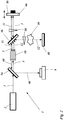
- FIG. 1 shows a first embodiment of the apparatus of the invention in a Mach-Zehnder-Interferometer configuration.
- a pump source 2 emits a pump beam 3, preferably a laser beam.
- the pump beam 3 is split on a pump beam separation means, here a pump beam splitter 6 splits the pump beam 3 into two coherent pump beams 3a and 3b.
- the pump beam splitter 6 can be a normal beam splitter or a polarizing beam splitter with an additional wave plate (not shown) to rotate the polarization of one of the pump beams 3a or 3b in order to pump a first and second field generation means 10 or 20.
- the polarization of the first and/or the second pump beams 3a and 3b can be rotated by a wave plate (not shown) to enable the pump of the first and second field generation means 10 and 20.
- a wave plate (not shown) to enable the pump of the first and second field generation means 10 and 20.
- the first pump beam 3a is guided into the first generation means 10 and the second pump beam 3b is guided by a first mirror 4a into the second generation means 20.
- a third dichroic mirror 5c is arranged allowing the second pump beam 3b to travel through the third dichroic mirror 5c.
- the first generation means 10 is pumped by the first pump beam 3a, generating a first signal field 11 and first idler field 12.
- the first pump beam 3a is blocked after the first generation means 10 by a first dichroic mirror 5a allowing the first signal field 11 and first idler field 12 to pass through.
- the first signal field 11 and first idler field 12 are then separated on a separation means, in figure 1 on a second dichroic mirror 5b.
- the first signal field 11 is transmitted through the second dichroic mirror 5b and travels guided by second mirror 4b, preferably by a movable mirror to a beam splitter 7.
- the first idler field 12 is reflected on the second dichroic mirror 5b and interacts by transmission and/or reflection with an object 30.
- the first idler field 12 is then guided by the third dichroic mirror 5c into the second generation means 20.
- the second generation means 20 is pumped by the second pump beam 3b, generating a second signal field 21 and second idler field 22.
- the first idler field 12 overlaps spatially with the second idler field 22, such that the two fields are indistinguishable.
- the second pump beam 3b and the overlapping first and second idler fields 12 and 22 are blocked by a fourth dichroic mirror 5d whereas the second signal field 21 is transmitted and guided on the beam splitter 7.
- a Mach-Zehnder-Interferometer is created with an upper and a lower interferometer-arm between the pump beam splitter 6 and the beam splitter 7.
- the first and second signal fields 11 and 21 interfere on the beam splitter 7.
- detection means preferably CCD cameras are arranged to detect the intensity pattern of the interfered signal field 40.
- the phase shift ⁇ is generated by one or more phase shifting means 50.
- phase shifting means 50 In figure 1 more phase shifting means 50 are depicted whereas only one but also more phase shifting means 50 can be arranged in the apparatus for imaging and spectroscopy 1. In figure 1 , only as an example, the phase shifting means 50 are shown on more places.
- the phase shifting means 50 can be the second mirror 4b by translation of the mirror preferably movable by a piezo element.
- the phase shifting means 50 can also be a fiber expander (for a fiber interferometer setup), and/or a tilting plane-parallel plate, and/or an optical element introducing a frequency difference between the two pump beams 3a and 3b, and/or an EOM (electro optic modulator) and/or wave plates and/or a polarizing beam splitter and/or a polarizer by changing the polarization, and/or plane-parallel plate by tilting the plate, and or a birefringent plate by tilting the plate.
- a fiber expander for a fiber interferometer setup
- a tilting plane-parallel plate and/or an optical element introducing a frequency difference between the two pump beams 3a and 3b
- EOM electro optic modulator
- phase shifting means 50 are in the first signal field s 1 11 and/or, in the second signal field s 2 21 and/or, in the first idler field i 1 12 and/or, in the second idler field i 2 22 and/or, in the first pump beam 3a and/or, in the second pump beam 3b.
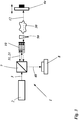
- FIG. 2 shows a second embodiment of the apparatus of the invention in a Fizeau -Interferometer configuration.
- the pump source 2 emits a pump beam 3 which is transmitted through a first dichroic mirror 5a and pumps a generation means 10, wherein the generation means 10 acts in this pump direction as a first generation means 10 and generates the first signal field 11 and the first idler field 12.
- the first signal field 11 and the pump beam 3 transmit through a second dichroic mirror 5b and are reflected on the first mirror 4a, preferably on the movable first mirror 4a. After the reflection on the first mirror 4a the signal field 11 and the pump beam 3 are transmitted through the dichroic mirror 5b a second time and are guided into the generation means 10.
- the first idler field 12 is reflected on the second dichroic mirror 5b and interacts with the object 30 by transmission and/or reflection and is guided by a second mirror 4b back on the second dichroic mirror 5b and is guided into the generation means 10.
- the generation means 10 acts as a second generation means by this pump direction generating the second signal field 21 and second idler field 22.
- the first signal field 11 and the second signal field 21 overlap spatially in and behind the generation means 10, such that the signal fields interfere.
- the first idler field 12 and the second idler field 22 overlap spatially in and behind the generation means, such that the paths of the first idler field 12 and the second idler field 22 are indistinguishable.
- the interfered signal fields 40 are reflected on the first dichroic mirror and detected by the detection means.
- phase shifting means 50 are depicted whereas only one but also more phase shifting means 50 can be arranged in the apparatus for imaging and spectroscopy 1.
- the phase shifting means 50 are shown on more places.
- the phase shifting means 50 can be the first mirror 4a by translation of the mirror, preferably movable by a piezo element.
- the phase shifting means 50 can be the second mirror 4b by translation of the mirror (not shown in Fig. 2 ), preferably movable by a piezo element.
- the phase shifting means 50 can also be a fiber expander (for a fiber interferometer setup), and/or a tilting plane-parallel plate, and/or an optical element introducing a frequency difference between the two pump beams 3a and 3b, and/or an EOM (electro optic modulator) and/or wave plates and/or a polarizing beam splitter and/or a polarizer by changing the polarization, and/or plane-parallel plate by tilting the plate, and or a birefringent plate by tilting the plate.
- a fiber expander for a fiber interferometer setup
- a tilting plane-parallel plate and/or an optical element introducing a frequency difference between the two pump beams 3a and 3b
- EOM electro optic modulator
- phase shifting means 50 are in the first signal field s 1 11 and/or in the first idler field i 1 12 and/or in the pump beam 3.
- Figure 3 shows a third embodiment of the apparatus of the invention in a Fizeau - Interferometer-like configuration.
- the difference to figure 2 is that in figure 3 the first dichroic mirror 5a is replaced by a beam splitter 7, and the first signal field 11 is reflected on the surface of the generation means 10 to change the pump direction for the generation of the second signal 21 and idler 22 fields. Only the first idler beam is transmitted through the surface, interacts with the object and is guided back in the generation means 10.
- Figure 4 shows a fourth embodiment of the apparatus of the invention in a Mach-Zehnder-Interferometer setup with BBO-crystals.
- the pump source 2 emits a pump beam 3 which is split into a first and a second pump beam 3a and 3b, whereas the polarization can be adjusted by a wave plate (not shown) to pump the first and second generation means 10 and 20.
- the first and second generation means 10 and 20 are BBO crystals, emitting the first signal field 11 and the first idler field 21 in the first generation means 10, and the second signal field 21 and the second idler field 22 in the second generation means 20 under a specific angle.
- the first generation means 10 pumped by the first pump beam 3a generates the first signal field 11 and the first idler field 21.
- the first signal field 11 is reflected on the first mirror 4a, preferably on a movable mirror and guides the first signal field 11 into the beam splitter 7.
- the first idler field 12 interacts with the object 30 by transmission and/or reflection and is guided into the second generation means 20.
- the second generation means 20 pumped by the second pump beam 3b generates the second signal field 21 and the second idler field 22.
- the first and second idler fields 12 and 22 overlap spatially in and behind the second generation means 20 such that the first and second idler fields 12 and 22 are indistinguishable.
- the second signal field 21 is guided to the beam splitter 7 and interferes with the first signal field 11 on the beam splitter.
- detection means 8 are arranged to detect the interfered signal fields 40.
- phase shifting means 50 are depicted whereas the only one or more phase shifting means 50 can be arranged in the apparatus for imaging and spectroscopy 1.
- the phase shifting means 50 are shown on more places.
- the phase shifting means can be the first mirror 4a by translation of the mirror, preferably movable by a piezo element.
- the phase shifting means 50 can also be a fiber expander (for a fiber interferometer setup), and/or a tilting plane-parallel plate, and/or an optical element introducing a frequency difference between the two pump beams 3a and 3b, and/or an EOM (electro optic modulator) and/or wave plates and/or a polarizing beam splitter and/or a polarizer by changing the polarization, and/or plane-parallel plate by tilting the plate, and or a birefringent plate by tilting the plate.
- a fiber expander for a fiber interferometer setup
- a tilting plane-parallel plate and/or an optical element introducing a frequency difference between the two pump beams 3a and 3b
- EOM electro optic modulator
- phase shifting means 50 are in the first signal field s 1 11 and/or in the second signal field s 2 21 and/or in the first idler field i 1 12 and/or, in the second idler field i 2 22 and/or in the first pump beam 3a and/or in the second pump beam 3b.
Landscapes
- Physics & Mathematics (AREA)
- General Physics & Mathematics (AREA)
- Spectroscopy & Molecular Physics (AREA)
- Health & Medical Sciences (AREA)
- Immunology (AREA)
- Biochemistry (AREA)
- General Health & Medical Sciences (AREA)
- Analytical Chemistry (AREA)
- Chemical & Material Sciences (AREA)
- Pathology (AREA)
- Life Sciences & Earth Sciences (AREA)
- Optics & Photonics (AREA)
- Nuclear Medicine, Radiotherapy & Molecular Imaging (AREA)
- Nonlinear Science (AREA)
- Instruments For Measurement Of Length By Optical Means (AREA)
- Investigating Or Analysing Materials By Optical Means (AREA)
- Optical Modulation, Optical Deflection, Nonlinear Optics, Optical Demodulation, Optical Logic Elements (AREA)
- Spectrometry And Color Measurement (AREA)
Abstract
Description
- The present invention provides an improvement method for imaging or spectroscopy with a non-linear interferometer according to
claim 1 and an improvement apparatus for imaging or spectroscopy according toclaim 10. - Non-linear interferometer allows probing an unknown object, preferably sample, at a particular wavelength, while detecting correlated light at the same or a different wavelength. In known non-linear interferometry systems, it is crucial to have an absolutely correct interferometer setting for perfectly determining the maximum constructive and destructive images. To get this, the interferometer must be adjusted before each measurement. This, for example, can be done by the measurement of the visibility of the interferometer to find the maximum constructive and/or destructive interference without the object in the setup.
- Due to stability drifts of the interferometer, the stability of the setup cannot be guaranteed for long operation times which results in a decrease of the interference visibility and a decrease of the precision of the measurement. The stability drifts can occur among other things due to thermal changes in the setup, mechanical and/or thermal instability of the components and even vibrations of the underground. For longer operation times in known systems the setup has to be readjusted to the maximum destructive and/or constructive interference or it is necessary to readjust the fringe center.
- It is an object of the present invention to provide an improved, more precise method for imaging or spectroscopy with a non-linear interferometer, also allowing longer measurement times and an improved more precise apparatus for imaging or spectroscopy.
- According to the present invention, a method for imaging and/or spectroscopy of an object is provided according to
claim 1. - The method comprises the steps
- i) generation of a first signal field s1 and a first idler field i1, by pumping a first non-linear medium with a pump beam, such that the two fields are correlated,
- ii) illumination of the object with the first idler i1 field, respectively by transmission and/or reflection,
- iii) generation of a second signal field s2 and a second idler field i2,
- by pumping a spatial separate second non-linear medium with the pump beam, or
- by pumping the first non-linear medium a second time with the pump beam, such that the two fields are correlated,
- iv) combination of the first i1 and second i2 idler fields, such that the two fields are indistinguishable, and
combination of the first s1 and second s2 signal fields, such that the two fields interfere, - v) first measurement of the interfered signal field s12 by a detection means,
- vi) one or more additional measurements of the interfered signal field s12 by the detection means,
- The invention further provides an apparatus for imaging and/or spectroscopy according to
claim 10. - The apparatus comprises a pump source to generate a pump beam, and
a first signal s1 and idler i1 field generation means pumped by the pump beam, and
a second signal s2 and idler i2 field generation means pumped by the pump beam, wherein the first and the second field generation means are - two spatial separated nonlinear media pumped by the pump beam, or
- one non-linear medium, pumped by the pump beam a first time to generate a first signal s1 and idler i1 field and pumped a second time to generate a second signal s2 and idler i2 field, and
- The present invention provides an improved solution to the known systems where it is not necessary to adjust and/or readjust the interferometer. Preferably it is not necessary to adjust the setup at the beginning of the measurement without the object in the setup and/or it is not necessary to readjust the system for longer measurements times than the stability time of the interferometer. Another advantage of this invention is that it is not necessary to find the interference fringe center for spectroscopy or the interferometer setting for constructive or destructive interference.
- Another advantage of the present invention is, that it is not necessary to set the phase at the beginning of the measurement to a specific value, for example to constructive and/or destructive interference. As an advantage in the present invention, the phase in the interferometer at the start of the measurement can be unknown and/or arbitrary.
- Another advantage of the present invention is when the measurements accuracy should be further improved or the measurement time should be further extended, the measurements of the step v) and vi) can be repeated a second time, or a third time, or a fourth time, or more times. The advantage of the present invention is that only each measurement unit (consisting of once the steps v) and vi)) has to be carried out within the stability time of the setup. A readjustment of the system is not necessary between the measurement units because the starting phase in the setup can be unknown. For the calculation in step vii) the measurements of the measurement units can be summed up when more measurement units are carried out.
- One principle of the present invention is to calculate the wave front phase at every measurement location from the time varying intensity measurement points. Time varying signals are detected and the relative phase is encoded in these signals. The phase shift between the fields is varied in a known manner during the data collection and the phase shift is taken into account for the calculation.
- In a preferred method and/or apparatus the first and/or second non-linear medium is a non-linear crystal, preferably a ppKTP crystal (periodically poled Potassium titanyl phosphate crystal), preferably a BBO crystal, preferably two crystals with the same physical and optical properties.
- In a preferred method in step i) and/or step iii) the signal and idler fields are separated by a separation means in or behind the crystal or are separated due to the generation of the signal and idler fields in the non-linear medium, respectively separated due to the generation of the fields in a BBO (β-Barium borate) crystal.
- In a preferred method and/or apparatus the phase matching conditions are fulfilled in the generation of the first signal s1 and idler i1 fields and/or the second signal s2 and idler i2 fields.
- In a preferred method and/or apparatus behind the first non-linear medium a separation means is arranged in the field path to separate the first signal s1 and idler i1 fields spatially.
- In a preferred method and/or apparatus the separation means is a dichroic mirror or a prism or a diffraction grating.
- In a preferred method and/or apparatus the pump beam is generated by a pump source comprising a coherent light source or a laser to produce a coherent light beam or a laser beam.
- Preferably, the pump source can comprise a coherent light source or a laser to produce the pump beam, respectively a coherent light beam or a laser beam.
- In a preferred method and/or apparatus the pump beam is separated into a first pump beam pumping the first non-linear medium and a second pump beam pumping the second non-linear medium, wherein the separation is realized by a pump beam separation means, preferably by a beam splitter or by a polarizing beam splitter with a wave plate.
- In a preferred method and/or apparatus the generation of the first and second signal s1, s2 and idler i1, i2 field is realized by induced coherence with and/or without induced emission, preferably by pumping the non-linear medium in low or high gain regime.
- In a preferred method and/or apparatus the correlated signal s1, s2 and idler i1, i2 fields are correlated photon beams or correlated photon pairs, respectively entangled photon pairs.
- In a preferred method and/or apparatus the first signal s1 field has the wavelength λs1 and the first idler i1 field has the wavelength λi1, and/or wherein the second signal s2 field has the wavelength λS2 and second idler field has the wavelength λi2. Preferably, the wavelength λs1 is equal to the wavelength λS2 and/or the is wavelength λi1 is equal to wavelength λi2. Preferably, the wavelengths λs1 and AS2 are different to the wavelengths λi1 and λi2. This allows probing an object at a particular wavelength while the measurement on the measurement means is carried out at a different wavelength.
- In a preferred method and/or apparatus the expression correlation is preferably understood in the meaning, that the first signal s1 and idler i1 fields and/or the second signal s2 and idler i2 fields are correlated in phase, and/or intensity, and/or amplitude, and/or coherence time, and/or momentum, and/or spatial, and/or spectral characteristics.
- In a preferred method and/or apparatus the first signal s1 field and the first idler i1 field are correlated by the generation of the two fields in the first non-linear medium. Preferably, the first signal s1 field and the first idler i1 field are correlated in phase, and/or intensity, and/or amplitude, and/or coherence time, and/or momentum, and/or spatial.
- In a preferred method and/or apparatus the second signal s2 field and the second idler i2 field are correlated by the generation of the two fields in the second non-linear medium. Preferably, the second signal s2 field and the second idler i2 field are correlated in phase, and/or intensity, and/or amplitude, and/or coherence time, and/or momentum, and/or spatial.
- In a preferred method and/or apparatus the expression indistinguishable is preferably understood in the meaning, that the fields are indistinguishable so that they interfere, preferably they are indistinguishable in all degrees of freedom, so that they interfere. The degree/s of freedom can be spatially, and/or in frequency, and/or in polarization, and/or in mode.
- In a preferred method and/or apparatus the interference of the first s1 and second s2 signal fields results from the indistinguishability of the first s1 and second s2 signal fields, preferably on an interference means, preferably a beam splitter or a polarizing beam splitter.
- In a preferred method and/or apparatus the interference of the first s1 and second s2 signal fields occurs due to the arrangement of the components to an interferometer. Preferably the components are arranged in a Mach-Zehnder interferometer configuration or an Fizeau-Interferometer configuration or a Michelson-Interferometer configuration.
- In a preferred method and/or apparatus the first and second idler i1, i2 fields are correlated, respectively by pumping the non-linear crystal/s with a coherent pump beam and/or by the indistinguishability of the two fields preferably they are indistinguishable in all degrees of freedom, so that they interfere. The degree/s of freedom can be spatially, and/or frequency, and/or in polarization, and/or in mode.
- In a preferred method and/or apparatus the first and second signal s1, s2 fields are correlated, respectively by pumping the first and second non-linear crystal with a coherent pump beam and/or by the indistinguishability of the two fields preferably they are indistinguishable in all degrees of freedom, so that they interfere. The degree/s of freedom can be spatially, and/or frequency, and/or in polarization, and/or in mode.
- In a preferred method and/or apparatus the spatial and spectral coherence of the pump fields and idler fields is such, that first-order interference between the first signal field s1 and the second signal field s2 can be observed. When the coherence time of the laser is shorter than the propagation time between
crystal 1 andcrystal 2, the required coherence of the generated fields can be achieved by introducing optical delays in the paths between the pump and the first idler field i1 and in addition the first-order interference between the first signal field s1 and the second signal field s2 condition has to be fulfilled. Here, pump preferably means the pump for the generation of a second signal field s2 and a second idler field i2 This means, it should be unknown in which crystal the field is generated. This can be obtained for example by perfect alignment of the idler field from the first crystal with the idler field from the second crystal. - In a preferred method and/or apparatus by the interference of the first s1 and second s2 signal fields an interfered signal field s12 is generated.
- In a preferred method and/or apparatus the combination of the first i1 and second i2 idler fields occurs in and/or behind the second non-linear medium or due to an idler combining means.
- In a preferred method and/or apparatus the combination of the first i1 and second i2 idler field is realized due to the spatial overlap of the first and second idler fields i1, i2. Preferably, the spatial overlap of the first and second idler fields i1, i2 is realized by a spatial overlap of the fields in and behind the non-linear medium or in an idler combining means, respectively a beam splitter and/or a dichroic mirror.
- In a preferred method and/or apparatus the combination of the first s1 and second s2 signal fields occurs due to a signal combining means.
- In a preferred method and/or apparatus the combination is of the first s1 and second s2 signal fields is realized due to the spatial overlap of the first and second idler fields i1, i2. Preferably, the spatial overlap of the first and second idler fields i1, i2 is realized by a signal combining means, respectively a beam splitter and/or a dichroic mirror.
- In a preferred method and/or apparatus the interference of the first and second signal fields s1, s2 is realized by a spatial overlap of the fields in a signal combining means, respectively by a beam splitter and/or a 50/50 beam splitter and/or a polarizing beam splitter and/or a dichroic mirror and/or by a spatial overlap of the fields behind the non-linear medium.
- In a preferred method and/or apparatus the signal and/or idler combining means comprises a beam splitter and/or a 50/50 beam splitter and/or a polarizing beam splitter and/or a dichroic mirror.
- In a preferred method and/or apparatus the measurements in step v) and step vi) are made for a specific point on or in the object.
- In a preferred method and/or apparatus the measurements in step v) and step vi) are made without moving the object, in order to not introduce an additional phase shift by the object due to the movement or a different measurement point on the object.
- In a preferred method and/or apparatus the phase shift α is created
- in the first signal field s1, and/or
- in the second signal field s2, and/or
- in the first idler field i1, and/or
- in the second idler field i2, and/or
- in the pump beam in front of the first non-linear medium, preferably in the first pump beam, and/or
- in the pump beam in front of the second non-linear medium, preferably in the second pump beam, and/or
- between the first and second signal fields i1 and i2, and/or
- between the first signal and idler fields s1 and i1, and/or
- between the first and the second pump beams, and/or
- in the interfered signal field s12.
- The preceding options all lead to the same result. Also, a combination, i.e. of several of the options leads to the same result.
- In a preferred method and/or apparatus the phase shift α is created by
- changing the path length of one or more field/s, and/or
- changing the wavelength of the first and/or second pump beam, and/or
- by thermal effects, and/or
- by spatial displacement or change of the optical path length in one or both interferometer arms.
- In a preferred method and/or apparatus in fiber the phase shift α is created by
- thermal effects, and/or
- changing the path length of one or more field/s, and/or
- changing the wavelength of the first and/or second pump beam, and/or
- mechanical stress in the fiber.
- In a preferred method and/or apparatus in step vi) different phase shift means that the phase shift α is added to the phase in step v) in the setup, preferably in the interferometer.
- In a preferred method and/or apparatus the phase in step v), preferably the phase of the setup, preferably of the interferometer in step v) is unknown and/or arbitrary.
- In a preferred method and/or apparatus the phase shifts can be introduced by a translation of a mirror and/or a translation of an optical surface and/or a translation of a dichroic mirror, respectively movable by a piezo element, and/or by a fiber expander, and/or by tilting a plane-parallel plate, and/or by an optical frequency difference between two beams, preferably two pump beams and/or by the change of the polarization by an EOM and/or wave plates and/or a polarizing beam splitter and/or a polarizer, and/or by tilting a plane-parallel plate, and or by a rotation or movement of a birefringent plate.
- In a preferred method and/or apparatus the stability time of the setup means that during the stability time the change of the visibility of the setup, preferably of the interferometer is in the range of 0,6 to 1, preferably in the range of 0,9 to 1, preferably in the range of 0,95 to 1.
- In a preferred method and/or apparatus the detection means is a CCD camera or a CMOS camera or a spectrometer or a fiber array or a SPAD array.
- In a preferred method and/or apparatus only the interfered signal field s12 detected on the detection means is used to calculate the phase function in step vii), preferably only the detection area of the detection means which detects the interfered signal field s12 is used to calculate the phase function in step vii).
- In a preferred method in step v) and/or vi) and/or apparatus the intensity and/or the phase and/or the amplitude of the interfered signal field s12 is measured.
- In a preferred method in step v) and/or vi) and/or apparatus the constructive and destructive interference is measured, respectively by a first and second detection means behind two output arms of an interference means, respectively a 50/50 beam splitter, respectively wherein the 50/50 beam splitter is the signal combining means. When the constructive and destructive interference is measured behind the interference means with two detection means according to the invention still an additional phase shift α is generated in the setup in step vi). The advantage of this embodiment is, that with one phase shift α and the detection of the constructive and destructive interference four measurement steps can be made. Preferably, the phase shift α is added in the measurement on the first output arm of the interference means (for example at the constructive interference) and the phase shift α is added in the measurement on the second output arm of the interference means (for example at the destructive interference).
- In a preferred method in step v) and/or vi) one detection means is used wherein for each measurement a phase shift α is generated, or two or more detection means are used, wherein for each additional detection means the same or a separate phase shift α is generated.
- In a preferred method and/or apparatus the detection means has a detection area, wherein the whole area is used for one specific measurement in step v) and/or vi), or wherein the area is split into more individual measurement areas, wherein for each individual measurement area a separate phase shift α is generated.
- In a preferred method the measurements in step v) and vi) are repeated for each point x, y of the object to calculate the phase function of the whole object Φ(x,y). The calculation of the phase function Φ of the objects can be made by calculations according to one of the following steps:
- In a preferred method and/or apparatus in step v) and vi) two measurements are performed with two different phases, meaning one phase shift α is generated.
- In a preferred method and/or apparatus in step v) and vi) three measurements are performed with three different phases, meaning two phase shifts α are generated.
- In a preferred method and/or apparatus in step v) and vi) four measurements are performed with four different phases, meaning three phase shifts α are generated.
- In a preferred method and/or apparatus in step v) and vi) five measurements are performed with five different phases, meaning four phase shifts α are generated.
- In a preferred method and/or apparatus in step v) and vi) six measurements are performed with six different phases, meaning five phase shifts α are generated.
- In a preferred method and/or apparatus in step v) and vi) two phase shifts α are generated with only one phase shift step and the measurement of the constructive and destructive interference, respectively by a first and second detection means behind two output arms of an interference means.
- In a preferred method the phase function Φ(x,y) is calculated by the measurements in step v) and vi), respectively by intensity measurements in step v) and vi) by


- In a preferred method the phase function Φ(x,y) is calculated by the measurements in step v) and vi), respectively by intensity measurements in step v) and vi) by

- In a preferred method the phase function Φ(x,y) is calculated by the measurements in step v) and vi), respectively by intensity measurements in step v) and vi) by


- In a preferred method the phase function Φ(x,y) is calculated by the measurements in step v) and vi), respectively by intensity measurements in step v) and vi) by


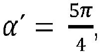
- In a preferred method the phase function Φ(x,y) is calculated by the measurements in step v) and vi), respectively by intensity measurements in step v) and vi) by

- In a preferred method in step vii) the phase distribution of the object is retrieved by the intensity pattern of the intensity measurements.
- In a preferred method and/or apparatus the setup can be designed as an in-fiber setup, preferably with an in-fiber pump, and an in-fiber generation of the fields, and in-fiber interference, and an in-fiber detection. Preferably for the object the first idler field is placed in a free space channel, formed by a first fiber coupler to couple the first idler field out of the fiber and a second fiber coupler to couple the first idler field into the fiber after the object.
- In a preferred method and/or apparatus the separation means and the signal combining means are arranged in a Mach-Zehnder interferometer configuration, respectively acting like beam splitter in a Mach-Zehnder interferometer.
- In a preferred method and/or apparatus the pump beam separation means and the signal combining means are arranged in a Mach-Zehnder interferometer configuration, respectively acting like beam splitter in a Mach-Zehnder interferometer.
- In a preferred method and/or apparatus in the Mach-Zehnder interferometer configuration the first field generation means is arranged before the separation means and behind the pump beam separation means, and
wherein the separation means separates the first signal s1 and idler i1 fields, and wherein the object is placed in the first idler i1 field, and
wherein the second field generation is arranged behind the object, and wherein in the combining means the first signal s1 fields and the second signal s2 fields interfere. - In a preferred method and/or apparatus in the Mach-Zehnder interferometer configuration the first field generation means and the interference means are arranged in a Mach-Zehnder interferometer configuration, respectively acting like beam splitter in a Mach-Zehnder interferometer. Wherein in one arm the second generation means is arranged. Wherein preferably the first and second generation means are BBO crystals.
- In a preferred method and/or apparatus the separation means and the signal combining means are arranged in a laser Fizeau interferometer configuration.
- In a preferred method and/or apparatus the separation means and the signal combining means are arranged in a laser Michelson-interferometer configuration.
- In a preferred method and/or apparatus the interferometer is a polarization interferometer, preferably two polarizations are each sent to one arm of the interferometer.
- In a preferred method and/or apparatus the phase shift α is created within the interferometer.
- The invention further provides an apparatus for imaging and/or spectroscopy adapted to provide one of the methods above.
- The invention further provides an apparatus with a control device adapted to provide one of the methods above, wherein the control device is connected to the phase shifter and to the detection means.
- The invention further provides a computer device with a microprocessor with a non-volatile memory, wherein the non-volatile memory comprises an executable program adapted to provide one of the methods above, preferably wherein the computer device is the control device.
- The above and other aspects, features and advantages of the present invention will become more apparent from the following detailed description when taken in conjunction with the accompanying drawings.
-
- Figure 1:
- A first embodiment of the apparatus of the invention in a Mach-Zehnder-Interferometer setup;
- Figure 2:
- A second embodiment of the apparatus of the invention in a Fizeau-Interferometer setup;
- Figure 3:
- A third embodiment of the apparatus of the invention;
- Figure 4:
- A fourth embodiment of the apparatus of the invention in a Mach-Zehnder-Interferometer setup with BBO-crystals.
-
Figure 1 shows a first embodiment of the apparatus of the invention in a Mach-Zehnder-Interferometer configuration. Apump source 2 emits apump beam 3, preferably a laser beam. Thepump beam 3 is split on a pump beam separation means, here apump beam splitter 6 splits thepump beam 3 into twocoherent pump beams pump beam splitter 6 can be a normal beam splitter or a polarizing beam splitter with an additional wave plate (not shown) to rotate the polarization of one of thepump beams second pump beams first pump beam 3a is guided into the first generation means 10 and thesecond pump beam 3b is guided by afirst mirror 4a into the second generation means 20. In the path of thesecond pump beam 3b a thirddichroic mirror 5c is arranged allowing thesecond pump beam 3b to travel through the thirddichroic mirror 5c. - As described above, the first generation means 10 is pumped by the
first pump beam 3a, generating afirst signal field 11 and firstidler field 12. Thefirst pump beam 3a is blocked after the first generation means 10 by a firstdichroic mirror 5a allowing thefirst signal field 11 and firstidler field 12 to pass through. - The
first signal field 11 and firstidler field 12 are then separated on a separation means, infigure 1 on a seconddichroic mirror 5b. Thefirst signal field 11 is transmitted through the seconddichroic mirror 5b and travels guided bysecond mirror 4b, preferably by a movable mirror to abeam splitter 7. - The
first idler field 12 is reflected on the seconddichroic mirror 5b and interacts by transmission and/or reflection with anobject 30. Thefirst idler field 12 is then guided by the thirddichroic mirror 5c into the second generation means 20. - The second generation means 20 is pumped by the
second pump beam 3b, generating asecond signal field 21 and second idler field 22. In and/or behind the second generation means 20 thefirst idler field 12 overlaps spatially with the second idler field 22, such that the two fields are indistinguishable. Thesecond pump beam 3b and the overlapping first and second idler fields 12 and 22 are blocked by a fourthdichroic mirror 5d whereas thesecond signal field 21 is transmitted and guided on thebeam splitter 7. - A Mach-Zehnder-Interferometer is created with an upper and a lower interferometer-arm between the
pump beam splitter 6 and thebeam splitter 7. - The first and second signal fields 11 and 21 interfere on the
beam splitter 7. On both outputs of thebeam splitter 7, detection means, preferably CCD cameras are arranged to detect the intensity pattern of the interferedsignal field 40. - The phase shift α is generated by one or more phase shifting means 50. In
figure 1 more phase shifting means 50 are depicted whereas only one but also more phase shifting means 50 can be arranged in the apparatus for imaging andspectroscopy 1. Infigure 1 , only as an example, the phase shifting means 50 are shown on more places. The phase shifting means 50 can be thesecond mirror 4b by translation of the mirror preferably movable by a piezo element. The phase shifting means 50 can also be a fiber expander (for a fiber interferometer setup), and/or a tilting plane-parallel plate, and/or an optical element introducing a frequency difference between the twopump beams - The possible places of the phase shifting means 50 are in the first signal field s1 11 and/or, in the second signal field s2 21 and/or, in the first idler field i1 12 and/or, in the second idler field i2 22 and/or, in the
first pump beam 3a and/or, in thesecond pump beam 3b. -
Figure 2 shows a second embodiment of the apparatus of the invention in a Fizeau -Interferometer configuration. Thepump source 2 emits apump beam 3 which is transmitted through a firstdichroic mirror 5a and pumps a generation means 10, wherein the generation means 10 acts in this pump direction as a first generation means 10 and generates thefirst signal field 11 and thefirst idler field 12. - The
first signal field 11 and thepump beam 3 transmit through a seconddichroic mirror 5b and are reflected on thefirst mirror 4a, preferably on the movablefirst mirror 4a. After the reflection on thefirst mirror 4a thesignal field 11 and thepump beam 3 are transmitted through thedichroic mirror 5b a second time and are guided into the generation means 10. - The
first idler field 12 is reflected on the seconddichroic mirror 5b and interacts with theobject 30 by transmission and/or reflection and is guided by asecond mirror 4b back on the seconddichroic mirror 5b and is guided into the generation means 10. - By the second time, the generation means is pumped from the right side in
figure 2 by thepump beam 3, the generation means 10 acts as a second generation means by this pump direction generating thesecond signal field 21 and second idler field 22. Thefirst signal field 11 and thesecond signal field 21 overlap spatially in and behind the generation means 10, such that the signal fields interfere. Thefirst idler field 12 and the second idler field 22 overlap spatially in and behind the generation means, such that the paths of thefirst idler field 12 and the second idler field 22 are indistinguishable. The interferedsignal fields 40 are reflected on the first dichroic mirror and detected by the detection means. - As in
figure 1 , here infigure 2 more phase shifting means 50 are depicted whereas only one but also more phase shifting means 50 can be arranged in the apparatus for imaging andspectroscopy 1. Infigure 2 , only as an example, the phase shifting means 50 are shown on more places. The phase shifting means 50 can be thefirst mirror 4a by translation of the mirror, preferably movable by a piezo element. The phase shifting means 50 can be thesecond mirror 4b by translation of the mirror (not shown inFig. 2 ), preferably movable by a piezo element. The phase shifting means 50 can also be a fiber expander (for a fiber interferometer setup), and/or a tilting plane-parallel plate, and/or an optical element introducing a frequency difference between the twopump beams - The possible places of the phase shifting means 50 are in the first signal field s1 11 and/or in the first idler field i1 12 and/or in the
pump beam 3. -
Figure 3 shows a third embodiment of the apparatus of the invention in a Fizeau - Interferometer-like configuration. The difference tofigure 2 is that infigure 3 the firstdichroic mirror 5a is replaced by abeam splitter 7, and thefirst signal field 11 is reflected on the surface of the generation means 10 to change the pump direction for the generation of thesecond signal 21 and idler 22 fields. Only the first idler beam is transmitted through the surface, interacts with the object and is guided back in the generation means 10. -
Figure 4 shows a fourth embodiment of the apparatus of the invention in a Mach-Zehnder-Interferometer setup with BBO-crystals. - The
pump source 2 emits apump beam 3 which is split into a first and asecond pump beam first signal field 11 and thefirst idler field 21 in the first generation means 10, and thesecond signal field 21 and the second idler field 22 in the second generation means 20 under a specific angle. - The first generation means 10 pumped by the
first pump beam 3a generates thefirst signal field 11 and thefirst idler field 21. Thefirst signal field 11 is reflected on thefirst mirror 4a, preferably on a movable mirror and guides thefirst signal field 11 into thebeam splitter 7. Thefirst idler field 12 interacts with theobject 30 by transmission and/or reflection and is guided into the second generation means 20. - The second generation means 20 pumped by the
second pump beam 3b generates thesecond signal field 21 and the second idler field 22. The first and second idler fields 12 and 22 overlap spatially in and behind the second generation means 20 such that the first and second idler fields 12 and 22 are indistinguishable. Thesecond signal field 21 is guided to thebeam splitter 7 and interferes with thefirst signal field 11 on the beam splitter. On both output arms of the beam splitter, detection means 8 are arranged to detect the interfered signal fields 40. - As before, here in
figure 4 more phase shifting means 50 are depicted whereas the only one or more phase shifting means 50 can be arranged in the apparatus for imaging andspectroscopy 1. Infigure 4 , only as an example, the phase shifting means 50 are shown on more places. The phase shifting means can be thefirst mirror 4a by translation of the mirror, preferably movable by a piezo element. The phase shifting means 50 can also be a fiber expander (for a fiber interferometer setup), and/or a tilting plane-parallel plate, and/or an optical element introducing a frequency difference between the twopump beams - The possible places of the phase shifting means 50 are in the first signal field s1 11 and/or in the second signal field s2 21 and/or in the first idler field i1 12 and/or, in the second idler field i2 22 and/or in the
first pump beam 3a and/or in thesecond pump beam 3b. - Die Forschungsarbeiten, die zu diesen Ergebnissen geführt haben, wurden von der Europäischen Union gefördert.
The project leading to this application has received funding from the European Union's Horizon 2020 research and innovation program under grant agreement No 801060. -
- 1
- apparatus for imaging and spectroscopy
- 2
- pump source
- 3
- pump beam
- 3a
- first pump beam
- 3b
- second pump beam
- 4a
- first mirror
- 4b
- second mirror
- 5a
- first dichroic mirror
- 5b
- second dichroic mirror
- 5c
- third dichroic mirror
- 5d
- fourth dichroic mirror
- 6
- pump beam splitter
- 7
- beam splitter (BS)
- 8
- detection means
- 10
- first field generation means
- 11
- first signal field
- 12
- first idler field
- 20
- second field generation means
- 21
- second signal field
- 22
- second idler field
- 30
- object
- 40
- interfered signal field
- 50
- phase shifter
wherein the first measurement in step v) and the one or more additional measurements in step vi) are all carried out within the stability time of the setup, vii) calculation of the phase function Φ out of the measurements from step v) and step vi) in order to get an image and/or a spectrum of the object.
a signal combining means to overlap the first signal s1 and second signal s2 fields, such that the two fields interfere, and
an idler combining means to overlap the first idler i1 and second idler i2 fields, such that the two fields are indistinguishable, and
a detection means to detect the intensity and/or phase of the interfered signal field. Whereby a phase shifter is arranged in the first signal s1 field, and/or in the second signal s2 field, and/or in the pump beam, and/or in the indistinguishable first and second signal fields s1 and s2, wherein the phase shifter is adapted to introduce a phase shift α in the apparatus during the measurement in order to get an image and/or a spectrum of the object.
Claims (15)
- Method for imaging and/or spectroscopy comprising the stepsi) generation of a first signal field s1 and a first idler field i1, by pumping a first non-linear medium with a pump beam, such that the two fields are correlated,ii) illumination of the object with the first idler i1 field, respectively by transmission and/or reflection,iii) generation of a second signal field s2 and a second idler field i2,- by pumping a spatial separate second non-linear medium with the pump beam, or- by pumping the first non-linear medium a second time with the pump beam,such that the two fields are correlated,iv) combination of the first i1 and second i2 idler fields, such that the two fields are indistinguishable, and
combination of the first s1 and second s2 signal fields, such that the two fields interfere,v) first measurement of the interfered signal field s12 by a detection means,vi) one or more additional measurements of the interfered signal field s12 by the detection means,
wherein for each additional measurement in step vi) a different phase shift α is generated in the setup, and
wherein the first measurement in step v) and the one or more additional measurements in step vi) are all carried out within the stability time of the setup,vii) calculation of the phase function Φ out of the measurements from step v) and step vi) in order to get an image and/or a spectrum of the object. - The method according to claim 1,
wherein the phase shift α is created- in the first signal field s1 and/or- in the second signal field s2 and/or- in the first idler field i1 and/or- in the second idler field i2 and/or- in the pump beam in front of the first non-linear medium, preferably in the first pump beam and/or- in the pump beam in front of the second non-linear medium, preferably in the second pump beam and/or- between the first and second signal fields i1 and i2 and/or- between the first signal and idler fields s1 and i1, and/or- between the first and the second pump beams, and/or- in the interfered signal field s12. - The method according to one of claims 1 or 2,
wherein the phase shift α is created by- changing the path length of one or more field/s, and/or- changing the wavelength of the first and/or second pump beam, and/or- by thermal effects, and/or- by spatial displacement or change of the optical path length in one or both interferometer arms. - The method according to one of claims 1 to 3,
wherein the phase shifts can be introduced by a translation of a mirror and/or a translation of an optical surface and/or a translation of a dichroic mirror, respectively movable by a piezo element, and/or by a fiber expander, and/or by tilting a plane-parallel plate, and/or by an optical frequency difference between two beams, preferably two pump beams and/or by the change of the polarization by an EOM and/or wave plates and/or a polarizing beam splitter and/or a polarizer, and/or by tilting a plane-parallel plate, and or by a rotation or movement of a birefringent plate. - The method according to one of claims 1 to 4,
wherein the phase of the setup in step v) is unknown and/or arbitrary. - The method according to one of claims 1 to 5,
wherein in step i) and/or step iii) the signal and idler fields are separated by a separation means in or behind the crystal or are separated due to the generation of the signal and idler fields in the non-linear medium, respectively separated due to the generation of the fields in a BBO crystal. - The method according to one of claims 1 to 6,
wherein in step v) and/or vi) and/or apparatus the constructive and destructive interference is measured, respectively by a first and second detection means behind two output arms of an interference means, respectively a 50/50 beam splitter, respectively wherein the 50/50 beam splitter is the signal combining means - The method according to one of claims 1 to 7,
wherein in step v) and/or vi) one detection means is used, wherein for each measurement a phase shift α is generated, or two or more detection means are used, wherein for each additional detection means the same or a separate phase shift α is generated. - Apparatus for imaging and/or spectroscopy adapted to provide one of the methods according to claims 1 to 8
- Apparatus for imaging and/or spectroscopy comprises
a pump source to generate a pump beam, and
a first signal s1 and idler i1 field generation means pumped by the pump beam, and
a second signal s2 and idler i2 field generation means pumped by the pump beam,
wherein the first and the second field generation means are- two spatial separated non-linear media pumped by the pump beam, or- one non-linear medium, pumped by the pump beam a first time to generate a first signal s1 and idler i1 field and pumped a second time to generate a second signal s2 and idler i2 field, andan object to be measured which is illuminated, respectively by transmission or reflection, by the first idler field i1, and
a signal combining means to overlap the first signal s1 and second signal s2 fields, such that the two fields interfere, and
an idler combining means to overlap the first idler i1 and second idler i2 fields, such that the two fields are indistinguishable, and
a detection means to detect the intensity and/or phase of the interfered signal field,
characterized in that,
a phase shifter is arranged in the first signal s1 field, and/or in the second signal s2 field, and/or in the pump beam, and/or in the indistinguishable first and second signal fields s1 and s2, wherein the phase shifter is adapted to introduce a phase shift α in the apparatus during the measurement in order to get an image and/or a spectrum of the object. - Apparatus according to claim 10,
wherein the phase shifts can be introduced by a movable mirror and/or a movable optical surface and/or a movable dichroic mirror, respectively movable by a piezo element, and/or by a fiber expander, and/or by a tiltable plane-parallel plate, and/or by an optical frequency difference between two beams, preferably two pump beams and/or by the change of the polarization by an EOM and/or wave plates and/or a polarizing beam splitter and/or a polarizer, and/or by a tiltable plane-parallel plate, and/or by a rotatable or moveable birefringent plate. - Apparatus according to claim 10,
wherein the separation means and the signal combining means are arranged in a Mach-Zehnder interferometer configuration or a laser Fizeau interferometer configuration, or a Michelson-interferometer configuration. - Apparatus according to claim 12,
wherein the phase shift α is created within the interferometer. - Apparatus according to one of claims 10 to 13,
wherein the apparatus comprises a control device adapted to provide one of the methods above, wherein the control device is connected to the phase shifter and to the detection means. - Computer device with a microprocessor with a non-volatile memory,
wherein the non-volatile memory comprises an executable program adapted to provide one of the methods above, preferably wherein the computer device is the control device.
Priority Applications (9)
| Application Number | Priority Date | Filing Date | Title |
|---|---|---|---|
| EP20159989.1A EP3872464B1 (en) | 2020-02-28 | 2020-02-28 | Method for imaging or spectroscopy with a non-linear interferometer |
| ES20159989T ES2982688T3 (en) | 2020-02-28 | 2020-02-28 | Imaging or spectroscopy procedure with a nonlinear interferometer |
| DK20159989.1T DK3872464T3 (en) | 2020-02-28 | 2020-02-28 | Method for imaging or spectroscopy with a nonlinear interferometer |
| JP2021025185A JP7340555B2 (en) | 2020-02-28 | 2021-02-19 | Methods for imaging or spectroscopy using nonlinear interferometry |
| CA3109688A CA3109688C (en) | 2020-02-28 | 2021-02-19 | Method for imaging or spectroscopy with a non-linear interferometer |
| US17/181,411 US11454541B2 (en) | 2020-02-28 | 2021-02-22 | Method for imaging or spectroscopy with a non-linear interferometer |
| SG10202101815PA SG10202101815PA (en) | 2020-02-28 | 2021-02-23 | Method for imaging or spectroscopy with a non-linear interferometer |
| KR1020210026622A KR102533874B1 (en) | 2020-02-28 | 2021-02-26 | Method for imaging or spectroscopy with a non-linear interferometer |
| CN202110217232.2A CN113324951B (en) | 2020-02-28 | 2021-02-26 | Method for imaging or spectroscopic analysis using nonlinear interferometers |
Applications Claiming Priority (1)
| Application Number | Priority Date | Filing Date | Title |
|---|---|---|---|
| EP20159989.1A EP3872464B1 (en) | 2020-02-28 | 2020-02-28 | Method for imaging or spectroscopy with a non-linear interferometer |
Publications (2)
| Publication Number | Publication Date |
|---|---|
| EP3872464A1 true EP3872464A1 (en) | 2021-09-01 |
| EP3872464B1 EP3872464B1 (en) | 2024-05-22 |
Family
ID=69742885
Family Applications (1)
| Application Number | Title | Priority Date | Filing Date |
|---|---|---|---|
| EP20159989.1A Active EP3872464B1 (en) | 2020-02-28 | 2020-02-28 | Method for imaging or spectroscopy with a non-linear interferometer |
Country Status (9)
| Country | Link |
|---|---|
| US (1) | US11454541B2 (en) |
| EP (1) | EP3872464B1 (en) |
| JP (1) | JP7340555B2 (en) |
| KR (1) | KR102533874B1 (en) |
| CN (1) | CN113324951B (en) |
| CA (1) | CA3109688C (en) |
| DK (1) | DK3872464T3 (en) |
| ES (1) | ES2982688T3 (en) |
| SG (1) | SG10202101815PA (en) |
Families Citing this family (6)
| Publication number | Priority date | Publication date | Assignee | Title |
|---|---|---|---|---|
| US12055439B2 (en) * | 2019-12-13 | 2024-08-06 | Kyoto University | Quantum absorption spectroscopy system and quantum absorption spectroscopy method |
| WO2023053896A1 (en) * | 2021-09-29 | 2023-04-06 | 国立大学法人京都大学 | Quantum absorption spectroscopy system, and quantum absorption spectroscopy method |
| CN119156525A (en) * | 2022-03-08 | 2024-12-17 | 株式会社岛津制作所 | Spectroscopic device |
| CN115373141B (en) * | 2022-09-08 | 2025-03-25 | 南京大学 | An interaction-free, single-pixel quantum imaging system for undetected photons |
| CN115839929B (en) * | 2022-11-01 | 2025-12-19 | 中国人民解放军国防科技大学 | Magneto-optical polarization imaging measurement system with high space-time resolution |
| DE102023108849A1 (en) * | 2023-04-06 | 2024-10-10 | Humboldt-Universität zu Berlin, Körperschaft des öffentlichen Rechts | Optical arrangement and method for generating a measuring signal |
Citations (2)
| Publication number | Priority date | Publication date | Assignee | Title |
|---|---|---|---|---|
| US20180180401A1 (en) * | 2015-09-08 | 2018-06-28 | Institut National De La Recherche Scientifique | System and method for phase-readout and active stabilization of optical interferometers |
| WO2020015809A1 (en) * | 2018-07-16 | 2020-01-23 | Max-Planck-Gesellschaft zur Förderung der Wissenschaften e. V. | Interferometry with an achromatic interferometric superposition of electromagnetic fields |
Family Cites Families (13)
| Publication number | Priority date | Publication date | Assignee | Title |
|---|---|---|---|---|
| US6931212B2 (en) * | 2000-12-22 | 2005-08-16 | Lucent Technologies Inc. | 3R optical signal regeneration |
| US7538887B1 (en) * | 2006-10-26 | 2009-05-26 | Kla-Tencor Corporation | Temporal interferometric signal modeling with constant phase shift in white light interferometry |
| KR100860947B1 (en) * | 2007-06-08 | 2008-09-30 | 한국표준과학연구원 | Infrared Nonlinear Molecular Vibration Spectroscopy Imaging Device |
| JP2013057619A (en) * | 2011-09-09 | 2013-03-28 | Canon Inc | Measurement apparatus and measurement method |
| JP2015215313A (en) * | 2014-05-13 | 2015-12-03 | キヤノン株式会社 | Measuring apparatus and article manufacturing method |
| CN105676558A (en) * | 2014-11-19 | 2016-06-15 | 华东师范大学 | Non-linear interferometer based on optical parameter process |
| SG11201807118YA (en) * | 2016-03-14 | 2018-09-27 | Agency Science Tech & Res | Optical system, method of forming and operating the same |
| CA3026091A1 (en) * | 2016-06-02 | 2017-12-07 | Massachusetts Institute Of Technology | Apparatus and methods for optical neural network |
| JP2018205430A (en) * | 2017-05-31 | 2018-12-27 | 国立研究開発法人産業技術総合研究所 | Phase shift digital holography apparatus and program thereof |
| JP2019191087A (en) * | 2018-04-27 | 2019-10-31 | 株式会社日立ハイテクサイエンス | Interference signal phase correction method |
| DE102018010364A1 (en) * | 2018-07-27 | 2020-01-30 | Q.ant GmbH | Laser light source and laser projector with it |
| CN109539975A (en) * | 2018-11-14 | 2019-03-29 | 哈尔滨工业大学 | Single frequency laser interferometer nonlinearity erron modification method and device |
| CN109814318B (en) * | 2019-03-20 | 2020-07-28 | 南开大学 | Quantum spiral imaging system |
-
2020
- 2020-02-28 EP EP20159989.1A patent/EP3872464B1/en active Active
- 2020-02-28 ES ES20159989T patent/ES2982688T3/en active Active
- 2020-02-28 DK DK20159989.1T patent/DK3872464T3/en active
-
2021
- 2021-02-19 CA CA3109688A patent/CA3109688C/en active Active
- 2021-02-19 JP JP2021025185A patent/JP7340555B2/en active Active
- 2021-02-22 US US17/181,411 patent/US11454541B2/en active Active
- 2021-02-23 SG SG10202101815PA patent/SG10202101815PA/en unknown
- 2021-02-26 KR KR1020210026622A patent/KR102533874B1/en active Active
- 2021-02-26 CN CN202110217232.2A patent/CN113324951B/en active Active
Patent Citations (2)
| Publication number | Priority date | Publication date | Assignee | Title |
|---|---|---|---|---|
| US20180180401A1 (en) * | 2015-09-08 | 2018-06-28 | Institut National De La Recherche Scientifique | System and method for phase-readout and active stabilization of optical interferometers |
| WO2020015809A1 (en) * | 2018-07-16 | 2020-01-23 | Max-Planck-Gesellschaft zur Förderung der Wissenschaften e. V. | Interferometry with an achromatic interferometric superposition of electromagnetic fields |
Non-Patent Citations (1)
| Title |
|---|
| GABRIELA BARRETO LEMOS ET AL: "Quantum imaging with undetected photons", NATURE, vol. 512, no. 7515, 28 August 2014 (2014-08-28), London, pages 409 - 412, XP055422298, ISSN: 0028-0836, DOI: 10.1038/nature13586 * |
Also Published As
| Publication number | Publication date |
|---|---|
| CN113324951A (en) | 2021-08-31 |
| US11454541B2 (en) | 2022-09-27 |
| EP3872464B1 (en) | 2024-05-22 |
| CA3109688A1 (en) | 2021-08-28 |
| KR20210110518A (en) | 2021-09-08 |
| CN113324951B (en) | 2024-08-20 |
| ES2982688T3 (en) | 2024-10-17 |
| KR102533874B1 (en) | 2023-05-18 |
| SG10202101815PA (en) | 2021-09-29 |
| CA3109688C (en) | 2023-08-22 |
| JP7340555B2 (en) | 2023-09-07 |
| JP2021139890A (en) | 2021-09-16 |
| US20210270671A1 (en) | 2021-09-02 |
| DK3872464T3 (en) | 2024-08-26 |
Similar Documents
| Publication | Publication Date | Title |
|---|---|---|
| US11454541B2 (en) | Method for imaging or spectroscopy with a non-linear interferometer | |
| US8363226B2 (en) | Optical interference measuring apparatus | |
| JP5421013B2 (en) | Positioning device and positioning method | |
| JP2017181259A (en) | Pulse light waveform measurement method and waveform measurement device | |
| US20110134525A1 (en) | Dual-beam laser processing system | |
| CN108873007A (en) | A kind of FM-CW laser ranging device inhibiting dither effect | |
| CN111194419A (en) | Additional imaging module for off-axis recording of polarization encoded waves | |
| JP5588769B2 (en) | Optical measuring device | |
| EP2899816B1 (en) | Method and device for time synchronization of picosecond and subpicosecond laser pulses | |
| US6249350B1 (en) | Interferometer and methods for compensation of dispersion or increase in spectral resolution of such an interferometer | |
| US20020085265A1 (en) | Hyper-heterodyning, expanded bandpass apparatus and method | |
| CN100552375C (en) | Simultaneous phase-shifting Fizeau interferometer | |
| US20250020446A1 (en) | Laser architecture for component efficient atomic interferometer gravimeter | |
| US20120236315A1 (en) | Polarization interferometer | |
| JP2011007802A (en) | Optical frequency measurement system | |
| US10379223B2 (en) | Fourier analysis by spectral transformation (Fast) Photonic Doppler Velocimetry (PDV) with signal fade mitigation | |
| WO2004032294A1 (en) | Frequency stabilized laser system comprising phase modulation of backscattered light | |
| JP2018537678A (en) | Method for measuring the relative delay between optical propagation channels in pulsed operation | |
| US20020085742A1 (en) | Multi-domain, photonic fingerprint analyzer | |
| JPH06317478A (en) | Optical wavelength / frequency detector | |
| US6671053B1 (en) | Illumination measuring device | |
| JPH05302810A (en) | Heterodyne two wave lengths displacement interference meter | |
| US20020085207A1 (en) | Hyper-resolution, topographic, holographic imaging apparatus and method | |
| JPH08320456A (en) | Polarization azimuth rotation device | |
| JP3955557B2 (en) | Optical sampling head |
Legal Events
| Date | Code | Title | Description |
|---|---|---|---|
| PUAI | Public reference made under article 153(3) epc to a published international application that has entered the european phase |
Free format text: ORIGINAL CODE: 0009012 |
|
| STAA | Information on the status of an ep patent application or granted ep patent |
Free format text: STATUS: THE APPLICATION HAS BEEN PUBLISHED |
|
| AK | Designated contracting states |
Kind code of ref document: A1 Designated state(s): AL AT BE BG CH CY CZ DE DK EE ES FI FR GB GR HR HU IE IS IT LI LT LU LV MC MK MT NL NO PL PT RO RS SE SI SK SM TR |
|
| STAA | Information on the status of an ep patent application or granted ep patent |
Free format text: STATUS: REQUEST FOR EXAMINATION WAS MADE |
|
| 17P | Request for examination filed |
Effective date: 20211109 |
|
| RBV | Designated contracting states (corrected) |
Designated state(s): AL AT BE BG CH CY CZ DE DK EE ES FI FR GB GR HR HU IE IS IT LI LT LU LV MC MK MT NL NO PL PT RO RS SE SI SK SM TR |
|
| RAP3 | Party data changed (applicant data changed or rights of an application transferred) |
Owner name: FRAUNHOFER-GESELLSCHAFT ZUR FOERDERUNG DER ANGEWANDTEN FORSCHUNG E.V. |
|
| GRAP | Despatch of communication of intention to grant a patent |
Free format text: ORIGINAL CODE: EPIDOSNIGR1 |
|
| STAA | Information on the status of an ep patent application or granted ep patent |
Free format text: STATUS: GRANT OF PATENT IS INTENDED |
|
| INTG | Intention to grant announced |
Effective date: 20230301 |
|
| GRAJ | Information related to disapproval of communication of intention to grant by the applicant or resumption of examination proceedings by the epo deleted |
Free format text: ORIGINAL CODE: EPIDOSDIGR1 |
|
| STAA | Information on the status of an ep patent application or granted ep patent |
Free format text: STATUS: REQUEST FOR EXAMINATION WAS MADE |
|
| INTC | Intention to grant announced (deleted) | ||
| GRAP | Despatch of communication of intention to grant a patent |
Free format text: ORIGINAL CODE: EPIDOSNIGR1 |
|
| STAA | Information on the status of an ep patent application or granted ep patent |
Free format text: STATUS: GRANT OF PATENT IS INTENDED |
|
| INTG | Intention to grant announced |
Effective date: 20240102 |
|
| GRAS | Grant fee paid |
Free format text: ORIGINAL CODE: EPIDOSNIGR3 |
|
| GRAA | (expected) grant |
Free format text: ORIGINAL CODE: 0009210 |
|
| STAA | Information on the status of an ep patent application or granted ep patent |
Free format text: STATUS: THE PATENT HAS BEEN GRANTED |
|
| P01 | Opt-out of the competence of the unified patent court (upc) registered |
Effective date: 20240403 |
|
| AK | Designated contracting states |
Kind code of ref document: B1 Designated state(s): AL AT BE BG CH CY CZ DE DK EE ES FI FR GB GR HR HU IE IS IT LI LT LU LV MC MK MT NL NO PL PT RO RS SE SI SK SM TR |
|
| REG | Reference to a national code |
Ref country code: GB Ref legal event code: FG4D |
|
| REG | Reference to a national code |
Ref country code: CH Ref legal event code: EP |
|
| REG | Reference to a national code |
Ref country code: DE Ref legal event code: R096 Ref document number: 602020031165 Country of ref document: DE |
|
| REG | Reference to a national code |
Ref country code: IE Ref legal event code: FG4D |
|
| REG | Reference to a national code |
Ref country code: DK Ref legal event code: T3 Effective date: 20240820 |
|
| REG | Reference to a national code |
Ref country code: LT Ref legal event code: MG9D |
|
| REG | Reference to a national code |
Ref country code: AT Ref legal event code: UEP Ref document number: 1689131 Country of ref document: AT Kind code of ref document: T Effective date: 20240522 |
|
| REG | Reference to a national code |
Ref country code: NL Ref legal event code: MP Effective date: 20240522 |
|
| PG25 | Lapsed in a contracting state [announced via postgrant information from national office to epo] |
Ref country code: IS Free format text: LAPSE BECAUSE OF FAILURE TO SUBMIT A TRANSLATION OF THE DESCRIPTION OR TO PAY THE FEE WITHIN THE PRESCRIBED TIME-LIMIT Effective date: 20240922 |
|
| PG25 | Lapsed in a contracting state [announced via postgrant information from national office to epo] |
Ref country code: BG Free format text: LAPSE BECAUSE OF FAILURE TO SUBMIT A TRANSLATION OF THE DESCRIPTION OR TO PAY THE FEE WITHIN THE PRESCRIBED TIME-LIMIT Effective date: 20240522 |
|
| PG25 | Lapsed in a contracting state [announced via postgrant information from national office to epo] |
Ref country code: HR Free format text: LAPSE BECAUSE OF FAILURE TO SUBMIT A TRANSLATION OF THE DESCRIPTION OR TO PAY THE FEE WITHIN THE PRESCRIBED TIME-LIMIT Effective date: 20240522 Ref country code: FI Free format text: LAPSE BECAUSE OF FAILURE TO SUBMIT A TRANSLATION OF THE DESCRIPTION OR TO PAY THE FEE WITHIN THE PRESCRIBED TIME-LIMIT Effective date: 20240522 |
|
| PG25 | Lapsed in a contracting state [announced via postgrant information from national office to epo] |
Ref country code: GR Free format text: LAPSE BECAUSE OF FAILURE TO SUBMIT A TRANSLATION OF THE DESCRIPTION OR TO PAY THE FEE WITHIN THE PRESCRIBED TIME-LIMIT Effective date: 20240823 |
|
| PG25 | Lapsed in a contracting state [announced via postgrant information from national office to epo] |
Ref country code: PT Free format text: LAPSE BECAUSE OF FAILURE TO SUBMIT A TRANSLATION OF THE DESCRIPTION OR TO PAY THE FEE WITHIN THE PRESCRIBED TIME-LIMIT Effective date: 20240923 |
|
| PG25 | Lapsed in a contracting state [announced via postgrant information from national office to epo] |
Ref country code: NL Free format text: LAPSE BECAUSE OF FAILURE TO SUBMIT A TRANSLATION OF THE DESCRIPTION OR TO PAY THE FEE WITHIN THE PRESCRIBED TIME-LIMIT Effective date: 20240522 |
|
| REG | Reference to a national code |
Ref country code: ES Ref legal event code: FG2A Ref document number: 2982688 Country of ref document: ES Kind code of ref document: T3 Effective date: 20241017 |
|
| PG25 | Lapsed in a contracting state [announced via postgrant information from national office to epo] |
Ref country code: PL Free format text: LAPSE BECAUSE OF FAILURE TO SUBMIT A TRANSLATION OF THE DESCRIPTION OR TO PAY THE FEE WITHIN THE PRESCRIBED TIME-LIMIT Effective date: 20240522 |
|
| PG25 | Lapsed in a contracting state [announced via postgrant information from national office to epo] |
Ref country code: LV Free format text: LAPSE BECAUSE OF FAILURE TO SUBMIT A TRANSLATION OF THE DESCRIPTION OR TO PAY THE FEE WITHIN THE PRESCRIBED TIME-LIMIT Effective date: 20240522 |
|
| PG25 | Lapsed in a contracting state [announced via postgrant information from national office to epo] |
Ref country code: PT Free format text: LAPSE BECAUSE OF FAILURE TO SUBMIT A TRANSLATION OF THE DESCRIPTION OR TO PAY THE FEE WITHIN THE PRESCRIBED TIME-LIMIT Effective date: 20240923 Ref country code: PL Free format text: LAPSE BECAUSE OF FAILURE TO SUBMIT A TRANSLATION OF THE DESCRIPTION OR TO PAY THE FEE WITHIN THE PRESCRIBED TIME-LIMIT Effective date: 20240522 Ref country code: NO Free format text: LAPSE BECAUSE OF FAILURE TO SUBMIT A TRANSLATION OF THE DESCRIPTION OR TO PAY THE FEE WITHIN THE PRESCRIBED TIME-LIMIT Effective date: 20240822 Ref country code: NL Free format text: LAPSE BECAUSE OF FAILURE TO SUBMIT A TRANSLATION OF THE DESCRIPTION OR TO PAY THE FEE WITHIN THE PRESCRIBED TIME-LIMIT Effective date: 20240522 Ref country code: LV Free format text: LAPSE BECAUSE OF FAILURE TO SUBMIT A TRANSLATION OF THE DESCRIPTION OR TO PAY THE FEE WITHIN THE PRESCRIBED TIME-LIMIT Effective date: 20240522 Ref country code: IS Free format text: LAPSE BECAUSE OF FAILURE TO SUBMIT A TRANSLATION OF THE DESCRIPTION OR TO PAY THE FEE WITHIN THE PRESCRIBED TIME-LIMIT Effective date: 20240922 Ref country code: HR Free format text: LAPSE BECAUSE OF FAILURE TO SUBMIT A TRANSLATION OF THE DESCRIPTION OR TO PAY THE FEE WITHIN THE PRESCRIBED TIME-LIMIT Effective date: 20240522 Ref country code: GR Free format text: LAPSE BECAUSE OF FAILURE TO SUBMIT A TRANSLATION OF THE DESCRIPTION OR TO PAY THE FEE WITHIN THE PRESCRIBED TIME-LIMIT Effective date: 20240823 Ref country code: FI Free format text: LAPSE BECAUSE OF FAILURE TO SUBMIT A TRANSLATION OF THE DESCRIPTION OR TO PAY THE FEE WITHIN THE PRESCRIBED TIME-LIMIT Effective date: 20240522 Ref country code: BG Free format text: LAPSE BECAUSE OF FAILURE TO SUBMIT A TRANSLATION OF THE DESCRIPTION OR TO PAY THE FEE WITHIN THE PRESCRIBED TIME-LIMIT Effective date: 20240522 Ref country code: RS Free format text: LAPSE BECAUSE OF FAILURE TO SUBMIT A TRANSLATION OF THE DESCRIPTION OR TO PAY THE FEE WITHIN THE PRESCRIBED TIME-LIMIT Effective date: 20240822 |
|
| PG25 | Lapsed in a contracting state [announced via postgrant information from national office to epo] |
Ref country code: EE Free format text: LAPSE BECAUSE OF FAILURE TO SUBMIT A TRANSLATION OF THE DESCRIPTION OR TO PAY THE FEE WITHIN THE PRESCRIBED TIME-LIMIT Effective date: 20240522 |
|
| PG25 | Lapsed in a contracting state [announced via postgrant information from national office to epo] |
Ref country code: CZ Free format text: LAPSE BECAUSE OF FAILURE TO SUBMIT A TRANSLATION OF THE DESCRIPTION OR TO PAY THE FEE WITHIN THE PRESCRIBED TIME-LIMIT Effective date: 20240522 |
|
| PG25 | Lapsed in a contracting state [announced via postgrant information from national office to epo] |
Ref country code: SK Free format text: LAPSE BECAUSE OF FAILURE TO SUBMIT A TRANSLATION OF THE DESCRIPTION OR TO PAY THE FEE WITHIN THE PRESCRIBED TIME-LIMIT Effective date: 20240522 Ref country code: RO Free format text: LAPSE BECAUSE OF FAILURE TO SUBMIT A TRANSLATION OF THE DESCRIPTION OR TO PAY THE FEE WITHIN THE PRESCRIBED TIME-LIMIT Effective date: 20240522 |
|
| PG25 | Lapsed in a contracting state [announced via postgrant information from national office to epo] |
Ref country code: SM Free format text: LAPSE BECAUSE OF FAILURE TO SUBMIT A TRANSLATION OF THE DESCRIPTION OR TO PAY THE FEE WITHIN THE PRESCRIBED TIME-LIMIT Effective date: 20240522 |
|
| PG25 | Lapsed in a contracting state [announced via postgrant information from national office to epo] |
Ref country code: SM Free format text: LAPSE BECAUSE OF FAILURE TO SUBMIT A TRANSLATION OF THE DESCRIPTION OR TO PAY THE FEE WITHIN THE PRESCRIBED TIME-LIMIT Effective date: 20240522 Ref country code: SK Free format text: LAPSE BECAUSE OF FAILURE TO SUBMIT A TRANSLATION OF THE DESCRIPTION OR TO PAY THE FEE WITHIN THE PRESCRIBED TIME-LIMIT Effective date: 20240522 Ref country code: RO Free format text: LAPSE BECAUSE OF FAILURE TO SUBMIT A TRANSLATION OF THE DESCRIPTION OR TO PAY THE FEE WITHIN THE PRESCRIBED TIME-LIMIT Effective date: 20240522 Ref country code: EE Free format text: LAPSE BECAUSE OF FAILURE TO SUBMIT A TRANSLATION OF THE DESCRIPTION OR TO PAY THE FEE WITHIN THE PRESCRIBED TIME-LIMIT Effective date: 20240522 Ref country code: CZ Free format text: LAPSE BECAUSE OF FAILURE TO SUBMIT A TRANSLATION OF THE DESCRIPTION OR TO PAY THE FEE WITHIN THE PRESCRIBED TIME-LIMIT Effective date: 20240522 |
|
| REG | Reference to a national code |
Ref country code: DE Ref legal event code: R097 Ref document number: 602020031165 Country of ref document: DE |
|
| PLBE | No opposition filed within time limit |
Free format text: ORIGINAL CODE: 0009261 |
|
| STAA | Information on the status of an ep patent application or granted ep patent |
Free format text: STATUS: NO OPPOSITION FILED WITHIN TIME LIMIT |
|
| PG25 | Lapsed in a contracting state [announced via postgrant information from national office to epo] |
Ref country code: SI Free format text: LAPSE BECAUSE OF FAILURE TO SUBMIT A TRANSLATION OF THE DESCRIPTION OR TO PAY THE FEE WITHIN THE PRESCRIBED TIME-LIMIT Effective date: 20240522 |
|
| 26N | No opposition filed |
Effective date: 20250225 |
|
| PG25 | Lapsed in a contracting state [announced via postgrant information from national office to epo] |
Ref country code: SE Free format text: LAPSE BECAUSE OF FAILURE TO SUBMIT A TRANSLATION OF THE DESCRIPTION OR TO PAY THE FEE WITHIN THE PRESCRIBED TIME-LIMIT Effective date: 20240522 |
|
| PG25 | Lapsed in a contracting state [announced via postgrant information from national office to epo] |
Ref country code: MC Free format text: LAPSE BECAUSE OF FAILURE TO SUBMIT A TRANSLATION OF THE DESCRIPTION OR TO PAY THE FEE WITHIN THE PRESCRIBED TIME-LIMIT Effective date: 20240522 |
|
| REG | Reference to a national code |
Ref country code: DK Ref legal event code: EBP Effective date: 20250228 |
|
| REG | Reference to a national code |
Ref country code: CH Ref legal event code: PL |
|
| PG25 | Lapsed in a contracting state [announced via postgrant information from national office to epo] |
Ref country code: LU Free format text: LAPSE BECAUSE OF NON-PAYMENT OF DUE FEES Effective date: 20250228 |
|
| PG25 | Lapsed in a contracting state [announced via postgrant information from national office to epo] |
Ref country code: CH Free format text: LAPSE BECAUSE OF NON-PAYMENT OF DUE FEES Effective date: 20250228 |
|
| GBPC | Gb: european patent ceased through non-payment of renewal fee |
Effective date: 20250228 |
|
| REG | Reference to a national code |
Ref country code: BE Ref legal event code: MM Effective date: 20250228 |
|
| PG25 | Lapsed in a contracting state [announced via postgrant information from national office to epo] |
Ref country code: GB Free format text: LAPSE BECAUSE OF NON-PAYMENT OF DUE FEES Effective date: 20250228 |
|
| PG25 | Lapsed in a contracting state [announced via postgrant information from national office to epo] |
Ref country code: DK Free format text: LAPSE BECAUSE OF NON-PAYMENT OF DUE FEES Effective date: 20250228 |
|
| PG25 | Lapsed in a contracting state [announced via postgrant information from national office to epo] |
Ref country code: IT Free format text: LAPSE BECAUSE OF NON-PAYMENT OF DUE FEES Effective date: 20250228 |
|
| PG25 | Lapsed in a contracting state [announced via postgrant information from national office to epo] |
Ref country code: BE Free format text: LAPSE BECAUSE OF NON-PAYMENT OF DUE FEES Effective date: 20250228 |
|
| PG25 | Lapsed in a contracting state [announced via postgrant information from national office to epo] |
Ref country code: IE Free format text: LAPSE BECAUSE OF NON-PAYMENT OF DUE FEES Effective date: 20250228 |
|
| REG | Reference to a national code |
Ref country code: ES Ref legal event code: FD2A Effective date: 20260330 |
|
| PG25 | Lapsed in a contracting state [announced via postgrant information from national office to epo] |
Ref country code: ES Free format text: LAPSE BECAUSE OF NON-PAYMENT OF DUE FEES Effective date: 20250228 |
|
| PGFP | Annual fee paid to national office [announced via postgrant information from national office to epo] |
Ref country code: DE Payment date: 20260217 Year of fee payment: 7 |
|
| PGFP | Annual fee paid to national office [announced via postgrant information from national office to epo] |
Ref country code: AT Payment date: 20260216 Year of fee payment: 7 |
|
| PGFP | Annual fee paid to national office [announced via postgrant information from national office to epo] |
Ref country code: FR Payment date: 20260219 Year of fee payment: 7 |