EP3872234A1 - Hydrogen-generating electrode responsive to load fluctuation and method of manufacturing the same - Google Patents
Hydrogen-generating electrode responsive to load fluctuation and method of manufacturing the same Download PDFInfo
- Publication number
- EP3872234A1 EP3872234A1 EP20198733.6A EP20198733A EP3872234A1 EP 3872234 A1 EP3872234 A1 EP 3872234A1 EP 20198733 A EP20198733 A EP 20198733A EP 3872234 A1 EP3872234 A1 EP 3872234A1
- Authority
- EP
- European Patent Office
- Prior art keywords
- electrode
- hydrogen
- metal
- base material
- transition metal
- Prior art date
- Legal status (The legal status is an assumption and is not a legal conclusion. Google has not performed a legal analysis and makes no representation as to the accuracy of the status listed.)
- Withdrawn
Links
Images






Classifications
-
- C—CHEMISTRY; METALLURGY
- C25—ELECTROLYTIC OR ELECTROPHORETIC PROCESSES; APPARATUS THEREFOR
- C25B—ELECTROLYTIC OR ELECTROPHORETIC PROCESSES FOR THE PRODUCTION OF COMPOUNDS OR NON-METALS; APPARATUS THEREFOR
- C25B11/00—Electrodes; Manufacture thereof not otherwise provided for
- C25B11/04—Electrodes; Manufacture thereof not otherwise provided for characterised by the material
- C25B11/051—Electrodes formed of electrocatalysts on a substrate or carrier
- C25B11/073—Electrodes formed of electrocatalysts on a substrate or carrier characterised by the electrocatalyst material
- C25B11/091—Electrodes formed of electrocatalysts on a substrate or carrier characterised by the electrocatalyst material consisting of at least one catalytic element and at least one catalytic compound; consisting of two or more catalytic elements or catalytic compounds
-
- C—CHEMISTRY; METALLURGY
- C25—ELECTROLYTIC OR ELECTROPHORETIC PROCESSES; APPARATUS THEREFOR
- C25B—ELECTROLYTIC OR ELECTROPHORETIC PROCESSES FOR THE PRODUCTION OF COMPOUNDS OR NON-METALS; APPARATUS THEREFOR
- C25B1/00—Electrolytic production of inorganic compounds or non-metals
- C25B1/01—Products
- C25B1/02—Hydrogen or oxygen
- C25B1/04—Hydrogen or oxygen by electrolysis of water
-
- C—CHEMISTRY; METALLURGY
- C25—ELECTROLYTIC OR ELECTROPHORETIC PROCESSES; APPARATUS THEREFOR
- C25B—ELECTROLYTIC OR ELECTROPHORETIC PROCESSES FOR THE PRODUCTION OF COMPOUNDS OR NON-METALS; APPARATUS THEREFOR
- C25B1/00—Electrolytic production of inorganic compounds or non-metals
- C25B1/01—Products
- C25B1/34—Simultaneous production of alkali metal hydroxides and chlorine, oxyacids or salts of chlorine, e.g. by chlor-alkali electrolysis
- C25B1/46—Simultaneous production of alkali metal hydroxides and chlorine, oxyacids or salts of chlorine, e.g. by chlor-alkali electrolysis in diaphragm cells
-
- C—CHEMISTRY; METALLURGY
- C25—ELECTROLYTIC OR ELECTROPHORETIC PROCESSES; APPARATUS THEREFOR
- C25B—ELECTROLYTIC OR ELECTROPHORETIC PROCESSES FOR THE PRODUCTION OF COMPOUNDS OR NON-METALS; APPARATUS THEREFOR
- C25B11/00—Electrodes; Manufacture thereof not otherwise provided for
- C25B11/04—Electrodes; Manufacture thereof not otherwise provided for characterised by the material
- C25B11/051—Electrodes formed of electrocatalysts on a substrate or carrier
- C25B11/052—Electrodes comprising one or more electrocatalytic coatings on a substrate
-
- C—CHEMISTRY; METALLURGY
- C25—ELECTROLYTIC OR ELECTROPHORETIC PROCESSES; APPARATUS THEREFOR
- C25B—ELECTROLYTIC OR ELECTROPHORETIC PROCESSES FOR THE PRODUCTION OF COMPOUNDS OR NON-METALS; APPARATUS THEREFOR
- C25B11/00—Electrodes; Manufacture thereof not otherwise provided for
- C25B11/04—Electrodes; Manufacture thereof not otherwise provided for characterised by the material
- C25B11/051—Electrodes formed of electrocatalysts on a substrate or carrier
- C25B11/055—Electrodes formed of electrocatalysts on a substrate or carrier characterised by the substrate or carrier material
- C25B11/057—Electrodes formed of electrocatalysts on a substrate or carrier characterised by the substrate or carrier material consisting of a single element or compound
- C25B11/061—Metal or alloy
-
- C—CHEMISTRY; METALLURGY
- C25—ELECTROLYTIC OR ELECTROPHORETIC PROCESSES; APPARATUS THEREFOR
- C25B—ELECTROLYTIC OR ELECTROPHORETIC PROCESSES FOR THE PRODUCTION OF COMPOUNDS OR NON-METALS; APPARATUS THEREFOR
- C25B11/00—Electrodes; Manufacture thereof not otherwise provided for
- C25B11/04—Electrodes; Manufacture thereof not otherwise provided for characterised by the material
- C25B11/051—Electrodes formed of electrocatalysts on a substrate or carrier
- C25B11/055—Electrodes formed of electrocatalysts on a substrate or carrier characterised by the substrate or carrier material
- C25B11/069—Electrodes formed of electrocatalysts on a substrate or carrier characterised by the substrate or carrier material consisting of at least one single element and at least one compound; consisting of two or more compounds
-
- C—CHEMISTRY; METALLURGY
- C25—ELECTROLYTIC OR ELECTROPHORETIC PROCESSES; APPARATUS THEREFOR
- C25B—ELECTROLYTIC OR ELECTROPHORETIC PROCESSES FOR THE PRODUCTION OF COMPOUNDS OR NON-METALS; APPARATUS THEREFOR
- C25B11/00—Electrodes; Manufacture thereof not otherwise provided for
- C25B11/04—Electrodes; Manufacture thereof not otherwise provided for characterised by the material
- C25B11/051—Electrodes formed of electrocatalysts on a substrate or carrier
- C25B11/073—Electrodes formed of electrocatalysts on a substrate or carrier characterised by the electrocatalyst material
- C25B11/075—Electrodes formed of electrocatalysts on a substrate or carrier characterised by the electrocatalyst material consisting of a single catalytic element or catalytic compound
- C25B11/089—Alloys
-
- Y—GENERAL TAGGING OF NEW TECHNOLOGICAL DEVELOPMENTS; GENERAL TAGGING OF CROSS-SECTIONAL TECHNOLOGIES SPANNING OVER SEVERAL SECTIONS OF THE IPC; TECHNICAL SUBJECTS COVERED BY FORMER USPC CROSS-REFERENCE ART COLLECTIONS [XRACs] AND DIGESTS
- Y02—TECHNOLOGIES OR APPLICATIONS FOR MITIGATION OR ADAPTATION AGAINST CLIMATE CHANGE
- Y02E—REDUCTION OF GREENHOUSE GAS [GHG] EMISSIONS, RELATED TO ENERGY GENERATION, TRANSMISSION OR DISTRIBUTION
- Y02E60/00—Enabling technologies; Technologies with a potential or indirect contribution to GHG emissions mitigation
- Y02E60/30—Hydrogen technology
- Y02E60/36—Hydrogen production from non-carbon containing sources, e.g. by water electrolysis
Definitions
- the present disclosure relates to an electrode (hydrogen evolution electrode) that generates hydrogen upon electrolysis of water or chlorine-alkali, and more particularly, to a hydrogen evolution electrode including a phosphide-based transition metal catalyst layer and a method of manufacturing the hydrogen evolution electrode.
- Electrodes for electrolysis processes are associated with hydrogen evolution reaction (HER) at a cathode in chlorine-alkali or water electrolysis.
- a cathode consists of a catalyst and a metal substrate coated with the catalyst.
- the metal substrate is formed of, for example, nickel (Ni), copper (Cu), or steel, and the surface of the metal substrate is coated with a catalyst containing ruthenium (Ru), platinum (Pt), or other precious metals as a basic component.
- Ru ruthenium
- Pt platinum
- the protective layers are each formed of an alloy consisting of one or more metal selected from nickel (Ni), cobalt (Co), and chromium (Cr) and one or more nonmetals selected from phosphorus (P) and boron (B), and the catalyst layer contains the oxide of rhenium (Re) or molybdenum (Mo), which is a non-precious metal transition element, a platinum-group metal, an oxide (ruthenium dioxide, RuO 2 ), and the like.
- the present disclosure has been made in view of the above problems, and it is an object of the present disclosure to provide a hydrogen-generating electrode having high catalytic activity comparable to that of a precious metal and high durability during reverse current reaction.
- a hydrogen-evolution electrode including a phosphide-based metal catalyst layer formed on a conductive base material, wherein the catalyst layer is formed of an amorphous alloy including a transition metal.
- the catalyst layer may further include a sacrificial metal having lower standard reduction potential than that of the transition metal.
- the conductive base material may be nickel (Ni), stainless steel 316L, or copper (Cu).
- the transition metal may be cobalt (Co).
- the sacrificial metal may be chromium (Cr) or manganese (Mn).
- the catalyst layer may include 80 to 90 wt% of the transition metal, 5 to 10 wt% of the sacrificial metal, and 5 to 10 wt% of phosphorus (P).
- a method of manufacturing a hydrogen-evolution electrode including preparing a catalyst solution including a transition metal solution and a phosphide solution; and forming a catalyst layer on a conductive base material using the catalyst solution.
- the catalyst solution may further include a sacrificial metal solution having lower standard reduction potential than that of the transition metal.
- the transition metal may be cobalt (Co).
- the sacrificial metal may be chromium (Cr) or manganese (Mn).
- the conductive base material may be nickel (Ni), stainless steel 316L, or copper (Cu).
- the conductive base material may be stainless steel 316L, and nickel (Ni) strike plating may be performed on a surface of the stainless steel 316L.
- a hydrogen-generating electrode includes a phosphide-based metal catalyst layer formed on a conductive base material.
- the catalyst layer includes a transition metal and phosphorus (P).
- the catalyst layer is formed of an amorphous alloy.
- the catalyst layer may further include a sacrificial metal having lower standard reduction potential than that of the transition metal. More specifically, the catalyst layer may include a transition metal, phosphorus (P), and a sacrificial metal having lower standard reduction potential than that of the transition metal.
- the phosphide-based metal may be an alloy composed of phosphorus (P) and a metal element.
- the transition metal may be a metal (active metal species) that exhibits activity in hydrogen generation reaction.
- Metals having lower standard reduction potential than that of the sacrificial metal may be used as the anode sacrificial material of a hydrogen-generating electrode catalyst, and the sacrificial metal may be a metal that does not have corrosion resistance against strong bases.
- the conductive base material may be nickel (Ni), stainless steel 316L, or copper (Cu).
- the transition metal may be cobalt (Co), iron (Fe), or nickel (Ni).
- the sacrificial metal may be chromium (Cr) or manganese (Mn).
- the sacrificial metal represented by chromium (Cr) or manganese (Mn) has lower standard reduction potential than that of the transition metal including cobalt (Co), iron (Fe), or nickel (Ni), and does not have corrosion resistance against strong bases. Accordingly, an amorphous alloy composed of chromium (Cr) or manganese (Mn), the transition metal such as cobalt (Co), iron (Fe), or nickel (Ni), and phosphorus (P) may be used the sacrificial anode material of a hydrogen-generating electrode catalyst.
- the sacrificial metal functions as the sacrificial anode material, does not inhibit the activity of an active metal (transition metal) for hydrogen generation reaction, and is oxidized instead of the active metal when reverse current is generated, so that the activity of a cathode is maintained.
- an active metal transition metal
- a metal transition metal having activity for hydrogen generation reaction is present. Accordingly, the hydrogen generation efficiency of the electrode may be maintained at a high level. This will be described in more detail as follows.
- the catalyst layer may include 80 to 90 wt% of the transition metal, 5 to 10 wt% of the sacrificial metal, and 5 to 10 wt% of the phosphorus (P).
- a method of manufacturing a hydrogen-generating electrode includes a step of preparing a catalyst solution including a transition metal solution, a phosphide solution, and a sacrificial metal solution having lower standard reduction potential than that of the transition metal; and a step of forming a catalyst layer on a conductive base material using the catalyst solution.
- the transition metal may be cobalt (Co), iron (Fe), or nickel (Ni).
- the sacrificial metal may be chromium (Cr) or manganese (Mn).
- the conductive base material may be nickel (Ni), stainless steel 316L, or copper (Cu).
- the step of forming the catalyst layer may be performed through electroplating, electroless plating, hydrothermal synthesis, or chemical bath deposition.
- the step of forming the catalyst layer may be performed through electroplating.
- the catalyst solution may be used as a plating solution
- the ratio of the transition metal ion to phosphite in the catalyst solution may be 0.01 to 0.5
- the applied current density may be 1 to 120 mA/cm 2
- electroplating may be performed at a temperature of 30 to 50 °C.
- the conductive base material may be stainless steel 316L, and nickel (Ni) strike plating may be performed on the surface of the stainless steel 316L.
- nickel strike plating By performing nickel strike plating, the bonding strength of the catalyst layer formed on stainless steel 316L, which is the conductive base material, may be improved.
- Ni nickel
- the Ni base material was sequentially pre-treated with 30 wt% of NaOH and 20 wt% of HCl before plating to remove impurities and oxide films present on the surface of the Ni base material.
- a plating solution was prepared by adding 1.2 M sodium hypophosphite monohydrate (NaH 2 PO 2 ⁇ H 2 O, Sigma-Aldrich) as a phosphorus (P) source and 0.6 M cobalt (II) chloride hexahydrate (CoCl 2 ⁇ 6H 2 O, JUNSEI) as a cobalt (Co) source to distilled water (DI water).
- Ni was used as a counter electrode, a plated surface area was 1.77 cm 2 , and plating was performed at room temperature for 450 seconds.
- the ratio of [Co 2+ ]/[H 2 PO 2 - ] in the plating solution was 0.5, the applied current density was 120 mA/cm 2 , and temperature was 30 °C.
- the electrode was washed with distilled water, followed by drying for more than 1 hour under vacuum.
- the weight ratio of P was 4 wt% and the weight ratio of Co was 96 wt%. Accordingly, in the catalyst layer formed on the final electrode, the atomic ratio of P was 6 at% and the atomic ratio of Co was 94 at% (Co 0.94 P 0.6 ).
- Nickel strike plating was performed on the surface of a stainless steel (SUS) 316L base material, and then electroplating was performed on nickel plated on the surface of the stainless steel 316L base material in the same manner as in Example 1 to manufacture a CoP electrode.
- the stainless steel 316L base material was sequentially pre-treated with 30 wt% of NaOH and 20 wt% of HCl to remove impurities and oxide films present on the surface of the stainless steel 316L base material.
- the weight ratio of P was 4 wt% and the weight ratio of Co was 96 wt%. Accordingly, in the catalyst layer formed on the final electrode, the atomic ratio of P was 6 at% and the atomic ratio of Co was 94 at% (Co 0.94 P 0.6 ).
- Ni nickel
- CoMnP CoMnP
- the Ni base material was sequentially pre-treated with 30 wt% of NaOH and 20 wt% of HCl to remove impurities and oxide films present on the surface of the Ni base material.
- a plating solution was prepared by adding, based on 1 L of the plating solution, 1.2 mol (1.2 M) sodium hypophosphite monohydrate (NaH 2 PO 2 ⁇ H 2 O, Sigma-Aldrich) as a phosphorus (P) source, 0.6 mol (0.6 M) cobalt (II) chloride hexahydrate (CoCl 2 ⁇ 6H 2 O, JUNSEI) as a cobalt (Co) source, and 0.06 mol (0.06 M) manganese chloride tetrahydrate (MnCl 2 ⁇ 4H 2 O, JUNSEI) to distilled water (DI water) as a solvent.
- 1.2 mol (1.2 M) sodium hypophosphite monohydrate (NaH 2 PO 2 ⁇ H 2 O, Sigma-Aldrich) as a phosphorus (P) source 0.6 mol (0.6 M) cobalt (II) chloride hexahydrate (CoCl 2 ⁇ 6H 2 O, J
- Ni was used as a counter electrode, a plated surface area was 1.77 cm 2 , and plating was performed at room temperature for 450 seconds.
- the ratio of [Co 2+ ]/[H 2 PO 2 - ] in the plating solution was 0.5, the applied current density was 120 mA/cm 2 , and temperature was 30 °C.
- the electrode was washed with distilled water, followed by drying for more than 1 hour under vacuum.
- the weight ratio of Mn was 5 wt%
- the weight ratio of P was 5 wt%
- the weight ratio of Co was 90 wt%.
- the atomic ratio of Mn was 5 at%
- the atomic ratio of P was 9 at%
- the atomic ratio of Co was 86 at% (Co 0.86 Mn 0.05 P 0.09 ).
- Nickel strike plating was performed on the surface of a stainless steel (SUS) 316L base material, and then electroplating was performed on nickel plated on the stainless steel 316L base material in the same manner as in Example 3 to manufacture a CoMnP electrode.
- the stainless steel 316L base material was sequentially pre-treated with 30 wt% of NaOH and 20 wt% of HCl to remove impurities and oxide films present on the surface of the stainless steel 316L base material.
- the weight ratio of Mn was 5 wt%
- the weight ratio of P was 5 wt%
- the weight ratio of Co was 90 wt%.
- the atomic ratio of Mn was 5 at%
- the atomic ratio of P was 9 at%
- the atomic ratio of Co was 86 at% (Co 0.86 Mn 0.05 P 0.09 ).
- the stainless steel 316L base material was sequentially pre-treated with 30 wt% of NaOH and 20 wt% of HCl to remove impurities and oxide films present on the surface of the base material.
- Nickel strike plating was performed on the surface of a stainless steel (SUS) 316L base material, and then electroplating was performed on nickel plated on the stainless steel 316L base material as in the same manner as in in in Example 3 to prepare a CoCrP electrode, except that CrCl 2 was used instead of MnCl 2 .
- the stainless steel 316L base material was sequentially pre-treated with 30 wt% of NaOH and 20 wt% of HCl to remove impurities and oxide films present on the surface of the stainless steel 316L base material.
- the weight ratio of Mn was 5 wt%
- the weight ratio of P was 5 wt%
- the weight ratio of Co was 90 wt%.
- the atomic ratio of Mn was 5 at%
- the atomic ratio of P was 9 at%
- the atomic ratio of Co was 86 at% (Co 0.86 Mn 0.05 P 0.09 ).
- Electrode base material Plating composition Plating solution Example 1 Ni CoP NaH 2 PO 2 ⁇ H 2 O + CoCl 2 ⁇ 6H 2 O
- Example 2 Stainless steel 316L + Ni strike plating CoP NaH 2 PO 2 ⁇ H 2 O + CoCl 2 ⁇ 6H 2 O
- Example 3 Ni CoMnP NaH 2 PO 2 ⁇ H 2 O + CoCl 2 ⁇ 6H 2 O + MnCl 2 ⁇ 4H 2 O
- Example 5 Stainless steel 316L + Ni strike plating CoCrP NaH 2 PO 2 ⁇ H 2 O + CoCl 2 ⁇ 6H 2 O + CrCl 2 ⁇ 4H 2 O
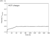
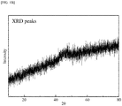
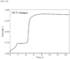
- FIGS. 1A and 1B The hydrogen generation open circuit voltage (OCV) characteristics and the XRD analysis results of the CoP electrode manufactured in Example 1 are shown in FIGS. 1A and 1B , and the open circuit voltage (OCV) characteristics and the XRD analysis results of a CoP electrode having a crystal structure as a comparative example are shown in FIGS. 1C and 1D .
- FIGS. 1A and 1C show open circuit voltage (OCV) characteristics
- FIGS. 1B and 1D show XRD analysis results.
- FIGS. 1A and 1B in the case of the amorphous CoP electrode manufactured in Example 1, potential rise (oxidation reaction of Co catalyst) width over time is relatively small, and potential rise is slow ( FIG. 1A ). In addition, no crystalline peak is observed. Thus, it can be seen that the CoP electrode has an amorphous structure ( FIG. 1B ).
- FIGS. 1C and 1D in the case of the CoP electrode having a crystalline structure as a comparative example, potential change over time is significant, showing rapid potential rise for a short time (about 5 hours) ( FIG. 1C ), peaks are observed at (100), (101), (110), and (200), and the hexagonal close packed (HCP) crystal structure of Co is shown ( FIG. 1D ).
- HCP hexagonal close packed
- a scanning electron microscope image for analyzing the composition of a CoMnP catalyst in the CoMnP electrode manufactured in Example 3 and a scanning electron microscope (SEM)-energy dispersive X-ray spectroscope (EDS) image for Mn, P, and Co were obtained, and the obtained images are shown in FIG. 3 ((a): SEM image showing surface of CoMnP catalyst, (b): EDS image of Mn, (c): EDS image of P, and (d): EDS image of Co).
- Performance change was measured using a three electrode system.
- the CoP electrode manufactured in Example 1 and the CoMnP electrode manufactured in Example 3 were used as working electrodes
- Hg/HgO was used as a reference electrode
- a platinum (Pt) mesh was used as a counter electrode
- performance change was measured at 25 °C in a 1M KOH electrolyte at a scan rate of 1 mV/s.
- FIG. 4A The measured results are shown in FIG. 4A .
- performance change (blue line) for hydrogen generation reaction when the surface of a metal (nickel) base material is plated only with Mn is shown as an additional control group.
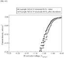
- the results of FIG. 4B are similar to those shown in FIG. 4A . More specifically, during water electrolysis operation (initial), the CoMnP electrode/SUS according to Example 4 shows no difference in activity (water electrolysis performance) compared to the CoP electrode/SUS (Example 2). In the case of the CoMnP electrode/SUS (Example 4), when measuring performance again after maintaining a condition of 5-hour operation stop (after shut-down), there is no activity change (performance deterioration) for hydrogen generation reaction. However, in the case of the CoP electrode/SUS (Example 2), when measuring performance again after maintaining a condition of 5-hour operation stop (after shut-down), overvoltage is observed, indicating deterioration in performance.
- the results of FIG. 4C are similar to those shown in FIG. 4A . More specifically, during water electrolysis operation (initial), when measuring performance again after maintaining a condition of 5-hour operation stop (after shut-down), the CoCrP electrode (CoCrP electrode/SUS) according to Example 5 exhibits little change in activity (insignificant degradation in performance) for hydrogen generation reaction.
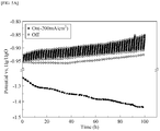
- Example 1 The CoP electrode manufactured in Example 1 and the CoMnP electrode manufactured in Example 3 were used as working electrodes, Hg/HgO was used as a reference electrode, a platinum (Pt) mesh was used as a counter electrode, and durability according to operation ('on' or 'Before shut-down')/stop ('off' or 'After shut-down') at 25 °C in a 1 M KOH electrolyte was evaluated. The obtained results are shown in FIG. 5A (Example 1), FIG. 5B (Example 1), FIG. 5C (Example 3) and FIG. 5D (Example 3).
- Example 1 CoP electrode
- voltage continuously increased from -0.95 V to -0.85 V deterioration.
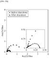
- FIG. 5B as a result of impedance analysis, in comparison with operation ('Before shut-down' in FIG. 5B ) before durability evaluation, after operation is stopped after durability evaluation('After shut-down' in FIG. 5B ), the size of the semicircle, which indicates deterioration in performance of the electrode, greatly increases.
- Example 3 CoMnP electrode
- voltage is -1.3 V.
- measured voltage is maintained at -0.90 V (performance maintenance).
- FIG. 5D as a result of impedance analysis, in comparison with operation before durability evaluation ('Before shut-down' in FIG. 5D ), after operation is stopped after durability evaluation ('After shut-down' in FIG. 5D ), the size of the semicircle, which indicates deterioration in performance of the electrode, does not increase significantly.
- Experimental Example 6 was performed in the same manner as in Experimental Example 4.
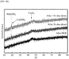
- durability was evaluated using linear sweep voltammetry (LSV) immediately after hydrogen generation reaction (during operation) (After HER), 5 hours after stopping operation (After 5 h shut-down), and 15 hours after stopping operation (After 15 h shut-down).
- LSV linear sweep voltammetry
- For each condition immediate after hydrogen generation reaction (during operation) (After HER), 5 hours after stopping operation (After 5 h shut-down), and 15 hours after stopping operation (After 15 h shut-down)
- XRD X-ray diffraction
- Example 3 For the electrodes manufactured in Example 3 (CoMnP electrode), Example 4 (CoMnP electrode), and Example 5 (CoCrP electrode), five samples per each electrode were prepared, and an accelerated life test was performed at 80 °C in a 30 wt% KOH electrolyte in a repeated on/off cycle condition wherein operation was performed at a current density of 400 mA/cm 2 (on) for 1 hour and then operation was performed at 0 mA/cm 2 (off or shut-down) for 30 minutes.
- hydrogen generation efficiency comparable to that of a precious metal can be secured using a transition metal and a non-precious metal.
Landscapes
- Chemical & Material Sciences (AREA)
- Engineering & Computer Science (AREA)
- Chemical Kinetics & Catalysis (AREA)
- Electrochemistry (AREA)
- Materials Engineering (AREA)
- Metallurgy (AREA)
- Organic Chemistry (AREA)
- Inorganic Chemistry (AREA)
- Electrodes For Compound Or Non-Metal Manufacture (AREA)
- Electrolytic Production Of Non-Metals, Compounds, Apparatuses Therefor (AREA)
Abstract
Description
- This application claims priority to Korean Patent Application No.
10-2020-0025171, filed on February 28, 2020 - The present disclosure relates to an electrode (hydrogen evolution electrode) that generates hydrogen upon electrolysis of water or chlorine-alkali, and more particularly, to a hydrogen evolution electrode including a phosphide-based transition metal catalyst layer and a method of manufacturing the hydrogen evolution electrode.
- Electrodes for electrolysis processes, particularly cathodes suitable for hydrogen generation in industrial electrolysis processes, are associated with hydrogen evolution reaction (HER) at a cathode in chlorine-alkali or water electrolysis. Typically, a cathode consists of a catalyst and a metal substrate coated with the catalyst. In this case, the metal substrate is formed of, for example, nickel (Ni), copper (Cu), or steel, and the surface of the metal substrate is coated with a catalyst containing ruthenium (Ru), platinum (Pt), or other precious metals as a basic component. In
US Patents No. 4,465,580 and No.4,238,311 , coating based on ruthenium oxide mixed with nickel oxide, catalyst coating based on any platinum-nickel alloy and rhenium (Re) or molybdenum (Mo), catalyst coating based on molybdenum oxide, and other types of catalyst coating for application to a metal substrate suitable for promoting hydrogen generation are disclosed. However, most of these formulations show a rather short operating lifespan in typical industrial applications due to poor coating adhesion to metal substrates. - In recent years, a number of studies are underway to secure activity equivalent to a precious metal by performing electroless deposition of an alloy composed of a metal, such as nickel (Ni), cobalt (Co), and iron (Fe), and an element, such as phosphorus (P) and boron (B). However, durability against reverse current that may occur when stopping in an electrolytic cell has not yet been secured. Moreover, detachment of catalyst coating on a substrate causes significant decrease in electrolytic cell efficiency. As a representative conventional technique for improving durability associated with reverse current, there is a method of using a conductive substrate sequentially coated with a first intermediate protective layer, a catalyst layer, and a second external protective layer as a hydrogen-generating electrode. In this case, the protective layers are each formed of an alloy consisting of one or more metal selected from nickel (Ni), cobalt (Co), and chromium (Cr) and one or more nonmetals selected from phosphorus (P) and boron (B), and the catalyst layer contains the oxide of rhenium (Re) or molybdenum (Mo), which is a non-precious metal transition element, a platinum-group metal, an oxide (ruthenium dioxide, RuO2), and the like. As other methods, there are a method of replacing an electrolyte in contact with an electrode with a liquid having very low electrical conductivity when stopped and a method of improving durability using an electrode including a ruthenium oxide layer or a nickel oxide layer that absorbs reverse current generated when an electrolysis device is stopped.
-
- Korean Patent Application Publication No.
10-207-0013409 (February 06, 2017 - Korean Patent No.
10-1614639 (April 15, 2016 - Japanese Patent Application Publication No.
2011-511158 (April 07, 2011 - Japanese Patent No.
5876811 (January 29, 2016 - Japanese Patent No.
6438741 (November 22, 2018 - Therefore, the present disclosure has been made in view of the above problems, and it is an object of the present disclosure to provide a hydrogen-generating electrode having high catalytic activity comparable to that of a precious metal and high durability during reverse current reaction.
- In accordance with one aspect of the present disclosure, provided is a hydrogen-evolution electrode including a phosphide-based metal catalyst layer formed on a conductive base material, wherein the catalyst layer is formed of an amorphous alloy including a transition metal.
- The catalyst layer may further include a sacrificial metal having lower standard reduction potential than that of the transition metal.
- The conductive base material may be nickel (Ni), stainless steel 316L, or copper (Cu).
- The transition metal may be cobalt (Co).
- The sacrificial metal may be chromium (Cr) or manganese (Mn).
- The catalyst layer may include 80 to 90 wt% of the transition metal, 5 to 10 wt% of the sacrificial metal, and 5 to 10 wt% of phosphorus (P).
- In accordance with another aspect of the present disclosure, provided is a method of manufacturing a hydrogen-evolution electrode including preparing a catalyst solution including a transition metal solution and a phosphide solution; and forming a catalyst layer on a conductive base material using the catalyst solution.
- The catalyst solution may further include a sacrificial metal solution having lower standard reduction potential than that of the transition metal.
- The transition metal may be cobalt (Co).
- The sacrificial metal may be chromium (Cr) or manganese (Mn).
- The conductive base material may be nickel (Ni), stainless steel 316L, or copper (Cu).
- The conductive base material may be stainless steel 316L, and nickel (Ni) strike plating may be performed on a surface of the stainless steel 316L.
- The above and other objects, features and other advantages of the present disclosure will be more clearly understood from the following detailed description taken in conjunction with the accompanying drawings, in which:
-
FIGS. 1A and1C are graphs showing the open circuit voltage (OCV) characteristics of a hydrogen evolution electrode at hold-off condition according to an embodiment of the present disclosure; -
FIGS. 1B and1D are graphs showing the XRD analysis results of a hydrogen-evolution electrode according to an embodiment of the present disclosure; -
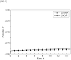
FIG. 2 is a graph showing the open circuit voltage (OCV) characteristics of a hydrogen evolution electrode at hold-off condition according to an embodiment of the present disclosure; -
FIG. 3 includes scanning electron microscope (SEM) images and energy dispersive X-ray spectroscope (EDS) images for analyzing the composition of a hydrogen evolution electrode according to an embodiment of the present disclosure; -
FIGS. 4A ,4B , and4C are graphs showing the results of analyzing the performance of a hydrogen-evolution electrode according to an embodiment of the present disclosure; -
FIGS. 5A and5C include graphs showing the results of evaluating and analyzing the durability of a hydrogen-evolution electrode during repetitive on/off cycles according to a comparative example of the present disclosure; -
FIGS. 5B and5D include graphs showing the results of electrochemical impedance analysis for the durability of a hydrogen-evolution electrode before and after repetitive on/off cycles according to an embodiment of the present disclosure; -
FIG. 6A is a graph showing the results of analyzing the performance of a hydrogen-evolution electrode according to an embodiment of the present disclosure; and -
FIG. 6B is a graph showing the results of X-ray diffraction analysis for analyzing the performance of a hydrogen-evolution electrode according to an embodiment of the present disclosure. - Hereinafter, the present disclosure will be described in detail. The terms used in the present specification are used to explain a specific exemplary embodiment and not to limit the present inventive concept. In the present specification, the expression of singularity includes the expression of plurality unless clearly specified otherwise in context.
- A hydrogen-generating electrode according to one embodiment of the present disclosure includes a phosphide-based metal catalyst layer formed on a conductive base material. In this case, the catalyst layer includes a transition metal and phosphorus (P). The catalyst layer is formed of an amorphous alloy.
- The catalyst layer may further include a sacrificial metal having lower standard reduction potential than that of the transition metal. More specifically, the catalyst layer may include a transition metal, phosphorus (P), and a sacrificial metal having lower standard reduction potential than that of the transition metal.
- The phosphide-based metal may be an alloy composed of phosphorus (P) and a metal element.
- The transition metal may be a metal (active metal species) that exhibits activity in hydrogen generation reaction.
- Metals having lower standard reduction potential than that of the sacrificial metal may be used as the anode sacrificial material of a hydrogen-generating electrode catalyst, and the sacrificial metal may be a metal that does not have corrosion resistance against strong bases.
- The conductive base material may be nickel (Ni), stainless steel 316L, or copper (Cu).
- The transition metal may be cobalt (Co), iron (Fe), or nickel (Ni).
- The sacrificial metal may be chromium (Cr) or manganese (Mn). The sacrificial metal represented by chromium (Cr) or manganese (Mn) has lower standard reduction potential than that of the transition metal including cobalt (Co), iron (Fe), or nickel (Ni), and does not have corrosion resistance against strong bases. Accordingly, an amorphous alloy composed of chromium (Cr) or manganese (Mn), the transition metal such as cobalt (Co), iron (Fe), or nickel (Ni), and phosphorus (P) may be used the sacrificial anode material of a hydrogen-generating electrode catalyst. In this case, the sacrificial metal functions as the sacrificial anode material, does not inhibit the activity of an active metal (transition metal) for hydrogen generation reaction, and is oxidized instead of the active metal when reverse current is generated, so that the activity of a cathode is maintained. Thus, even when the sacrificial anode material (sacrificial metal) is oxidized to be converted into a hydroxide when reverse current is generated, a metal (transition metal) having activity for hydrogen generation reaction is present. Accordingly, the hydrogen generation efficiency of the electrode may be maintained at a high level. This will be described in more detail as follows.
- When reverse current is generated, when only an active metal (transition metal) (M = Co, Fe, or Ni) is present, as shown in
Equation 1 below, the active metal may be oxidized to be converted into a hydroxide, thereby losing the activity of the transition metal for hydrogen generation reaction.
Equation 1. M + OH- → M(OH)2 + 2e-
- On the contrary, when reverse current is generated, when both an active metal (transition metal) (M = Co, Fe or Ni) and a sacrificial anode material (sacrificial metal) (MA = Cr or Mn) are present, as shown in
Equation 2 below, the sacrificial metal having low standard reduction potential is oxidized to be converted into a hydroxide, thus maintaining the activity of the transition metal for hydrogen generation reaction.
Equation 2.
1) MA + OH- → MA(OH)2 + 2e-
2) M - The catalyst layer may include 80 to 90 wt% of the transition metal, 5 to 10 wt% of the sacrificial metal, and 5 to 10 wt% of the phosphorus (P).
- In addition, a method of manufacturing a hydrogen-generating electrode according to one embodiment of the present disclosure includes a step of preparing a catalyst solution including a transition metal solution, a phosphide solution, and a sacrificial metal solution having lower standard reduction potential than that of the transition metal; and a step of forming a catalyst layer on a conductive base material using the catalyst solution.
- The transition metal may be cobalt (Co), iron (Fe), or nickel (Ni).
- The sacrificial metal may be chromium (Cr) or manganese (Mn).
- The conductive base material may be nickel (Ni), stainless steel 316L, or copper (Cu).
- The step of forming the catalyst layer may be performed through electroplating, electroless plating, hydrothermal synthesis, or chemical bath deposition.
- The step of forming the catalyst layer may be performed through electroplating. When the step of forming the catalyst layer is performed through electroplating, the catalyst solution may be used as a plating solution, the ratio of the transition metal ion to phosphite in the catalyst solution may be 0.01 to 0.5, the applied current density may be 1 to 120 mA/cm2, and electroplating may be performed at a temperature of 30 to 50 °C.
- The conductive base material may be stainless steel 316L, and nickel (Ni) strike plating may be performed on the surface of the stainless steel 316L. By performing nickel strike plating, the bonding strength of the catalyst layer formed on stainless steel 316L, which is the conductive base material, may be improved.
- Hereinafter, the present disclosure will be described in more detail through examples. These examples are intended to describe the present disclosure more specifically, but the scope of the present disclosure is not limited by these examples.
- The surface of a nickel (Ni) base material was electroplated with CoP to manufacture a CoP electrode.
- The Ni base material was sequentially pre-treated with 30 wt% of NaOH and 20 wt% of HCl before plating to remove impurities and oxide films present on the surface of the Ni base material.
- A plating solution was prepared by adding 1.2 M sodium hypophosphite monohydrate (NaH2PO2·H2O, Sigma-Aldrich) as a phosphorus (P) source and 0.6 M cobalt (II) chloride hexahydrate (CoCl2·6H2O, JUNSEI) as a cobalt (Co) source to distilled water (DI water).
- Ni was used as a counter electrode, a plated surface area was 1.77 cm2, and plating was performed at room temperature for 450 seconds. When plating, the ratio of [Co2+]/[H2PO2 -] in the plating solution was 0.5, the applied current density was 120 mA/cm2, and temperature was 30 °C.
- After plating, the electrode was washed with distilled water, followed by drying for more than 1 hour under vacuum.
- In this case, in a catalyst layer formed on the final electrode, the weight ratio of P was 4 wt% and the weight ratio of Co was 96 wt%. Accordingly, in the catalyst layer formed on the final electrode, the atomic ratio of P was 6 at% and the atomic ratio of Co was 94 at% (Co0.94P0.6).
- Nickel strike plating was performed on the surface of a stainless steel (SUS) 316L base material, and then electroplating was performed on nickel plated on the surface of the stainless steel 316L base material in the same manner as in Example 1 to manufacture a CoP electrode. In this case, before plating, the stainless steel 316L base material was sequentially pre-treated with 30 wt% of NaOH and 20 wt% of HCl to remove impurities and oxide films present on the surface of the stainless steel 316L base material.
- In this case, in a catalyst layer formed on the final electrode, the weight ratio of P was 4 wt% and the weight ratio of Co was 96 wt%. Accordingly, in the catalyst layer formed on the final electrode, the atomic ratio of P was 6 at% and the atomic ratio of Co was 94 at% (Co0.94P0.6).
- The surface of a nickel (Ni) base material was electroplated with CoMnP to manufacture a CoMnP electrode.
- Before plating, the Ni base material was sequentially pre-treated with 30 wt% of NaOH and 20 wt% of HCl to remove impurities and oxide films present on the surface of the Ni base material.
- A plating solution was prepared by adding, based on 1 L of the plating solution, 1.2 mol (1.2 M) sodium hypophosphite monohydrate (NaH2PO2·H2O, Sigma-Aldrich) as a phosphorus (P) source, 0.6 mol (0.6 M) cobalt (II) chloride hexahydrate (CoCl2·6H2O, JUNSEI) as a cobalt (Co) source, and 0.06 mol (0.06 M) manganese chloride tetrahydrate (MnCl2·4H2O, JUNSEI) to distilled water (DI water) as a solvent.
- Ni was used as a counter electrode, a plated surface area was 1.77 cm2, and plating was performed at room temperature for 450 seconds. When plating, the ratio of [Co2+]/[H2PO2 -] in the plating solution was 0.5, the applied current density was 120 mA/cm2, and temperature was 30 °C.
- After plating, the electrode was washed with distilled water, followed by drying for more than 1 hour under vacuum.
- In this case, in a catalyst layer formed on the final electrode, the weight ratio of Mn was 5 wt%, the weight ratio of P was 5 wt%, and the weight ratio of Co was 90 wt%. Accordingly, in the catalyst layer formed on the final electrode, the atomic ratio of Mn was 5 at%, the atomic ratio of P was 9 at%, and the atomic ratio of Co was 86 at% (Co0.86Mn0.05P0.09).
- Nickel strike plating was performed on the surface of a stainless steel (SUS) 316L base material, and then electroplating was performed on nickel plated on the stainless steel 316L base material in the same manner as in Example 3 to manufacture a CoMnP electrode. In this case, before plating, the stainless steel 316L base material was sequentially pre-treated with 30 wt% of NaOH and 20 wt% of HCl to remove impurities and oxide films present on the surface of the stainless steel 316L base material.
- In this case, in a catalyst layer formed on the final electrode, the weight ratio of Mn was 5 wt%, the weight ratio of P was 5 wt%, and the weight ratio of Co was 90 wt%. Accordingly, in the catalyst layer formed on the final electrode, the atomic ratio of Mn was 5 at%, the atomic ratio of P was 9 at%, and the atomic ratio of Co was 86 at% (Co0.86Mn0.05P0.09). Before plating, the stainless steel 316L base material was sequentially pre-treated with 30 wt% of NaOH and 20 wt% of HCl to remove impurities and oxide films present on the surface of the base material.
- Nickel strike plating was performed on the surface of a stainless steel (SUS) 316L base material, and then electroplating was performed on nickel plated on the stainless steel 316L base material as in the same manner as in in Example 3 to prepare a CoCrP electrode, except that CrCl2 was used instead of MnCl2. In this case, before plating, the stainless steel 316L base material was sequentially pre-treated with 30 wt% of NaOH and 20 wt% of HCl to remove impurities and oxide films present on the surface of the stainless steel 316L base material.
- In this case, in a catalyst layer formed on the final electrode, the weight ratio of Mn was 5 wt%, the weight ratio of P was 5 wt%, and the weight ratio of Co was 90 wt%. Accordingly, in the catalyst layer formed on the final electrode, the atomic ratio of Mn was 5 at%, the atomic ratio of P was 9 at%, and the atomic ratio of Co was 86 at% (Co0.86Mn0.05P0.09).
- The manufacture conditions of Examples 1 to 5 and comparative examples are summarized in Table 1 below.
[Table 1] Electrode base material Plating composition Plating solution Example 1 Ni CoP NaH2PO2·H2O + CoCl2·6H2O Example 2 Stainless steel 316L + Ni strike plating CoP NaH2PO2·H2O + CoCl2·6H2O Example 3 Ni CoMnP NaH2PO2·H2O + CoCl2·6H2O + MnCl2·4H2O Example 4 Stainless steel 316L + Ni strike plating CoMnP NaH2PO2·H2O + CoCl2·6H2O + MnCl2·4H2O Example 5 Stainless steel 316L + Ni strike plating CoCrP NaH2PO2·H2O + CoCl2·6H2O + CrCl2·4H2O - The hydrogen generation open circuit voltage (OCV) characteristics and the XRD analysis results of the CoP electrode manufactured in Example 1 are shown in
FIGS. 1A and1B , and the open circuit voltage (OCV) characteristics and the XRD analysis results of a CoP electrode having a crystal structure as a comparative example are shown inFIGS. 1C and1D . -
FIGS. 1A and1C show open circuit voltage (OCV) characteristics,FIGS. 1B and1D show XRD analysis results. - Referring to
FIGS. 1A and1B , in the case of the amorphous CoP electrode manufactured in Example 1, potential rise (oxidation reaction of Co catalyst) width over time is relatively small, and potential rise is slow (FIG. 1A ). In addition, no crystalline peak is observed. Thus, it can be seen that the CoP electrode has an amorphous structure (FIG. 1B ). - Referring to
FIGS. 1C and1D , in the case of the CoP electrode having a crystalline structure as a comparative example, potential change over time is significant, showing rapid potential rise for a short time (about 5 hours) (FIG. 1C ), peaks are observed at (100), (101), (110), and (200), and the hexagonal close packed (HCP) crystal structure of Co is shown (FIG. 1D ). - The hydrogen generation open circuit voltage (OCV) characteristics of the CoMnP electrode manufactured in Example 3 and the CoCrP electrode manufactured in Example 5 were analyzed, and the results are shown in
FIG. 2 . - Referring to
FIG. 2 , it can be confirmed that both the CoMnP electrode ('CoMnP') of Example 3 and the CoCrP electrode ('CoCrP') of Example 5 exhibit stable voltage characteristics. - A scanning electron microscope image for analyzing the composition of a CoMnP catalyst in the CoMnP electrode manufactured in Example 3 and a scanning electron microscope (SEM)-energy dispersive X-ray spectroscope (EDS) image for Mn, P, and Co were obtained, and the obtained images are shown in
FIG. 3 ((a): SEM image showing surface of CoMnP catalyst, (b): EDS image of Mn, (c): EDS image of P, and (d): EDS image of Co). - Referring to
FIG. 3 , it can be confirmed that Co, Mn, and P are evenly distributed on a surface. - Change in the performance (change in activity in hydrogen generation reaction (HER)) of the CoP electrode manufactured in Example 1 and the CoMnP electrode manufactured in Example 3 before and after stopping water electrolysis operation was analyzed using linear sweep voltammetry (LSV).
- Performance change was measured using a three electrode system. In this case, the CoP electrode manufactured in Example 1 and the CoMnP electrode manufactured in Example 3 were used as working electrodes, Hg/HgO was used as a reference electrode, a platinum (Pt) mesh was used as a counter electrode, and performance change was measured at 25 °C in a 1M KOH electrolyte at a scan rate of 1 mV/s.
- The measured results are shown in
FIG. 4A . InFIG. 4A , performance change (blue line) for hydrogen generation reaction when the surface of a metal (nickel) base material is plated only with Mn is shown as an additional control group. - In measurement of performance change, for the CoP electrode (Example 1) and the CoMnP electrode (Example 3), during water electrolysis operation ('initial' in
FIG. 4A ) and5 hours after operation is stopped (power off) ('after shut-down' inFIG. 4A ), performance change is expressed as current density (A/cm2) according to IR corrected voltages. - Referring to
FIG. 4A , when, compared to a theoretical voltage value (0.95 V (vs. Hg/HgO)) for hydrogen generation reaction, applied voltage (i.e., overvoltage) is small and a current value is large, this case exhibits good activity. Although activity for hydrogen generation reaction when a metal base material is plated only with Mn (light blue line) is small, during water electrolysis operation (initial), when the CoMnP electrode according to Example 3 is configured, there is no difference in activity (water electrolysis performance) compared to the CoP electrode (Example 1). In the case of the CoMnP electrode (Example 3), when measuring performance again after maintaining a condition of 5-hour operation stop (after shut-down), there is no activity change (performance deterioration) for hydrogen generation reaction. However, in the case of the CoP electrode (Example 1), when measuring performance again after maintaining a condition of 5-hour operation stop (after shut-down), overvoltage is observed, indicating deterioration in performance. - For the CoP electrode (CoP electrode/SUS) manufactured in Example 2 and the CoMnP electrode (CoMnP electrode/SUS) manufactured in Example 4, performance change was measured in the same manner as in the CoP electrode of Example 1 and the CoMnP electrode of Example 3, and the results are shown in
FIG. 4B . - Referring to
FIG. 4B , the results ofFIG. 4B are similar to those shown inFIG. 4A . More specifically, during water electrolysis operation (initial), the CoMnP electrode/SUS according to Example 4 shows no difference in activity (water electrolysis performance) compared to the CoP electrode/SUS (Example 2). In the case of the CoMnP electrode/SUS (Example 4), when measuring performance again after maintaining a condition of 5-hour operation stop (after shut-down), there is no activity change (performance deterioration) for hydrogen generation reaction. However, in the case of the CoP electrode/SUS (Example 2), when measuring performance again after maintaining a condition of 5-hour operation stop (after shut-down), overvoltage is observed, indicating deterioration in performance. - For the CoCrP electrode (CoCrP electrode/SUS) manufactured in Example 5, performance change was measured in the same manner as in the CoMnP electrode of Example 3, and the results are shown in
FIG. 4C . - Referring to
FIG. 4C , the results ofFIG. 4C are similar to those shown inFIG. 4A . More specifically, during water electrolysis operation (initial), when measuring performance again after maintaining a condition of 5-hour operation stop (after shut-down), the CoCrP electrode (CoCrP electrode/SUS) according to Example 5 exhibits little change in activity (insignificant degradation in performance) for hydrogen generation reaction. - The CoP electrode manufactured in Example 1 and the CoMnP electrode manufactured in Example 3 were used as working electrodes, Hg/HgO was used as a reference electrode, a platinum (Pt) mesh was used as a counter electrode, and durability according to operation ('on' or 'Before shut-down')/stop ('off' or 'After shut-down') at 25 °C in a 1 M KOH electrolyte was evaluated. The obtained results are shown in
FIG. 5A (Example 1),FIG. 5B (Example 1),FIG. 5C (Example 3) andFIG. 5D (Example 3). - In
FIGS. 5A ,5B ,5C and5D , when durability was evaluated, change in open circuit voltage (OCV) was measured while repeating a process of maintaining at a current density of -200 mA/cm2 (on) for 1 hour and maintaining at 0 mA/cm2 (off) for 1 hour. - Referring to
FIG. 5A , in the case of Example 1 (CoP electrode), when maintaining at 200 mA/cm2 ('on' inFIG. 5A ) during operation, voltage continuously decreased from -1.05 V to -1.45 V (overvoltage rise = deterioration). When maintaining at 0 mA/cm2 ('off' inFIG. 5A ) corresponding to operation stop, voltage continuously increased from -0.95 V to -0.85 V (= deterioration). Referring toFIG. 5B , as a result of impedance analysis, in comparison with operation ('Before shut-down' inFIG. 5B ) before durability evaluation, after operation is stopped after durability evaluation('After shut-down' inFIG. 5B ), the size of the semicircle, which indicates deterioration in performance of the electrode, greatly increases. - However, referring to
FIG. 5C , in the case of Example 3 (CoMnP electrode), when maintaining at 200 mA/cm2 ('on' inFIG. 5C ) during operation, voltage is -1.3 V. When maintaining at 0 mA/cm2 ('off' inFIG. 5C ) corresponding to operation stop, measured voltage is maintained at -0.90 V (performance maintenance). Referring toFIG. 5D , as a result of impedance analysis, in comparison with operation before durability evaluation ('Before shut-down' inFIG. 5D ), after operation is stopped after durability evaluation ('After shut-down' inFIG. 5D ), the size of the semicircle, which indicates deterioration in performance of the electrode, does not increase significantly. - Experimental Example 6 was performed in the same manner as in Experimental Example 4. For the CoMnP electrode (Example 3), durability was evaluated using linear sweep voltammetry (LSV) immediately after hydrogen generation reaction (during operation) (After HER), 5 hours after stopping operation (After 5 h shut-down), and 15 hours after stopping operation (After 15 h shut-down). For each condition (immediately after hydrogen generation reaction (during operation) (After HER), 5 hours after stopping operation (After 5 h shut-down), and 15 hours after stopping operation (After 15 h shut-down)), X-ray diffraction (XRD) analysis results are shown in
FIGS. 6A and6B . As time maintained at 0 mA/cm2 (stopping operation (shut-down)) increased, activity for hydrogen generation reaction decreased. 5 hours after stopping operation ('After 5 h shut-down' inFIG. 6A ), no performance change was observed in the CoMnP electrode. 5 hours after stopping operation ('After 5 h shut-down' inFIG. 6B ), the Mn(OH)2 peak was observed at the surface of the CoMnP electrode. 15 hours after stopping operation ('After 15 h shut-down' inFIG. 6A ), the performance of the CoMnP electrode deteriorated. As a result of XRD analysis ('After 15 h shut-down' inFIG. 6B ), the Mn(OH)2 peak and the Co(OH)2 peak were observed at the surface of the CoMnP electrode. Based on these results, it was confirmed that the Co(OH)2 peak was a major factor indicating performance degradation. In addition, it was confirmed that, by using Mn as a sacrificial anode material, before Co was oxidized, Mn was oxidized to be converted into Mn(OH)2, thereby protecting Co, which was an active material (FIG. 6B ). - In addition, referring to
FIG. 6B , in the case of the CoMnP electrode (Example 3), during operation (After HER) after hydrogen generation reaction, 5 hours after stopping operation (After 5 h shut-down), and 15 hours after stopping operation (After 15 h shut-down), no clear peak is observed in X-ray diffraction analysis, indicating that the CoMnP electrode according to Example 3 has an amorphous phase. - For the electrodes manufactured in Example 3 (CoMnP electrode), Example 4 (CoMnP electrode), and Example 5 (CoCrP electrode), five samples per each electrode were prepared, and an accelerated life test was performed at 80 °C in a 30 wt% KOH electrolyte in a repeated on/off cycle condition wherein operation was performed at a current density of 400 mA/cm2 (on) for 1 hour and then operation was performed at 0 mA/cm2 (off or shut-down) for 30 minutes.
- In the accelerated life test, performance for hydrogen generation reaction was periodically evaluated using linear sweep voltammetry. Cathode potential was detected at 400 mA/cm2 and defined as the number of cycles (average deactivation times) required for potential to increase by 100 mV. The number of cycles (average deactivation times) of the five samples of Example 3 (CoMnP electrode) was 1,112 times, the number of cycles (average deactivation times) of the five samples of Example 4 (CoMnP electrode) was 1,060 times, and the number of cycles (average deactivation times) of the five samples of Example 5 (CoCrP electrode) was 1,530 times.
- According to the present disclosure, hydrogen generation efficiency comparable to that of a precious metal (or noble metal) can be secured using a transition metal and a non-precious metal.
- In addition, by using a proper sacrificial metal as a sacrificial anode material, operation durability associated with operation (on)/stop (off) for hydrogen generation reaction of an active metal (transition metal) can be secured. Thereby, when a water electrolysis device is connected to regenerative power, stable operation of load fluctuation input can be secured.
- Meanwhile, embodiments of the present disclosure disclosed in the present specification and drawings are only provided to aid in understanding of the present disclosure and the present disclosure is not limited to the embodiments. It will be apparent to those skilled in the art that various modifications can be made to the above-described exemplary embodiments of the present disclosure without departing from the spirit and scope of the invention.
- Certain parts of the invention have been described in detail. Those skilled in the art will clearly understand that this specific description is only for preferred embodiments, and the scope of the present disclosure is not limited by these embodiments.
Claims (10)
- A hydrogen-generating electrode, comprising:a phosphide-based metal catalyst layer formed on a conductive base material,wherein the catalyst layer is formed of an amorphous alloy comprising a transition metal and a sacrificial metal having lower standard reduction potential than that of the transition metal.
- The hydrogen-generating electrode according to claim 1, wherein the conductive base material is nickel (Ni), stainless steel 316L, or copper (Cu).
- The hydrogen-generating electrode according to claim 1 or 2, wherein the transition metal is cobalt (Co).
- The hydrogen-generating electrode according to one of claims 1 to 3, wherein the sacrificial metal is chromium (Cr) or manganese (Mn).
- The hydrogen-generating electrode according to one of claims 1 to 4, wherein the catalyst layer comprises 80 to 90 wt% of the transition metal, 5 to 10 wt% of the sacrificial metal, and 5 to 10 wt% of phosphorus (P).
- A method of manufacturing a hydrogen-generating electrode, comprising:preparing a catalyst solution comprising a transition metal solution and a sacrificial metal solution having lower standard reduction potential than that of the transition metal; andforming a catalyst layer on a conductive base material using the catalyst solution.
- The method according to claim 6, wherein the transition metal is cobalt (Co).
- The method according to claim 6 or 7, wherein the sacrificial metal is chromium (Cr) or manganese (Mn).
- The method according to one of claims 6 to 8, wherein the conductive base material is nickel (Ni), stainless steel 316L, or copper (Cu).
- The method according to claim 9, wherein the conductive base material is stainless steel 316L, and nickel (Ni) strike plating is performed on a surface of the stainless steel 316L.
Applications Claiming Priority (1)
| Application Number | Priority Date | Filing Date | Title |
|---|---|---|---|
| KR1020200025171A KR20210109926A (en) | 2020-02-28 | 2020-02-28 | Robust hydrogen generating electrode under dynamic operation and methode for manufacturing thereof |
Publications (1)
| Publication Number | Publication Date |
|---|---|
| EP3872234A1 true EP3872234A1 (en) | 2021-09-01 |
Family
ID=72665138
Family Applications (1)
| Application Number | Title | Priority Date | Filing Date |
|---|---|---|---|
| EP20198733.6A Withdrawn EP3872234A1 (en) | 2020-02-28 | 2020-09-28 | Hydrogen-generating electrode responsive to load fluctuation and method of manufacturing the same |
Country Status (2)
| Country | Link |
|---|---|
| EP (1) | EP3872234A1 (en) |
| KR (2) | KR20210109926A (en) |
Cited By (2)
| Publication number | Priority date | Publication date | Assignee | Title |
|---|---|---|---|---|
| CN114618539A (en) * | 2022-02-23 | 2022-06-14 | 燕山大学 | A kind of hierarchical structure sodium borohydride hydrogen production catalyst and its preparation method and application |
| CN116043265A (en) * | 2023-01-03 | 2023-05-02 | 辽宁工程技术大学 | Hierarchical NiO x Preparation method and application of/CoP self-supporting electrode |
Citations (8)
| Publication number | Priority date | Publication date | Assignee | Title |
|---|---|---|---|---|
| US4238311A (en) | 1978-02-20 | 1980-12-09 | Chlorine Engineers Corporation, Ltd. | Cathode for use in electrolysis and method for the production thereof |
| US4465580A (en) | 1978-02-20 | 1984-08-14 | Chlorine Engineers Corp. Ltd. | Cathode for use in electrolysis |
| JPH0138741B2 (en) | 1983-12-16 | 1989-08-16 | Beloit Corp | |
| KR20070013409A (en) | 2005-07-26 | 2007-01-31 | 김봉석 | Gas-liquid Separation Unit of Refrigeration System |
| JP2011511158A (en) | 2008-01-31 | 2011-04-07 | カサーレ ケミカルズ エス.エー. | High performance cathode for water electrolysis equipment |
| JP5876811B2 (en) | 2012-10-31 | 2016-03-02 | ティッセンクルップ・ウーデ・クロリンエンジニアズ株式会社 | Method for preventing reverse current of ion exchange membrane electrolytic cell |
| KR101614639B1 (en) | 2012-03-19 | 2016-04-21 | 아사히 가세이 케미칼즈 가부시키가이샤 | Electrolysis cell and electrolysis tank |
| WO2018175594A1 (en) * | 2017-03-21 | 2018-09-27 | William Marsh Rice University | Thin films of transition metal phosphides coated on a semiconductor core from organometallic precursors for oxygen evolution and hydrogen evolution catalysis |
Family Cites Families (6)
| Publication number | Priority date | Publication date | Assignee | Title |
|---|---|---|---|---|
| JPS57172205A (en) * | 1981-04-16 | 1982-10-23 | Seiko Instr & Electronics Ltd | Head device for measuring plating thickness by x rays |
| JPS6012829U (en) | 1983-06-30 | 1985-01-28 | パイオニア株式会社 | Crosstalk removal device for recorded information playback device |
| US20100101955A1 (en) * | 2008-06-18 | 2010-04-29 | Massachusetts Institute Of Technology | Catalytic materials, electrodes, and systems for water electrolysis and other electrochemical techniques |
| JP6438741B2 (en) | 2014-11-07 | 2018-12-19 | 旭化成株式会社 | Electrical insulation method for electrolysis system |
| WO2018142461A1 (en) * | 2017-01-31 | 2018-08-09 | 国立大学法人弘前大学 | Method for manufacturing electrode and method for producing hydrogen |
| KR20190017284A (en) * | 2017-08-10 | 2019-02-20 | 한국과학기술원 | SYNTHESIS METHOD OF Co-P FOAM BY CATHODIC ELECTRODEPOSITION METHOD |
-
2020
- 2020-02-28 KR KR1020200025171A patent/KR20210109926A/en not_active Ceased
- 2020-09-28 EP EP20198733.6A patent/EP3872234A1/en not_active Withdrawn
-
2022
- 2022-02-22 KR KR1020220022961A patent/KR102473836B1/en active Active
Patent Citations (8)
| Publication number | Priority date | Publication date | Assignee | Title |
|---|---|---|---|---|
| US4238311A (en) | 1978-02-20 | 1980-12-09 | Chlorine Engineers Corporation, Ltd. | Cathode for use in electrolysis and method for the production thereof |
| US4465580A (en) | 1978-02-20 | 1984-08-14 | Chlorine Engineers Corp. Ltd. | Cathode for use in electrolysis |
| JPH0138741B2 (en) | 1983-12-16 | 1989-08-16 | Beloit Corp | |
| KR20070013409A (en) | 2005-07-26 | 2007-01-31 | 김봉석 | Gas-liquid Separation Unit of Refrigeration System |
| JP2011511158A (en) | 2008-01-31 | 2011-04-07 | カサーレ ケミカルズ エス.エー. | High performance cathode for water electrolysis equipment |
| KR101614639B1 (en) | 2012-03-19 | 2016-04-21 | 아사히 가세이 케미칼즈 가부시키가이샤 | Electrolysis cell and electrolysis tank |
| JP5876811B2 (en) | 2012-10-31 | 2016-03-02 | ティッセンクルップ・ウーデ・クロリンエンジニアズ株式会社 | Method for preventing reverse current of ion exchange membrane electrolytic cell |
| WO2018175594A1 (en) * | 2017-03-21 | 2018-09-27 | William Marsh Rice University | Thin films of transition metal phosphides coated on a semiconductor core from organometallic precursors for oxygen evolution and hydrogen evolution catalysis |
Non-Patent Citations (2)
| Title |
|---|
| SAFIZADEH FARIBA ET AL: "Electrocatalysis developments for hydrogen evolution reaction in alkaline solutions - A Re", INTERNATIONAL JOURNAL OF HYDROGEN ENERGY, ELSEVIER SCIENCE PUBLISHERS B.V., BARKING, GB, vol. 40, no. 1, 20 November 2014 (2014-11-20), pages 256 - 274, XP029114511, ISSN: 0360-3199, DOI: 10.1016/J.IJHYDENE.2014.10.109 * |
| SEQUEIRA C A C ET AL: "Electrocatalytic activity of simple and modified FeP electrodeposits for hydrogen evolution from alkaline media", ENERGY, ELSEVIER, AMSTERDAM, NL, vol. 36, no. 2, 15 December 2010 (2010-12-15), pages 847 - 853, XP028140046, ISSN: 0360-5442, [retrieved on 20101221], DOI: 10.1016/J.ENERGY.2010.12.030 * |
Cited By (2)
| Publication number | Priority date | Publication date | Assignee | Title |
|---|---|---|---|---|
| CN114618539A (en) * | 2022-02-23 | 2022-06-14 | 燕山大学 | A kind of hierarchical structure sodium borohydride hydrogen production catalyst and its preparation method and application |
| CN116043265A (en) * | 2023-01-03 | 2023-05-02 | 辽宁工程技术大学 | Hierarchical NiO x Preparation method and application of/CoP self-supporting electrode |
Also Published As
| Publication number | Publication date |
|---|---|
| KR20210109926A (en) | 2021-09-07 |
| KR102473836B9 (en) | 2024-10-16 |
| KR102473836B1 (en) | 2022-12-06 |
| KR20220027129A (en) | 2022-03-07 |
Similar Documents
| Publication | Publication Date | Title |
|---|---|---|
| Wang et al. | Self-supported NiMo-based nanowire arrays as bifunctional electrocatalysts for full water splitting | |
| Vidales et al. | Nickel-cobalt-oxide cathodes for hydrogen production by water electrolysis in acidic and alkaline media | |
| GolrokháAmin | CoNi 2 Se 4 as an efficient bifunctional electrocatalyst for overall water splitting | |
| EP3511443B1 (en) | Method for producing anode for alkaline water electrolysis and anode for alkaline water electolysis | |
| EP3170921A1 (en) | Electrode material | |
| Ha et al. | Industrial-scale efficient alkaline water electrolysis achieved with sputtered NiFeV-oxide thin film electrodes for green hydrogen production | |
| JP2023523614A (en) | Anion-exchange membrane electrolyzer with platinum-group metal-free self-supporting oxygen-evolving electrodes | |
| KR102438940B1 (en) | Water decomposition electrochemical catalyst comprising cobalt nanostructures doped with molybdenum and phosphorus and method for preparing the same | |
| Rosalbino et al. | Electrocatalytic activity of crystalline Ni–Co–M (M= Cr, Mn, Cu) alloys on the oxygen evolution reaction in an alkaline environment | |
| US20190055657A1 (en) | Oxygen evolution electrocatalysts with carbon coated cobalt (ii, iii) oxide layers | |
| Vidales et al. | The influence of addition of iridium-oxide to nickel-molybdenum-oxide cathodes on the electrocatalytic activity towards hydrogen evolution in acidic medium and on the cathode deactivation resistance | |
| CN105780050B (en) | A kind of preparation method for decomposing the doping phosphoric acid group Ni-Fe hydroxide nano film catalysts of water | |
| US7704909B2 (en) | Electrode for hydrogen generation and process for preparation thereof | |
| Muntean et al. | Synthesis and characterisation of platinum–cobalt–manganese ternary alloy catalysts supported on carbon nanofibers: An alternative catalyst for hydrogen evolution reaction | |
| EP4206361A1 (en) | Anode for alkaline water electrolysis | |
| Madram et al. | Preparation of Ni–P–La alloy as a novel electrocatalysts for hydrogen evolution reaction | |
| KR102473836B1 (en) | Robust hydrogen generating electrode under dynamic operation | |
| Park et al. | Synergistic enhancement of surface-doped Mn and Cu-mediated hierarchical reconstruction in Co–Ni–Cu–Mn electrocatalyst for hydrogen production in proton exchange membrane water electrolyzer | |
| Ge et al. | Low-cost and multi-level structured NiFeMn alloy@ NiFeMn oxyhydroxide electrocatalysts for highly efficient overall water splitting | |
| US20250116017A1 (en) | Mixed metal iridium ruthenium palladium electrocatalysts | |
| JP2023543550A (en) | Electrodes for gas generation in electrolytic processes | |
| KR20260036596A (en) | Electrode for electrochemical evolution of hydrogen | |
| EP3465808B1 (en) | Mixed metal oxide compounds and electrocatalytic compositions, devices and processes using the same | |
| Vasić et al. | Electrocatalysis of hydrogen and oxygen electrode reactions in alkaline media by Rh-modified polycrystalline Ni electrode | |
| Bodnarova et al. | Improved catalytic activity of MoxNiyAlz thin films as electrocatalyst for hydrogen evolution reaction in alkaline media |
Legal Events
| Date | Code | Title | Description |
|---|---|---|---|
| PUAI | Public reference made under article 153(3) epc to a published international application that has entered the european phase |
Free format text: ORIGINAL CODE: 0009012 |
|
| STAA | Information on the status of an ep patent application or granted ep patent |
Free format text: STATUS: REQUEST FOR EXAMINATION WAS MADE |
|
| 17P | Request for examination filed |
Effective date: 20200928 |
|
| AK | Designated contracting states |
Kind code of ref document: A1 Designated state(s): AL AT BE BG CH CY CZ DE DK EE ES FI FR GB GR HR HU IE IS IT LI LT LU LV MC MK MT NL NO PL PT RO RS SE SI SK SM TR |
|
| RBV | Designated contracting states (corrected) |
Designated state(s): AL AT BE BG CH CY CZ DE DK EE ES FI FR GB GR HR HU IE IS IT LI LT LU LV MC MK MT NL NO PL PT RO RS SE SI SK SM TR |
|
| STAA | Information on the status of an ep patent application or granted ep patent |
Free format text: STATUS: EXAMINATION IS IN PROGRESS |
|
| 17Q | First examination report despatched |
Effective date: 20221201 |
|
| GRAP | Despatch of communication of intention to grant a patent |
Free format text: ORIGINAL CODE: EPIDOSNIGR1 |
|
| STAA | Information on the status of an ep patent application or granted ep patent |
Free format text: STATUS: GRANT OF PATENT IS INTENDED |
|
| INTG | Intention to grant announced |
Effective date: 20250207 |
|
| STAA | Information on the status of an ep patent application or granted ep patent |
Free format text: STATUS: THE APPLICATION IS DEEMED TO BE WITHDRAWN |
|
| 18D | Application deemed to be withdrawn |
Effective date: 20250611 |