EP3872026A1 - A support arrangement and a crane arrangement provided therewith - Google Patents
A support arrangement and a crane arrangement provided therewith Download PDFInfo
- Publication number
- EP3872026A1 EP3872026A1 EP20160075.6A EP20160075A EP3872026A1 EP 3872026 A1 EP3872026 A1 EP 3872026A1 EP 20160075 A EP20160075 A EP 20160075A EP 3872026 A1 EP3872026 A1 EP 3872026A1
- Authority
- EP
- European Patent Office
- Prior art keywords
- hollow beam
- hoses
- hose connector
- stabilizer leg
- arrangement
- Prior art date
- Legal status (The legal status is an assumption and is not a legal conclusion. Google has not performed a legal analysis and makes no representation as to the accuracy of the status listed.)
- Withdrawn
Links
Images



Classifications
-
- B—PERFORMING OPERATIONS; TRANSPORTING
- B66—HOISTING; LIFTING; HAULING
- B66C—CRANES; LOAD-ENGAGING ELEMENTS OR DEVICES FOR CRANES, CAPSTANS, WINCHES, OR TACKLES
- B66C23/00—Cranes comprising essentially a beam, boom, or triangular structure acting as a cantilever and mounted for translatory of swinging movements in vertical or horizontal planes or a combination of such movements, e.g. jib-cranes, derricks, tower cranes
- B66C23/62—Constructional features or details
- B66C23/72—Counterweights or supports for balancing lifting couples
- B66C23/78—Supports, e.g. outriggers, for mobile cranes
- B66C23/80—Supports, e.g. outriggers, for mobile cranes hydraulically actuated
Definitions
- the present invention relates to a support arrangement for supporting a truck-mounted crane, said arrangement comprising a support structure comprising a telescopically extendable hollow beam, a first stabilizer leg arranged at a first end of the hollow beam, and second stabilizer leg arranged at a second end of the hollow beam, wherein each stabilizer leg comprises a first part and a second part that are displaceable in relation to each other in a longitudinal direction of the stabilizer leg, and wherein there is provided a hydraulic piston-cylinder arrangement in each stabilizer leg, which hydraulic piston-cylinder arrangement is configured to execute said displacement, each stabilizer leg is pivotally connected to the hollow beam around an axis generally parallel with a longitudinal axis of the hollow beam, and, for each stabilizer leg, at least two hoses configured for the supply and return of hydraulic liquid to and from the hydraulic piston-cylinder arrangement of the stabilizer leg, wherein, for each stabilizer leg, said hoses extend inside the hollow beam and are fixedly connected to a first hose connector provided at the hollow beam and a second
- the invention also relates to a crane arrangement provided with such a support arrangement.
- the object of the present invention is achieved by means of a support arrangement for supporting a truck-mounted crane, the arrangement comprising:
- the holder arrangement is configured to prevent a predetermined motion of the hoses in a direction perpendicular to the longitudinal direction of the hollow beam from the region of the second hose connector to a first point at a first predetermined distance from the second hose connector, the movement of the hoses due to twisting which causes the hoses to form curves and bends diverging from their route in the longitudinal direction of the beam is limited within a section defined between said region of the second hose connector and said first point at the first predetermined distance from the second hose connector.
- the predetermined motion of the hoses in said direction perpendicular to the longitudinal direction of the hollow beam can be controlled and undesired motions of the hoses in said direction that may affect their lifetime and functionality negatively can be prevented.
- the stabilizer legs can be pivoted, i.e. rotated while the hoses may be twisted in a controllable manner.
- an element configured to fix the position of the respective hose of each pair of hoses in relation to the longitudinal axis of the hollow beam.
- the first point and the second point are at the same distance from the second hose connector.
- the holder arrangement comprises a tube, inside which the hoses extend.
- the hoses extend along the tube and are enclosed by the tube.
- the element for fixing the positon of the hoses is attached to the tube, preferably to an end of the tube.
- the holder arrangement comprises a plurality of discrete holder elements.
- the second predetermined distance is long enough to enable a twisting of the hoses induced by a pivotation of the stabilizer leg of at least 90°.
- the hoses follow a path along which they are bent to a U-shape and from which U-bend they extend in the longitudinal direction of the hollow beam to the first hose connector.
- the first hose connector is located at a first part of the hollow beam, in relation to which first part the stabilizer leg and the second hose connector is displaceable in the longitudinal direction of the hollow beam as a result of a telescopic motion of a second part of the hollow beam, to which second part the stabilizer leg is pivotally connected.
- the holder arrangement is connected to the second part of the hollow beam.
- a piston-cylinder arrangement configured for a telescopic displacement of a second part of the hollow beam in relation to a first part of the hollow beam is arranged inside the hollow beam, wherein the hoses extend in parallel with and beside the piston-cylinder arrangement.
- the holder arrangement is also configured to house electric cables extending at least partly in parallel with the hoses, thereby preventing a predetermined motion of the electric cables in a direction perpendicular to the longitudinal direction of the hollow beam from the region of the second hose connector to the first point.
- the object is achieved by a crane arrangement comprising a crane which comprises a support arrangement according to any one of the embodiments described above.
- Figs. 1 and 2 show a crane arrangement comprising a crane 1 and a support arrangement 2 according to by which support arrangement 2 the crane 1 is supported.
- a truck on which the crane arrangement may be arranged is also indicated in figs. 1 and 2 .
- the support arrangement 2 comprises a support structure comprising a telescopically extendable hollow beam 3, a first stabilizer leg 4 arranged at a first end of the hollow beam, and a second stabilizer leg 5 arranged at a second end of the hollow beam 3.
- Each stabilizer leg 4, 5 comprises a first part 6, 7 and a second part 8, 9 that are displaceable in relation to each other in a longitudinal direction of the stabilizer leg 4, 5.
- a hydraulic piston-cylinder arrangement 10 in each stabilizer leg 4, 5, which hydraulic piston-cylinder arrangement 10 is configured to execute said displacement.
- Each stabilizer leg 4, 5 is pivotally connected to the hollow beam 3 around an axis generally parallel with a longitudinal axis x of the hollow beam 3.
- hoses 11, 12 configured for the supply and return of hydraulic liquid to and from the hydraulic piston-cylinder arrangement 10 of the stabilizer leg 4, 5.
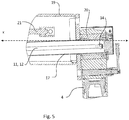
- Figs. 3-5 only one of hoses 11, 12 is actually visible, since they are in alignment with each other.
- Fig. 6 shows both the hoses 11, 12.
- hoses 11, 12 extend inside the hollow beam 3 and are fixedly connected to a first hose connector 13 provided at the hollow beam 3 and a second hose connector 14 provided at an end of the respective stabilizer leg 4, 5 adjacent the hollow beam 3.
- the hoses 11, 12 of the respective stabilizer leg 4, 5 extend from its associated second hose connector 14 in the longitudinal direction of the hollow beam 3.
- the support arrangement 2 comprises a holder arrangement 15 configured to prevent a predetermined motion of the hoses 11, 12 in a direction perpendicular to the longitudinal direction of the hollow beam 3 from the region of the second hose connector 14 to a first point p1 at a first predetermined distance from the second hose connector 14.
- the holder arrangement 15 is also configured to allow internal twisting of the pair of hoses 11, 12 from the region of the second hose connector 14 up to a second point p2 at a second predetermined distance from the second hose connector 14. The twisting of the hoses 11, 12 is the result of a pivotation of the stabilizer leg.
- an element 16 configured to fix the position of the respective hose 11, 12 of each pair of hoses in relation to the longitudinal axis x of the second part 20 of the hollow beam 3.
- the first point p1 and the second point p2 are at the same distance from the second hose connector 14.
- the first point p1 and the second point p2 may however be located at different distances from the second hose connector 14.
- the distance between p2 and the second hose connector 14 may be greater than between p1 and the second hose connector 14. This would make it possible to only restrict the movements of the hoses where there is a risk that they may get entangled in other components inside the hollow beam 3 such as the piston-cylinder arrangement 21, but still allow for a relatively long distance to p2, thereby enabling a long distance for distributing the twisting forces from the pivoting of the stabilizer leg 4, 5 on the hoses 11, 12.
- the holder arrangement 15 comprises a tube 17, inside which the hoses 11, 12 extend.
- said element 16 configured to fix the position of the respective hose 11, 12 and preventing further twisting beyond the second point p2 comprises a plug 16 arranged at an end of the tube 17 (see fig. 6 in particular).
- the position-fixing element 16 is attached to and held by the tube 17.
- the element 16 is a plug which is inserted to and fitted to the end of the tube 17.
- the plug 16 has separate holes enabling passage of the hoses through said holes, each hole having a diameter corresponding to the outer diameter of the respective hose extending through the hole.
- the holder arrangement 15 may comprise a plurality of discrete holder elements.
- the discrete holder elements may be interconnected, and may define a tubular shape together.
- the second predetermined distance is long enough to enable twisting of the hoses induced by a pivotation of the stabilizer leg of 180°. Accordingly, the length of the tube is adapted to the diameter of the hoses 11, 12 and the presumed maximum pivotation of the stabilizer leg.
- the forces on the hoses due to the pivoting movements of the stabilizer leg will be distributed over the length of the hoses between the second hose connecter 14 and p2.
- a relative short distance between p2 and the second hose connector 14 will generate greater stresses on the hose and hence greater movements, curves and bends of the hoses, compared to a relative longer distance between p2 and the second hose connector 14.
- the stiffness of the hoses originating from the material and diameter of the hoses will also affect movements of the hoses.
- the hoses 11, 12 follow a path along which they are bent to a U-shape 18 and from which U-bend they extend in the longitudinal direction of the hollow beam 3 to the first hose connector 13.
- the first hose connector 13 is located at a first part 19 of the hollow beam 3.
- the stabilizer leg 4 and the second hose connector 14 are displaceable in relation to the first part 19 in the longitudinal direction of the hollow beam 3 as a result of a telescopic motion of a second part 20 of the hollow beam 3, to which second part 20 the stabilizer leg 4 is pivotally connected.
- a piston-cylinder arrangement 21 configured for a telescopic displacement of the second part 20 of the hollow beam 3 in relation to the first part 19 of the hollow beam 3.
- the hoses extend 11, 12 in parallel with and beside said piston-cylinder arrangement 21, and prevented by the holder arrangement 15 (for example the tube 17 in figures 3-6 )from contact with or entanglement with said piston-cylinder arrangement 21.
- the holder arrangement 15, showed as a tube 17 in figures 3-6 may also be configured to house electric cables (not shown) extending at least partly in parallel with the hoses 11, 12.
- the electric cables may be cables for the electronic control and powering of the motions of the stabilizer leg 4.
- the holder arrangement 15 thereby prevents a predetermined motion of the electric cables in a direction perpendicular to the longitudinal direction of the hollow beam 3 from the region of the second hose connector 14 to said first point p1. Similar to the hoses 11, 12 the electric cables may further also be fixed at p2 in one embodiment of the invention. This would further prevent the electric cables from twisting beyond the point p2.
- the at least two hoses 11, 12 has been used as an example.
- the described embodiments of invention may be further adapted to a larger amount of hoses depending on the application.
- the plug 16 may as an example be arranged to fix 4 hoses and optional electric cables.
Landscapes
- Engineering & Computer Science (AREA)
- Mechanical Engineering (AREA)
- Supports For Pipes And Cables (AREA)
Abstract
Description
- The present invention relates to a support arrangement for supporting a truck-mounted crane, said arrangement comprising a support structure comprising a telescopically extendable hollow beam, a first stabilizer leg arranged at a first end of the hollow beam, and second stabilizer leg arranged at a second end of the hollow beam, wherein each stabilizer leg comprises a first part and a second part that are displaceable in relation to each other in a longitudinal direction of the stabilizer leg, and wherein there is provided a hydraulic piston-cylinder arrangement in each stabilizer leg, which hydraulic piston-cylinder arrangement is configured to execute said displacement, each stabilizer leg is pivotally connected to the hollow beam around an axis generally parallel with a longitudinal axis of the hollow beam, and, for each stabilizer leg, at least two hoses configured for the supply and return of hydraulic liquid to and from the hydraulic piston-cylinder arrangement of the stabilizer leg, wherein, for each stabilizer leg, said hoses extend inside the hollow beam and are fixedly connected to a first hose connector provided at the hollow beam and a second hose connector provided at an end of the respective stabilizer leg adjacent the hollow beam, and wherein said hoses extend from the second hose connector in the longitudinal direction of the hollow beam.
- The invention also relates to a crane arrangement provided with such a support arrangement.
- Support arrangements for supporting truck-mounted cranes are well known.
- There is a demand for placing the hydraulic hoses for stabilizer legs inside the beams of a support arrangement for the purpose of protecting the hoses from external disturbance factors (such as hits by load or wearing due to road dirt) as well as achieving a smoother visual outlook of the arrangement.
- Inside the beam, there is normally provided structural elements such a hydraulic pistons-cylinder arrangement which are responsible for the telescopic motions of the beam. Hoses positioned inside the beams should be in as little direct contact with such structures as possible in order avoid unwanted wear of the hoses.
- In support arrangements using pivotable stabilizer legs, where the hoses are connected to connectors provided at an end of a pivotable stabilizer leg, and wherein a rotation of the leg induces a corresponding motion of the connectors, the pivoting of the leg will induce a twisting of the hoses connected thereto. Twisting of the hoses must be allowed, but movements of the hoses caused by the twisting should yet be avoided in order to avoid unwanted contact with further structural members, as mentioned above. It is therefore an object of the present invention to suggest a solution that enables twisting of the hoses but yet prevents unwanted motions of the hoses that may affect their lifetime and functionality negatively.
- The object of the present invention is achieved by means of a support arrangement for supporting a truck-mounted crane, the arrangement comprising:
- a support structure comprising:
- a telescopically extendable hollow beam,
- a first stabilizer leg arranged at a first end of the hollow beam, and
- a second stabilizer leg arranged at a second end of the hollow beam, wherein
- each stabilizer leg comprises a first part and a second part that are displaceable in relation to each other in a longitudinal direction of the stabilizer leg, and wherein there is provided a hydraulic piston-cylinder arrangement in each stabilizer leg, which hydraulic piston-cylinder arrangement is configured to execute the displacement,
- each stabilizer leg is pivotally connected to the hollow beam around an axis generally parallel with a longitudinal axis of the hollow beam, and, for each stabilizer leg,
- at least two hoses configured for the supply and return of hydraulic liquid to and from the hydraulic piston-cylinder arrangement of the stabilizer leg, wherein, for each stabilizer leg,
- the hoses extend inside the hollow beam and are fixedly connected to a first hose connector provided at the hollow beam and a second hose connector provided at an end of the respective stabilizer leg adjacent the hollow beam, and wherein
- the hoses extend from the second hose connector in the longitudinal direction of the hollow beam, and the support arrangement being characterized in that, for the hoses of each respective stabilizer leg, it comprises
- a holder arrangement configured to prevent a predetermined motion of the hoses in a direction perpendicular to the longitudinal direction of the hollow beam from the region of the second hose connector to a first point (p1) at a first predetermined distance from the second hose connector, and configured to allow internal twisting of a pair of hoses from the region of the second hose connector up to a second point at a second predetermined distance from the second hose connector, the twisting being the result of a pivotation of the stabilizer leg.
- Because the holder arrangement is configured to prevent a predetermined motion of the hoses in a direction perpendicular to the longitudinal direction of the hollow beam from the region of the second hose connector to a first point at a first predetermined distance from the second hose connector, the movement of the hoses due to twisting which causes the hoses to form curves and bends diverging from their route in the longitudinal direction of the beam is limited within a section defined between said region of the second hose connector and said first point at the first predetermined distance from the second hose connector. Thus, the predetermined motion of the hoses in said direction perpendicular to the longitudinal direction of the hollow beam can be controlled and undesired motions of the hoses in said direction that may affect their lifetime and functionality negatively can be prevented.
- Further, because the holder arrangement is configured to allow internal twisting of a pair of hoses from the region of the second hose connector up to a second point at a second predetermined distance from the second hose connector, the stabilizer legs can be pivoted, i.e. rotated while the hoses may be twisted in a controllable manner.
- Accordingly, the above described object is achieved.
- According to one embodiment, in the longitudinal direction of the hollow beam, at the second predetermined distance from the second hose connector there is provided an element configured to fix the position of the respective hose of each pair of hoses in relation to the longitudinal axis of the hollow beam. Thus, the twisting induced by the rotation of the stabilizer leg is prevented from continuing beyond said element at said second predetermined distance.
- According to one embodiment, the first point and the second point are at the same distance from the second hose connector.
- According to one embodiment, the holder arrangement comprises a tube, inside which the hoses extend. Thereby, the hoses extend along the tube and are enclosed by the tube. As a result the predetermined motion of the hoses in the direction perpendicular to the longitudinal direction of the hollow beam can be prevented in an efficient manner by the tube. According to one embodiment, the element for fixing the positon of the hoses is attached to the tube, preferably to an end of the tube.
- According to one embodiment, that the holder arrangement comprises a plurality of discrete holder elements.
- According to one embodiment, the second predetermined distance is long enough to enable a twisting of the hoses induced by a pivotation of the stabilizer leg of at least 90°.
- According to one embodiment, from the second point, the hoses follow a path along which they are bent to a U-shape and from which U-bend they extend in the longitudinal direction of the hollow beam to the first hose connector.
- According to one embodiment, the first hose connector is located at a first part of the hollow beam, in relation to which first part the stabilizer leg and the second hose connector is displaceable in the longitudinal direction of the hollow beam as a result of a telescopic motion of a second part of the hollow beam, to which second part the stabilizer leg is pivotally connected.
- According to one embodiment, the holder arrangement is connected to the second part of the hollow beam.
- According to one embodiment, a piston-cylinder arrangement configured for a telescopic displacement of a second part of the hollow beam in relation to a first part of the hollow beam is arranged inside the hollow beam, wherein the hoses extend in parallel with and beside the piston-cylinder arrangement.
- According to one embodiment, the holder arrangement is also configured to house electric cables extending at least partly in parallel with the hoses, thereby preventing a predetermined motion of the electric cables in a direction perpendicular to the longitudinal direction of the hollow beam from the region of the second hose connector to the first point.
- It is also an object of the present invention to provide an improved crane arrangement. The object is achieved by a crane arrangement comprising a crane which comprises a support arrangement according to any one of the embodiments described above.
- In the following, preferred embodiments of the invention are described with reference to the attached drawings, on which:
-
Fig. 1 is perspective view showing a crane mounted on a support arrangement with the stabilizer legs in an active position, -
Fig. 2 is perspective view showing a crane mounted on a support arrangement with the stabilizer legs in an inactive position, -
Fig. 3 is a cross section of a support arrangement with a hollow beam in a retracted position, -
Fig. 4 is a cross section of a support arrangement with a hollow beam in an extended position, -
Fig. 5 , is an enlargement of a part offig. 3 , and -
Fig. 6 is a perspective view showing a part of the support arrangement, including a holder arrangement. -
Figs. 1 and 2 show a crane arrangement comprising acrane 1 and asupport arrangement 2 according to by whichsupport arrangement 2 thecrane 1 is supported. A truck on which the crane arrangement may be arranged is also indicated infigs. 1 and 2 . - The
support arrangement 2 comprises a support structure comprising a telescopically extendablehollow beam 3, afirst stabilizer leg 4 arranged at a first end of the hollow beam, and asecond stabilizer leg 5 arranged at a second end of thehollow beam 3. - Each
stabilizer leg first part second part stabilizer leg cylinder arrangement 10 in eachstabilizer leg cylinder arrangement 10 is configured to execute said displacement. - Each
stabilizer leg hollow beam 3 around an axis generally parallel with a longitudinal axis x of thehollow beam 3. For eachstabilizer leg hoses cylinder arrangement 10 of thestabilizer leg figs. 3-5 only one ofhoses Fig. 6 , however, shows both thehoses - For each
stabilizer leg hoses hollow beam 3 and are fixedly connected to afirst hose connector 13 provided at thehollow beam 3 and asecond hose connector 14 provided at an end of therespective stabilizer leg hollow beam 3. Thehoses respective stabilizer leg second hose connector 14 in the longitudinal direction of thehollow beam 3. - For the
hoses respective stabilizer leg support arrangement 2 comprises aholder arrangement 15 configured to prevent a predetermined motion of thehoses hollow beam 3 from the region of thesecond hose connector 14 to a first point p1 at a first predetermined distance from thesecond hose connector 14. Theholder arrangement 15 is also configured to allow internal twisting of the pair ofhoses second hose connector 14 up to a second point p2 at a second predetermined distance from thesecond hose connector 14. The twisting of thehoses - In the longitudinal direction of the
hollow beam 3, at said second point p2 at said second predetermined second distance from the second hose connector there is provided anelement 16 configured to fix the position of therespective hose second part 20 of thehollow beam 3. - The first point p1 and the second point p2 are at the same distance from the
second hose connector 14. The first point p1 and the second point p2 may however be located at different distances from thesecond hose connector 14. As an example the distance between p2 and thesecond hose connector 14 may be greater than between p1 and thesecond hose connector 14. This would make it possible to only restrict the movements of the hoses where there is a risk that they may get entangled in other components inside thehollow beam 3 such as the piston-cylinder arrangement 21, but still allow for a relatively long distance to p2, thereby enabling a long distance for distributing the twisting forces from the pivoting of thestabilizer leg hoses - According to one embodiment of the invention shown in
figure 3-6 , theholder arrangement 15 comprises atube 17, inside which thehoses element 16 configured to fix the position of therespective hose plug 16 arranged at an end of the tube 17 (seefig. 6 in particular). The position-fixingelement 16 is attached to and held by thetube 17. In this case theelement 16 is a plug which is inserted to and fitted to the end of thetube 17. Theplug 16 has separate holes enabling passage of the hoses through said holes, each hole having a diameter corresponding to the outer diameter of the respective hose extending through the hole. - According to an alternative embodiment, not shown, the
holder arrangement 15 may comprise a plurality of discrete holder elements. The discrete holder elements may be interconnected, and may define a tubular shape together. - The second predetermined distance is long enough to enable twisting of the hoses induced by a pivotation of the stabilizer leg of 180°. Accordingly, the length of the tube is adapted to the diameter of the
hoses second hose connecter 14 and p2. A relative short distance between p2 and thesecond hose connector 14 will generate greater stresses on the hose and hence greater movements, curves and bends of the hoses, compared to a relative longer distance between p2 and thesecond hose connector 14. The stiffness of the hoses originating from the material and diameter of the hoses will also affect movements of the hoses. - From said first point p2, where the position-fixing
element 16 is located, thehoses hollow beam 3 to thefirst hose connector 13. - With reference to
figs. 3 and4 , thefirst hose connector 13 is located at afirst part 19 of thehollow beam 3. Thestabilizer leg 4 and thesecond hose connector 14 are displaceable in relation to thefirst part 19 in the longitudinal direction of thehollow beam 3 as a result of a telescopic motion of asecond part 20 of thehollow beam 3, to whichsecond part 20 thestabilizer leg 4 is pivotally connected. - The
holder arrangement 15, showed as thetube 17 infigs. 3-6 , is connected to saidsecond part 20 of thehollow beam 3, at the end of the latter where the latter is connected to the associatedstabilizer leg 4. - Inside the
hollow beam 3, there is provided a piston-cylinder arrangement 21 configured for a telescopic displacement of thesecond part 20 of thehollow beam 3 in relation to thefirst part 19 of thehollow beam 3. The hoses extend 11, 12 in parallel with and beside said piston-cylinder arrangement 21, and prevented by the holder arrangement 15 (for example thetube 17 infigures 3-6 )from contact with or entanglement with said piston-cylinder arrangement 21. - The
holder arrangement 15, showed as atube 17 infigures 3-6 may also be configured to house electric cables (not shown) extending at least partly in parallel with thehoses stabilizer leg 4. Theholder arrangement 15 thereby prevents a predetermined motion of the electric cables in a direction perpendicular to the longitudinal direction of thehollow beam 3 from the region of thesecond hose connector 14 to said first point p1. Similar to thehoses - In the description of the invention the at least two
hoses plug 16 may as an example be arranged to fix 4 hoses and optional electric cables.
Claims (12)
- A support arrangement (2) for supporting a truck-mounted crane (1), said arrangement comprising- a support structure comprising- a telescopically extendable hollow beam (3),- a first stabilizer leg (4) arranged at a first end of the hollow beam (3), and- a second stabilizer leg (5) arranged at a second end of the hollow beam (3), wherein- each stabilizer leg (4, 5) comprises a first part (6, 7) and a second part (8, 9) that are displaceable in relation to each other in a longitudinal direction of the stabilizer leg (4, 5), and wherein there is provided a hydraulic piston-cylinder arrangement (10) in each stabilizer leg (4, 5), which hydraulic piston-cylinder arrangement (10) is configured to execute said displacement,- each stabilizer leg (4, 5) is pivotally connected to the hollow beam (3) around an axis generally parallel with a longitudinal axis (x) of the hollow beam (3), and, for each stabilizer leg (4, 5),- at least two hoses (11, 12) configured for the supply and return of hydraulic liquid to and from the hydraulic piston-cylinder arrangement of the stabilizer leg (4, 5), wherein, for each stabilizer leg (4, 5),- said hoses (11, 12) extend inside the hollow beam (3) and are fixedly connected to a first hose connector (13) provided at the hollow beam (3) and a second hose connector (14) provided at an end of the respective stabilizer leg (4, 5) adjacent the hollow beam (3), and wherein- said hoses (11, 12) extend from the second hose connector (14) in the longitudinal direction of the hollow beam (3), and said support arrangement being characterized in that, for said hoses (11, 12) of each respective stabilizer leg (4, 5), it comprises- a holder arrangement (15) configured to prevent a predetermined motion of the hoses (11, 12) in a direction perpendicular to the longitudinal direction of the hollow beam (3) from the region of the second hose connector (14) to a first point (p1) at a first predetermined distance from the second hose connector (14), and configured to allow internal twisting of a pair of hoses (11, 12) from the region of the second hose connector (14) up to a second point (p2) at a second predetermined distance from the second hose connector (14), said twisting being the result of a pivotation of the stabilizer leg (4, 5).
- A support arrangement according to claim 1, characterized in that, in the longitudinal direction of the hollow beam (3), at said second predetermined distance from the second hose connector (14) there is provided an element (16) configured to fix the position of the respective hose of each pair of hoses (11, 12) in relation to the longitudinal axis of the hollow beam (3).
- A support arrangement according to claim 1 or 2, characterized in that the first point (p1) and the second point (p2) are at the same distance from the second hose connector (14).
- A support arrangement according to any one of claims 1-3, characterized in that the holder arrangement (15) comprises a tube (17), inside which the hoses (11, 12) extend.
- A support arrangement according to any one of claims 1-3, characterized in that holder arrangement (15) comprises a plurality of discrete holder elements.
- A support arrangement according to any one of claims 1-5, characterized in that the second predetermined distance is long enough to enable a twisting of the hoses (11, 12) induced by a pivotation of the stabilizer leg (4, 5) of at least 90°.
- A support arrangement according to any one of claims 1-6, characterized in that, from said second point (p2), the hoses (11, 12) follow a path along which they are bent to a U-shape and from which U-bend (18) they extend in the longitudinal direction of the hollow beam (3) to the first hose connector (13).
- A support arrangement according to any one of claims 1-7, characterized in that the first hose connector (13) is located at a first part (19) of the hollow beam (3), in relation to which first part (19) the stabilizer leg (4, 5) and the second hose connector (14) is displaceable in the longitudinal direction of the hollow beam (3) as a result of a telescopic motion of a second part (20) of the hollow beam (3), to which second part (20) the stabilizer leg (4, 5) is pivotally connected.
- A support arrangement according to claim 8, characterized in that the holder arrangement (15) is connected to said second part (20) of the hollow beam (3).
- A support arrangement according to any one of claims 1-9, characterized in that a piston-cylinder arrangement (21) configured for a telescopic displacement of a second part (20) of the hollow beam (3) in relation to a first part of the hollow beam (3) is arranged inside the hollow beam (3), and that the hoses (11, 12) extend in parallel with and beside said piston-cylinder arrangement.
- A support arrangement according to any one of claims 1-10, characterized in that the holder arrangement (15) is also configured to house electric cables extending at least partly in parallel with the hoses (11, 12), thereby preventing a predetermined motion of the electric cables in a direction perpendicular to the longitudinal direction of the hollow beam (3) from the region of the second hose connector (14) to said first point (p1).
- A crane arrangement comprising a crane and characterized in that it comprises a support arrangement (2) according to any one of claims 1-11, by which support arrangement a crane (1) is supported.
Priority Applications (1)
| Application Number | Priority Date | Filing Date | Title |
|---|---|---|---|
| EP20160075.6A EP3872026A1 (en) | 2020-02-28 | 2020-02-28 | A support arrangement and a crane arrangement provided therewith |
Applications Claiming Priority (1)
| Application Number | Priority Date | Filing Date | Title |
|---|---|---|---|
| EP20160075.6A EP3872026A1 (en) | 2020-02-28 | 2020-02-28 | A support arrangement and a crane arrangement provided therewith |
Publications (1)
| Publication Number | Publication Date |
|---|---|
| EP3872026A1 true EP3872026A1 (en) | 2021-09-01 |
Family
ID=69742937
Family Applications (1)
| Application Number | Title | Priority Date | Filing Date |
|---|---|---|---|
| EP20160075.6A Withdrawn EP3872026A1 (en) | 2020-02-28 | 2020-02-28 | A support arrangement and a crane arrangement provided therewith |
Country Status (1)
| Country | Link |
|---|---|
| EP (1) | EP3872026A1 (en) |
Citations (4)
| Publication number | Priority date | Publication date | Assignee | Title |
|---|---|---|---|---|
| JPS4872662U (en) * | 1971-12-15 | 1973-09-11 | ||
| JPH0645879U (en) * | 1992-11-30 | 1994-06-21 | 株式会社タダノ | Hydraulic outrigger device |
| CN203021222U (en) * | 2013-01-04 | 2013-06-26 | 华菱星马汽车(集团)股份有限公司 | Guide rail device for rear supporting leg oil pipe of crane |
| EP3406563A1 (en) * | 2017-05-22 | 2018-11-28 | Cargotec Patenter AB | A stabilizer leg device |
-
2020
- 2020-02-28 EP EP20160075.6A patent/EP3872026A1/en not_active Withdrawn
Patent Citations (4)
| Publication number | Priority date | Publication date | Assignee | Title |
|---|---|---|---|---|
| JPS4872662U (en) * | 1971-12-15 | 1973-09-11 | ||
| JPH0645879U (en) * | 1992-11-30 | 1994-06-21 | 株式会社タダノ | Hydraulic outrigger device |
| CN203021222U (en) * | 2013-01-04 | 2013-06-26 | 华菱星马汽车(集团)股份有限公司 | Guide rail device for rear supporting leg oil pipe of crane |
| EP3406563A1 (en) * | 2017-05-22 | 2018-11-28 | Cargotec Patenter AB | A stabilizer leg device |
Similar Documents
| Publication | Publication Date | Title |
|---|---|---|
| KR102057489B1 (en) | cable | |
| JP2013530907A (en) | Crane boom linkage structure | |
| CN110453958A (en) | Fixed single-blade formula double loop anchor support | |
| RU2621134C2 (en) | Crane | |
| KR102956578B1 (en) | Supporing bar for power distribution line preventing safety accidents | |
| CN202690627U (en) | Telescopic booms and construction machinery | |
| US6068220A (en) | Cable support | |
| RU2018109977A (en) | Spray or spray boom structure and machine comprising such a structure | |
| JP7269079B2 (en) | Exterior structure of wire harness and wire harness | |
| FI65054C (en) | Device for loading apparatus. | |
| CN102390307A (en) | Arm support device and engineering machinery | |
| KR200471115Y1 (en) | Cable Pipe | |
| JP2009257020A (en) | Telescopic boom | |
| JP2018200836A (en) | Connection tool for sag adjustment | |
| CN113266195A (en) | Wire cross arm assembly and four-circuit tower on same tower | |
| JP7188431B2 (en) | Guide member, anti-vibration structure and construction machinery | |
| JP6089534B2 (en) | Construction machine hose guide structure | |
| KR102868579B1 (en) | Multi-stage boom device for aerial work vehicles | |
| KR102389070B1 (en) | Moving Cable for Distributing Load | |
| CN109969958B (en) | Telescopic boom of aerial work equipment and aerial work equipment | |
| DE4400619A1 (en) | Pylon supported overhead cable suspension for communications and LV conductors | |
| KR200336931Y1 (en) | 6-bundle yoke for transmission line | |
| JP2023184173A (en) | Guide members and construction machinery | |
| JPH0117591Y2 (en) | ||
| JP2017081711A (en) | Boom deflection prevention device |
Legal Events
| Date | Code | Title | Description |
|---|---|---|---|
| PUAI | Public reference made under article 153(3) epc to a published international application that has entered the european phase |
Free format text: ORIGINAL CODE: 0009012 |
|
| STAA | Information on the status of an ep patent application or granted ep patent |
Free format text: STATUS: THE APPLICATION HAS BEEN PUBLISHED |
|
| AK | Designated contracting states |
Kind code of ref document: A1 Designated state(s): AL AT BE BG CH CY CZ DE DK EE ES FI FR GB GR HR HU IE IS IT LI LT LU LV MC MK MT NL NO PL PT RO RS SE SI SK SM TR |
|
| STAA | Information on the status of an ep patent application or granted ep patent |
Free format text: STATUS: REQUEST FOR EXAMINATION WAS MADE |
|
| 17P | Request for examination filed |
Effective date: 20220228 |
|
| RBV | Designated contracting states (corrected) |
Designated state(s): AL AT BE BG CH CY CZ DE DK EE ES FI FR GB GR HR HU IE IS IT LI LT LU LV MC MK MT NL NO PL PT RO RS SE SI SK SM TR |
|
| GRAP | Despatch of communication of intention to grant a patent |
Free format text: ORIGINAL CODE: EPIDOSNIGR1 |
|
| STAA | Information on the status of an ep patent application or granted ep patent |
Free format text: STATUS: GRANT OF PATENT IS INTENDED |
|
| INTG | Intention to grant announced |
Effective date: 20240619 |
|
| RAP3 | Party data changed (applicant data changed or rights of an application transferred) |
Owner name: HIAB AB |
|
| STAA | Information on the status of an ep patent application or granted ep patent |
Free format text: STATUS: THE APPLICATION IS DEEMED TO BE WITHDRAWN |
|
| 18D | Application deemed to be withdrawn |
Effective date: 20241022 |