EP3871974A2 - Galley slide out utensil drawer and message center - Google Patents
Galley slide out utensil drawer and message center Download PDFInfo
- Publication number
- EP3871974A2 EP3871974A2 EP21158717.5A EP21158717A EP3871974A2 EP 3871974 A2 EP3871974 A2 EP 3871974A2 EP 21158717 A EP21158717 A EP 21158717A EP 3871974 A2 EP3871974 A2 EP 3871974A2
- Authority
- EP
- European Patent Office
- Prior art keywords
- recessed portion
- tablet
- disposed
- aircraft
- galley
- Prior art date
- Legal status (The legal status is an assumption and is not a legal conclusion. Google has not performed a legal analysis and makes no representation as to the accuracy of the status listed.)
- Granted
Links
Images



Classifications
-
- B—PERFORMING OPERATIONS; TRANSPORTING
- B64—AIRCRAFT; AVIATION; COSMONAUTICS
- B64D—EQUIPMENT FOR FITTING IN OR TO AIRCRAFT; FLIGHT SUITS; PARACHUTES; ARRANGEMENT OR MOUNTING OF POWER PLANTS OR PROPULSION TRANSMISSIONS IN AIRCRAFT
- B64D11/00—Passenger or crew accommodation; Flight-deck installations not otherwise provided for
- B64D11/0015—Arrangements for entertainment or communications, e.g. radio, television
-
- A—HUMAN NECESSITIES
- A47—FURNITURE; DOMESTIC ARTICLES OR APPLIANCES; COFFEE MILLS; SPICE MILLS; SUCTION CLEANERS IN GENERAL
- A47B—TABLES; DESKS; OFFICE FURNITURE; CABINETS; DRAWERS; GENERAL DETAILS OF FURNITURE
- A47B77/00—Kitchen cabinets
-
- A—HUMAN NECESSITIES
- A47—FURNITURE; DOMESTIC ARTICLES OR APPLIANCES; COFFEE MILLS; SPICE MILLS; SUCTION CLEANERS IN GENERAL
- A47B—TABLES; DESKS; OFFICE FURNITURE; CABINETS; DRAWERS; GENERAL DETAILS OF FURNITURE
- A47B77/00—Kitchen cabinets
- A47B77/02—General layout, e.g. relative arrangement of compartments, working surface or surfaces, supports for apparatus
-
- A—HUMAN NECESSITIES
- A47—FURNITURE; DOMESTIC ARTICLES OR APPLIANCES; COFFEE MILLS; SPICE MILLS; SUCTION CLEANERS IN GENERAL
- A47B—TABLES; DESKS; OFFICE FURNITURE; CABINETS; DRAWERS; GENERAL DETAILS OF FURNITURE
- A47B77/00—Kitchen cabinets
- A47B77/04—Provision for particular uses of compartments or other parts ; Compartments moving up and down, revolving parts
- A47B77/14—Provision for particular uses of compartments or other parts ; Compartments moving up and down, revolving parts by incorporation of racks or supports, other than shelves, for household utensils
-
- A—HUMAN NECESSITIES
- A47—FURNITURE; DOMESTIC ARTICLES OR APPLIANCES; COFFEE MILLS; SPICE MILLS; SUCTION CLEANERS IN GENERAL
- A47B—TABLES; DESKS; OFFICE FURNITURE; CABINETS; DRAWERS; GENERAL DETAILS OF FURNITURE
- A47B88/00—Drawers for tables, cabinets or like furniture; Guides for drawers
- A47B88/40—Sliding drawers; Slides or guides therefor
- A47B88/42—Vertically-oriented drawers, i.e. drawers where the height exceeds the width
-
- A—HUMAN NECESSITIES
- A47—FURNITURE; DOMESTIC ARTICLES OR APPLIANCES; COFFEE MILLS; SPICE MILLS; SUCTION CLEANERS IN GENERAL
- A47B—TABLES; DESKS; OFFICE FURNITURE; CABINETS; DRAWERS; GENERAL DETAILS OF FURNITURE
- A47B88/00—Drawers for tables, cabinets or like furniture; Guides for drawers
- A47B88/90—Constructional details of drawers
- A47B88/969—Drawers having means for organising or sorting the content
- A47B88/988—Drawers having means for organising or sorting the content in the form of holders for positioning specific articles
-
- B—PERFORMING OPERATIONS; TRANSPORTING
- B64—AIRCRAFT; AVIATION; COSMONAUTICS
- B64D—EQUIPMENT FOR FITTING IN OR TO AIRCRAFT; FLIGHT SUITS; PARACHUTES; ARRANGEMENT OR MOUNTING OF POWER PLANTS OR PROPULSION TRANSMISSIONS IN AIRCRAFT
- B64D11/00—Passenger or crew accommodation; Flight-deck installations not otherwise provided for
- B64D11/0007—Devices specially adapted for food or beverage distribution services
-
- B—PERFORMING OPERATIONS; TRANSPORTING
- B64—AIRCRAFT; AVIATION; COSMONAUTICS
- B64D—EQUIPMENT FOR FITTING IN OR TO AIRCRAFT; FLIGHT SUITS; PARACHUTES; ARRANGEMENT OR MOUNTING OF POWER PLANTS OR PROPULSION TRANSMISSIONS IN AIRCRAFT
- B64D11/00—Passenger or crew accommodation; Flight-deck installations not otherwise provided for
- B64D11/04—Galleys
-
- H—ELECTRICITY
- H02—GENERATION; CONVERSION OR DISTRIBUTION OF ELECTRIC POWER
- H02J—ELECTRIC POWER NETWORKS; CIRCUIT ARRANGEMENTS OR SYSTEMS FOR SUPPLYING OR DISTRIBUTING ELECTRIC POWER; SYSTEMS FOR STORING ELECTRIC ENERGY
- H02J7/00—Circuit arrangements for charging or discharging batteries or for supplying loads from batteries
- H02J7/70—Circuit arrangements for charging or discharging batteries or for supplying loads from batteries characterised by the mechanical construction
- H02J7/731—Circuit arrangements for charging or discharging batteries or for supplying loads from batteries characterised by the mechanical construction specially adapted for holding portable devices containing batteries
Definitions
- Aircraft especially crew work areas of aircraft, are space constrained. All of the available space is generally highly utilized with little free space. Furthermore, the work areas are busy and utilitarian. There are no features for securely storing messages and messaging devices while still making them available for use. Likewise, there are no features for securely storing kitchen utensils while still making them readily available.
- embodiments of the inventive concepts disclosed herein are directed to a galley message center and secure utensil storage drawer.
- the message center defines a tablet recess were a tablet is docked, substantially flush with the surrounding bulkhead. Where the tablet is flush when docked, the utensil storage drawer may be closely disposed to the message center and slide out in front of the tablet without the tablet needing to be removed.
- the docking element of the message center may be hinged to allow the tablet to be folded down with the screen against a recessed surface to protect the screen and prevent undesired or accidental interaction.
- the utensil storage drawer includes a plurality of features for securely holding utensils when not in use.
- the utensil storage draw places all of the stored utensils within reach of the flight staff, in proximity to a galley working surface.
- inventive concepts are not limited in their application to the details of construction and the arrangement of the components or steps or methodologies set forth in the following description or illustrated in the drawings.
- inventive concepts disclosed herein may be practiced without these specific details.
- well-known features may not be described in detail to avoid unnecessarily complicating the instant disclosure.
- inventive concepts disclosed herein are capable of other embodiments or of being practiced or carried out in various ways. Also, it is to be understood that the phraseology and terminology employed herein is for the purpose of description and should not be regarded as limiting.
- a letter following a reference numeral is intended to reference an embodiment of the feature or element that may be similar, but not necessarily identical, to a previously described element or feature bearing the same reference numeral (e.g., 1, 1a, 1b).
- reference numeral e.g. 1, 1a, 1b
- Such shorthand notations are used for purposes of convenience only, and should not be construed to limit the inventive concepts disclosed herein in any way unless expressly stated to the contrary.
- any reference to "one embodiment,” or “some embodiments” means that a particular element, feature, structure, or characteristic described in connection with the embodiment is included in at least one embodiment of the inventive concepts disclosed herein.
- the appearances of the phrase “in some embodiments” in various places in the specification are not necessarily all referring to the same embodiment, and embodiments of the inventive concepts disclosed may include one or more of the features expressly described or inherently present herein, or any combination of sub-combination of two or more such features, along with any other features which may not necessarily be expressly described or inherently present in the instant disclosure.
- embodiments of the inventive concepts disclosed herein are directed to a galley message center and secure utensil storage drawer.
- the message center defines a tablet recess were a tablet is docked, substantially flush with the surrounding bulkhead. Where the tablet is flush when docked, the utensil storage drawer may be closely disposed to the message center and slide out in front of the tablet without the tablet needing to be removed.
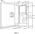
- FIG. 1 an environmental view of an exemplary embodiment of a galley 100 having a message center 102 and secure utensil storage drawer 104 is shown.
- the message center 102 is disposed in a galley bulkhead, either as an integral component of the bulkhead or a self-contained element suitable for retrofitting in existing bulkheads.
- the message center 102 defines one or more recessed portions 106, at least one recessed portion 200 configured to allow a tablet 108 in a docking element 110 to sit substantially flush with the surrounding bulkhead surface.
- the tablet 108 may be held in the recessed portion 106 by a releasable latch 112.
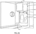
- a docking element 110 may include a charging element 202 for charging the tablet 108 while docked.
- the docking element 110 may support adapters to the charging element 202 for different tablets 108.
- the charging element 110 may be hinged within a range to allow the tablet 108 to rotate when a latch is release to facilitate removal of the tablet 108 from the docking element 110.
- a lower recessed portion 204 is adapted for reusable adhesive notes 206, 208.
- the lower recessed portion 204 may include a polished surface to facilitate adhesion of the relatively weak reusable adhesive.
- the lower recessed portion 204 may include a slightly adhesive silicone layer to enhance adhesion.
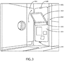
- FIG. 3 an environmental view of an exemplary embodiment of a message center 300 and secure utensil storage drawer 104 is shown.
- a docking element 306 may be hinged to allow the tablet 108 to rotate when an upper latch 308 is release to rotate from an upper recessed portion 302 to a lower recessed portion 304 without being removed from the docking element 306.
- the screen of the tablet 108 abuts a surface of the lower recessed portion 304 to protect the screen and prevent accidental or undesirable contact.
- a lower latch 310 may maintain the tablet 108 in the lower recessed portion 304 and work to bias the tablet toward the surface of the lower recessed portion 304 so that the tablet 108 remains substantially flush with the surface of the bulkhead so as to not incumber the secure utensil storage drawer 104
- a lower recessed portion 304 is adapted for reusable adhesive notes.
- the lower recessed portion 304 may include a polished surface to facilitate adhesion of the relatively weak reusable adhesive.
- the lower recessed portion 304 may include a slightly adhesive silicone layer to enhance adhesion.
- a slightly adhesive silicone layer may prevent scratches to the screen of the tablet 108 when secured within the lower recessed portion 304.
- FIG. 4 an environmental view of an exemplary embodiment of a secure utensil storage drawer 400 is shown.
- the secure utensil storage drawer 400 is vertically oriented and disposed so as to obscure a tablet-based galley message center (obscured) when fully extended.
- the secure utensil storage drawer 400 includes a plurality of securing features 402, 404, 406, 408 for securing various types of utensils.
- a hook 402 is affixed to extend from a vertical surface of the secure utensil storage drawer 400.
- the hook 402 comprises a T-shaped element such that the utensil must be inserted horizontally and rotated to hang vertically.
- the secure utensil storage drawer 400 includes one or more clips 404 for holding utensils with a solid handle or other flat surface to grab.
- the clips 404 may be spring biased to hold such utensils.
- the clips 404 are secured at fixed locations within the secure utensil storage drawer 400.
- the clips 404 may be magnetized and the secure utensil storage drawer 400 includes a vertical surface of a ferrous metal.
- the vertical surface of the secure utensil storage drawer 400 includes one or more elastic bands 406, 408 for holding utensils such as tongs.
- the secure utensil storage drawer 400 includes one or more bins 410, defined either by a self-contained insert or a lower surface of the secure utensil storage drawer 400.
- the secure utensil storage drawer 500 includes one or more magnetic elements 502 disposed on a vertical surface for securing metal utensils.
- an embodiment including a vertical surface with magnetic elements 502 and a vertical surface with other securing features (as shown in FIG. 4 ), where the vertical surface with magnetic elements 502 comprises a sliding surface disposed in front of the vertical surface with other securing features such that the magnetically retained utensils may be slid back and forth.
Landscapes
- Engineering & Computer Science (AREA)
- Aviation & Aerospace Engineering (AREA)
- Drawers Of Furniture (AREA)
- Combinations Of Kitchen Furniture (AREA)
Abstract
Description
- Aircraft, especially crew work areas of aircraft, are space constrained. All of the available space is generally highly utilized with little free space. Furthermore, the work areas are busy and utilitarian. There are no features for securely storing messages and messaging devices while still making them available for use. Likewise, there are no features for securely storing kitchen utensils while still making them readily available.
- In one aspect, embodiments of the inventive concepts disclosed herein are directed to a galley message center and secure utensil storage drawer. The message center defines a tablet recess were a tablet is docked, substantially flush with the surrounding bulkhead. Where the tablet is flush when docked, the utensil storage drawer may be closely disposed to the message center and slide out in front of the tablet without the tablet needing to be removed.
- In a further aspect, the docking element of the message center may be hinged to allow the tablet to be folded down with the screen against a recessed surface to protect the screen and prevent undesired or accidental interaction.
- The utensil storage drawer includes a plurality of features for securely holding utensils when not in use. The utensil storage draw places all of the stored utensils within reach of the flight staff, in proximity to a galley working surface.
- It is to be understood that both the foregoing general description and the following detailed description are exemplary and explanatory only and should not restrict the scope of the claims. The accompanying drawings, which are incorporated in and constitute a part of the specification, illustrate exemplary embodiments of the inventive concepts disclosed herein and together with the general description, serve to explain the principles.
- The numerous advantages of the embodiments of the inventive concepts disclosed herein may be better understood by those skilled in the art by reference to the accompanying figures in which:
- FIG. 1
- shows an environmental view of an exemplary embodiment of a message center and secure utensil storage drawer;
- FIG. 2A
- shows an environmental view of an exemplary embodiment of a message center and secure utensil storage drawer;
- FIG. 2B
- shows a detail view of an exemplary embodiment of a message center of
FIG. 2A ; - FIG. 3
- shows an environmental view of an exemplary embodiment of a message center and secure utensil storage drawer;
- FIG. 4
- shows an environmental view of an exemplary embodiment of a secure utensil storage drawer;
- FIG. 5
- shows an environmental view of an exemplary embodiment of a secure utensil storage drawer;
- Before explaining at least one embodiment of the inventive concepts disclosed herein in detail, it is to be understood that the inventive concepts are not limited in their application to the details of construction and the arrangement of the components or steps or methodologies set forth in the following description or illustrated in the drawings. In the following detailed description of embodiments of the instant inventive concepts, numerous specific details are set forth in order to provide a more thorough understanding of the inventive concepts. However, it will be apparent to one of ordinary skill in the art having the benefit of the instant disclosure that the inventive concepts disclosed herein may be practiced without these specific details. In other instances, well-known features may not be described in detail to avoid unnecessarily complicating the instant disclosure. The inventive concepts disclosed herein are capable of other embodiments or of being practiced or carried out in various ways. Also, it is to be understood that the phraseology and terminology employed herein is for the purpose of description and should not be regarded as limiting.
- As used herein a letter following a reference numeral is intended to reference an embodiment of the feature or element that may be similar, but not necessarily identical, to a previously described element or feature bearing the same reference numeral (e.g., 1, 1a, 1b). Such shorthand notations are used for purposes of convenience only, and should not be construed to limit the inventive concepts disclosed herein in any way unless expressly stated to the contrary.
- Further, unless expressly stated to the contrary, "or" refers to an inclusive or and not to an exclusive or. For example, a condition A or B is satisfied by anyone of the following: A is true (or present) and B is false (or not present), A is false (or not present) and B is true (or present), and both A and B are true (or present).
- In addition, use of the "a" or "an" are employed to describe elements and components of embodiments of the instant inventive concepts. This is done merely for convenience and to give a general sense of the inventive concepts, and "a" and "an" are intended to include one or at least one and the singular also includes the plural unless it is obvious that it is meant otherwise.
- Finally, as used herein any reference to "one embodiment," or "some embodiments" means that a particular element, feature, structure, or characteristic described in connection with the embodiment is included in at least one embodiment of the inventive concepts disclosed herein. The appearances of the phrase "in some embodiments" in various places in the specification are not necessarily all referring to the same embodiment, and embodiments of the inventive concepts disclosed may include one or more of the features expressly described or inherently present herein, or any combination of sub-combination of two or more such features, along with any other features which may not necessarily be expressly described or inherently present in the instant disclosure.
- Broadly, embodiments of the inventive concepts disclosed herein are directed to a galley message center and secure utensil storage drawer. The message center defines a tablet recess were a tablet is docked, substantially flush with the surrounding bulkhead. Where the tablet is flush when docked, the utensil storage drawer may be closely disposed to the message center and slide out in front of the tablet without the tablet needing to be removed.
- Referring to
FIG. 1 , an environmental view of an exemplary embodiment of agalley 100 having amessage center 102 and secureutensil storage drawer 104 is shown. Themessage center 102 is disposed in a galley bulkhead, either as an integral component of the bulkhead or a self-contained element suitable for retrofitting in existing bulkheads. Themessage center 102 defines one or morerecessed portions 106, at least onerecessed portion 200 configured to allow atablet 108 in adocking element 110 to sit substantially flush with the surrounding bulkhead surface. Thetablet 108 may be held in therecessed portion 106 by areleasable latch 112. - Referring to
FIG. 2A-2B , an environmental view and detail view of an exemplary embodiment of amessage center 102 and secureutensil storage drawer 104 are shown. Where atablet 108 is releasably held in an upperrecessed portion 200, adocking element 110 may include acharging element 202 for charging thetablet 108 while docked. Thedocking element 110 may support adapters to thecharging element 202 fordifferent tablets 108. Furthermore, thecharging element 110 may be hinged within a range to allow thetablet 108 to rotate when a latch is release to facilitate removal of thetablet 108 from thedocking element 110. - In at least one embodiment, a lower recessed
portion 204 is adapted for reusableadhesive notes portion 204 may include a polished surface to facilitate adhesion of the relatively weak reusable adhesive. Alternatively, the lowerrecessed portion 204 may include a slightly adhesive silicone layer to enhance adhesion. - Referring to
FIG. 3 , an environmental view of an exemplary embodiment of amessage center 300 and secureutensil storage drawer 104 is shown. Where atablet 108 is releasably held in an upperrecessed portion 302, adocking element 306 may be hinged to allow thetablet 108 to rotate when anupper latch 308 is release to rotate from an upper recessedportion 302 to a lower recessedportion 304 without being removed from thedocking element 306. After rotation, the screen of thetablet 108 abuts a surface of the lower recessedportion 304 to protect the screen and prevent accidental or undesirable contact. Alower latch 310 may maintain thetablet 108 in the lower recessedportion 304 and work to bias the tablet toward the surface of the lower recessedportion 304 so that thetablet 108 remains substantially flush with the surface of the bulkhead so as to not incumber the secureutensil storage drawer 104 - In at least one embodiment, a lower recessed
portion 304 is adapted for reusable adhesive notes. For example, the lower recessedportion 304 may include a polished surface to facilitate adhesion of the relatively weak reusable adhesive. Alternatively, the lower recessedportion 304 may include a slightly adhesive silicone layer to enhance adhesion. In at least one embodiment, a slightly adhesive silicone layer may prevent scratches to the screen of thetablet 108 when secured within the lower recessedportion 304. - Referring to
FIG. 4 , an environmental view of an exemplary embodiment of a secureutensil storage drawer 400 is shown. The secureutensil storage drawer 400 is vertically oriented and disposed so as to obscure a tablet-based galley message center (obscured) when fully extended. The secureutensil storage drawer 400 includes a plurality of securingfeatures hook 402 is affixed to extend from a vertical surface of the secureutensil storage drawer 400. In at least one embodiment, thehook 402 comprises a T-shaped element such that the utensil must be inserted horizontally and rotated to hang vertically. - In at least one embodiment, the secure
utensil storage drawer 400 includes one ormore clips 404 for holding utensils with a solid handle or other flat surface to grab. Theclips 404 may be spring biased to hold such utensils. In at least one embodiment, theclips 404 are secured at fixed locations within the secureutensil storage drawer 400. In other embodiments, theclips 404 may be magnetized and the secureutensil storage drawer 400 includes a vertical surface of a ferrous metal. - In at least one embodiment, the vertical surface of the secure
utensil storage drawer 400 includes one or moreelastic bands - In at least one embodiment, the secure
utensil storage drawer 400 includes one ormore bins 410, defined either by a self-contained insert or a lower surface of the secureutensil storage drawer 400. - Referring to
FIG. 5 , an environmental view of an exemplary embodiment of a secureutensil storage drawer 500 is shown. The secureutensil storage drawer 500 includes one or moremagnetic elements 502 disposed on a vertical surface for securing metal utensils. In at least one embodiment, an embodiment including a vertical surface withmagnetic elements 502 and a vertical surface with other securing features (as shown inFIG. 4 ), where the vertical surface withmagnetic elements 502 comprises a sliding surface disposed in front of the vertical surface with other securing features such that the magnetically retained utensils may be slid back and forth. - It is believed that the inventive concepts disclosed herein and many of their attendant advantages will be understood by the foregoing description of embodiments of the inventive concepts disclosed, and it will be apparent that various changes may be made in the form, construction, and arrangement of the components thereof without departing from the broad scope of the inventive concepts disclosed herein or without sacrificing all of their material advantages; and individual features from various embodiments may be combined to arrive at other embodiments. The form herein before described being merely an explanatory embodiment thereof, it is the intention of the following claims to encompass and include such changes. Furthermore, any of the features disclosed in relation to any of the individual embodiments may be incorporated into any other embodiment.
Claims (15)
- An aircraft galley message center (102) comprising:a recessed portion (106) defined by an aircraft bulkhead;a docking element (110) configured to hold a tablet (108) within the recessed portion, substantially flush with a surface of the aircraft bulkhead; anda charging element (202) disposed within the docking element (110).
- The galley message center of Claim 1, further comprising an upper latch (112) configured to retain the tablet in the recessed portion.
- The galley message center of Claims 1 or 2, wherein the docking element (110) is configured to rotate, and preferably wherein the docking element (110) is configured to rotate the tablet from an upper recessed portion with a screen of the tablet facing out and accessible to a crewmember, to a lower recessed portion (204) with the screen of the tablet facing a surface of the recessed portion, and more preferably further comprising a lower latch configured to retain the tablet in the lower recessed portion, and more preferably further comprising a silicone layer disposed on the tablet facing surface of the lower recessed portion (204).
- The galley message center of any preceding Claim, wherein the recessed portion comprises an upper recessed portion (200) configured to receive the tablet and a lower recessed portion (204) adapted to receive self-adhesive notes (206, 208).
- A secure aircraft utensil drawer (400) comprising:a. a vertical slideout disposed in an aircraft galley bulkhead; andb. a plurality of utensil retaining features (402, 404, 406, 408) disposed on a vertical surface of the vertical slideout,c. wherein:i. the plurality of utensil retaining features comprises at least one closed finger loop hook (402), at least one clip (404), and at least one elastic band (406, 408).
- The secure aircraft utensil drawer of Claim 5, further comprising one or more bin (410) disposed on a lower horizontal surface.
- The secure aircraft utensil drawer of Claim 5 or 6, further comprising one or more magnetic elements (502) disposed on the vertical surface.
- The secure aircraft utensil drawer of any of Claims 5-7, wherein the vertical surface comprises a first vertical surface, and wherein the secure utensil drawer further comprises a second vertical surface comprising one or more magnetic element, the second vertical surface being disposed in front of the first vertical surface, and being laterally displaceable.
- The secure aircraft utensil drawer of any of Claims 5-8, wherein the at least one hook comprises a T-shaped element.
- An aircraft galley comprising:a. a message center (102) as claimed in claim 1; andb. a secure utensil drawer comprising:i. a vertical slideout disposed in an aircraft galley bulkhead;ii. a plurality of utensil retaining features disposed on a vertical surface of the vertical slideout; andiii. one or more bin disposed on a lower horizontal surface,c. wherein:i. the plurality of utensil retaining features comprises at least one closed finger loop hook, at least one clip, and at least one elastic band.
- The aircraft galley of Claim 10, wherein the secure utensil drawer further comprises one or more magnetic elements (502) disposed on the vertical surface.
- The aircraft galley of Claim 10 or 11, wherein the vertical surface comprises a first vertical surface, and wherein the secure utensil drawer further comprises a second vertical surface comprising one or more magnetic element, the second vertical surface being disposed in front of the first vertical surface, and being laterally displaceable.
- The aircraft galley of any of Claims 10-12, wherein the at least one hook comprises a T-shaped element.
- The aircraft galley of any of Claims 10-13, wherein the docking element is configured to rotate the tablet from an upper recessed portion with a screen of the tablet facing out and accessible to a crewmember, to a lower recessed portion with the screen of the tablet facing a surface of the recessed portion, and preferably further comprising a lower latch configured to retain the tablet in the lower recessed portion, and more preferably further comprising a silicone layer disposed on the tablet facing surface of the lower recessed portion.
- The aircraft galley of any of Claims 10-14, wherein the recessed portion comprises an upper recessed portion configured to receive the tablet and a lower recessed portion adapted to receive self-adhesive notes.
Applications Claiming Priority (1)
| Application Number | Priority Date | Filing Date | Title |
|---|---|---|---|
| US16/801,428 US11623748B2 (en) | 2020-02-26 | 2020-02-26 | Galley slide out utensil drawer and message center |
Publications (3)
| Publication Number | Publication Date |
|---|---|
| EP3871974A2 true EP3871974A2 (en) | 2021-09-01 |
| EP3871974A3 EP3871974A3 (en) | 2021-11-10 |
| EP3871974B1 EP3871974B1 (en) | 2024-10-02 |
Family
ID=74732615
Family Applications (1)
| Application Number | Title | Priority Date | Filing Date |
|---|---|---|---|
| EP21158717.5A Active EP3871974B1 (en) | 2020-02-26 | 2021-02-23 | Galley slide out utensil drawer and message center |
Country Status (3)
| Country | Link |
|---|---|
| US (1) | US11623748B2 (en) |
| EP (1) | EP3871974B1 (en) |
| CN (1) | CN113303609B (en) |
Families Citing this family (4)
| Publication number | Priority date | Publication date | Assignee | Title |
|---|---|---|---|---|
| US11235879B2 (en) * | 2016-07-12 | 2022-02-01 | B/E Aerospace, Inc. | Aircraft service trolley and galley enclosure therefor |
| USD1001703S1 (en) * | 2021-02-19 | 2023-10-17 | Rh Us, Llc | Aircraft lavatory |
| USD1002488S1 (en) * | 2021-02-19 | 2023-10-24 | Rh Us, Llc | Aircraft galley |
| USD1051000S1 (en) * | 2023-03-16 | 2024-11-12 | Textron Innovations, Inc. | Digital side display extension |
Family Cites Families (34)
| Publication number | Priority date | Publication date | Assignee | Title |
|---|---|---|---|---|
| EP0183887A1 (en) * | 1984-11-29 | 1986-06-11 | Beniamino Pavarin | Fencing screen for children at the cooking plane and the kitchen cooking control |
| US4756528A (en) * | 1986-07-24 | 1988-07-12 | Ramon Umashankar | Video system for passenger vehicles |
| US5388032A (en) * | 1993-05-04 | 1995-02-07 | Ibus Technologies, Inc. | Computer equipment monitor and discriminator |
| JPH0730832A (en) * | 1993-07-09 | 1995-01-31 | Fujitsu General Ltd | Flat display device |
| DE19822694C5 (en) | 1998-05-20 | 2009-01-15 | Volkswagen Ag | Stowable folding table |
| CN2339073Y (en) * | 1998-09-28 | 1999-09-22 | 魏勇 | Rotary pillow pad |
| US6254955B1 (en) * | 1999-07-20 | 2001-07-03 | Taiwan Hopax Chems. Mfg. Co., Ltd. | Self-stick writing note |
| US6409242B1 (en) * | 2000-11-14 | 2002-06-25 | Chung L. Chang | Flat thin screen T/V monitor automotive roof mount |
| US6590767B2 (en) * | 2001-10-05 | 2003-07-08 | Dell Products L.P. | Portable computer docking station for horizontal or vertical use |
| DE10256782A1 (en) * | 2002-12-05 | 2004-08-05 | Tesa Ag | Adhesive products |
| US20070199844A1 (en) * | 2004-11-30 | 2007-08-30 | Daley Charles A Iii | Computer bag |
| DE102005005654B4 (en) * | 2005-02-08 | 2018-02-15 | Recaro Aircraft Seating Gmbh & Co. Kg | System comprising a screen and control unit, and a seat |
| WO2007016617A2 (en) * | 2005-08-02 | 2007-02-08 | World Properties, Inc. | Silicone compositions, methods of manufacture, and articles formed therefrom |
| CN201063171Y (en) * | 2007-06-20 | 2008-05-21 | 张荣彪 | Improved display screen structure of currency count machine |
| US20090089841A1 (en) * | 2007-10-01 | 2009-04-02 | Lear Corporation | Seat-mounted electronics assembly |
| US8157337B2 (en) * | 2009-06-16 | 2012-04-17 | Edwin Dizon Manalang | Tool box storage assembly |
| CN102033573B (en) * | 2009-09-30 | 2013-04-24 | 英业达股份有限公司 | Display device and sliding structure thereof |
| US20110188197A1 (en) | 2010-02-03 | 2011-08-04 | Craig Jackson | Integrated audio and video port for portable electonic devices |
| CN202175000U (en) * | 2011-04-26 | 2012-03-28 | 程彰仪 | Novel seat computer device in car |
| US9415872B2 (en) * | 2012-03-23 | 2016-08-16 | B/E Aerospace, Inc. | Integrated aircraft galley and appliance operating system |
| DE102012224091A1 (en) * | 2012-12-20 | 2014-07-10 | Lufthansa Systems Ag | Method of protecting a passenger and arrangement of folding table and seat screen |
| KR200480389Y1 (en) | 2014-10-08 | 2016-05-18 | 주식회사 일광산업 | Multi-fetched expressions cabinet |
| CN204432552U (en) * | 2015-01-21 | 2015-07-01 | 深圳车宝宝电子科技有限公司 | A kind of car entertainment device |
| CN105150950A (en) * | 2015-09-10 | 2015-12-16 | 姜超 | Vehicle-mounted television set |
| CN106370191A (en) * | 2016-08-22 | 2017-02-01 | 成都康普斯北斗科技有限公司 | BDS system-based vehicle-mounted navigation device |
| DE102017201103B4 (en) | 2017-01-24 | 2025-04-10 | Airbus Operations Gmbh | On-board galley monument with charging station |
| CN207650513U (en) * | 2017-12-13 | 2018-07-24 | 广州旺淦电子科技有限公司 | A kind of magnetic-attracting type liquid crystal display screen |
| DE102018200139A1 (en) * | 2018-01-08 | 2019-07-11 | Airbus Operations Gmbh | Galley monument with integrated display arrangement |
| CN108175199B (en) * | 2018-01-08 | 2024-04-16 | 傅峰峰 | Highly integrated intelligent automatic kitchen |
| DE102018205267A1 (en) | 2018-04-09 | 2019-10-10 | Airbus Operations Gmbh | Onboard kitchen monument for an aircraft |
| US11124299B2 (en) | 2018-04-10 | 2021-09-21 | Rockwell Collins, Inc. | Multi-mode transformable monuments for aircraft doorway spaces |
| CN108583459B (en) * | 2018-05-29 | 2020-07-03 | 安徽奇点智能科技有限公司 | Audio-visual play device for unmanned vehicle |
| US11305876B2 (en) * | 2018-07-10 | 2022-04-19 | Rockwell Collins, Inc. | Aircraft cabin apparatus including personal electronic device holder |
| CN110584347A (en) | 2019-08-07 | 2019-12-20 | 福建省安溪升聚贸易有限公司 | Cabinet for smart home |
-
2020
- 2020-02-26 US US16/801,428 patent/US11623748B2/en active Active
-
2021
- 2021-02-23 EP EP21158717.5A patent/EP3871974B1/en active Active
- 2021-02-26 CN CN202110216557.9A patent/CN113303609B/en active Active
Also Published As
| Publication number | Publication date |
|---|---|
| EP3871974B1 (en) | 2024-10-02 |
| EP3871974A3 (en) | 2021-11-10 |
| CN113303609B (en) | 2024-07-30 |
| US20210261258A1 (en) | 2021-08-26 |
| CN113303609A (en) | 2021-08-27 |
| US11623748B2 (en) | 2023-04-11 |
Similar Documents
| Publication | Publication Date | Title |
|---|---|---|
| EP3871974B1 (en) | Galley slide out utensil drawer and message center | |
| US9415874B2 (en) | Configurable tray table | |
| US6453588B1 (en) | Magnetically receptive shopping cart carrier plate | |
| EP2694367B1 (en) | Seatback holder for tablet computers | |
| US20200400267A1 (en) | Magnetic Socket Mount | |
| US8807406B1 (en) | Multi-purpose convertible carrier | |
| US5975475A (en) | Fire extinguisher holder | |
| US20140054338A1 (en) | Vacuum Mount System For Portable Electronic Device | |
| US9282842B1 (en) | System for holding dispensing bottles | |
| EP3350022B1 (en) | Portable electronic device holder for tray tables | |
| EP3258816B1 (en) | Hook systems for hanging school bags | |
| US10391951B2 (en) | Support systems for portable electronic devices | |
| US4120109A (en) | Extended magazine holder | |
| US20050139739A1 (en) | Magnetic-adhesive mounting device | |
| US9876885B1 (en) | Cell phone case with integrated hooks | |
| US7461750B2 (en) | Universal storage system for office tools | |
| US6471169B1 (en) | Multiple object support means for walls and method of use | |
| US20110240810A1 (en) | Cup Holder | |
| US7815051B2 (en) | Container system | |
| US10369915B1 (en) | Portable beverage holder | |
| US6802174B2 (en) | Method of administering first-aid in a vehicle | |
| US10207653B1 (en) | Stowable tiered electronic device holder | |
| EP3146863A1 (en) | Magnetic latching system | |
| US20180050840A1 (en) | Magnetic tool system and method | |
| US6315254B1 (en) | Object support means for walls and method of use |
Legal Events
| Date | Code | Title | Description |
|---|---|---|---|
| PUAI | Public reference made under article 153(3) epc to a published international application that has entered the european phase |
Free format text: ORIGINAL CODE: 0009012 |
|
| STAA | Information on the status of an ep patent application or granted ep patent |
Free format text: STATUS: THE APPLICATION HAS BEEN PUBLISHED |
|
| AK | Designated contracting states |
Kind code of ref document: A2 Designated state(s): AL AT BE BG CH CY CZ DE DK EE ES FI FR GB GR HR HU IE IS IT LI LT LU LV MC MK MT NL NO PL PT RO RS SE SI SK SM TR |
|
| PUAL | Search report despatched |
Free format text: ORIGINAL CODE: 0009013 |
|
| AK | Designated contracting states |
Kind code of ref document: A3 Designated state(s): AL AT BE BG CH CY CZ DE DK EE ES FI FR GB GR HR HU IE IS IT LI LT LU LV MC MK MT NL NO PL PT RO RS SE SI SK SM TR |
|
| RIC1 | Information provided on ipc code assigned before grant |
Ipc: A47B 88/988 20170101ALI20211004BHEP Ipc: A47B 88/42 20170101ALI20211004BHEP Ipc: A47B 77/14 20060101ALI20211004BHEP Ipc: B64D 11/04 20060101AFI20211004BHEP |
|
| STAA | Information on the status of an ep patent application or granted ep patent |
Free format text: STATUS: REQUEST FOR EXAMINATION WAS MADE |
|
| 17P | Request for examination filed |
Effective date: 20220504 |
|
| RBV | Designated contracting states (corrected) |
Designated state(s): AL AT BE BG CH CY CZ DE DK EE ES FI FR GB GR HR HU IE IS IT LI LT LU LV MC MK MT NL NO PL PT RO RS SE SI SK SM TR |
|
| STAA | Information on the status of an ep patent application or granted ep patent |
Free format text: STATUS: EXAMINATION IS IN PROGRESS |
|
| 17Q | First examination report despatched |
Effective date: 20230306 |
|
| P01 | Opt-out of the competence of the unified patent court (upc) registered |
Effective date: 20230922 |
|
| GRAP | Despatch of communication of intention to grant a patent |
Free format text: ORIGINAL CODE: EPIDOSNIGR1 |
|
| STAA | Information on the status of an ep patent application or granted ep patent |
Free format text: STATUS: GRANT OF PATENT IS INTENDED |
|
| INTG | Intention to grant announced |
Effective date: 20240502 |
|
| GRAS | Grant fee paid |
Free format text: ORIGINAL CODE: EPIDOSNIGR3 |
|
| GRAA | (expected) grant |
Free format text: ORIGINAL CODE: 0009210 |
|
| STAA | Information on the status of an ep patent application or granted ep patent |
Free format text: STATUS: THE PATENT HAS BEEN GRANTED |
|
| AK | Designated contracting states |
Kind code of ref document: B1 Designated state(s): AL AT BE BG CH CY CZ DE DK EE ES FI FR GB GR HR HU IE IS IT LI LT LU LV MC MK MT NL NO PL PT RO RS SE SI SK SM TR |
|
| REG | Reference to a national code |
Ref country code: GB Ref legal event code: FG4D |
|
| REG | Reference to a national code |
Ref country code: CH Ref legal event code: EP |
|
| REG | Reference to a national code |
Ref country code: IE Ref legal event code: FG4D |
|
| REG | Reference to a national code |
Ref country code: DE Ref legal event code: R096 Ref document number: 602021019484 Country of ref document: DE |
|
| REG | Reference to a national code |
Ref country code: LT Ref legal event code: MG9D |
|
| REG | Reference to a national code |
Ref country code: NL Ref legal event code: MP Effective date: 20241002 |
|
| REG | Reference to a national code |
Ref country code: AT Ref legal event code: MK05 Ref document number: 1728295 Country of ref document: AT Kind code of ref document: T Effective date: 20241002 |
|
| PG25 | Lapsed in a contracting state [announced via postgrant information from national office to epo] |
Ref country code: NL Free format text: LAPSE BECAUSE OF FAILURE TO SUBMIT A TRANSLATION OF THE DESCRIPTION OR TO PAY THE FEE WITHIN THE PRESCRIBED TIME-LIMIT Effective date: 20241002 |
|
| PG25 | Lapsed in a contracting state [announced via postgrant information from national office to epo] |
Ref country code: NL Free format text: LAPSE BECAUSE OF FAILURE TO SUBMIT A TRANSLATION OF THE DESCRIPTION OR TO PAY THE FEE WITHIN THE PRESCRIBED TIME-LIMIT Effective date: 20241002 |
|
| PG25 | Lapsed in a contracting state [announced via postgrant information from national office to epo] |
Ref country code: IS Free format text: LAPSE BECAUSE OF FAILURE TO SUBMIT A TRANSLATION OF THE DESCRIPTION OR TO PAY THE FEE WITHIN THE PRESCRIBED TIME-LIMIT Effective date: 20250202 Ref country code: HR Free format text: LAPSE BECAUSE OF FAILURE TO SUBMIT A TRANSLATION OF THE DESCRIPTION OR TO PAY THE FEE WITHIN THE PRESCRIBED TIME-LIMIT Effective date: 20241002 Ref country code: PT Free format text: LAPSE BECAUSE OF FAILURE TO SUBMIT A TRANSLATION OF THE DESCRIPTION OR TO PAY THE FEE WITHIN THE PRESCRIBED TIME-LIMIT Effective date: 20250203 |
|
| PG25 | Lapsed in a contracting state [announced via postgrant information from national office to epo] |
Ref country code: FI Free format text: LAPSE BECAUSE OF FAILURE TO SUBMIT A TRANSLATION OF THE DESCRIPTION OR TO PAY THE FEE WITHIN THE PRESCRIBED TIME-LIMIT Effective date: 20241002 |
|
| PG25 | Lapsed in a contracting state [announced via postgrant information from national office to epo] |
Ref country code: BG Free format text: LAPSE BECAUSE OF FAILURE TO SUBMIT A TRANSLATION OF THE DESCRIPTION OR TO PAY THE FEE WITHIN THE PRESCRIBED TIME-LIMIT Effective date: 20241002 |
|
| PG25 | Lapsed in a contracting state [announced via postgrant information from national office to epo] |
Ref country code: ES Free format text: LAPSE BECAUSE OF FAILURE TO SUBMIT A TRANSLATION OF THE DESCRIPTION OR TO PAY THE FEE WITHIN THE PRESCRIBED TIME-LIMIT Effective date: 20241002 |
|
| PG25 | Lapsed in a contracting state [announced via postgrant information from national office to epo] |
Ref country code: NO Free format text: LAPSE BECAUSE OF FAILURE TO SUBMIT A TRANSLATION OF THE DESCRIPTION OR TO PAY THE FEE WITHIN THE PRESCRIBED TIME-LIMIT Effective date: 20250102 |
|
| PG25 | Lapsed in a contracting state [announced via postgrant information from national office to epo] |
Ref country code: GR Free format text: LAPSE BECAUSE OF FAILURE TO SUBMIT A TRANSLATION OF THE DESCRIPTION OR TO PAY THE FEE WITHIN THE PRESCRIBED TIME-LIMIT Effective date: 20250103 Ref country code: AT Free format text: LAPSE BECAUSE OF FAILURE TO SUBMIT A TRANSLATION OF THE DESCRIPTION OR TO PAY THE FEE WITHIN THE PRESCRIBED TIME-LIMIT Effective date: 20241002 Ref country code: LV Free format text: LAPSE BECAUSE OF FAILURE TO SUBMIT A TRANSLATION OF THE DESCRIPTION OR TO PAY THE FEE WITHIN THE PRESCRIBED TIME-LIMIT Effective date: 20241002 |
|
| PG25 | Lapsed in a contracting state [announced via postgrant information from national office to epo] |
Ref country code: PL Free format text: LAPSE BECAUSE OF FAILURE TO SUBMIT A TRANSLATION OF THE DESCRIPTION OR TO PAY THE FEE WITHIN THE PRESCRIBED TIME-LIMIT Effective date: 20241002 Ref country code: CZ Free format text: LAPSE BECAUSE OF FAILURE TO SUBMIT A TRANSLATION OF THE DESCRIPTION OR TO PAY THE FEE WITHIN THE PRESCRIBED TIME-LIMIT Effective date: 20241002 |
|
| PG25 | Lapsed in a contracting state [announced via postgrant information from national office to epo] |
Ref country code: RS Free format text: LAPSE BECAUSE OF FAILURE TO SUBMIT A TRANSLATION OF THE DESCRIPTION OR TO PAY THE FEE WITHIN THE PRESCRIBED TIME-LIMIT Effective date: 20250102 |
|
| PG25 | Lapsed in a contracting state [announced via postgrant information from national office to epo] |
Ref country code: SM Free format text: LAPSE BECAUSE OF FAILURE TO SUBMIT A TRANSLATION OF THE DESCRIPTION OR TO PAY THE FEE WITHIN THE PRESCRIBED TIME-LIMIT Effective date: 20241002 |
|
| REG | Reference to a national code |
Ref country code: DE Ref legal event code: R097 Ref document number: 602021019484 Country of ref document: DE |
|
| PG25 | Lapsed in a contracting state [announced via postgrant information from national office to epo] |
Ref country code: DK Free format text: LAPSE BECAUSE OF FAILURE TO SUBMIT A TRANSLATION OF THE DESCRIPTION OR TO PAY THE FEE WITHIN THE PRESCRIBED TIME-LIMIT Effective date: 20241002 |
|
| PG25 | Lapsed in a contracting state [announced via postgrant information from national office to epo] |
Ref country code: EE Free format text: LAPSE BECAUSE OF FAILURE TO SUBMIT A TRANSLATION OF THE DESCRIPTION OR TO PAY THE FEE WITHIN THE PRESCRIBED TIME-LIMIT Effective date: 20241002 |
|
| PG25 | Lapsed in a contracting state [announced via postgrant information from national office to epo] |
Ref country code: RO Free format text: LAPSE BECAUSE OF FAILURE TO SUBMIT A TRANSLATION OF THE DESCRIPTION OR TO PAY THE FEE WITHIN THE PRESCRIBED TIME-LIMIT Effective date: 20241002 |
|
| PG25 | Lapsed in a contracting state [announced via postgrant information from national office to epo] |
Ref country code: SK Free format text: LAPSE BECAUSE OF FAILURE TO SUBMIT A TRANSLATION OF THE DESCRIPTION OR TO PAY THE FEE WITHIN THE PRESCRIBED TIME-LIMIT Effective date: 20241002 |
|
| PG25 | Lapsed in a contracting state [announced via postgrant information from national office to epo] |
Ref country code: IT Free format text: LAPSE BECAUSE OF FAILURE TO SUBMIT A TRANSLATION OF THE DESCRIPTION OR TO PAY THE FEE WITHIN THE PRESCRIBED TIME-LIMIT Effective date: 20241002 |
|
| PLBE | No opposition filed within time limit |
Free format text: ORIGINAL CODE: 0009261 |
|
| STAA | Information on the status of an ep patent application or granted ep patent |
Free format text: STATUS: NO OPPOSITION FILED WITHIN TIME LIMIT |
|
| PG25 | Lapsed in a contracting state [announced via postgrant information from national office to epo] |
Ref country code: SE Free format text: LAPSE BECAUSE OF FAILURE TO SUBMIT A TRANSLATION OF THE DESCRIPTION OR TO PAY THE FEE WITHIN THE PRESCRIBED TIME-LIMIT Effective date: 20241002 |
|
| 26N | No opposition filed |
Effective date: 20250703 |
|
| PG25 | Lapsed in a contracting state [announced via postgrant information from national office to epo] |
Ref country code: MC Free format text: LAPSE BECAUSE OF FAILURE TO SUBMIT A TRANSLATION OF THE DESCRIPTION OR TO PAY THE FEE WITHIN THE PRESCRIBED TIME-LIMIT Effective date: 20241002 |
|
| REG | Reference to a national code |
Ref country code: CH Ref legal event code: PL |
|
| PG25 | Lapsed in a contracting state [announced via postgrant information from national office to epo] |
Ref country code: LU Free format text: LAPSE BECAUSE OF NON-PAYMENT OF DUE FEES Effective date: 20250223 |
|
| PG25 | Lapsed in a contracting state [announced via postgrant information from national office to epo] |
Ref country code: CH Free format text: LAPSE BECAUSE OF NON-PAYMENT OF DUE FEES Effective date: 20250228 |
|
| REG | Reference to a national code |
Ref country code: BE Ref legal event code: MM Effective date: 20250228 |
|
| PG25 | Lapsed in a contracting state [announced via postgrant information from national office to epo] |
Ref country code: BE Free format text: LAPSE BECAUSE OF NON-PAYMENT OF DUE FEES Effective date: 20250228 |
|
| PG25 | Lapsed in a contracting state [announced via postgrant information from national office to epo] |
Ref country code: IE Free format text: LAPSE BECAUSE OF NON-PAYMENT OF DUE FEES Effective date: 20250223 |
|
| PGFP | Annual fee paid to national office [announced via postgrant information from national office to epo] |
Ref country code: GB Payment date: 20260121 Year of fee payment: 6 |
|
| PGFP | Annual fee paid to national office [announced via postgrant information from national office to epo] |
Ref country code: DE Payment date: 20260121 Year of fee payment: 6 |
|
| PGFP | Annual fee paid to national office [announced via postgrant information from national office to epo] |
Ref country code: FR Payment date: 20260121 Year of fee payment: 6 |