EP3871851A1 - Kneading device - Google Patents
Kneading device Download PDFInfo
- Publication number
- EP3871851A1 EP3871851A1 EP19903095.8A EP19903095A EP3871851A1 EP 3871851 A1 EP3871851 A1 EP 3871851A1 EP 19903095 A EP19903095 A EP 19903095A EP 3871851 A1 EP3871851 A1 EP 3871851A1
- Authority
- EP
- European Patent Office
- Prior art keywords
- kneading
- wear
- sensor
- wall face
- casing
- Prior art date
- Legal status (The legal status is an assumption and is not a legal conclusion. Google has not performed a legal analysis and makes no representation as to the accuracy of the status listed.)
- Withdrawn
Links
- 238000004898 kneading Methods 0.000 title claims abstract description 214
- 239000000463 material Substances 0.000 claims description 30
- 238000001816 cooling Methods 0.000 description 4
- 239000004033 plastic Substances 0.000 description 4
- 239000002861 polymer material Substances 0.000 description 4
- 239000000126 substance Substances 0.000 description 3
- VYPSYNLAJGMNEJ-UHFFFAOYSA-N Silicium dioxide Chemical compound O=[Si]=O VYPSYNLAJGMNEJ-UHFFFAOYSA-N 0.000 description 2
- 239000002994 raw material Substances 0.000 description 2
- 230000000630 rising effect Effects 0.000 description 2
- 238000005286 illumination Methods 0.000 description 1
- 230000004048 modification Effects 0.000 description 1
- 238000012986 modification Methods 0.000 description 1
- 230000004043 responsiveness Effects 0.000 description 1
- 239000000377 silicon dioxide Substances 0.000 description 1
- 239000003190 viscoelastic substance Substances 0.000 description 1
Images




Classifications
-
- B—PERFORMING OPERATIONS; TRANSPORTING
- B29—WORKING OF PLASTICS; WORKING OF SUBSTANCES IN A PLASTIC STATE IN GENERAL
- B29B—PREPARATION OR PRETREATMENT OF THE MATERIAL TO BE SHAPED; MAKING GRANULES OR PREFORMS; RECOVERY OF PLASTICS OR OTHER CONSTITUENTS OF WASTE MATERIAL CONTAINING PLASTICS
- B29B7/00—Mixing; Kneading
- B29B7/02—Mixing; Kneading non-continuous, with mechanical mixing or kneading devices, i.e. batch type
- B29B7/06—Mixing; Kneading non-continuous, with mechanical mixing or kneading devices, i.e. batch type with movable mixing or kneading devices
- B29B7/10—Mixing; Kneading non-continuous, with mechanical mixing or kneading devices, i.e. batch type with movable mixing or kneading devices rotary
- B29B7/18—Mixing; Kneading non-continuous, with mechanical mixing or kneading devices, i.e. batch type with movable mixing or kneading devices rotary with more than one shaft
- B29B7/183—Mixing; Kneading non-continuous, with mechanical mixing or kneading devices, i.e. batch type with movable mixing or kneading devices rotary with more than one shaft having a casing closely surrounding the rotors, e.g. of Banbury type
- B29B7/186—Rotors therefor
-
- B—PERFORMING OPERATIONS; TRANSPORTING
- B29—WORKING OF PLASTICS; WORKING OF SUBSTANCES IN A PLASTIC STATE IN GENERAL
- B29B—PREPARATION OR PRETREATMENT OF THE MATERIAL TO BE SHAPED; MAKING GRANULES OR PREFORMS; RECOVERY OF PLASTICS OR OTHER CONSTITUENTS OF WASTE MATERIAL CONTAINING PLASTICS
- B29B7/00—Mixing; Kneading
- B29B7/02—Mixing; Kneading non-continuous, with mechanical mixing or kneading devices, i.e. batch type
- B29B7/06—Mixing; Kneading non-continuous, with mechanical mixing or kneading devices, i.e. batch type with movable mixing or kneading devices
- B29B7/10—Mixing; Kneading non-continuous, with mechanical mixing or kneading devices, i.e. batch type with movable mixing or kneading devices rotary
- B29B7/18—Mixing; Kneading non-continuous, with mechanical mixing or kneading devices, i.e. batch type with movable mixing or kneading devices rotary with more than one shaft
- B29B7/183—Mixing; Kneading non-continuous, with mechanical mixing or kneading devices, i.e. batch type with movable mixing or kneading devices rotary with more than one shaft having a casing closely surrounding the rotors, e.g. of Banbury type
-
- B—PERFORMING OPERATIONS; TRANSPORTING
- B29—WORKING OF PLASTICS; WORKING OF SUBSTANCES IN A PLASTIC STATE IN GENERAL
- B29B—PREPARATION OR PRETREATMENT OF THE MATERIAL TO BE SHAPED; MAKING GRANULES OR PREFORMS; RECOVERY OF PLASTICS OR OTHER CONSTITUENTS OF WASTE MATERIAL CONTAINING PLASTICS
- B29B7/00—Mixing; Kneading
- B29B7/02—Mixing; Kneading non-continuous, with mechanical mixing or kneading devices, i.e. batch type
- B29B7/22—Component parts, details or accessories; Auxiliary operations
- B29B7/28—Component parts, details or accessories; Auxiliary operations for measuring, controlling or regulating, e.g. viscosity control
-
- B—PERFORMING OPERATIONS; TRANSPORTING
- B29—WORKING OF PLASTICS; WORKING OF SUBSTANCES IN A PLASTIC STATE IN GENERAL
- B29B—PREPARATION OR PRETREATMENT OF THE MATERIAL TO BE SHAPED; MAKING GRANULES OR PREFORMS; RECOVERY OF PLASTICS OR OTHER CONSTITUENTS OF WASTE MATERIAL CONTAINING PLASTICS
- B29B7/00—Mixing; Kneading
- B29B7/02—Mixing; Kneading non-continuous, with mechanical mixing or kneading devices, i.e. batch type
- B29B7/22—Component parts, details or accessories; Auxiliary operations
- B29B7/28—Component parts, details or accessories; Auxiliary operations for measuring, controlling or regulating, e.g. viscosity control
- B29B7/283—Component parts, details or accessories; Auxiliary operations for measuring, controlling or regulating, e.g. viscosity control measuring data of the driving system, e.g. torque, speed, power
-
- B—PERFORMING OPERATIONS; TRANSPORTING
- B29—WORKING OF PLASTICS; WORKING OF SUBSTANCES IN A PLASTIC STATE IN GENERAL
- B29B—PREPARATION OR PRETREATMENT OF THE MATERIAL TO BE SHAPED; MAKING GRANULES OR PREFORMS; RECOVERY OF PLASTICS OR OTHER CONSTITUENTS OF WASTE MATERIAL CONTAINING PLASTICS
- B29B7/00—Mixing; Kneading
- B29B7/02—Mixing; Kneading non-continuous, with mechanical mixing or kneading devices, i.e. batch type
- B29B7/22—Component parts, details or accessories; Auxiliary operations
- B29B7/28—Component parts, details or accessories; Auxiliary operations for measuring, controlling or regulating, e.g. viscosity control
- B29B7/286—Component parts, details or accessories; Auxiliary operations for measuring, controlling or regulating, e.g. viscosity control measuring properties of the mixture, e.g. temperature, density
-
- B—PERFORMING OPERATIONS; TRANSPORTING
- B29—WORKING OF PLASTICS; WORKING OF SUBSTANCES IN A PLASTIC STATE IN GENERAL
- B29B—PREPARATION OR PRETREATMENT OF THE MATERIAL TO BE SHAPED; MAKING GRANULES OR PREFORMS; RECOVERY OF PLASTICS OR OTHER CONSTITUENTS OF WASTE MATERIAL CONTAINING PLASTICS
- B29B7/00—Mixing; Kneading
- B29B7/74—Mixing; Kneading using other mixers or combinations of mixers, e.g. of dissimilar mixers ; Plant
- B29B7/7476—Systems, i.e. flow charts or diagrams; Plants
- B29B7/7495—Systems, i.e. flow charts or diagrams; Plants for mixing rubber
-
- B—PERFORMING OPERATIONS; TRANSPORTING
- B29—WORKING OF PLASTICS; WORKING OF SUBSTANCES IN A PLASTIC STATE IN GENERAL
- B29B—PREPARATION OR PRETREATMENT OF THE MATERIAL TO BE SHAPED; MAKING GRANULES OR PREFORMS; RECOVERY OF PLASTICS OR OTHER CONSTITUENTS OF WASTE MATERIAL CONTAINING PLASTICS
- B29B7/00—Mixing; Kneading
- B29B7/80—Component parts, details or accessories; Auxiliary operations
- B29B7/82—Heating or cooling
- B29B7/823—Temperature control
-
- B—PERFORMING OPERATIONS; TRANSPORTING
- B29—WORKING OF PLASTICS; WORKING OF SUBSTANCES IN A PLASTIC STATE IN GENERAL
- B29C—SHAPING OR JOINING OF PLASTICS; SHAPING OF MATERIAL IN A PLASTIC STATE, NOT OTHERWISE PROVIDED FOR; AFTER-TREATMENT OF THE SHAPED PRODUCTS, e.g. REPAIRING
- B29C48/00—Extrusion moulding, i.e. expressing the moulding material through a die or nozzle which imparts the desired form; Apparatus therefor
- B29C48/25—Component parts, details or accessories; Auxiliary operations
- B29C48/36—Means for plasticising or homogenising the moulding material or forcing it through the nozzle or die
- B29C48/395—Means for plasticising or homogenising the moulding material or forcing it through the nozzle or die using screws surrounded by a cooperating barrel, e.g. single screw extruders
- B29C48/40—Means for plasticising or homogenising the moulding material or forcing it through the nozzle or die using screws surrounded by a cooperating barrel, e.g. single screw extruders using two or more parallel screws or at least two parallel non-intermeshing screws, e.g. twin screw extruders
-
- B—PERFORMING OPERATIONS; TRANSPORTING
- B29—WORKING OF PLASTICS; WORKING OF SUBSTANCES IN A PLASTIC STATE IN GENERAL
- B29C—SHAPING OR JOINING OF PLASTICS; SHAPING OF MATERIAL IN A PLASTIC STATE, NOT OTHERWISE PROVIDED FOR; AFTER-TREATMENT OF THE SHAPED PRODUCTS, e.g. REPAIRING
- B29C48/00—Extrusion moulding, i.e. expressing the moulding material through a die or nozzle which imparts the desired form; Apparatus therefor
- B29C48/25—Component parts, details or accessories; Auxiliary operations
- B29C48/92—Measuring, controlling or regulating
-
- B—PERFORMING OPERATIONS; TRANSPORTING
- B29—WORKING OF PLASTICS; WORKING OF SUBSTANCES IN A PLASTIC STATE IN GENERAL
- B29B—PREPARATION OR PRETREATMENT OF THE MATERIAL TO BE SHAPED; MAKING GRANULES OR PREFORMS; RECOVERY OF PLASTICS OR OTHER CONSTITUENTS OF WASTE MATERIAL CONTAINING PLASTICS
- B29B7/00—Mixing; Kneading
- B29B7/30—Mixing; Kneading continuous, with mechanical mixing or kneading devices
- B29B7/58—Component parts, details or accessories; Auxiliary operations
- B29B7/72—Measuring, controlling or regulating
- B29B7/726—Measuring properties of mixture, e.g. temperature or density
-
- B—PERFORMING OPERATIONS; TRANSPORTING
- B29—WORKING OF PLASTICS; WORKING OF SUBSTANCES IN A PLASTIC STATE IN GENERAL
- B29B—PREPARATION OR PRETREATMENT OF THE MATERIAL TO BE SHAPED; MAKING GRANULES OR PREFORMS; RECOVERY OF PLASTICS OR OTHER CONSTITUENTS OF WASTE MATERIAL CONTAINING PLASTICS
- B29B7/00—Mixing; Kneading
- B29B7/30—Mixing; Kneading continuous, with mechanical mixing or kneading devices
- B29B7/58—Component parts, details or accessories; Auxiliary operations
- B29B7/72—Measuring, controlling or regulating
- B29B7/728—Measuring data of the driving system, e.g. torque, speed, power, vibration
-
- B—PERFORMING OPERATIONS; TRANSPORTING
- B29—WORKING OF PLASTICS; WORKING OF SUBSTANCES IN A PLASTIC STATE IN GENERAL
- B29C—SHAPING OR JOINING OF PLASTICS; SHAPING OF MATERIAL IN A PLASTIC STATE, NOT OTHERWISE PROVIDED FOR; AFTER-TREATMENT OF THE SHAPED PRODUCTS, e.g. REPAIRING
- B29C2948/00—Indexing scheme relating to extrusion moulding
- B29C2948/92—Measuring, controlling or regulating
- B29C2948/92009—Measured parameter
- B29C2948/92019—Pressure
-
- B—PERFORMING OPERATIONS; TRANSPORTING
- B29—WORKING OF PLASTICS; WORKING OF SUBSTANCES IN A PLASTIC STATE IN GENERAL
- B29C—SHAPING OR JOINING OF PLASTICS; SHAPING OF MATERIAL IN A PLASTIC STATE, NOT OTHERWISE PROVIDED FOR; AFTER-TREATMENT OF THE SHAPED PRODUCTS, e.g. REPAIRING
- B29C2948/00—Indexing scheme relating to extrusion moulding
- B29C2948/92—Measuring, controlling or regulating
- B29C2948/92009—Measured parameter
- B29C2948/92209—Temperature
-
- B—PERFORMING OPERATIONS; TRANSPORTING
- B29—WORKING OF PLASTICS; WORKING OF SUBSTANCES IN A PLASTIC STATE IN GENERAL
- B29C—SHAPING OR JOINING OF PLASTICS; SHAPING OF MATERIAL IN A PLASTIC STATE, NOT OTHERWISE PROVIDED FOR; AFTER-TREATMENT OF THE SHAPED PRODUCTS, e.g. REPAIRING
- B29C2948/00—Indexing scheme relating to extrusion moulding
- B29C2948/92—Measuring, controlling or regulating
- B29C2948/92009—Measured parameter
- B29C2948/92285—Surface properties
-
- B—PERFORMING OPERATIONS; TRANSPORTING
- B29—WORKING OF PLASTICS; WORKING OF SUBSTANCES IN A PLASTIC STATE IN GENERAL
- B29C—SHAPING OR JOINING OF PLASTICS; SHAPING OF MATERIAL IN A PLASTIC STATE, NOT OTHERWISE PROVIDED FOR; AFTER-TREATMENT OF THE SHAPED PRODUCTS, e.g. REPAIRING
- B29C2948/00—Indexing scheme relating to extrusion moulding
- B29C2948/92—Measuring, controlling or regulating
- B29C2948/92323—Location or phase of measurement
- B29C2948/92361—Extrusion unit
- B29C2948/9238—Feeding, melting, plasticising or pumping zones, e.g. the melt itself
- B29C2948/924—Barrel or housing
-
- B—PERFORMING OPERATIONS; TRANSPORTING
- B29—WORKING OF PLASTICS; WORKING OF SUBSTANCES IN A PLASTIC STATE IN GENERAL
- B29C—SHAPING OR JOINING OF PLASTICS; SHAPING OF MATERIAL IN A PLASTIC STATE, NOT OTHERWISE PROVIDED FOR; AFTER-TREATMENT OF THE SHAPED PRODUCTS, e.g. REPAIRING
- B29C2948/00—Indexing scheme relating to extrusion moulding
- B29C2948/92—Measuring, controlling or regulating
- B29C2948/92504—Controlled parameter
- B29C2948/9278—Surface properties
Definitions
- the present invention relates to a kneading device for kneading a high-polymer material, such as plastic and rubber, the kneading device having a function of detecting wear of an inner wall face of a kneading chamber.
- High-polymer materials such as plastic and rubber
- a high friction is created between a high-polymer material (knead-material), such as plastic and rubber and an inner wall face of a kneading chamber provided in a casing of the kneading device.
- knead-material high-polymer material
- a known example of the kneading device is an apparatus used for kneading a rubber which becomes a raw material of a tire.
- the internal-check apparatus includes an image capturing unit that can capture an image inside a kneading device, an illumination unit that can illuminate the inside of the kneading device, a suspending member that suspends the image capturing unit inside the kneading device and moves the image capturing unit in a vertical direction, and a manipulating unit through which the image capturing unit is manipulated from outside the kneading device.
- the internal-check apparatus Using the internal-check apparatus, the internal state of the kneading device can be observed by a small number of people. Thus, the inside of the kneading device can be checked easily.
- Patent Literature 1 JP 2016-37028 A
- An object of the present invention is to provide a kneading device that can check a progress of wear of an inner wall face of a kneading chamber without stopping the kneading device.
- a kneading device includes at least one kneading rotor that is rotated about a predetermined axis to knead a knead-material and includes a kneading blade that applies a shear force to the knead-material, the kneading blade including a kneading blade tip provided at an outermost regarding a radial direction of the kneading rotor, a casing including an inner wall face opposing the kneading blade tip with a predetermined gap between the inner wall face and the kneading blade tip and forming a kneading chamber housing the at least one kneading rotor to knead the knead-material, the casing being formed of a sensor-mount space separated from the inner wall face, the sensor-mount space including a bottom apart from the
- FIG. 1 is a front cross-sectional view illustrating the kneading device 1 according to the embodiment.
- FIG. 2A is an enlarged cross-sectional view illustrating an enlarged figure of a casing section of the kneading device 1 in FIG. 1 .
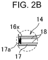
- FIG. 2B is an enlarged cross-sectional view illustrating a further enlarged figure of a portion (portion A) in FIG. 2A .
- the kneading device 1 includes a casing 3 having inside a kneading chamber 2, a pair of kneading rotors 4 and 5 (at least one kneading rotor) disposed in the kneading chamber 2, a material feeding sleeve 7 provided upright above the casing 3, a hopper 6 being attached to the material feeding sleeve 7, a floating weight 8 disposed in the material feeding sleeve 7 and allowed to move in a vertical direction, a pneumatic cylinder 9 having a sleeve shape, a piston 10, a piston rod 11, and a drop door 12.
- the pneumatic cylinder 9 is coupled to an upper portion of the material feeding sleeve 7.
- the piston 10 disposed in the pneumatic cylinder 9 is coupled to the floating weight 8 via the piston rod 11 that gas-tightly penetrates a bottom lid of the cylinder 9.
- the floating weight 8 is lowered and thereby a knead-material fed from the hopper 6 is pushed into the inside of the casing 3 through the material feeding sleeve 7.
- a major component of the knead-material is a high-polymer material such as plastic and rubber.
- a hydraulic cylinder or an electric linear actuator may be used.
- the drop door 12 which is openable/closable by a rotary actuator closes a discharge port provided in a bottom of the casing 3.
- the knead-substance that has been kneaded for a predetermined time in the kneading chamber 2 (thoroughly kneaded material) is discharged from the apparatus by opening the drop door 12.
- each of the kneading rotors 4 and 5 has a plurality of kneading blades 13.
- Each kneading blade 13 has a kneading blade tip 13a located at the furthermost (to the outer side) from an axis C of the kneading rotor 4 or 5.
- the pair of kneading rotors 4 and 5 each rotates about each axis C in such a direction that the kneading blade tip 13a of the kneading rotor 4 and the kneading blade tip 13a of the kneading rotor 5 move inwardly from the upper side to the lower side in a region between the kneading rotors 4 and 5.
- the plurality of kneading blades 13 are rotated about the axis C to apply a shear force to the knead-material in a gap (tip clearance TC) between the kneading blade tip 13a and an inner wall face 3a of the kneading chamber 2 provided in the casing 3. That is, the inner wall face 3a of the kneading chamber 2 opposes the kneading blade tip 13a with a predetermined gap between the inner wall face 3a and the kneading blade tip 13a.
- the inner wall face 3a forms the kneading chamber 2 that houses the kneading rotors 4 and 5 to knead the knead-material.
- the kneading blade 13 has a spiral shape twisted about the axis C. This twist pushes the knead-material in an axial direction of the rotor and creates an axial flow of the knead-material.
- the tip clearance TC is a radial gap between the kneading blade tip (tip section) 13a, which is a leading end of the kneading blade 13, and the inner wall face 3a of the kneading chamber 2.
- the kneading blade tip 13a has a predetermined width along a rotating direction of the kneading blade 13.
- the inner wall face 3a of the kneading chamber 2 provided in the casing 3 wears by a high friction created against the knead-material in the tip clearance TC.
- a cooling path (not shown) extending in the axial direction of the kneading rotors 4 and 5 is provided in a wall 3b of the casing 3.
- the cooling path might crack or break.
- the kneading device 1 of the embodiment includes a sheathed thermocouple 14 (wear detecting sensor) for checking the progress of wear of the inner wall face 3a of the casing 3, and a controlling apparatus 15 (controller).
- the sheathed thermocouple 14 outputs a signal according to a detected temperature, and the signal output from the sheathed thermocouple 14 is input to the controlling apparatus 15 via a cable 21.
- the sheathed thermocouple 14 includes a protection tube 17 (sheath) including a distal end 17a, and a thermocouple wire 18 disposed in the protection tube 17.
- the thermocouple wire 18 is welded onto the inner face of the distal end 17a (detecting section) of the protection tube 17.
- the welded portion is a temperature measuring junction.
- This thermocouple is referred to as a grounded sheathed thermocouple.
- the distal end 17a is disposed in the wall 3b of the casing 3.
- the distal end 17a of the sheathed thermocouple 14 is disposed at a bottom of a sensor-mount hole 16 (hereinafter simply referred to as a hole 16 or a sensor-mount space), which is a bottomed hole provided in the wall 3b. That is, the hole 16 is provided to have a predetermined depth so as not to penetrate the wall 3b from the outer side of the casing 3.
- the distal end 17a of the sheathed thermocouple 14 is disposed in the radially outer side of the kneading rotor 4 to be apart (isolated) from the inner wall face 3a of the casing 3 by a predetermined distance L. If the predetermined distance L is too wide, it may be difficult to detect the wear of the inner wall face 3a at a right timing. Thus, the distance L may be in a range from 0.5 mm to 5 mm inclusive, or from 0.5 mm to 3 mm inclusive. The predetermined distance L can suitably be set depending on the size of the kneading device, for example.
- thermocouple 14 For example, a structure for attaching the sheathed thermocouple 14 to the casing 3 is described below.
- the bottomed hole 16 extending along a radial direction of the kneading rotor 4 is drilled in the casing 3 from the outside toward the inside.
- the hole 16 has a bottom face 16x (bottom) provided in the radially outer side of the kneading rotor 4 or 5 to be apart from the inner wall face 3a by a predetermined distance.
- the hole 16 is separated from the kneading chamber 2.
- a part of the casing 3 that forms the bottom face 16x of the hole 16 is defined as an internal face of the casing 3.
- the sheathed thermocouple 14 is inserted (housed) in the hole 16 and the distal end 17a is disposed to be apart from the inner wall face 3a of the kneading chamber 2 by a predetermined distance.
- the distal end 17a is brought into contact with the bottom face 16x (the internal face of the casing 3) of the hole 16.
- the distance between the inner wall face 3a of the kneading chamber 2 and the bottom face 16x of the hole 16 is substantially the same as the predetermined distance L.
- the sheathed thermocouple 14 With the distal end 17a of the sheathed thermocouple 14 kept in contact with the bottom face 16x of the hole 16, the sheathed thermocouple 14 is fixed to the casing 3 in a manner described below, for example.
- the protection tube 17 is held between a pair of plates 19 and 20.
- the pair of plates 19 and 20 is fixed to the outer circumferential face of the casing 3 by a bolt (not shown).
- the pair of plates 19 and 20 closes the opening of the hole 16.
- the protection tube 17 may have a thread on the outer circumferential face to allow a plate having a threaded hole to be screwed on the thread of the protection tube 17.
- the plate may be fixed to the protection tube 17 by a nut, for example, and the plate may be fixed to the outer circumferential face of the casing 3.
- the structure by which the sheathed thermocouple 14 is fixed to the casing 3 is not limited to the structure illustrated in FIGS. 2A and 2B .
- An arc (semicircle) drawn by a dashed-two dotted line R illustrated in FIG. 2A shows an area where the distal end 17a of the sheathed thermocouple 14 is preferably disposed in the casing 3.
- the kneading device 1 In a cross-section of the casing 3 orthogonal to the axial direction of the kneading rotors 4 and 5, the kneading device 1 according to the embodiment has an cocoon shape so that the kneading chamber 2 houses the pair of kneading rotors 4 and 5.
- the wear detecting sensor (the sheathed thermocouple 14 in the embodiment) is preferably disposed at a location on a pair of semicircular outer portions of the casing 3 (see the arc sections drawn by dashed-two dotted lines R) and oriented along the radial direction of the kneading rotors 4 and 5 as in the embodiment.
- the wear detecting sensor is disposed on the arc section R existing roughly in the outer side of a pair of lines (see dashed-dotted lines in FIG.
- At least one wear detecting sensor is more preferably disposed in a portion of the arc section R below the line connecting a pair of the axes C.
- the progress of wear of the inner wall face 3a of the kneading chamber 2 can quantitatively be checked by the sheathed thermocouple 14 serving as the wear detecting sensor.
- the inner wall face 3a of the kneading chamber 2 wears by a high friction with the knead-material in the tip clearance TC (gap between the kneading blade tip 13a and the inner wall face 3a). If the inner wall face 3a wears in a radially outer side by the distance L from the initial inner wall face 3a, the hole 16a and the kneading chamber 2 communicate with each other, and the distal end 17a of the sheathed thermocouple 14 is exposed in the kneading chamber 2.
- the distal end 17a makes a hard contact against the knead-material in the tip clearance TC, and thereby the thermocouple wire 18 of the distal end 17a is broken (damaged).
- the breakage changes an output signal output from the sheathed thermocouple 14, and the changed output signal is input to the controlling apparatus 15.
- a wear determining unit 22 of the controlling apparatus 15 determines that the inner wall face 3a of the kneading chamber 2 has worn by the distance L from the initial inner wall face 3a, and outputs a wear alarm signal.
- the sheathed thermocouple 14 outputs a signal corresponding to a state of wear, in the radial direction, of the inner wall face 3a.
- the controlling apparatus 15 receives the wear alarm signal, and an operator notices that the inner wall face 3a of the kneading chamber 2 has worn by the distance L from the initial inner wall face 3a by, for example, alarm-information presented on a display previously provided to the controlling apparatus 15 or by an alarm set off by an alarming unit previously provided to the controlling apparatus 15.
- the kneading device 1 enables checking the progress of wear of the inner wall face 3a of the kneading chamber 2 without stopping the kneading device 1. Since the distal end 17a, serving as the detecting section, of the sheathed thermocouple 14 serving as the wear detecting sensor is previously disposed in the hole 16 to be apart from the inner wall face 3a by the predetermined distance L, the progress of wear of the inner wall face 3a can quantitatively be checked.
- thermocouple 14 serving as the wear detecting sensor is brought into contact with the bottom face 16x of the hole 16 drilled in the wall 3b of the casing 3, the progress of wear can correctly be checked.
- the distance between the inner wall face 3a and the bottom face 16x of the hole 16 becomes narrower.
- This increases the rate of rising temperature detected by the sheathed thermocouple 14 when the kneading rotors 4 and 5 stopped start operating. That is, the temperature sensor such as the sheathed thermocouple 14 is used as the wear detecting sensor and the distal end 17a serving as the detecting section of the wear detecting sensor is brought into contact with the bottom face 16x of the hole 16.
- thermocouple as a temperature sensor can simply be used as the wear detecting sensor.
- the grounded sheathed thermocouple 14 is used, as in the embodiment, to have an advantage of high responsiveness compared to a case where an ungrounded sheathed thermocouple is used.
- a member such as the material feeding sleeve 7 is disposed above the casing 3 provided with the kneading chamber 2 having a cocoon shape, and a member such as a base is disposed below the casing 3.
- the wear detecting sensor (the sheathed thermocouple 14 in the embodiment) is disposed on the arc section R existing roughly in the outer side of the pair of lines that perpendicularly intersects, respectively at the axes C of the pair of kneading rotors 4 and 5, the line connecting the axes C, and oriented along the radial direction of the kneading rotor 4 or 5.
- interference between the member, such as the material feeding sleeve 7, and the wear detecting sensor is minimized.
- interference between the cooling paths (not shown) provided in the arc section R of the wall 3b to extend along the axial direction and the wear detecting sensor can also be minimized (a plurality of cooling paths exists in the same section).
- FIG. 3A is an enlarged cross-sectional view of a casing section of a kneading device according to a first modified embodiment of the present invention.
- a plurality of sheathed thermocouples 14 (wear detecting sensors) may be attached to the casing 3 so as to be disposed along the rotating direction of the kneading rotor 4 indicated by an arrow in FIG. 3A .
- the plurality of sheathed thermocouples 14 may be attached to the arc section R of the wall 3b of the casing 3.
- the plurality of sheathed thermocouples 14 may be disposed to oppose one of the pair of kneading rotors 4 and 5.
- FIG. 3B illustrates an enlarged section of a casing section of a kneading device according to a second modified embodiment.
- the sheathed thermocouple 14 may be attached not only near the kneading rotor 4 but also near the kneading rotor 5.
- a plurality of sheathed thermocouples 14 may be attached to the casing 3 (wall 3b) along the axial direction of the kneading rotors 4 and 5 (not shown) depending on the trend of wear.
- a plurality of holes 16 in which the sheathed thermocouples 14 are disposed may previously be provided in the wall 3b of the casing 3, and the sheathed thermocouple 14 (wear detecting sensor) may be disposed in a specific hole 16 selected among the plurality of holes 16 depending on, for example, the trend of the progress of wear of the inner wall face 3a of the kneading chamber 2.
- the plurality of holes 16 an operator may suitably select a hole 16 in which the sheathed thermocouple 14 (wear detecting sensor) is disposed.
- the operator may dispose the sheathed thermocouples 14 only in two holes among three holes 16a to 16c, the two holes being the hole 16b approximately parallel to the install-face of the kneading device 1 and the hole 16c nearest to the install-face of the kneading device 1.
- thermocouple a contact-type temperature sensor, such as a resistance temperature device and a thermistor, may be used as a temperature sensor serving as the wear detecting sensor according to the present invention.
- the thermocouple is also a kind of the contact-type temperature sensor.
- the wear detecting sensor is not limited to the temperature sensor.
- a pressure sensor may be used.
- at least the distal end serving as the detecting section is disposed in the wall 3b of the casing 3.
- the distal end of the pressure sensor serving as the wear detecting sensor is disposed at the bottom of the hole 16 (sensor-mount hole), which is a bottomed hole provided in the wall 3b.
- the bottom face 16x of the hole 16 is provided to be apart from the inner wall face 3a of the kneading chamber 2 by a predetermined distance L.
- the predetermined distance L may be in a range from 0.5 mm to 5 mm inclusive, or from 0.5 mm to 3 mm inclusive.
- the progress of wear of the inner wall face 3a of the kneading chamber 2 can quantitatively be checked by the pressure sensor serving as the wear detecting sensor. If the inner wall face 3a wears by the distance L from the initial inner wall face 3a, the bottom of the hole 16 and the kneading chamber 2 communicate with each other. Then, the knead-material intrudes into the hole 16 and the distal end, serving as the detecting section, of the pressure sensor is pressurized. The pressure changing between before and after the pressurization causes a change in a signal output from the pressure sensor, and the change is input to the controlling apparatus 15.
- the wear determining unit 22 of the controlling apparatus 15 determines that the inner wall face 3a of the kneading chamber 2 has worn by the distance L from the initial inner wall face 3a.
- the progress of wear of the inner wall face 3a of the kneading chamber 2 can be checked without stopping the kneading device 1. Furthermore, the distal end of the pressure sensor is previously disposed at the bottom of the hole 16 to be close to the bottom face 16x, and the bottom face 16x of the hole 16 is disposed to be apart from the inner wall face 3a of the kneading chamber 2 by the predetermined distance L. Therefore, the progress of wear of the inner wall face 3a can quantitatively be checked by the change in the pressure detected by the pressure sensor.
- the kneading device 1 is a double-axis kneading device including the pair of kneading rotors 4 and 5.
- the kneading device according to the embodiment of the present invention may be a single-axis kneading device including a single kneading rotor. That is, at least one kneading rotor may be disposed in the kneading device.
- the kneading rotors 4 and 5 are each a rotor provided with the three kneading blades 13 disposed along the rotating direction.
- the kneading rotor may be provided with two kneading blades disposed along the rotating direction or a single kneading blade.
- the present invention provides a kneading device including at least one kneading rotor that is rotated about a predetermined axis to knead a knead-material and includes a kneading blade that applies a shear force to the knead-material, the kneading blade including a kneading blade tip provided at an outermost regarding a radial direction of the at least one kneading rotor, a casing including an inner wall face opposing the kneading blade tip with a predetermined gap between the inner wall face and the kneading blade tip and forming a kneading chamber housing the at least one kneading rotor to knead the knead-material, the casing being formed of a sensor-mount space separated from the inner wall face, the sensor-mount space including a bottom apart from
- the casing preferably has an internal face that forms the bottom of the sensor-mount space and the detecting section of the wear detecting sensor is in contact with the internal face of the casing.
- the wear detecting sensor preferably include a contact-type temperature sensor.
- the contact-type temperature sensor preferably includes a thermocouple.
- the thermocouple preferably includes a grounded sheathed thermocouple.
- the wear determining unit preferably determine that wear of the inner wall face has progressed based on a change in the signal caused by breakage of the detecting section of the contact-type temperature sensor.
- the detecting section of the contact-type temperature sensor preferably be disposed to be apart from the inner wall face by a predetermined distance. The predetermined distance preferably be in a range from 0.5 mm to 5 mm inclusive.
- the wear detecting sensor may include a pressure sensor.
- the wear determining unit preferably determine that wear of the inner wall face has progressed based on a change in the signal caused by the sensor-mount space and the kneading chamber communicating with each other due to wear of the inner wall face in the radial direction.
- the bottom of the sensor-mount space preferably be disposed to be apart from the inner wall face by a predetermined distance.
- the predetermined distance preferably be in a range from 0.5 mm to 5 mm inclusive.
- the at least one kneading rotor preferably include a pair of kneading rotors, in a cross-section of the casing, the cross-section being orthogonal to an axial direction of the kneading rotor, the kneading chamber preferably have an cocoon shape housing the pair of kneading rotors, a wall of the casing preferably include an arc section provided in an outer side of a pair of lines in the cross-section, the pair of lines intersecting, respectively at the axes, a line connecting the axes of the pair of kneading rotors, and the wear detecting sensor is disposed on the arc section and oriented along the radial direction of the kneading rotor.
- the pair of kneading rotors each rotates about each axis in such a direction that the kneading blade tip of the kneading rotor moves inwardly from an upper side to a lower side in a region between the kneading rotors, and the wear detecting sensor preferably be disposed in a portion of the arc section below the line connecting the axes.
Landscapes
- Engineering & Computer Science (AREA)
- Mechanical Engineering (AREA)
- Processing And Handling Of Plastics And Other Materials For Molding In General (AREA)
- Mixers Of The Rotary Stirring Type (AREA)
- Accessories For Mixers (AREA)
- Electrical Discharge Machining, Electrochemical Machining, And Combined Machining (AREA)
Abstract
Description
- The present invention relates to a kneading device for kneading a high-polymer material, such as plastic and rubber, the kneading device having a function of detecting wear of an inner wall face of a kneading chamber.
- High-polymer materials, such as plastic and rubber, are viscoelastic materials. When the kneading device is operating, a high friction is created between a high-polymer material (knead-material), such as plastic and rubber and an inner wall face of a kneading chamber provided in a casing of the kneading device. A known example of the kneading device is an apparatus used for kneading a rubber which becomes a raw material of a tire. In recent years, a rubber including a high percentage of a high hardness material such as silica has more been used as a raw material of a tire, so that the wear of the inner wall face of the kneading chamber has become severer than before.
- As a conventional art, for example, an internal-check apparatus that checks the inner wall face of the kneading chamber is disclosed in Patent Literature 1. The internal-check apparatus is configured as below. The internal-check apparatus includes an image capturing unit that can capture an image inside a kneading device, an illumination unit that can illuminate the inside of the kneading device, a suspending member that suspends the image capturing unit inside the kneading device and moves the image capturing unit in a vertical direction, and a manipulating unit through which the image capturing unit is manipulated from outside the kneading device.
- Using the internal-check apparatus, the internal state of the kneading device can be observed by a small number of people. Thus, the inside of the kneading device can be checked easily.
- Patent Literature 1:
JP 2016-37028 A - The appearance of the inner wall face of the kneading chamber however cannot be checked by the internal-check apparatus described in Patent Literature 1 while the kneading device is operating. Thus, the kneading device has to be stopped when checked. Moreover, it is difficult to quantitatively check the progress of wear of the inner wall face of the kneading chamber.
- An object of the present invention is to provide a kneading device that can check a progress of wear of an inner wall face of a kneading chamber without stopping the kneading device.
- A kneading device according to an embodiment of the present invention includes at least one kneading rotor that is rotated about a predetermined axis to knead a knead-material and includes a kneading blade that applies a shear force to the knead-material, the kneading blade including a kneading blade tip provided at an outermost regarding a radial direction of the kneading rotor, a casing including an inner wall face opposing the kneading blade tip with a predetermined gap between the inner wall face and the kneading blade tip and forming a kneading chamber housing the at least one kneading rotor to knead the knead-material, the casing being formed of a sensor-mount space separated from the inner wall face, the sensor-mount space including a bottom apart from the inner wall face by a predetermined distance in the radial direction, a wear detecting sensor including a detecting section and housed in the sensor-mount space so that the detecting section is disposed at the bottom of the sensor-mount space, the wear detecting sensor being configured to output a signal according to a state of wear of the inner wall face in the radial direction, and a controller that receives the signal output from the wear detecting sensor and includes a wear determining unit that determines the progress of the wear of the inner wall face based on a change in the signal.
-
-
FIG. 1 is a front cross-sectional view illustrating a kneading device according to one embodiment of the present invention; -
FIG. 2A is an enlarged cross-sectional view illustrating an enlarged figure of a casing section of the kneading device inFIG. 1 ; -
FIG. 2B is an enlarged cross-sectional view illustrating a further enlarged figure of a portion inFIG. 2A ; -
FIG. 3A is an enlarged cross-sectional view of a casing section of a kneading device according to a first modified embodiment; and -
FIG. 3B is an enlarged cross-sectional view of a casing section of a kneading device according to a second modified embodiment. - A kneading device 1, which is of a sealed type, according to one embodiment of the present invention will be described with reference to
FIGS. 1 ,2A , and2B .FIG. 1 is a front cross-sectional view illustrating the kneading device 1 according to the embodiment.FIG. 2A is an enlarged cross-sectional view illustrating an enlarged figure of a casing section of the kneading device 1 inFIG. 1 .FIG. 2B is an enlarged cross-sectional view illustrating a further enlarged figure of a portion (portion A) inFIG. 2A . - A general configuration of the kneading device 1 will be described. As illustrated in
FIG. 1 , the kneading device 1 includes acasing 3 having inside akneading chamber 2, a pair ofkneading rotors 4 and 5 (at least one kneading rotor) disposed in thekneading chamber 2, amaterial feeding sleeve 7 provided upright above thecasing 3, ahopper 6 being attached to thematerial feeding sleeve 7, a floatingweight 8 disposed in thematerial feeding sleeve 7 and allowed to move in a vertical direction, apneumatic cylinder 9 having a sleeve shape, apiston 10, apiston rod 11, and adrop door 12. - The
pneumatic cylinder 9 is coupled to an upper portion of thematerial feeding sleeve 7. - The
piston 10 disposed in thepneumatic cylinder 9 is coupled to the floatingweight 8 via thepiston rod 11 that gas-tightly penetrates a bottom lid of thecylinder 9. By pressurizing an upper space in thepneumatic cylinder 9, the floatingweight 8 is lowered and thereby a knead-material fed from thehopper 6 is pushed into the inside of thecasing 3 through thematerial feeding sleeve 7. A major component of the knead-material is a high-polymer material such as plastic and rubber. Instead of thepneumatic cylinder 9, a hydraulic cylinder or an electric linear actuator may be used. - While kneading is performed, the
drop door 12 which is openable/closable by a rotary actuator closes a discharge port provided in a bottom of thecasing 3. The knead-substance that has been kneaded for a predetermined time in the kneading chamber 2 (thoroughly kneaded material) is discharged from the apparatus by opening thedrop door 12. - The
kneading rotors kneading rotors FIG. 1 ). As illustrated inFIG. 2 , each of thekneading rotors kneading blades 13. Eachkneading blade 13 has akneading blade tip 13a located at the furthermost (to the outer side) from an axis C of thekneading rotor kneading rotors kneading blade tip 13a of thekneading rotor 4 and thekneading blade tip 13a of thekneading rotor 5 move inwardly from the upper side to the lower side in a region between thekneading rotors kneading blades 13 are rotated about the axis C to apply a shear force to the knead-material in a gap (tip clearance TC) between thekneading blade tip 13a and aninner wall face 3a of thekneading chamber 2 provided in thecasing 3. That is, theinner wall face 3a of thekneading chamber 2 opposes thekneading blade tip 13a with a predetermined gap between theinner wall face 3a and thekneading blade tip 13a. Theinner wall face 3a forms thekneading chamber 2 that houses thekneading rotors blade 13 has a spiral shape twisted about the axis C. This twist pushes the knead-material in an axial direction of the rotor and creates an axial flow of the knead-material. The tip clearance TC is a radial gap between the kneading blade tip (tip section) 13a, which is a leading end of thekneading blade 13, and theinner wall face 3a of thekneading chamber 2. Thekneading blade tip 13a has a predetermined width along a rotating direction of the kneadingblade 13. - The
inner wall face 3a of thekneading chamber 2 provided in thecasing 3 wears by a high friction created against the knead-material in the tip clearance TC. A cooling path (not shown) extending in the axial direction of thekneading rotors wall 3b of thecasing 3. As the wear of theinner wall face 3a progresses, the cooling path might crack or break. As the tip clearance TC becomes excessively larger than a designed size as the wear of theinner wall face 3a progresses, a knead-substance may not be kneaded sufficiently, and the insufficiently kneaded substance may be discharged through thedrop door 12. - To solve the problem described above, the kneading device 1 of the embodiment includes a sheathed thermocouple 14 (wear detecting sensor) for checking the progress of wear of the
inner wall face 3a of thecasing 3, and a controlling apparatus 15 (controller). Thesheathed thermocouple 14 outputs a signal according to a detected temperature, and the signal output from thesheathed thermocouple 14 is input to the controllingapparatus 15 via acable 21. As illustrated inFIG. 2B , the sheathedthermocouple 14 includes a protection tube 17 (sheath) including adistal end 17a, and athermocouple wire 18 disposed in theprotection tube 17. Thethermocouple wire 18 is welded onto the inner face of thedistal end 17a (detecting section) of theprotection tube 17. The welded portion is a temperature measuring junction. This thermocouple is referred to as a grounded sheathed thermocouple. - Regarding the sheathed
thermocouple 14, at least thedistal end 17a is disposed in thewall 3b of thecasing 3. To describe in detail, thedistal end 17a of the sheathedthermocouple 14 is disposed at a bottom of a sensor-mount hole 16 (hereinafter simply referred to as ahole 16 or a sensor-mount space), which is a bottomed hole provided in thewall 3b. That is, thehole 16 is provided to have a predetermined depth so as not to penetrate thewall 3b from the outer side of thecasing 3. Thedistal end 17a of the sheathedthermocouple 14 is disposed in the radially outer side of the kneadingrotor 4 to be apart (isolated) from theinner wall face 3a of thecasing 3 by a predetermined distance L. If the predetermined distance L is too wide, it may be difficult to detect the wear of theinner wall face 3a at a right timing. Thus, the distance L may be in a range from 0.5 mm to 5 mm inclusive, or from 0.5 mm to 3 mm inclusive. The predetermined distance L can suitably be set depending on the size of the kneading device, for example. - For example, a structure for attaching the sheathed
thermocouple 14 to thecasing 3 is described below. - The bottomed
hole 16 extending along a radial direction of the kneadingrotor 4 is drilled in thecasing 3 from the outside toward the inside. Thehole 16 has abottom face 16x (bottom) provided in the radially outer side of the kneadingrotor inner wall face 3a by a predetermined distance. In an initial period of using the kneading device 1, thehole 16 is separated from the kneadingchamber 2. A part of thecasing 3 that forms thebottom face 16x of thehole 16 is defined as an internal face of thecasing 3. The sheathedthermocouple 14 is inserted (housed) in thehole 16 and thedistal end 17a is disposed to be apart from theinner wall face 3a of the kneadingchamber 2 by a predetermined distance. In the embodiment as illustrated inFIG. 2B , thedistal end 17a is brought into contact with thebottom face 16x (the internal face of the casing 3) of thehole 16. Thus, in the embodiment, the distance between theinner wall face 3a of the kneadingchamber 2 and thebottom face 16x of thehole 16 is substantially the same as the predetermined distance L. With thedistal end 17a of the sheathedthermocouple 14 kept in contact with thebottom face 16x of thehole 16, the sheathedthermocouple 14 is fixed to thecasing 3 in a manner described below, for example. Theprotection tube 17 is held between a pair ofplates plates casing 3 by a bolt (not shown). The pair ofplates hole 16. Theprotection tube 17 may have a thread on the outer circumferential face to allow a plate having a threaded hole to be screwed on the thread of theprotection tube 17. The plate may be fixed to theprotection tube 17 by a nut, for example, and the plate may be fixed to the outer circumferential face of thecasing 3. The structure by which the sheathedthermocouple 14 is fixed to thecasing 3 is not limited to the structure illustrated inFIGS. 2A and2B . - An arc (semicircle) drawn by a dashed-two dotted line R illustrated in
FIG. 2A shows an area where thedistal end 17a of the sheathedthermocouple 14 is preferably disposed in thecasing 3. In a cross-section of thecasing 3 orthogonal to the axial direction of the kneadingrotors chamber 2 houses the pair of kneadingrotors thermocouple 14 in the embodiment) is preferably disposed at a location on a pair of semicircular outer portions of the casing 3 (see the arc sections drawn by dashed-two dotted lines R) and oriented along the radial direction of the kneadingrotors wall 3b of thecasing 3 as illustrated inFIGS. 2A and2B in detail, the wear detecting sensor is disposed on the arc section R existing roughly in the outer side of a pair of lines (see dashed-dotted lines inFIG. 2A ) that respectively join axes C of the pair of kneadingrotors rotor kneading blade tip 13a of the kneadingrotor 4 and thekneading blade tip 13a of the kneadingrotor 5 rotate about each axis C to move inwardly from the upper side to the lower side in a region between the kneadingrotors - The progress of wear of the
inner wall face 3a of the kneadingchamber 2 can quantitatively be checked by the sheathedthermocouple 14 serving as the wear detecting sensor. - As the knead-material pushed into the kneading
chamber 2 is kneaded by the kneadingrotors inner wall face 3a of the kneadingchamber 2 wears by a high friction with the knead-material in the tip clearance TC (gap between thekneading blade tip 13a and theinner wall face 3a). If theinner wall face 3a wears in a radially outer side by the distance L from the initialinner wall face 3a, thehole 16a and the kneadingchamber 2 communicate with each other, and thedistal end 17a of the sheathedthermocouple 14 is exposed in the kneadingchamber 2. As a result, thedistal end 17a makes a hard contact against the knead-material in the tip clearance TC, and thereby thethermocouple wire 18 of thedistal end 17a is broken (damaged). The breakage changes an output signal output from the sheathedthermocouple 14, and the changed output signal is input to the controllingapparatus 15. Based on the change in the signal caused by the breakage of thedistal end 17a, awear determining unit 22 of the controllingapparatus 15 determines that theinner wall face 3a of the kneadingchamber 2 has worn by the distance L from the initialinner wall face 3a, and outputs a wear alarm signal. In such a manner, the sheathedthermocouple 14 outputs a signal corresponding to a state of wear, in the radial direction, of theinner wall face 3a. The controllingapparatus 15 receives the wear alarm signal, and an operator notices that theinner wall face 3a of the kneadingchamber 2 has worn by the distance L from the initialinner wall face 3a by, for example, alarm-information presented on a display previously provided to the controllingapparatus 15 or by an alarm set off by an alarming unit previously provided to the controllingapparatus 15. - The kneading device 1 according to the embodiment enables checking the progress of wear of the
inner wall face 3a of the kneadingchamber 2 without stopping the kneading device 1. Since thedistal end 17a, serving as the detecting section, of the sheathedthermocouple 14 serving as the wear detecting sensor is previously disposed in thehole 16 to be apart from theinner wall face 3a by the predetermined distance L, the progress of wear of theinner wall face 3a can quantitatively be checked. - Furthermore, since the
distal end 17a of the sheathedthermocouple 14 serving as the wear detecting sensor is brought into contact with thebottom face 16x of thehole 16 drilled in thewall 3b of thecasing 3, the progress of wear can correctly be checked. - As the wear of the
inner wall face 3a of the kneadingchamber 2 progresses, the distance between theinner wall face 3a and thebottom face 16x of thehole 16 becomes narrower. This increases the rate of rising temperature detected by the sheathedthermocouple 14 when the kneadingrotors thermocouple 14 is used as the wear detecting sensor and thedistal end 17a serving as the detecting section of the wear detecting sensor is brought into contact with thebottom face 16x of thehole 16. This enables recognizing the progress of wear of theinner wall face 3a of the kneadingchamber 2 by the magnitude of the rate of the rising temperature occurring after the kneading device starts operating. - Furthermore, such a thermocouple as a temperature sensor can simply be used as the wear detecting sensor. Among a variety of thermocouples, the grounded sheathed
thermocouple 14 is used, as in the embodiment, to have an advantage of high responsiveness compared to a case where an ungrounded sheathed thermocouple is used. - As illustrated in
FIG. 1 , a member such as thematerial feeding sleeve 7 is disposed above thecasing 3 provided with the kneadingchamber 2 having a cocoon shape, and a member such as a base is disposed below thecasing 3. In a cross-section of thecasing 3 looking along the axial direction of the kneadingrotors wall 3b of thecasing 3, the wear detecting sensor (the sheathedthermocouple 14 in the embodiment) is disposed on the arc section R existing roughly in the outer side of the pair of lines that perpendicularly intersects, respectively at the axes C of the pair of kneadingrotors rotor material feeding sleeve 7, and the wear detecting sensor is minimized. In this case, interference between the cooling paths (not shown) provided in the arc section R of thewall 3b to extend along the axial direction and the wear detecting sensor can also be minimized (a plurality of cooling paths exists in the same section). - The present invention is not limited to the embodiment described above. Modified embodiments can be employed as described below.
-
FIG. 3A is an enlarged cross-sectional view of a casing section of a kneading device according to a first modified embodiment of the present invention. A plurality of sheathed thermocouples 14 (wear detecting sensors) may be attached to thecasing 3 so as to be disposed along the rotating direction of the kneadingrotor 4 indicated by an arrow inFIG. 3A . In other words, the plurality of sheathedthermocouples 14 may be attached to the arc section R of thewall 3b of thecasing 3. As illustrated inFIG. 3A , the plurality of sheathedthermocouples 14 may be disposed to oppose one of the pair of kneadingrotors -
FIG. 3B illustrates an enlarged section of a casing section of a kneading device according to a second modified embodiment. As illustrated inFIG. 3B , the sheathedthermocouple 14 may be attached not only near the kneadingrotor 4 but also near the kneadingrotor 5. Furthermore, a plurality of sheathed thermocouples 14 (wear detecting sensors) may be attached to the casing 3 (wall 3b) along the axial direction of the kneadingrotors 4 and 5 (not shown) depending on the trend of wear. Locations in thecasing 3 where the plurality of sheathedthermocouples 14 are attached and the number of the sheathedthermocouples 14 are not limited to the aspects illustrated inFIGS. 2A ,3A , and3B . For example, among the three sheathedthermocouples 14 illustrated inFIG. 3A , only the one nearest to an install-face of the kneading device 1 (lower side inFIG. 3A (side to thedrop door 12 regarding the vertical direction)) may be provided. Furthermore, a plurality ofholes 16 in which the sheathedthermocouples 14 are disposed may previously be provided in thewall 3b of thecasing 3, and the sheathed thermocouple 14 (wear detecting sensor) may be disposed in aspecific hole 16 selected among the plurality ofholes 16 depending on, for example, the trend of the progress of wear of theinner wall face 3a of the kneadingchamber 2. Among the plurality ofholes 16, an operator may suitably select ahole 16 in which the sheathed thermocouple 14 (wear detecting sensor) is disposed. InFIG. 3A for example, the operator may dispose the sheathedthermocouples 14 only in two holes among threeholes 16a to 16c, the two holes being thehole 16b approximately parallel to the install-face of the kneading device 1 and thehole 16c nearest to the install-face of the kneading device 1. - Other than the thermocouple, a contact-type temperature sensor, such as a resistance temperature device and a thermistor, may be used as a temperature sensor serving as the wear detecting sensor according to the present invention. The thermocouple is also a kind of the contact-type temperature sensor.
- The wear detecting sensor is not limited to the temperature sensor. For example, a pressure sensor may be used. Regarding the pressure sensor, at least the distal end serving as the detecting section is disposed in the
wall 3b of thecasing 3. To describe in detail, the distal end of the pressure sensor serving as the wear detecting sensor is disposed at the bottom of the hole 16 (sensor-mount hole), which is a bottomed hole provided in thewall 3b. Thebottom face 16x of thehole 16 is provided to be apart from theinner wall face 3a of the kneadingchamber 2 by a predetermined distance L. As in the embodiment described above, the predetermined distance L may be in a range from 0.5 mm to 5 mm inclusive, or from 0.5 mm to 3 mm inclusive. - The progress of wear of the
inner wall face 3a of the kneadingchamber 2 can quantitatively be checked by the pressure sensor serving as the wear detecting sensor. If theinner wall face 3a wears by the distance L from the initialinner wall face 3a, the bottom of thehole 16 and the kneadingchamber 2 communicate with each other. Then, the knead-material intrudes into thehole 16 and the distal end, serving as the detecting section, of the pressure sensor is pressurized. The pressure changing between before and after the pressurization causes a change in a signal output from the pressure sensor, and the change is input to the controllingapparatus 15. Based on the change in the signal caused by thehole 16 and the kneadingchamber 2 communicating with each other due to the wear of theinner wall face 3a in a radial direction, thewear determining unit 22 of the controllingapparatus 15 determines that theinner wall face 3a of the kneadingchamber 2 has worn by the distance L from the initialinner wall face 3a. - Using the pressure sensor as described above, the progress of wear of the
inner wall face 3a of the kneadingchamber 2 can be checked without stopping the kneading device 1. Furthermore, the distal end of the pressure sensor is previously disposed at the bottom of thehole 16 to be close to thebottom face 16x, and thebottom face 16x of thehole 16 is disposed to be apart from theinner wall face 3a of the kneadingchamber 2 by the predetermined distance L. Therefore, the progress of wear of theinner wall face 3a can quantitatively be checked by the change in the pressure detected by the pressure sensor. - The kneading device 1 according to the embodiment is a double-axis kneading device including the pair of kneading
rotors - Furthermore, the kneading
rotors kneading blades 13 disposed along the rotating direction. However, the kneading rotor may be provided with two kneading blades disposed along the rotating direction or a single kneading blade. - The embodiment and the modified embodiments of the present invention have been described above. The present invention is not limited to the embodiment and the modified embodiments, which are examples of the kneading device of a sealed type. It should be noted that various modifications can be made within a scope in which a person skilled in the art can arrive at.
- The present invention provides a kneading device including at least one kneading rotor that is rotated about a predetermined axis to knead a knead-material and includes a kneading blade that applies a shear force to the knead-material, the kneading blade including a kneading blade tip provided at an outermost regarding a radial direction of the at least one kneading rotor, a casing including an inner wall face opposing the kneading blade tip with a predetermined gap between the inner wall face and the kneading blade tip and forming a kneading chamber housing the at least one kneading rotor to knead the knead-material, the casing being formed of a sensor-mount space separated from the inner wall face, the sensor-mount space including a bottom apart from the inner wall face by a predetermined distance in the radial direction, a wear detecting sensor including a detecting section and housed in the sensor-mount space so that the detecting section is disposed at the bottom of the sensor-mount space, the wear detecting sensor being configured to output a signal according to a state of wear of the inner wall face in the radial direction, and a controller that receives the signal output from the wear detecting sensor and includes a wear determining unit that determines the progress of the wear of the inner wall face based on a change in the signal.
- In the configuration described above, the casing preferably has an internal face that forms the bottom of the sensor-mount space and the detecting section of the wear detecting sensor is in contact with the internal face of the casing.
- In the configuration described above, the wear detecting sensor preferably include a contact-type temperature sensor. The contact-type temperature sensor preferably includes a thermocouple. In this case, the thermocouple preferably includes a grounded sheathed thermocouple. Furthermore, the wear determining unit preferably determine that wear of the inner wall face has progressed based on a change in the signal caused by breakage of the detecting section of the contact-type temperature sensor. The detecting section of the contact-type temperature sensor preferably be disposed to be apart from the inner wall face by a predetermined distance. The predetermined distance preferably be in a range from 0.5 mm to 5 mm inclusive.
- In the configuration described above, the wear detecting sensor may include a pressure sensor. In this case, the wear determining unit preferably determine that wear of the inner wall face has progressed based on a change in the signal caused by the sensor-mount space and the kneading chamber communicating with each other due to wear of the inner wall face in the radial direction. The bottom of the sensor-mount space preferably be disposed to be apart from the inner wall face by a predetermined distance. The predetermined distance preferably be in a range from 0.5 mm to 5 mm inclusive.
- In the configuration, the at least one kneading rotor preferably include a pair of kneading rotors, in a cross-section of the casing, the cross-section being orthogonal to an axial direction of the kneading rotor, the kneading chamber preferably have an cocoon shape housing the pair of kneading rotors, a wall of the casing preferably include an arc section provided in an outer side of a pair of lines in the cross-section, the pair of lines intersecting, respectively at the axes, a line connecting the axes of the pair of kneading rotors, and the wear detecting sensor is disposed on the arc section and oriented along the radial direction of the kneading rotor.
- In this case, the pair of kneading rotors each rotates about each axis in such a direction that the kneading blade tip of the kneading rotor moves inwardly from an upper side to a lower side in a region between the kneading rotors, and the wear detecting sensor preferably be disposed in a portion of the arc section below the line connecting the axes.
Claims (14)
- A kneading device comprising:at least one kneading rotor that is rotated about a predetermined axis to knead a knead-material and includes a kneading blade that applies a shear force to the knead-material, the kneading blade including a kneading blade tip provided at an outermost in a radial direction of the kneading rotor;a casing including an inner wall face opposing the kneading blade tip with a predetermined gap between the inner wall face and the kneading blade tip and forming a kneading chamber housing the at least one kneading rotor to knead the knead-material, the casing being formed of a sensor-mount space separated from the inner wall face, the sensor-mount space including a bottom apart from the inner wall face by a predetermined distance in the radial direction;an wear detecting sensor including a detecting section and housed in the sensor-mount space so that the detecting section is disposed at the bottom of the sensor-mount space, the wear detecting sensor being configured to output a signal according to a state of wear of the inner wall face in the radial direction; anda controller that receives the signal output from the wear detecting sensor and includes a wear determining unit that determines the progress of the wear of the inner wall face based on a change in the signal.
- The kneading device according to claim 1, wherein
the casing has an internal face that forms the bottom of the sensor-mount space, and
the detecting section of the wear detecting sensor is in contact with the internal face of the casing. - The kneading device according to claim 1 or 2, wherein
the wear detecting sensor includes a contact-type temperature sensor. - The kneading device according to claim 3, wherein
the contact-type temperature sensor includes a thermocouple. - The kneading device according to claim 4, wherein
the thermocouple includes a grounded sheathed thermocouple. - The kneading device according to claim 3, wherein
the wear determining unit determines the progress of the wear of the inner wall face based on a change in the signal caused by breakage of the detecting section of the contact-type temperature sensor. - The kneading device according to claim 6, wherein
the detecting section of the contact-type temperature sensor is disposed to be apart from the inner wall face by a predetermined distance. - The kneading device according to claim 7, wherein
the predetermined distance is in a range from 0.5 mm to 5 mm inclusive. - The kneading device according to claim 1 or 2, wherein
the wear detecting sensor includes a pressure sensor. - The kneading device according to claim 9, wherein
the wear determining unit determines the progress of the wear of the inner wall face based on a change in the signal caused by the sensor-mount space and the kneading chamber communicating with each other due to wear of the inner wall face in the radial direction. - The kneading device according to claim 10, wherein
the bottom of the sensor-mount space is disposed to be apart from the inner wall face by a predetermined distance. - The kneading device according to claim 11, wherein
the predetermined distance is in a range from 0.5 mm to 5 mm inclusive. - The kneading device according to claim 1 or 2, wherein
the at least one kneading rotor includes a pair of kneading rotors,
in a cross-section of the casing, the cross-section being orthogonal to an axial direction of the kneading rotor,
the kneading chamber has a cocoon shape housing the pair of kneading rotors,
a wall of the casing includes an arc section provided in an outer side of a pair of lines in the cross-section, the pair of lines intersecting, respectively at the axes, a line connecting the axes of the pair of kneading rotors, and the wear detecting sensor is disposed on the arc section and oriented along the radial direction of the kneading rotor. - The kneading device according to claim 13, wherein
the pair of kneading rotors each rotates about the axis in such a direction that the kneading blade tip moves inwardly from an upper side to a lower side in a region between the kneading rotors, and
the wear detecting sensor is disposed in a portion of the arc section below the line connecting the axes.
Applications Claiming Priority (2)
| Application Number | Priority Date | Filing Date | Title |
|---|---|---|---|
| JP2018246485A JP6953393B2 (en) | 2018-12-28 | 2018-12-28 | Kneading device |
| PCT/JP2019/045441 WO2020137270A1 (en) | 2018-12-28 | 2019-11-20 | Kneading device |
Publications (2)
| Publication Number | Publication Date |
|---|---|
| EP3871851A1 true EP3871851A1 (en) | 2021-09-01 |
| EP3871851A4 EP3871851A4 (en) | 2021-12-29 |
Family
ID=71126499
Family Applications (1)
| Application Number | Title | Priority Date | Filing Date |
|---|---|---|---|
| EP19903095.8A Withdrawn EP3871851A4 (en) | 2018-12-28 | 2019-11-20 | Kneading device |
Country Status (11)
| Country | Link |
|---|---|
| US (1) | US20220009127A1 (en) |
| EP (1) | EP3871851A4 (en) |
| JP (1) | JP6953393B2 (en) |
| KR (1) | KR20210087523A (en) |
| CN (1) | CN113039047A (en) |
| AR (1) | AR117486A1 (en) |
| BR (1) | BR112021011367A2 (en) |
| CA (1) | CA3120438A1 (en) |
| MX (1) | MX2021006030A (en) |
| TW (1) | TWI768266B (en) |
| WO (1) | WO2020137270A1 (en) |
Families Citing this family (2)
| Publication number | Priority date | Publication date | Assignee | Title |
|---|---|---|---|---|
| CN115138240A (en) * | 2022-07-25 | 2022-10-04 | 山东华鹏精机股份有限公司 | Strong efficient kneading cylinder |
| DE102022211476A1 (en) * | 2022-10-28 | 2024-05-08 | Continental Reifen Deutschland Gmbh | Apparatus and method for mixing a rubber mixture |
Family Cites Families (30)
| Publication number | Priority date | Publication date | Assignee | Title |
|---|---|---|---|---|
| DE3035353C2 (en) * | 1980-09-19 | 1985-01-03 | Werner & Pfleiderer, 7000 Stuttgart | Method for controlling the mixing process of rubber compounds in an internal mixer |
| DE3720325A1 (en) * | 1987-06-19 | 1989-01-12 | Werner & Pfleiderer | DEVICE FOR MIXING AND CONTINUOUSLY EXTRUDING PLASTIC MEASURES |
| GB8908127D0 (en) * | 1989-04-11 | 1989-05-24 | Shaw Francis & Co Ltd | Mixer and a method of a mixer control |
| DE3923381A1 (en) * | 1989-07-14 | 1991-01-24 | Deutsches Inst Kautschuk | INTERNAL MIXER FOR THE PRODUCTION OF RUBBER BLENDS |
| JP2502207Y2 (en) * | 1991-01-11 | 1996-06-19 | 三菱重工業株式会社 | Cylinder liner wear / temperature abnormality detection system |
| JPH05309721A (en) * | 1992-05-06 | 1993-11-22 | Japan Steel Works Ltd:The | Method for detection of friction between extruder's screw and cylinder and its apparatus |
| US5865535A (en) * | 1997-11-06 | 1999-02-02 | M.A.Hannarubbercompounding, A Division Of M.A. Hanna Company | Dynamic mixer control in plastics and rubber processing |
| JP2002178393A (en) * | 2000-12-15 | 2002-06-26 | Sekisui Chem Co Ltd | Method for producing thermoplastic resin foam |
| JP2004286087A (en) * | 2003-03-20 | 2004-10-14 | Hanex Co Ltd | Method for detecting abrasion |
| DE10354273B4 (en) * | 2003-08-14 | 2005-07-07 | Battenfeld Extrusionstechnik Gmbh | Method for detecting wear in extruder machines |
| JP3108015U (en) * | 2004-10-01 | 2005-04-07 | 株式会社岡崎製作所 | Sheath thermocouple tip pad |
| JP4192170B2 (en) * | 2005-09-13 | 2008-12-03 | 株式会社日本製鋼所 | Extruder and its cylinder replacement method |
| DE102007021037B4 (en) * | 2007-05-04 | 2009-11-05 | Battenfeld Extrusionstechnik Gmbh | Method for detecting wear in extruder machines |
| US8003182B2 (en) * | 2007-07-27 | 2011-08-23 | David Harruff | Customizable container identification device |
| JP4819003B2 (en) * | 2007-07-30 | 2011-11-16 | 住友重機械工業株式会社 | Monitoring device for injection molding machine |
| WO2010082526A1 (en) * | 2009-01-13 | 2010-07-22 | 株式会社神戸製鋼所 | Sealed kneading machine |
| JP5906793B2 (en) * | 2012-02-20 | 2016-04-20 | 横浜ゴム株式会社 | Kneading system equipped with a closed rubber kneader |
| JP5906792B2 (en) * | 2012-02-20 | 2016-04-20 | 横浜ゴム株式会社 | Evaluation method of kneading efficiency of closed rubber kneader |
| US9643338B2 (en) * | 2012-12-06 | 2017-05-09 | Hexpol Holding Inc. | Dynamic cooling |
| JP2014167487A (en) * | 2014-05-07 | 2014-09-11 | Neturen Co Ltd | Cooling liquid management method |
| JP6254916B2 (en) | 2014-08-11 | 2017-12-27 | 株式会社神戸製鋼所 | Internal inspection device for kneading equipment |
| US10354273B2 (en) * | 2014-11-05 | 2019-07-16 | Excalibur Ip, Llc | Systems and methods for tracking brand reputation and market share |
| CN205112335U (en) * | 2015-06-23 | 2016-03-30 | 特塑(大连)高分子材料有限公司 | Extruding machine |
| US11977891B2 (en) * | 2015-09-19 | 2024-05-07 | Microsoft Technology Licensing, Llc | Implicit program order |
| JP6577833B2 (en) * | 2015-10-29 | 2019-09-18 | 株式会社神戸製鋼所 | Internal inspection device for kneading equipment |
| DE102016217295A1 (en) * | 2016-09-12 | 2018-03-15 | Harburg-Freudenberger Maschinenbau Gmbh | Mixing device, in particular so-called internal mixer |
| JP2018099784A (en) * | 2016-12-19 | 2018-06-28 | 東洋ゴム工業株式会社 | Closed type kneader and kneading method |
| WO2018225353A1 (en) * | 2017-06-06 | 2018-12-13 | 日本スピンドル製造株式会社 | Kneading device |
| JP7252817B2 (en) * | 2019-03-29 | 2023-04-05 | 日本スピンドル製造株式会社 | Kneading device that can detect pressure and degree of dispersion |
| JP6886552B1 (en) * | 2020-05-29 | 2021-06-16 | 株式会社神戸製鋼所 | Machine learning methods, machine learning devices, machine learning programs, communication methods, and kneading devices |
-
2018
- 2018-12-28 JP JP2018246485A patent/JP6953393B2/en not_active Expired - Fee Related
-
2019
- 2019-11-20 KR KR1020217017351A patent/KR20210087523A/en not_active Ceased
- 2019-11-20 WO PCT/JP2019/045441 patent/WO2020137270A1/en not_active Ceased
- 2019-11-20 US US17/295,219 patent/US20220009127A1/en not_active Abandoned
- 2019-11-20 EP EP19903095.8A patent/EP3871851A4/en not_active Withdrawn
- 2019-11-20 MX MX2021006030A patent/MX2021006030A/en unknown
- 2019-11-20 BR BR112021011367-3A patent/BR112021011367A2/en not_active IP Right Cessation
- 2019-11-20 CN CN201980077533.0A patent/CN113039047A/en active Pending
- 2019-11-20 CA CA3120438A patent/CA3120438A1/en not_active Abandoned
- 2019-12-02 TW TW108143856A patent/TWI768266B/en not_active IP Right Cessation
- 2019-12-20 AR ARP190103822A patent/AR117486A1/en unknown
Also Published As
| Publication number | Publication date |
|---|---|
| MX2021006030A (en) | 2021-07-06 |
| CN113039047A (en) | 2021-06-25 |
| JP2020104436A (en) | 2020-07-09 |
| KR20210087523A (en) | 2021-07-12 |
| WO2020137270A1 (en) | 2020-07-02 |
| EP3871851A4 (en) | 2021-12-29 |
| TW202027944A (en) | 2020-08-01 |
| CA3120438A1 (en) | 2020-07-02 |
| TWI768266B (en) | 2022-06-21 |
| BR112021011367A2 (en) | 2021-08-31 |
| JP6953393B2 (en) | 2021-10-27 |
| US20220009127A1 (en) | 2022-01-13 |
| AR117486A1 (en) | 2021-08-11 |
Similar Documents
| Publication | Publication Date | Title |
|---|---|---|
| US20220009127A1 (en) | Kneading device | |
| TWI589349B (en) | Internal inspection device for mixing equipment | |
| KR101284385B1 (en) | Sealed kneading machine | |
| KR101803090B1 (en) | Intelligent cone crusher | |
| CN103596690B (en) | Method for emptying an inertia cone crusher | |
| CN105190266B (en) | Installation structure of thermocouple temperature detector to mixer for high-viscosity mixed materials | |
| BR112017006982B1 (en) | method for monitoring and/or regulating the operation of a centrifuge | |
| JP7246835B2 (en) | Spinning Crusher and Method for Detecting Abnormal Bearing of Spinning Crusher | |
| JP5356045B2 (en) | Sealed kneader and method for monitoring the position of fixed side seal member of sealed kneader | |
| WO2012171775A3 (en) | Tramp material indication | |
| CN103561872B (en) | Sensor arrangement for a centrifugal separator and centrifugal separator with such a sensor | |
| CN209400334U (en) | A kind of testing machine of compression test | |
| KR101676837B1 (en) | A hardness measuring device | |
| CN119935713A (en) | Automated wear and tear test device for textile materials | |
| JP6577833B2 (en) | Internal inspection device for kneading equipment | |
| KR100837766B1 (en) | Impact Crusher Operation Status Display | |
| KR102192816B1 (en) | Apparatus for measuring abration of tooling pin | |
| KR101597238B1 (en) | Device for measuring performance of roll in continuous casting machine | |
| KR102751113B1 (en) | Tool test device | |
| JP2021094530A (en) | Monitoring system and monitoring method for roller tire for vertical mill | |
| JP6657926B2 (en) | Temperature measuring device | |
| JPH02137908A (en) | Detecting device for broken pin for pin type extruding machine, agitating pin used for detecting device for broken pin for pin type rubber extruding machine and pin type rubber extruding machine | |
| JP2021147867A (en) | Cutter abnormality determination system | |
| JP2017077584A (en) | Rotary type powder compression forming machine, and guide member |
Legal Events
| Date | Code | Title | Description |
|---|---|---|---|
| STAA | Information on the status of an ep patent application or granted ep patent |
Free format text: STATUS: THE INTERNATIONAL PUBLICATION HAS BEEN MADE |
|
| PUAI | Public reference made under article 153(3) epc to a published international application that has entered the european phase |
Free format text: ORIGINAL CODE: 0009012 |
|
| STAA | Information on the status of an ep patent application or granted ep patent |
Free format text: STATUS: REQUEST FOR EXAMINATION WAS MADE |
|
| 17P | Request for examination filed |
Effective date: 20210525 |
|
| AK | Designated contracting states |
Kind code of ref document: A1 Designated state(s): AL AT BE BG CH CY CZ DE DK EE ES FI FR GB GR HR HU IE IS IT LI LT LU LV MC MK MT NL NO PL PT RO RS SE SI SK SM TR |
|
| A4 | Supplementary search report drawn up and despatched |
Effective date: 20211125 |
|
| RIC1 | Information provided on ipc code assigned before grant |
Ipc: B29B 7/74 20060101ALN20211119BHEP Ipc: B29B 7/72 20060101ALN20211119BHEP Ipc: B29C 48/92 20190101ALI20211119BHEP Ipc: B29B 7/82 20060101ALI20211119BHEP Ipc: B29B 7/18 20060101ALI20211119BHEP Ipc: B29B 7/28 20060101AFI20211119BHEP |
|
| DAV | Request for validation of the european patent (deleted) | ||
| DAX | Request for extension of the european patent (deleted) | ||
| STAA | Information on the status of an ep patent application or granted ep patent |
Free format text: STATUS: THE APPLICATION HAS BEEN WITHDRAWN |
|
| 18W | Application withdrawn |
Effective date: 20220721 |