EP3871824A1 - Automated structural laser cleaning system, and method of cleaning a surface area of one or more panels for nutplates installation - Google Patents
Automated structural laser cleaning system, and method of cleaning a surface area of one or more panels for nutplates installation Download PDFInfo
- Publication number
- EP3871824A1 EP3871824A1 EP20199053.8A EP20199053A EP3871824A1 EP 3871824 A1 EP3871824 A1 EP 3871824A1 EP 20199053 A EP20199053 A EP 20199053A EP 3871824 A1 EP3871824 A1 EP 3871824A1
- Authority
- EP
- European Patent Office
- Prior art keywords
- disposed
- actuator
- containment unit
- mirror
- internal
- Prior art date
- Legal status (The legal status is an assumption and is not a legal conclusion. Google has not performed a legal analysis and makes no representation as to the accuracy of the status listed.)
- Granted
Links
Images


Classifications
-
- B—PERFORMING OPERATIONS; TRANSPORTING
- B23—MACHINE TOOLS; METAL-WORKING NOT OTHERWISE PROVIDED FOR
- B23K—SOLDERING OR UNSOLDERING; WELDING; CLADDING OR PLATING BY SOLDERING OR WELDING; CUTTING BY APPLYING HEAT LOCALLY, e.g. FLAME CUTTING; WORKING BY LASER BEAM
- B23K26/00—Working by laser beam, e.g. welding, cutting or boring
- B23K26/0006—Working by laser beam, e.g. welding, cutting or boring taking account of the properties of the material involved
-
- B—PERFORMING OPERATIONS; TRANSPORTING
- B23—MACHINE TOOLS; METAL-WORKING NOT OTHERWISE PROVIDED FOR
- B23K—SOLDERING OR UNSOLDERING; WELDING; CLADDING OR PLATING BY SOLDERING OR WELDING; CUTTING BY APPLYING HEAT LOCALLY, e.g. FLAME CUTTING; WORKING BY LASER BEAM
- B23K26/00—Working by laser beam, e.g. welding, cutting or boring
- B23K26/36—Removing material
-
- B—PERFORMING OPERATIONS; TRANSPORTING
- B08—CLEANING
- B08B—CLEANING IN GENERAL; PREVENTION OF FOULING IN GENERAL
- B08B7/00—Cleaning by methods not provided for in a single other subclass or a single group in this subclass
- B08B7/0035—Cleaning by methods not provided for in a single other subclass or a single group in this subclass by radiant energy, e.g. UV, laser, light beam or the like
- B08B7/0042—Cleaning by methods not provided for in a single other subclass or a single group in this subclass by radiant energy, e.g. UV, laser, light beam or the like by laser
-
- B—PERFORMING OPERATIONS; TRANSPORTING
- B08—CLEANING
- B08B—CLEANING IN GENERAL; PREVENTION OF FOULING IN GENERAL
- B08B15/00—Preventing escape of dirt or fumes from the area where they are produced; Collecting or removing dirt or fumes from that area
- B08B15/04—Preventing escape of dirt or fumes from the area where they are produced; Collecting or removing dirt or fumes from that area from a small area, e.g. a tool
-
- B—PERFORMING OPERATIONS; TRANSPORTING
- B08—CLEANING
- B08B—CLEANING IN GENERAL; PREVENTION OF FOULING IN GENERAL
- B08B5/00—Cleaning by methods involving the use of air flow or gas flow
- B08B5/04—Cleaning by suction, with or without auxiliary action
-
- B—PERFORMING OPERATIONS; TRANSPORTING
- B08—CLEANING
- B08B—CLEANING IN GENERAL; PREVENTION OF FOULING IN GENERAL
- B08B7/00—Cleaning by methods not provided for in a single other subclass or a single group in this subclass
- B08B7/04—Cleaning by methods not provided for in a single other subclass or a single group in this subclass by a combination of operations
-
- B—PERFORMING OPERATIONS; TRANSPORTING
- B23—MACHINE TOOLS; METAL-WORKING NOT OTHERWISE PROVIDED FOR
- B23K—SOLDERING OR UNSOLDERING; WELDING; CLADDING OR PLATING BY SOLDERING OR WELDING; CUTTING BY APPLYING HEAT LOCALLY, e.g. FLAME CUTTING; WORKING BY LASER BEAM
- B23K26/00—Working by laser beam, e.g. welding, cutting or boring
- B23K26/02—Positioning or observing the workpiece, e.g. with respect to the point of impact; Aligning, aiming or focusing the laser beam
- B23K26/03—Observing, e.g. monitoring, the workpiece
- B23K26/032—Observing, e.g. monitoring, the workpiece using optical means
-
- B—PERFORMING OPERATIONS; TRANSPORTING
- B23—MACHINE TOOLS; METAL-WORKING NOT OTHERWISE PROVIDED FOR
- B23K—SOLDERING OR UNSOLDERING; WELDING; CLADDING OR PLATING BY SOLDERING OR WELDING; CUTTING BY APPLYING HEAT LOCALLY, e.g. FLAME CUTTING; WORKING BY LASER BEAM
- B23K26/00—Working by laser beam, e.g. welding, cutting or boring
- B23K26/02—Positioning or observing the workpiece, e.g. with respect to the point of impact; Aligning, aiming or focusing the laser beam
- B23K26/06—Shaping the laser beam, e.g. by masks or multi-focusing
- B23K26/064—Shaping the laser beam, e.g. by masks or multi-focusing by means of optical elements, e.g. lenses, mirrors or prisms
- B23K26/0643—Shaping the laser beam, e.g. by masks or multi-focusing by means of optical elements, e.g. lenses, mirrors or prisms comprising mirrors
-
- B—PERFORMING OPERATIONS; TRANSPORTING
- B23—MACHINE TOOLS; METAL-WORKING NOT OTHERWISE PROVIDED FOR
- B23K—SOLDERING OR UNSOLDERING; WELDING; CLADDING OR PLATING BY SOLDERING OR WELDING; CUTTING BY APPLYING HEAT LOCALLY, e.g. FLAME CUTTING; WORKING BY LASER BEAM
- B23K26/00—Working by laser beam, e.g. welding, cutting or boring
- B23K26/08—Devices involving relative movement between laser beam and workpiece
-
- B—PERFORMING OPERATIONS; TRANSPORTING
- B23—MACHINE TOOLS; METAL-WORKING NOT OTHERWISE PROVIDED FOR
- B23K—SOLDERING OR UNSOLDERING; WELDING; CLADDING OR PLATING BY SOLDERING OR WELDING; CUTTING BY APPLYING HEAT LOCALLY, e.g. FLAME CUTTING; WORKING BY LASER BEAM
- B23K26/00—Working by laser beam, e.g. welding, cutting or boring
- B23K26/08—Devices involving relative movement between laser beam and workpiece
- B23K26/082—Scanning systems, i.e. devices involving movement of the laser beam relative to the laser head
-
- B—PERFORMING OPERATIONS; TRANSPORTING
- B23—MACHINE TOOLS; METAL-WORKING NOT OTHERWISE PROVIDED FOR
- B23K—SOLDERING OR UNSOLDERING; WELDING; CLADDING OR PLATING BY SOLDERING OR WELDING; CUTTING BY APPLYING HEAT LOCALLY, e.g. FLAME CUTTING; WORKING BY LASER BEAM
- B23K26/00—Working by laser beam, e.g. welding, cutting or boring
- B23K26/14—Working by laser beam, e.g. welding, cutting or boring using a fluid stream, e.g. a jet of gas, in conjunction with the laser beam; Nozzles therefor
- B23K26/1462—Nozzles; Features related to nozzles
- B23K26/1464—Supply to, or discharge from, nozzles of media, e.g. gas, powder, wire
- B23K26/1476—Features inside the nozzle for feeding the fluid stream through the nozzle
-
- B—PERFORMING OPERATIONS; TRANSPORTING
- B23—MACHINE TOOLS; METAL-WORKING NOT OTHERWISE PROVIDED FOR
- B23K—SOLDERING OR UNSOLDERING; WELDING; CLADDING OR PLATING BY SOLDERING OR WELDING; CUTTING BY APPLYING HEAT LOCALLY, e.g. FLAME CUTTING; WORKING BY LASER BEAM
- B23K26/00—Working by laser beam, e.g. welding, cutting or boring
- B23K26/16—Removal of by-products, e.g. particles or vapours produced during treatment of a workpiece
-
- B—PERFORMING OPERATIONS; TRANSPORTING
- B23—MACHINE TOOLS; METAL-WORKING NOT OTHERWISE PROVIDED FOR
- B23K—SOLDERING OR UNSOLDERING; WELDING; CLADDING OR PLATING BY SOLDERING OR WELDING; CUTTING BY APPLYING HEAT LOCALLY, e.g. FLAME CUTTING; WORKING BY LASER BEAM
- B23K26/00—Working by laser beam, e.g. welding, cutting or boring
- B23K26/352—Working by laser beam, e.g. welding, cutting or boring for surface treatment
-
- B—PERFORMING OPERATIONS; TRANSPORTING
- B23—MACHINE TOOLS; METAL-WORKING NOT OTHERWISE PROVIDED FOR
- B23K—SOLDERING OR UNSOLDERING; WELDING; CLADDING OR PLATING BY SOLDERING OR WELDING; CUTTING BY APPLYING HEAT LOCALLY, e.g. FLAME CUTTING; WORKING BY LASER BEAM
- B23K26/00—Working by laser beam, e.g. welding, cutting or boring
- B23K26/36—Removing material
- B23K26/362—Laser etching
-
- B—PERFORMING OPERATIONS; TRANSPORTING
- B23—MACHINE TOOLS; METAL-WORKING NOT OTHERWISE PROVIDED FOR
- B23K—SOLDERING OR UNSOLDERING; WELDING; CLADDING OR PLATING BY SOLDERING OR WELDING; CUTTING BY APPLYING HEAT LOCALLY, e.g. FLAME CUTTING; WORKING BY LASER BEAM
- B23K26/00—Working by laser beam, e.g. welding, cutting or boring
- B23K26/36—Removing material
- B23K26/40—Removing material taking account of the properties of the material involved
-
- B—PERFORMING OPERATIONS; TRANSPORTING
- B08—CLEANING
- B08B—CLEANING IN GENERAL; PREVENTION OF FOULING IN GENERAL
- B08B13/00—Accessories or details of general applicability for machines or apparatus for cleaning
-
- B—PERFORMING OPERATIONS; TRANSPORTING
- B23—MACHINE TOOLS; METAL-WORKING NOT OTHERWISE PROVIDED FOR
- B23K—SOLDERING OR UNSOLDERING; WELDING; CLADDING OR PLATING BY SOLDERING OR WELDING; CUTTING BY APPLYING HEAT LOCALLY, e.g. FLAME CUTTING; WORKING BY LASER BEAM
- B23K2101/00—Articles made by soldering, welding or cutting
- B23K2101/006—Vehicles
-
- B—PERFORMING OPERATIONS; TRANSPORTING
- B23—MACHINE TOOLS; METAL-WORKING NOT OTHERWISE PROVIDED FOR
- B23K—SOLDERING OR UNSOLDERING; WELDING; CLADDING OR PLATING BY SOLDERING OR WELDING; CUTTING BY APPLYING HEAT LOCALLY, e.g. FLAME CUTTING; WORKING BY LASER BEAM
- B23K2101/00—Articles made by soldering, welding or cutting
- B23K2101/18—Sheet panels
-
- B—PERFORMING OPERATIONS; TRANSPORTING
- B23—MACHINE TOOLS; METAL-WORKING NOT OTHERWISE PROVIDED FOR
- B23K—SOLDERING OR UNSOLDERING; WELDING; CLADDING OR PLATING BY SOLDERING OR WELDING; CUTTING BY APPLYING HEAT LOCALLY, e.g. FLAME CUTTING; WORKING BY LASER BEAM
- B23K2101/00—Articles made by soldering, welding or cutting
- B23K2101/34—Coated articles ; Surface treated articles
-
- H—ELECTRICITY
- H01—ELECTRIC ELEMENTS
- H01S—DEVICES USING THE PROCESS OF LIGHT AMPLIFICATION BY STIMULATED EMISSION OF RADIATION [LASER] TO AMPLIFY OR GENERATE LIGHT; DEVICES USING STIMULATED EMISSION OF ELECTROMAGNETIC RADIATION IN WAVE RANGES OTHER THAN OPTICAL
- H01S3/00—Lasers, i.e. devices using stimulated emission of electromagnetic radiation in the infrared, visible or ultraviolet wave range
- H01S3/005—Optical devices external to the laser cavity, specially adapted for lasers, e.g. for homogenisation of the beam or for manipulating laser pulses, e.g. pulse shaping
-
- H—ELECTRICITY
- H01—ELECTRIC ELEMENTS
- H01S—DEVICES USING THE PROCESS OF LIGHT AMPLIFICATION BY STIMULATED EMISSION OF RADIATION [LASER] TO AMPLIFY OR GENERATE LIGHT; DEVICES USING STIMULATED EMISSION OF ELECTROMAGNETIC RADIATION IN WAVE RANGES OTHER THAN OPTICAL
- H01S3/00—Lasers, i.e. devices using stimulated emission of electromagnetic radiation in the infrared, visible or ultraviolet wave range
- H01S3/02—Constructional details
Definitions
- This disclosure generally relates to surface coatings, and more specifically to an automated system for cleaning one or more sections of understructure for the application of nutplates.
- Coatings of various types may be applied to surfaces of structures and vehicles to alter or enhance properties of respective surfaces. For example, some coatings may be applied to provide a weather-resistant layer to protect the underlaying structure. As another example, a coating may be applied to reduce vibrations or other deleterious effects during operation of an aircraft.
- These coatings may be applied to one or more panels prior to installing said panels to the aircraft. Typically, there are predrilled holes in the one or more panels for fastener installation. In order to maximize efficiency, the coatings have been applied first over the one or more panels.
- a later manufacturing step is to install a plurality of nutplates onto the one or more sections of understructure so as to fasten down the one or more panels to the aircraft. Before installing the plurality of nutplates, the coatings applied to the one or more sections of understructure have to be removed around the area where the plurality of nutplates are to be installed so as to provide better bonding strength for a given adhesive to be used to couple the plurality of nutplates to the one or more sections of understructure. There exists a problem wherein manual surface preparation methods lead to variations in bonding strength of the adhesive, resulting in disbonded nutplates.
- FIGs. 1 through 3B where like numbers are used to indicate like and corresponding parts.
- surface coatings may be applied onto one or more panels prior to installing the one or more panels onto an aircraft. It may be difficult to accurately remove a portion of the coatings prior to coupling the plurality of nutplates used in fastening the one or more panels to the aircraft. Described herein are various systems and methods that provide an improvement in surface preparation of the one or more panels by using an automated laser system.
- FIG. 1 illustrates an isometric view of an automated laser system 100.
- the automated laser system 100 may be configured to produce and direct a laser onto a surface of one or more sections of understructure to remove at least a portion of a coating disposed on the surface of the one or more sections of understructure.
- the automated laser system 100 may be coupled to an external actuator configured to move the automated laser system 100 to numerous locations.
- the automated laser system 100 may be coupled to a robotic arm capable of movement about six separate axes. In those embodiments, movement of the automated laser system 100 about the robotic arm may be pre-programmed into a controller.
- the automated laser system 100 may comprise a laser scanner 105, one or more cables 110, and a laser head 115.
- the laser scanner 105 may be configured to direct a laser through the automated laser system 100. Without limitations, the laser may be configured to operate in a predefined scanning pattern. In embodiments, the laser scanner 105 may be any suitable size, height, shape, and combinations thereof.
- the laser scanner 105 may comprise one or more galvanometer scanning mirrors. As illustrated the laser scanner 105 may be communicatively coupled to an external controller and/or a laser source via the one or more cables 110. In embodiments, the one or more cables 110 may be any suitable electrical cabling. Without limitations, the one or more cables 110 may be coaxial cable, communications cable, metallic sheathed cable, non-metallic sheathed cable, fiber optic cable, and combinations thereof.
- the one or more cables 110 may comprise at least one communications cable and at least one fiber optic cable.
- the external controller may control the movement and operation of the automated laser system 100.
- the external controller may include one or more interface(s), processing circuitry, memory(ies), and/or other suitable element(s). Interface receives input, sends output, processes the input and/or output, and/or performs other suitable operation. Interface may comprise hardware and/or software.
- the laser source may be disposed external to the laser scanner 105, and it may transmit a laser to the laser scanner 105 via the one or more cables 110.
- Processing circuitry performs or manages the operations of the component.
- Processing circuitry may include hardware and/or software. Examples of a processing circuitry include one or more computers, one or more microprocessors, one or more applications, etc.
- processing circuitry executes logic (e.g., instructions) to perform actions (e.g., operations), such as generating output from input.
- the logic executed by processing circuitry may be encoded in one or more tangible, non-transitory computer readable media (such as memory).
- the logic may comprise a computer program, software, computer executable instructions, and/or instructions capable of being executed by a computer.
- the operations of the embodiments may be performed by one or more computer readable media storing, embodied with, and/or encoded with a computer program and/or having a stored and/or an encoded computer program.
- Memory stores information.
- Memory may comprise one or more non-transitory, tangible, computer-readable, and/or computer-executable storage media. Examples of memory include computer memory (for example, RAM or ROM), mass storage media (for example, a hard disk), removable storage media (for example, a Compact Disk (CD) or a Digital Video Disk (DVD)), database and/or network storage (for example, a server), and/or other computer-readable medium.
- RAM random access memory
- ROM read-only memory
- mass storage media for example, a hard disk
- removable storage media for example, a Compact Disk (CD) or a Digital Video Disk (DVD)
- database and/or network storage for example, a server
- network storage for example, a server
- a computer-readable non-transitory storage medium or media may include one or more semiconductor-based or other integrated circuits (ICs) (such field-programmable gate arrays (FPGAs) or application-specific ICs (ASICs)), hard disk drives (HDDs), hybrid hard drives (HHDs), optical discs, optical disc drives (ODDs), magneto-optical discs, magneto-optical drives, floppy diskettes, floppy disk drives (FDDs), magnetic tapes, solid-state drives (SSDs), RAM-drives, SECURE DIGITAL cards or drives, any other suitable computer-readable non-transitory storage media, or any suitable combination of two or more of these, where appropriate.
- ICs semiconductor-based or other integrated circuits
- HDDs hard disk drives
- HHDs hybrid hard drives
- ODDs optical disc drives
- magneto-optical discs magneto-optical drives
- FDDs floppy diskettes
- FDDs floppy disk drives
- SSDs solid-state drives
- the laser scanner 105 may be coupled to the laser head 115 through a flange 120.
- a circular connector 125 may extend from a generally rectangular base 130 of the laser scanner 105.
- the flange 120 may be disposed about the laser head 115 and may couple the laser head 115 to the laser scanner 105 by being affixed to the connector 125.
- the flange 120 may be disposed about an end of a conduit 128, wherein an opposing end of the conduit may be disposed about the laser head 115.
- the laser head 115 may be configured to direct the produced laser from the laser scanner 105 towards a desired, pre-determined location, wherein the produced laser travels along a light path within the conduit 128.
- the laser head 115 may be any suitable size, height, shape, and combinations thereof.
- the laser head 115 may comprise a containment unit 135, a vacuum connector 140, a camera system 145, a light source 150, a first actuator 155, a second actuator 160, a first mirror 165, and an end piece 170.
- the containment unit 135 may be any suitable size, height, shape, and combinations thereof.
- the containment unit 135 may contain a plurality of internal components (described later in FIG. 3 ). As illustrated, the remaining components of the laser head 115 may be disposed about the containment unit 135.
- the vacuum connector 140 may be disposed about a first side 172 of the containment unit 135. In other embodiments, the vacuum connector 140 may be disposed about any other suitable location of the containment unit 135. In embodiments, the vacuum connector 140 may be configured to clean the interior of the containment unit 135 by providing a means of removing particulates. In one or more embodiments, the vacuum connector 140 may be coupled to a means for vacuuming about an end of the vacuum connector 140. The opposing end of the vacuum connector 140 may be fluidly coupled to the interior of the containment unit 135. During operations, the vacuum connector 140 may provide for the removal of any suitable particulates, fluids, and combinations thereof within the containment unit 135.
- the camera system 145 and the light source 150 may be disposed about a top surface 173 of the containment unit 135. In other embodiments, the camera system 145 and the light source 150 may be disposed about any other suitable location of the containment unit 135. In embodiments, any suitable camera system and light source may be used as the disclosed camera system 145 and the light source 150.
- the camera system 145 and/or the light source 150 may be communicatively coupled to the external controller and may be actuated by the external controller.
- the camera system 145 may be configured to capture an image through the end piece 170.
- the light source 150 may be configured to provide a light that is to be directed out of the end piece 170. Without limitations, the light produced may be a blue light or any other suitable color of light.
- the first actuator 155 and the second actuator 160 may be disposed about the top surface 173 of the containment unit 135 in addition to the camera system 145 and the light source 150. In other embodiments, the first actuator 155 and the second actuator 160 may be disposed about any other suitable location of the containment unit 135.
- the first actuator 155 may be configured to displace an internal component within the containment unit 135 (i.e., third internal mirror 210 in FIG. 2 ).
- the second actuator 160 may be configured to displace the end piece 170.
- the first actuator 155 and the second actuator 160 may be linear actuators capable of displacing an object along a singular axis (for example, along a vertical direction). In one or more embodiments, the first actuator 155 and the second actuator 160 may be the same type of actuators. In alternate embodiments, the first actuator 155 and the second actuator 160 may be different types of actuators.
- the second actuator 160 may displace the end piece 170 via a linkage 175.
- the end piece 170 may be coupled to a fastening structure 180.
- the fastening structure 180 may be coupled to an end of the linkage 175.
- the opposing end of the linkage 175 may be coupled to the second actuator 160.
- the linkage 175 and the fastening structure 180 may be any suitable size, height, shape, and combinations thereof.
- the fastening structure 180 may comprise any suitable fasteners such as, but not limited to, nuts, bolts, screws, pins, washers, clamps, clips, retaining rings, and combinations thereof.
- the fastening structure 180 may comprise a base 185 and the first mirror 165.
- the base 185 may be any suitable size, height, shape, and combinations thereof.
- the base 185 may be coupled to the end piece 170 via guide pins and/or other suitable fasteners.
- the base 185 may comprise an internal bore (not shown) that is concentric to the internal bore of the end piece 170 (described further in FIG. 4A).
- the internal bore of the base 185 may be coupled to a perpendicular bore of the fastening structure 180 (not shown) through the first mirror 165.
- the first mirror 165 may be disposed on top of the base 185 at a suitable angle. Without limitations, the first mirror 165 may be disposed on top of the base 185 at an angle of about 45 degrees in relation to the bottom of the base 185.
- the disposition of the first mirror 165 may be configured to direct a light path (for example, from the laser scanner 105, the camera system 145, the light source 150, and combinations thereof) through the fastening structure 180 to the base 185 and subsequently to the end piece 170.
- a light path for example, from the laser scanner 105, the camera system 145, the light source 150, and combinations thereof
- FIG. 2 illustrates an isometric view of an interior of the containment unit 135.
- a first internal mirror 200 may be disposed within a light path produced by the camera system 145 and on a bottom side 215 of the containment unit 135.
- the second internal mirror 205 may be disposed within a light path produced by the light source 150 and on the bottom side 215 of the containment unit 135.
- the third internal mirror 210 may be disposed within a light path directed by the first internal mirror 200 and/or the second internal mirror 205.
- the third internal mirror 210 may disposed about a portion of the first actuator 155, wherein the first actuator 155 is configured to displace the third internal mirror 210 into and out of the light path directed by the first internal mirror 200 and/or the second internal mirror 205. In one or more embodiments, the first actuator 155 may displace the third internal mirror 210 vertically into and/or out of the light path directed by the first internal mirror 200 and/or the second internal mirror 205 through execution of the external controller.
- the first internal mirror 200, the second internal mirror 205, and the third internal mirror 210 may be disposed at any suitable angle. Without limitations, the first internal mirror 200 and the second internal mirror 205 may be disposed at an angle of about 45 degrees in relation to the bottom surface 215 of the containment unit 135. Without limitations, the third internal mirror 210 may be disposed at an angle of about 45 degrees in relation to a second side 220 of the containment unit 135, wherein the second side 220 is opposite to the first side 172 (referring to FIG. 1 ). In one or more embodiments, the first internal mirror 200 and the second internal mirror 205 may be disposed so as to direct light paths towards the third internal mirror 210.
- the third internal mirror 210 may be angled so as to direct an incoming light path perpendicularly away from the containment unit 135, wherein the light path may be directed in a direction opposite to the direction of the laser scanner 105 (referring to FIG. 1 ). During operations, the third internal mirror 210 may translate vertically along a rail 225 of the first actuator 155 disposed against the internal side of the second side 220.
- the conduit 128 (referring to FIG. 1 ) may be communicatively coupled to the interior of the containment unit 135.
- a light path travelling along a bore 230 within the conduit 128 may be concentric to the perpendicular bore of the fastening structure 180 (referring to FIG. 1 ).
- the third internal mirror 210 may be in an initial position within the light path of the first internal mirror 200 and/or the second internal mirror 205. In the initial position, the third internal mirror 210 may block the bore 230 from the perpendicular bore of the fastening structure 180.
- the first actuator 155 may be actuated to displace the third internal mirror 210 from the initial position to a secondary position. In embodiments, there may be a vertical offset between the initial position and the secondary position, thereby providing an open space between the bore 230 and the perpendicular bore of the fastening structure 180.
- FIG. 2 further illustrates a secondary vacuum connector 235.
- the secondary vacuum connector 235 may be disposed below the containment unit 135.
- a first end 240 of the secondary vacuum connector 235 may be coupled to the base 185 (referring to FIG. 1 ) of the fastening structure 180.
- an internal bore 245 of the secondary vacuum connector 235 may be communicatively coupled to the end piece 170 (referring to FIG. 1 ).
- an opposing end to the first end 240 may be coupled to a means for vacuuming.
- the secondary vacuum connector 235 may be configured to remove any particulates about an end of the end piece 170.
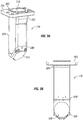
- FIGs. 3A and 3B illustrate the end piece 170.
- FIG. 3A illustrates an isometric view of the end piece 170
- FIG. 3B illustrates a front view of the end piece 170.
- the end piece 170 may be any suitable size, height, shape, and configurations thereof.
- the end piece 170 may comprise a body 300, an attachment flange 305, a central bore 310, a second mirror 315, and an outlet 320.
- the body 300 may generally have a square or rectangular cross-sectional shape.
- the body 300 may have varying dimensions along the length of the body 300.
- the attachment flange 305 may be disposed at a first end 325 of the body 300.
- the attachment flange 305 may be configured to be coupled to the base 185 (referring to FIG. 1 ) of the fastening structure 180 (referring to FIG. 1 ).
- the attachment flange 305 may be any suitable size, height, shape, and combinations thereof. Without limitations, the attachment flange 305 may have a square or rectangular cross-sectional shape.
- the central bore 310 may be accessible at the attachment flange 305 and at the outlet 320.
- the central bore 310 may be any suitable size, shape, length, and combinations thereof.
- the length of the central bore 310 may be the same as the combined length of the body 300 and the thickness of the attachment flange 305.
- the central bore 310 may be uniformly circular throughout its entire length. Without limitations, the central bore 310 may have a diameter that is about 3/16 inches, about 1/4 inches, about 5/16 inches, about 3/8 inches, or any other suitable standard increment.
- the second mirror 315 may be disposed at a second end 330 of the body 300, wherein the second end 330 is opposite to the first end 325. In one or more embodiments, the second mirror 315 may be disposed at any suitable angle. Without limitations, the second mirror 315 may be disposed at an angle of about 45 degrees in relation to the central axis of the body 300. During operations, a light path may travel through the central bore 310 of the body 300. In these embodiments, the second mirror 315 may be configured to direct the light path out of the central bore 310 and through the outlet 320 at an angle in relation to the central axis of the body 300.
- the directed light path may exit the outlet 320 perpendicular to the central axis of the body 300.
- the outlet 320 may be any suitable size and/or shape.
- the outlet 320 may be an opening of the body 300 configured to allow access to the central bore 310.
- the vacuum bore 335 may be configured to communicatively couple the secondary vacuum connector 235 (referring to FIG. 2 ) to the second end 330 of the body 300.
- the vacuum bore 335 may be configured to communicatively couple the secondary vacuum connector 235 (referring to FIG. 2 ) to the second end 330 of the body 300.
- a means of vacuuming may be applied to the desired area to remove the particulates.
- a means of vacuuming may draw the particulates into the vacuum bore 335 through a vacuum port 340 disposed about the second end 330 of the body 300.
- the vacuum port 340 may be an opening configured to allow access to the vacuum bore 335
- An operator may utilize the automated laser system 100 to remove a portion of coatings present on one or more panels prior to nutplate installation.
- the automated laser system 100 may be used to remove a portion of the coatings present around a plurality of predrilled holes.
- the automated laser system 100 may index the plurality of predrilled holes.
- the automated laser system 100 may utilized pre-programmed routes and/or locations for each of the one or more panels via the external controller.
- the automated laser system 100 may be disposed near one of the plurality of predrilled holes.
- the automated laser system 100 may determine the center of the one of the plurality of predrilled holes based on the pre-programmed instructions of the external controller.
- the automated laser system 100 may measure any offsets in the X & Y axes of the actual center in relation to the center determined by the pre-programmed instructions.
- the external controller may instruct the robotic arm, the automated laser system 100, or both to re-adjust so that the automated laser system 100 is within the allowable tolerance.
- the allowable tolerance may be from about 0.1 mm to about 4 mm.
- the third internal mirror 210 may be in the initial position within the light path of the first internal mirror 200 and/or the second internal mirror 205.
- the actual center and measured offsets may be determined by utilizing the camera system 145 and the light source 150.
- the automated laser system 100 may be actuated to operate the laser scanner 105.
- the laser scanner 105 may be actuated to direct a laser that will travel along a light path through the automated laser system 100 and out of the end piece 170.
- the laser scanner 105 may operate at a frequency of about 100 kHz.
- the third internal mirror 210 may be actuated to translate to the secondary position, thereby providing access between the bore 230 and the perpendicular bore of the fastening structure 180.
- the laser may travel along a light path from the laser scanner 105, through the core 230, through the perpendicular bore of the fastening structure 180, deflected by the first mirror 165 to travel through the central bore 310 of the end piece 170, and deflected by the second mirror 315 to travel out through the outlet 320 of the end piece 170.
- a means of vacuuming may be operating as well.
- the means of vacuuming may operate concurrently with, prior to, subsequent to, and combinations thereof of the actuation of the laser scanner 105.
- the means of vacuuming may remove any particulates generated by such operation.
- the automated laser system 100 may perform an optical inspection of the cleaned surface area.
- the third internal mirror 210 may be actuated to translate back to the initial position in order to use the camera system 145 and the light source 150 to inspect the surface area near the outlet 320 of the end piece 170. If the automated laser system 100 determines that the surface area is acceptably clean, the automated laser system 100 may move on to the next one of the plurality of predrilled holes and repeat the process. If the automated laser system 100 determines that the surface area is not acceptably clean, the automated laser system 100 may perform a secondary operation to remove remaining coatings by repeating the previously disclosed methodology above.
- the automated laser system 100 described herein may reduce the amount of scrap, rework, and repair associated with disbonding nutplates.
- the automated laser system 100 may reduce the amount of time needed for installation in comparison to manual techniques.
- references in the appended claims to an apparatus or system or a component of an apparatus or system being adapted to, arranged to, capable of, configured to, enabled to, operable to, or operative to perform a particular function encompasses that apparatus, system, component, whether or not it or that particular function is activated, turned on, or unlocked, as long as that apparatus, system, or component is so adapted, arranged, capable, configured, enabled, operable, or operative. Additionally, although this disclosure describes or illustrates particular embodiments as providing particular advantages, particular embodiments may provide none, some, or all of these advantages.
Landscapes
- Engineering & Computer Science (AREA)
- Physics & Mathematics (AREA)
- Optics & Photonics (AREA)
- Plasma & Fusion (AREA)
- Mechanical Engineering (AREA)
- Laser Beam Processing (AREA)
- Powder Metallurgy (AREA)
- Mechanical Optical Scanning Systems (AREA)
Abstract
Description
- The present application claims priority to
U.S. Application No. 62/941,265, filed on November 27, 2019 - This disclosure generally relates to surface coatings, and more specifically to an automated system for cleaning one or more sections of understructure for the application of nutplates.
- Coatings of various types may be applied to surfaces of structures and vehicles to alter or enhance properties of respective surfaces. For example, some coatings may be applied to provide a weather-resistant layer to protect the underlaying structure. As another example, a coating may be applied to reduce vibrations or other deleterious effects during operation of an aircraft.
- These coatings may be applied to one or more panels prior to installing said panels to the aircraft. Typically, there are predrilled holes in the one or more panels for fastener installation. In order to maximize efficiency, the coatings have been applied first over the one or more panels. A later manufacturing step is to install a plurality of nutplates onto the one or more sections of understructure so as to fasten down the one or more panels to the aircraft. Before installing the plurality of nutplates, the coatings applied to the one or more sections of understructure have to be removed around the area where the plurality of nutplates are to be installed so as to provide better bonding strength for a given adhesive to be used to couple the plurality of nutplates to the one or more sections of understructure. There exists a problem wherein manual surface preparation methods lead to variations in bonding strength of the adhesive, resulting in disbonded nutplates.
- To assist in understanding the present disclosure, reference is now made to the following description taken in conjunction with the accompanying drawings, in which:
-
FIG. 1 illustrates an example automated laser system, according to certain embodiments; -
FIG. 2 illustrates an isometric cross-section of a containment unit of the automated laser system inFIG. 1 , according to certain embodiments; -
FIG. 3A illustrates an example end piece, according to certain embodiments; and -
FIG. 3B illustrates the end piece inFIG. 3A at a front view, according to certain embodiments. - To facilitate a better understanding of the present disclosure, the following examples of certain embodiments are given. The following examples are not to be read to limit or define the scope of the disclosure. Embodiments of the present disclosure and its advantages are best understood by referring to
FIGs. 1 through 3B , where like numbers are used to indicate like and corresponding parts. - As described, surface coatings may be applied onto one or more panels prior to installing the one or more panels onto an aircraft. It may be difficult to accurately remove a portion of the coatings prior to coupling the plurality of nutplates used in fastening the one or more panels to the aircraft. Described herein are various systems and methods that provide an improvement in surface preparation of the one or more panels by using an automated laser system.
-
FIG. 1 illustrates an isometric view of anautomated laser system 100. Theautomated laser system 100 may be configured to produce and direct a laser onto a surface of one or more sections of understructure to remove at least a portion of a coating disposed on the surface of the one or more sections of understructure. In one or more embodiments, theautomated laser system 100 may be coupled to an external actuator configured to move theautomated laser system 100 to numerous locations. Without limitations, theautomated laser system 100 may be coupled to a robotic arm capable of movement about six separate axes. In those embodiments, movement of theautomated laser system 100 about the robotic arm may be pre-programmed into a controller. In one or more embodiments, theautomated laser system 100 may comprise alaser scanner 105, one ormore cables 110, and alaser head 115. In embodiments, thelaser scanner 105 may be configured to direct a laser through theautomated laser system 100. Without limitations, the laser may be configured to operate in a predefined scanning pattern. In embodiments, thelaser scanner 105 may be any suitable size, height, shape, and combinations thereof. Thelaser scanner 105 may comprise one or more galvanometer scanning mirrors. As illustrated thelaser scanner 105 may be communicatively coupled to an external controller and/or a laser source via the one ormore cables 110. In embodiments, the one ormore cables 110 may be any suitable electrical cabling. Without limitations, the one ormore cables 110 may be coaxial cable, communications cable, metallic sheathed cable, non-metallic sheathed cable, fiber optic cable, and combinations thereof. In embodiments, the one ormore cables 110 may comprise at least one communications cable and at least one fiber optic cable. During operations the external controller may control the movement and operation of theautomated laser system 100. In one or more embodiments, the external controller may include one or more interface(s), processing circuitry, memory(ies), and/or other suitable element(s). Interface receives input, sends output, processes the input and/or output, and/or performs other suitable operation. Interface may comprise hardware and/or software. In further embodiments, the laser source may be disposed external to thelaser scanner 105, and it may transmit a laser to thelaser scanner 105 via the one ormore cables 110. - Processing circuitry performs or manages the operations of the component. Processing circuitry may include hardware and/or software. Examples of a processing circuitry include one or more computers, one or more microprocessors, one or more applications, etc. In certain embodiments, processing circuitry executes logic (e.g., instructions) to perform actions (e.g., operations), such as generating output from input. The logic executed by processing circuitry may be encoded in one or more tangible, non-transitory computer readable media (such as memory). For example, the logic may comprise a computer program, software, computer executable instructions, and/or instructions capable of being executed by a computer. In particular embodiments, the operations of the embodiments may be performed by one or more computer readable media storing, embodied with, and/or encoded with a computer program and/or having a stored and/or an encoded computer program.
- Memory (or memory unit) stores information. Memory may comprise one or more non-transitory, tangible, computer-readable, and/or computer-executable storage media. Examples of memory include computer memory (for example, RAM or ROM), mass storage media (for example, a hard disk), removable storage media (for example, a Compact Disk (CD) or a Digital Video Disk (DVD)), database and/or network storage (for example, a server), and/or other computer-readable medium.
- Herein, a computer-readable non-transitory storage medium or media may include one or more semiconductor-based or other integrated circuits (ICs) (such field-programmable gate arrays (FPGAs) or application-specific ICs (ASICs)), hard disk drives (HDDs), hybrid hard drives (HHDs), optical discs, optical disc drives (ODDs), magneto-optical discs, magneto-optical drives, floppy diskettes, floppy disk drives (FDDs), magnetic tapes, solid-state drives (SSDs), RAM-drives, SECURE DIGITAL cards or drives, any other suitable computer-readable non-transitory storage media, or any suitable combination of two or more of these, where appropriate. A computer-readable non-transitory storage medium may be volatile, non-volatile, or a combination of volatile and non-volatile, where appropriate.
- As further illustrated in
FIG. 1 , thelaser scanner 105 may be coupled to thelaser head 115 through aflange 120. As shown, acircular connector 125 may extend from a generallyrectangular base 130 of thelaser scanner 105. In one or more embodiments, theflange 120 may be disposed about thelaser head 115 and may couple thelaser head 115 to thelaser scanner 105 by being affixed to theconnector 125. In one or more embodiments, theflange 120 may be disposed about an end of aconduit 128, wherein an opposing end of the conduit may be disposed about thelaser head 115. In embodiments, thelaser head 115 may be configured to direct the produced laser from thelaser scanner 105 towards a desired, pre-determined location, wherein the produced laser travels along a light path within theconduit 128. In embodiments, thelaser head 115 may be any suitable size, height, shape, and combinations thereof. Thelaser head 115 may comprise acontainment unit 135, avacuum connector 140, acamera system 145, alight source 150, afirst actuator 155, asecond actuator 160, afirst mirror 165, and anend piece 170. Thecontainment unit 135 may be any suitable size, height, shape, and combinations thereof. In embodiments, thecontainment unit 135 may contain a plurality of internal components (described later inFIG. 3 ). As illustrated, the remaining components of thelaser head 115 may be disposed about thecontainment unit 135. - For example, the
vacuum connector 140 may be disposed about afirst side 172 of thecontainment unit 135. In other embodiments, thevacuum connector 140 may be disposed about any other suitable location of thecontainment unit 135. In embodiments, thevacuum connector 140 may be configured to clean the interior of thecontainment unit 135 by providing a means of removing particulates. In one or more embodiments, thevacuum connector 140 may be coupled to a means for vacuuming about an end of thevacuum connector 140. The opposing end of thevacuum connector 140 may be fluidly coupled to the interior of thecontainment unit 135. During operations, thevacuum connector 140 may provide for the removal of any suitable particulates, fluids, and combinations thereof within thecontainment unit 135. - In one or more embodiments, the
camera system 145 and thelight source 150 may be disposed about atop surface 173 of thecontainment unit 135. In other embodiments, thecamera system 145 and thelight source 150 may be disposed about any other suitable location of thecontainment unit 135. In embodiments, any suitable camera system and light source may be used as the disclosedcamera system 145 and thelight source 150. Thecamera system 145 and/or thelight source 150 may be communicatively coupled to the external controller and may be actuated by the external controller. Thecamera system 145 may be configured to capture an image through theend piece 170. Thelight source 150 may be configured to provide a light that is to be directed out of theend piece 170. Without limitations, the light produced may be a blue light or any other suitable color of light. - In one or more embodiments, the
first actuator 155 and thesecond actuator 160 may be disposed about thetop surface 173 of thecontainment unit 135 in addition to thecamera system 145 and thelight source 150. In other embodiments, thefirst actuator 155 and thesecond actuator 160 may be disposed about any other suitable location of thecontainment unit 135. Thefirst actuator 155 may be configured to displace an internal component within the containment unit 135 (i.e., thirdinternal mirror 210 inFIG. 2 ). Thesecond actuator 160 may be configured to displace theend piece 170. In one or more embodiments, thefirst actuator 155 and thesecond actuator 160 may be linear actuators capable of displacing an object along a singular axis (for example, along a vertical direction). In one or more embodiments, thefirst actuator 155 and thesecond actuator 160 may be the same type of actuators. In alternate embodiments, thefirst actuator 155 and thesecond actuator 160 may be different types of actuators. - As illustrated, the
second actuator 160 may displace theend piece 170 via alinkage 175. In embodiments, theend piece 170 may be coupled to afastening structure 180. Thefastening structure 180 may be coupled to an end of thelinkage 175. The opposing end of thelinkage 175 may be coupled to thesecond actuator 160. In embodiments, thelinkage 175 and thefastening structure 180 may be any suitable size, height, shape, and combinations thereof. In embodiments, thefastening structure 180 may comprise any suitable fasteners such as, but not limited to, nuts, bolts, screws, pins, washers, clamps, clips, retaining rings, and combinations thereof. As illustrated, thefastening structure 180 may comprise abase 185 and thefirst mirror 165. The base 185 may be any suitable size, height, shape, and combinations thereof. In embodiments, thebase 185 may be coupled to theend piece 170 via guide pins and/or other suitable fasteners. In embodiments, thebase 185 may comprise an internal bore (not shown) that is concentric to the internal bore of the end piece 170 (described further in FIG. 4A). The internal bore of the base 185 may be coupled to a perpendicular bore of the fastening structure 180 (not shown) through thefirst mirror 165. In one or more embodiments, thefirst mirror 165 may be disposed on top of the base 185 at a suitable angle. Without limitations, thefirst mirror 165 may be disposed on top of the base 185 at an angle of about 45 degrees in relation to the bottom of thebase 185. The disposition of thefirst mirror 165 may be configured to direct a light path (for example, from thelaser scanner 105, thecamera system 145, thelight source 150, and combinations thereof) through thefastening structure 180 to thebase 185 and subsequently to theend piece 170. -
FIG. 2 illustrates an isometric view of an interior of thecontainment unit 135. As illustrated, there may be a firstinternal mirror 200, a secondinternal mirror 205, and a thirdinternal mirror 210 disposed within the interior of thecontainment unit 135. The firstinternal mirror 200 may be disposed within a light path produced by thecamera system 145 and on abottom side 215 of thecontainment unit 135. The secondinternal mirror 205 may be disposed within a light path produced by thelight source 150 and on thebottom side 215 of thecontainment unit 135. In one or more embodiments, the thirdinternal mirror 210 may be disposed within a light path directed by the firstinternal mirror 200 and/or the secondinternal mirror 205. The thirdinternal mirror 210 may disposed about a portion of thefirst actuator 155, wherein thefirst actuator 155 is configured to displace the thirdinternal mirror 210 into and out of the light path directed by the firstinternal mirror 200 and/or the secondinternal mirror 205. In one or more embodiments, thefirst actuator 155 may displace the thirdinternal mirror 210 vertically into and/or out of the light path directed by the firstinternal mirror 200 and/or the secondinternal mirror 205 through execution of the external controller. - In one or more embodiments, the first
internal mirror 200, the secondinternal mirror 205, and the thirdinternal mirror 210 may be disposed at any suitable angle. Without limitations, the firstinternal mirror 200 and the secondinternal mirror 205 may be disposed at an angle of about 45 degrees in relation to thebottom surface 215 of thecontainment unit 135. Without limitations, the thirdinternal mirror 210 may be disposed at an angle of about 45 degrees in relation to asecond side 220 of thecontainment unit 135, wherein thesecond side 220 is opposite to the first side 172 (referring toFIG. 1 ). In one or more embodiments, the firstinternal mirror 200 and the secondinternal mirror 205 may be disposed so as to direct light paths towards the thirdinternal mirror 210. In one or more embodiments, the thirdinternal mirror 210 may be angled so as to direct an incoming light path perpendicularly away from thecontainment unit 135, wherein the light path may be directed in a direction opposite to the direction of the laser scanner 105 (referring toFIG. 1 ). During operations, the thirdinternal mirror 210 may translate vertically along arail 225 of thefirst actuator 155 disposed against the internal side of thesecond side 220. - As further illustrated, the conduit 128 (referring to
FIG. 1 ) may be communicatively coupled to the interior of thecontainment unit 135. A light path travelling along abore 230 within theconduit 128 may be concentric to the perpendicular bore of the fastening structure 180 (referring toFIG. 1 ). In one or more embodiments, the thirdinternal mirror 210 may be in an initial position within the light path of the firstinternal mirror 200 and/or the secondinternal mirror 205. In the initial position, the thirdinternal mirror 210 may block thebore 230 from the perpendicular bore of thefastening structure 180. During operation, thefirst actuator 155 may be actuated to displace the thirdinternal mirror 210 from the initial position to a secondary position. In embodiments, there may be a vertical offset between the initial position and the secondary position, thereby providing an open space between thebore 230 and the perpendicular bore of thefastening structure 180. -
FIG. 2 further illustrates asecondary vacuum connector 235. Thesecondary vacuum connector 235 may be disposed below thecontainment unit 135. Afirst end 240 of thesecondary vacuum connector 235 may be coupled to the base 185 (referring toFIG. 1 ) of thefastening structure 180. In one or more embodiments, aninternal bore 245 of thesecondary vacuum connector 235 may be communicatively coupled to the end piece 170 (referring toFIG. 1 ). In embodiments, an opposing end to thefirst end 240 may be coupled to a means for vacuuming. During operations, thesecondary vacuum connector 235 may be configured to remove any particulates about an end of theend piece 170. -
FIGs. 3A and 3B illustrate theend piece 170.FIG. 3A illustrates an isometric view of theend piece 170, andFIG. 3B illustrates a front view of theend piece 170. Theend piece 170 may be any suitable size, height, shape, and configurations thereof. As illustrated, theend piece 170 may comprise abody 300, anattachment flange 305, acentral bore 310, asecond mirror 315, and anoutlet 320. In embodiments, thebody 300 may generally have a square or rectangular cross-sectional shape. In some embodiments, thebody 300 may have varying dimensions along the length of thebody 300. Theattachment flange 305 may be disposed at afirst end 325 of thebody 300. Theattachment flange 305 may be configured to be coupled to the base 185 (referring toFIG. 1 ) of the fastening structure 180 (referring toFIG. 1 ). In embodiments, theattachment flange 305 may be any suitable size, height, shape, and combinations thereof. Without limitations, theattachment flange 305 may have a square or rectangular cross-sectional shape. - In embodiments, the
central bore 310 may be accessible at theattachment flange 305 and at theoutlet 320. Thecentral bore 310 may be any suitable size, shape, length, and combinations thereof. In embodiments, the length of thecentral bore 310 may be the same as the combined length of thebody 300 and the thickness of theattachment flange 305. In one or more embodiments, thecentral bore 310 may be uniformly circular throughout its entire length. Without limitations, thecentral bore 310 may have a diameter that is about 3/16 inches, about 1/4 inches, about 5/16 inches, about 3/8 inches, or any other suitable standard increment. - In one or more embodiments, the
second mirror 315 may be disposed at asecond end 330 of thebody 300, wherein thesecond end 330 is opposite to thefirst end 325. In one or more embodiments, thesecond mirror 315 may be disposed at any suitable angle. Without limitations, thesecond mirror 315 may be disposed at an angle of about 45 degrees in relation to the central axis of thebody 300. During operations, a light path may travel through thecentral bore 310 of thebody 300. In these embodiments, thesecond mirror 315 may be configured to direct the light path out of thecentral bore 310 and through theoutlet 320 at an angle in relation to the central axis of thebody 300. Without limitations, the directed light path may exit theoutlet 320 perpendicular to the central axis of thebody 300. In embodiments, theoutlet 320 may be any suitable size and/or shape. Theoutlet 320 may be an opening of thebody 300 configured to allow access to thecentral bore 310. - As illustrated, there may be a
vacuum bore 335 disposed within thebody 300. The vacuum bore 335 may be configured to communicatively couple the secondary vacuum connector 235 (referring toFIG. 2 ) to thesecond end 330 of thebody 300. During operations, as the laser head 115 (referring toFIG. 1 ) operates, particulates of coatings previously applied to the one or more panels may be generated. As the particulates are produced, a means of vacuuming may be applied to the desired area to remove the particulates. In one or more embodiments, a means of vacuuming may draw the particulates into the vacuum bore 335 through avacuum port 340 disposed about thesecond end 330 of thebody 300. In embodiments, thevacuum port 340 may be an opening configured to allow access to the vacuum bore 335 - With reference to
FIGs. 1-3B , the method as presented in the present disclosure may be described. An operator may utilize theautomated laser system 100 to remove a portion of coatings present on one or more panels prior to nutplate installation. Specifically, theautomated laser system 100 may be used to remove a portion of the coatings present around a plurality of predrilled holes. - Initially, the
automated laser system 100 may index the plurality of predrilled holes. Theautomated laser system 100 may utilized pre-programmed routes and/or locations for each of the one or more panels via the external controller. In embodiments, theautomated laser system 100 may be disposed near one of the plurality of predrilled holes. Theautomated laser system 100 may determine the center of the one of the plurality of predrilled holes based on the pre-programmed instructions of the external controller. Theautomated laser system 100 may measure any offsets in the X & Y axes of the actual center in relation to the center determined by the pre-programmed instructions. In embodiments, if the actual center is outside of an allowable tolerance, the external controller may instruct the robotic arm, theautomated laser system 100, or both to re-adjust so that theautomated laser system 100 is within the allowable tolerance. Without limitations, the allowable tolerance may be from about 0.1 mm to about 4 mm. In these embodiments, the thirdinternal mirror 210 may be in the initial position within the light path of the firstinternal mirror 200 and/or the secondinternal mirror 205. The actual center and measured offsets may be determined by utilizing thecamera system 145 and thelight source 150. In embodiments, if the actual center is within an allowable tolerance, theautomated laser system 100 may be actuated to operate thelaser scanner 105. - During operations, the
laser scanner 105 may be actuated to direct a laser that will travel along a light path through theautomated laser system 100 and out of theend piece 170. In one or more embodiments, thelaser scanner 105 may operate at a frequency of about 100 kHz. Prior to actuating thelaser scanner 105, the thirdinternal mirror 210 may be actuated to translate to the secondary position, thereby providing access between thebore 230 and the perpendicular bore of thefastening structure 180. In embodiments, the laser may travel along a light path from thelaser scanner 105, through thecore 230, through the perpendicular bore of thefastening structure 180, deflected by thefirst mirror 165 to travel through thecentral bore 310 of theend piece 170, and deflected by thesecond mirror 315 to travel out through theoutlet 320 of theend piece 170. - As the
automated laser system 100 operates, a means of vacuuming may be operating as well. In embodiments, the means of vacuuming may operate concurrently with, prior to, subsequent to, and combinations thereof of the actuation of thelaser scanner 105. As the laser produced by thelaser scanner 105 removes at least a portion of the coatings disposed on the one or more panels around the plurality of predrilled holes, the means of vacuuming may remove any particulates generated by such operation. - Upon completion of the actuation of the
laser scanner 105, theautomated laser system 100 may perform an optical inspection of the cleaned surface area. In these embodiments, the thirdinternal mirror 210 may be actuated to translate back to the initial position in order to use thecamera system 145 and thelight source 150 to inspect the surface area near theoutlet 320 of theend piece 170. If theautomated laser system 100 determines that the surface area is acceptably clean, theautomated laser system 100 may move on to the next one of the plurality of predrilled holes and repeat the process. If theautomated laser system 100 determines that the surface area is not acceptably clean, theautomated laser system 100 may perform a secondary operation to remove remaining coatings by repeating the previously disclosed methodology above. - Technical advantages of this disclosure may include one or more of the following. The
automated laser system 100 described herein may reduce the amount of scrap, rework, and repair associated with disbonding nutplates. Theautomated laser system 100 may reduce the amount of time needed for installation in comparison to manual techniques. - The present disclosure may provide numerous advantages, such as the various technical advantages that have been described with respective to various embodiments and examples disclosed herein. Other technical advantages will be readily apparent to one skilled in the art from the following figures, descriptions, and claims. Moreover, while specific advantages have been enumerated in this disclosure, various embodiments may include all, some, or none of the enumerated advantages.
- Herein, "or" is inclusive and not exclusive, unless expressly indicated otherwise or indicated otherwise by context. Therefore, herein, "A or B" means "A, B, or both," unless expressly indicated otherwise or indicated otherwise by context. Moreover, "and" is both joint and several, unless expressly indicated otherwise or indicated otherwise by context. Therefore, herein, "A and B" means "A and B, jointly or severally," unless expressly indicated otherwise or indicated otherwise by context.
- The scope of this disclosure encompasses all changes, substitutions, variations, alterations, and modifications to the example embodiments described or illustrated herein that a person having ordinary skill in the art would comprehend. The scope of this disclosure is not limited to the example embodiments described or illustrated herein. Moreover, although this disclosure describes and illustrates respective embodiments herein as including particular components, elements, feature, functions, operations, or steps, any of these embodiments may include any combination or permutation of any of the components, elements, features, functions, operations, or steps described or illustrated anywhere herein that a person having ordinary skill in the art would comprehend. Furthermore, reference in the appended claims to an apparatus or system or a component of an apparatus or system being adapted to, arranged to, capable of, configured to, enabled to, operable to, or operative to perform a particular function encompasses that apparatus, system, component, whether or not it or that particular function is activated, turned on, or unlocked, as long as that apparatus, system, or component is so adapted, arranged, capable, configured, enabled, operable, or operative. Additionally, although this disclosure describes or illustrates particular embodiments as providing particular advantages, particular embodiments may provide none, some, or all of these advantages.
Claims (15)
- An automated laser system, comprising:a laser scanner; anda laser head, wherein the laser head is coupled to the laser scanner, wherein the laser head comprises:a containment unit;a vacuum connector, wherein the vacuum connector is disposed on a first side of the containment unit;a camera system, wherein the camera system is disposed on a top surface of the containment unit;a light source, wherein the light source is disposed on the top surface of the containment unit;a first actuator, wherein the first actuator is disposed on the top surface of the containment unit;a second actuator, wherein the second actuator is disposed on the top surface of the containment unit, wherein the light source is disposed between the camera system and the second actuator, wherein the second actuator is disposed between the light source and the first actuator; andan end piece, wherein the second actuator is configured to displace the end piece.
- The automated laser system of claim 1, wherein a laser source and an external controller are communicatively coupled to the laser scanner via one or more cables, and optionally or preferably, wherein the one or more cables comprise a fiber optic cable and a communications cable.
- The automated laser system of claim 1 or of claim 2, wherein the automated laser system is coupled to a robotic arm capable of movement about six separate axes.
- The automated laser system of claim 1 or of claim 2 or of claim 3, wherein the end piece is coupled to a fastening structure, wherein the fastening structure is coupled to an end of a linkage, wherein an opposing end of the linkage is coupled to the second actuator.
- The automated laser system of claim 4, wherein the fastening structure comprises a base, a first mirror, and a perpendicular bore, and optionally or preferably, wherein the first mirror is disposed on top of the base, wherein the base comprises an internal bore, and optionally or preferably, wherein the internal bore and the perpendicular bore are communicatively coupled.
- A laser head, comprising:a containment unit, wherein the containment unit comprises a first internal mirror, a second internal mirror, and a third internal mirror;a vacuum connector, wherein the vacuum connector is disposed on a first side of the containment unit;a secondary vacuum connector, wherein the secondary vacuum connector is disposed below the containment unit;a camera system, wherein the camera system is disposed on a top surface of the containment unit;a light source, wherein the light source is disposed on the top surface of the containment unit;a first actuator, wherein the first actuator is disposed on the top surface of the containment unit;a second actuator, wherein the second actuator is disposed on the top surface of the containment unit, wherein the light source is disposed between the camera system and the second actuator, wherein the second actuator is disposed between the light source and the first actuator; andan end piece, wherein the second actuator is configured to displace the end piece, wherein the end piece is coupled to a fastening structure, wherein the fastening structure is coupled to an end of a linkage, wherein an opposing end of the linkage is coupled to the second actuator.
- The laser head of claim 6, wherein the fastening structure comprises a base, a first mirror, and a perpendicular bore, wherein the first mirror is disposed on top of the base, wherein the base comprises an internal bore, wherein the internal bore and the perpendicular bore are communicatively coupled.
- The automated laser system of claim 1 or of any of claims 2 to 5, or the laser head of claim 6 or claim 7 , wherein the end piece comprises a body, an attachment flange, a central bore, a second mirror, an outlet, a vacuum bore, and a vacuum port.
- The automated laser system of claim 6 or the laser head of claim 7, wherein the attachment flange is disposed at a first end of the body, wherein the second mirror and the outlet are disposed at a second end of the body; or
the laser head of claim 7, wherein the end piece comprises a body, an attachment flange, a central bore, a second mirror, an outlet, a vacuum bore, and a vacuum port, wherein the attachment flange is disposed at a first end of the body, wherein the second mirror and the outlet are disposed at a second end of the body, wherein the attachment flange is coupled to the base, wherein the internal bore of the base is concentric to the central bore. - The automated laser system of claim 8 or of claim 9, wherein the central bore has a diameter of 3/16 inches, 1/4 inches, 5/16 inches, or 3/8 inches.
- The automated laser system of claim 1 or of any preceding claim, or the laser head of claim 6 or of any preceding claim, wherein the containment unit comprises a first internal mirror, a second internal mirror, a third internal mirror, and a rail.
- The automated laser system or laser head of claim 11, wherein(i) the first internal mirror is disposed within a light path produced by the camera system and on a bottom side of the containment unit, wherein the second internal mirror is disposed within a light path produced by the light source and on the bottom side of the containment unit; and/or(ii) the third internal mirror is disposed onto the rail of the first actuator, wherein the first actuator is configured to translate the third internal mirror, wherein the rail is disposed on an internal side of a second side of the containment unit.
- A method of cleaning a surface area of one or more panels for nutplates installation, comprising:disposing an automated laser system about one of a plurality of predrilled holes of the one or more panels;determining a center of the one of the plurality of predrilled holes by pre-programmed instructions from an external controller;measuring an offset in the X & Y axes of an actual center in relation to the center determined by the pre-programmed instructions; andactuating the automated laser system to produce a laser to remove a portion of a coating disposed on the one or more panels.
- The method of claim 13, further comprising:-(i) actuating a first actuator to displace a third internal mirror from an initial position to a secondary position; and/or(ii) actuating a means of vacuuming concurrently with actuating the automated laser system.
- The laser head of claim 6, wherein the first internal mirror is disposed within a light path produced by the camera system and on a bottom side of the containment unit, wherein the second internal mirror is disposed within a light path produced by the light source and on the bottom side of the containment unit, wherein the third internal mirror is disposed onto a rail of the first actuator, wherein the first actuator is configured to translate the third internal mirror, wherein the rail is disposed on an internal side of a second side of the containment unit.
Applications Claiming Priority (2)
| Application Number | Priority Date | Filing Date | Title |
|---|---|---|---|
| US201962941265P | 2019-11-27 | 2019-11-27 | |
| US16/777,296 US11173526B2 (en) | 2019-11-27 | 2020-01-30 | Automated structural laser cleaning system |
Publications (2)
| Publication Number | Publication Date |
|---|---|
| EP3871824A1 true EP3871824A1 (en) | 2021-09-01 |
| EP3871824B1 EP3871824B1 (en) | 2022-12-28 |
Family
ID=75971397
Family Applications (1)
| Application Number | Title | Priority Date | Filing Date |
|---|---|---|---|
| EP20199053.8A Active EP3871824B1 (en) | 2019-11-27 | 2020-09-29 | Automated structural laser cleaning system |
Country Status (5)
| Country | Link |
|---|---|
| US (2) | US11173526B2 (en) |
| EP (1) | EP3871824B1 (en) |
| JP (1) | JP7369680B2 (en) |
| KR (1) | KR102444027B1 (en) |
| AU (2) | AU2020239671B2 (en) |
Families Citing this family (2)
| Publication number | Priority date | Publication date | Assignee | Title |
|---|---|---|---|---|
| BE1028012B1 (en) * | 2020-01-27 | 2021-08-24 | Netalux Nv | LASER TREATMENT DEVICE AND METHOD FOR LASER TREATMENT |
| WO2024174021A1 (en) * | 2023-02-20 | 2024-08-29 | Magna International Inc. | System and method for de-coating components with a laser |
Citations (4)
| Publication number | Priority date | Publication date | Assignee | Title |
|---|---|---|---|---|
| DE20209305U1 (en) * | 2001-06-13 | 2002-08-29 | LST Laser & Strahl Technik Herstellungs- und Handelsgesellschaft m.b.H., Wien | Device for supplying a laser beam to a working point that is freely movable in space |
| US20070000885A1 (en) * | 2004-01-09 | 2007-01-04 | General Lasertronics Corporation | Color sensing for laser decoating |
| WO2013141810A1 (en) * | 2012-03-21 | 2013-09-26 | Ngee Ann Polytechnic | A laser cleaning apparatus and method |
| US20190275568A1 (en) * | 2017-01-03 | 2019-09-12 | The Boeing Company | Large-area selective ablation systems |
Family Cites Families (24)
| Publication number | Priority date | Publication date | Assignee | Title |
|---|---|---|---|---|
| US4978830A (en) * | 1989-02-27 | 1990-12-18 | National Semiconductor Corporation | Laser trimming system for semiconductor integrated circuit chip packages |
| US5782253A (en) | 1991-12-24 | 1998-07-21 | Mcdonnell Douglas Corporation | System for removing a coating from a substrate |
| US5662762A (en) | 1995-07-07 | 1997-09-02 | Clover Industries, Inc. | Laser-based system and method for stripping coatings from substrates |
| US5986234A (en) | 1997-03-28 | 1999-11-16 | The Regents Of The University Of California | High removal rate laser-based coating removal system |
| JPH1128900A (en) * | 1997-05-12 | 1999-02-02 | Sumitomo Heavy Ind Ltd | Paint removal method and laser processing device using laser light |
| GB2330653B (en) | 1997-10-24 | 2002-05-08 | British Aerospace | Process and apparatus for monitoring surface laser cleaning |
| US6369353B1 (en) * | 1998-02-20 | 2002-04-09 | The Goodyear Tire & Rubber Company | Robotic laser tire mold cleaning system and method of use |
| US6288362B1 (en) * | 1998-04-24 | 2001-09-11 | James W. Thomas | Method and apparatus for treating surfaces and ablating surface material |
| US7633033B2 (en) | 2004-01-09 | 2009-12-15 | General Lasertronics Corporation | Color sensing for laser decoating |
| EP1598121A3 (en) | 2004-05-18 | 2007-02-14 | Airbus Deutschland GmbH | Laser-based stripping method |
| US8536483B2 (en) | 2007-03-22 | 2013-09-17 | General Lasertronics Corporation | Methods for stripping and modifying surfaces with laser-induced ablation |
| US10112257B1 (en) | 2010-07-09 | 2018-10-30 | General Lasertronics Corporation | Coating ablating apparatus with coating removal detection |
| JP2012222242A (en) | 2011-04-12 | 2012-11-12 | Panasonic Industrial Devices Sunx Co Ltd | Laser processing device, and laser processing system |
| EP2768627A4 (en) | 2011-10-21 | 2016-01-13 | American Laser Entpr Llc | SYSTEM CONFIGURED TO REMOVE COATING FROM SUBSTRATE USING ELECTROMAGNETIC RADIATION |
| MY173547A (en) * | 2012-10-19 | 2020-02-04 | Ipg Photonics Corp | Robotic laser seam stepper |
| KR101480346B1 (en) * | 2013-10-18 | 2015-01-08 | 주식회사 사이보그-랩 | gravity compensation device of vertical articulated robot with a parallel link structure |
| US9945253B2 (en) | 2015-01-29 | 2018-04-17 | Rohr, Inc. | Collecting / removing byproducts of laser ablation |
| JP6968700B2 (en) * | 2015-05-13 | 2021-11-17 | シェイパー ツールズ, インク.Shaper Tools, Inc. | Systems, methods, and equipment for guide tools |
| US10016792B2 (en) | 2016-10-14 | 2018-07-10 | The Boeing Company | Processing tool cleaning using laser ablation |
| US10737303B2 (en) | 2017-06-23 | 2020-08-11 | Lockheed Martin Corporation | Nutplate preparation laser system |
| US10751766B2 (en) | 2017-11-15 | 2020-08-25 | The Boeing Company | Laser ablation system having a moveable carriage with clamping system configured to clamp and seal against a workpiece |
| JP7020897B2 (en) | 2017-12-14 | 2022-02-16 | 株式会社キーエンス | Laser processing equipment and galvano scanner |
| JP7011523B2 (en) | 2018-04-20 | 2022-01-26 | 住友重機械工業株式会社 | Machining system, welding method |
| US11090765B2 (en) * | 2018-09-25 | 2021-08-17 | Saudi Arabian Oil Company | Laser tool for removing scaling |
-
2020
- 2020-01-30 US US16/777,296 patent/US11173526B2/en active Active
- 2020-09-23 AU AU2020239671A patent/AU2020239671B2/en active Active
- 2020-09-29 EP EP20199053.8A patent/EP3871824B1/en active Active
- 2020-11-04 JP JP2020184226A patent/JP7369680B2/en active Active
- 2020-11-26 KR KR1020200160631A patent/KR102444027B1/en active Active
-
2021
- 2021-10-12 US US17/499,217 patent/US11919052B2/en active Active
-
2024
- 2024-11-13 AU AU2024264595A patent/AU2024264595B2/en active Active
Patent Citations (4)
| Publication number | Priority date | Publication date | Assignee | Title |
|---|---|---|---|---|
| DE20209305U1 (en) * | 2001-06-13 | 2002-08-29 | LST Laser & Strahl Technik Herstellungs- und Handelsgesellschaft m.b.H., Wien | Device for supplying a laser beam to a working point that is freely movable in space |
| US20070000885A1 (en) * | 2004-01-09 | 2007-01-04 | General Lasertronics Corporation | Color sensing for laser decoating |
| WO2013141810A1 (en) * | 2012-03-21 | 2013-09-26 | Ngee Ann Polytechnic | A laser cleaning apparatus and method |
| US20190275568A1 (en) * | 2017-01-03 | 2019-09-12 | The Boeing Company | Large-area selective ablation systems |
Also Published As
| Publication number | Publication date |
|---|---|
| EP3871824B1 (en) | 2022-12-28 |
| JP2021084136A (en) | 2021-06-03 |
| KR20210065873A (en) | 2021-06-04 |
| US20220023921A1 (en) | 2022-01-27 |
| AU2024264595B2 (en) | 2024-12-19 |
| US20210154709A1 (en) | 2021-05-27 |
| KR102444027B1 (en) | 2022-09-15 |
| AU2020239671B2 (en) | 2024-10-10 |
| US11173526B2 (en) | 2021-11-16 |
| JP7369680B2 (en) | 2023-10-26 |
| US11919052B2 (en) | 2024-03-05 |
| AU2024264595A1 (en) | 2024-11-28 |
| AU2020239671A1 (en) | 2021-06-10 |
Similar Documents
| Publication | Publication Date | Title |
|---|---|---|
| AU2024264595B2 (en) | Automated structural laser cleaning system | |
| CN102879479B (en) | Merge nondestructive detection system and the method for interchangeable probe | |
| JP6557299B2 (en) | Pollution identification system | |
| JP5563238B2 (en) | Synchronous robot motion in structures with limited space | |
| US20110260057A1 (en) | Charged particle beam apparatus | |
| CN101911276A (en) | Systems and methods for calibrating end effector alignment using at least one light source | |
| CN101000311A (en) | Defects detection device and method | |
| CN1309598A (en) | Visual tube position verification system | |
| TW201009519A (en) | Charged particle beam lithography system and target positioning device | |
| US20210192708A1 (en) | Three-dimensional inspection of a workpiece for conformance to a specification | |
| US7349165B2 (en) | Clamping apparatus for clamping optical element | |
| CN115248597B (en) | An AGV intelligent parking method serving laser cleaning process | |
| TWI322260B (en) | Image pickup apparatus equipped with a microscope and size measuring apparatus | |
| US11642852B2 (en) | Rotational material scattering additive manufacturing device | |
| US20240210162A1 (en) | Automated Non-Contact Thickness Inspection and Projection System | |
| Zhang et al. | Self‐calibration method for vision‐guided cell micromanipulation systems | |
| US20050060877A1 (en) | System and apparatus for assembling a hard disk drive having a motor bracket tooling hole for inverted motor-to-base merge process | |
| US7117582B2 (en) | Method of assembling a hard disk drive having a motor bracket tooling hole for inverted motor-to-base merge process | |
| Vikramaditya | Micromanipulation using self assembly strategies | |
| JP2005122473A (en) | Fixture of fire sensor | |
| US20170017059A1 (en) | Alignment of an optical component | |
| CN121539452A (en) | A graded intelligent detection system and method for wind power hybrid towers | |
| CN121756569A (en) | Magnetic attraction queue type multi-substrate continuous manufacturing method | |
| Su et al. | Implementation of a Doppler-Free Saturation Spectroscopy (DFSS) diagnostic for helicon wave electric field vector measurement in edge plasma in DIII-D | |
| KR20250162542A (en) | Machine Vision-Based Showerhead Inspection |
Legal Events
| Date | Code | Title | Description |
|---|---|---|---|
| PUAI | Public reference made under article 153(3) epc to a published international application that has entered the european phase |
Free format text: ORIGINAL CODE: 0009012 |
|
| STAA | Information on the status of an ep patent application or granted ep patent |
Free format text: STATUS: THE APPLICATION HAS BEEN PUBLISHED |
|
| AK | Designated contracting states |
Kind code of ref document: A1 Designated state(s): AL AT BE BG CH CY CZ DE DK EE ES FI FR GB GR HR HU IE IS IT LI LT LU LV MC MK MT NL NO PL PT RO RS SE SI SK SM TR |
|
| STAA | Information on the status of an ep patent application or granted ep patent |
Free format text: STATUS: REQUEST FOR EXAMINATION WAS MADE |
|
| 17P | Request for examination filed |
Effective date: 20220301 |
|
| RBV | Designated contracting states (corrected) |
Designated state(s): AL AT BE BG CH CY CZ DE DK EE ES FI FR GB GR HR HU IE IS IT LI LT LU LV MC MK MT NL NO PL PT RO RS SE SI SK SM TR |
|
| GRAP | Despatch of communication of intention to grant a patent |
Free format text: ORIGINAL CODE: EPIDOSNIGR1 |
|
| STAA | Information on the status of an ep patent application or granted ep patent |
Free format text: STATUS: GRANT OF PATENT IS INTENDED |
|
| RIC1 | Information provided on ipc code assigned before grant |
Ipc: B23K 101/34 20060101ALN20220602BHEP Ipc: B23K 101/00 20060101ALN20220602BHEP Ipc: B23K 26/40 20140101ALI20220602BHEP Ipc: B23K 26/362 20140101ALI20220602BHEP Ipc: B23K 26/16 20060101ALI20220602BHEP Ipc: B23K 26/14 20140101ALI20220602BHEP Ipc: B23K 26/082 20140101ALI20220602BHEP Ipc: B23K 26/03 20060101AFI20220602BHEP |
|
| INTG | Intention to grant announced |
Effective date: 20220705 |
|
| RIN1 | Information on inventor provided before grant (corrected) |
Inventor name: ARTHUR, ALEXANDRIA ZOE Inventor name: TWADDLE, STEVEN E. Inventor name: LANGEVIN, JEFFREY P. Inventor name: STODDARD, MICHAEL BRYAN Inventor name: COLEMAN, DAVID HAYNES |
|
| GRAS | Grant fee paid |
Free format text: ORIGINAL CODE: EPIDOSNIGR3 |
|
| GRAA | (expected) grant |
Free format text: ORIGINAL CODE: 0009210 |
|
| STAA | Information on the status of an ep patent application or granted ep patent |
Free format text: STATUS: THE PATENT HAS BEEN GRANTED |
|
| AK | Designated contracting states |
Kind code of ref document: B1 Designated state(s): AL AT BE BG CH CY CZ DE DK EE ES FI FR GB GR HR HU IE IS IT LI LT LU LV MC MK MT NL NO PL PT RO RS SE SI SK SM TR |
|
| REG | Reference to a national code |
Ref country code: GB Ref legal event code: FG4D |
|
| REG | Reference to a national code |
Ref country code: CH Ref legal event code: EP |
|
| REG | Reference to a national code |
Ref country code: DE Ref legal event code: R096 Ref document number: 602020007180 Country of ref document: DE |
|
| REG | Reference to a national code |
Ref country code: AT Ref legal event code: REF Ref document number: 1540142 Country of ref document: AT Kind code of ref document: T Effective date: 20230115 |
|
| REG | Reference to a national code |
Ref country code: IE Ref legal event code: FG4D |
|
| REG | Reference to a national code |
Ref country code: LT Ref legal event code: MG9D |
|
| PG25 | Lapsed in a contracting state [announced via postgrant information from national office to epo] |
Ref country code: SE Free format text: LAPSE BECAUSE OF FAILURE TO SUBMIT A TRANSLATION OF THE DESCRIPTION OR TO PAY THE FEE WITHIN THE PRESCRIBED TIME-LIMIT Effective date: 20221228 Ref country code: NO Free format text: LAPSE BECAUSE OF FAILURE TO SUBMIT A TRANSLATION OF THE DESCRIPTION OR TO PAY THE FEE WITHIN THE PRESCRIBED TIME-LIMIT Effective date: 20230328 Ref country code: LT Free format text: LAPSE BECAUSE OF FAILURE TO SUBMIT A TRANSLATION OF THE DESCRIPTION OR TO PAY THE FEE WITHIN THE PRESCRIBED TIME-LIMIT Effective date: 20221228 Ref country code: FI Free format text: LAPSE BECAUSE OF FAILURE TO SUBMIT A TRANSLATION OF THE DESCRIPTION OR TO PAY THE FEE WITHIN THE PRESCRIBED TIME-LIMIT Effective date: 20221228 |
|
| REG | Reference to a national code |
Ref country code: NL Ref legal event code: MP Effective date: 20221228 |
|
| REG | Reference to a national code |
Ref country code: AT Ref legal event code: MK05 Ref document number: 1540142 Country of ref document: AT Kind code of ref document: T Effective date: 20221228 |
|
| PG25 | Lapsed in a contracting state [announced via postgrant information from national office to epo] |
Ref country code: RS Free format text: LAPSE BECAUSE OF FAILURE TO SUBMIT A TRANSLATION OF THE DESCRIPTION OR TO PAY THE FEE WITHIN THE PRESCRIBED TIME-LIMIT Effective date: 20221228 Ref country code: LV Free format text: LAPSE BECAUSE OF FAILURE TO SUBMIT A TRANSLATION OF THE DESCRIPTION OR TO PAY THE FEE WITHIN THE PRESCRIBED TIME-LIMIT Effective date: 20221228 Ref country code: HR Free format text: LAPSE BECAUSE OF FAILURE TO SUBMIT A TRANSLATION OF THE DESCRIPTION OR TO PAY THE FEE WITHIN THE PRESCRIBED TIME-LIMIT Effective date: 20221228 Ref country code: GR Free format text: LAPSE BECAUSE OF FAILURE TO SUBMIT A TRANSLATION OF THE DESCRIPTION OR TO PAY THE FEE WITHIN THE PRESCRIBED TIME-LIMIT Effective date: 20230329 |
|
| PG25 | Lapsed in a contracting state [announced via postgrant information from national office to epo] |
Ref country code: NL Free format text: LAPSE BECAUSE OF FAILURE TO SUBMIT A TRANSLATION OF THE DESCRIPTION OR TO PAY THE FEE WITHIN THE PRESCRIBED TIME-LIMIT Effective date: 20221228 |
|
| PG25 | Lapsed in a contracting state [announced via postgrant information from national office to epo] |
Ref country code: SM Free format text: LAPSE BECAUSE OF FAILURE TO SUBMIT A TRANSLATION OF THE DESCRIPTION OR TO PAY THE FEE WITHIN THE PRESCRIBED TIME-LIMIT Effective date: 20221228 Ref country code: RO Free format text: LAPSE BECAUSE OF FAILURE TO SUBMIT A TRANSLATION OF THE DESCRIPTION OR TO PAY THE FEE WITHIN THE PRESCRIBED TIME-LIMIT Effective date: 20221228 Ref country code: PT Free format text: LAPSE BECAUSE OF FAILURE TO SUBMIT A TRANSLATION OF THE DESCRIPTION OR TO PAY THE FEE WITHIN THE PRESCRIBED TIME-LIMIT Effective date: 20230428 Ref country code: ES Free format text: LAPSE BECAUSE OF FAILURE TO SUBMIT A TRANSLATION OF THE DESCRIPTION OR TO PAY THE FEE WITHIN THE PRESCRIBED TIME-LIMIT Effective date: 20221228 Ref country code: EE Free format text: LAPSE BECAUSE OF FAILURE TO SUBMIT A TRANSLATION OF THE DESCRIPTION OR TO PAY THE FEE WITHIN THE PRESCRIBED TIME-LIMIT Effective date: 20221228 Ref country code: CZ Free format text: LAPSE BECAUSE OF FAILURE TO SUBMIT A TRANSLATION OF THE DESCRIPTION OR TO PAY THE FEE WITHIN THE PRESCRIBED TIME-LIMIT Effective date: 20221228 Ref country code: AT Free format text: LAPSE BECAUSE OF FAILURE TO SUBMIT A TRANSLATION OF THE DESCRIPTION OR TO PAY THE FEE WITHIN THE PRESCRIBED TIME-LIMIT Effective date: 20221228 |
|
| P01 | Opt-out of the competence of the unified patent court (upc) registered |
Effective date: 20230705 |
|
| PG25 | Lapsed in a contracting state [announced via postgrant information from national office to epo] |
Ref country code: SK Free format text: LAPSE BECAUSE OF FAILURE TO SUBMIT A TRANSLATION OF THE DESCRIPTION OR TO PAY THE FEE WITHIN THE PRESCRIBED TIME-LIMIT Effective date: 20221228 Ref country code: PL Free format text: LAPSE BECAUSE OF FAILURE TO SUBMIT A TRANSLATION OF THE DESCRIPTION OR TO PAY THE FEE WITHIN THE PRESCRIBED TIME-LIMIT Effective date: 20221228 Ref country code: IS Free format text: LAPSE BECAUSE OF FAILURE TO SUBMIT A TRANSLATION OF THE DESCRIPTION OR TO PAY THE FEE WITHIN THE PRESCRIBED TIME-LIMIT Effective date: 20230428 Ref country code: AL Free format text: LAPSE BECAUSE OF FAILURE TO SUBMIT A TRANSLATION OF THE DESCRIPTION OR TO PAY THE FEE WITHIN THE PRESCRIBED TIME-LIMIT Effective date: 20221228 |
|
| REG | Reference to a national code |
Ref country code: DE Ref legal event code: R097 Ref document number: 602020007180 Country of ref document: DE |
|
| PG25 | Lapsed in a contracting state [announced via postgrant information from national office to epo] |
Ref country code: DK Free format text: LAPSE BECAUSE OF FAILURE TO SUBMIT A TRANSLATION OF THE DESCRIPTION OR TO PAY THE FEE WITHIN THE PRESCRIBED TIME-LIMIT Effective date: 20221228 |
|
| PLBE | No opposition filed within time limit |
Free format text: ORIGINAL CODE: 0009261 |
|
| STAA | Information on the status of an ep patent application or granted ep patent |
Free format text: STATUS: NO OPPOSITION FILED WITHIN TIME LIMIT |
|
| 26N | No opposition filed |
Effective date: 20230929 |
|
| PG25 | Lapsed in a contracting state [announced via postgrant information from national office to epo] |
Ref country code: SI Free format text: LAPSE BECAUSE OF FAILURE TO SUBMIT A TRANSLATION OF THE DESCRIPTION OR TO PAY THE FEE WITHIN THE PRESCRIBED TIME-LIMIT Effective date: 20221228 |
|
| REG | Reference to a national code |
Ref country code: CH Ref legal event code: PL |
|
| PG25 | Lapsed in a contracting state [announced via postgrant information from national office to epo] |
Ref country code: LU Free format text: LAPSE BECAUSE OF NON-PAYMENT OF DUE FEES Effective date: 20230929 |
|
| REG | Reference to a national code |
Ref country code: BE Ref legal event code: MM Effective date: 20230930 |
|
| PG25 | Lapsed in a contracting state [announced via postgrant information from national office to epo] |
Ref country code: LU Free format text: LAPSE BECAUSE OF NON-PAYMENT OF DUE FEES Effective date: 20230929 Ref country code: MC Free format text: LAPSE BECAUSE OF FAILURE TO SUBMIT A TRANSLATION OF THE DESCRIPTION OR TO PAY THE FEE WITHIN THE PRESCRIBED TIME-LIMIT Effective date: 20221228 |
|
| REG | Reference to a national code |
Ref country code: IE Ref legal event code: MM4A |
|
| PG25 | Lapsed in a contracting state [announced via postgrant information from national office to epo] |
Ref country code: IE Free format text: LAPSE BECAUSE OF NON-PAYMENT OF DUE FEES Effective date: 20230929 |
|
| PG25 | Lapsed in a contracting state [announced via postgrant information from national office to epo] |
Ref country code: CH Free format text: LAPSE BECAUSE OF NON-PAYMENT OF DUE FEES Effective date: 20230930 |
|
| PG25 | Lapsed in a contracting state [announced via postgrant information from national office to epo] |
Ref country code: IE Free format text: LAPSE BECAUSE OF NON-PAYMENT OF DUE FEES Effective date: 20230929 Ref country code: CH Free format text: LAPSE BECAUSE OF NON-PAYMENT OF DUE FEES Effective date: 20230930 |
|
| PG25 | Lapsed in a contracting state [announced via postgrant information from national office to epo] |
Ref country code: BE Free format text: LAPSE BECAUSE OF NON-PAYMENT OF DUE FEES Effective date: 20230930 |
|
| PG25 | Lapsed in a contracting state [announced via postgrant information from national office to epo] |
Ref country code: BG Free format text: LAPSE BECAUSE OF FAILURE TO SUBMIT A TRANSLATION OF THE DESCRIPTION OR TO PAY THE FEE WITHIN THE PRESCRIBED TIME-LIMIT Effective date: 20221228 |
|
| PG25 | Lapsed in a contracting state [announced via postgrant information from national office to epo] |
Ref country code: BG Free format text: LAPSE BECAUSE OF FAILURE TO SUBMIT A TRANSLATION OF THE DESCRIPTION OR TO PAY THE FEE WITHIN THE PRESCRIBED TIME-LIMIT Effective date: 20221228 |
|
| PG25 | Lapsed in a contracting state [announced via postgrant information from national office to epo] |
Ref country code: CY Free format text: LAPSE BECAUSE OF FAILURE TO SUBMIT A TRANSLATION OF THE DESCRIPTION OR TO PAY THE FEE WITHIN THE PRESCRIBED TIME-LIMIT; INVALID AB INITIO Effective date: 20200929 |
|
| PG25 | Lapsed in a contracting state [announced via postgrant information from national office to epo] |
Ref country code: HU Free format text: LAPSE BECAUSE OF FAILURE TO SUBMIT A TRANSLATION OF THE DESCRIPTION OR TO PAY THE FEE WITHIN THE PRESCRIBED TIME-LIMIT; INVALID AB INITIO Effective date: 20200929 |
|
| PGFP | Annual fee paid to national office [announced via postgrant information from national office to epo] |
Ref country code: DE Payment date: 20250929 Year of fee payment: 6 |
|
| PGFP | Annual fee paid to national office [announced via postgrant information from national office to epo] |
Ref country code: IT Payment date: 20250919 Year of fee payment: 6 |
|
| PGFP | Annual fee paid to national office [announced via postgrant information from national office to epo] |
Ref country code: GB Payment date: 20250929 Year of fee payment: 6 |
|
| PGFP | Annual fee paid to national office [announced via postgrant information from national office to epo] |
Ref country code: FR Payment date: 20250925 Year of fee payment: 6 |
|
| PG25 | Lapsed in a contracting state [announced via postgrant information from national office to epo] |
Ref country code: TR Free format text: LAPSE BECAUSE OF FAILURE TO SUBMIT A TRANSLATION OF THE DESCRIPTION OR TO PAY THE FEE WITHIN THE PRESCRIBED TIME-LIMIT Effective date: 20221228 |