EP3871818A1 - Manufacturing method of casing - Google Patents
Manufacturing method of casing Download PDFInfo
- Publication number
- EP3871818A1 EP3871818A1 EP21157590.7A EP21157590A EP3871818A1 EP 3871818 A1 EP3871818 A1 EP 3871818A1 EP 21157590 A EP21157590 A EP 21157590A EP 3871818 A1 EP3871818 A1 EP 3871818A1
- Authority
- EP
- European Patent Office
- Prior art keywords
- casing
- manufacturing
- metal members
- valve chamber
- tubular member
- Prior art date
- Legal status (The legal status is an assumption and is not a legal conclusion. Google has not performed a legal analysis and makes no representation as to the accuracy of the status listed.)
- Granted
Links
Images



Classifications
-
- B—PERFORMING OPERATIONS; TRANSPORTING
- B21—MECHANICAL METAL-WORKING WITHOUT ESSENTIALLY REMOVING MATERIAL; PUNCHING METAL
- B21K—MAKING FORGED OR PRESSED METAL PRODUCTS, e.g. HORSE-SHOES, RIVETS, BOLTS OR WHEELS
- B21K1/00—Making machine elements
- B21K1/26—Making machine elements housings or supporting parts, e.g. axle housings, engine mountings
-
- F—MECHANICAL ENGINEERING; LIGHTING; HEATING; WEAPONS; BLASTING
- F01—MACHINES OR ENGINES IN GENERAL; ENGINE PLANTS IN GENERAL; STEAM ENGINES
- F01D—NON-POSITIVE DISPLACEMENT MACHINES OR ENGINES, e.g. STEAM TURBINES
- F01D25/00—Component parts, details, or accessories, not provided for in, or of interest apart from, other groups
- F01D25/005—Selecting particular materials
-
- B—PERFORMING OPERATIONS; TRANSPORTING
- B21—MECHANICAL METAL-WORKING WITHOUT ESSENTIALLY REMOVING MATERIAL; PUNCHING METAL
- B21J—FORGING; HAMMERING; PRESSING METAL; RIVETING; FORGE FURNACES
- B21J5/00—Methods for forging, hammering, or pressing; Special equipment or accessories therefor
- B21J5/002—Hybrid process, e.g. forging following casting
-
- B—PERFORMING OPERATIONS; TRANSPORTING
- B21—MECHANICAL METAL-WORKING WITHOUT ESSENTIALLY REMOVING MATERIAL; PUNCHING METAL
- B21J—FORGING; HAMMERING; PRESSING METAL; RIVETING; FORGE FURNACES
- B21J5/00—Methods for forging, hammering, or pressing; Special equipment or accessories therefor
- B21J5/06—Methods for forging, hammering, or pressing; Special equipment or accessories therefor for performing particular operations
- B21J5/12—Forming profiles on internal or external surfaces
-
- B—PERFORMING OPERATIONS; TRANSPORTING
- B22—CASTING; POWDER METALLURGY
- B22F—WORKING METALLIC POWDER; MANUFACTURE OF ARTICLES FROM METALLIC POWDER; MAKING METALLIC POWDER; APPARATUS OR DEVICES SPECIALLY ADAPTED FOR METALLIC POWDER
- B22F5/00—Manufacture of workpieces or articles from metallic powder characterised by the special shape of the product
- B22F5/10—Manufacture of workpieces or articles from metallic powder characterised by the special shape of the product of articles with cavities or holes, not otherwise provided for in the preceding subgroups
- B22F5/106—Tube or ring forms
-
- B—PERFORMING OPERATIONS; TRANSPORTING
- B22—CASTING; POWDER METALLURGY
- B22F—WORKING METALLIC POWDER; MANUFACTURE OF ARTICLES FROM METALLIC POWDER; MAKING METALLIC POWDER; APPARATUS OR DEVICES SPECIALLY ADAPTED FOR METALLIC POWDER
- B22F7/00—Manufacture of composite layers, workpieces, or articles, comprising metallic powder, by sintering the powder, with or without compacting wherein at least one part is obtained by sintering or compression
- B22F7/06—Manufacture of composite layers, workpieces, or articles, comprising metallic powder, by sintering the powder, with or without compacting wherein at least one part is obtained by sintering or compression of composite workpieces or articles from parts, e.g. to form tipped tools
- B22F7/062—Manufacture of composite layers, workpieces, or articles, comprising metallic powder, by sintering the powder, with or without compacting wherein at least one part is obtained by sintering or compression of composite workpieces or articles from parts, e.g. to form tipped tools involving the connection or repairing of preformed parts
-
- B—PERFORMING OPERATIONS; TRANSPORTING
- B22—CASTING; POWDER METALLURGY
- B22F—WORKING METALLIC POWDER; MANUFACTURE OF ARTICLES FROM METALLIC POWDER; MAKING METALLIC POWDER; APPARATUS OR DEVICES SPECIALLY ADAPTED FOR METALLIC POWDER
- B22F7/00—Manufacture of composite layers, workpieces, or articles, comprising metallic powder, by sintering the powder, with or without compacting wherein at least one part is obtained by sintering or compression
- B22F7/06—Manufacture of composite layers, workpieces, or articles, comprising metallic powder, by sintering the powder, with or without compacting wherein at least one part is obtained by sintering or compression of composite workpieces or articles from parts, e.g. to form tipped tools
- B22F7/08—Manufacture of composite layers, workpieces, or articles, comprising metallic powder, by sintering the powder, with or without compacting wherein at least one part is obtained by sintering or compression of composite workpieces or articles from parts, e.g. to form tipped tools with one or more parts not made from powder
-
- B—PERFORMING OPERATIONS; TRANSPORTING
- B23—MACHINE TOOLS; METAL-WORKING NOT OTHERWISE PROVIDED FOR
- B23P—METAL-WORKING NOT OTHERWISE PROVIDED FOR; COMBINED OPERATIONS; UNIVERSAL MACHINE TOOLS
- B23P15/00—Making specific metal objects by operations not covered by a single other subclass or a group in this subclass
-
- B—PERFORMING OPERATIONS; TRANSPORTING
- B33—ADDITIVE MANUFACTURING TECHNOLOGY
- B33Y—ADDITIVE MANUFACTURING, i.e. MANUFACTURING OF THREE-DIMENSIONAL [3D] OBJECTS BY ADDITIVE DEPOSITION, ADDITIVE AGGLOMERATION OR ADDITIVE LAYERING, e.g. BY 3D PRINTING, STEREOLITHOGRAPHY OR SELECTIVE LASER SINTERING
- B33Y80/00—Products made by additive manufacturing
-
- B—PERFORMING OPERATIONS; TRANSPORTING
- B33—ADDITIVE MANUFACTURING TECHNOLOGY
- B33Y—ADDITIVE MANUFACTURING, i.e. MANUFACTURING OF THREE-DIMENSIONAL [3D] OBJECTS BY ADDITIVE DEPOSITION, ADDITIVE AGGLOMERATION OR ADDITIVE LAYERING, e.g. BY 3D PRINTING, STEREOLITHOGRAPHY OR SELECTIVE LASER SINTERING
- B33Y10/00—Processes of additive manufacturing
-
- F—MECHANICAL ENGINEERING; LIGHTING; HEATING; WEAPONS; BLASTING
- F01—MACHINES OR ENGINES IN GENERAL; ENGINE PLANTS IN GENERAL; STEAM ENGINES
- F01D—NON-POSITIVE DISPLACEMENT MACHINES OR ENGINES, e.g. STEAM TURBINES
- F01D25/00—Component parts, details, or accessories, not provided for in, or of interest apart from, other groups
- F01D25/24—Casings; Casing parts, e.g. diaphragms, casing fastenings
-
- F—MECHANICAL ENGINEERING; LIGHTING; HEATING; WEAPONS; BLASTING
- F05—INDEXING SCHEMES RELATING TO ENGINES OR PUMPS IN VARIOUS SUBCLASSES OF CLASSES F01-F04
- F05D—INDEXING SCHEME FOR ASPECTS RELATING TO NON-POSITIVE-DISPLACEMENT MACHINES OR ENGINES, GAS-TURBINES OR JET-PROPULSION PLANTS
- F05D2230/00—Manufacture
- F05D2230/20—Manufacture essentially without removing material
- F05D2230/21—Manufacture essentially without removing material by casting
-
- F—MECHANICAL ENGINEERING; LIGHTING; HEATING; WEAPONS; BLASTING
- F05—INDEXING SCHEMES RELATING TO ENGINES OR PUMPS IN VARIOUS SUBCLASSES OF CLASSES F01-F04
- F05D—INDEXING SCHEME FOR ASPECTS RELATING TO NON-POSITIVE-DISPLACEMENT MACHINES OR ENGINES, GAS-TURBINES OR JET-PROPULSION PLANTS
- F05D2230/00—Manufacture
- F05D2230/20—Manufacture essentially without removing material
- F05D2230/21—Manufacture essentially without removing material by casting
- F05D2230/211—Manufacture essentially without removing material by casting by precision casting, e.g. microfusing or investment casting
-
- F—MECHANICAL ENGINEERING; LIGHTING; HEATING; WEAPONS; BLASTING
- F05—INDEXING SCHEMES RELATING TO ENGINES OR PUMPS IN VARIOUS SUBCLASSES OF CLASSES F01-F04
- F05D—INDEXING SCHEME FOR ASPECTS RELATING TO NON-POSITIVE-DISPLACEMENT MACHINES OR ENGINES, GAS-TURBINES OR JET-PROPULSION PLANTS
- F05D2230/00—Manufacture
- F05D2230/20—Manufacture essentially without removing material
- F05D2230/22—Manufacture essentially without removing material by sintering
-
- F—MECHANICAL ENGINEERING; LIGHTING; HEATING; WEAPONS; BLASTING
- F05—INDEXING SCHEMES RELATING TO ENGINES OR PUMPS IN VARIOUS SUBCLASSES OF CLASSES F01-F04
- F05D—INDEXING SCHEME FOR ASPECTS RELATING TO NON-POSITIVE-DISPLACEMENT MACHINES OR ENGINES, GAS-TURBINES OR JET-PROPULSION PLANTS
- F05D2230/00—Manufacture
- F05D2230/20—Manufacture essentially without removing material
- F05D2230/23—Manufacture essentially without removing material by permanently joining parts together
- F05D2230/232—Manufacture essentially without removing material by permanently joining parts together by welding
-
- F—MECHANICAL ENGINEERING; LIGHTING; HEATING; WEAPONS; BLASTING
- F05—INDEXING SCHEMES RELATING TO ENGINES OR PUMPS IN VARIOUS SUBCLASSES OF CLASSES F01-F04
- F05D—INDEXING SCHEME FOR ASPECTS RELATING TO NON-POSITIVE-DISPLACEMENT MACHINES OR ENGINES, GAS-TURBINES OR JET-PROPULSION PLANTS
- F05D2230/00—Manufacture
- F05D2230/20—Manufacture essentially without removing material
- F05D2230/23—Manufacture essentially without removing material by permanently joining parts together
- F05D2230/232—Manufacture essentially without removing material by permanently joining parts together by welding
- F05D2230/234—Laser welding
-
- F—MECHANICAL ENGINEERING; LIGHTING; HEATING; WEAPONS; BLASTING
- F05—INDEXING SCHEMES RELATING TO ENGINES OR PUMPS IN VARIOUS SUBCLASSES OF CLASSES F01-F04
- F05D—INDEXING SCHEME FOR ASPECTS RELATING TO NON-POSITIVE-DISPLACEMENT MACHINES OR ENGINES, GAS-TURBINES OR JET-PROPULSION PLANTS
- F05D2230/00—Manufacture
- F05D2230/20—Manufacture essentially without removing material
- F05D2230/25—Manufacture essentially without removing material by forging
-
- F—MECHANICAL ENGINEERING; LIGHTING; HEATING; WEAPONS; BLASTING
- F05—INDEXING SCHEMES RELATING TO ENGINES OR PUMPS IN VARIOUS SUBCLASSES OF CLASSES F01-F04
- F05D—INDEXING SCHEME FOR ASPECTS RELATING TO NON-POSITIVE-DISPLACEMENT MACHINES OR ENGINES, GAS-TURBINES OR JET-PROPULSION PLANTS
- F05D2230/00—Manufacture
- F05D2230/30—Manufacture with deposition of material
- F05D2230/31—Layer deposition
-
- F—MECHANICAL ENGINEERING; LIGHTING; HEATING; WEAPONS; BLASTING
- F05—INDEXING SCHEMES RELATING TO ENGINES OR PUMPS IN VARIOUS SUBCLASSES OF CLASSES F01-F04
- F05D—INDEXING SCHEME FOR ASPECTS RELATING TO NON-POSITIVE-DISPLACEMENT MACHINES OR ENGINES, GAS-TURBINES OR JET-PROPULSION PLANTS
- F05D2230/00—Manufacture
- F05D2230/50—Building or constructing in particular ways
- F05D2230/51—Building or constructing in particular ways in a modular way, e.g. using several identical or complementary parts or features
-
- F—MECHANICAL ENGINEERING; LIGHTING; HEATING; WEAPONS; BLASTING
- F05—INDEXING SCHEMES RELATING TO ENGINES OR PUMPS IN VARIOUS SUBCLASSES OF CLASSES F01-F04
- F05D—INDEXING SCHEME FOR ASPECTS RELATING TO NON-POSITIVE-DISPLACEMENT MACHINES OR ENGINES, GAS-TURBINES OR JET-PROPULSION PLANTS
- F05D2230/00—Manufacture
- F05D2230/50—Building or constructing in particular ways
- F05D2230/54—Building or constructing in particular ways by sheet metal manufacturing
-
- Y—GENERAL TAGGING OF NEW TECHNOLOGICAL DEVELOPMENTS; GENERAL TAGGING OF CROSS-SECTIONAL TECHNOLOGIES SPANNING OVER SEVERAL SECTIONS OF THE IPC; TECHNICAL SUBJECTS COVERED BY FORMER USPC CROSS-REFERENCE ART COLLECTIONS [XRACs] AND DIGESTS
- Y10—TECHNICAL SUBJECTS COVERED BY FORMER USPC
- Y10T—TECHNICAL SUBJECTS COVERED BY FORMER US CLASSIFICATION
- Y10T29/00—Metal working
- Y10T29/49—Method of mechanical manufacture
- Y10T29/49316—Impeller making
- Y10T29/4932—Turbomachine making
Definitions
- the present disclosure relates to a manufacturing method of a casing.
- a casing in which a rotor is housed has generally a structure formed by casting.
- the casing can be vertically divided into an upper half casing and a lower half casing.
- Each of the upper half casing and the lower half casing is integrally formed by casting.
- it is necessary to prepare a mold in a case of forming a casing by casting. It takes a lot of time to make a large mold for forming a large metal member such as a casing.
- Japanese Unexamined Patent Application, First Publication No. S58-133405 discloses a configuration in which a casing is divided into a plurality of block materials, and the separately manufactured block materials are welded to each other. Thereby, it is possible to reduce the size of the mold for forming each block material.
- the present disclosure provides a manufacturing method of a casing which can shorten a period of time for the manufacturing.
- a manufacturing method of a casing includes a step of manufacturing a plurality of metal members which constitute the casing including a casing body having a tubular shape that extends around an axis; a step of arranging the plurality of metal members according to a shape of the casing to be formed; and a step of forming the casing by welding the plurality of metal members to each other, in which in the step of manufacturing the metal members, the plurality of metal members are manufactured by at least two kinds of manufacturing methods among forging, steel plate processing, casting, and a fused metal deposition method.
- the manufacturing method of the casing of the present disclosure it is possible to shorten the period of time for manufacturing a casing.
- a casing 3 is applied to a steam turbine 1.
- the steam turbine 1 includes a rotor 2, and the casing 3.
- the rotor 2 includes a rotating shaft 21 and rotor blades 22.
- the rotating shaft 21 is formed in a columnar shape extending in an axial direction Da with an axis O as the center. Both end portions of the rotating shaft 21 are supported by a first bearing 23A and a second bearing 23B so as to be rotatable around the axis O.
- the first bearing 23A and the second bearing 23B are fixed to the casing 3.
- the rotor blades 22 are arranged to constitute a plurality of stages at intervals in the axial direction Da.
- Each of the rotor blades 22 is fixed to the outer circumferential surface of the rotating shaft 21 so as to extend to an outer side Dro in a radial direction Dr.
- a direction in which the axis O extends is referred to as the axial direction Da.
- the radial direction with respect to the axis O is simply referred to as the radial direction Dr.
- An up-down direction of the paper of FIG. 1 which is a part of the radial direction Dr is referred to as a vertical direction Dv.
- a direction which is part of the radial direction Dr and is orthogonal to the vertical direction Dv is referred to as a horizontal direction Dh (refer to FIG. 2 ) that is a width direction of the steam turbine 1.
- a direction around the rotor 2 with the axis O as the center is referred to as a circumferential direction Dc.
- a first side Da1 of the axial direction Da is an upstream side in a flow direction of steam flowing inside the casing 3.
- a second side Da2 of the axial direction Da is a downstream side in the flow direction of the steam flowing inside the casing 3.
- the casing 3 is arranged to cover the rotor 2.
- the casing 3 can be divided into an upper half casing 3A and a lower half casing 3B with a horizontal plane including the axis O as a reference.
- upper half diaphragms 315A having a semicircular shape viewed from the axial direction Da are fixed on an inner side Dri of the upper half casing 3A in the radial direction Dr.
- Lower half diaphragms 315B having a semicircular shape viewed from the axial direction Da are fixed on the inner side Dri of the lower half casing 3B in the radial direction Dr.
- the upper half diaphragms 315A and the lower half diaphragms 315B are arranged on the first side Da1 of the rotor blades 22 of each stage in the axial direction Da.
- a plurality of stator vanes 317 which are lined up in the circumferential direction Dc are arranged at a position on the first side Da1 of the rotor blades 22 in the axial direction Da.
- the casing 3 of the embodiment includes a casing body 31, an inlet valve chamber 32, an extraction pressure control valve chamber 33, and an extraction port 34.
- the casing body 31 is formed in a tubular shape extending in the axial direction Da.
- the casing body 31 covers the rotor 2 from the outer side in the radial direction Dr.
- a steam inlet 35, a steam outlet 36, a steam intermediate inlet 37, a steam intermediate outlet 38 are formed.
- the steam inlet 35 is formed on the first side Da1 of the center of the casing body 31 in the axial direction Da.
- the steam inlet 35 is a through-hole communicating with the inside and outside of the casing body 31.
- the steam intermediate inlet 37 is formed between the steam inlet 35 and the steam outlet 36 in the axial direction Da.
- the steam intermediate inlet 37 is a through-hole communicating with the inside and outside of the casing body 31.
- the steam outlet 36 is arranged on the second side Da2 of the center of the casing body 31 in the axial direction Da.
- the steam outlet 36 is a through-hole communicating with the inside and outside of the casing body 31.
- the steam intermediate outlet 38 is formed between the steam inlet 35 and the steam outlet 36 in the axial direction Da.
- the steam intermediate outlet 38 is formed at a position that is substantially the same as the steam intermediate inlet 37 in the axial direction Da and is on a side opposite to the steam intermediate inlet 37 in the circumferential direction Dc.
- the steam intermediate outlet 38 is a through-hole communicating with the inside and outside of the casing body 31. Through the steam outlet 36 and the steam intermediate outlet 38, the steam that has flowed inside the casing body 31 is discharged to the outside.
- the casing body 31 includes an upper half body 311, and a lower half body 312.
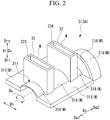
- the upper half body 311 is arranged on the upper side in the vertical direction Dv with the axis O as a reference. As illustrated in FIG. 2 , the upper half body 311 is formed in a semi-tubular shape so as to have a semicircular cross section which is open downward when viewed from the axial direction Da.
- An upper flange (flange) 313 extending in the horizontal direction Dh is formed at each of both ends of the upper half body 311 in the circumferential direction Dc.
- the upper half body 311 is formed by welding the upper flanges 313 and a plurality of upper body block portions (body block portions) 318 in the axial direction Da.
- the lower half body 312 is arranged on the lower side in the vertical direction Dv with the axis O as a reference. As illustrated in FIG. 3 , the lower half body 312 is formed in a semi-tubular shape so as to have a circular cross section which is open upward when viewed from the axial direction Da. A lower flange (flange) 314 extending in the horizontal direction Dh is formed at each of both ends of the lower half body 312 in the circumferential direction Dc. In the embodiment, the lower half body 312 is formed by welding the lower flanges 314 and a plurality of lower body block portions (body block portions) 319 in the axial direction Da.
- the upper half body 311 and the lower half body 312 constitute the casing body 31 by being connected to each other using connection means such as a bolt in a state where the upper flanges 313 and the lower flanges 314 abut each other in the vertical direction Dv.
- the inlet valve chamber 32 is arranged to be connected to the steam inlet 35 of the casing body 31.
- the inlet valve chamber 32 can control the pressure and flow rate of the steam that flows into the casing body 31 from the steam inlet 35.
- a pressure control valve and a main stop valve are arranged in the inlet valve chamber 32.
- the pressure control valve and the main stop valve may be integrated.
- the inlet valve chamber 32 is a tubular member that is arranged to protrude to the outer side Dro in the radial direction Dr from the casing body 31.
- the inlet valve chamber 32 is formed in a rectangular tubular shape extending upward in the vertical direction Dv from the casing body 31.
- the inlet valve chamber 32 extends upward in the vertical direction Dv from an upper portion of the upper half body 311 in the vertical direction Dv.
- An inlet flow path portion (flow path portion) 323 that communicates with the inside of the casing body 31 is formed in the inlet valve chamber 32.
- the extraction pressure control valve chamber 33 is arranged to be connected to the inside of the casing body 31, at an intermediate portion of the casing body 31 in the axial direction Da.
- the extraction pressure control valve chamber 33 controls the pressure of the steam which is extracted from the outside and flows into the inside of the casing body 31.
- the extraction pressure control valve chamber 33 is a tubular member that is arranged to protrude to the outer side Dro in the radial direction Dr from the casing body 31.
- the extraction pressure control valve chamber 33 is formed in a rectangular tubular shape extending upward in the vertical direction Dv from the upper portion of the upper half body 311.
- An extraction pressure control flow path portion (flow path portion) 334 that communicates with the inside of the casing body 31 is formed in the extraction pressure control valve chamber 33.
- the casing 3 has an inner nozzle 333 that sends the extracted steam to the stator vanes 317 inside the casing body 31.
- the inner nozzle 333 is arranged in the extraction pressure control flow path portion 334.
- the inner nozzle 333 is provided separately from the extraction pressure control valve chamber 33.
- the inner nozzle 333 is connected to supply the steam to the stator vanes 317 which are positioned on the second side Da2 of the extraction pressure control valve chamber 33 in the axial direction Da.
- the extraction port 34 is arranged to be connected to the inside of the casing body 31, at the intermediate portion of the casing body 31 in the axial direction Da. Through the extraction port 34, the steam in the casing body 31 is extracted to the outside.
- the extraction port 34 is a tubular member that is arranged to protrude to the outer side Dro in the radial direction Dr from the casing body 31.
- the extraction port 34 is formed in a tubular shape extending downward in the vertical direction Dv from the lower portion of the lower half body 312.
- the extraction port 34 of the embodiment is formed such that the position thereof in the axial direction Da overlaps the position of the extraction pressure control valve chamber 33.
- An extraction flow path portion (flow path portion) 343 that communicates with the inside of the casing body 31 is formed in the extraction port 34.
- the upper half body 311, the inlet valve chamber 32, the extraction pressure control valve chamber 33 as described above are integrated by being welded to each other at the manufacturing stage, to form the upper half casing 3A. Further, the lower half body 312 and the extraction port 34 are integrated by being welded to each other at the manufacturing stage, to form the lower half casing 3B.
- a manufacturing method S 1 of the casing 3 has a step S2 of forming a plurality of metal members M, a step S3 of arranging the plurality of metal members M, and a step S4 of forming the casing 3.
- step S2 of forming the plurality of metal members M the plurality of metal members M as components constituting the casing 3 are formed.
- the plurality of metal members M are the plurality upper body block portions 318 and the upper flanges 313 which constitute the upper half body 311, the plurality of lower body block portions 319 and the lower flanges 314 which constitute the lower half body 312, the inlet valve chamber 32, the extraction pressure control valve chamber 33, and the extraction port 34.
- these metal members M are manufactured by at least two kinds of manufacturing methods among forging, steel plate processing, casting, and a fused metal deposition method. That is, not all metal members M are manufactured by one kind of manufacturing method such as casting, and in step S2 of forming the metal members M, at least one metal member M is manufactured by the fused metal deposition method.
- the upper body block portion 318 and the lower body block portion 319 are formed by forging or steel plate processing.
- the upper body block portion 318 and the lower body block portion 319 which have a semicircular cross section are formed by vertically dividing a material, which is formed in an annular shape by forging, into two parts.
- the upper body block portion 318 and the lower body block portion 319 are formed by bending a flat steel plate into a semicircular cross section by bending processing using a roller or the like, or by punching a member having a semicircular cross section by pressing processing.
- the upper flange 313 and the lower flange 314 are formed by forging or steel plate processing.
- the upper flange 313 and the lower flange 314 which have a predetermined shape are formed by performing cutting using cutting means such as gas cutting or mechanical cutting processing on a metal material larger than the upper flange 313 and the lower flange 314.
- a block-shaped metal material which is smaller than the upper flange 313 and the lower flange 314 and has a simple shape such as a square, is first manufactured by forging. Then, the upper flange 313 and the lower flange 314 having a predetermined shape are formed by welding the small block-shaped metal materials.
- the inlet valve chamber 32 is formed as the thickest member in the casing 3 by the fused metal deposition method or casting so as to withstand the high-pressure steam.
- the fused metal deposition method for example, the inlet valve chamber 32 having a predetermined shape is formed by depositing fused metal on a steel plate or forged material as a base.
- the members separately formed by the fused metal deposition method may be integrally formed by welding.
- the extraction pressure control valve chamber 33 is formed by the fused metal deposition method or steel plate processing.
- the extraction pressure control valve chamber 33 having a predetermined shape is formed by depositing fused metal on a steel plate or forged material as a base. Further, in the forming by the steel plate processing, the extraction pressure control valve chamber 33 having a predetermined shape is formed by welding a plate member formed by the steel plate or forging.
- the inner nozzle 333 which is separately manufactured, is arranged inside the extraction pressure control valve chamber 33.
- the inner nozzle 333 can be formed by the steel plate processing, forging or fused metal deposition method.
- the extraction port 34 is formed by the fused metal deposition method or steel plate processing.
- the extraction port 34 having a predetermined shape is formed by depositing fused metal on a steel plate or forged material as a base. Further, in the forming by the steel plate processing, the extraction port 34 having a predetermined shape is formed by welding a plate member formed by the steel plate or forging.
- step S3 of arranging the plurality of metal members M the plurality of metal members M are arranged according to a shape of the casing 3 to be formed. That is, the plurality of upper body block portions 318 and the upper flanges 313 which constitute the upper half body 311 of the casing 3, the inlet valve chamber 32, the extraction pressure control valve chamber 33 are arranged to abut each other. Further, the plurality of lower body block portions 319 and the lower flanges 314 which constitute the lower half body 312, and the extraction port 34 are arranged to abut each other.
- step S4 of forming the casing 3 the casing 3 is formed by welding the plurality of metal members M to each other. That is, the upper body block portions 318, the upper flanges 313, the inlet valve chamber 32, and the extraction pressure control valve chamber 33 which abut each other are integrally joined by welding. Further, the plurality of lower body block portions 319 and the lower flanges 314 which constitute the lower half body 312, and the extraction port 34, which abut each other, are integrally joined by welding.
- step S3 of arranging the plurality of metal members M and step S4 of forming the casing 3 arranging two metal members M, which are adjacent to each other, so as to abut each other and then welding both the metal members M may be repeatedly performed in sequence.
- the inlet valve chamber 32, the extraction pressure control valve chamber 33, and the extraction port 34 which are tubular members are joined as follows.
- the upper half body 311 and the lower half body 312 which constitute the casing body 31 has a communication opening 71 at a portion where each of the inlet valve chamber 32, the extraction pressure control valve chamber 33, and the extraction port 34 is joined.
- the communication opening 71 penetrates the casing body 31 in the radial direction Dr, and is open on the outer circumferential surface so as to communicate with the inside of the casing body 31.
- the communication openings 71 are formed such that end portions 32s, 33s, and 34s of the inlet valve chamber 32, the extraction pressure control valve chamber 33, and the extraction port 34 on the inner side Dri in the radial direction Dr can be inserted.
- the communication openings 71 in the embodiment are the steam inlet 35, the steam outlet 36, the steam intermediate inlet 37, and the steam intermediate outlet 38.
- the end portions 32s, 33s, and 34s of the inlet valve chamber 32, the extraction pressure control valve chamber 33, and the extraction port 34 on the inner side Dri in the radial direction Dr are inserted into the communication openings 71, and the edge portion of the communication opening 71 and each of the inlet valve chamber 32, the extraction pressure control valve chamber 33, and the extraction port 34 are welded to form a welded portion 50.
- step S3 of arranging the plurality of metal members M the plurality of upper body block portions 318 and the upper flanges 313 are arranged to form the communication openings 71.
- the inlet valve chamber 32 and the extraction pressure control valve chamber 33 are arranged in a state where the end portion 32s of the inlet valve chamber 32 and the end portion 33s of the extraction pressure control valve chamber 33 are inserted into the communication openings 71.
- the plurality of lower body block portions 319 and the lower flanges 314 are arranged to form the communication opening 71.
- the extraction port 34 is arranged in a state where the end portion 34s of the extraction port 34 is inserted into the communication opening 71.
- step S4 of forming the casing 3 the inlet valve chamber 32, the extraction pressure control valve chamber 33, and the extraction port 34 are welded to the casing body 31.
- the plurality of metal members M for constituting the casing 3 are manufactured by at least two kinds of manufacturing methods among the forging, steel plate processing, casting, and fused metal deposition method. Therefore, it is not necessary to manufacture the entire casing 3 by casting, thereby making it is possible to reduce the labor and cost of manufacturing the mold. Accordingly, the period of time required for manufacturing the metal members M is very short as compared with a case where the entire casing 3 is manufactured as one component by casting. As a result, the period of time required for manufacturing the casing 3 can be shortened. Further, it is also possible to use different metal materials depending on the parts of the casing 3. As a result, it is possible to reduce the cost of manufacturing the casing 3.
- step S2 of forming the metal members M at least one metal member M is manufactured by the fused metal deposition method. Thereby, even a metal member M having a complicated shape can be efficiently manufactured without using the mold.
- the upper half body 311 and the lower half body 312 are manufactured by being divided into the plurality of upper body block portions 318 and the plurality of lower body block portions 319.
- each of the upper body block portions 318 and the lower body block portions 319 is downsized, and thereby is easily manufactured and handled.
- the upper flanges 313 and the lower flanges 314 are formed by steel plate processing or forging. Thereby, the upper flanges 313 and the lower flanges 314 for connecting the upper half body 311 and the lower half body 312 can be easily formed as separate members with a structure or material having a higher strength than the upper body block portions 318 and the lower body block portions 319.
- step S2 of forming the metal members M the inlet valve chamber 32, the extraction pressure control valve chamber 33, and the extraction port 34 which are tubular members are formed by any one of the fused metal deposition method, casting, and steel plate processing.
- the inlet valve chamber 32, the extraction pressure control valve chamber 33, and the extraction port 34 which may have a complicated shape as compared with the casing body 31 can be efficiently manufactured by the fused metal deposition method.
- the inlet valve chamber 32 in which the temperature and pressure of the steam (fluid) flowing the inlet flow path portion 323 is high is manufactured by the fused metal deposition method or casting, so that the inlet valve chamber 32 can be manufactured to have high strength that can withstand the high temperature and pressure.
- the end portion 32s of the inlet valve chamber 32, the end portion 33s of the extraction pressure control valve chamber 33, and the end portion 34s of the extraction port 34 are inserted into the communication openings 71 formed in the casing 3 and are welded, so that the inlet flow path portion 323, the extraction pressure control flow path portion 334, and the extraction flow path portion 343 communicate with the inside of the casing body 31 as they are.
- the inlet valve chamber 32, the extraction pressure control valve chamber 33, and the extraction port 34 can be easily connected to the casing body 31. Further, there is no need to perform welding inside the casing body 31, the inside of the inlet valve chamber 32, the extraction pressure control valve chamber 33, or the extraction port 34.
- the inlet valve chamber 32, the extraction pressure control valve chamber 33, and the extraction port 34 are fixed to the casing body 31 by being welded in a state where the end portions thereof on the inner side Dri in the radial direction Dr are inserted into the communication openings 71, but the fixing method is not limited thereto.
- communication openings 71A may be formed in a size such that the end portion 32s of the inlet valve chamber 32, the end portion 33s of the extraction pressure control valve chamber 33, the end portion 34s of the extraction port 34 cannot be inserted.
- a casing 3 is formed by welding in a state where the end portion 32s of the inlet valve chamber 32, the end portion 33s of the extraction pressure control valve chamber 33, and the end portion 34s of the extraction port 34 are in contact with an outer circumferential surface 31f of the casing body 31.
- step S3 of arranging the plurality of metal members M the plurality of upper body block portions 318 and the upper flanges 313 are arranged to form the communication openings 71A. Then, the end surface of the end portion 32s of the inlet valve chamber 32, the end surface of the end portion 33s of the extraction pressure control valve chamber 33 are arranged in a state of being in contact with the outer circumferential surface 31f forming the edge portion of the communication opening 71A. Accordingly, the steam inlet 35 which is the communication opening 71A communicates with the inlet flow path portion 323. Further, the steam intermediate inlet 37 which is the communication opening 71A communicates with the extraction pressure control flow path portion 334.
- the plurality of lower body block portions 319 and the lower flanges 314 are arranged to form the communication opening 71A. Then, the end surface of the end portion 34s of the extraction port 34 is arranged in a state of being in contact with the outer circumferential surface 31f forming the edge portion of the communication opening 71A. Accordingly, the steam intermediate outlet 38 which is the communication opening 71A communicates with the extraction flow path portion 343.
- step S4 of forming the casing 3 the end portion 32s of the inlet valve chamber 32, the end portion 33s of the extraction pressure control valve chamber 33, and the end portion 34s of the extraction port 34 are welded to the outer circumferential surface 31f of the casing body 31.
- the inlet valve chamber 32, the extraction pressure control valve chamber 33, and the extraction port 34 are arranged only in a region on the outer side Dro of the outer circumferential surface 31f of the casing body 31 in the radial direction Dr. That is, as compared with the structure in which the inlet valve chamber 32, the extraction pressure control valve chamber 33, and the extraction port 34 are inserted into the communication opening 71 as in the embodiment, the volumes of the inlet valve chamber 32, the extraction pressure control valve chamber 33, and the extraction port 34 are reduced. As a result, the time for manufacturing the inlet valve chamber 32, the extraction pressure control valve chamber 33, and the extraction port 34 is shortened, and thus the metal members M can be efficiently manufactured.
- the casing body 31 in another modification example may be formed by welding in a state where the end portion 32s of the inlet valve chamber 32, the end portion 33s of the extraction pressure control valve chamber 33, and the end portion 34s of the extraction port 34 are in contact with portions protruding from the outer circumferential surfaces 31f of the upper half body 311 and the lower half body 312.
- casing-side tubular members 91 that protrude to the outer side Dro in the radial direction Dr are formed in the outer circumferential surfaces 31f of the upper half body 311 and the lower half body 312.
- a casing-side flow path portion 92 that communicates with the inside of the casing body 31 is formed in the casing-side tubular member 91.
- step S3 of arranging the plurality of metal members M the end surface of the end portion 32s of the inlet valve chamber 32, and the end surface of the end portion 33s of the extraction pressure control valve chamber 33 are arranged in a state of being in contact with the end surfaces of distal end portions on the outer side Dro of the casing-side tubular members 91 in the radial direction Dr. Accordingly, the casing-side flow path portions 92 communicate with the inlet flow path portion 323 and the extraction pressure control flow path portion 334.
- the end surface of the end portion 34s of the extraction port 34 is arranged in a state of being in contact with the end surface of a distal end portion on the outer side Dro of the casing-side tubular member 91 in the radial direction Dr. Accordingly, the casing-side flow path portion 92 communicates with the extraction flow path portion 343.
- step S4 of forming the casing 3 the end portion 32s of the inlet valve chamber 32, the end portion 33s of the extraction pressure control valve chamber 33, and the end portion 34s of the extraction port 34 are welded to the distal end portions of the casing-side tubular members 91.
- the inlet valve chamber 32, the extraction pressure control valve chamber 33, and the extraction port 34 are arranged only in a region further on the outer side Dro of the casing-side tubular member 91 that is positioned on the outer side Dro of the outer circumferential surface 31f of the casing body 31 in the radial direction Dr. That is, as compared with the structure in which the inlet valve chamber 32, the extraction pressure control valve chamber 33, and the extraction port 34 are inserted into the communication opening 71 as in the embodiment, the volumes of the inlet valve chamber 32, the extraction pressure control valve chamber 33, and the extraction port 34 are considerably reduced.
- the time for manufacturing the inlet valve chamber 32, the extraction pressure control valve chamber 33, and the extraction port 34 is significantly shortened, and thus the metal members M can be efficiently manufactured.
- the joint surfaces between the casing-side tubular members 91 and the inlet valve chamber 32, the extraction pressure control valve chamber 33, and the extraction port 34 can be made flat, and thus the joint surfaces can be easily formed.
- the steam turbine 1 has a structure including the extraction pressure control valve chamber 33 and the extraction port 34, but these configurations are not essential and can be omitted.
- the plurality of upper body block portions 318 constituting the upper half body 311 and the plurality of lower body block portions 319 constituting the lower half body 312 are manufactured by forging or steel plate processing, but the present disclosure is not limited thereto.
- Each of the upper half body 311 and the lower half body 312 may be integrally molded by casting instead of the divided structure such as the upper body block portions 318 and the lower body block portions 319.
- the inner nozzle 333 and the extraction pressure control valve chamber 33 are not limited to being separate bodies.
- the inner nozzle 333 may be formed as one component integrated with the extraction pressure control valve chamber 33 by the fused metal deposition method.
- the casing 3 is not limited to the one applied to the steam turbine 1, and may be applied to other rotating machines such as a gas turbine and a compressor.
- the manufacturing method S 1 of the casing 3 described in the embodiment is grasped as follows, for example.
- tubular members 32, 33, and 34 are arranged only in a region further on the outer side Dro of the casing-side tubular member 91 that is positioned on the outer side Dro of the outer circumferential surface 31f of the casing body 31 in the radial direction Dr. That is, the volumes of the tubular members 32, 33, and 34 are considerably reduced. As a result, the time for manufacturing the tubular members 32, 33, and 34 is significantly shortened, and thus the metal members M can be efficiently manufactured.
Landscapes
- Engineering & Computer Science (AREA)
- Mechanical Engineering (AREA)
- Chemical & Material Sciences (AREA)
- Manufacturing & Machinery (AREA)
- Materials Engineering (AREA)
- Composite Materials (AREA)
- General Engineering & Computer Science (AREA)
- Valve Housings (AREA)
- Butt Welding And Welding Of Specific Article (AREA)
Abstract
Description
- The present disclosure relates to a manufacturing method of a casing.
- In a rotating machine such as a steam turbine, a gas turbine, and a centrifugal compressor, a casing in which a rotor is housed has generally a structure formed by casting. The casing can be vertically divided into an upper half casing and a lower half casing. Each of the upper half casing and the lower half casing is integrally formed by casting. However, it is necessary to prepare a mold in a case of forming a casing by casting. It takes a lot of time to make a large mold for forming a large metal member such as a casing.
- Japanese Unexamined Patent Application, First Publication No.
S58-133405 - However, even in the configuration disclosed in Japanese Unexamined Patent Application, First Publication No.
S58-133405 - The present disclosure provides a manufacturing method of a casing which can shorten a period of time for the manufacturing.
- A manufacturing method of a casing according to an aspect of the present disclosure includes a step of manufacturing a plurality of metal members which constitute the casing including a casing body having a tubular shape that extends around an axis; a step of arranging the plurality of metal members according to a shape of the casing to be formed; and a step of forming the casing by welding the plurality of metal members to each other, in which in the step of manufacturing the metal members, the plurality of metal members are manufactured by at least two kinds of manufacturing methods among forging, steel plate processing, casting, and a fused metal deposition method.
- According to the manufacturing method of the casing of the present disclosure, it is possible to shorten the period of time for manufacturing a casing.
-
-
FIG. 1 is a diagram illustrating a schematic configuration of a steam turbine including a casing manufactured by using a manufacturing method of a casing according to an embodiment. -
FIG. 2 is a perspective view illustrating an upper half part of the casing. -
FIG. 3 is a perspective view of a lower half part of the casing viewed upside down in a vertical direction. -
FIG. 4 is a flowchart illustrating a procedure of the manufacturing method of the casing according to the embodiment. -
FIG. 5 is a perspective development view illustrating a plurality of metal components constituting the upper half part of the casing. -
FIG. 6 is a sectional view illustrating an example of a joint structure of a tubular member and a casing body. -
FIG. 7 is a sectional view illustrating another example of the joint structure of the tubular member and the casing body. -
FIG. 8 is a perspective view illustrating still another example of the joint structure of the tubular member and the casing body. -
FIG. 9 is a sectional view illustrating still another example of the joint structure of the tubular member and the casing body. - Hereinafter, a mode for implementing a manufacturing method of a casing according to the present disclosure will be described with reference to the accompanying drawings. However, the present disclosure is not limited to the embodiment only.
- In the embodiment, a
casing 3 is applied to asteam turbine 1. As illustrated inFIG. 1 , thesteam turbine 1 includes arotor 2, and thecasing 3. - The
rotor 2 includes a rotatingshaft 21 androtor blades 22. The rotatingshaft 21 is formed in a columnar shape extending in an axial direction Da with an axis O as the center. Both end portions of the rotatingshaft 21 are supported by a first bearing 23A and a second bearing 23B so as to be rotatable around the axis O. The first bearing 23A and the second bearing 23B are fixed to thecasing 3. Therotor blades 22 are arranged to constitute a plurality of stages at intervals in the axial direction Da. Each of therotor blades 22 is fixed to the outer circumferential surface of the rotatingshaft 21 so as to extend to an outer side Dro in a radial direction Dr. - In the following, a direction in which the axis O extends is referred to as the axial direction Da. The radial direction with respect to the axis O is simply referred to as the radial direction Dr. An up-down direction of the paper of
FIG. 1 , which is a part of the radial direction Dr is referred to as a vertical direction Dv. A direction which is part of the radial direction Dr and is orthogonal to the vertical direction Dv is referred to as a horizontal direction Dh (refer toFIG. 2 ) that is a width direction of thesteam turbine 1. A direction around therotor 2 with the axis O as the center is referred to as a circumferential direction Dc. Further, a first side Da1 of the axial direction Da is an upstream side in a flow direction of steam flowing inside thecasing 3. A second side Da2 of the axial direction Da is a downstream side in the flow direction of the steam flowing inside thecasing 3. - The
casing 3 is arranged to cover therotor 2. Thecasing 3 can be divided into anupper half casing 3A and alower half casing 3B with a horizontal plane including the axis O as a reference. As illustrated inFIG. 1 ,upper half diaphragms 315A having a semicircular shape viewed from the axial direction Da are fixed on an inner side Dri of theupper half casing 3A in the radial direction Dr.Lower half diaphragms 315B having a semicircular shape viewed from the axial direction Da are fixed on the inner side Dri of thelower half casing 3B in the radial direction Dr. Theupper half diaphragms 315A and thelower half diaphragms 315B are arranged on the first side Da1 of therotor blades 22 of each stage in the axial direction Da. In theupper half diaphragm 315A and thelower half diaphragm 315B, a plurality ofstator vanes 317 which are lined up in the circumferential direction Dc are arranged at a position on the first side Da1 of therotor blades 22 in the axial direction Da. Thecasing 3 of the embodiment includes acasing body 31, aninlet valve chamber 32, an extraction pressurecontrol valve chamber 33, and anextraction port 34. - The
casing body 31 is formed in a tubular shape extending in the axial direction Da. Thecasing body 31 covers therotor 2 from the outer side in the radial direction Dr. In thecasing body 31, asteam inlet 35, asteam outlet 36, a steamintermediate inlet 37, a steamintermediate outlet 38 are formed. - The
steam inlet 35 is formed on the first side Da1 of the center of thecasing body 31 in the axial direction Da. Thesteam inlet 35 is a through-hole communicating with the inside and outside of thecasing body 31. The steamintermediate inlet 37 is formed between thesteam inlet 35 and thesteam outlet 36 in the axial direction Da. The steamintermediate inlet 37 is a through-hole communicating with the inside and outside of thecasing body 31. Through thesteam inlet 35 and the steamintermediate inlet 37, steam (fluid) from the outside of thecasing body 31 is introduced into the inside of thecasing body 31. - The
steam outlet 36 is arranged on the second side Da2 of the center of thecasing body 31 in the axial direction Da. Thesteam outlet 36 is a through-hole communicating with the inside and outside of thecasing body 31. The steamintermediate outlet 38 is formed between thesteam inlet 35 and thesteam outlet 36 in the axial direction Da. The steamintermediate outlet 38 is formed at a position that is substantially the same as the steamintermediate inlet 37 in the axial direction Da and is on a side opposite to the steamintermediate inlet 37 in the circumferential direction Dc. The steamintermediate outlet 38 is a through-hole communicating with the inside and outside of thecasing body 31. Through thesteam outlet 36 and the steamintermediate outlet 38, the steam that has flowed inside thecasing body 31 is discharged to the outside. - The
casing body 31 includes an upperhalf body 311, and alower half body 312. The upperhalf body 311 is arranged on the upper side in the vertical direction Dv with the axis O as a reference. As illustrated inFIG. 2 , the upperhalf body 311 is formed in a semi-tubular shape so as to have a semicircular cross section which is open downward when viewed from the axial direction Da. An upper flange (flange) 313 extending in the horizontal direction Dh is formed at each of both ends of the upperhalf body 311 in the circumferential direction Dc. In the embodiment, the upperhalf body 311 is formed by welding theupper flanges 313 and a plurality of upper body block portions (body block portions) 318 in the axial direction Da. - As illustrated in
FIG. 1 , thelower half body 312 is arranged on the lower side in the vertical direction Dv with the axis O as a reference. As illustrated inFIG. 3 , thelower half body 312 is formed in a semi-tubular shape so as to have a circular cross section which is open upward when viewed from the axial direction Da. A lower flange (flange) 314 extending in the horizontal direction Dh is formed at each of both ends of thelower half body 312 in the circumferential direction Dc. In the embodiment, thelower half body 312 is formed by welding thelower flanges 314 and a plurality of lower body block portions (body block portions) 319 in the axial direction Da. - The upper
half body 311 and thelower half body 312 constitute thecasing body 31 by being connected to each other using connection means such as a bolt in a state where theupper flanges 313 and thelower flanges 314 abut each other in the vertical direction Dv. - The
inlet valve chamber 32 is arranged to be connected to thesteam inlet 35 of thecasing body 31. Theinlet valve chamber 32 can control the pressure and flow rate of the steam that flows into thecasing body 31 from thesteam inlet 35. Specifically, a pressure control valve and a main stop valve are arranged in theinlet valve chamber 32. In theinlet valve chamber 32, the pressure control valve and the main stop valve may be integrated. Theinlet valve chamber 32 is a tubular member that is arranged to protrude to the outer side Dro in the radial direction Dr from thecasing body 31. Theinlet valve chamber 32 is formed in a rectangular tubular shape extending upward in the vertical direction Dv from thecasing body 31. Theinlet valve chamber 32 extends upward in the vertical direction Dv from an upper portion of the upperhalf body 311 in the vertical direction Dv. An inlet flow path portion (flow path portion) 323 that communicates with the inside of thecasing body 31 is formed in theinlet valve chamber 32. - The extraction pressure
control valve chamber 33 is arranged to be connected to the inside of thecasing body 31, at an intermediate portion of thecasing body 31 in the axial direction Da. The extraction pressurecontrol valve chamber 33 controls the pressure of the steam which is extracted from the outside and flows into the inside of thecasing body 31. The extraction pressurecontrol valve chamber 33 is a tubular member that is arranged to protrude to the outer side Dro in the radial direction Dr from thecasing body 31. The extraction pressurecontrol valve chamber 33 is formed in a rectangular tubular shape extending upward in the vertical direction Dv from the upper portion of the upperhalf body 311. An extraction pressure control flow path portion (flow path portion) 334 that communicates with the inside of thecasing body 31 is formed in the extraction pressurecontrol valve chamber 33. - In addition, the
casing 3 has aninner nozzle 333 that sends the extracted steam to thestator vanes 317 inside thecasing body 31. Theinner nozzle 333 is arranged in the extraction pressure controlflow path portion 334. Theinner nozzle 333 is provided separately from the extraction pressurecontrol valve chamber 33. Theinner nozzle 333 is connected to supply the steam to thestator vanes 317 which are positioned on the second side Da2 of the extraction pressurecontrol valve chamber 33 in the axial direction Da. - The
extraction port 34 is arranged to be connected to the inside of thecasing body 31, at the intermediate portion of thecasing body 31 in the axial direction Da. Through theextraction port 34, the steam in thecasing body 31 is extracted to the outside. Theextraction port 34 is a tubular member that is arranged to protrude to the outer side Dro in the radial direction Dr from thecasing body 31. Theextraction port 34 is formed in a tubular shape extending downward in the vertical direction Dv from the lower portion of thelower half body 312. Theextraction port 34 of the embodiment is formed such that the position thereof in the axial direction Da overlaps the position of the extraction pressurecontrol valve chamber 33. An extraction flow path portion (flow path portion) 343 that communicates with the inside of thecasing body 31 is formed in theextraction port 34. - The upper
half body 311, theinlet valve chamber 32, the extraction pressurecontrol valve chamber 33 as described above are integrated by being welded to each other at the manufacturing stage, to form theupper half casing 3A. Further, thelower half body 312 and theextraction port 34 are integrated by being welded to each other at the manufacturing stage, to form thelower half casing 3B. - As illustrated in
FIG. 4 , amanufacturing method S 1 of thecasing 3 has a step S2 of forming a plurality of metal members M, a step S3 of arranging the plurality of metal members M, and a step S4 of forming thecasing 3. - In step S2 of forming the plurality of metal members M, the plurality of metal members M as components constituting the
casing 3 are formed. In the embodiment, as illustrated inFIGS. 2 ,3 , and5 , the plurality of metal members M are the plurality upperbody block portions 318 and theupper flanges 313 which constitute the upperhalf body 311, the plurality of lowerbody block portions 319 and thelower flanges 314 which constitute thelower half body 312, theinlet valve chamber 32, the extraction pressurecontrol valve chamber 33, and theextraction port 34. In step S2 of forming the metal members M, these metal members M are manufactured by at least two kinds of manufacturing methods among forging, steel plate processing, casting, and a fused metal deposition method. That is, not all metal members M are manufactured by one kind of manufacturing method such as casting, and in step S2 of forming the metal members M, at least one metal member M is manufactured by the fused metal deposition method. - In the embodiment, the upper
body block portion 318 and the lowerbody block portion 319 are formed by forging or steel plate processing. In the forming by forging, for example, the upperbody block portion 318 and the lowerbody block portion 319 which have a semicircular cross section are formed by vertically dividing a material, which is formed in an annular shape by forging, into two parts. In the forming by steel plate processing, for example, the upperbody block portion 318 and the lowerbody block portion 319 are formed by bending a flat steel plate into a semicircular cross section by bending processing using a roller or the like, or by punching a member having a semicircular cross section by pressing processing. - In addition, the
upper flange 313 and thelower flange 314 are formed by forging or steel plate processing. In the forming by forging or steel plate processing, theupper flange 313 and thelower flange 314 which have a predetermined shape are formed by performing cutting using cutting means such as gas cutting or mechanical cutting processing on a metal material larger than theupper flange 313 and thelower flange 314. As another forming method by forging, a block-shaped metal material, which is smaller than theupper flange 313 and thelower flange 314 and has a simple shape such as a square, is first manufactured by forging. Then, theupper flange 313 and thelower flange 314 having a predetermined shape are formed by welding the small block-shaped metal materials. - In the
steam turbine 1, the steam having the highest pressure flows through theinlet valve chamber 32. Therefore, theinlet valve chamber 32 is formed as the thickest member in thecasing 3 by the fused metal deposition method or casting so as to withstand the high-pressure steam. In the forming by the fused metal deposition method, for example, theinlet valve chamber 32 having a predetermined shape is formed by depositing fused metal on a steel plate or forged material as a base. In addition, depending on the shape of theinlet valve chamber 32, the members separately formed by the fused metal deposition method may be integrally formed by welding. - The extraction pressure
control valve chamber 33 is formed by the fused metal deposition method or steel plate processing. In the forming by the fused metal deposition method, for example, the extraction pressurecontrol valve chamber 33 having a predetermined shape is formed by depositing fused metal on a steel plate or forged material as a base. Further, in the forming by the steel plate processing, the extraction pressurecontrol valve chamber 33 having a predetermined shape is formed by welding a plate member formed by the steel plate or forging. Theinner nozzle 333, which is separately manufactured, is arranged inside the extraction pressurecontrol valve chamber 33. Theinner nozzle 333 can be formed by the steel plate processing, forging or fused metal deposition method. - The
extraction port 34 is formed by the fused metal deposition method or steel plate processing. In the forming by the fused metal deposition method, for example, theextraction port 34 having a predetermined shape is formed by depositing fused metal on a steel plate or forged material as a base. Further, in the forming by the steel plate processing, theextraction port 34 having a predetermined shape is formed by welding a plate member formed by the steel plate or forging. - In step S3 of arranging the plurality of metal members M, the plurality of metal members M are arranged according to a shape of the
casing 3 to be formed. That is, the plurality of upperbody block portions 318 and theupper flanges 313 which constitute the upperhalf body 311 of thecasing 3, theinlet valve chamber 32, the extraction pressurecontrol valve chamber 33 are arranged to abut each other. Further, the plurality of lowerbody block portions 319 and thelower flanges 314 which constitute thelower half body 312, and theextraction port 34 are arranged to abut each other. - In step S4 of forming the
casing 3, thecasing 3 is formed by welding the plurality of metal members M to each other. That is, the upperbody block portions 318, theupper flanges 313, theinlet valve chamber 32, and the extraction pressurecontrol valve chamber 33 which abut each other are integrally joined by welding. Further, the plurality of lowerbody block portions 319 and thelower flanges 314 which constitute thelower half body 312, and theextraction port 34, which abut each other, are integrally joined by welding. - In step S3 of arranging the plurality of metal members M and step S4 of forming the
casing 3, arranging two metal members M, which are adjacent to each other, so as to abut each other and then welding both the metal members M may be repeatedly performed in sequence. - In the embodiment, the
inlet valve chamber 32, the extraction pressurecontrol valve chamber 33, and theextraction port 34 which are tubular members are joined as follows. - As illustrated in
FIG. 6 , the upperhalf body 311 and thelower half body 312 which constitute thecasing body 31 has a communication opening 71 at a portion where each of theinlet valve chamber 32, the extraction pressurecontrol valve chamber 33, and theextraction port 34 is joined. The communication opening 71 penetrates thecasing body 31 in the radial direction Dr, and is open on the outer circumferential surface so as to communicate with the inside of thecasing body 31. The communication openings 71 are formed such thatend portions inlet valve chamber 32, the extraction pressurecontrol valve chamber 33, and theextraction port 34 on the inner side Dri in the radial direction Dr can be inserted. The communication openings 71 in the embodiment are thesteam inlet 35, thesteam outlet 36, the steamintermediate inlet 37, and the steamintermediate outlet 38. Theend portions inlet valve chamber 32, the extraction pressurecontrol valve chamber 33, and theextraction port 34 on the inner side Dri in the radial direction Dr are inserted into the communication openings 71, and the edge portion of the communication opening 71 and each of theinlet valve chamber 32, the extraction pressurecontrol valve chamber 33, and theextraction port 34 are welded to form a weldedportion 50. - More specifically, in step S3 of arranging the plurality of metal members M, the plurality of upper
body block portions 318 and theupper flanges 313 are arranged to form the communication openings 71. Then, theinlet valve chamber 32 and the extraction pressurecontrol valve chamber 33 are arranged in a state where theend portion 32s of theinlet valve chamber 32 and theend portion 33s of the extraction pressurecontrol valve chamber 33 are inserted into the communication openings 71. Similarly, the plurality of lowerbody block portions 319 and thelower flanges 314 are arranged to form the communication opening 71. Then, theextraction port 34 is arranged in a state where theend portion 34s of theextraction port 34 is inserted into the communication opening 71. In a state where each of the components is arranged in this manner, in step S4 of forming thecasing 3, theinlet valve chamber 32, the extraction pressurecontrol valve chamber 33, and theextraction port 34 are welded to thecasing body 31. - According to the manufacturing method S1 of the
casing 3 as described above, the plurality of metal members M for constituting thecasing 3 are manufactured by at least two kinds of manufacturing methods among the forging, steel plate processing, casting, and fused metal deposition method. Therefore, it is not necessary to manufacture theentire casing 3 by casting, thereby making it is possible to reduce the labor and cost of manufacturing the mold. Accordingly, the period of time required for manufacturing the metal members M is very short as compared with a case where theentire casing 3 is manufactured as one component by casting. As a result, the period of time required for manufacturing thecasing 3 can be shortened. Further, it is also possible to use different metal materials depending on the parts of thecasing 3. As a result, it is possible to reduce the cost of manufacturing thecasing 3. - In addition, in step S2 of forming the metal members M, at least one metal member M is manufactured by the fused metal deposition method. Thereby, even a metal member M having a complicated shape can be efficiently manufactured without using the mold.
- Further, the upper
half body 311 and thelower half body 312 are manufactured by being divided into the plurality of upperbody block portions 318 and the plurality of lowerbody block portions 319. As a result, each of the upperbody block portions 318 and the lowerbody block portions 319 is downsized, and thereby is easily manufactured and handled. Further, it is also possible to use different metal materials depending on the parts of thecasing body 31. - The
upper flanges 313 and thelower flanges 314 are formed by steel plate processing or forging. Thereby, theupper flanges 313 and thelower flanges 314 for connecting the upperhalf body 311 and thelower half body 312 can be easily formed as separate members with a structure or material having a higher strength than the upperbody block portions 318 and the lowerbody block portions 319. - In step S2 of forming the metal members M, the
inlet valve chamber 32, the extraction pressurecontrol valve chamber 33, and theextraction port 34 which are tubular members are formed by any one of the fused metal deposition method, casting, and steel plate processing. Thereby, theinlet valve chamber 32, the extraction pressurecontrol valve chamber 33, and theextraction port 34 which may have a complicated shape as compared with thecasing body 31 can be efficiently manufactured by the fused metal deposition method. Further, theinlet valve chamber 32 in which the temperature and pressure of the steam (fluid) flowing the inletflow path portion 323 is high is manufactured by the fused metal deposition method or casting, so that theinlet valve chamber 32 can be manufactured to have high strength that can withstand the high temperature and pressure. - The
end portion 32s of theinlet valve chamber 32, theend portion 33s of the extraction pressurecontrol valve chamber 33, and theend portion 34s of theextraction port 34 are inserted into the communication openings 71 formed in thecasing 3 and are welded, so that the inletflow path portion 323, the extraction pressure controlflow path portion 334, and the extractionflow path portion 343 communicate with the inside of thecasing body 31 as they are. Thereby, theinlet valve chamber 32, the extraction pressurecontrol valve chamber 33, and theextraction port 34 can be easily connected to thecasing body 31. Further, there is no need to perform welding inside thecasing body 31, the inside of theinlet valve chamber 32, the extraction pressurecontrol valve chamber 33, or theextraction port 34. Therefore, since there is no welding line at the positions facing the inletflow path portion 323, the extraction pressure controlflow path portion 334, and the extractionflow path portion 343, the flow of the steam in thesteam turbine 1 is not obstructed. As a result, it is possible to suppress the efficiency reduction of thesteam turbine 1. - In the above-described embodiment, the
inlet valve chamber 32, the extraction pressurecontrol valve chamber 33, and theextraction port 34 are fixed to thecasing body 31 by being welded in a state where the end portions thereof on the inner side Dri in the radial direction Dr are inserted into the communication openings 71, but the fixing method is not limited thereto. - For example, as illustrated in
FIG. 7 , in thecasing body 31 in the modification example,communication openings 71A may be formed in a size such that theend portion 32s of theinlet valve chamber 32, theend portion 33s of the extraction pressurecontrol valve chamber 33, theend portion 34s of theextraction port 34 cannot be inserted. Such acasing 3 is formed by welding in a state where theend portion 32s of theinlet valve chamber 32, theend portion 33s of the extraction pressurecontrol valve chamber 33, and theend portion 34s of theextraction port 34 are in contact with an outercircumferential surface 31f of thecasing body 31. - Specifically, in step S3 of arranging the plurality of metal members M, the plurality of upper
body block portions 318 and theupper flanges 313 are arranged to form thecommunication openings 71A. Then, the end surface of theend portion 32s of theinlet valve chamber 32, the end surface of theend portion 33s of the extraction pressurecontrol valve chamber 33 are arranged in a state of being in contact with the outercircumferential surface 31f forming the edge portion of thecommunication opening 71A. Accordingly, thesteam inlet 35 which is thecommunication opening 71A communicates with the inletflow path portion 323. Further, the steamintermediate inlet 37 which is thecommunication opening 71A communicates with the extraction pressure controlflow path portion 334. Similarly, the plurality of lowerbody block portions 319 and thelower flanges 314 are arranged to form thecommunication opening 71A. Then, the end surface of theend portion 34s of theextraction port 34 is arranged in a state of being in contact with the outercircumferential surface 31f forming the edge portion of thecommunication opening 71A. Accordingly, the steamintermediate outlet 38 which is thecommunication opening 71A communicates with the extractionflow path portion 343. In a state where each of the components is arranged in this manner, in step S4 of forming thecasing 3, theend portion 32s of theinlet valve chamber 32, theend portion 33s of the extraction pressurecontrol valve chamber 33, and theend portion 34s of theextraction port 34 are welded to the outercircumferential surface 31f of thecasing body 31. - Thereby, the
inlet valve chamber 32, the extraction pressurecontrol valve chamber 33, and theextraction port 34 are arranged only in a region on the outer side Dro of the outercircumferential surface 31f of thecasing body 31 in the radial direction Dr. That is, as compared with the structure in which theinlet valve chamber 32, the extraction pressurecontrol valve chamber 33, and theextraction port 34 are inserted into the communication opening 71 as in the embodiment, the volumes of theinlet valve chamber 32, the extraction pressurecontrol valve chamber 33, and theextraction port 34 are reduced. As a result, the time for manufacturing theinlet valve chamber 32, the extraction pressurecontrol valve chamber 33, and theextraction port 34 is shortened, and thus the metal members M can be efficiently manufactured. - As illustrated in
FIGS. 8 and9 , thecasing body 31 in another modification example may be formed by welding in a state where theend portion 32s of theinlet valve chamber 32, theend portion 33s of the extraction pressurecontrol valve chamber 33, and theend portion 34s of theextraction port 34 are in contact with portions protruding from the outercircumferential surfaces 31f of the upperhalf body 311 and thelower half body 312. - Specifically, in the
casing body 31 of the other modification example, casing-sidetubular members 91 that protrude to the outer side Dro in the radial direction Dr are formed in the outercircumferential surfaces 31f of the upperhalf body 311 and thelower half body 312. A casing-sideflow path portion 92 that communicates with the inside of thecasing body 31 is formed in the casing-side tubular member 91. - In step S3 of arranging the plurality of metal members M, the end surface of the
end portion 32s of theinlet valve chamber 32, and the end surface of theend portion 33s of the extraction pressurecontrol valve chamber 33 are arranged in a state of being in contact with the end surfaces of distal end portions on the outer side Dro of the casing-sidetubular members 91 in the radial direction Dr. Accordingly, the casing-sideflow path portions 92 communicate with the inletflow path portion 323 and the extraction pressure controlflow path portion 334. Similarly, the end surface of theend portion 34s of theextraction port 34 is arranged in a state of being in contact with the end surface of a distal end portion on the outer side Dro of the casing-side tubular member 91 in the radial direction Dr. Accordingly, the casing-sideflow path portion 92 communicates with the extractionflow path portion 343. In a state where each of the components is arranged in this manner, in step S4 of forming thecasing 3, theend portion 32s of theinlet valve chamber 32, theend portion 33s of the extraction pressurecontrol valve chamber 33, and theend portion 34s of theextraction port 34 are welded to the distal end portions of the casing-sidetubular members 91. - Thereby, the
inlet valve chamber 32, the extraction pressurecontrol valve chamber 33, and theextraction port 34 are arranged only in a region further on the outer side Dro of the casing-side tubular member 91 that is positioned on the outer side Dro of the outercircumferential surface 31f of thecasing body 31 in the radial direction Dr. That is, as compared with the structure in which theinlet valve chamber 32, the extraction pressurecontrol valve chamber 33, and theextraction port 34 are inserted into the communication opening 71 as in the embodiment, the volumes of theinlet valve chamber 32, the extraction pressurecontrol valve chamber 33, and theextraction port 34 are considerably reduced. As a result, the time for manufacturing theinlet valve chamber 32, the extraction pressurecontrol valve chamber 33, and theextraction port 34 is significantly shortened, and thus the metal members M can be efficiently manufactured. The joint surfaces between the casing-sidetubular members 91 and theinlet valve chamber 32, the extraction pressurecontrol valve chamber 33, and theextraction port 34 can be made flat, and thus the joint surfaces can be easily formed. - The embodiment of the present disclosure has been described with reference to the drawings. But the specific configuration of the present disclosure is not limited to the embodiment, and includes design changes and the like within the scope of the gist of the present disclosure.
- In the above-described embodiment, the
steam turbine 1 has a structure including the extraction pressurecontrol valve chamber 33 and theextraction port 34, but these configurations are not essential and can be omitted. - In the above-described embodiment, the plurality of upper
body block portions 318 constituting the upperhalf body 311 and the plurality of lowerbody block portions 319 constituting thelower half body 312 are manufactured by forging or steel plate processing, but the present disclosure is not limited thereto. Each of the upperhalf body 311 and thelower half body 312 may be integrally molded by casting instead of the divided structure such as the upperbody block portions 318 and the lowerbody block portions 319. - Further, the
inner nozzle 333 and the extraction pressurecontrol valve chamber 33 are not limited to being separate bodies. Theinner nozzle 333 may be formed as one component integrated with the extraction pressurecontrol valve chamber 33 by the fused metal deposition method. - Further, the
casing 3 is not limited to the one applied to thesteam turbine 1, and may be applied to other rotating machines such as a gas turbine and a compressor. - The
manufacturing method S 1 of thecasing 3 described in the embodiment is grasped as follows, for example. - (1) A manufacturing method S1 of a
casing 3 includes a step S2 of manufacturing a plurality of metal members M which are components constituting thecasing 3 including acasing body 31 having a tubular shape that extends around an axis O; a step S3 of arranging the plurality of metal members M according to a shape of thecasing 3 to be formed; and a step S4 of forming thecasing 3 by welding the plurality of metal members M to each other, in which in the step S2 of manufacturing the metal members M, the plurality of metal members M are manufactured by at least two kinds of manufacturing methods among forging, steel plate processing, casting, and a fused metal deposition method.
Examples of thecasing 3 includecasings 3 of thesteam turbine 1, the gas turbine, and the compressor. Examples of the metal members M include the upperhalf body 311, thelower half body 312, theupper flanges 313, thelower flanges 314, theinlet valve chamber 32, the extraction pressurecontrol valve chamber 33, and theextraction port 34.
Thereby, it is not necessary to manufacture theentire casing 3 by casting, and thus it is possible to reduce the labor and cost of manufacturing the mold. Accordingly, the period of time required for manufacturing the metal members M is very short as compared with a case where theentire casing 3 is manufactured as one component by casting. As a result, the period of time required for manufacturing thecasing 3 can be shortened. - (2) A manufacturing method S1 of a
casing 3 according to a second aspect is the manufacturing method S1 of thecasing 3 in (1), in which in the step S2 of manufacturing the metal members M, at least one of the metal members M is manufactured by the fused metal deposition method.
Thereby, even the metal member M having a complicated shape can be efficiently manufactured without using the mold. - (3) A manufacturing method S1 of a
casing 3 according to a third aspect is the manufacturing method S1 of thecasing 3 in (1) or (2), in which thecasing body 31 includes an upperhalf body 311 that is on an upper side of thecasing body 31 in a vertical direction Dv and alower half body 312 that is on a lower side of thecasing body 31 in the vertical direction Dv, each of which has a semicircular cross section when viewed from an axial direction Da in which the axis O extends, and in the step S2 of manufacturing the metal members M, a plurality ofbody block portions half body 311 and thelower half body 312 is formed by combining the plurality of thebody block portions
In this manner, the upperhalf body 311 and thelower half body 312 are manufactured by being divided into the plurality ofbody block portions body block portions body block portions casing body 31. - (4) A manufacturing method S1 of a
casing 3 according to a fourth aspect is the manufacturing method S1 of thecasing 3 in any one of (1) to (3), in which each of the upperhalf body 311 and thelower half body 312 hasflanges flanges
Thereby, theflanges - (5) A manufacturing method S1 of a
casing 3 according to a fifth aspect is the manufacturing method S1 of thecasing 3 in any one of (1) to (4), in which thecasing 3 includestubular members casing body 31 to an outer side Dro in a radial direction Dr with respect to the axis O, and haveflow path portions casing body 31, in thetubular members tubular members
Examples of thetubular members
Thereby, thetubular members casing body 31 can be efficiently manufactured by the fused metal deposition method. Further, in a case where the pressure of the fluid flowing in theflow path portion 323 is high, thetubular member 32 is manufactured by the fused metal deposition method or casting, so that thetubular member 32 can be manufactured to have high strength that can withstand a high pressure. - (6) A manufacturing method S1 of a
casing 3 according to a sixth aspect is the manufacturing method S1 of thecasing 3 in (5), in which thecasing body 31 has a communication opening 71 that is open on an outer circumferential surface of thecasing body 31 to communicate with the inside, in the step S3 of arranging the plurality of metal members M,end portions tubular members casing 3, outer circumferential surfaces of thetubular members
Thereby, theend portions tubular members casing 3 and are welded, so that theflow path portions casing body 31 as they are. Thereby, thetubular members casing body 31. - (7) A manufacturing method S1 of a
casing 3 according to a seventh aspect is the manufacturing method S1 of thecasing 3 in (5), in which thecasing body 31 has acommunication opening 71A that is open on an outercircumferential surface 31f of thecasing body 31 to communicate with the inside, in the step S3 of arranging the plurality of metal members M,end portions tubular members circumferential surface 31f of thecasing body 31 in a state where thecommunication opening 71A communicates with theflow path portions casing 3, the outercircumferential surface 31f of thecasing body 31 and theend portions tubular members
Thereby, thetubular members circumferential surface 31f of thecasing body 31 in the radial direction Dr. That is, the volumes of thetubular members tubular members - (8) A manufacturing method S1 of a
casing 3 according to an eighth aspect is the manufacturing method S1 of thecasing 3 in (5), in which thecasing body 31 includes a casing-side tubular member 91 that protrudes from an outercircumferential surface 31f of thecasing body 31 to the outer side Dro in the radial direction Dr and has a casing-sideflow path portion 92 communicating with the inside of thecasing body 31, in the step S3 of arranging the plurality of metal members M,end portions tubular members side tubular member 91 on the outer side Dro in the radial direction Dr in a state where the casing-sideflow path portion 92 communicates with theflow path portions casing 3, the distal end portion of the casing-side tubular member 91 on the outer side and theend portions tubular members - Thereby, the
tubular members side tubular member 91 that is positioned on the outer side Dro of the outercircumferential surface 31f of thecasing body 31 in the radial direction Dr. That is, the volumes of thetubular members tubular members - According to the manufacturing method of the casing of the present disclosure, it is possible to shortened a period of time for manufacturing a casing.
-
- 1: steam turbine
- 2: rotor
- 3: casing
- 3A: upper half casing
- 3B: lower half casing
- 21: rotating shaft
- 22: rotor blade
- 23A: first bearing
- 23B: second bearing
- 31: casing body
- 31f: outer circumferential surface
- 32: inlet valve chamber (tubular member)
- 32s: end portion
- 33: extraction pressure control valve chamber (tubular member)
- 33s: end portion
- 34: extraction port (tubular member)
- 34s: end portion
- 35: steam inlet
- 36: steam outlet
- 37: steam intermediate inlet
- 38: steam intermediate outlet
- 71, 71A: communication opening
- 91: casing-side tubular member
- 92: casing-side flow path portion
- 311: upper half body
- 312: lower half body
- 313: upper flange (flange)
- 314: lower flange (flange)
- 315A: upper half diaphragm
- 315B: lower half diaphragm
- 317: stator vane
- 318: upper body block portion (body block portion)
- 319: lower body block portion (body block portion)
- 323: inlet flow path portion (flow path portion)
- 333: inner nozzle
- 334: extraction pressure control flow path portion (flow path portion)
- 343: extraction flow path portion (flow path portion)
- Da: axial direction
- Da1: first side
- Da2: second side
- Dc: circumferential direction
- Dh: horizontal direction
- Dr: radial direction
- Dri: inner side
- Dro: outer side
- Dv: vertical direction
- M: metal member
- O: axis
- S1: manufacturing method of casing
- S2: step of forming plurality of metal members
- S3: step of arranging plurality of metal members
- S4: step of forming casing
Claims (8)
- A manufacturing method of a casing, the manufacturing method comprising:a step of manufacturing a plurality of metal members which are components constituting the casing including a casing body having a tubular shape that extends around an axis;a step of arranging the plurality of metal members according to a shape of the casing to be formed; anda step of forming the casing by welding the plurality of metal members to each other,wherein in the step of manufacturing the metal members, the plurality of metal members are manufactured by at least two kinds of manufacturing methods among forging, steel plate processing, casting, and a fused metal deposition method.
- The manufacturing method of a casing according to claim 1,
wherein in the step of manufacturing the metal members, at least one of the metal members is manufactured by the fused metal deposition method. - The manufacturing method of a casing according to claim 1 or 2,wherein the casing body includes an upper half body that is on an upper side of the casing body in a vertical direction and a lower half body that is on a lower side of the casing body in the vertical direction, each of which has a semicircular cross section when viewed from an axial direction in which the axis extends,in the step of manufacturing the metal members, a plurality of body block portions which are obtained are formed by forging or steel plate processing, andat least a part of each of the upper half body and the lower half body is formed by combining the plurality of the body block portions in the axial direction.
- The manufacturing method of a casing according to claim 3,wherein each of the upper half body and the lower half body has flanges extending parallel to the axis, at both end portions in a circumferential direction around the axis, andin the step of manufacturing the metal members, the flanges are formed by forging or steel plate processing.
- The manufacturing method of a casing according to any one of claims 1 to 4,wherein the casing includes a tubular member which has a tubular shape extending from the casing body to an outer side in a radial direction with respect to the axis, and has a flow path portion that communicates with an inside of the casing body, in the tubular member, andin the step of manufacturing the metal members, the tubular member is formed by any one of a fused metal deposition method, casting, and steel plate processing.
- The manufacturing method of a casing according to claim 5,wherein the casing body has a communication opening that is open on an outer circumferential surface of the casing body to communicate with the inside,in the step of arranging the plurality of metal members, an end portion of the tubular member is inserted into the communication opening, andin the step of forming the casing, an outer circumferential surface of the tubular member and an edge portion of the communication opening are welded to each other.
- The manufacturing method of a casing according to claim 5,wherein the casing body has a communication opening that is open on an outer circumferential surface of the casing body to communicate with the inside,in the step of arranging the plurality of metal members, an end portion of the tubular member is brought into contact with the outer circumferential surface of the casing body in a state where the communication opening communicates with the flow path portion, andin the step of forming the casing, the outer circumferential surface of the casing body and the end portion of the tubular member are welded to each other.
- The manufacturing method of a casing according to claim 5,wherein the casing body includes a casing-side tubular member that protrudes from an outer circumferential surface of the casing body to the outer side in the radial direction and has a casing-side flow path portion communicating with the inside of the casing body,in the step of arranging the plurality of metal members, an end portion of the tubular member is brought into contact with a distal end portion of the casing-side tubular member on the outer side in the radial direction in a state where the casing-side flow path portion communicates with the flow path portion, andin the step of forming the casing, the distal end portion of the casing-side tubular member on the outer side and the end portion of the tubular member are welded to each other.
Applications Claiming Priority (1)
| Application Number | Priority Date | Filing Date | Title |
|---|---|---|---|
| JP2020029538A JP7343420B2 (en) | 2020-02-25 | 2020-02-25 | How to manufacture the passenger compartment |
Publications (2)
| Publication Number | Publication Date |
|---|---|
| EP3871818A1 true EP3871818A1 (en) | 2021-09-01 |
| EP3871818B1 EP3871818B1 (en) | 2024-01-17 |
Family
ID=74666564
Family Applications (1)
| Application Number | Title | Priority Date | Filing Date |
|---|---|---|---|
| EP21157590.7A Active EP3871818B1 (en) | 2020-02-25 | 2021-02-17 | Manufacturing method of casing |
Country Status (4)
| Country | Link |
|---|---|
| US (1) | US11484934B2 (en) |
| EP (1) | EP3871818B1 (en) |
| JP (1) | JP7343420B2 (en) |
| CN (1) | CN113369802B (en) |
Families Citing this family (2)
| Publication number | Priority date | Publication date | Assignee | Title |
|---|---|---|---|---|
| JP2024114312A (en) * | 2023-02-13 | 2024-08-23 | 三菱重工コンプレッサ株式会社 | Vehicle compartment and method for manufacturing the vehicle compartment |
| CN116352392B (en) * | 2023-05-17 | 2025-06-10 | 哈尔滨汽轮机厂有限责任公司 | Method for machining bottleneck type inner hole of outer cylinder half cylinder of steam turbine |
Citations (5)
| Publication number | Priority date | Publication date | Assignee | Title |
|---|---|---|---|---|
| JPS58133405A (en) | 1982-02-03 | 1983-08-09 | Hitachi Ltd | Welded turbine casing |
| EP2158996A1 (en) * | 2008-09-02 | 2010-03-03 | Rolls-Royce plc | A method of joining articles |
| WO2013188722A1 (en) * | 2012-06-15 | 2013-12-19 | United Technologies Corporation | High durability turbine exhaust case |
| US20190242271A1 (en) * | 2018-02-02 | 2019-08-08 | Safran Aero Boosters Sa | Structural Casing for an Axial Turbine Engine |
| EP3561242A1 (en) * | 2018-04-24 | 2019-10-30 | Siemens Aktiengesellschaft | Welded turbine housing segment and turbine housing |
Family Cites Families (10)
| Publication number | Priority date | Publication date | Assignee | Title |
|---|---|---|---|---|
| US3712272A (en) * | 1971-10-19 | 1973-01-23 | Gen Electric | Combined moisture separator and reheater |
| FR2346636A1 (en) * | 1976-03-30 | 1977-10-28 | Stein Industrie | WATER VAPOR SUPERHEATING EXCHANGER WITH TWO COAXIAL ENCLOSURES AND HORIZONTAL AXIS |
| JPS57157003A (en) * | 1981-03-20 | 1982-09-28 | Toshiba Corp | Casing for steam turbine |
| JPS58211507A (en) * | 1982-06-02 | 1983-12-09 | Hitachi Ltd | Turbine casing |
| JP2007009820A (en) * | 2005-06-30 | 2007-01-18 | Mitsubishi Heavy Ind Ltd | Turbine casing |
| JP4991600B2 (en) * | 2008-02-29 | 2012-08-01 | 株式会社東芝 | Steam turbine |
| JP6406614B2 (en) * | 2014-09-26 | 2018-10-17 | 株式会社ノーリツ | Heat exchanger header and heat exchanger provided with the same |
| US9849510B2 (en) * | 2015-04-16 | 2017-12-26 | General Electric Company | Article and method of forming an article |
| US10544703B2 (en) * | 2017-01-30 | 2020-01-28 | Garrett Transportation I Inc. | Sheet metal turbine housing with cast core |
| DE102018200287A1 (en) * | 2018-01-10 | 2019-07-11 | Siemens Aktiengesellschaft | Turbomachinery inner housing |
-
2020
- 2020-02-25 JP JP2020029538A patent/JP7343420B2/en active Active
-
2021
- 2021-02-17 EP EP21157590.7A patent/EP3871818B1/en active Active
- 2021-02-19 US US17/180,319 patent/US11484934B2/en active Active
- 2021-02-20 CN CN202110195151.7A patent/CN113369802B/en active Active
Patent Citations (5)
| Publication number | Priority date | Publication date | Assignee | Title |
|---|---|---|---|---|
| JPS58133405A (en) | 1982-02-03 | 1983-08-09 | Hitachi Ltd | Welded turbine casing |
| EP2158996A1 (en) * | 2008-09-02 | 2010-03-03 | Rolls-Royce plc | A method of joining articles |
| WO2013188722A1 (en) * | 2012-06-15 | 2013-12-19 | United Technologies Corporation | High durability turbine exhaust case |
| US20190242271A1 (en) * | 2018-02-02 | 2019-08-08 | Safran Aero Boosters Sa | Structural Casing for an Axial Turbine Engine |
| EP3561242A1 (en) * | 2018-04-24 | 2019-10-30 | Siemens Aktiengesellschaft | Welded turbine housing segment and turbine housing |
Also Published As
| Publication number | Publication date |
|---|---|
| US20210260646A1 (en) | 2021-08-26 |
| US11484934B2 (en) | 2022-11-01 |
| JP2021134679A (en) | 2021-09-13 |
| CN113369802B (en) | 2023-07-07 |
| CN113369802A (en) | 2021-09-10 |
| JP7343420B2 (en) | 2023-09-12 |
| EP3871818B1 (en) | 2024-01-17 |
Similar Documents
| Publication | Publication Date | Title |
|---|---|---|
| JP6726627B2 (en) | Manufacturing turbomachinery impellers by assembling multiple tubular parts | |
| US9835165B2 (en) | Turbine housing assembly and manufacturing method of turbine housing assembly | |
| CN102105698B (en) | Collecting chamber and method of production | |
| US9909456B2 (en) | Nozzle ring | |
| CN101092884B (en) | Methods and systems for assembling a turbine | |
| EP3871818B1 (en) | Manufacturing method of casing | |
| EP2509739B1 (en) | Method of beam welding of an impeller with performance of two passes on a slot ; impeller and turbo machine having such weld configuration | |
| US20150044034A1 (en) | Turbine housing assembly | |
| CN110130999B (en) | Structural casing for an axial turbine engine | |
| WO2024171812A1 (en) | Passenger compartment and method for manufacturing passenger compartment | |
| CN101796305A (en) | Turbo engine and method for producing such a turbo engine | |
| US9506362B2 (en) | Steam turbine nozzle segment having transitional interface, and nozzle assembly and steam turbine including such nozzle segment | |
| CN110337531B (en) | Turbine housing and method for assembling a turbine having a turbine housing | |
| US20180080456A1 (en) | Rotary machine and method for manufacturing rotary machine | |
| US11732720B2 (en) | Turbomachine inner housing | |
| JP7001161B2 (en) | Supercharger | |
| US12000311B2 (en) | Nozzle module, nozzle diaphragm, steam turbine, method for assembling nozzle diaphragm, method for assembling steam turbine, and method for disassembling steam turbine | |
| CN111520340A (en) | Compressor with a compressor housing having a plurality of compressor blades | |
| EP3557076B1 (en) | Impeller, rotary machine, method for manufacturing impeller, and method for manufacturing rotary machine | |
| CN1936276A (en) | Integrated nozzle and bucket wheels for reaction steam turbine stationary components and related method | |
| JP6667721B2 (en) | Turbo compressor housing and manufacturing method | |
| JP2001234885A (en) | Multistage centrifugal compressor and impeller for multistage centrifugal compressor | |
| CN110291281A (en) | The seal construction and variable capacity type supercharger of variable-nozzle unit |
Legal Events
| Date | Code | Title | Description |
|---|---|---|---|
| PUAI | Public reference made under article 153(3) epc to a published international application that has entered the european phase |
Free format text: ORIGINAL CODE: 0009012 |
|
| STAA | Information on the status of an ep patent application or granted ep patent |
Free format text: STATUS: THE APPLICATION HAS BEEN PUBLISHED |
|
| AK | Designated contracting states |
Kind code of ref document: A1 Designated state(s): AL AT BE BG CH CY CZ DE DK EE ES FI FR GB GR HR HU IE IS IT LI LT LU LV MC MK MT NL NO PL PT RO RS SE SI SK SM TR |
|
| STAA | Information on the status of an ep patent application or granted ep patent |
Free format text: STATUS: REQUEST FOR EXAMINATION WAS MADE |
|
| 17P | Request for examination filed |
Effective date: 20220114 |
|
| RBV | Designated contracting states (corrected) |
Designated state(s): AL AT BE BG CH CY CZ DE DK EE ES FI FR GB GR HR HU IE IS IT LI LT LU LV MC MK MT NL NO PL PT RO RS SE SI SK SM TR |
|
| STAA | Information on the status of an ep patent application or granted ep patent |
Free format text: STATUS: EXAMINATION IS IN PROGRESS |
|
| 17Q | First examination report despatched |
Effective date: 20220411 |
|
| REG | Reference to a national code |
Ref country code: DE Ref legal event code: R079 Free format text: PREVIOUS MAIN CLASS: B23K0005180000 Ipc: F01D0025000000 Ref document number: 602021008617 Country of ref document: DE |
|
| RIC1 | Information provided on ipc code assigned before grant |
Ipc: F01D 25/24 20060101ALN20230621BHEP Ipc: B33Y 80/00 20150101ALI20230621BHEP Ipc: B33Y 10/00 20150101ALI20230621BHEP Ipc: B23P 15/00 20060101ALI20230621BHEP Ipc: B22F 7/08 20060101ALI20230621BHEP Ipc: B22F 7/06 20060101ALI20230621BHEP Ipc: B22F 5/10 20060101ALI20230621BHEP Ipc: F01D 25/00 20060101AFI20230621BHEP |
|
| RIC1 | Information provided on ipc code assigned before grant |
Ipc: F01D 25/24 20060101ALN20230623BHEP Ipc: B33Y 80/00 20150101ALI20230623BHEP Ipc: B33Y 10/00 20150101ALI20230623BHEP Ipc: B23P 15/00 20060101ALI20230623BHEP Ipc: B22F 7/08 20060101ALI20230623BHEP Ipc: B22F 7/06 20060101ALI20230623BHEP Ipc: B22F 5/10 20060101ALI20230623BHEP Ipc: F01D 25/00 20060101AFI20230623BHEP |
|
| GRAP | Despatch of communication of intention to grant a patent |
Free format text: ORIGINAL CODE: EPIDOSNIGR1 |
|
| STAA | Information on the status of an ep patent application or granted ep patent |
Free format text: STATUS: GRANT OF PATENT IS INTENDED |
|
| RIC1 | Information provided on ipc code assigned before grant |
Ipc: F01D 25/24 20060101ALN20230726BHEP Ipc: B33Y 80/00 20150101ALI20230726BHEP Ipc: B33Y 10/00 20150101ALI20230726BHEP Ipc: B23P 15/00 20060101ALI20230726BHEP Ipc: B22F 7/08 20060101ALI20230726BHEP Ipc: B22F 7/06 20060101ALI20230726BHEP Ipc: B22F 5/10 20060101ALI20230726BHEP Ipc: F01D 25/00 20060101AFI20230726BHEP |
|
| INTG | Intention to grant announced |
Effective date: 20230809 |
|
| GRAS | Grant fee paid |
Free format text: ORIGINAL CODE: EPIDOSNIGR3 |
|
| GRAA | (expected) grant |
Free format text: ORIGINAL CODE: 0009210 |
|
| STAA | Information on the status of an ep patent application or granted ep patent |
Free format text: STATUS: THE PATENT HAS BEEN GRANTED |
|
| AK | Designated contracting states |
Kind code of ref document: B1 Designated state(s): AL AT BE BG CH CY CZ DE DK EE ES FI FR GB GR HR HU IE IS IT LI LT LU LV MC MK MT NL NO PL PT RO RS SE SI SK SM TR |
|
| REG | Reference to a national code |
Ref country code: GB Ref legal event code: FG4D |
|
| REG | Reference to a national code |
Ref country code: CH Ref legal event code: EP |
|
| REG | Reference to a national code |
Ref country code: DE Ref legal event code: R096 Ref document number: 602021008617 Country of ref document: DE |
|
| REG | Reference to a national code |
Ref country code: IE Ref legal event code: FG4D |
|
| REG | Reference to a national code |
Ref country code: LT Ref legal event code: MG9D |
|
| REG | Reference to a national code |
Ref country code: NL Ref legal event code: MP Effective date: 20240117 |
|
| REG | Reference to a national code |
Ref country code: AT Ref legal event code: MK05 Ref document number: 1650659 Country of ref document: AT Kind code of ref document: T Effective date: 20240117 |
|
| PG25 | Lapsed in a contracting state [announced via postgrant information from national office to epo] |
Ref country code: NL Free format text: LAPSE BECAUSE OF FAILURE TO SUBMIT A TRANSLATION OF THE DESCRIPTION OR TO PAY THE FEE WITHIN THE PRESCRIBED TIME-LIMIT Effective date: 20240117 |
|
| PG25 | Lapsed in a contracting state [announced via postgrant information from national office to epo] |
Ref country code: NL Free format text: LAPSE BECAUSE OF FAILURE TO SUBMIT A TRANSLATION OF THE DESCRIPTION OR TO PAY THE FEE WITHIN THE PRESCRIBED TIME-LIMIT Effective date: 20240117 |
|
| PG25 | Lapsed in a contracting state [announced via postgrant information from national office to epo] |
Ref country code: IS Free format text: LAPSE BECAUSE OF FAILURE TO SUBMIT A TRANSLATION OF THE DESCRIPTION OR TO PAY THE FEE WITHIN THE PRESCRIBED TIME-LIMIT Effective date: 20240517 |
|
| PG25 | Lapsed in a contracting state [announced via postgrant information from national office to epo] |
Ref country code: LT Free format text: LAPSE BECAUSE OF FAILURE TO SUBMIT A TRANSLATION OF THE DESCRIPTION OR TO PAY THE FEE WITHIN THE PRESCRIBED TIME-LIMIT Effective date: 20240117 |
|
| PG25 | Lapsed in a contracting state [announced via postgrant information from national office to epo] |
Ref country code: GR Free format text: LAPSE BECAUSE OF FAILURE TO SUBMIT A TRANSLATION OF THE DESCRIPTION OR TO PAY THE FEE WITHIN THE PRESCRIBED TIME-LIMIT Effective date: 20240418 |
|
| PG25 | Lapsed in a contracting state [announced via postgrant information from national office to epo] |
Ref country code: RS Free format text: LAPSE BECAUSE OF FAILURE TO SUBMIT A TRANSLATION OF THE DESCRIPTION OR TO PAY THE FEE WITHIN THE PRESCRIBED TIME-LIMIT Effective date: 20240417 Ref country code: HR Free format text: LAPSE BECAUSE OF FAILURE TO SUBMIT A TRANSLATION OF THE DESCRIPTION OR TO PAY THE FEE WITHIN THE PRESCRIBED TIME-LIMIT Effective date: 20240117 |
|
| PG25 | Lapsed in a contracting state [announced via postgrant information from national office to epo] |
Ref country code: ES Free format text: LAPSE BECAUSE OF FAILURE TO SUBMIT A TRANSLATION OF THE DESCRIPTION OR TO PAY THE FEE WITHIN THE PRESCRIBED TIME-LIMIT Effective date: 20240117 |
|
| PG25 | Lapsed in a contracting state [announced via postgrant information from national office to epo] |
Ref country code: AT Free format text: LAPSE BECAUSE OF FAILURE TO SUBMIT A TRANSLATION OF THE DESCRIPTION OR TO PAY THE FEE WITHIN THE PRESCRIBED TIME-LIMIT Effective date: 20240117 |
|
| PG25 | Lapsed in a contracting state [announced via postgrant information from national office to epo] |
Ref country code: RS Free format text: LAPSE BECAUSE OF FAILURE TO SUBMIT A TRANSLATION OF THE DESCRIPTION OR TO PAY THE FEE WITHIN THE PRESCRIBED TIME-LIMIT Effective date: 20240417 Ref country code: NO Free format text: LAPSE BECAUSE OF FAILURE TO SUBMIT A TRANSLATION OF THE DESCRIPTION OR TO PAY THE FEE WITHIN THE PRESCRIBED TIME-LIMIT Effective date: 20240417 Ref country code: LT Free format text: LAPSE BECAUSE OF FAILURE TO SUBMIT A TRANSLATION OF THE DESCRIPTION OR TO PAY THE FEE WITHIN THE PRESCRIBED TIME-LIMIT Effective date: 20240117 Ref country code: IS Free format text: LAPSE BECAUSE OF FAILURE TO SUBMIT A TRANSLATION OF THE DESCRIPTION OR TO PAY THE FEE WITHIN THE PRESCRIBED TIME-LIMIT Effective date: 20240517 Ref country code: HR Free format text: LAPSE BECAUSE OF FAILURE TO SUBMIT A TRANSLATION OF THE DESCRIPTION OR TO PAY THE FEE WITHIN THE PRESCRIBED TIME-LIMIT Effective date: 20240117 Ref country code: GR Free format text: LAPSE BECAUSE OF FAILURE TO SUBMIT A TRANSLATION OF THE DESCRIPTION OR TO PAY THE FEE WITHIN THE PRESCRIBED TIME-LIMIT Effective date: 20240418 Ref country code: FI Free format text: LAPSE BECAUSE OF FAILURE TO SUBMIT A TRANSLATION OF THE DESCRIPTION OR TO PAY THE FEE WITHIN THE PRESCRIBED TIME-LIMIT Effective date: 20240117 Ref country code: ES Free format text: LAPSE BECAUSE OF FAILURE TO SUBMIT A TRANSLATION OF THE DESCRIPTION OR TO PAY THE FEE WITHIN THE PRESCRIBED TIME-LIMIT Effective date: 20240117 Ref country code: BG Free format text: LAPSE BECAUSE OF FAILURE TO SUBMIT A TRANSLATION OF THE DESCRIPTION OR TO PAY THE FEE WITHIN THE PRESCRIBED TIME-LIMIT Effective date: 20240117 Ref country code: AT Free format text: LAPSE BECAUSE OF FAILURE TO SUBMIT A TRANSLATION OF THE DESCRIPTION OR TO PAY THE FEE WITHIN THE PRESCRIBED TIME-LIMIT Effective date: 20240117 |
|
| PG25 | Lapsed in a contracting state [announced via postgrant information from national office to epo] |
Ref country code: PT Free format text: LAPSE BECAUSE OF FAILURE TO SUBMIT A TRANSLATION OF THE DESCRIPTION OR TO PAY THE FEE WITHIN THE PRESCRIBED TIME-LIMIT Effective date: 20240517 Ref country code: PL Free format text: LAPSE BECAUSE OF FAILURE TO SUBMIT A TRANSLATION OF THE DESCRIPTION OR TO PAY THE FEE WITHIN THE PRESCRIBED TIME-LIMIT Effective date: 20240117 |
|
| PG25 | Lapsed in a contracting state [announced via postgrant information from national office to epo] |
Ref country code: SE Free format text: LAPSE BECAUSE OF FAILURE TO SUBMIT A TRANSLATION OF THE DESCRIPTION OR TO PAY THE FEE WITHIN THE PRESCRIBED TIME-LIMIT Effective date: 20240117 Ref country code: PT Free format text: LAPSE BECAUSE OF FAILURE TO SUBMIT A TRANSLATION OF THE DESCRIPTION OR TO PAY THE FEE WITHIN THE PRESCRIBED TIME-LIMIT Effective date: 20240517 Ref country code: PL Free format text: LAPSE BECAUSE OF FAILURE TO SUBMIT A TRANSLATION OF THE DESCRIPTION OR TO PAY THE FEE WITHIN THE PRESCRIBED TIME-LIMIT Effective date: 20240117 Ref country code: LV Free format text: LAPSE BECAUSE OF FAILURE TO SUBMIT A TRANSLATION OF THE DESCRIPTION OR TO PAY THE FEE WITHIN THE PRESCRIBED TIME-LIMIT Effective date: 20240117 |
|
| REG | Reference to a national code |
Ref country code: CH Ref legal event code: PL |
|
| PG25 | Lapsed in a contracting state [announced via postgrant information from national office to epo] |
Ref country code: DK Free format text: LAPSE BECAUSE OF FAILURE TO SUBMIT A TRANSLATION OF THE DESCRIPTION OR TO PAY THE FEE WITHIN THE PRESCRIBED TIME-LIMIT Effective date: 20240117 |
|
| PG25 | Lapsed in a contracting state [announced via postgrant information from national office to epo] |
Ref country code: SM Free format text: LAPSE BECAUSE OF FAILURE TO SUBMIT A TRANSLATION OF THE DESCRIPTION OR TO PAY THE FEE WITHIN THE PRESCRIBED TIME-LIMIT Effective date: 20240117 |
|
| PG25 | Lapsed in a contracting state [announced via postgrant information from national office to epo] |
Ref country code: LU Free format text: LAPSE BECAUSE OF NON-PAYMENT OF DUE FEES Effective date: 20240217 |
|
| REG | Reference to a national code |
Ref country code: DE Ref legal event code: R097 Ref document number: 602021008617 Country of ref document: DE |
|
| PG25 | Lapsed in a contracting state [announced via postgrant information from national office to epo] |
Ref country code: CH Free format text: LAPSE BECAUSE OF NON-PAYMENT OF DUE FEES Effective date: 20240229 |
|
| PG25 | Lapsed in a contracting state [announced via postgrant information from national office to epo] |
Ref country code: EE Free format text: LAPSE BECAUSE OF FAILURE TO SUBMIT A TRANSLATION OF THE DESCRIPTION OR TO PAY THE FEE WITHIN THE PRESCRIBED TIME-LIMIT Effective date: 20240117 Ref country code: CZ Free format text: LAPSE BECAUSE OF FAILURE TO SUBMIT A TRANSLATION OF THE DESCRIPTION OR TO PAY THE FEE WITHIN THE PRESCRIBED TIME-LIMIT Effective date: 20240117 |
|
| PG25 | Lapsed in a contracting state [announced via postgrant information from national office to epo] |
Ref country code: SK Free format text: LAPSE BECAUSE OF FAILURE TO SUBMIT A TRANSLATION OF THE DESCRIPTION OR TO PAY THE FEE WITHIN THE PRESCRIBED TIME-LIMIT Effective date: 20240117 |
|
| PG25 | Lapsed in a contracting state [announced via postgrant information from national office to epo] |
Ref country code: SM Free format text: LAPSE BECAUSE OF FAILURE TO SUBMIT A TRANSLATION OF THE DESCRIPTION OR TO PAY THE FEE WITHIN THE PRESCRIBED TIME-LIMIT Effective date: 20240117 Ref country code: SK Free format text: LAPSE BECAUSE OF FAILURE TO SUBMIT A TRANSLATION OF THE DESCRIPTION OR TO PAY THE FEE WITHIN THE PRESCRIBED TIME-LIMIT Effective date: 20240117 Ref country code: RO Free format text: LAPSE BECAUSE OF FAILURE TO SUBMIT A TRANSLATION OF THE DESCRIPTION OR TO PAY THE FEE WITHIN THE PRESCRIBED TIME-LIMIT Effective date: 20240117 Ref country code: LU Free format text: LAPSE BECAUSE OF NON-PAYMENT OF DUE FEES Effective date: 20240217 Ref country code: EE Free format text: LAPSE BECAUSE OF FAILURE TO SUBMIT A TRANSLATION OF THE DESCRIPTION OR TO PAY THE FEE WITHIN THE PRESCRIBED TIME-LIMIT Effective date: 20240117 Ref country code: DK Free format text: LAPSE BECAUSE OF FAILURE TO SUBMIT A TRANSLATION OF THE DESCRIPTION OR TO PAY THE FEE WITHIN THE PRESCRIBED TIME-LIMIT Effective date: 20240117 Ref country code: CZ Free format text: LAPSE BECAUSE OF FAILURE TO SUBMIT A TRANSLATION OF THE DESCRIPTION OR TO PAY THE FEE WITHIN THE PRESCRIBED TIME-LIMIT Effective date: 20240117 Ref country code: CH Free format text: LAPSE BECAUSE OF NON-PAYMENT OF DUE FEES Effective date: 20240229 |
|
| PG25 | Lapsed in a contracting state [announced via postgrant information from national office to epo] |
Ref country code: MC Free format text: LAPSE BECAUSE OF FAILURE TO SUBMIT A TRANSLATION OF THE DESCRIPTION OR TO PAY THE FEE WITHIN THE PRESCRIBED TIME-LIMIT Effective date: 20240117 |
|
| PLBE | No opposition filed within time limit |
Free format text: ORIGINAL CODE: 0009261 |
|
| STAA | Information on the status of an ep patent application or granted ep patent |
Free format text: STATUS: NO OPPOSITION FILED WITHIN TIME LIMIT |
|
| PG25 | Lapsed in a contracting state [announced via postgrant information from national office to epo] |
Ref country code: MC Free format text: LAPSE BECAUSE OF FAILURE TO SUBMIT A TRANSLATION OF THE DESCRIPTION OR TO PAY THE FEE WITHIN THE PRESCRIBED TIME-LIMIT Effective date: 20240117 |
|
| REG | Reference to a national code |
Ref country code: BE Ref legal event code: MM Effective date: 20240229 |
|
| 26N | No opposition filed |
Effective date: 20241018 |
|
| PG25 | Lapsed in a contracting state [announced via postgrant information from national office to epo] |
Ref country code: BE Free format text: LAPSE BECAUSE OF NON-PAYMENT OF DUE FEES Effective date: 20240229 |
|
| PG25 | Lapsed in a contracting state [announced via postgrant information from national office to epo] |
Ref country code: FR Free format text: LAPSE BECAUSE OF NON-PAYMENT OF DUE FEES Effective date: 20240317 |
|
| PG25 | Lapsed in a contracting state [announced via postgrant information from national office to epo] |
Ref country code: IE Free format text: LAPSE BECAUSE OF NON-PAYMENT OF DUE FEES Effective date: 20240217 |
|
| PG25 | Lapsed in a contracting state [announced via postgrant information from national office to epo] |
Ref country code: IE Free format text: LAPSE BECAUSE OF NON-PAYMENT OF DUE FEES Effective date: 20240217 Ref country code: FR Free format text: LAPSE BECAUSE OF NON-PAYMENT OF DUE FEES Effective date: 20240317 Ref country code: BE Free format text: LAPSE BECAUSE OF NON-PAYMENT OF DUE FEES Effective date: 20240229 |
|
| PG25 | Lapsed in a contracting state [announced via postgrant information from national office to epo] |
Ref country code: SI Free format text: LAPSE BECAUSE OF FAILURE TO SUBMIT A TRANSLATION OF THE DESCRIPTION OR TO PAY THE FEE WITHIN THE PRESCRIBED TIME-LIMIT Effective date: 20240117 |
|
| PG25 | Lapsed in a contracting state [announced via postgrant information from national office to epo] |
Ref country code: CY Free format text: LAPSE BECAUSE OF FAILURE TO SUBMIT A TRANSLATION OF THE DESCRIPTION OR TO PAY THE FEE WITHIN THE PRESCRIBED TIME-LIMIT; INVALID AB INITIO Effective date: 20210217 |
|
| PG25 | Lapsed in a contracting state [announced via postgrant information from national office to epo] |
Ref country code: HU Free format text: LAPSE BECAUSE OF FAILURE TO SUBMIT A TRANSLATION OF THE DESCRIPTION OR TO PAY THE FEE WITHIN THE PRESCRIBED TIME-LIMIT; INVALID AB INITIO Effective date: 20210217 |
|
| GBPC | Gb: european patent ceased through non-payment of renewal fee |
Effective date: 20250217 |
|
| PG25 | Lapsed in a contracting state [announced via postgrant information from national office to epo] |
Ref country code: TR Free format text: LAPSE BECAUSE OF FAILURE TO SUBMIT A TRANSLATION OF THE DESCRIPTION OR TO PAY THE FEE WITHIN THE PRESCRIBED TIME-LIMIT Effective date: 20240117 |
|
| PG25 | Lapsed in a contracting state [announced via postgrant information from national office to epo] |
Ref country code: GB Free format text: LAPSE BECAUSE OF NON-PAYMENT OF DUE FEES Effective date: 20250217 |
|
| PGFP | Annual fee paid to national office [announced via postgrant information from national office to epo] |
Ref country code: DE Payment date: 20251230 Year of fee payment: 6 |
|
| PGFP | Annual fee paid to national office [announced via postgrant information from national office to epo] |
Ref country code: IT Payment date: 20260122 Year of fee payment: 6 |