EP3871739B1 - Cylinder-retaining apparatus for a breathing apparatus - Google Patents
Cylinder-retaining apparatus for a breathing apparatus Download PDFInfo
- Publication number
- EP3871739B1 EP3871739B1 EP20159485.0A EP20159485A EP3871739B1 EP 3871739 B1 EP3871739 B1 EP 3871739B1 EP 20159485 A EP20159485 A EP 20159485A EP 3871739 B1 EP3871739 B1 EP 3871739B1
- Authority
- EP
- European Patent Office
- Prior art keywords
- strap loop
- strap
- cylinder
- loop
- buckle
- Prior art date
- Legal status (The legal status is an assumption and is not a legal conclusion. Google has not performed a legal analysis and makes no representation as to the accuracy of the status listed.)
- Active
Links
Images






Classifications
-
- B—PERFORMING OPERATIONS; TRANSPORTING
- B65—CONVEYING; PACKING; STORING; HANDLING THIN OR FILAMENTARY MATERIAL
- B65D—CONTAINERS FOR STORAGE OR TRANSPORT OF ARTICLES OR MATERIALS, e.g. BAGS, BARRELS, BOTTLES, BOXES, CANS, CARTONS, CRATES, DRUMS, JARS, TANKS, HOPPERS, FORWARDING CONTAINERS; ACCESSORIES, CLOSURES, OR FITTINGS THEREFOR; PACKAGING ELEMENTS; PACKAGES
- B65D25/00—Details of other kinds or types of rigid or semi-rigid containers
- B65D25/20—External fittings
- B65D25/22—External fittings for facilitating lifting or suspending of containers
-
- A—HUMAN NECESSITIES
- A44—HABERDASHERY; JEWELLERY
- A44B—BUTTONS, PINS, BUCKLES, SLIDE FASTENERS, OR THE LIKE
- A44B11/00—Buckles; Similar fasteners for interconnecting straps or the like, e.g. for safety belts
- A44B11/02—Buckles; Similar fasteners for interconnecting straps or the like, e.g. for safety belts frictionally engaging surface of straps
- A44B11/06—Buckles; Similar fasteners for interconnecting straps or the like, e.g. for safety belts frictionally engaging surface of straps with clamping devices
- A44B11/065—Buckles; Similar fasteners for interconnecting straps or the like, e.g. for safety belts frictionally engaging surface of straps with clamping devices with strap tightening means
-
- A—HUMAN NECESSITIES
- A62—LIFE-SAVING; FIRE-FIGHTING
- A62B—DEVICES, APPARATUS OR METHODS FOR LIFE-SAVING
- A62B25/00—Devices for storing or holding or carrying respiratory or breathing apparatus
-
- A—HUMAN NECESSITIES
- A62—LIFE-SAVING; FIRE-FIGHTING
- A62B—DEVICES, APPARATUS OR METHODS FOR LIFE-SAVING
- A62B9/00—Component parts for respiratory or breathing apparatus
- A62B9/04—Couplings; Supporting frames
-
- B—PERFORMING OPERATIONS; TRANSPORTING
- B63—SHIPS OR OTHER WATERBORNE VESSELS; RELATED EQUIPMENT
- B63C—LAUNCHING, HAULING-OUT, OR DRY-DOCKING OF VESSELS; LIFE-SAVING IN WATER; EQUIPMENT FOR DWELLING OR WORKING UNDER WATER; MEANS FOR SALVAGING OR SEARCHING FOR UNDERWATER OBJECTS
- B63C11/00—Equipment for dwelling or working underwater; Means for searching for underwater objects
- B63C11/02—Divers' equipment
- B63C11/18—Air supply
- B63C11/22—Air supply carried by diver
-
- A—HUMAN NECESSITIES
- A45—HAND OR TRAVELLING ARTICLES
- A45F—TRAVELLING OR CAMP EQUIPMENT: SACKS OR PACKS CARRIED ON THE BODY
- A45F3/00—Travelling or camp articles; Sacks or packs carried on the body
- A45F3/16—Water-bottles; Mess-tins; Cups
- A45F3/166—Hydration systems incorporated in a backpack
-
- B—PERFORMING OPERATIONS; TRANSPORTING
- B63—SHIPS OR OTHER WATERBORNE VESSELS; RELATED EQUIPMENT
- B63C—LAUNCHING, HAULING-OUT, OR DRY-DOCKING OF VESSELS; LIFE-SAVING IN WATER; EQUIPMENT FOR DWELLING OR WORKING UNDER WATER; MEANS FOR SALVAGING OR SEARCHING FOR UNDERWATER OBJECTS
- B63C11/00—Equipment for dwelling or working underwater; Means for searching for underwater objects
- B63C11/02—Divers' equipment
- B63C2011/026—Diving harnesses, or the like, e.g. for carrying breathing air tanks
-
- B—PERFORMING OPERATIONS; TRANSPORTING
- B63—SHIPS OR OTHER WATERBORNE VESSELS; RELATED EQUIPMENT
- B63C—LAUNCHING, HAULING-OUT, OR DRY-DOCKING OF VESSELS; LIFE-SAVING IN WATER; EQUIPMENT FOR DWELLING OR WORKING UNDER WATER; MEANS FOR SALVAGING OR SEARCHING FOR UNDERWATER OBJECTS
- B63C11/00—Equipment for dwelling or working underwater; Means for searching for underwater objects
- B63C11/02—Divers' equipment
- B63C11/18—Air supply
- B63C11/22—Air supply carried by diver
- B63C2011/2281—Devices for securing breathing gas tanks to diving harnesses, or back pieces of diving jackets, e.g. straps; Tensioning devices therefor
Definitions
- the present disclosure relates to a cylinder-retaining apparatus for a breathing apparatus and is particularly, although not exclusively, concerned with an adjustable or cylinder strap apparatus for a breathing apparatus, such as a self-contained breathing apparatus (SCBA).
- SCBA self-contained breathing apparatus
- Breathing apparatuses such as SCBAs, comprise breathing gas cylinders which are replaceable. Such cylinders must be securely retained on the breathing apparatus, so it is known to provide a strap which retains the cylinder against a frame of the breathing apparatus.
- DE 10 2013 016210 describes a carrying device for at least one pressurized gas bottle of a respirator, in which the or each compressed gas cylinder is fixable by means of a first and a second breakpoint engaging the fastening device on the carrying device and wherein the position of at least one holding point is variable.
- US 8 776 323 describes a strap assembly for securing a vehicle load including a fixed flat strap secured around a buckle crossbar and a hook attached to an end of the strap.
- the parts are configured such that that upon engaging the hook and crossbar there is an interference fit, allowing a major loop to be formed in the strap that will remain securely engaged even when there is slack in the strap.
- the hook/buckle combination is configured such that substantially rotating the hook relative the buckle is required to disengage the two.
- a cylinder-retaining apparatus for a breathing apparatus as set out in the appended independent claim 1. Further optional features are set out in the appended dependent claims.
- the cylinder retaining apparatus as set out in the appended independent claim 1. Further optional features are set out in the appended dependent claims.
- the cylinder retaining apparatus comprises first and second fixing point and a strap apparatus secured to the first fixing point and the second fixing point, The strap apparatus forms a main strap loop for extending around and securing one or more cylinders.
- the cylinder-retaining apparatus is configurable in: i) an expanded configuration in which the main strap loop provides a first effective length for securing a first number of cylinders; and ii) a contracted configuration in which a portion of a strap of the strap apparatus is folded to form a secondary strap loop and the secondary strap loop is secured to a third fixing point such that the main strap loop forms a second effective length which is shorter than the first effective length and for securing a second number of cylinders less than the first number of cylinders.
- the portion of the strap forming the secondary strap loop is doubled back on itself to form a loop of material. It should be understood that by configuring a portion of the main strap in this way, the effective length of the main strap loop is altered. Excess material of the strap which is not in use in the main strap loop may be taken up in the secondary strap loop.
- the strap In the expanded configuration, the strap may also be folded to form the secondary strap loop.
- the secondary strap loop may contains a greater length of the strap in the contracted configuration than in the expanded configuration.
- the folded portion of the strap may extend through a first buckle, thereby forming the secondary strap loop.
- the main strap loop may be formed by the portion of the strap on one side of the first buckle, and the secondary strap loop may be formed by the portion of the strap on the other side of the buckle.
- the cylinder-retaining apparatus may further comprise a second buckle through which the secondary strap loop extends and through which the main strap loop extends, such that when the second buckle is moved relative to the main strap loop, the secondary strap loop is moved relative to the main strap loop.
- the first and second buckles are configured such that moving the first and second buckles apart along the main strap loop shortens the effective length of the main strap loop, and moving the first and second buckles together along the main strap loop extends the effective length of the main strap loop.
- first and second buckles are provided, it should be understood that the total length of the strap which is formed into the secondary strap loop is defined by the distance between the first and second buckles.
- a pull-down strap may extend between the frame and the second buckle.
- the pull-down strap may be secured to a further fixing point between the first and second fixing points. It should be understood that the pull-down strap is for the purpose of pulling a portion of the main strap loop closer to a frame of the breathing apparatus between two cylinders so as to secure multiple cylinders more securely. More than one pull-down strap may be provided if the breathing apparatus is configured to use more than two cylinders. It should be understood that the present disclosure could be applied to provide breathing apparatuses which are adjustable between single- and double-cylinder configurations, or between configurations having other numbers of cylinders in their expanded and contracted configurations.
- the second buckle may define a first portion of the main strap loop between the first fixing points and the second buckle, and a second portion of the main strap loop between the second fixing point and the second buckle.
- first and second portions of the main strap loop may be formed either side of the second buckle.
- the first and second portions of the main strap loop may be formed on opposing sides of the pull-down strap.
- the first and second portions of the main strap loop may be configured to contact and secure a respective cylinder in the extended configuration.
- the second buckle may be arranged relative to the main strap loop such that the first and second portions of the main strap loop are substantially equal in length. Accordingly, two cylinders of the same size may be secured conveniently.
- the second buckle may arranged relative to the main strap loop proximate the second fixing point, such that the second portion of the main strap loop is substantially shorter in length than the first portion of the main strap loop. In other words, the second portion of the main strap loop may be negligible in length.
- the secondary strap loop may overlay the main strap loop between the first buckle and the third fixing point.
- the second portion of the main strap loop may be at least partially overlaid by the secondary strap loop.
- the second portion of the main strap loop may be overlaid by the secondary strap loop between the first and second buckles.
- the cylinder-retaining apparatus may further comprise a securing buckle for applying tension to the main strap loop.
- the third fixing point may be one or more of: i) proximate the second fixing point; ii) outside of the first and second fixing points; or iii) releasable to secure or release the secondary strap loop by hand.
- the cylinder retaining apparatus may further comprise a frame for supporting one or more breathing gas cylinders.
- the frame may comprise the first, second, and third fixing points.
- a breathing apparatus comprising a cylinder-retaining apparatus according to the first aspect described above.
- FIGS 1A and 1B illustrate a prior art breathing apparatus 10.
- the breathing apparatus in this case is a self-contained breathing apparatus or "SCBA".
- SCBA 10 comprises a frame 12, which is wearable on a user's back using shoulder straps 14.
- FIG. 1A shows a rear view of the breathing apparatus 10.
- the frame 12 supports a breathing gas cylinder 16 (which will be referred to simply as a "cylinder” for brevity in this description).
- the cylinder 16 comprises a valve apparatus 18 at an end thereof which is attached to a cylinder attachment 20 provided on the lower end of the frame 12.
- This attachment 20 secures the lower end of the cylinder to the frame 12.
- the attachment 20 is a pressure reduction valve provided on the frame 12 to which the cylinder valve apparatus 18 is attached.
- the cylinder 16 extends generally longitudinally along the frame 12, so the upper end of the cylinder also requires retaining in order to avoid putting undue stress on the attachment 20 and valve 18. Therefore, a cylinder-retaining apparatus 22 is provided proximate an upper end of the frame 12.
- the cylinder retaining apparatus 22 retains the cylinder 16 proximate an upper end of the cylinder 16, but in other examples, it may be arranged to retain the cylinder 16 at another location.
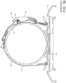
- Figure 1B shows a sectional view of the frame 12, cylinder 16, and cylinder retaining apparatus 22 along the line BB in Figure 1A , viewed longitudinally down the apparatus 10.
- the frame 12 comprises a cylinder cradle 24 which has a concave profile to receive the convex shell of the cylinder 16, and locate it in the correct position on the frame 12.
- the cylinder-retaining apparatus 22 comprises a strap apparatus 26 which forms a strap loop which extends around the cylinder 16.
- a first end of the strap apparatus 26 is secured to the frame 12 at a first fixing point 28 and a second end of the strap apparatus is secured to a second fixing point 30.
- the first and second fixing points 28 and 30 are arranged on opposing lateral sides of the cylinder cradle 24 such that the strap apparatus 26, when tightened, urges the cylinder 16 against the cradle 24.
- the strap apparatus 26 comprises main strap 32, formed in this example from a flexible webbing material, a tensioning mechanism 34, and an adjustment buckle 36.
- the main strap is looped through the adjustment buckle 36, and around an axle 38 of the tensioning mechanism 34. Accordingly, the total length of the strap apparatus 26 can be adjusted by moving the adjustment buckle 36 relative to the main strap 32.
- the tensioning mechanism 34 is released, the adjustment buckle 36 is moved towards the tensioning mechanism 34 so as to maximise the length of the strap apparatus 26.
- the cylinder 16 is placed on the frame 12 in the cylinder cradle 24.
- the adjustment buckle 36 is them moved relative to the main strap 32 towards the first fixing point 28 (i.e. away from the tensioning mechanism 34) to reduce the total length of the strap apparatus 26 such that closely fits the cylinder 16.
- the tensioning mechanism 34 is then engaged to apply tension to the strap apparatus 26, so as to retain the cylinder 24 against the cradle 24.
- this prior art cylinder retaining apparatus 22 has a small range of adjustment which permits it to retain cylinders having a range of different diameters.
- an extreme size of cylinder i.e. very large or small
- more than one cylinder is to be retained, then the adjustment provided by this apparatus will not be sufficient, and an entirely different retaining apparatus must be swapped in, which can be time consuming and inefficient.
- FIGS 2A , 2B , and 3 illustrate an exemplary embodiment in accordance with this disclosure.
- a breathing apparatus 100 is shown.
- the breathing apparatus 100 comprises a frame 102, which is wearable on a user's back using shoulder straps 104.
- the breathing apparatus 100 in this case is a self-contained breathing apparatus or "SCBA", but it should be understood that other breathing apparatus types, such as closed circuit breathing apparatus (CCBA), could apply the principles of this disclosure.
- SCBA self-contained breathing apparatus
- CCBA closed circuit breathing apparatus
- FIG. 2A shows a rear view of the breathing apparatus 100.
- the frame 102 supports two breathing gas cylinders 106 (each of which will be referred to simply as a "cylinder” for brevity in this description).
- Each cylinder 106 comprises a valve apparatus 108 at an end thereof which is attached to a respective cylinder attachment 110 provided on the lower end of the frame 102.
- the attachment 110 secures the lower end of the cylinder 106 to the frame 102.
- a manifold may be provided to join the cylinder valves 108 to a single attachment 110 provided on the frame 102.
- the cylinders 106 extends generally longitudinally along the frame 102 and side-by side.
- a cylinder-retaining apparatus 112 is provided proximate an upper end of the frame 102 to secure an upper end of each of the cylinders 106.
- the cylinder retaining apparatus 112 retains the cylinder 106 proximate an upper end of the cylinder 16, but in other examples, it may be arranged to retain the cylinders 16 at another location.
- the cylinder-retaining apparatus 112 is configured in an expanded configuration for retaining two cylinders. As will be evident from this description as a whole, the cylinder-retaining apparatus 112 can also be configured in at least one other configuration, a contracted configuration, to hold one cylinder. It should be understood that the principles of the present disclosure could be applied to construct a cylinder retaining apparatus which could retain different numbers of cylinders in its respective expanded and contracted configurations than the exemplary embodiments described here.
- Figure 2B shows a sectional view of the frame 102, cylinders 106, and cylinder retaining apparatus 112 along the line BB in Figure 2A , viewed longitudinally down the apparatus 100.
- the frame 102 comprises a cylinder cradle 114 which has a single central concave profile 114a to receive the convex shell of a single cylinder in the contracted configuration, and dual concave profiles 114b laterally spaced apart for receiving respective cylinders 106 in this expanded configuration.
- the profiles 114b serve to locate the cylinders 106 in the correct position on the frame 102.
- the cylinder-retaining apparatus 112 comprises a strap apparatus 116 which is secured at first and second ends respectively to a first fixing point 118 and a second fixing point 120 so as to form a main strap loop 128 for extending around and securing one or more cylinders.
- the strap apparatus 116 comprises a strap 122 (having length S and formed from a flexible webbing material), a tensioning mechanism 124, and an adjustment buckle 126.
- the tensioning mechanism 124 in this example is an over-centre mechanism for applying tension to the strap 122, but other tensioning mechanisms are possible.
- the strap apparatus comprises a pull-down buckle 130 which is secured to a distal end of a pull-down strap 132, as shown in detail in Figure 6 .
- the other end of the pull-down strap 132 is secured to the frame 102 at a point equidistant between the first and second fixing points 118,120.
- the pull-down strap 132 is shorter in length than the diameter of the cylinders 106 and the strap 122 extends through the pull-down buckle 130, such that the strap 122 is pulled-down between the cylinders 106 to provide additional contact of the strap 122 between the cylinders 106.
- the pull-down buckle 130 separates the main strap loop 128 into a first cylinder retaining portion 129 for securing one of the cylinders 106, and a second cylinder retaining potion 131 for securing the other of the cylinders 106.
- the portion of the strap 122 which extends around both cylinders 106 is the main strap loop 128.
- a portion of the strap 122 extends through the adjustment buckle 126 to form a secondary strap loop 134.
- the secondary strap loop 134 is essentially a folded portion of the strap 122 which is fed through the adjustment buckle 126. This folded portion of the strap 122, or secondary strap loop 134, extends around a portion of the pull-down buckle 130, which therefore maintains the secondary strap loop 134 in its folded position.
- the main strap loop may be formed by the portion of the strap 122 on one side of the adjustment buckle 126
- the secondary strap loop 128 may be formed by the portion of the strap 122 on the other side of the adjustment buckle 126.
- the portion of the strap 122 forming the secondary strap loop is doubled back on itself to form a loop of strap material. It should be understood that by configuring a portion of the strap 122 in this way, and by adjusting the relative proportion of the strap 122 which is utilised in the secondary strap loop 134, the effective length of the main strap loop 128 can be altered.
- the strap 122 is continuous, the strap is notionally divided into the main and secondary strap loops.
- the main strap loop may be the portion of the strap 122 which contacts the cylinders 106, and the secondary strap loop may be the portion of the strap which is folded to take up excess length of the strap 122 to ensure an appropriate strap length for the cylinder(s) in use.
- the main strap loop 128 is essentially divided into two parts 128a and 128b, which are formed on opposing sides of the adjustment buckle 126 and secondary strap loop 134.
- the secondary strap loop 134 is present in the expanded configuration, but it should be understood that in other examples, such as that shown in Figures 7A and 7B below, the secondary strap loop 134 may not be present in the expanded configuration.
- the main strap loop 128 provides a first effective length, L x , between the first and second fixing points for securing the two cylinders 106.
- the approximate length of the strap 122 which is utilised in the secondary strap loop 134 is twice the distance E, which is the distance between the adjustment buckle 126 and the distal end of the secondary strap loop 134 (which is defined in this example by the pull-down buckle 130).
- the effective length of the main strap loop 128 in this expanded configuration is S - (2 x E). It will be appreciated that cylinders 106 of different diameters can be accommodated in the expanded configuration by finely adjusting the distance E i.e. by moving the adjustment buckle 126 relative to the pull-down buckle 130 to adjust the amount of the strap 122 which is utilised in the secondary strap loop 134.
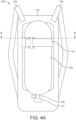
- FIG. 4A , 4B , and 5 the breathing apparatus 100 and, in particular, the cylinder-retaining apparatus 112 is shown in a contracted configuration for securing fewer cylinders than the expanded configuration.
- the secondary strap loop 134 has been extended by feeding additional length of the strap 122 through the adjustment buckle 126, and the distal end of the secondary strap loop 134 has been secured to a third fixing point 136 on the frame 102. Therefore, as a far greater proportion of the strap 122 is utilised in the secondary strap loop 134, the main strap loop 128 forms an effective length, L c , between the first and second fixing points, which is shorter than the effective length, L x , of the expanded configuration.
- the distance E (which is half the total length of the strap 122 which is utilised in the secondary strap loop 134) is defined by the distance between the third fixing point 136 and the adjustment buckle 126. Accordingly, fine adjustment of the main strap loop's 128 effective length can still be achieved by moving the adjustment buckle 126 along the strap 122 to adjust the distance E.
- the third fixing point 136 is formed by an axle pin 138.
- the axle pin 138 is retractable such that it can be retracted to attach and detach the secondary strap loop 134 when adjusting between the expanded and contracted configurations.
- the third fixing point could be any releasable fixing for securing the secondary strap loop.
- the third fixing point could alternatively be provided by an open or cut-away slot, of similar form to slot 242 described below.
- the third fixing point 136 is provided proximate the first fixing point 118.
- the third fixing point 136 could also or alternatively be provided in other locations, such as laterally outside of the first and second fixing points. More than one additional fixing point could be provided to enable a number of contracted/expanded configurations for securing different numbers of cylinders.
- the pull-down strap 132 In the contracted configuration of this example, where only one cylinder 106 is retained, the pull-down strap 132 is not required, so it can be stowed flat against the frame 102 by moving the pull-down buckle 130 to a position adjacent the first and third fixing points 118,136. As the secondary strap loop 134 is still looped around the pull-down buckle 130, a convenient way to of increase the secondary strap loop's length in the contracted configuration is to move the pull-down buckle 130 towards the third fixing point 136 relative to the main strap loop 128, as the distal end of secondary strap loop 134 will likewise be moved.
- the portion of the strap 122 which, in the expanded configuration, would have accommodated the additional second cylinder, is accommodated in the contracted configuration by the greatly expanded secondary strap loop 134.
- the secondary strap loop 134 is much larger in the contracted configuration, and loose strapping can cause a safety hazard, the securing of the secondary strap loop to the third fixing point 136 conveniently stows the excess strap material safely flat against the breathing apparatus 100.
- the invention provides a far greater range of adjustment than prior art systems by allowing a significant proportion of a long multiple-cylinder strap to be taken up in a secondary strap loop. Accordingly, a strap which can accommodate multiple cylinders can be adjusted using the principles of the present disclosure to retain fewer cylinders by taking up the excess in a secondary strap loop, which can be conveniently secured to an additional fixing point.
- the secondary strap loop Owing to the folded design of the secondary strap loop it can be configured to overlay the main strap loop, so as to minimize the profile of the breathing apparatus and avoid loose strapping which would present a snagging hazard.
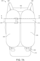
- FIG. 7A and 7B Such an example is shown in Figures 7A and 7B .
- a breathing apparatus 200 is shown.
- Like features with the example of Figures 2A and 2B are indicated with reference numerals differing by 100.
- Figure 7B shows a sectional view of the frame 202, cylinders 206, and cylinder retaining apparatus 212 along the line BB in Figure 7A , viewed longitudinally down the apparatus 200.
- the frame 202 comprises a cylinder cradle 214 which has a single central concave profile 214a to receive the convex shell of a single cylinder in the contracted configuration, and dual concave profiles 214b laterally spaced apart for receiving respective cylinders 206 in this expanded configuration.
- the profiles 214b serve to locate the cylinders 206 in the correct position on the frame 202.
- the breathing apparatus 200 comprises a cylinder-retaining apparatus 212 comprising a strap apparatus 216 which is secured at first and second ends respectively to a first fixing point 218 and a second fixing point 220 so as to form a main strap loop 228 for extending around and securing the two cylinders 206.
- the strap apparatus 216 comprises a strap 222, a tensioning mechanism 224, and an adjustment buckle 226.
- the strap apparatus 216 comprises a pull-down buckle 230 which is secured to a distal end of a pull-down strap 232.
- a secondary strap loop 234 can be formed to take up the excess strap 222 which is no longer required to encircle a second cylinder.
- the adjustment buckle 226 comprises a slot 240, and a portion of the strap 222 can be folded and inserted through the slot 240.
- the formation of the secondary strap loop 234 is illustrated by the arrow P in Figure 7B . Once the secondary strap loop 234 has been formed, it can be drawn around to the third fixing point 236 and secured so as to secure the excess strap 222.
- the pull-down buckle 230 may have a cut-away slot 242 which can releasably secure the secondary strap loop 234. Therefore, the cylinder-retaining apparatus 212 can be optionally finely adjusted in the expanded configuration for differently sized cylinders by forming a secondary strap loop 234 and securing it to the cut-away slot 242.
Landscapes
- Health & Medical Sciences (AREA)
- Pulmonology (AREA)
- General Health & Medical Sciences (AREA)
- Business, Economics & Management (AREA)
- Emergency Management (AREA)
- Engineering & Computer Science (AREA)
- Mechanical Engineering (AREA)
- Ocean & Marine Engineering (AREA)
- Respiratory Apparatuses And Protective Means (AREA)
Description
- The present disclosure relates to a cylinder-retaining apparatus for a breathing apparatus and is particularly, although not exclusively, concerned with an adjustable or cylinder strap apparatus for a breathing apparatus, such as a self-contained breathing apparatus (SCBA).
- Breathing apparatuses, such as SCBAs, comprise breathing gas cylinders which are replaceable. Such cylinders must be securely retained on the breathing apparatus, so it is known to provide a strap which retains the cylinder against a frame of the breathing apparatus.
- However, such prior art straps have a small range of adjustment which only permit them to retain cylinders having a small range of different diameters. However, if an extreme size of cylinder (i.e. very large or small) or more than one cylinder is to be retained, then the adjustment provided by prior art straps may not be sufficient, and an entirely different retaining strap must be swapped in, which can be time consuming and inefficient. Further, even if a prior art strap is sufficiently long to accommodate a wide range of different cylinders, the excess strap material which is present when securing cylinders at the lower end of its range can be difficult to manage, and can cause snagging hazards which are extremely dangerous to emergency services personnel using the breathing apparatus.
- Accordingly, it will be appreciated that improvements in cylinder-retaining straps for breathing apparatus are desirable.
-
DE 10 2013 016210 describes a carrying device for at least one pressurized gas bottle of a respirator, in which the or each compressed gas cylinder is fixable by means of a first and a second breakpoint engaging the fastening device on the carrying device and wherein the position of at least one holding point is variable. -
US 8 776 323 describes a strap assembly for securing a vehicle load including a fixed flat strap secured around a buckle crossbar and a hook attached to an end of the strap. The parts are configured such that that upon engaging the hook and crossbar there is an interference fit, allowing a major loop to be formed in the strap that will remain securely engaged even when there is slack in the strap. Additionally, the hook/buckle combination is configured such that substantially rotating the hook relative the buckle is required to disengage the two. - According to a first aspect of the present disclosure, there is provided a cylinder-retaining apparatus for a breathing apparatus as set out in the appended independent claim 1. Further optional features are set out in the appended dependent claims. The cylinder retaining apparatus as set out in the appended independent claim 1. Further optional features are set out in the appended dependent claims. The cylinder retaining apparatus comprises first and second fixing point and a strap apparatus secured to the first fixing point and the second fixing point, The strap apparatus forms a main strap loop for extending around and securing one or more cylinders. The cylinder-retaining apparatus is configurable in: i) an expanded configuration in which the main strap loop provides a first effective length for securing a first number of cylinders; and ii) a contracted configuration in which a portion of a strap of the strap apparatus is folded to form a secondary strap loop and the secondary strap loop is secured to a third fixing point such that the main strap loop forms a second effective length which is shorter than the first effective length and for securing a second number of cylinders less than the first number of cylinders.
- By 'folded' it should be understood that the portion of the strap forming the secondary strap loop is doubled back on itself to form a loop of material. It should be understood that by configuring a portion of the main strap in this way, the effective length of the main strap loop is altered. Excess material of the strap which is not in use in the main strap loop may be taken up in the secondary strap loop.
- In the expanded configuration, the strap may also be folded to form the secondary strap loop. The secondary strap loop may contains a greater length of the strap in the contracted configuration than in the expanded configuration.
- The folded portion of the strap may extend through a first buckle, thereby forming the secondary strap loop. The main strap loop may be formed by the portion of the strap on one side of the first buckle, and the secondary strap loop may be formed by the portion of the strap on the other side of the buckle.
- The cylinder-retaining apparatus may further comprise a second buckle through which the secondary strap loop extends and through which the main strap loop extends, such that when the second buckle is moved relative to the main strap loop, the secondary strap loop is moved relative to the main strap loop.
- The first and second buckles are configured such that moving the first and second buckles apart along the main strap loop shortens the effective length of the main strap loop, and moving the first and second buckles together along the main strap loop extends the effective length of the main strap loop. Where the first and second buckles are provided, it should be understood that the total length of the strap which is formed into the secondary strap loop is defined by the distance between the first and second buckles.
- A pull-down strap may extend between the frame and the second buckle. The pull-down strap may be secured to a further fixing point between the first and second fixing points. It should be understood that the pull-down strap is for the purpose of pulling a portion of the main strap loop closer to a frame of the breathing apparatus between two cylinders so as to secure multiple cylinders more securely. More than one pull-down strap may be provided if the breathing apparatus is configured to use more than two cylinders. It should be understood that the present disclosure could be applied to provide breathing apparatuses which are adjustable between single- and double-cylinder configurations, or between configurations having other numbers of cylinders in their expanded and contracted configurations.
- The second buckle may define a first portion of the main strap loop between the first fixing points and the second buckle, and a second portion of the main strap loop between the second fixing point and the second buckle. In other words, first and second portions of the main strap loop may be formed either side of the second buckle. Where a pull-down strap is provided, the first and second portions of the main strap loop may be formed on opposing sides of the pull-down strap. The first and second portions of the main strap loop may be configured to contact and secure a respective cylinder in the extended configuration.
- In the expanded configuration, the second buckle may be arranged relative to the main strap loop such that the first and second portions of the main strap loop are substantially equal in length. Accordingly, two cylinders of the same size may be secured conveniently.
- In the contracted configuration, the second buckle may arranged relative to the main strap loop proximate the second fixing point, such that the second portion of the main strap loop is substantially shorter in length than the first portion of the main strap loop. In other words, the second portion of the main strap loop may be negligible in length. In the contracted position, the secondary strap loop may overlay the main strap loop between the first buckle and the third fixing point.
- In the expanded configuration, the second portion of the main strap loop may be at least partially overlaid by the secondary strap loop.
- The second portion of the main strap loop may be overlaid by the secondary strap loop between the first and second buckles.
- The cylinder-retaining apparatus may further comprise a securing buckle for applying tension to the main strap loop.
- The third fixing point may be one or more of: i) proximate the second fixing point; ii) outside of the first and second fixing points; or iii) releasable to secure or release the secondary strap loop by hand.
- The cylinder retaining apparatus may further comprise a frame for supporting one or more breathing gas cylinders. The frame may comprise the first, second, and third fixing points.
- According to a second aspect of the present disclosure there is provided a breathing apparatus comprising a cylinder-retaining apparatus according to the first aspect described above.
- To avoid unnecessary duplication of effort and repetition of text in the specification, certain features are described in relation to only one or several aspects or embodiments of the invention. However, it is to be understood that, where it is technically possible, features described in relation to any aspect or embodiment of the invention may also be used with any other aspect or embodiment of the invention.
- For a better understanding of the present invention, and to show more clearly how it may be carried into effect, reference will now be made, by way of example, to the accompanying drawings, in which:
-
Figure 1A is a rear view of a prior art breathing apparatus; -
Figure 1B is a sectional view of the prior art breathing apparatus ofFigure 1A ; -
Figure 2A is a rear view of an exemplary breathing apparatus comprising a cylinder retaining apparatus according to the present disclosure in an expanded configuration; -
Figure 2B is a sectional view of the breathing apparatus ofFigure 2A ; -
Figure 3 is a perspective view of the cylinder retaining apparatus ofFigures 2A and2B ; -
Figure 4A is a rear view of an exemplary breathing apparatus comprising a cylinder retaining apparatus according to the present disclosure in a contracted configuration; -
Figure 4B is a sectional view of the breathing apparatus ofFigure 4A ; -
Figure 5 is a perspective view of the cylinder retaining apparatus ofFigures 4A and4B in the contracted configuration; and -
Figure 6 is a perspective view of a pull-down strap of a cylinder retaining apparatus; -
Figure 7A is a rear view of a further exemplary breathing apparatus comprising a cylinder retaining apparatus according to the present disclosure in an expanded configuration; and -
Figure 7B is a sectional view of the breathing apparatus ofFigure 7A . - In order to place the invention in context, a prior art system will be described first.
-
Figures 1A and1B illustrate a priorart breathing apparatus 10. The breathing apparatus in this case is a self-contained breathing apparatus or "SCBA". TheSCBA 10 comprises aframe 12, which is wearable on a user's back using shoulder straps 14. -
Figure 1A shows a rear view of thebreathing apparatus 10. Theframe 12 supports a breathing gas cylinder 16 (which will be referred to simply as a "cylinder" for brevity in this description). Thecylinder 16 comprises avalve apparatus 18 at an end thereof which is attached to acylinder attachment 20 provided on the lower end of theframe 12. Thisattachment 20 secures the lower end of the cylinder to theframe 12. In some examples, theattachment 20 is a pressure reduction valve provided on theframe 12 to which thecylinder valve apparatus 18 is attached. Thecylinder 16 extends generally longitudinally along theframe 12, so the upper end of the cylinder also requires retaining in order to avoid putting undue stress on theattachment 20 andvalve 18. Therefore, a cylinder-retainingapparatus 22 is provided proximate an upper end of theframe 12. In this example, thecylinder retaining apparatus 22 retains thecylinder 16 proximate an upper end of thecylinder 16, but in other examples, it may be arranged to retain thecylinder 16 at another location. - In
Figure 1B , thebreathing apparatus 10 can be observed in more detail.Figure 1B shows a sectional view of theframe 12,cylinder 16, andcylinder retaining apparatus 22 along the line BB inFigure 1A , viewed longitudinally down theapparatus 10. Theframe 12 comprises acylinder cradle 24 which has a concave profile to receive the convex shell of thecylinder 16, and locate it in the correct position on theframe 12. - The cylinder-retaining
apparatus 22 comprises astrap apparatus 26 which forms a strap loop which extends around thecylinder 16. A first end of thestrap apparatus 26 is secured to theframe 12 at afirst fixing point 28 and a second end of the strap apparatus is secured to asecond fixing point 30. The first and second fixing points 28 and 30 are arranged on opposing lateral sides of thecylinder cradle 24 such that thestrap apparatus 26, when tightened, urges thecylinder 16 against thecradle 24. - The
strap apparatus 26 comprisesmain strap 32, formed in this example from a flexible webbing material, atensioning mechanism 34, and anadjustment buckle 36. The main strap is looped through theadjustment buckle 36, and around anaxle 38 of thetensioning mechanism 34. Accordingly, the total length of thestrap apparatus 26 can be adjusted by moving theadjustment buckle 36 relative to themain strap 32. - To attach and secure the
cylinder 16 to theframe 12, thetensioning mechanism 34 is released, theadjustment buckle 36 is moved towards thetensioning mechanism 34 so as to maximise the length of thestrap apparatus 26. Next, thecylinder 16 is placed on theframe 12 in thecylinder cradle 24. Theadjustment buckle 36 is them moved relative to themain strap 32 towards the first fixing point 28 (i.e. away from the tensioning mechanism 34) to reduce the total length of thestrap apparatus 26 such that closely fits thecylinder 16. Thetensioning mechanism 34 is then engaged to apply tension to thestrap apparatus 26, so as to retain thecylinder 24 against thecradle 24. - Therefore, it will be understood that this prior art
cylinder retaining apparatus 22 has a small range of adjustment which permits it to retain cylinders having a range of different diameters. However, if an extreme size of cylinder (i.e. very large or small) or more than one cylinder is to be retained, then the adjustment provided by this apparatus will not be sufficient, and an entirely different retaining apparatus must be swapped in, which can be time consuming and inefficient. -
Figures 2A ,2B , and3 illustrate an exemplary embodiment in accordance with this disclosure. InFigures 2A and2B , abreathing apparatus 100 is shown. Thebreathing apparatus 100 comprises aframe 102, which is wearable on a user's back usingshoulder straps 104. Thebreathing apparatus 100 in this case is a self-contained breathing apparatus or "SCBA", but it should be understood that other breathing apparatus types, such as closed circuit breathing apparatus (CCBA), could apply the principles of this disclosure. -
Figure 2A shows a rear view of thebreathing apparatus 100. Theframe 102 supports two breathing gas cylinders 106 (each of which will be referred to simply as a "cylinder" for brevity in this description). Eachcylinder 106 comprises avalve apparatus 108 at an end thereof which is attached to arespective cylinder attachment 110 provided on the lower end of theframe 102. Theattachment 110 secures the lower end of thecylinder 106 to theframe 102. In other examples, a manifold may be provided to join thecylinder valves 108 to asingle attachment 110 provided on theframe 102. - The
cylinders 106 extends generally longitudinally along theframe 102 and side-by side. A cylinder-retainingapparatus 112 is provided proximate an upper end of theframe 102 to secure an upper end of each of thecylinders 106. In this example, thecylinder retaining apparatus 112 retains thecylinder 106 proximate an upper end of thecylinder 16, but in other examples, it may be arranged to retain thecylinders 16 at another location. - It is important to appreciate that, in
Figures 2A ,2B , and3 , the cylinder-retainingapparatus 112 is configured in an expanded configuration for retaining two cylinders. As will be evident from this description as a whole, the cylinder-retainingapparatus 112 can also be configured in at least one other configuration, a contracted configuration, to hold one cylinder. It should be understood that the principles of the present disclosure could be applied to construct a cylinder retaining apparatus which could retain different numbers of cylinders in its respective expanded and contracted configurations than the exemplary embodiments described here. - In
Figure 2B , thebreathing apparatus 100 can be observed in more detail.Figure 2B shows a sectional view of theframe 102,cylinders 106, andcylinder retaining apparatus 112 along the line BB inFigure 2A , viewed longitudinally down theapparatus 100. Theframe 102 comprises a cylinder cradle 114 which has a single centralconcave profile 114a to receive the convex shell of a single cylinder in the contracted configuration, and dualconcave profiles 114b laterally spaced apart for receivingrespective cylinders 106 in this expanded configuration. Theprofiles 114b serve to locate thecylinders 106 in the correct position on theframe 102. - The cylinder-retaining
apparatus 112 comprises astrap apparatus 116 which is secured at first and second ends respectively to afirst fixing point 118 and asecond fixing point 120 so as to form amain strap loop 128 for extending around and securing one or more cylinders. Thestrap apparatus 116 comprises a strap 122 (having length S and formed from a flexible webbing material), atensioning mechanism 124, and anadjustment buckle 126. Thetensioning mechanism 124 in this example is an over-centre mechanism for applying tension to thestrap 122, but other tensioning mechanisms are possible. - Additionally, the strap apparatus comprises a pull-
down buckle 130 which is secured to a distal end of a pull-downstrap 132, as shown in detail inFigure 6 . The other end of the pull-downstrap 132 is secured to theframe 102 at a point equidistant between the first and second fixing points 118,120. The pull-downstrap 132 is shorter in length than the diameter of thecylinders 106 and thestrap 122 extends through the pull-down buckle 130, such that thestrap 122 is pulled-down between thecylinders 106 to provide additional contact of thestrap 122 between thecylinders 106. The pull-down buckle 130 separates themain strap loop 128 into a firstcylinder retaining portion 129 for securing one of thecylinders 106, and a secondcylinder retaining potion 131 for securing the other of thecylinders 106. - The portion of the
strap 122 which extends around bothcylinders 106 is themain strap loop 128. As can be observed inFigure 2B , a portion of thestrap 122 extends through theadjustment buckle 126 to form asecondary strap loop 134. Thesecondary strap loop 134 is essentially a folded portion of thestrap 122 which is fed through theadjustment buckle 126. This folded portion of thestrap 122, orsecondary strap loop 134, extends around a portion of the pull-down buckle 130, which therefore maintains thesecondary strap loop 134 in its folded position. The main strap loop may be formed by the portion of thestrap 122 on one side of theadjustment buckle 126, and thesecondary strap loop 128 may be formed by the portion of thestrap 122 on the other side of theadjustment buckle 126. - By 'folded', it should be understood that the portion of the
strap 122 forming the secondary strap loop is doubled back on itself to form a loop of strap material. It should be understood that by configuring a portion of thestrap 122 in this way, and by adjusting the relative proportion of thestrap 122 which is utilised in thesecondary strap loop 134, the effective length of themain strap loop 128 can be altered. - It should be understood that, although the
strap 122 is continuous, the strap is notionally divided into the main and secondary strap loops. The main strap loop may be the portion of thestrap 122 which contacts thecylinders 106, and the secondary strap loop may be the portion of the strap which is folded to take up excess length of thestrap 122 to ensure an appropriate strap length for the cylinder(s) in use. As can be seen inFigure 2B , themain strap loop 128 is essentially divided into twoparts adjustment buckle 126 andsecondary strap loop 134. In this exemplary embodiment, thesecondary strap loop 134 is present in the expanded configuration, but it should be understood that in other examples, such as that shown inFigures 7A and7B below, thesecondary strap loop 134 may not be present in the expanded configuration. - In this expanded configuration shown in
Figures 2A ,2B , and3 , themain strap loop 128 provides a first effective length, Lx, between the first and second fixing points for securing the twocylinders 106. The approximate length of thestrap 122 which is utilised in thesecondary strap loop 134 is twice the distance E, which is the distance between theadjustment buckle 126 and the distal end of the secondary strap loop 134 (which is defined in this example by the pull-down buckle 130). Accordingly, the effective length of themain strap loop 128 in this expanded configuration is S - (2 x E). It will be appreciated thatcylinders 106 of different diameters can be accommodated in the expanded configuration by finely adjusting the distance E i.e. by moving theadjustment buckle 126 relative to the pull-down buckle 130 to adjust the amount of thestrap 122 which is utilised in thesecondary strap loop 134. - However, when changing from a dual-cylinder configuration to a single-cylinder configuration is required, a more substantial adjustment of the cylinder-retaining
apparatus 112 is required. - Turning now to
Figures 4A ,4B , and5 , thebreathing apparatus 100 and, in particular, the cylinder-retainingapparatus 112 is shown in a contracted configuration for securing fewer cylinders than the expanded configuration. - As can be observed in
Figure 4B , the excess portion of thestrap 122 which is folded to form thesecondary strap loop 128 is far longer in this contracted configuration. - In the contracted configuration of
Figure 4B , thesecondary strap loop 134 has been extended by feeding additional length of thestrap 122 through theadjustment buckle 126, and the distal end of thesecondary strap loop 134 has been secured to athird fixing point 136 on theframe 102. Therefore, as a far greater proportion of thestrap 122 is utilised in thesecondary strap loop 134, themain strap loop 128 forms an effective length, Lc, between the first and second fixing points, which is shorter than the effective length, Lx, of the expanded configuration. - In the contracted configuration shown, the distance E (which is half the total length of the
strap 122 which is utilised in the secondary strap loop 134) is defined by the distance between thethird fixing point 136 and theadjustment buckle 126. Accordingly, fine adjustment of the main strap loop's 128 effective length can still be achieved by moving theadjustment buckle 126 along thestrap 122 to adjust the distance E. - As can be observed in
Figure 5 , thethird fixing point 136 is formed by anaxle pin 138. Theaxle pin 138 is retractable such that it can be retracted to attach and detach thesecondary strap loop 134 when adjusting between the expanded and contracted configurations. In other examples, the third fixing point could be any releasable fixing for securing the secondary strap loop. For example, the third fixing point could alternatively be provided by an open or cut-away slot, of similar form to slot 242 described below. - In this example, the
third fixing point 136 is provided proximate thefirst fixing point 118. Thethird fixing point 136 could also or alternatively be provided in other locations, such as laterally outside of the first and second fixing points. More than one additional fixing point could be provided to enable a number of contracted/expanded configurations for securing different numbers of cylinders. - In the contracted configuration of this example, where only one
cylinder 106 is retained, the pull-downstrap 132 is not required, so it can be stowed flat against theframe 102 by moving the pull-down buckle 130 to a position adjacent the first and third fixing points 118,136. As thesecondary strap loop 134 is still looped around the pull-down buckle 130, a convenient way to of increase the secondary strap loop's length in the contracted configuration is to move the pull-down buckle 130 towards thethird fixing point 136 relative to themain strap loop 128, as the distal end ofsecondary strap loop 134 will likewise be moved. - Overall, it should be understood that the portion of the
strap 122 which, in the expanded configuration, would have accommodated the additional second cylinder, is accommodated in the contracted configuration by the greatly expandedsecondary strap loop 134. As thesecondary strap loop 134 is much larger in the contracted configuration, and loose strapping can cause a safety hazard, the securing of the secondary strap loop to thethird fixing point 136 conveniently stows the excess strap material safely flat against thebreathing apparatus 100. - The invention provides a far greater range of adjustment than prior art systems by allowing a significant proportion of a long multiple-cylinder strap to be taken up in a secondary strap loop. Accordingly, a strap which can accommodate multiple cylinders can be adjusted using the principles of the present disclosure to retain fewer cylinders by taking up the excess in a secondary strap loop, which can be conveniently secured to an additional fixing point.
- Owing to the folded design of the secondary strap loop it can be configured to overlay the main strap loop, so as to minimize the profile of the breathing apparatus and avoid loose strapping which would present a snagging hazard.
- It should be appreciated that, although the above exemplary embodiment has a secondary strap loop formed in both the expanded and contracted configurations, in some examples, there may be no secondary strap loop formed in the expanded configuration. Such an example is shown in
Figures 7A and7B . Here, abreathing apparatus 200 is shown. Like features with the example ofFigures 2A and2B are indicated with reference numerals differing by 100. - In
Figure 7B , thebreathing apparatus 200 can be observed in more detail.Figure 7B shows a sectional view of theframe 202,cylinders 206, andcylinder retaining apparatus 212 along the line BB inFigure 7A , viewed longitudinally down theapparatus 200. Theframe 202 comprises a cylinder cradle 214 which has a single centralconcave profile 214a to receive the convex shell of a single cylinder in the contracted configuration, and dualconcave profiles 214b laterally spaced apart for receivingrespective cylinders 206 in this expanded configuration. Theprofiles 214b serve to locate thecylinders 206 in the correct position on theframe 202. - The
breathing apparatus 200 comprises a cylinder-retainingapparatus 212 comprising a strap apparatus 216 which is secured at first and second ends respectively to afirst fixing point 218 and asecond fixing point 220 so as to form amain strap loop 228 for extending around and securing the twocylinders 206. The strap apparatus 216 comprises astrap 222, atensioning mechanism 224, and anadjustment buckle 226. In addition, the strap apparatus 216 comprises a pull-down buckle 230 which is secured to a distal end of a pull-downstrap 232. - As can be observed in
Figure 7B , while thestrap 222 extends through theadjustment buckle 226, it is not formed into a secondary strap loop like the example ofFigure 2B . Therefore, the strap apparatus 216 is in its longest-possible configuration inFigure 7B for securing large cylinders. - In order to adjust the cylinder-retaining
apparatus 212 to secure a single cylinder only, asecondary strap loop 234 can be formed to take up theexcess strap 222 which is no longer required to encircle a second cylinder. Theadjustment buckle 226 comprises aslot 240, and a portion of thestrap 222 can be folded and inserted through theslot 240. The formation of thesecondary strap loop 234 is illustrated by the arrow P inFigure 7B . Once thesecondary strap loop 234 has been formed, it can be drawn around to thethird fixing point 236 and secured so as to secure theexcess strap 222. - As shown in
Figure 6 , the pull-down buckle 230 may have a cut-away slot 242 which can releasably secure thesecondary strap loop 234. Therefore, the cylinder-retainingapparatus 212 can be optionally finely adjusted in the expanded configuration for differently sized cylinders by forming asecondary strap loop 234 and securing it to the cut-away slot 242. - It will be appreciated by a skilled person that although the invention has been described by way of example, with reference to exemplary examples, it is not limited to the disclosed examples and that alternative examples could be constructed without departing from the scope of the invention as defined by the appended claims.
Claims (11)
- A cylinder-retaining apparatus (112, 212) for a breathing apparatus (100, 200) comprising:a support frame comprising a cylinder cradle having a single central concave profile and dual laterally spaced concave profiles arranged on either side of the single central concave profile, a first fixing point arranged at a first lateral side of the single central concave profile, a second fixing point (118, 120, 218, 220) arranged at a second opposing lateral side of the single central concave profile, and a third, releasable fixing point on the support frame of a breathing apparatus, the third fixing point being located laterally outside of the first and second fixing points (118, 120, 218, 220) at the first or second lateral side of the single central concave profile and proximate to one of the first and second fixing points (118, 120, 218, 220), anda strap apparatus (116, 216) comprising a strap and a first buckle (126, 226), the strap (116, 216) being secured at a first end to the first fixing point (118, 218) and at a second end the second fixing point (120, 220), the strap apparatus forming a main strap loop (128, 228) for extending around and securing one or more cylinders (106, 206), the strap apparatus (116, 216) being configurable in:i) an expanded configuration in which the main strap loop (128, 228) forms a first effective length for securing a first number of cylinders (106, 206); andii) a contracted configuration in which a portion of a strap (122, 222) of the strap apparatus (116, 216) is folded to form a secondary strap loop (134, 234), the folded portion of the strap extending through the first buckle, thereby forming the secondary strap loop, and in which the secondary strap loop is secured to the third fixing point (136, 236) such that the main strap loop (128, 228) forms a second effective length shorter than the first effective length for securing a second number of cylinders (106, 206) less than the first number of cylinders (106, 206), and wherein the secondary strap loop (134, 234) is configured to at least partially overlay the main strap loop between the first buckle and the third fixing point,wherein, in the contracted configuration the single concave profile of the cylinder cradle is configured to receive a single cylinder, and in the expanded configuration the dual concave profiles of the cylinder cradle are configured to receive respective first and second cylinders.
- A cylinder-retaining apparatus (112, 212) as claimed in claim 1, wherein:in the expanded configuration, the strap (122, 222) is also folded to form the secondary strap loop (134, 234); andwherein the secondary strap loop (134, 234) contains a greater length of the strap (122, 222) in the contracted configuration than in the expanded configuration.
- A cylinder-retaining apparatus (112, 212) as claimed in claim 1 or 2, further comprising a second buckle (130) through which the secondary strap loop extends and through which the main strap loop (128, 228) extends, such that when the second buckle (130) is moved relative to the main strap loop (128, 228), the secondary strap loop is moved relative to the main strap loop (128, 228).
- A cylinder-retaining apparatus (112, 212) as claimed in claim 3, wherein the first and second buckles (126, 130) are configured such that moving the first and second buckles apart along the main strap loop (128, 228) shortens the effective length of the main strap loop (128, 228), and moving the first and second buckles (126, 130) together along the main strap loop (128, 228) extends the effective length of the main strap loop (128, 228).
- A cylinder-retaining apparatus (112, 212) as claimed in claim 3 or 4, wherein a pull-down strap (132, 232) extends between the frame (102, 202) and the second buckle (130).
- A cylinder-retaining apparatus (112, 212) as claimed in any one of claims 3-5, wherein the second buckle (130) defines a first portion of the main strap loop (128, 228) between the first fixing points (118, 218) and the second buckle (130), and a second portion of the main strap loop (128, 228) between the second fixing point (120, 220) and the second buckle (130).
- A cylinder-retaining apparatus (112, 212) as claimed in claim 6, wherein, in the expanded configuration, the second buckle (130) is arranged relative to the main strap loop (128, 228) such that the first and second portions of the main strap loop (128, 228) are substantially equal in length.
- A cylinder-retaining apparatus (112, 212) as claimed in claim 6 or 7, wherein, in the contracted configuration, the second buckle (130) is arranged relative to the main strap loop (128, 228) proximate the first fixing point (118, 218), such that the first portion of the main strap loop (128, 228) is substantially shorter in length than the second portion of the main strap loop (128, 228).
- A cylinder-retaining apparatus (112, 212) as claimed in any one of claims 6-8, wherein, in the expanded configuration, the main strap loop (128, 228) is at least partially overlaid by the secondary strap loop.
- A cylinder-retaining apparatus (112, 212) as claimed in claim 9, wherein the second portion of the main strap loop (128, 228) is overlaid by the secondary strap loop between the first and second buckles (126, 130).
- A cylinder-retaining apparatus (112, 212) as claimed in any preceding claim, further comprising a securing buckle (124) for applying tension to the main strap loop (128, 228).
Priority Applications (4)
| Application Number | Priority Date | Filing Date | Title |
|---|---|---|---|
| EP20159485.0A EP3871739B1 (en) | 2020-02-26 | 2020-02-26 | Cylinder-retaining apparatus for a breathing apparatus |
| US17/147,890 US12024337B2 (en) | 2020-02-26 | 2021-01-13 | Cylinder-retaining apparatus for a breathing apparatus |
| CN202110169483.8A CN113304411B (en) | 2020-02-26 | 2021-02-07 | Cylinder holding equipment for respiratory equipment |
| GB2102185.2A GB2593808B (en) | 2020-02-26 | 2021-02-16 | Cylinder-retaining apparatus for a breathing apparatus |
Applications Claiming Priority (1)
| Application Number | Priority Date | Filing Date | Title |
|---|---|---|---|
| EP20159485.0A EP3871739B1 (en) | 2020-02-26 | 2020-02-26 | Cylinder-retaining apparatus for a breathing apparatus |
Publications (2)
| Publication Number | Publication Date |
|---|---|
| EP3871739A1 EP3871739A1 (en) | 2021-09-01 |
| EP3871739B1 true EP3871739B1 (en) | 2024-12-18 |
Family
ID=69902979
Family Applications (1)
| Application Number | Title | Priority Date | Filing Date |
|---|---|---|---|
| EP20159485.0A Active EP3871739B1 (en) | 2020-02-26 | 2020-02-26 | Cylinder-retaining apparatus for a breathing apparatus |
Country Status (4)
| Country | Link |
|---|---|
| US (1) | US12024337B2 (en) |
| EP (1) | EP3871739B1 (en) |
| CN (1) | CN113304411B (en) |
| GB (1) | GB2593808B (en) |
Families Citing this family (2)
| Publication number | Priority date | Publication date | Assignee | Title |
|---|---|---|---|---|
| GB2614883A (en) * | 2022-01-19 | 2023-07-26 | Draeger Safety Ag & Co Kgaa | Modular support system |
| EP4292668A1 (en) | 2022-06-16 | 2023-12-20 | Dräger Safety AG & Co. KGaA | Support frame for a breathing apparatus |
Family Cites Families (14)
| Publication number | Priority date | Publication date | Assignee | Title |
|---|---|---|---|---|
| DE240140C (en) | ||||
| US3191828A (en) * | 1962-05-14 | 1965-06-29 | Voit Rubber Corp | Harness for gas-filled cylinders |
| US3957183A (en) * | 1974-03-14 | 1976-05-18 | U.S. Divers Company | Backpack for breathing tanks |
| DE3342202C2 (en) | 1983-11-23 | 1985-10-03 | Interspiro GmbH, 7521 Forst | Carrying device for breathing gas bottles |
| DD240140A1 (en) * | 1985-08-13 | 1986-10-22 | Medizin Labortechnik Veb K | ATOMIZED GAS BOTTLE MOUNTING FOR COMPRESSED AIR EQUIPMENT |
| DE3540516A1 (en) | 1985-11-15 | 1987-05-21 | Auergesellschaft Gmbh | Compressed-air breathing apparatus |
| FR2694871B1 (en) * | 1992-08-21 | 1994-10-07 | Spirotechnique Indus Commercia | Belt structure, especially for wearing accessories. |
| GB2470023B (en) | 2009-05-06 | 2015-03-18 | Draeger Safety Uk Ltd | Gas-cylinder retaining assembly |
| DE102009024674B3 (en) | 2009-06-12 | 2010-08-26 | Dräger Safety AG & Co. KGaA | Fastening device for at least one compressed gas cylinder of a breathing apparatus |
| JP5522526B2 (en) | 2010-03-31 | 2014-06-18 | 山本光学株式会社 | Belt length adjuster |
| US8776323B2 (en) * | 2010-10-29 | 2014-07-15 | Richard E. McLennan | Cargo strap |
| DE102013016210B4 (en) * | 2013-09-28 | 2017-04-27 | Dräger Safety AG & Co. KGaA | Carrying device for at least one compressed gas cylinder |
| US9889911B1 (en) * | 2016-09-22 | 2018-02-13 | Johnson Outdoors Inc. | Back pack cinch |
| GB2573332B (en) | 2018-05-04 | 2022-05-04 | Draeger Safety Uk Ltd | Back plate for a breathing apparatus |
-
2020
- 2020-02-26 EP EP20159485.0A patent/EP3871739B1/en active Active
-
2021
- 2021-01-13 US US17/147,890 patent/US12024337B2/en active Active
- 2021-02-07 CN CN202110169483.8A patent/CN113304411B/en active Active
- 2021-02-16 GB GB2102185.2A patent/GB2593808B/en active Active
Also Published As
| Publication number | Publication date |
|---|---|
| CN113304411A (en) | 2021-08-27 |
| US20210261299A1 (en) | 2021-08-26 |
| GB2593808B (en) | 2022-10-19 |
| EP3871739A1 (en) | 2021-09-01 |
| CN113304411B (en) | 2024-04-02 |
| US12024337B2 (en) | 2024-07-02 |
| GB2593808A (en) | 2021-10-06 |
| GB202102185D0 (en) | 2021-03-31 |
Similar Documents
| Publication | Publication Date | Title |
|---|---|---|
| CN105899168B (en) | Low back extension harness with tensioning system | |
| CN206372076U (en) | Surfboard accessory for surfboard retention and emergency medical treatment | |
| US8517636B2 (en) | Gas-cylinder retaining assembly | |
| CN101879359B (en) | Harness for breathing apparatus | |
| US6681973B2 (en) | Extendable waistbelt system | |
| US6283248B1 (en) | Compact climbing harness | |
| US8622268B2 (en) | Structural support member for a harness for breathing apparatus | |
| EP3824956B1 (en) | Apparatuses for providing fall protection systems | |
| US12024337B2 (en) | Cylinder-retaining apparatus for a breathing apparatus | |
| US5285555A (en) | Adjuster buckle with locking means | |
| US5562326A (en) | Personal body restraint device | |
| US11071371B2 (en) | One-belt harness | |
| EP0570009B1 (en) | Backpack harness and cinch ring | |
| US20230371957A1 (en) | Holster and Tourniquet | |
| US11730488B2 (en) | Holster and tourniquet device and method of use | |
| US6527082B1 (en) | Attachment ring assembly for a safety harness and method of attaching an attachment ring to a safety harness | |
| US20080115332A1 (en) | Retaining System for Removably Retaining Portable Objects on a Carrier Object | |
| US6691351B1 (en) | Body immobilizing harness for spine protective carriers | |
| US12365428B2 (en) | Support frame for a breathing apparatus | |
| US9610882B1 (en) | Vehicle wheelchair restraint system | |
| US20240375575A1 (en) | Cargo securing strap devices | |
| GB2288125A (en) | Stretcher for assembly around patient with supporting straps | |
| KR102159702B1 (en) | Backpack waist belt usable as arm sling | |
| US10098418B1 (en) | Buckle capable of fixing folded strap | |
| HK1157155A1 (en) | Container holder with fasteners |
Legal Events
| Date | Code | Title | Description |
|---|---|---|---|
| PUAI | Public reference made under article 153(3) epc to a published international application that has entered the european phase |
Free format text: ORIGINAL CODE: 0009012 |
|
| STAA | Information on the status of an ep patent application or granted ep patent |
Free format text: STATUS: THE APPLICATION HAS BEEN PUBLISHED |
|
| AK | Designated contracting states |
Kind code of ref document: A1 Designated state(s): AL AT BE BG CH CY CZ DE DK EE ES FI FR GB GR HR HU IE IS IT LI LT LU LV MC MK MT NL NO PL PT RO RS SE SI SK SM TR |
|
| STAA | Information on the status of an ep patent application or granted ep patent |
Free format text: STATUS: REQUEST FOR EXAMINATION WAS MADE |
|
| 17P | Request for examination filed |
Effective date: 20220301 |
|
| RBV | Designated contracting states (corrected) |
Designated state(s): AL AT BE BG CH CY CZ DE DK EE ES FI FR GB GR HR HU IE IS IT LI LT LU LV MC MK MT NL NO PL PT RO RS SE SI SK SM TR |
|
| STAA | Information on the status of an ep patent application or granted ep patent |
Free format text: STATUS: EXAMINATION IS IN PROGRESS |
|
| 17Q | First examination report despatched |
Effective date: 20230203 |
|
| GRAP | Despatch of communication of intention to grant a patent |
Free format text: ORIGINAL CODE: EPIDOSNIGR1 |
|
| STAA | Information on the status of an ep patent application or granted ep patent |
Free format text: STATUS: GRANT OF PATENT IS INTENDED |
|
| INTG | Intention to grant announced |
Effective date: 20240726 |
|
| GRAS | Grant fee paid |
Free format text: ORIGINAL CODE: EPIDOSNIGR3 |
|
| GRAA | (expected) grant |
Free format text: ORIGINAL CODE: 0009210 |
|
| STAA | Information on the status of an ep patent application or granted ep patent |
Free format text: STATUS: THE PATENT HAS BEEN GRANTED |
|
| AK | Designated contracting states |
Kind code of ref document: B1 Designated state(s): AL AT BE BG CH CY CZ DE DK EE ES FI FR GR HR HU IE IS IT LI LT LU LV MC MK MT NL NO PL PT RO RS SE SI SK SM TR |
|
| RBV | Designated contracting states (corrected) |
Designated state(s): AL AT BE BG CH CY CZ DE DK EE ES FI FR GR HR HU IE IS IT LI LT LU LV MC MK MT NL NO PL PT RO RS SE SI SK SM TR |
|
| REG | Reference to a national code |
Ref country code: CH Ref legal event code: EP |
|
| REG | Reference to a national code |
Ref country code: DE Ref legal event code: R096 Ref document number: 602020043219 Country of ref document: DE |
|
| REG | Reference to a national code |
Ref country code: IE Ref legal event code: FG4D |
|
| REG | Reference to a national code |
Ref country code: NL Ref legal event code: FP |
|
| REG | Reference to a national code |
Ref country code: LT Ref legal event code: MG9D |
|
| PG25 | Lapsed in a contracting state [announced via postgrant information from national office to epo] |
Ref country code: HR Free format text: LAPSE BECAUSE OF FAILURE TO SUBMIT A TRANSLATION OF THE DESCRIPTION OR TO PAY THE FEE WITHIN THE PRESCRIBED TIME-LIMIT Effective date: 20241218 |
|
| PG25 | Lapsed in a contracting state [announced via postgrant information from national office to epo] |
Ref country code: FI Free format text: LAPSE BECAUSE OF FAILURE TO SUBMIT A TRANSLATION OF THE DESCRIPTION OR TO PAY THE FEE WITHIN THE PRESCRIBED TIME-LIMIT Effective date: 20241218 |
|
| PG25 | Lapsed in a contracting state [announced via postgrant information from national office to epo] |
Ref country code: BG Free format text: LAPSE BECAUSE OF FAILURE TO SUBMIT A TRANSLATION OF THE DESCRIPTION OR TO PAY THE FEE WITHIN THE PRESCRIBED TIME-LIMIT Effective date: 20241218 |
|
| PG25 | Lapsed in a contracting state [announced via postgrant information from national office to epo] |
Ref country code: NO Free format text: LAPSE BECAUSE OF FAILURE TO SUBMIT A TRANSLATION OF THE DESCRIPTION OR TO PAY THE FEE WITHIN THE PRESCRIBED TIME-LIMIT Effective date: 20250318 |
|
| PG25 | Lapsed in a contracting state [announced via postgrant information from national office to epo] |
Ref country code: LV Free format text: LAPSE BECAUSE OF FAILURE TO SUBMIT A TRANSLATION OF THE DESCRIPTION OR TO PAY THE FEE WITHIN THE PRESCRIBED TIME-LIMIT Effective date: 20241218 Ref country code: GR Free format text: LAPSE BECAUSE OF FAILURE TO SUBMIT A TRANSLATION OF THE DESCRIPTION OR TO PAY THE FEE WITHIN THE PRESCRIBED TIME-LIMIT Effective date: 20250319 |
|
| PG25 | Lapsed in a contracting state [announced via postgrant information from national office to epo] |
Ref country code: RS Free format text: LAPSE BECAUSE OF FAILURE TO SUBMIT A TRANSLATION OF THE DESCRIPTION OR TO PAY THE FEE WITHIN THE PRESCRIBED TIME-LIMIT Effective date: 20250318 |
|
| REG | Reference to a national code |
Ref country code: AT Ref legal event code: MK05 Ref document number: 1751785 Country of ref document: AT Kind code of ref document: T Effective date: 20241218 |
|
| PG25 | Lapsed in a contracting state [announced via postgrant information from national office to epo] |
Ref country code: SM Free format text: LAPSE BECAUSE OF FAILURE TO SUBMIT A TRANSLATION OF THE DESCRIPTION OR TO PAY THE FEE WITHIN THE PRESCRIBED TIME-LIMIT Effective date: 20241218 |
|
| PG25 | Lapsed in a contracting state [announced via postgrant information from national office to epo] |
Ref country code: PL Free format text: LAPSE BECAUSE OF FAILURE TO SUBMIT A TRANSLATION OF THE DESCRIPTION OR TO PAY THE FEE WITHIN THE PRESCRIBED TIME-LIMIT Effective date: 20241218 |
|
| PG25 | Lapsed in a contracting state [announced via postgrant information from national office to epo] |
Ref country code: ES Free format text: LAPSE BECAUSE OF FAILURE TO SUBMIT A TRANSLATION OF THE DESCRIPTION OR TO PAY THE FEE WITHIN THE PRESCRIBED TIME-LIMIT Effective date: 20241218 |
|
| PG25 | Lapsed in a contracting state [announced via postgrant information from national office to epo] |
Ref country code: IS Free format text: LAPSE BECAUSE OF FAILURE TO SUBMIT A TRANSLATION OF THE DESCRIPTION OR TO PAY THE FEE WITHIN THE PRESCRIBED TIME-LIMIT Effective date: 20250418 |
|
| PG25 | Lapsed in a contracting state [announced via postgrant information from national office to epo] |
Ref country code: PT Free format text: LAPSE BECAUSE OF FAILURE TO SUBMIT A TRANSLATION OF THE DESCRIPTION OR TO PAY THE FEE WITHIN THE PRESCRIBED TIME-LIMIT Effective date: 20250421 |
|
| PG25 | Lapsed in a contracting state [announced via postgrant information from national office to epo] |
Ref country code: EE Free format text: LAPSE BECAUSE OF FAILURE TO SUBMIT A TRANSLATION OF THE DESCRIPTION OR TO PAY THE FEE WITHIN THE PRESCRIBED TIME-LIMIT Effective date: 20241218 |
|
| PG25 | Lapsed in a contracting state [announced via postgrant information from national office to epo] |
Ref country code: RO Free format text: LAPSE BECAUSE OF FAILURE TO SUBMIT A TRANSLATION OF THE DESCRIPTION OR TO PAY THE FEE WITHIN THE PRESCRIBED TIME-LIMIT Effective date: 20241218 Ref country code: AT Free format text: LAPSE BECAUSE OF FAILURE TO SUBMIT A TRANSLATION OF THE DESCRIPTION OR TO PAY THE FEE WITHIN THE PRESCRIBED TIME-LIMIT Effective date: 20241218 |
|
| PG25 | Lapsed in a contracting state [announced via postgrant information from national office to epo] |
Ref country code: SK Free format text: LAPSE BECAUSE OF FAILURE TO SUBMIT A TRANSLATION OF THE DESCRIPTION OR TO PAY THE FEE WITHIN THE PRESCRIBED TIME-LIMIT Effective date: 20241218 |
|
| PG25 | Lapsed in a contracting state [announced via postgrant information from national office to epo] |
Ref country code: CZ Free format text: LAPSE BECAUSE OF FAILURE TO SUBMIT A TRANSLATION OF THE DESCRIPTION OR TO PAY THE FEE WITHIN THE PRESCRIBED TIME-LIMIT Effective date: 20241218 |
|
| PG25 | Lapsed in a contracting state [announced via postgrant information from national office to epo] |
Ref country code: IT Free format text: LAPSE BECAUSE OF FAILURE TO SUBMIT A TRANSLATION OF THE DESCRIPTION OR TO PAY THE FEE WITHIN THE PRESCRIBED TIME-LIMIT Effective date: 20241218 |
|
| PG25 | Lapsed in a contracting state [announced via postgrant information from national office to epo] |
Ref country code: SE Free format text: LAPSE BECAUSE OF FAILURE TO SUBMIT A TRANSLATION OF THE DESCRIPTION OR TO PAY THE FEE WITHIN THE PRESCRIBED TIME-LIMIT Effective date: 20241218 |
|
| PG25 | Lapsed in a contracting state [announced via postgrant information from national office to epo] |
Ref country code: MC Free format text: LAPSE BECAUSE OF FAILURE TO SUBMIT A TRANSLATION OF THE DESCRIPTION OR TO PAY THE FEE WITHIN THE PRESCRIBED TIME-LIMIT Effective date: 20241218 |
|
| REG | Reference to a national code |
Ref country code: DE Ref legal event code: R097 Ref document number: 602020043219 Country of ref document: DE |
|
| REG | Reference to a national code |
Ref country code: CH Ref legal event code: PL |
|
| PG25 | Lapsed in a contracting state [announced via postgrant information from national office to epo] |
Ref country code: DK Free format text: LAPSE BECAUSE OF FAILURE TO SUBMIT A TRANSLATION OF THE DESCRIPTION OR TO PAY THE FEE WITHIN THE PRESCRIBED TIME-LIMIT Effective date: 20241218 |
|
| PG25 | Lapsed in a contracting state [announced via postgrant information from national office to epo] |
Ref country code: LU Free format text: LAPSE BECAUSE OF NON-PAYMENT OF DUE FEES Effective date: 20250226 |
|
| PG25 | Lapsed in a contracting state [announced via postgrant information from national office to epo] |
Ref country code: CH Free format text: LAPSE BECAUSE OF NON-PAYMENT OF DUE FEES Effective date: 20250228 |
|
| PLBE | No opposition filed within time limit |
Free format text: ORIGINAL CODE: 0009261 |
|
| STAA | Information on the status of an ep patent application or granted ep patent |
Free format text: STATUS: NO OPPOSITION FILED WITHIN TIME LIMIT |
|
| 26N | No opposition filed |
Effective date: 20250919 |
|
| REG | Reference to a national code |
Ref country code: BE Ref legal event code: MM Effective date: 20250228 |
|
| PG25 | Lapsed in a contracting state [announced via postgrant information from national office to epo] |
Ref country code: BE Free format text: LAPSE BECAUSE OF NON-PAYMENT OF DUE FEES Effective date: 20250228 |
|
| PG25 | Lapsed in a contracting state [announced via postgrant information from national office to epo] |
Ref country code: IE Free format text: LAPSE BECAUSE OF NON-PAYMENT OF DUE FEES Effective date: 20250226 |
|
| PGFP | Annual fee paid to national office [announced via postgrant information from national office to epo] |
Ref country code: NL Payment date: 20260226 Year of fee payment: 7 |
|
| PGFP | Annual fee paid to national office [announced via postgrant information from national office to epo] |
Ref country code: DE Payment date: 20260226 Year of fee payment: 7 |
|
| PGFP | Annual fee paid to national office [announced via postgrant information from national office to epo] |
Ref country code: FR Payment date: 20260122 Year of fee payment: 7 |