EP3871737A1 - Method for producing a lens and ultrasound device comprising the lens - Google Patents
Method for producing a lens and ultrasound device comprising the lens Download PDFInfo
- Publication number
- EP3871737A1 EP3871737A1 EP19876539.8A EP19876539A EP3871737A1 EP 3871737 A1 EP3871737 A1 EP 3871737A1 EP 19876539 A EP19876539 A EP 19876539A EP 3871737 A1 EP3871737 A1 EP 3871737A1
- Authority
- EP
- European Patent Office
- Prior art keywords
- wave
- lens
- spherical
- nodes
- amplitude
- Prior art date
- Legal status (The legal status is an assumption and is not a legal conclusion. Google has not performed a legal analysis and makes no representation as to the accuracy of the status listed.)
- Granted
Links
Images


Classifications
-
- G—PHYSICS
- G01—MEASURING; TESTING
- G01N—INVESTIGATING OR ANALYSING MATERIALS BY DETERMINING THEIR CHEMICAL OR PHYSICAL PROPERTIES
- G01N29/00—Investigating or analysing materials by the use of ultrasonic, sonic or infrasonic waves; Visualisation of the interior of objects by transmitting ultrasonic or sonic waves through the object
- G01N29/04—Analysing solids
- G01N29/06—Visualisation of the interior, e.g. acoustic microscopy
- G01N29/0654—Imaging
- G01N29/0663—Imaging by acoustic holography
-
- A—HUMAN NECESSITIES
- A61—MEDICAL OR VETERINARY SCIENCE; HYGIENE
- A61N—ELECTROTHERAPY; MAGNETOTHERAPY; RADIATION THERAPY; ULTRASOUND THERAPY
- A61N7/00—Ultrasound therapy
-
- A—HUMAN NECESSITIES
- A61—MEDICAL OR VETERINARY SCIENCE; HYGIENE
- A61N—ELECTROTHERAPY; MAGNETOTHERAPY; RADIATION THERAPY; ULTRASOUND THERAPY
- A61N7/00—Ultrasound therapy
- A61N7/02—Localised ultrasound hyperthermia
-
- B—PERFORMING OPERATIONS; TRANSPORTING
- B29—WORKING OF PLASTICS; WORKING OF SUBSTANCES IN A PLASTIC STATE IN GENERAL
- B29D—PRODUCING PARTICULAR ARTICLES FROM PLASTICS OR FROM SUBSTANCES IN A PLASTIC STATE
- B29D11/00—Producing optical elements, e.g. lenses or prisms
- B29D11/00009—Production of simple or compound lenses
-
- G—PHYSICS
- G10—MUSICAL INSTRUMENTS; ACOUSTICS
- G10K—SOUND-PRODUCING DEVICES; METHODS OR DEVICES FOR PROTECTING AGAINST, OR FOR DAMPING, NOISE OR OTHER ACOUSTIC WAVES IN GENERAL; ACOUSTICS NOT OTHERWISE PROVIDED FOR
- G10K11/00—Methods or devices for transmitting, conducting or directing sound in general; Methods or devices for protecting against, or for damping, noise or other acoustic waves in general
- G10K11/18—Methods or devices for transmitting, conducting or directing sound
- G10K11/26—Sound-focusing or directing, e.g. scanning
- G10K11/30—Sound-focusing or directing, e.g. scanning using refraction, e.g. acoustic lenses
-
- A—HUMAN NECESSITIES
- A61—MEDICAL OR VETERINARY SCIENCE; HYGIENE
- A61N—ELECTROTHERAPY; MAGNETOTHERAPY; RADIATION THERAPY; ULTRASOUND THERAPY
- A61N7/00—Ultrasound therapy
- A61N2007/0004—Applications of ultrasound therapy
-
- A—HUMAN NECESSITIES
- A61—MEDICAL OR VETERINARY SCIENCE; HYGIENE
- A61N—ELECTROTHERAPY; MAGNETOTHERAPY; RADIATION THERAPY; ULTRASOUND THERAPY
- A61N7/00—Ultrasound therapy
- A61N2007/0004—Applications of ultrasound therapy
- A61N2007/0021—Neural system treatment
- A61N2007/0026—Stimulation of nerve tissue
-
- A—HUMAN NECESSITIES
- A61—MEDICAL OR VETERINARY SCIENCE; HYGIENE
- A61N—ELECTROTHERAPY; MAGNETOTHERAPY; RADIATION THERAPY; ULTRASOUND THERAPY
- A61N7/00—Ultrasound therapy
- A61N2007/0056—Beam shaping elements
- A61N2007/006—Lenses
-
- A—HUMAN NECESSITIES
- A61—MEDICAL OR VETERINARY SCIENCE; HYGIENE
- A61N—ELECTROTHERAPY; MAGNETOTHERAPY; RADIATION THERAPY; ULTRASOUND THERAPY
- A61N7/00—Ultrasound therapy
- A61N7/02—Localised ultrasound hyperthermia
- A61N2007/027—Localised ultrasound hyperthermia with multiple foci created simultaneously
-
- Y—GENERAL TAGGING OF NEW TECHNOLOGICAL DEVELOPMENTS; GENERAL TAGGING OF CROSS-SECTIONAL TECHNOLOGIES SPANNING OVER SEVERAL SECTIONS OF THE IPC; TECHNICAL SUBJECTS COVERED BY FORMER USPC CROSS-REFERENCE ART COLLECTIONS [XRACs] AND DIGESTS
- Y10—TECHNICAL SUBJECTS COVERED BY FORMER USPC
- Y10T—TECHNICAL SUBJECTS COVERED BY FORMER US CLASSIFICATION
- Y10T29/00—Metal working
- Y10T29/49—Method of mechanical manufacture
- Y10T29/49002—Electrical device making
- Y10T29/49005—Acoustic transducer
Definitions
- This invention pertains to the technical field of apparatus used for the interaction with the brain or the treatment of brain diseases, and of methods for obtaining said apparatus.
- ultrasound through the cranial wall in certain parts of the brain has proven to be useful for performing some treatments, such as ablation of part of the thalamus for the treatment of the essential tremor, for opening the blood-brain barrier and allowing the deposition of medicinal products in a reversible and localized manner, or for neurological stimulation.
- US patent document 2016/038770 A1 discloses an apparatus and a method for applying high-intensity focused ultrasound (HIFU) in regions close to the cortex area of the brain with a single-element transducer emitter.
- HIFU high-intensity focused ultrasound
- the present invention provides an improvement with respect to these methods, since it allows optimizing current methods and would even allow extending the scope of application.
- the invention proposes a method for producing a lens for an ultrasound apparatus, the method comprising the steps of
- the plurality of nodes is situated inside the treatment volume.
- an ultrasound beam with three-dimensional variants such as a curved beam, for example, which has a number of applications in the treatment of brain diseases, can be obtained by using the lens product of the method.
- the lens product of the method Due to the use of the holographic lens product of this production method, some treatments that were carried out with multiple sonications can be achieved by means of a single sonication, using a single-element ultrasound emitter. Due to this simplification in the process and in the materials used, a simpler, more efficient, quicker, and more cost-effective method is obtained.
- the predetermined frequency is chosen before starting the method, primarily due to treatment criteria. Said predetermined frequency is set and will be used for simulating the waves starting from the nodes. On the basis of said frequency and the velocity of the wave in the soft tissue model, the wavelength can be calculated, resulting from dividing the velocity of propagation of the wave in the soft tissue model by the frequency.
- the plurality of nodes are volumetrically distributed inside the treatment volume.
- a volumetric distribution of the nodes allows obtaining a lens which reproduces a much more complex treatment volume in a sufficiently approximate manner because when the nodes are distributed in a volume, it is possible to provide information which cannot be obtained when the nodes are situated along a curve or on a plane, resulting in a better characterized treatment volume.
- the step of processing the results received comprises dividing the receiving surface into pixels and analyzing the amplitude and phase of the wave received in each pixel.
- the pixel size depends on the predetermined wavelength, and in particular the size of each pixel is a square of 5 ⁇ /6 of side, A being the predetermined wavelength. Too large of a pixel size would not be suitable for the analysis of wave magnitudes, since all the information received could not be correctly stored. Conversely, too small of a pixel size could cause problems in production, since each pixel corresponds with a column and if the column has a small base, it can produce resonance in reflection modes at the ultrasound working frequency.
- each pixel of the receiving surface is considered as a Fabry-Perot type resonator which can resonate longitudinally, giving rise to a fragment of the lens, and in the step of designing the holographic lens surface equivalent heights are chosen for each fragment of the lens based on the amplitude and phase of the waves received in each pixel of the receiving surface.
- This model is sufficiently precise and suitable for production techniques such as those found today, in which the surface of the lens can be discretized with precision to provide a large number of small pixels working as passive sources, thus being able to create a complex geometry.
- the step of designing the lens is performed by means of time reversal.
- the time reversal method is known to one skilled in the art. Basically, this method, which is based on the principles of reciprocity, time invariance, and linearity of the system, consists of emitting a wave from a node and receiving it on a receiving surface, such that on the basis of the data received on the receiving surface, a wave with the original features can be obtained in the node when waves are emitted with the registered phase features on the receiving surface time-inverted.
- each of the pixels is considered as a Fabry-Perot resonator.
- Z is the normalized impedance Z L /Z 0
- Z L is the impedance of the material forming the lens
- Zo is the impedance of water or of the coupling medium between the lens and the cranium.
- the value of h(x, y) is the height of the equivalent column in the Fabry-Perot resonator.
- any pair of nodes is separated from one another by a distance of less than ⁇ /2, ⁇ being the predetermined wavelength.
- This distribution is sufficient for providing a minimum number of nodes which allows generating data for designing a lens with which a sufficiently precise treatment volume is obtained.
- the amplitude of at least two spherical waves is different.
- an amplitude is imposed on each spherical wave which depends on the distance between the node emitting said spherical wave and the receiving surface.
- the amplitude of a wave is attenuated, among other reasons, due to the distance travelled by said wave, measured with respect to the point of emission.
- said distance it is possible for said distance to be different, therefore adjusting the amplitude of the emitted spherical wave to the particular distance from each of the nodes enables obtaining a more reliable result.
- the amplitude of each spherical wave is a free parameter
- the method includes the iteration of the steps of simulating the emission of spherical waves, receiving the simulated wave front, and processing the results until obtaining by iteration amplitude values for each spherical wave which give rise to a distribution of sound energy in the treatment volume which exceeds a pre-established target.
- the phase of at least two spherical waves is different.
- a phase is imposed on each spherical wave which depends on the distance between the node emitting said spherical wave and the receiving surface.
- the phase of a wave is affected by the distance travelled by said wave with respect to the point of emission: for one and the same origin, two points situated at different distances result in the wave with a different phase, unless it so happens that the difference between the distances is equal to the wavelength. Adjusting the phase of the spherical wave emitted to the particular distance from each of the nodes enables obtaining a more reliable result.
- the phase of each spherical wave is a free parameter
- the method includes the iteration of the steps of simulating the emission of spherical waves, receiving the simulated wave front, and processing the results until obtaining by iteration phase values for each spherical wave which give rise to a distribution of sound energy in the treatment volume which exceeds a pre-established target.
- Another way to solve the design of the lens is to leave the amplitude or phase of each spherical wave as a free parameter and iterate the steps of simulating the emission of spherical waves, receiving the simulated wave front, and processing the results until obtaining by iteration length values of the Fabry-Perot resonator which give rise to a distribution of sound energy in the treatment volume which exceeds a pre-established target. Based on making small modifications in each step of iteration, a more precise result can be obtained.
- said method further comprises the step of three-dimensionally printing the design of the lens which has been obtained in the corresponding step.
- a piezoelectric material is used for producing the lens object of the invention. This allows obtaining a lens the geometry of which is sensitive to the application of a different electrical voltage to each pixel, therefore the geometry thereof may vary, within limits, once constructed, even during the working thereof.
- the invention provides an apparatus comprising a lens produced by means of a method according to the previous inventive aspect.
- This apparatus presents a lens designed for modifying the ultrasound beam to focus it on a previously chosen volume inside the cranial cavity of a patient.
- This apparatus can be optimal for the low-medium power treatment of structures such as the hippocampus, having a large volume compared with the typical volume of an ultrasound beam, in order to open the blood-brain barrier in a localized region. It can also be optimal for the treatment of regions of the brain for neuronal excitation purposes, producing neurological effects, or for HIFU (high-intensity focalized ultrasound) treatment. This apparatus is also optimal for any application where the ultrasound must go through a barrier to reach the target volume, such as the treatment of internal regions of the knee, through the kneecap, by means of ultrasound.
- This barrier can be a bone barrier or one consisting of any other material medium providing that the acoustic impedance is different from that of the target volume.
- Figure 1 describes a general approach to a treatment method for which an apparatus according to the invention is used.
- An ultrasound emitter 1, a lens 2, and a model cranium 3 are observed in this figure.
- the ultrasound emitter 1 consists of a planar or focalized single-element emitter suitable for emitting an ultrasound beam targeting a treatment area 4 situated in a cerebral mass 9 inside the cranial cavity enclosed by the cranium 3.
- a lens 2 which modifies the ultrasound beam emitted by the ultrasound emitter 1, in order to adapt it to the treatment area 4, is interposed between the emitter 1 and the treatment area 4.
- the lens is situated inside an aqueous coupling medium 10.
- the treatment area 4 was reduced to an ellipsoid, which is the typical shape of the focus of a conventional ultrasound beam, and no methods or apparatus that could mold or adapt the focus to complex treatment volumes were known.
- Figure 2 shows a diagram of the steps of a particular embodiment of the method according to the invention, intended for obtaining a lens which allows the modification of the ultrasound beam such that the resulting ultrasound field has a sufficient intensity in a volume which coincides with the treatment area.
- a series of nodes 5 and a source point 6 are observed in this diagram.
- This source point 6 refers to the site where the ultrasound emitter will be centered and the nodes 5 correspond to points representative of the volume intended to be matched with the treatment area.
- the treatment area is intended to be the hippocampus.
- the nodes 5 are situated in the sagittal plane and are separated from one another by a distance of ⁇ /6, ⁇ being the predetermined wavelength.
- the source point 6 has been situated close to the sagittal plane of the cranium, in order to check the capacity of the lens to turn the ultrasound beam.
- the following step of the method consists of simulating the emission of spherical waves 7 at the mentioned frequency from each of the nodes 5, creating a simulated wave front resulting from the superposition of the spherical waves 7.
- the amplitude of the spherical waves has been chosen based on the distance between the corresponding node and the receiving surface 8, and the phase of each spherical wave has also been chosen based on the distance between the corresponding node and the receiving surface 8.
- This simulated wave front is received on the receiving surface 8 which contains the source point 6.
- the wave front received on this receiving surface 8 is analyzed and in this case, said receiving surface is divided into 1 mm x 1 mm pixels.
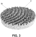
- Figure 3 shows an example of a lens 2 designed by means of a method according to the invention.
- This lens 2 comprises a plurality of fragments 21 which are responsible for making the necessary corrections in the ultrasound beam to establish the desired pattern, centered on the previously defined treatment area.
- Each of these fragments 21 corresponds to a column of the previously described model, the base of each column has the size of one pixel and the height of each column corresponds with the previously indicated Fabry-Perot resonator.
- Figures 4a to 4c show three possible shapes of the beam generated by the emitter and lens assembly according to the invention.
- Figure 4a shows a first option in which the beam is concentrated at two points
- Figure 4b shows a second option in which the beam extends along a curved line
- Figure 4c shows a third option in which the beam covers a previously chosen clearly three-dimensional volume.
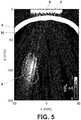
- Figure 5 shows experimental results of a particular embodiment of a method according to the invention.
- the density of ultrasound energy is very high in an area virtually coinciding with the treatment area 4 and is very low in the rest of the cranial cavity 31.
- the lightest color indicates a higher ultrasound pressure, and this level is considerably higher inside the treatment area 4.
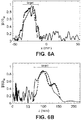
- Figures 6a and 6b show the graphs confirming this fact.
- Figure 6a shows the graph of the amplitude of the pressure waves along the x axis
- Figure 6b shows the graph of the amplitude of the pressure waves along the z axis.
- the results of the computer simulation are represented with a continuous line
- the experimental results are represented with a dotted line. It can be observed how the pressure measured in the experimental step notably fits with what has previously been stated about numerical simulation.
- the dimensions of the treatment area 4 on both axes are marked by means of a segment with the "target" label.
- On both axes x, z it can be observed how the intensity of the pressure waves inside said area is much higher than the intensity outside of said area.
- a piezoelectric material is used for producing the lens object of the invention. This allows obtaining a lens the geometry of which is sensitive to the application of a different electrical voltage to each pixel, therefore the geometry thereof may vary, within limits, once constructed, and even during the working thereof.
Landscapes
- Health & Medical Sciences (AREA)
- Engineering & Computer Science (AREA)
- Physics & Mathematics (AREA)
- Life Sciences & Earth Sciences (AREA)
- General Health & Medical Sciences (AREA)
- Acoustics & Sound (AREA)
- Veterinary Medicine (AREA)
- Radiology & Medical Imaging (AREA)
- Nuclear Medicine, Radiotherapy & Molecular Imaging (AREA)
- Animal Behavior & Ethology (AREA)
- Biomedical Technology (AREA)
- Public Health (AREA)
- Chemical & Material Sciences (AREA)
- Analytical Chemistry (AREA)
- Biochemistry (AREA)
- General Physics & Mathematics (AREA)
- Immunology (AREA)
- Pathology (AREA)
- Ophthalmology & Optometry (AREA)
- Manufacturing & Machinery (AREA)
- Mechanical Engineering (AREA)
- Multimedia (AREA)
- Surgical Instruments (AREA)
- Ultra Sonic Daignosis Equipment (AREA)
Abstract
Description
- This invention pertains to the technical field of apparatus used for the interaction with the brain or the treatment of brain diseases, and of methods for obtaining said apparatus.
- The application of ultrasound through the cranial wall in certain parts of the brain has proven to be useful for performing some treatments, such as ablation of part of the thalamus for the treatment of the essential tremor, for opening the blood-brain barrier and allowing the deposition of medicinal products in a reversible and localized manner, or for neurological stimulation.
- One of the drawbacks of these techniques can be seen when trying to precisely determine the exact location in the brain where ultrasound energy is going to be deposited. This is due to intense reflection, refraction, and absorption the ultrasound wave sustains as it hits the cranial wall, which presents not only an acoustic impedance that is much higher than that of water and soft tissues, but is furthermore a very heterogeneous medium. This problem has conventionally been resolved by means of using a multi-element ultrasound emitter, but it is a very expensive and complex method.
-
US patent document 2016/038770 A1 discloses an apparatus and a method for applying high-intensity focused ultrasound (HIFU) in regions close to the cortex area of the brain with a single-element transducer emitter. - Maimbrough et at. (Maimbourg, G., Houdouin, A., Deffieux, T., Tanter, M., & Aubry, J. F. (2018). 3D-printed adaptive acoustic lens as a disruptive technology for transcranial ultrasound therapy using single-element transducers. Physics in Medicine & Biology, 63(2), 025026) discloses the use of passive plastic lenses for configuring the wave front generated by a single-element emitter such that at the output of the lens, the wave front already incorporates the phase that would be desirable to be corrected for purposes of refraction, reflection, and absorption introduced by the cranial wall. Lenses of this type facilitate the introduction of ultrasound energy into the brain and correct aberrations of the cranial wall. It is a more cost-effective system than the system based on the use of a multi-element emitter, however it is not efficient when trying to treat volumes that are greater than the volume of said focus.
- Ferri et al. (Ferri, M., Bravo, J. M., Redondo, J., & Sanchez-Perez, J. V. (2018). Enhanced 3D-printed holographic acoustic lens for aberration correction of single-element transcranial focused ultrasound. arXiv preprint arXiv: 1805.10007) discloses the use of acoustic lenses obtained by means of 3D-printing to improve the transcranial application of focused ultrasound. The study is centered on improving the numerical simulation providing the changes needed to overcome the absorption phenomena caused by the surface of the cranium. However, it does not represent a substantial improvement with respect to the previous method.
- The present invention provides an improvement with respect to these methods, since it allows optimizing current methods and would even allow extending the scope of application.
- This problem is solved by means of a method for producing a lens for an ultrasound apparatus according to
claim 1 and an ultrasound apparatus according to claim 15. The dependent claims define preferred embodiments of the invention. - Thus, in a first inventive aspect, the invention proposes a method for producing a lens for an ultrasound apparatus, the method comprising the steps of
- providing a bone tissue model, a soft tissue model surrounded by the bone tissue, and a coupling medium model;
- choosing a source point situated inside the coupling medium model;
- choosing a predetermined wave frequency and wavelength, the predetermined frequency being comprised between 100 kHz and 20 MHz and the predetermined wavelength being determined by the predetermined frequency and a velocity of propagation of the wave in the coupling medium model;
- providing a treatment volume situated inside the bone tissue model;
- providing a plurality of nodes distributed inside the treatment volume;
- simulating the emission of a spherical wave from each of the nodes of the plurality of nodes, creating a simulated wave front resulting from the superposition of the spherical waves, each spherical wave requiring an amplitude and a phase, there being at least two nodes with different amplitudes and/or phases, each spherical wave having the predetermined frequency;
- receiving the simulated wave front on a receiving surface which contains the source point;
- processing the results received on the receiving surface;
- on the basis of the processed results, designing a holographic lens surface which can generate a wave pattern equivalent to the simulated, time-reversed, wave front when it receives a wave from a planar, single-element emitter situated at the source point with the predetermined wave frequency and wavelength.
- By means of this method, it is possible to design a passive lens which, when a wave emitted by a single-element ultrasound emitter goes through it, reproduces a three-dimensional acoustic hologram which corresponds with a volume defined by the conditions imposed in the nodes and is as similar as possible to the treatment volume. An ultrasound distribution which is adapted to a specific area of a brain volume to be treated can thus be achieved.
- The plurality of nodes is situated inside the treatment volume. By means of the use of a plurality of nodes distributed inside the treatment volume, an ultrasound beam with three-dimensional variants, such as a curved beam, for example, which has a number of applications in the treatment of brain diseases, can be obtained by using the lens product of the method. Due to the use of the holographic lens product of this production method, some treatments that were carried out with multiple sonications can be achieved by means of a single sonication, using a single-element ultrasound emitter. Due to this simplification in the process and in the materials used, a simpler, more efficient, quicker, and more cost-effective method is obtained.
- The predetermined frequency is chosen before starting the method, primarily due to treatment criteria. Said predetermined frequency is set and will be used for simulating the waves starting from the nodes. On the basis of said frequency and the velocity of the wave in the soft tissue model, the wavelength can be calculated, resulting from dividing the velocity of propagation of the wave in the soft tissue model by the frequency.
- The fact that there are nodes which generate waves with different amplitudes and/or phases allows adjusting these parameters such that a wave front which is more capable of simulating the final result can be obtained.
- In particular embodiments, the plurality of nodes are volumetrically distributed inside the treatment volume.
- A volumetric distribution of the nodes allows obtaining a lens which reproduces a much more complex treatment volume in a sufficiently approximate manner because when the nodes are distributed in a volume, it is possible to provide information which cannot be obtained when the nodes are situated along a curve or on a plane, resulting in a better characterized treatment volume.
- In particular embodiments, the step of processing the results received comprises dividing the receiving surface into pixels and analyzing the amplitude and phase of the wave received in each pixel. In particular embodiments, the pixel size depends on the predetermined wavelength, and in particular the size of each pixel is a square of 5λ/6 of side, A being the predetermined wavelength. Too large of a pixel size would not be suitable for the analysis of wave magnitudes, since all the information received could not be correctly stored. Conversely, too small of a pixel size could cause problems in production, since each pixel corresponds with a column and if the column has a small base, it can produce resonance in reflection modes at the ultrasound working frequency.
- In more particular embodiments, each pixel of the receiving surface is considered as a Fabry-Perot type resonator which can resonate longitudinally, giving rise to a fragment of the lens, and in the step of designing the holographic lens surface equivalent heights are chosen for each fragment of the lens based on the amplitude and phase of the waves received in each pixel of the receiving surface.
- This model is sufficiently precise and suitable for production techniques such as those found today, in which the surface of the lens can be discretized with precision to provide a large number of small pixels working as passive sources, thus being able to create a complex geometry.
- In particular embodiments of the method, the step of designing the lens is performed by means of time reversal.
- The time reversal method is known to one skilled in the art. Basically, this method, which is based on the principles of reciprocity, time invariance, and linearity of the system, consists of emitting a wave from a node and receiving it on a receiving surface, such that on the basis of the data received on the receiving surface, a wave with the original features can be obtained in the node when waves are emitted with the registered phase features on the receiving surface time-inverted.
- As would occur if it had a single node, in the case of the wave front created by several nodes, the receiving surface is divided into pixels. In order to achieve suitable phases of the wave front, each of the pixels is considered as a Fabry-Perot resonator. The height of the equivalent column can be calculated on the basis of the complex transmission coefficient

- Where d is the distance of the lower part of the lens to the receiving surface, Z is the normalized impedance ZL/Z0, ZL is the impedance of the material forming the lens, and Zo is the impedance of water or of the coupling medium between the lens and the cranium. The value of h(x, y) is the height of the equivalent column in the Fabry-Perot resonator. On the basis of this expression and the data associated with each pixel, the equivalent heights in each pixel can be calculated.
- In particular embodiments, any pair of nodes is separated from one another by a distance of less than λ/2, λ being the predetermined wavelength.
- This distribution is sufficient for providing a minimum number of nodes which allows generating data for designing a lens with which a sufficiently precise treatment volume is obtained.
- In particular embodiments of the method, in the step of simulating the emission of spherical waves the amplitude of at least two spherical waves is different. In particular embodiments of the method, an amplitude is imposed on each spherical wave which depends on the distance between the node emitting said spherical wave and the receiving surface.
- The amplitude of a wave is attenuated, among other reasons, due to the distance travelled by said wave, measured with respect to the point of emission. In particular embodiments of the method according to the invention, it is possible for said distance to be different, therefore adjusting the amplitude of the emitted spherical wave to the particular distance from each of the nodes enables obtaining a more reliable result.
- In particular embodiments of the method, the amplitude of each spherical wave is a free parameter, and the method includes the iteration of the steps of simulating the emission of spherical waves, receiving the simulated wave front, and processing the results until obtaining by iteration amplitude values for each spherical wave which give rise to a distribution of sound energy in the treatment volume which exceeds a pre-established target.
- In particular embodiments of the method, in the step of simulating the emission of spherical waves the phase of at least two spherical waves is different. In particular embodiments of the method, a phase is imposed on each spherical wave which depends on the distance between the node emitting said spherical wave and the receiving surface.
- The phase of a wave is affected by the distance travelled by said wave with respect to the point of emission: for one and the same origin, two points situated at different distances result in the wave with a different phase, unless it so happens that the difference between the distances is equal to the wavelength. Adjusting the phase of the spherical wave emitted to the particular distance from each of the nodes enables obtaining a more reliable result.
- In particular embodiments of the method, the phase of each spherical wave is a free parameter, and the method includes the iteration of the steps of simulating the emission of spherical waves, receiving the simulated wave front, and processing the results until obtaining by iteration phase values for each spherical wave which give rise to a distribution of sound energy in the treatment volume which exceeds a pre-established target.
- Another way to solve the design of the lens is to leave the amplitude or phase of each spherical wave as a free parameter and iterate the steps of simulating the emission of spherical waves, receiving the simulated wave front, and processing the results until obtaining by iteration length values of the Fabry-Perot resonator which give rise to a distribution of sound energy in the treatment volume which exceeds a pre-established target. Based on making small modifications in each step of iteration, a more precise result can be obtained.
- In particular embodiments of the method, said method further comprises the step of three-dimensionally printing the design of the lens which has been obtained in the corresponding step.
- Current three-dimensional printing technology allows the production of lenses with tolerances that are sufficiently narrow so that the part produced can respond in a manner sufficiently suitable for being incorporated and used in an ultrasound emission apparatus.
- In particular embodiments, a piezoelectric material is used for producing the lens object of the invention. This allows obtaining a lens the geometry of which is sensitive to the application of a different electrical voltage to each pixel, therefore the geometry thereof may vary, within limits, once constructed, even during the working thereof.
- In a second inventive aspect, the invention provides an apparatus comprising a lens produced by means of a method according to the previous inventive aspect.
- This apparatus presents a lens designed for modifying the ultrasound beam to focus it on a previously chosen volume inside the cranial cavity of a patient. A simpler and more cost-effective apparatus, which furthermore allows medical applications not disclosed up until now, has thereby been obtained.
- This apparatus can be optimal for the low-medium power treatment of structures such as the hippocampus, having a large volume compared with the typical volume of an ultrasound beam, in order to open the blood-brain barrier in a localized region. It can also be optimal for the treatment of regions of the brain for neuronal excitation purposes, producing neurological effects, or for HIFU (high-intensity focalized ultrasound) treatment. This apparatus is also optimal for any application where the ultrasound must go through a barrier to reach the target volume, such as the treatment of internal regions of the knee, through the kneecap, by means of ultrasound. This barrier can be a bone barrier or one consisting of any other material medium providing that the acoustic impedance is different from that of the target volume.
- To complete the description and to better understand the invention, the following set of figures is provided. Said figures are an integral part of the description and illustrate one or more particular examples, which should not be interpreted as restricting the scope of protection of the invention, but rather simple as particular examples of how the invention can be carried out. This set comprises the following figures:
-
Figure 1 shows elements that are part of a treatment method for which an apparatus according to the invention is used. -
Figure 2 shows a diagram of the steps of a particular embodiment of the method according to the invention. -
Figure 3 shows an example of a lens designed by means of a method according to the invention. -
Figures 4a to 4c show three possible shapes of the beam generated by the emitter and lens assembly according to the invention. -
Figure 5 shows experimental results of a particular embodiment of a method according to the invention. -
Figures 6a and 6b show the graphs related to the experimental results. -
Figure 1 describes a general approach to a treatment method for which an apparatus according to the invention is used. - An
ultrasound emitter 1, alens 2, and amodel cranium 3 are observed in this figure. - The
ultrasound emitter 1 consists of a planar or focalized single-element emitter suitable for emitting an ultrasound beam targeting atreatment area 4 situated in acerebral mass 9 inside the cranial cavity enclosed by thecranium 3. Alens 2, which modifies the ultrasound beam emitted by theultrasound emitter 1, in order to adapt it to thetreatment area 4, is interposed between theemitter 1 and thetreatment area 4. The lens is situated inside anaqueous coupling medium 10. In the apparatus and methods known up until now, thetreatment area 4 was reduced to an ellipsoid, which is the typical shape of the focus of a conventional ultrasound beam, and no methods or apparatus that could mold or adapt the focus to complex treatment volumes were known. -
Figure 2 shows a diagram of the steps of a particular embodiment of the method according to the invention, intended for obtaining a lens which allows the modification of the ultrasound beam such that the resulting ultrasound field has a sufficient intensity in a volume which coincides with the treatment area. - A series of
nodes 5 and asource point 6 are observed in this diagram. Thissource point 6 refers to the site where the ultrasound emitter will be centered and thenodes 5 correspond to points representative of the volume intended to be matched with the treatment area. - In this case, the treatment area is intended to be the hippocampus. However, the
nodes 5 are situated in the sagittal plane and are separated from one another by a distance of λ/6, λ being the predetermined wavelength. In turn, thesource point 6 has been situated close to the sagittal plane of the cranium, in order to check the capacity of the lens to turn the ultrasound beam. - Once the
source point 6 and predetermined frequency have been chosen, the following step of the method consists of simulating the emission ofspherical waves 7 at the mentioned frequency from each of thenodes 5, creating a simulated wave front resulting from the superposition of the spherical waves 7. - The amplitude of the spherical waves has been chosen based on the distance between the corresponding node and the receiving
surface 8, and the phase of each spherical wave has also been chosen based on the distance between the corresponding node and the receivingsurface 8. - This simulated wave front is received on the receiving
surface 8 which contains thesource point 6. The wave front received on this receivingsurface 8 is analyzed and in this case, said receiving surface is divided into 1 mm x 1 mm pixels. Once the data of the wave front received in each of the pixels of the receiving surface have been collected and processed, it is possible to design a lens surface, by means of methods such as the calculation of the Fabry-Perot resonator, equivalent heights for each fragment of the lens corresponding to each pixel into which the receiving surface has been divided being chosen, such that a corresponding acoustic hologram can be obtained when said lens is situated in front of a single-element emitter centered on the source point. - When calculating volumetric holograms resulting from the superposition of the waves, pseudo-spectral simulation methods with k-space scatter correction for numerically integrating the linearized constitutive equations of acoustics have been used, as corresponds to cases in which there is a non-homogeneous volume. To resolve this, mesh in which the spatial passage between each of the nodes is λ/6 is precisely chosen.
-
Figure 3 shows an example of alens 2 designed by means of a method according to the invention. - This
lens 2 comprises a plurality offragments 21 which are responsible for making the necessary corrections in the ultrasound beam to establish the desired pattern, centered on the previously defined treatment area. Each of thesefragments 21 corresponds to a column of the previously described model, the base of each column has the size of one pixel and the height of each column corresponds with the previously indicated Fabry-Perot resonator. - Current three-dimensional printing technology allows the production of lenses of this type, in which very tight production tolerances are required so that the lens thus produced can store all the amplitude and phase information necessary for reproducing the ultrasonic holograms and be incorporated in an ultrasound emission apparatus.
-
Figures 4a to 4c show three possible shapes of the beam generated by the emitter and lens assembly according to the invention. -
Figure 4a shows a first option in which the beam is concentrated at two points,Figure 4b shows a second option in which the beam extends along a curved line, andFigure 4c shows a third option in which the beam covers a previously chosen clearly three-dimensional volume. To achieve each of these distributions, the nodes from which the emission of spherical waves will be simulated will be carefully chosen. -
Figure 5 shows experimental results of a particular embodiment of a method according to the invention. - In these results, the
source point 6 in which the emitter is situated, the position of thelens 2, and thetreatment area 4 situated in thecranial cavity 31 enclosed by thecranium 3, can be seen. - As can be observed, the density of ultrasound energy is very high in an area virtually coinciding with the
treatment area 4 and is very low in the rest of thecranial cavity 31. The lightest color indicates a higher ultrasound pressure, and this level is considerably higher inside thetreatment area 4. -
Figures 6a and 6b show the graphs confirming this fact.Figure 6a shows the graph of the amplitude of the pressure waves along the x axis, andFigure 6b shows the graph of the amplitude of the pressure waves along the z axis. In both graphs, the results of the computer simulation are represented with a continuous line, and the experimental results are represented with a dotted line. It can be observed how the pressure measured in the experimental step notably fits with what has previously been stated about numerical simulation. - The dimensions of the
treatment area 4 on both axes are marked by means of a segment with the "target" label. On both axes x, z it can be observed how the intensity of the pressure waves inside said area is much higher than the intensity outside of said area. In particular embodiments, a piezoelectric material is used for producing the lens object of the invention. This allows obtaining a lens the geometry of which is sensitive to the application of a different electrical voltage to each pixel, therefore the geometry thereof may vary, within limits, once constructed, and even during the working thereof.
Claims (17)
- A method for producing a lens (2) for an ultrasound apparatus (1), the method comprising the steps ofproviding a bone tissue model (3), a soft tissue model (9) surrounded by the bone tissue (3), and a coupling medium model (10);choosing a source point (6) situated in the coupling medium model (10);choosing a predetermined wave frequency and wavelength, the predetermined frequency being comprised between 100 kHz and 20 MHz and the predetermined wavelength being determined by the predetermined frequency and a velocity of propagation of the wave in the coupling medium model;providing a treatment volume (4) situated inside the bone tissue model (3);providing a plurality of nodes (5) distributed inside the treatment volume (4);simulating the emission of a spherical wave (7) from each of the nodes (5) of the plurality of nodes, creating a simulated wave front resulting from the superposition of the spherical waves, each spherical wave (7) requiring an amplitude and a phase, there being at least two nodes with different amplitudes and/or phases, each spherical wave having the predetermined frequency;receiving the simulated wave front on a receiving surface (8) which contains the source point (6);processing the results received on the receiving surface (8);on the basis of the processed results, designing a holographic lens surface which can generate a wave pattern equivalent to the simulated, time-reversed, wave front when it receives a wave from a planar, single-element emitter situated at the source point with the predetermined wave frequency and wavelengths.
- The method according to claim 1, wherein the plurality of nodes (5) are volumetrically distributed inside the treatment volume (4).
- The method according to any of the preceding claims, wherein the step of processing the results received comprises dividing the receiving surface into pixels and analyzing the amplitude and phase of the wave received in each pixel.
- The method according to claim 3, wherein the pixel size depends on the predetermined wavelength, and in particular the size of each pixel is a square with 5λ/6 of side, λ being the predetermined wavelength.
- The method according to any of claims 3 to 4, wherein each pixel of the receiving surface is considered as a Fabry-Perot type resonator which can resonate longitudinally, giving rise to a fragment (21) of the lens (2), and in the step of designing the holographic lens surface equivalent heights are chosen for each fragment (21) of the lens (2) based on the amplitude and phase of the wave received in each pixel of the receiving surface.
- The method according to claim 5, wherein the amplitude or the phase of each spherical wave is a free parameter, and the method includes the iteration of the steps of simulating the emission of spherical waves, receiving the simulated wave front, and processing the results until obtaining by iteration length values of the Fabry-Perot resonator which give rise to a distribution of sound energy in the treatment volume which exceeds a pre-established target.
- The method according to any of the preceding claims, wherein in the step of designing the lens (2) a time reversal type method is used.
- The method according to any of the preceding claims, wherein any pair of nodes (5) is separated from one another by a distance of less than λ/2, λ being the predetermined wavelength.
- The method according to any of the preceding claims, wherein in the step of simulating the emission of spherical waves (7) the amplitude of at least two spherical waves is different.
- The method according to claim 9, wherein an amplitude is imposed on each spherical wave (7) which depends on the distance between the node emitting said spherical wave and the receiving surface (8).
- The method according to any of claims 9 or 10, wherein the amplitude of each spherical wave is a free parameter, and the method includes the iteration of the steps of simulating the emission of spherical waves, receiving the simulated wave front, and processing the results until obtaining by iteration amplitude values for each spherical wave which give rise to a distribution of sound energy in the treatment volume which exceeds a pre-established target.
- The method according to any of the preceding claims, wherein in the step of simulating the emission of spherical waves (7) the phase of at least two spherical waves is different.
- The method according to claim 12, wherein a phase is imposed on each spherical wave (7) which depends on the distance between the node (5) emitting said spherical wave and the receiving surface (8).
- The method according to any of claims 12 or 13, wherein the phase of each spherical wave is a free parameter, and the method includes the iteration of the steps of simulating the emission of spherical waves, receiving the simulated wave front, and processing the results until obtaining by iteration phase values for each spherical wave which give rise to a distribution of sound energy in the treatment volume which exceeds a pre-established target.
- The method according to any of the preceding claims, further comprising the step of three-dimensionally printing the design of the lens (2) obtained in the corresponding step.
- The method according to claim 15, wherein a piezoelectric material is used in the step of printing the lens.
- An apparatus (1) comprising a lens (2) produced by means of a method according to the preceding claims.
Applications Claiming Priority (2)
| Application Number | Priority Date | Filing Date | Title |
|---|---|---|---|
| ES201831022A ES2755516B2 (en) | 2018-10-22 | 2018-10-22 | METHOD OF MANUFACTURING A LENS AND ULTRASOUND DEVICE INCLUDING SUCH LENS |
| PCT/ES2019/070713 WO2020084181A1 (en) | 2018-10-22 | 2019-10-21 | Method for producing a lens and ultrasound device comprising the lens |
Publications (4)
| Publication Number | Publication Date |
|---|---|
| EP3871737A1 true EP3871737A1 (en) | 2021-09-01 |
| EP3871737A4 EP3871737A4 (en) | 2022-05-11 |
| EP3871737B1 EP3871737B1 (en) | 2024-01-24 |
| EP3871737C0 EP3871737C0 (en) | 2024-01-24 |
Family
ID=70286661
Family Applications (1)
| Application Number | Title | Priority Date | Filing Date |
|---|---|---|---|
| EP19876539.8A Active EP3871737B1 (en) | 2018-10-22 | 2019-10-21 | Method for producing an acoustic lens |
Country Status (11)
| Country | Link |
|---|---|
| US (1) | US12072316B2 (en) |
| EP (1) | EP3871737B1 (en) |
| JP (1) | JP7438511B2 (en) |
| CN (1) | CN113195052B (en) |
| AU (1) | AU2019369173B2 (en) |
| BR (1) | BR112021007511A2 (en) |
| CL (1) | CL2021000992A1 (en) |
| CO (1) | CO2021006032A2 (en) |
| ES (1) | ES2755516B2 (en) |
| MX (1) | MX2021003836A (en) |
| WO (1) | WO2020084181A1 (en) |
Families Citing this family (5)
| Publication number | Priority date | Publication date | Assignee | Title |
|---|---|---|---|---|
| US12285636B2 (en) | 2021-08-05 | 2025-04-29 | The University Of Washington | Non-planar holographic beam shaping lenses for acoustics |
| US20250135237A1 (en) * | 2021-08-09 | 2025-05-01 | Oxford University Innovation Limited | Ultrasound bean shaping |
| CN116266484A (en) * | 2021-12-18 | 2023-06-20 | 中国科学院深圳先进技术研究院 | Holographic ultrasound transcranial and neural loop regulation system and its design method |
| CN114733092A (en) * | 2022-03-09 | 2022-07-12 | 深圳先进技术研究院 | Transcranial multipoint ultrasonic focusing acoustic holographic lens |
| CN119421779A (en) * | 2022-06-23 | 2025-02-11 | 华盛顿大学 | Bonding of structures using high-intensity focused ultrasound (HIFU) |
Family Cites Families (18)
| Publication number | Priority date | Publication date | Assignee | Title |
|---|---|---|---|---|
| CA1111543A (en) * | 1975-12-01 | 1981-10-27 | Christoph B. Burckhardt | Ultrasonic imaging unit |
| US4633715A (en) * | 1985-05-08 | 1987-01-06 | Canadian Patents And Development Limited - Societe Canadienne Des Brevets Et D'exploitation Limitee | Laser heterodyne interferometric method and system for measuring ultrasonic displacements |
| JPS62277971A (en) * | 1986-05-27 | 1987-12-02 | 創造科学技術研究所有限会社 | Physical remedy apparatus utilizing holography technique |
| JPH0762671B2 (en) * | 1986-06-06 | 1995-07-05 | オリンパス光学工業株式会社 | Acoustic lens |
| JPH06273399A (en) * | 1993-03-18 | 1994-09-30 | Olympus Optical Co Ltd | Acoustic lens |
| JP2002044773A (en) * | 2000-07-28 | 2002-02-08 | Sonix Kk | Acoustic lens and ultrasonic transmitter |
| AU2002254329A1 (en) * | 2001-03-20 | 2002-10-03 | Cornell Research Foundation, Inc. | Precision ultrasound measurement for intraocular lens placement |
| JP2005203976A (en) * | 2004-01-14 | 2005-07-28 | Casio Electronics Co Ltd | Ultrasonic linear array transducer |
| US8102734B2 (en) * | 2007-02-08 | 2012-01-24 | St. Jude Medical, Atrial Fibrillation Division, Inc. | High intensity focused ultrasound transducer with acoustic lens |
| WO2010095094A1 (en) * | 2009-02-20 | 2010-08-26 | Koninklijke Philips Electronics N.V. | Ultrasonic imaging with a variable refractive lens |
| ITPI20110054A1 (en) * | 2011-05-16 | 2012-11-17 | Echolight S R L | ULTRASOUND APPARATUS TO ASSESS THE STATE OF THE BONE STRUCTURE OF A PATIENT |
| CN103370010A (en) * | 2011-10-24 | 2013-10-23 | 松下电器产业株式会社 | photoacoustic camera device |
| US20130172659A1 (en) * | 2011-12-31 | 2013-07-04 | Oron Zachar | Electromagnetic Deep Tissue Excitation |
| WO2013108152A1 (en) * | 2012-01-16 | 2013-07-25 | Ramot At Tel-Aviv University Ltd | Bypassing obstacles in focused acoustic waves |
| US20160038770A1 (en) | 2013-04-26 | 2016-02-11 | Thync, Inc. | Focused transcranial ultrasound systems and methods for using them |
| FR3038217B1 (en) * | 2015-07-01 | 2017-07-21 | Centre Nat De La Rech Scient - Cnrs - | INSONIFICATION METHOD FOR OBTAINING A PREDETERMINED FIELD OF ULTRASONIC WAVES, AND MANUFACTURING METHOD FOR PRODUCING ULTRASONIC LENS FOR THESE PURPOSES |
| EP3179313B1 (en) * | 2015-12-11 | 2021-11-10 | Max-Planck-Gesellschaft zur Förderung der Wissenschaften e.V. | Apparatus and method for creating a holographic ultrasound field in an object |
| CN105536156A (en) * | 2015-12-25 | 2016-05-04 | 中国科学院深圳先进技术研究院 | Ultrasonic brain stimulation or regulation and control method based on large scale area array element and apparatus thereof |
-
2018
- 2018-10-22 ES ES201831022A patent/ES2755516B2/en active Active
-
2019
- 2019-10-21 AU AU2019369173A patent/AU2019369173B2/en active Active
- 2019-10-21 US US17/287,715 patent/US12072316B2/en active Active
- 2019-10-21 EP EP19876539.8A patent/EP3871737B1/en active Active
- 2019-10-21 WO PCT/ES2019/070713 patent/WO2020084181A1/en not_active Ceased
- 2019-10-21 MX MX2021003836A patent/MX2021003836A/en unknown
- 2019-10-21 CN CN201980082758.5A patent/CN113195052B/en active Active
- 2019-10-21 BR BR112021007511-9A patent/BR112021007511A2/en unknown
- 2019-10-21 JP JP2021546480A patent/JP7438511B2/en active Active
-
2021
- 2021-04-20 CL CL2021000992A patent/CL2021000992A1/en unknown
- 2021-05-10 CO CONC2021/0006032A patent/CO2021006032A2/en unknown
Also Published As
| Publication number | Publication date |
|---|---|
| JP7438511B2 (en) | 2024-02-27 |
| WO2020084181A1 (en) | 2020-04-30 |
| EP3871737B1 (en) | 2024-01-24 |
| JP2022512032A (en) | 2022-02-01 |
| CL2021000992A1 (en) | 2021-11-19 |
| BR112021007511A2 (en) | 2021-07-27 |
| US20210396712A1 (en) | 2021-12-23 |
| CO2021006032A2 (en) | 2021-05-20 |
| ES2755516B2 (en) | 2021-08-30 |
| CN113195052A (en) | 2021-07-30 |
| MX2021003836A (en) | 2021-07-21 |
| CN113195052B (en) | 2023-07-18 |
| EP3871737C0 (en) | 2024-01-24 |
| EP3871737A4 (en) | 2022-05-11 |
| AU2019369173B2 (en) | 2024-10-10 |
| ES2755516A1 (en) | 2020-04-22 |
| US12072316B2 (en) | 2024-08-27 |
| CA3116299A1 (en) | 2020-04-30 |
| AU2019369173A1 (en) | 2021-05-20 |
Similar Documents
| Publication | Publication Date | Title |
|---|---|---|
| US12072316B2 (en) | Method for producing a lens and ultrasound device comprising the lens | |
| Rosnitskiy et al. | Design of HIFU transducers for generating specified nonlinear ultrasound fields | |
| CN110191740B (en) | System and method for performing transcranial ultrasound therapy and imaging procedures | |
| Kreider et al. | Characterization of a multi-element clinical HIFU system using acoustic holography and nonlinear modeling | |
| RU2662902C1 (en) | Method and device for creation of high-intensity focused ultrasound fields for noninvasive local destruction of biological tissue | |
| Karzova et al. | Dual-use transducer for ultrasound imaging and pulsed focused ultrasound therapy | |
| Naftchi-Ardebili et al. | Focal volume, acoustic radiation force, and strain in two-transducer regimes | |
| CN114733092A (en) | Transcranial multipoint ultrasonic focusing acoustic holographic lens | |
| KR20240109185A (en) | Helmet and therapeutic ultrasound transducer combination device for opening blood brain barrier and control method for ultrasound of helmet and therapeutic ultrasound transducer combination processing device | |
| CA3116299C (en) | Method for producing a lens and ultrasound device comprising the lens | |
| Xue et al. | Optimization of a random linear ultrasonic therapeutic array based on a genetic algorithm | |
| Baniasad et al. | Transcranial focused ultrasound modulates electrical behavior of the neurons: Design and implementation of a model | |
| KR20230093921A (en) | Ultrasonic transducer positioning apparatus, ultrasonic transducer positioning program and ultrasonic transducer positioning AI implementation method | |
| Rosnitskiy et al. | On the possibility of using multi-element phased arrays for shock-wave action on deep brain structures | |
| Salehnia et al. | Assessment of a Linear Phased Array Transducer Parameters for Brain Stimulation | |
| US20260041395A1 (en) | Method and apparatus for focused ultrasound pressure field based on mri image, and learning method for focused ultrasound pressure field | |
| Zhang et al. | Research on the modulation method of transcranial focused ultrasound based on multi-array transducer | |
| Khan et al. | Integrating data mining with transcranial focused ultrasound to refine neuralgia treatment strategies | |
| Sarvazyan et al. | Time-reversal acoustic focusing system as a virtual random phased array | |
| US20250135237A1 (en) | Ultrasound bean shaping | |
| Ferri et al. | Enhanced 3D-printed holographic acoustic lens for aberration correction of single-element transcranial focused ultrasound | |
| Flatscher | A systematical numerical study on transcranial extracorporeal shock wave therapy (ESWT) | |
| US20250099118A1 (en) | Device and system for the treatment of alzheimer's disease | |
| Karzova et al. | Nonlinear effects in ultrasound fields of diagnostic-type transducers used for kidney stone propulsion: Characterization in water | |
| Sabeddu | Sources of Variability for Acoustic and Thermal Impacts of Transcranial Ultrasonic Neuromodulation in Humans |
Legal Events
| Date | Code | Title | Description |
|---|---|---|---|
| STAA | Information on the status of an ep patent application or granted ep patent |
Free format text: STATUS: THE INTERNATIONAL PUBLICATION HAS BEEN MADE |
|
| TPAC | Observations filed by third parties |
Free format text: ORIGINAL CODE: EPIDOSNTIPA |
|
| PUAI | Public reference made under article 153(3) epc to a published international application that has entered the european phase |
Free format text: ORIGINAL CODE: 0009012 |
|
| STAA | Information on the status of an ep patent application or granted ep patent |
Free format text: STATUS: REQUEST FOR EXAMINATION WAS MADE |
|
| 17P | Request for examination filed |
Effective date: 20210427 |
|
| AK | Designated contracting states |
Kind code of ref document: A1 Designated state(s): AL AT BE BG CH CY CZ DE DK EE ES FI FR GB GR HR HU IE IS IT LI LT LU LV MC MK MT NL NO PL PT RO RS SE SI SK SM TR |
|
| DAV | Request for validation of the european patent (deleted) | ||
| DAX | Request for extension of the european patent (deleted) | ||
| RIC1 | Information provided on ipc code assigned before grant |
Ipc: G03H 3/00 20060101ALI20220114BHEP Ipc: A61N 7/00 20060101ALI20220114BHEP Ipc: A61N 7/02 20060101AFI20220114BHEP |
|
| A4 | Supplementary search report drawn up and despatched |
Effective date: 20220127 |
|
| RIC1 | Information provided on ipc code assigned before grant |
Ipc: G03H 3/00 20060101ALI20220121BHEP Ipc: A61N 7/00 20060101ALI20220121BHEP Ipc: A61N 7/02 20060101AFI20220121BHEP |
|
| DA4 | Supplementary search report drawn up and despatched (deleted) | ||
| RA4 | Supplementary search report drawn up and despatched (corrected) |
Effective date: 20220127 |
|
| RIC1 | Information provided on ipc code assigned before grant |
Ipc: G03H 3/00 20060101ALI20220404BHEP Ipc: A61N 7/00 20060101ALI20220404BHEP Ipc: A61N 7/02 20060101AFI20220404BHEP |
|
| GRAP | Despatch of communication of intention to grant a patent |
Free format text: ORIGINAL CODE: EPIDOSNIGR1 |
|
| STAA | Information on the status of an ep patent application or granted ep patent |
Free format text: STATUS: GRANT OF PATENT IS INTENDED |
|
| INTG | Intention to grant announced |
Effective date: 20230823 |
|
| GRAS | Grant fee paid |
Free format text: ORIGINAL CODE: EPIDOSNIGR3 |
|
| GRAA | (expected) grant |
Free format text: ORIGINAL CODE: 0009210 |
|
| STAA | Information on the status of an ep patent application or granted ep patent |
Free format text: STATUS: THE PATENT HAS BEEN GRANTED |
|
| AK | Designated contracting states |
Kind code of ref document: B1 Designated state(s): AL AT BE BG CH CY CZ DE DK EE ES FI FR GB GR HR HU IE IS IT LI LT LU LV MC MK MT NL NO PL PT RO RS SE SI SK SM TR |
|
| REG | Reference to a national code |
Ref country code: GB Ref legal event code: FG4D |
|
| REG | Reference to a national code |
Ref country code: CH Ref legal event code: EP |
|
| REG | Reference to a national code |
Ref country code: IE Ref legal event code: FG4D |
|
| REG | Reference to a national code |
Ref country code: DE Ref legal event code: R096 Ref document number: 602019045805 Country of ref document: DE |
|
| U01 | Request for unitary effect filed |
Effective date: 20240221 |
|
| U07 | Unitary effect registered |
Designated state(s): AT BE BG DE DK EE FI FR IT LT LU LV MT NL PT SE SI Effective date: 20240229 |
|
| REG | Reference to a national code |
Ref country code: LT Ref legal event code: MG9D |
|
| PG25 | Lapsed in a contracting state [announced via postgrant information from national office to epo] |
Ref country code: IS Free format text: LAPSE BECAUSE OF FAILURE TO SUBMIT A TRANSLATION OF THE DESCRIPTION OR TO PAY THE FEE WITHIN THE PRESCRIBED TIME-LIMIT Effective date: 20240524 |
|
| PG25 | Lapsed in a contracting state [announced via postgrant information from national office to epo] |
Ref country code: GR Free format text: LAPSE BECAUSE OF FAILURE TO SUBMIT A TRANSLATION OF THE DESCRIPTION OR TO PAY THE FEE WITHIN THE PRESCRIBED TIME-LIMIT Effective date: 20240425 |
|
| PG25 | Lapsed in a contracting state [announced via postgrant information from national office to epo] |
Ref country code: HR Free format text: LAPSE BECAUSE OF FAILURE TO SUBMIT A TRANSLATION OF THE DESCRIPTION OR TO PAY THE FEE WITHIN THE PRESCRIBED TIME-LIMIT Effective date: 20240124 Ref country code: RS Free format text: LAPSE BECAUSE OF FAILURE TO SUBMIT A TRANSLATION OF THE DESCRIPTION OR TO PAY THE FEE WITHIN THE PRESCRIBED TIME-LIMIT Effective date: 20240424 |
|
| PG25 | Lapsed in a contracting state [announced via postgrant information from national office to epo] |
Ref country code: ES Free format text: LAPSE BECAUSE OF FAILURE TO SUBMIT A TRANSLATION OF THE DESCRIPTION OR TO PAY THE FEE WITHIN THE PRESCRIBED TIME-LIMIT Effective date: 20240124 |
|
| PG25 | Lapsed in a contracting state [announced via postgrant information from national office to epo] |
Ref country code: RS Free format text: LAPSE BECAUSE OF FAILURE TO SUBMIT A TRANSLATION OF THE DESCRIPTION OR TO PAY THE FEE WITHIN THE PRESCRIBED TIME-LIMIT Effective date: 20240424 Ref country code: NO Free format text: LAPSE BECAUSE OF FAILURE TO SUBMIT A TRANSLATION OF THE DESCRIPTION OR TO PAY THE FEE WITHIN THE PRESCRIBED TIME-LIMIT Effective date: 20240424 Ref country code: IS Free format text: LAPSE BECAUSE OF FAILURE TO SUBMIT A TRANSLATION OF THE DESCRIPTION OR TO PAY THE FEE WITHIN THE PRESCRIBED TIME-LIMIT Effective date: 20240524 Ref country code: HR Free format text: LAPSE BECAUSE OF FAILURE TO SUBMIT A TRANSLATION OF THE DESCRIPTION OR TO PAY THE FEE WITHIN THE PRESCRIBED TIME-LIMIT Effective date: 20240124 Ref country code: GR Free format text: LAPSE BECAUSE OF FAILURE TO SUBMIT A TRANSLATION OF THE DESCRIPTION OR TO PAY THE FEE WITHIN THE PRESCRIBED TIME-LIMIT Effective date: 20240425 Ref country code: ES Free format text: LAPSE BECAUSE OF FAILURE TO SUBMIT A TRANSLATION OF THE DESCRIPTION OR TO PAY THE FEE WITHIN THE PRESCRIBED TIME-LIMIT Effective date: 20240124 |
|
| PG25 | Lapsed in a contracting state [announced via postgrant information from national office to epo] |
Ref country code: PL Free format text: LAPSE BECAUSE OF FAILURE TO SUBMIT A TRANSLATION OF THE DESCRIPTION OR TO PAY THE FEE WITHIN THE PRESCRIBED TIME-LIMIT Effective date: 20240124 |
|
| PG25 | Lapsed in a contracting state [announced via postgrant information from national office to epo] |
Ref country code: PL Free format text: LAPSE BECAUSE OF FAILURE TO SUBMIT A TRANSLATION OF THE DESCRIPTION OR TO PAY THE FEE WITHIN THE PRESCRIBED TIME-LIMIT Effective date: 20240124 |
|
| PG25 | Lapsed in a contracting state [announced via postgrant information from national office to epo] |
Ref country code: SM Free format text: LAPSE BECAUSE OF FAILURE TO SUBMIT A TRANSLATION OF THE DESCRIPTION OR TO PAY THE FEE WITHIN THE PRESCRIBED TIME-LIMIT Effective date: 20240124 |
|
| PG25 | Lapsed in a contracting state [announced via postgrant information from national office to epo] |
Ref country code: CZ Free format text: LAPSE BECAUSE OF FAILURE TO SUBMIT A TRANSLATION OF THE DESCRIPTION OR TO PAY THE FEE WITHIN THE PRESCRIBED TIME-LIMIT Effective date: 20240124 |
|
| REG | Reference to a national code |
Ref country code: DE Ref legal event code: R097 Ref document number: 602019045805 Country of ref document: DE |
|
| PG25 | Lapsed in a contracting state [announced via postgrant information from national office to epo] |
Ref country code: SK Free format text: LAPSE BECAUSE OF FAILURE TO SUBMIT A TRANSLATION OF THE DESCRIPTION OR TO PAY THE FEE WITHIN THE PRESCRIBED TIME-LIMIT Effective date: 20240124 |
|
| PG25 | Lapsed in a contracting state [announced via postgrant information from national office to epo] |
Ref country code: SM Free format text: LAPSE BECAUSE OF FAILURE TO SUBMIT A TRANSLATION OF THE DESCRIPTION OR TO PAY THE FEE WITHIN THE PRESCRIBED TIME-LIMIT Effective date: 20240124 Ref country code: SK Free format text: LAPSE BECAUSE OF FAILURE TO SUBMIT A TRANSLATION OF THE DESCRIPTION OR TO PAY THE FEE WITHIN THE PRESCRIBED TIME-LIMIT Effective date: 20240124 Ref country code: CZ Free format text: LAPSE BECAUSE OF FAILURE TO SUBMIT A TRANSLATION OF THE DESCRIPTION OR TO PAY THE FEE WITHIN THE PRESCRIBED TIME-LIMIT Effective date: 20240124 |
|
| U20 | Renewal fee for the european patent with unitary effect paid |
Year of fee payment: 6 Effective date: 20241014 |
|
| U1N | Appointed representative for the unitary patent procedure changed after the registration of the unitary effect |
Representative=s name: TRBL INTELLECTUAL PROPERTY; ES |
|
| PLBE | No opposition filed within time limit |
Free format text: ORIGINAL CODE: 0009261 |
|
| STAA | Information on the status of an ep patent application or granted ep patent |
Free format text: STATUS: NO OPPOSITION FILED WITHIN TIME LIMIT |
|
| 26N | No opposition filed |
Effective date: 20241025 |
|
| PG25 | Lapsed in a contracting state [announced via postgrant information from national office to epo] |
Ref country code: MC Free format text: LAPSE BECAUSE OF FAILURE TO SUBMIT A TRANSLATION OF THE DESCRIPTION OR TO PAY THE FEE WITHIN THE PRESCRIBED TIME-LIMIT Effective date: 20240124 |
|
| U20 | Renewal fee for the european patent with unitary effect paid |
Year of fee payment: 7 Effective date: 20250805 |
|
| PG25 | Lapsed in a contracting state [announced via postgrant information from national office to epo] |
Ref country code: IE Free format text: LAPSE BECAUSE OF NON-PAYMENT OF DUE FEES Effective date: 20241021 |
|
| REG | Reference to a national code |
Ref country code: CH Ref legal event code: U11 Free format text: ST27 STATUS EVENT CODE: U-0-0-U10-U11 (AS PROVIDED BY THE NATIONAL OFFICE) Effective date: 20251101 |
|
| PG25 | Lapsed in a contracting state [announced via postgrant information from national office to epo] |
Ref country code: RO Free format text: LAPSE BECAUSE OF FAILURE TO SUBMIT A TRANSLATION OF THE DESCRIPTION OR TO PAY THE FEE WITHIN THE PRESCRIBED TIME-LIMIT Effective date: 20240124 |
|
| PGFP | Annual fee paid to national office [announced via postgrant information from national office to epo] |
Ref country code: GB Payment date: 20251027 Year of fee payment: 7 |
|
| PGFP | Annual fee paid to national office [announced via postgrant information from national office to epo] |
Ref country code: CH Payment date: 20251101 Year of fee payment: 7 |
|
| PG25 | Lapsed in a contracting state [announced via postgrant information from national office to epo] |
Ref country code: CY Free format text: LAPSE BECAUSE OF FAILURE TO SUBMIT A TRANSLATION OF THE DESCRIPTION OR TO PAY THE FEE WITHIN THE PRESCRIBED TIME-LIMIT; INVALID AB INITIO Effective date: 20191021 |
|
| PG25 | Lapsed in a contracting state [announced via postgrant information from national office to epo] |
Ref country code: HU Free format text: LAPSE BECAUSE OF FAILURE TO SUBMIT A TRANSLATION OF THE DESCRIPTION OR TO PAY THE FEE WITHIN THE PRESCRIBED TIME-LIMIT; INVALID AB INITIO Effective date: 20191021 |