EP3871636A1 - Method for testing additively manufactured orthopaedic prosthetic components - Google Patents
Method for testing additively manufactured orthopaedic prosthetic components Download PDFInfo
- Publication number
- EP3871636A1 EP3871636A1 EP21159521.0A EP21159521A EP3871636A1 EP 3871636 A1 EP3871636 A1 EP 3871636A1 EP 21159521 A EP21159521 A EP 21159521A EP 3871636 A1 EP3871636 A1 EP 3871636A1
- Authority
- EP
- European Patent Office
- Prior art keywords
- particle
- particles
- liquid
- substrate
- orthopaedic
- Prior art date
- Legal status (The legal status is an assumption and is not a legal conclusion. Google has not performed a legal analysis and makes no representation as to the accuracy of the status listed.)
- Granted
Links
Images





Classifications
-
- A—HUMAN NECESSITIES
- A61—MEDICAL OR VETERINARY SCIENCE; HYGIENE
- A61F—FILTERS IMPLANTABLE INTO BLOOD VESSELS; PROSTHESES; DEVICES PROVIDING PATENCY TO, OR PREVENTING COLLAPSING OF, TUBULAR STRUCTURES OF THE BODY, e.g. STENTS; ORTHOPAEDIC, NURSING OR CONTRACEPTIVE DEVICES; FOMENTATION; TREATMENT OR PROTECTION OF EYES OR EARS; BANDAGES, DRESSINGS OR ABSORBENT PADS; FIRST-AID KITS
- A61F2/00—Filters implantable into blood vessels; Prostheses, i.e. artificial substitutes or replacements for parts of the body; Appliances for connecting them with the body; Devices providing patency to, or preventing collapsing of, tubular structures of the body, e.g. stents
- A61F2/02—Prostheses implantable into the body
- A61F2/30—Joints
- A61F2/3094—Designing or manufacturing processes
-
- B—PERFORMING OPERATIONS; TRANSPORTING
- B29—WORKING OF PLASTICS; WORKING OF SUBSTANCES IN A PLASTIC STATE IN GENERAL
- B29C—SHAPING OR JOINING OF PLASTICS; SHAPING OF MATERIAL IN A PLASTIC STATE, NOT OTHERWISE PROVIDED FOR; AFTER-TREATMENT OF THE SHAPED PRODUCTS, e.g. REPAIRING
- B29C71/00—After-treatment of articles without altering their shape; Apparatus therefor
- B29C71/0009—After-treatment of articles without altering their shape; Apparatus therefor using liquids, e.g. solvents, swelling agents
-
- A—HUMAN NECESSITIES
- A61—MEDICAL OR VETERINARY SCIENCE; HYGIENE
- A61F—FILTERS IMPLANTABLE INTO BLOOD VESSELS; PROSTHESES; DEVICES PROVIDING PATENCY TO, OR PREVENTING COLLAPSING OF, TUBULAR STRUCTURES OF THE BODY, e.g. STENTS; ORTHOPAEDIC, NURSING OR CONTRACEPTIVE DEVICES; FOMENTATION; TREATMENT OR PROTECTION OF EYES OR EARS; BANDAGES, DRESSINGS OR ABSORBENT PADS; FIRST-AID KITS
- A61F2/00—Filters implantable into blood vessels; Prostheses, i.e. artificial substitutes or replacements for parts of the body; Appliances for connecting them with the body; Devices providing patency to, or preventing collapsing of, tubular structures of the body, e.g. stents
- A61F2/02—Prostheses implantable into the body
- A61F2/30—Joints
- A61F2/30767—Special external or bone-contacting surface, e.g. coating for improving bone ingrowth
-
- B—PERFORMING OPERATIONS; TRANSPORTING
- B33—ADDITIVE MANUFACTURING TECHNOLOGY
- B33Y—ADDITIVE MANUFACTURING, i.e. MANUFACTURING OF THREE-DIMENSIONAL [3D] OBJECTS BY ADDITIVE DEPOSITION, ADDITIVE AGGLOMERATION OR ADDITIVE LAYERING, e.g. BY 3D PRINTING, STEREOLITHOGRAPHY OR SELECTIVE LASER SINTERING
- B33Y40/00—Auxiliary operations or equipment, e.g. for material handling
- B33Y40/20—Post-treatment, e.g. curing, coating or polishing
-
- A—HUMAN NECESSITIES
- A61—MEDICAL OR VETERINARY SCIENCE; HYGIENE
- A61F—FILTERS IMPLANTABLE INTO BLOOD VESSELS; PROSTHESES; DEVICES PROVIDING PATENCY TO, OR PREVENTING COLLAPSING OF, TUBULAR STRUCTURES OF THE BODY, e.g. STENTS; ORTHOPAEDIC, NURSING OR CONTRACEPTIVE DEVICES; FOMENTATION; TREATMENT OR PROTECTION OF EYES OR EARS; BANDAGES, DRESSINGS OR ABSORBENT PADS; FIRST-AID KITS
- A61F2/00—Filters implantable into blood vessels; Prostheses, i.e. artificial substitutes or replacements for parts of the body; Appliances for connecting them with the body; Devices providing patency to, or preventing collapsing of, tubular structures of the body, e.g. stents
- A61F2/02—Prostheses implantable into the body
- A61F2/30—Joints
- A61F2002/30001—Additional features of subject-matter classified in A61F2/28, A61F2/30 and subgroups thereof
- A61F2002/30003—Material related properties of the prosthesis or of a coating on the prosthesis
- A61F2002/30004—Material related properties of the prosthesis or of a coating on the prosthesis the prosthesis being made from materials having different values of a given property at different locations within the same prosthesis
- A61F2002/30011—Material related properties of the prosthesis or of a coating on the prosthesis the prosthesis being made from materials having different values of a given property at different locations within the same prosthesis differing in porosity
-
- A—HUMAN NECESSITIES
- A61—MEDICAL OR VETERINARY SCIENCE; HYGIENE
- A61F—FILTERS IMPLANTABLE INTO BLOOD VESSELS; PROSTHESES; DEVICES PROVIDING PATENCY TO, OR PREVENTING COLLAPSING OF, TUBULAR STRUCTURES OF THE BODY, e.g. STENTS; ORTHOPAEDIC, NURSING OR CONTRACEPTIVE DEVICES; FOMENTATION; TREATMENT OR PROTECTION OF EYES OR EARS; BANDAGES, DRESSINGS OR ABSORBENT PADS; FIRST-AID KITS
- A61F2/00—Filters implantable into blood vessels; Prostheses, i.e. artificial substitutes or replacements for parts of the body; Appliances for connecting them with the body; Devices providing patency to, or preventing collapsing of, tubular structures of the body, e.g. stents
- A61F2/02—Prostheses implantable into the body
- A61F2/30—Joints
- A61F2002/30001—Additional features of subject-matter classified in A61F2/28, A61F2/30 and subgroups thereof
- A61F2002/30108—Shapes
- A61F2002/30199—Three-dimensional shapes
- A61F2002/3028—Three-dimensional shapes polyhedral different from parallelepipedal and pyramidal
-
- A—HUMAN NECESSITIES
- A61—MEDICAL OR VETERINARY SCIENCE; HYGIENE
- A61F—FILTERS IMPLANTABLE INTO BLOOD VESSELS; PROSTHESES; DEVICES PROVIDING PATENCY TO, OR PREVENTING COLLAPSING OF, TUBULAR STRUCTURES OF THE BODY, e.g. STENTS; ORTHOPAEDIC, NURSING OR CONTRACEPTIVE DEVICES; FOMENTATION; TREATMENT OR PROTECTION OF EYES OR EARS; BANDAGES, DRESSINGS OR ABSORBENT PADS; FIRST-AID KITS
- A61F2/00—Filters implantable into blood vessels; Prostheses, i.e. artificial substitutes or replacements for parts of the body; Appliances for connecting them with the body; Devices providing patency to, or preventing collapsing of, tubular structures of the body, e.g. stents
- A61F2/02—Prostheses implantable into the body
- A61F2/30—Joints
- A61F2002/30001—Additional features of subject-matter classified in A61F2/28, A61F2/30 and subgroups thereof
- A61F2002/30316—The prosthesis having different structural features at different locations within the same prosthesis; Connections between prosthetic parts; Special structural features of bone or joint prostheses not otherwise provided for
- A61F2002/30535—Special structural features of bone or joint prostheses not otherwise provided for
- A61F2002/30593—Special structural features of bone or joint prostheses not otherwise provided for hollow
-
- A—HUMAN NECESSITIES
- A61—MEDICAL OR VETERINARY SCIENCE; HYGIENE
- A61F—FILTERS IMPLANTABLE INTO BLOOD VESSELS; PROSTHESES; DEVICES PROVIDING PATENCY TO, OR PREVENTING COLLAPSING OF, TUBULAR STRUCTURES OF THE BODY, e.g. STENTS; ORTHOPAEDIC, NURSING OR CONTRACEPTIVE DEVICES; FOMENTATION; TREATMENT OR PROTECTION OF EYES OR EARS; BANDAGES, DRESSINGS OR ABSORBENT PADS; FIRST-AID KITS
- A61F2/00—Filters implantable into blood vessels; Prostheses, i.e. artificial substitutes or replacements for parts of the body; Appliances for connecting them with the body; Devices providing patency to, or preventing collapsing of, tubular structures of the body, e.g. stents
- A61F2/02—Prostheses implantable into the body
- A61F2/30—Joints
- A61F2/30767—Special external or bone-contacting surface, e.g. coating for improving bone ingrowth
- A61F2002/30769—Special external or bone-contacting surface, e.g. coating for improving bone ingrowth madreporic
-
- A—HUMAN NECESSITIES
- A61—MEDICAL OR VETERINARY SCIENCE; HYGIENE
- A61F—FILTERS IMPLANTABLE INTO BLOOD VESSELS; PROSTHESES; DEVICES PROVIDING PATENCY TO, OR PREVENTING COLLAPSING OF, TUBULAR STRUCTURES OF THE BODY, e.g. STENTS; ORTHOPAEDIC, NURSING OR CONTRACEPTIVE DEVICES; FOMENTATION; TREATMENT OR PROTECTION OF EYES OR EARS; BANDAGES, DRESSINGS OR ABSORBENT PADS; FIRST-AID KITS
- A61F2/00—Filters implantable into blood vessels; Prostheses, i.e. artificial substitutes or replacements for parts of the body; Appliances for connecting them with the body; Devices providing patency to, or preventing collapsing of, tubular structures of the body, e.g. stents
- A61F2/02—Prostheses implantable into the body
- A61F2/30—Joints
- A61F2/30767—Special external or bone-contacting surface, e.g. coating for improving bone ingrowth
- A61F2002/3092—Special external or bone-contacting surface, e.g. coating for improving bone ingrowth having an open-celled or open-pored structure
-
- A—HUMAN NECESSITIES
- A61—MEDICAL OR VETERINARY SCIENCE; HYGIENE
- A61F—FILTERS IMPLANTABLE INTO BLOOD VESSELS; PROSTHESES; DEVICES PROVIDING PATENCY TO, OR PREVENTING COLLAPSING OF, TUBULAR STRUCTURES OF THE BODY, e.g. STENTS; ORTHOPAEDIC, NURSING OR CONTRACEPTIVE DEVICES; FOMENTATION; TREATMENT OR PROTECTION OF EYES OR EARS; BANDAGES, DRESSINGS OR ABSORBENT PADS; FIRST-AID KITS
- A61F2/00—Filters implantable into blood vessels; Prostheses, i.e. artificial substitutes or replacements for parts of the body; Appliances for connecting them with the body; Devices providing patency to, or preventing collapsing of, tubular structures of the body, e.g. stents
- A61F2/02—Prostheses implantable into the body
- A61F2/30—Joints
- A61F2/3094—Designing or manufacturing processes
- A61F2002/30985—Designing or manufacturing processes using three dimensional printing [3DP]
-
- B—PERFORMING OPERATIONS; TRANSPORTING
- B29—WORKING OF PLASTICS; WORKING OF SUBSTANCES IN A PLASTIC STATE IN GENERAL
- B29C—SHAPING OR JOINING OF PLASTICS; SHAPING OF MATERIAL IN A PLASTIC STATE, NOT OTHERWISE PROVIDED FOR; AFTER-TREATMENT OF THE SHAPED PRODUCTS, e.g. REPAIRING
- B29C71/00—After-treatment of articles without altering their shape; Apparatus therefor
- B29C71/0009—After-treatment of articles without altering their shape; Apparatus therefor using liquids, e.g. solvents, swelling agents
- B29C2071/0027—Removing undesirable residual components, e.g. solvents, unreacted monomers
-
- B—PERFORMING OPERATIONS; TRANSPORTING
- B29—WORKING OF PLASTICS; WORKING OF SUBSTANCES IN A PLASTIC STATE IN GENERAL
- B29L—INDEXING SCHEME ASSOCIATED WITH SUBCLASS B29C, RELATING TO PARTICULAR ARTICLES
- B29L2031/00—Other particular articles
- B29L2031/753—Medical equipment; Accessories therefor
- B29L2031/7532—Artificial members, protheses
Definitions
- the present disclosure relates generally to prosthetic orthopaedic components, and more particularly to such components including an additively manufactured structure.
- the embodiments disclosed herein are generally directed towards three-dimensional porous structures for bone ingrowth and methods for producing said structures.
- Examples of modern rapid prototyping/additive manufacturing techniques include sheet lamination, adhesion bonding, laser sintering (or selective laser sintering), laser melting (or selective laser sintering), photopolymerization, droplet deposition, stereolithography, 3D printing, fused deposition modeling, and 3D plotting. Particularly in the areas of selective laser sintering, selective laser melting and 3D printing, the improvement in the production of high density parts has made those techniques useful in designing and accurately producing articles such as highly dense metal parts.
- the additive manufacturing field has created orthopaedic prosthetic components that promote mammalian cell growth and regeneration.
- Current methods and geometries can control the pore size distribution, which exerts a strong influence on the ingrowth behavior of mammalian cells such as bone, and further produce porous structures having unit cell geometries with pore sizes and porosities simultaneously in the range believed to be beneficial for ingrowth while maintaining structural integrity during the manufacturing process (e.g., 3D printing).
- a method for removing at least one particle from an additively manufactured orthopaedic prosthetic component.
- the method includes the step of submerging at least a portion of the additively manufactured orthopaedic prosthetic component in a liquid.
- the method further includes the step of sonicating at least a portion of the additively manufactured orthopaedic prosthetic component so as to loosen the at least one particle.
- the method further includes the step of shaking the additively manufactured orthopaedic prosthetic component so as to evacuate the at least one particle from the additively manufactured orthopaedic prosthetic component.
- the loosened at least one particle is detached from the orthopaedic prosthetic component but disposed in the orthopaedic prosthetic component.
- the shaking step may be performed while the at least one particle is submerged in the liquid.
- the sonicating step occurs at a sonication frequency
- shaking step occurs at a shaking frequency that is less than the sonication frequency.
- the liquid is polar in one embodiment.
- the liquid is nonpolar or substantially nonpolar.
- the method can include the step of increasing a density of the liquid.
- the method can include the step of adding a salt to the liquid to increase the density.
- the method further includes the step of adding a dispersion agent to the liquid.
- the method includes the step of filtering the at least one particle from the fluid.
- the filtering step causes the liquid to flow through the filtration substrate, and prevents the at least one particle to flow through the filtration substrate during the causing step.
- the weight of the at least one particle is determined.
- a method for evaluating an orthopaedic prosthetic component.
- the method for evaluating the orthopaedic prosthetic component can be performed individually, or in combination with any of the steps associated with the method for removing the at least one particle from the orthopaedic prosthetic component.
- the orthopaedic prosthetic component includes an additively manufactured structure having a at least one residual particle.
- the another embodiment or the embodiment method can include the step of obtaining a magnified image of at least a portion of a substrate and at least one particle supported by the substrate, such as the evacuated at least one particle supported by the substrate. The magnified image may be viewed on a display.
- the at least one particle may be surrounded by at least one boundary line on the image along a respective outer perimeter of the at least one particle.
- the method may further includes the step of determining at least one of 1) a quantity of the at least one particle and/or a quantity of groups of the at least one particle, 2) a size of the at least one particle, 3) an aspect ratio of the at least one particle, and 4) a weight of the at least one particle.
- the method further includes the step of removing the at least one particle from the orthopaedic prosthetic component.
- the method can further include the step of placing the substrate under a microscope so as to generate the magnified image.
- the method further includes the step of thresholding the image so as to define the at least one boundary line, potentially wherein an area defined by the boundary represents at least one particle.
- the at least one particle comprises a plurality of groups of particles spaced from each other in their respective entireties
- the method further includes the step of identifying a region of interest on the substrate that surrounds all of the particles prior to the surrounding step.
- the substrate can comprise a filter paper or any other substrate suitable for supporting the particles.
- the method further includes the step of thresholding the region of interest so as to surround the plurality of particles with respective boundary lines.
- the method includes the step of scanning each at least one particle inside each respective at least one boundary line to determine a characteristic of the at least one particle, the at least one characteristic including at least one of 1) a quantity of the at least one particle and/or the quantity of groups of the at least one particle, 2) a size of the at least one particle, and 3) an aspect ratio of the at least one particle.
- the method can include the step of comparing the determined characteristic against a predetermined threshold.
- the method further includes the step of providing illumination to the region of interest prior to the thresholding step. The illumination of the particles on the substrate can be adjusted to within a predetermined illumination range.
- the method may further comprise the step of placing the substrate under a microscope so as to generate the magnified image.
- the at least one particle may have been evacuated from an orthopaedic prosthetic component or from a plurality of orthopaedic prosthetic components.
- a still further embodiment may provide a method for evaluating an orthopaedic prosthetic component, the method comprising the steps of: obtaining a magnified image of at least a portion of a substrate and at least one particle supported by the substrate, wherein the at least one particle has been removed from the an additively manufactured structure of the orthopaedic prosthetic component; viewing the magnified image on a display; surrounding the at least one particle with at least one boundary line on the image along a respective outer perimeter of the at least one particle, respectively; and determining at least one of 1) a quantity of groups of the at least one particle, 2) a size of the at least one particle, 3) an aspect ratio of the at least one particle, and 4) a weight of the at least one particle.
- the embodiment may further comprise the step of thresholding the image so as to define the at least one boundary line, wherein the boundary line surrounds an area that represents the particle, the method comprising the step of scanning the area so as to determine at least one of 1) a quantity of groups of the at least one particle, 2) the size of the at least one particle, and 3) the aspect ratio of the at least one particle.
- references in the specification to "one embodiment”, “an embodiment”, “an example embodiment”, etc., indicate that the embodiment described may include a particular feature, structure, or characteristic, but every embodiment may not necessarily include the particular feature, structure, or characteristic. Moreover, such phrases are not necessarily referring to the same embodiment. Further, when a particular feature, structure, or characteristic is described in connection with an embodiment, it is submitted that it is within the knowledge of one skilled in the art to effect such feature, structure, or characteristic in connection with other embodiments whether or not explicitly described.
- references in the specification to "about,” “approximately,” “substantially,” derivatives thereof, and words of similar import, when used to describe one or more parameters including sizes, shapes, spatial relationships, distances, directions, and other similar parameters includes the stated parameter in addition to a range up to 10% more and up to 10% less than the stated parameter, including 5% more and 5% less, including 3% more and 3% less, including 1% more and 1% less.
- the present disclosure relates to the additive manufacture of porous three-dimensional metallic structures for orthopaedic prosthetic components, and methods for analyzing the manufacture of such structures.
- the porous metallic structures promote hard or soft tissue interlocks between prosthetic components implanted in a patient's body and the patient's surrounding hard or soft tissue.
- the porous three-dimensional metallic structure can be used to provide a porous outer layer of the orthopaedic prosthetic component to form a bone in-growth structure.
- the porous three-dimensional metallic structure can be used as an implant with the required structural integrity to both fulfill the intended function of the implant and to provide interconnected porosity for tissue interlock (e.g., bone in-growth) with the surrounding tissue.
- tissue interlock e.g., bone in-growth
- the types of metals that can be used to form the porous three-dimensional metallic structures can include, but are not limited to, titanium, titanium alloys, stainless steel, cobalt chrome alloys, tantalum or niobium.
- the prosthetic component 100 includes a base 110, a porous three-dimensional structure or layer 120, and a cone or stem 130 extending away from the base 110.
- the porous structure 120 surrounds a portion of the base 110 and a portion of the stem 130.
- the porous structure 120 may also provide the entire structure of the prosthetic component 100 or as a coating that surrounds some or all of the base 110 and/or all of the stem 130.
- the porous structure includes a plurality of unit cells that define voids or spaces that permit the ingrowth of bone, thereby promoting fixation of the prosthetic component 100 to a patient's bone.
- the orthopaedic implant 100 may be implanted into a tibial bone.
- the stem 130 can be inserted into the tibial bone, with a ledge portion 140 of implant 100 resting against a proximal portion of the tibial bone.
- the various porous structures described herein may be incorporated into various orthopaedic implant designs, including, for example, a tibial prosthetic component or a femoral prosthetic component similar to the tibial and femoral components shown in U.S. Patent No. 8,470,047 , which is expressly incorporated herein by reference.
- the porous structures may also be included in other orthopaedic implant designs, including a patella component shaped to engage a femoral prosthetic component and prosthetic components for use in a hip or shoulder arthroplasty surgery
- the base 110 can be any type of structure capable of, for example, contacting, supporting, connecting to or with, or anchoring to or with components of various embodiments herein.
- the base 110 can include, for example, a metal or non-metal tray, a metal or non-metal baseplate, a metal or non-metal structure that sits on a tray, and so on.
- the types of metal that can be used to form the base 110 include, but are not limited to, titanium, titanium alloys, stainless steel, cobalt chrome alloys, tantalum or niobium.
- the stem 130 includes a solid region 150, which is coated by a porous region 160 of the porous structure 120.
- the solid region 150 of the stem 130 is anchored to the base 110 and extends outwardly from the porous structure 120 such that the porous structure 120 surrounds the region of stem 130 proximal to base 110.
- the stem 130 may be anchored to the porous structure 120.
- the types of metal that can be used to form the stem 130 include, but are not limited to, titanium, titanium alloys, stainless steel, cobalt chrome alloys, tantalum or niobium.
- the porous structure 120 of the implant 100 can comprise a plurality of connected unit cells.
- Each unit cell defines a unit cell structure 200 that includes a plurality of lattice struts 210 so as to define a first geometric structure 230.
- Each unit cell further defines a plurality of internal struts 220 that are disposed within the first geometric structure 230 so as to define a plurality of second geometric structures 240.
- the first geometric structure 230 can include the plurality of lattice struts 210.
- the lattice struts 210 cooperate to define the first geometry.
- Each second geometric structure 240 can be formed by a plurality of the internal struts 220 and a plurality of the lattice struts 210. Each of the plurality of second geometric structures 240 can define an internal volume that is substantially equal to the internal volumes of the other second geometric structures 240.
- the first geometric structure can be a rhombic dodecahedron
- the second geometric structure can be a rhombic trigonal trapezohedron. It should be appreciated, of course, that the first and second geometric structures can vary as desired. Further, it should be appreciated that the unit cells that make up the casing 33 can have any suitable alternative geometry as desired.
- the unit cells can be defined by the plurality of lattice struts 210 without internal struts 220.
- the unit cells can be defined by lattice struts 210 and internal struts 220 that define any suitable geometry, respectively, as desired. Examples of such alternative geometries are described in U.S. Patent Application Serial No. 16/365,557 filed March 26, 2019 , which is expressly incorporated herein by reference.
- the porous three-dimensional structure 120 can be fabricated using any suitable additive manufacturing process as desired, including any of the additive manufacturing processes described below. It is recognized that structures created using additive manufacturing processes can include residual particles as artifacts of the additive printing process. For instance, some additive manufacturing processes involve the deposition of a layer of powder onto a base, and fusing the layer of powder to the base. Subsequent layers of powder are deposited onto the respective preceding layers and subsequently fused to the previous layer to form the porous three-dimensional metallic structures. It is recognized that the manufactured porous three-dimensional structure 120 can include quantities of particles 122 that are to be removed prior to use. For instance, the completed part can include residual particles in the form of powder or other particulates.
- the residual powder can be the product of the additive manufacturing process, and can thus include, but are not limited to, titanium, titanium alloys, stainless steel, cobalt chrome alloys, tantalum or niobium.
- the particles can be soil or other debris that may reside on or in the manufactured structure 120.
- a method 300 is provided for removing the residual particles 122 from the porous three-dimensional structure 120 for subsequent analysis.
- the method 300 can include the first step 302 of cleaning the prosthetic orthopaedic component 100 so as to remove the particles 122 from the component 100.
- the particles 122 can be adhered, bonded, or otherwise attached to the component 100 after the porous three-dimensional structure 120 has been manufactured.
- the particles 122 can be adhered, bonded, or otherwise attached to the base 110 and/or the stem 130.
- the particles 122 can be adhered, bonded, or otherwise attached to the porous three-dimensional structure 120.
- the cleaning step 302 is configured to remove the particles 122 from the component 100.
- a solvent 250 that is disposed in any suitable container 252, such as a beaker or other suitable pourable container.
- the solvent 250 can be any suitable fluid such as a liquid.
- the liquid can be nonpolar.
- the liquid can be water, such as deionized water in some embodiments.
- the liquid can be substantially polar.
- the liquid can be acetone or an alcohol, such as isopropyl alcohol (IPA).
- IPA isopropyl alcohol
- the liquid can be oil based.
- liquids of different viscosities can be provided.
- Liquids having high viscosities can increase the transportability of the particles 122 in the solvent 250.
- the orthopaedic prosthetic component 100 is placed in the container 252 such that at least the porous three-dimensional structure 120 is submerged in the solvent 250. In some embodiments, an entirety of the orthopaedic prosthetic component 100 can be submerged in the solvent 250.
- a densifier can be added to the solvent 250 that increases the density of the solvent.
- the densifier is salt.
- Increasing the density of the solvent 250 increases the buoyancy of the particles 122 and reduces the tendency for the particles 122 to accumulate on the bottom of the container 252.
- increasing the density of the solvent 250 can increase the transportability of the particles 122 in the solvent 250.
- any suitable dispersion agent such as a detergent can be added to the solvent 250 as desired.
- the dispersing agent increases the dispersion of the particles 122 in the solvent 250. Any one or more of these additives can be included in the solvent 250 as desired.
- the single orthopaedic prosthetic component 100 is placed in the container 252.
- a plurality of orthopaedic prosthetic components 100 can be placed in the container 252. This embodiment can be particularly suitable when it is desired to efficiently analyze the particles 122 of a plurality of orthopaedic prosthetic components 100. This embodiment can also be particularly suitable when it is desired to remove, but not analyze, the particles 122 from a plurality of orthopaedic prosthetic components 100.
- the cleaning step 302 includes the step 303 of loosening the attached particles 122 from the prosthetic orthopaedic component 100.
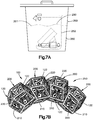
- the porous orthopaedic component 100 is sonicated to loosen the attached particles 122 from the prosthetic orthopaedic component 100.
- a sonicator 350 may be used to subject the component 100 to high frequency vibration
- the sonicator 350 is activated to deliver high frequency vibration to the porous orthopaedic component 100.
- the sonicator 350 can be of the type that includes a sonication tank that contains a sonication liquid 351 configured to deliver the high frequency vibration to the container 252.
- the high frequency vibration is delivered to the container 252 at an ultrasonic frequency.
- the sonication liquid can be water, such as reverse osmosis (RO) water.
- the container 252 is placed in the in the sonicator 350 such that the container 252 is disposed in the sonication liquid 351 at a position that prevents the sonication liquid 351 from entering the container 252 during use.
- the sonicator 350 is activated to deliver high frequency vibration to the container 252 at any suitable sonication frequency for any suitable duration at any suitable temperature.
- the temperature can be any suitable temperature as desired. In one example, the temperature can be between about 40 degrees F to approximately 150 degrees F. For instance, the temperature can be room temperature, such as approximately 70 degrees F.
- the sonication frequency can be within a range from approximately 15 KHz to approximately 400 KHz, or any suitable frequency as desired.
- the range of sonication frequencies can be from approximately 25 KHz to approximately 170KHz.
- the sonicator 350 delivers the high frequency vibration to the sonication liquid 351 which, in turn, delivers the high frequency vibration to the container 252 and solvent 250.
- the sonication frequency causes cavitation in the solvent 250, which drives the solvent to create forces onto the residual particles that cause the particles to loosen from the prosthetic orthopaedic component 100.
- the sonication process can include delivering high frequency vibrations to the container at a plurality of sonication frequencies.
- the sonicator 350 can deliver a first high frequency vibration to the container 252 at a first sonication frequency.
- the sonicator 350 can then deliver a second high frequency vibration to the container 252 at a second sonication frequency.
- the second sonication frequency can be greater than the first sonication frequency.
- the sonicator 350 can then deliver a third high frequency vibration to the container 252 at a third sonication frequency.
- the third sonication frequency can be greater than the second sonication frequency.
- the first sonication frequency is one of approximately 25 KHz and 40 KHz.
- the second sonication frequency is approximately 72 KHz.
- the third sonication frequency is approximately 104 KHz.
- the first, second, and third sonication frequencies can be delivered for any suitable time duration as desired. In one example, the time direction can be approximately 10 minutes, though longer or shorter time durations are also envisioned. It is recognized that lower sonication frequencies are more suitable to loosen large particles, and higher sonication frequencies are more suitable to loosen small particles.
- the orthopaedic prosthetic component 100 is disposed in the container 252 during the sonication process, the residual particles 122 can be easily retrieved from the container 252 if desired.
- the orthopaedic prosthetic component 100 can be placed directly into the sonication liquid 351, and disposed in the sonication liquid 351 during the sonication process.
- the sonication has caused residual particles 122 that were attached to the prosthetic orthopaedic component 100 to become detached and loosened from the prosthetic orthopaedic component 100.
- the particles 122 can be free from attachment to the prosthetic orthopaedic component 100, but lodged in the component 100, prior to the cleaning step 302. It is appreciated, however, that at least some of the loosened particles 122 may not be evacuated from the orthopaedic prosthetic component 100. For instance, the loosened particles 122 may be trapped in the orthopaedic prosthetic component.
- the internal struts 220 and lattice struts 210 can prevent the loosened particles 122 from traveling out of the prosthetic orthopaedic component 100, and in particular out of the porous three-dimensional structure 120.
- the cleaning step 302 can include a step 305 of evacuating the particle 122 from the orthopaedic prosthetic component 100.
- the loosened particles 122 may have become loosened during the sonicating step.
- some or all the particles 122 may have been loose from the orthopaedic prosthetic component prior to sonicating.
- the evacuating step can include the step of shaking the container 252 in order to cause the loose particles 122 to flow out from the prosthetic orthopaedic component 100 in the solvent 250.
- the shaking step can include the step of attaching the container 122 to a support member 352 of a shaker apparatus 354.
- the container 122 can be placed in the support member 352, such that the support member 352 firmly supports the container 122.
- the support member 352 prevents unintended movement of the container 122 during the shaking step.
- the shaking step can transport the particles away from the prosthetic orthopaedic component 100.
- the shaker apparatus 354 causes the support member 352 to shake the container 122. Shaking of the container 122 causes the solvent 250 to flow inside the container 122, which drives the particles 122 to evacuate the prosthetic orthopaedic component 100.
- the shaking step can be performed for any duration of time as desired, such as approximately ten minutes in one example.
- the loosened particles 122 that have been evacuated from the prosthetic orthopaedic component 100 are suspended in the solvent 250 in one embodiment.
- at least some of the loosened particles 122 can be disposed on the base of the container 122, and subsequently removed from the container 122.
- the shaking step can cause the container 122 to undergo repeated physical reciprocal motion at a shaking frequency of between approximately 30 and approximately 300 reciprocal (e.g., back and forth) movements per minute, such as between approximately 35 and 100 reciprocal movements per minutes, for instance approximately 60 reciprocal movements per minute.
- the shaking frequency is less than the sonication frequency.
- the shaking frequency can be adjusted depending on many factors, such as the geometry of the orthopaedic prosthetic component 100 and various characteristics of the particles.
- the shaking frequency causes a gentle cavitation in the solvent 250, which creates a flow exchange between the solvent 250 within the orthopaedic prosthetic component 100 and the solvent that surrounds the orthopaedic prosthetic component 100.
- the solvent 250 within the orthopaedic prosthetic component 100 can contain one or more residual particles 122 that have loosened from the orthopaedic prosthetic component 100 during the sonication step.
- the flow exchange causes the solvent 250 within the orthopaedic prosthetic component 100, and thus the loosened particles 122 disposed in the solvent 250, to be transported out of the prosthetic orthopaedic component 100.
- the sonication step can be referred to as a high frequency vibration of the prosthetic orthopaedic component which can be defined by the sonication frequency as described above
- the shaking step can be referred to as a low frequency vibration of the prosthetic orthopaedic component which can be defined by the shaking frequency as described above.
- the low frequency of vibration is less than the high frequency vibration.
- the high frequency vibration can be greater than 500 times the low frequency vibration, for instance greater 1000 times the low frequency vibration.
- the method can include the step of subjecting at least a portion of the prosthetic orthopaedic component 100 up to an entirety of the prosthetic orthopaedic component to the high frequency of vibration so as to loosen at least one of the attached particles 122 from the prosthetic orthopaedic component 100, and subsequently subjecting the at least a portion of the prosthetic orthopaedic component 100 up to an entirety of the prosthetic orthopaedic component to the low frequency of vibration so as to evacuate the loosen at least one of the attached particles 122 from the orthopaedic prosthetic component 100.
- the cleaning step 302 can include the sonicating and shaking steps 303 and 305 in one examples, other methods are contemplated for loosening and evacuating the particles 122 from the prosthetic orthopaedic component 100.
- a stream of liquid or other vacuum mechanism can be directed at the prosthetic orthopaedic component 100 at a force and for a duration sufficient to loosen and evacuate the particles 122 from the prosthetic orthopaedic component 100.
- the stream of liquid or vacuum can replace either or both of the sonicating and shaking steps.
- a filtration assembly 356 is configured to filter the removed particles 112 from the solvent 250.
- the solvent 250 can be driven through a filtration substrate 358, such that the particles 112 accumulate on the substrate 358.
- the substrate 358 is thus porous with respect to the solvent 250, but nonporous with respect to the particles 112.
- the filtration assembly 356 can include an air pressure source in the form of an air pump 368 that delivers air pressure to the solvent 250 that drives the solvent through the substrate 358.
- the air pressure source 368 is a vacuum that delivers negative pressure to the solvent 250, thereby drawing the solvent 250 through the substrate 358 as the solvent is delivered to the substrate 358.
- the air pressure source can be a positive air pump that forces the solvent 250 through the substrate 358 as the solvent is delivered to the substrate 358.
- the filtration assembly 256 further includes a porous support member 360 that is configured to support the filtration substrate 358.
- the filtration substrate 358 is placed on top of the porous support member 360.
- the filtration substrate 358 can further be fastened, such as clamped, to the porous support member 360.
- the porous support member 360 is porous to air and the solvent 250, such that the solvent that is drawn through the filtration substrate 358 is also drawn through the porous support member 360.
- the porous support member 360 can be a screen or mesh.
- the filtration substrate 358 can be configured as filter paper.
- the porous support member 360 can be in fluid communication with a first container 362 that is configured to receive the solvent 250 that passes through the porous support member 360.
- the porous support member 360 can be supported directly or indirectly by the first container 362.
- the filtration assembly 356 includes an inlet 363 that is configured to receive the solvent 250 and particles 122, and directs the solvent 250 to travel through the porous support member 360 and into the first container 362.
- the filtration assembly 356 can further include a trap container 364 that is in fluid communication with the first container 362.
- the filtration assembly 356 includes a drain and a first conduit 366 that extends from the drain of the first container 362 to an inlet of the trap container 364.
- the liquid in the first container 362 travels along the conduit 366 from the first container 362 to the trap container 364.
- the inlet of the trap container 364 can be disposed below the outlet of the first container 362.
- the filtration assembly 356 further includes an air pump 368 that is in fluid communication with the trap container 364.
- the filtration assembly 356 can include a second conduit 370 that extends from the trap container 364 to the air pump 368.
- the filtration assembly 356 can further include a trap filter 371 disposed in the second conduit 370 that allows air to pass through, but is nonporous with respect to the solvent 250 and water.
- the solvent 250 and particles 122 contained therein are delivered to the inlet 363.
- the inlet can be configured as a funnel or any suitable container with an open end that receives the liquid and particles 122 disposed in the liquid.
- the solvent 250 can be poured from the container 252 (see Fig. 6 ) into the inlet, such that the solvent 250 and the particles 122 are delivered to filtration substrate 358.
- an additional quantity of liquid, sch as deionized water can be sprayed or squirted against the interior walls of the container 252 and emptied into the inlet 363.
- particles 122 that might have still remained on a wall of the container 252 is delivered into the funnel.
- the filtration substrate 358 is not sufficiently porous to allow the particles 122 to pass through, the particles 122 amass on an outer surface of the filtration substrate 358 as the liquid flows through the filtration substrate 358.
- the air pump 368 is activated so as to induce a negative pressure that drives the solvent 250 and any additional liquid disposed in the inlet 363 (collectively referred to as liquid) through the filtration substrate 358.
- the negative pressure induced by the pump 368 is in fluid communication with the filtration substrate 358 through the first container 362, the first conduit 366, the trap container 364, and the second conduit 370.
- the particles 122 remain on the filtration substrate 358 as the liquid flows through the filtration substrate 358.
- the liquid flows from the filtration substrate 358 through the porous support member 360, and into the first container 362.
- the liquid rises in the first container 362 to a level equal to the drain of the first container 362, the liquid travels through the conduit 366 into the trap container 364, thereby maintaining a negative pressure differential across the filtration substrate 358 as induced by the air pump 368.
- additional liquid such as deionized water can be sprayed or squirted to the walls of the funnel in order to ensure that particles 122 that remain on the funnel walls are delivered to the filtration substrate 358.
- the air pump 368 can be deactivated once substantially all liquid has been removed from the funnel.
- the particles 122 and the filtration substrate 358 are wet after completion of the filtering step 304. Therefore, the particles 122 are dried at step 306.
- the filtration substrate 358 is removed from the filtration assembly and placed into an oven 372 that can heat the filtration substrate 358 to a temperature for a duration of time that is suitable to dry the substrate 358 and the particles 112 disposed on the substrate.
- the filtration substrate 358 is removed from the filtration assembly 356 and placed on an optical support member 374.
- the support member 374 is configured as an optically transparent support member 374. For instance, as shown on Fig.
- the optically transparent support member 374 can be a glass slide.
- the glass slide 374 is optically transparent that is suitable to allow the particles 122 to be examined under a microscope.
- the glass slide 374 supports a bottom surface of the filtration substrate 358, while the particles 122 are disposed on a top surface of the filtration substrate 358 that is opposite the bottom surface.
- the oven 372 is heated to any temperature suitable for drying the liquid from the filtration substrate 358.
- the oven can be heated to any temperature that ranges from approximately 100 degrees F to approximately 550 degrees F. It can be desirable to heat the oven to a low temperature setting for the purposes of drying the liquid from the filtration substrate 358, particularly when the liquid is water. Accordingly, in one example, the oven can be set to a range from approximately 125 degrees F to approximately 200 degrees F, such as approximately 150 degrees F.
- the glass slide 374 and filtration substrate 358 are placed into the oven 372 for a duration suitable to allow the liquid to dry. For instance, the duration of time can be approximately ten minutes or until the filtration substrate 358 and particles 122 have dried.
- the drying step 306 can further include the step of desiccating the filtration substrate 358 and the particles 122.
- the glass slide 374 is removed from the oven 372 and placed in a desiccator 376 to remove remaining moisture from the filtration substrate 358 and particles 122.
- the temperature of the desiccator 376 is brought to room temperature to correspondingly bring the substrate 358 and particles 122 to room temperature and ensure an accurate subsequent weight measurement.
- the filtration substrate 358 is weighed.
- the difference in weight of the filtration substrate 358 prior to the filtering step 304 and after the drying step 306 provides a filtration substrate 358 weight difference that provides the weight of the particles 122.
- the weight of the particles 122 can correspond to the particles 122 of a single prosthetic orthopaedic component 100.
- a plurality of prosthetic orthopaedic components 100 can be placed in the container 252.
- the weight of the particles 122 can correspond to the particles of a plurality of orthopaedic components 100.
- a method 310 of analyzing the prosthetic orthopaedic component 100, and in particular particles 122 from the prosthetic orthopaedic component 100 can be performed after the method 300 has been completed.
- the method can determine at least one or more characteristic to all of the characteristics of 1) the quantity of particles 122 disposed on the filtration substrate 358, 2) the sizes of the particles 122, and 3) the aspect ratios of the particles 122. Additionally, the weight of the at least one particle 122 can be determined in the manner described above.
- the method 300 includes the step of viewing the particles 122 under microscope. Accordingly, as illustrated in Fig.
- the filtration substrate 358 is placed between optically transparent support members 374 so as to define a sample 375, which can be configured as glass slides as described above.
- a sample 375 which can be configured as glass slides as described above.
- the second glass slide can be attached to the first glass slide, so that the filtration substrate 358 is captured between the first and second glass slides 374.
- the first and second glass slides 374 are then attached to each other, for instance using any suitable adhesive 377 such as tape. While it is appreciated that the particles 122 can be disposed on the filtration substrate 358 when placed under the microscope in one example, it should be appreciated that the particles 122 can be transferred from the filtration substrate 358 to any alternative substrate suitable for supporting the particles 122 as desired.
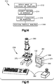
- a particle analysis station 378 includes a microscope 380, an input device 382, and a display 384.
- the input device 382 can be configured as a joystick 383, a keyboard 385, a mouse, any suitable alternative input device, or any desired combination thereof.
- the particle analysis station 378 further includes a processor that is in data communication with the input device 382 and the display 384.
- the processor is configured to operates a stored program that is configured to analyze the particles placed under the microscope 380.
- the stored program can be a Filtrex software program commercially available by Microvision Instruments having a place of business in Evry, France, or any suitable alternative software configured to perform an analysis of the particles as will now be described.
- the method 310 can include the step 312 of obtaining an image 386 of the particles 122 on the filtration substrate 358.
- the obtained image 386 can be a magnified image 386 of at least a portion of the filtration substrate 358 and the particles 122 supported on the filtration substrate 358.
- the filtration substrate 358 and the particles 122 are placed under the microscope 380.
- the sample 375 can be placed under the microscope 380, such that the filtration substrate 358 and the particles 122 are in the field of view. The microscope 380 thus creates the magnified image 386 and outputs the magnified image 386 to the processor, which in turn outputs the magnified image 386 to the display 384.
- the microscope 380 has settings that can be adjusted so as to provide a desirable image 386.
- the magnification can be set as desired, along with illumination that is applied to the filtration substrate and the particles 122. In one example, the magnification can be set at 5 times or any suitable alternative magnification as desired. Further, it can be desirable to provide substantially uniform illumination to the filtration substrate 358.
- the substrate 358 and the particles 122 can be illuminated by the microscope 380 under reflected light illumination. In one embodiment, the filtration substrate 358 and the particles 122 can be illuminated by the microscope 380 under reflected light illumination differential interference contrast microscopy (DIC).
- DIC differential interference contrast microscopy
- the particles 122 are brought into focus on the image 386, such that the particles 122 are visually distinguishable from the filtration substrate 358 on the image 386.
- the software or other software can receive information regarding the sample 375. For instance, the user can input a unique identified or the sample 375. Further, the user can input the weight change of the filtration substrate 358 as described above, along with the number of prosthetic orthopaedic implants 100 from which the particles 122 supported by the filtration substrate 358 were removed.
- the method 310 can include the step 314 of identifying a region of interest 388 that includes the plurality of particles 122.
- the region of interest 388 can include all particles 122 that are supported by the filtration substrate 358.
- the user can input the region of interest 388 on the image 386.
- the plurality of particles 122 can be arranged in groups 123 of particles that are spaced from each other in their respective entireties.
- the quantity of groups 123 of particles 122 can be determined as the number of areas defined inside respective boundary lines described above. Alternatively, at least one of the groups 123 of particles 122 can define a single particle 122.
- the user can identify the outer perimeter 390 of the filtration substrate 358 as defining the region of interest 388.
- the user can identify any suitable shape inside the outer perimeter 390 as the region of interest 388.
- the user can draw a continuous shape that encloses the region of interest 388, or can identify a plurality of points that lie on a continuous shape that defines the region of interest 388.
- the focus and illumination described above remains applied to the region of interest 388, or can be adjusted if desired to within a predetermined illumination range.
- a threshold is applied to the image 386 so as to identify an outer perimeter of each of the groups of at least one particle 122.
- a color threshold can be applied to the image 386 inside the region of interest 388 so as to surround each of the groups 123 of particles 122 with a respective boundary line 392.
- the boundary lines 392 can substantially extend along the outer perimeters of the groups 123 of particles 122, respectively. Accordingly, the software identifies the particles as the area surrounded by the boundary lines 392. Otherwise stated, the area defined inside the boundary lines 392 represent the respective at least one particle 122 or group 123 of particles 122.
- the color threshold can be a gray threshold.
- the filtration substrate 358 media has a lighter grayscale hue than the particles 122.
- the thresholding can be set to eliminate images lighter than the threshold setting.
- the software can display a thresholding selection bar that can be adjusted until only the perimeters of the groups 123 of particles 122 are identified. It should be appreciated that while the thresholding is performed in grayscale in one example, the thresholding can be performed for any suitable color as desired based on the color of the particles 122 and the substrate 358 that supports the particles 122. Further, while the thresholding eliminates images lighter than the threshold setting in one example, the thresholding can alternatively eliminate images darker than the threshold setting in other examples, depending on the colors and hues of the particles 122 and the substrate 358.
- the method 310 advances to step 318 whereby an analysis of the groups of particles 312 can be performed.
- the software can scan the area inside each of the boundary lines 392 generated during the thresholding step 314.
- the software can determine a quantity of the groups 123 of at least one particle 122.
- the software can measure a size of each of the groups 123 of at least one particle 122. For instance, the software can determine a distance of the perimeters, respectively, of the groups 123. Further, the software can determine respective two perpendicular dimensions of the groups 123 of particles 122, respectively.
- the dimensions can be oriented along the upper surface of the filtration substrate 358. Further, the dimensions can include a first dimension that extends along a direction of greatest length of the groups 123 of particles 122, respectively. The dimensions can include a second dimension that is substantially perpendicular to the first direction. In this manner, the respective aspect ratio of each of the groups 123 of particles 122 can be determined. Further an area of each of the groups 123 of particles 122 can be measured along the upper surface of the filtration substrate 358. Thus, a cumulative area of all particles 123 can be calculated as the sum of the areas of all of the groups 123 of particles 122.
- the method 310 can further include the step of comparing the at least one determined characteristic to a predetermined threshold. If the determined characteristic is greater than the threshold characteristic, the prosthetic orthopaedic component 100 can be discarded. If the determined characteristic is within the threshold characteristic, the prosthetic orthopaedic component 100 can be used as an anatomical implant. For example, if the quantity of determined particles 122 is greater than a predetermined quantity of approved particles 122, the prosthetic orthopaedic component 100 can be deemed unsuitable for implantation. Similarly, if the determined weight of the particles 122 is greater than a predetermined weight, the prosthetic orthopaedic component can be deemed unsuitable for implantation.
- the porous structure 120 can be manufactured using any suitable additive manufacturing process that involve the use of digital 3D design data to build up a metal component up in layers by depositing successive layers of material.
- Additive manufacturing processes can include, only by way of example, powder bed fusion printing method (e.g., melting and sintering), cold spray 3D printing, wire feed 3D printing, fused deposition 3D printing, extrusion 3D printing, liquid metal 3D printing, stereolithography 3D printing, binder jetting 3D printing, material jetting 3D printing, and so on.
- a method for producing the porous three-dimensional structure 120 comprises depositing and scanning successive layers of metal powders with a beam to form the porous three-dimensional structure.
- the beam can be an electron beam.
- the beam (or scanning beam) can be a laser beam.
- the metal powders can be sintered to form the porous three-dimensional structure. Alternatively, the metal powders can be melted to form the porous three-dimensional structure.
- the successive layers of metal powders can be deposited onto a solid base (see above for discussion regarding base).
- Another method for producing the porous three-dimensional structure 120 comprises applying a stream of metal particles at a predetermined velocity onto a base to form the porous three-dimensional structure.
- the predetermined velocity can be a critical velocity required for the metal particles to bond upon impacting the base.
- the critical velocity is greater than 340 m/s in some embodiments.
- the method can further include applying a laser at a predetermined power setting onto an area of the base where the stream of metal particles is impacting.
- Another method for producing the porous three-dimensional structure 120 comprises introducing a continuous feed of metal wire onto a base surface and applying a beam at a predetermined power setting to an area where the metal wire contacts the base surface to form a porous three-dimensional structure comprising a plurality of unit cells and having predetermined geometric properties.
- the beam (or scanning beam) can be an electron beam.
- the beam (or scanning beam) can be a laser beam.
- the types of metal wire that can be used include, but are not limited to, titanium, titanium alloys, stainless steel, cobalt chrome alloys, tantalum or niobium wire.
- Another method for producing the porous three-dimensional structure comprises introducing a continuous feed of a polymer material embedded with metal elements onto a base surface.
- the method can further comprise applying heat to an area where the polymer material contacts the base surface to form a porous three-dimensional structure comprising a plurality of unit cells and having predetermined geometric properties.
- the continuous feed of the polymer material can be supplied through a heated nozzle thus eliminating the need to apply heat to the area where the polymer material contacts the base surface to form the porous three-dimensional structure.
- the method can further comprise scanning the porous three-dimensional structure with a beam to burn off the polymer material.
- the beam (or scanning beam) can be an electron beam.
- the beam (or scanning beam) can be a laser beam.
- Another method for producing the porous three-dimensional structure 120 comprises introducing a metal slurry through a nozzle onto a base surface
- the nozzle is heated at a temperature required to bond metallic elements of the metal slurry to the base surface.
- the metal slurry is an aqueous suspension containing metal particles along with one or more additives (liquid or solid) to improve the performance of the manufacturing process or the porous three-dimensional structure.
- the metal slurry is an organic solvent suspension containing metal particles along with one or more additives (liquid or solid) to improve the performance of the manufacturing process or the porous three-dimensional structure.
- Another method for producing the porous three-dimensional structure 120 comprises introducing successive layers of molten metal onto a base surface to form the porous three-dimensional structure.
- the molten metal can be introduced as a continuous stream onto the base surface.
- the molten metal can also be introduced as a stream of discrete molten metal droplets onto the base surface.
- Another method for producing the porous three-dimensional structure 120 comprises applying and photoactivating successive layers of photosensitive polymer embedded with metal elements onto a base surface
- Another method for producing the porous three-dimensional structure comprises depositing and binding successive layers of metal powders with a binder material to form a porous three-dimensional structure comprising a plurality of unit cells and having predetermined geometric properties.
- the method can further include sintering the bound metal powder with a beam.
- the beam (or scanning beam) can be an electron beam.
- the beam (or scanning beam) can be a laser beam.
- the method can further include melting the bound metal powder with a beam.
- the beam (or scanning beam) can be an electron beam.
- the beam (or scanning beam) can be a laser beam.
- Another method for producing the porous three-dimensional structure 120 comprises depositing droplets of a metal material onto a base surface, and applying heat to an area where the metal material contacts the base surface.
- the heat can be applied using a beam (or scanning beam) that can be an electron beam.
- the beam (or scanning beam) can be a laser beam.
- the deposited droplets of metal material can be a metal slurry embedded with metallic elements.
- the metal material can be a metal powder.
Landscapes
- Health & Medical Sciences (AREA)
- Engineering & Computer Science (AREA)
- Manufacturing & Machinery (AREA)
- Heart & Thoracic Surgery (AREA)
- Life Sciences & Earth Sciences (AREA)
- Oral & Maxillofacial Surgery (AREA)
- Transplantation (AREA)
- Biomedical Technology (AREA)
- Orthopedic Medicine & Surgery (AREA)
- Vascular Medicine (AREA)
- Cardiology (AREA)
- Animal Behavior & Ethology (AREA)
- General Health & Medical Sciences (AREA)
- Public Health (AREA)
- Veterinary Medicine (AREA)
- Chemical & Material Sciences (AREA)
- Materials Engineering (AREA)
- Prostheses (AREA)
Abstract
Description
- The present disclosure relates generally to prosthetic orthopaedic components, and more particularly to such components including an additively manufactured structure.
- The embodiments disclosed herein are generally directed towards three-dimensional porous structures for bone ingrowth and methods for producing said structures.
- The field of rapid prototyping and additive manufacturing has seen many advances over the years, particularly for rapid prototyping of articles such as prototype parts and mold dies. These advances have reduced fabrication cost and time, while increasing accuracy of the finished product, versus conventional machining processes, such as those where materials (e.g., metal) start as a block of material, and are consequently machined down to the finished product.
- Examples of modern rapid prototyping/additive manufacturing techniques include sheet lamination, adhesion bonding, laser sintering (or selective laser sintering), laser melting (or selective laser sintering), photopolymerization, droplet deposition, stereolithography, 3D printing, fused deposition modeling, and 3D plotting. Particularly in the areas of selective laser sintering, selective laser melting and 3D printing, the improvement in the production of high density parts has made those techniques useful in designing and accurately producing articles such as highly dense metal parts.
- The additive manufacturing field has created orthopaedic prosthetic components that promote mammalian cell growth and regeneration. Current methods and geometries can control the pore size distribution, which exerts a strong influence on the ingrowth behavior of mammalian cells such as bone, and further produce porous structures having unit cell geometries with pore sizes and porosities simultaneously in the range believed to be beneficial for ingrowth while maintaining structural integrity during the manufacturing process (e.g., 3D printing).
- In accordance with one embodiment, a method is provided for removing at least one particle from an additively manufactured orthopaedic prosthetic component. The method includes the step of submerging at least a portion of the additively manufactured orthopaedic prosthetic component in a liquid. The method further includes the step of sonicating at least a portion of the additively manufactured orthopaedic prosthetic component so as to loosen the at least one particle. The method further includes the step of shaking the additively manufactured orthopaedic prosthetic component so as to evacuate the at least one particle from the additively manufactured orthopaedic prosthetic component.
- In one aspect, the loosened at least one particle is detached from the orthopaedic prosthetic component but disposed in the orthopaedic prosthetic component. The shaking step may be performed while the at least one particle is submerged in the liquid. The sonicating step occurs at a sonication frequency, and shaking step occurs at a shaking frequency that is less than the sonication frequency. The liquid is polar in one embodiment. In another embodiment, the liquid is nonpolar or substantially nonpolar. In one aspect, the method can include the step of increasing a density of the liquid. In one aspect, the method can include the step of adding a salt to the liquid to increase the density. In another aspect, the method further includes the step of adding a dispersion agent to the liquid.
- In one embodiment, the method includes the step of filtering the at least one particle from the fluid. The filtering step causes the liquid to flow through the filtration substrate, and prevents the at least one particle to flow through the filtration substrate during the causing step. The weight of the at least one particle is determined.
- In another embodiment, a method is provided for evaluating an orthopaedic prosthetic component. The method for evaluating the orthopaedic prosthetic component can be performed individually, or in combination with any of the steps associated with the method for removing the at least one particle from the orthopaedic prosthetic component. The orthopaedic prosthetic component includes an additively manufactured structure having a at least one residual particle. The another embodiment or the embodiment method can include the step of obtaining a magnified image of at least a portion of a substrate and at least one particle supported by the substrate, such as the evacuated at least one particle supported by the substrate. The magnified image may be viewed on a display. The at least one particle may be surrounded by at least one boundary line on the image along a respective outer perimeter of the at least one particle. The method may further includes the step of determining at least one of 1) a quantity of the at least one particle and/or a quantity of groups of the at least one particle, 2) a size of the at least one particle, 3) an aspect ratio of the at least one particle, and 4) a weight of the at least one particle. In some embodiments, the method further includes the step of removing the at least one particle from the orthopaedic prosthetic component.
- The method can further include the step of placing the substrate under a microscope so as to generate the magnified image.
- In one aspect, the method further includes the step of thresholding the image so as to define the at least one boundary line, potentially wherein an area defined by the boundary represents at least one particle.
- In one aspect, the at least one particle comprises a plurality of groups of particles spaced from each other in their respective entireties, and the method further includes the step of identifying a region of interest on the substrate that surrounds all of the particles prior to the surrounding step. The substrate can comprise a filter paper or any other substrate suitable for supporting the particles. In another aspect, the method further includes the step of thresholding the region of interest so as to surround the plurality of particles with respective boundary lines.
- In one aspect, the method includes the step of scanning each at least one particle inside each respective at least one boundary line to determine a characteristic of the at least one particle, the at least one characteristic including at least one of 1) a quantity of the at least one particle and/or the quantity of groups of the at least one particle, 2) a size of the at least one particle, and 3) an aspect ratio of the at least one particle. The method can include the step of comparing the determined characteristic against a predetermined threshold. In one aspect, the method further includes the step of providing illumination to the region of interest prior to the thresholding step. The illumination of the particles on the substrate can be adjusted to within a predetermined illumination range. The method may further comprise the step of placing the substrate under a microscope so as to generate the magnified image. The at least one particle may have been evacuated from an orthopaedic prosthetic component or from a plurality of orthopaedic prosthetic components.
- A still further embodiment may provide a method for evaluating an orthopaedic prosthetic component, the method comprising the steps of: obtaining a magnified image of at least a portion of a substrate and at least one particle supported by the substrate, wherein the at least one particle has been removed from the an additively manufactured structure of the orthopaedic prosthetic component; viewing the magnified image on a display; surrounding the at least one particle with at least one boundary line on the image along a respective outer perimeter of the at least one particle, respectively; and determining at least one of 1) a quantity of groups of the at least one particle, 2) a size of the at least one particle, 3) an aspect ratio of the at least one particle, and 4) a weight of the at least one particle. The embodiment may further comprise the step of thresholding the image so as to define the at least one boundary line, wherein the boundary line surrounds an area that represents the particle, the method comprising the step of scanning the area so as to determine at least one of 1) a quantity of groups of the at least one particle, 2) the size of the at least one particle, and 3) the aspect ratio of the at least one particle.
- For a more complete understanding of the principles disclosed herein, and the advantages thereof, reference is now made to the following descriptions taken in conjunction with the accompanying drawings, in which:
-
Fig. 1 is a schematic elevation view of an orthopaedic prosthetic component; -
Fig. 2 is a schematic perspective view of the orthopaedic prosthetic component ofFig. 1 ; -
Fig. 3 is a perspective view of a unit cell of the porous structure of the orthopaedic prosthetic component ofFigs. 1-2 ; -
Fig. 4 is an enlarged portion of the orthopaedic prosthetic component illustrated inFig. 1 as-manufactured, including a plurality of particles to be removed from the orthopaedic prosthetic component; -
Fig. 5 is a flow chart illustrating steps of one embodiment of a method for removing the particles illustrated inFig. 4 , and preparing the particles for analysis in one example; -
Fig. 6 is a schematic assembly view showing the orthopaedic prosthetic component illustrated inFig. 4 disposed in a container and submerged in a liquid; -
Fig. 7A is a schematic assembly view showing a sonication tank that contains the container illustrated inFig. 6 ; -
Fig. 7B is enlarged portion of the orthopaedic prosthetic component similar toFig. 4 , but shown after the sonication step ofFig. 7A , whereby the plurality of particles have been loosened from the orthopaedic prosthetic component; -
Fig. 8A is a schematic assembly view showing the container ofFig. 6 subjected to a shaking step; -
Fig. 8B is enlarged portion of the orthopaedic prosthetic component similar toFig. 7B , but shown after the shaking step ofFig. 7A , whereby the plurality of particles have been separated from the porous structure; -
Fig. 9 is a schematic view of a filtration assembly configured to remove the liquid from the particles; -
Fig. 10 is a top plan view of a filtration substrate of the filtration assembly ofFig. 9 , shown supported on a support structure; -
Fig. 11 is a schematic view of the particles disposed in an oven configured to evaporate the liquid; -
Fig. 12 is a schematic view of the particles disposed in a desiccator configured to decrease a moisture content of the particles; -
Fig. 13 is a schematic top plan view of the particles disposed on the support structure, wherein the support structure is disposed between two glass slides; -
Fig. 14 is a flow chart illustrating steps of one embodiment of a method for analyzing the particles removed from the orthopaedic prosthetic component; -
Fig. 15 is a schematic view of a particle analysis station in one embodiment, including a microscope, a display, and an input device, all in communication with a processor operating a stored program to analyze particles placed in the microscope; -
Fig. 16 is a displayed image of the particles disposed on a substrate, further illustrating the step of identifying a region of interest of the substrate; and -
Fig. 17 is a displayed image of the particles shown encapsulated by a boundary line after performing a color thresholding step. - While the concepts of the present disclosure are susceptible to various modifications and alternative forms, specific exemplary embodiments thereof have been shown by way of example in the drawings and will herein be described in detail. It should be understood, however, that there is no intent to limit the concepts of the present disclosure to the particular forms disclosed, but on the contrary, the intention is to cover all modifications, equivalents, and alternatives falling within the spirit and scope of the invention as defined by the appended claims. Further, the term "at least one" stated structure as used herein can refer to either or both of a single one of the stated structure and a plurality of the stated structure. Additionally, reference herein to a singular "a," "an," or "the" applies with equal force and effect to a plurality unless otherwise indicated. Similarly, reference to a plurality herein applies with equal force and effect to the singular "a," "an," or "the."
- References in the specification to "one embodiment", "an embodiment", "an example embodiment", etc., indicate that the embodiment described may include a particular feature, structure, or characteristic, but every embodiment may not necessarily include the particular feature, structure, or characteristic. Moreover, such phrases are not necessarily referring to the same embodiment. Further, when a particular feature, structure, or characteristic is described in connection with an embodiment, it is submitted that it is within the knowledge of one skilled in the art to effect such feature, structure, or characteristic in connection with other embodiments whether or not explicitly described.
- Further, references in the specification to "about," "approximately," "substantially," derivatives thereof, and words of similar import, when used to describe one or more parameters including sizes, shapes, spatial relationships, distances, directions, and other similar parameters includes the stated parameter in addition to a range up to 10% more and up to 10% less than the stated parameter, including 5% more and 5% less, including 3% more and 3% less, including 1% more and 1% less.
- The present disclosure relates to the additive manufacture of porous three-dimensional metallic structures for orthopaedic prosthetic components, and methods for analyzing the manufacture of such structures. The porous metallic structures promote hard or soft tissue interlocks between prosthetic components implanted in a patient's body and the patient's surrounding hard or soft tissue. For example, when included on an orthopaedic prosthetic component configured to be implanted in a patient's body, the porous three-dimensional metallic structure can be used to provide a porous outer layer of the orthopaedic prosthetic component to form a bone in-growth structure. Alternatively, the porous three-dimensional metallic structure can be used as an implant with the required structural integrity to both fulfill the intended function of the implant and to provide interconnected porosity for tissue interlock (e.g., bone in-growth) with the surrounding tissue. In various embodiments, the types of metals that can be used to form the porous three-dimensional metallic structures can include, but are not limited to, titanium, titanium alloys, stainless steel, cobalt chrome alloys, tantalum or niobium.
- Referring now to
Figs. 1 and 2 , an implantable apparatus such as an orthopaedic implant orprosthetic component 100 is illustrated. Theprosthetic component 100 includes abase 110, a porous three-dimensional structure orlayer 120, and a cone or stem 130 extending away from thebase 110. In the illustrative embodiment, theporous structure 120 surrounds a portion of thebase 110 and a portion of thestem 130. It should be appreciated that theporous structure 120 can be provided as a layer separate from thebase 110 and/or thestem 130. Theporous structure 120 may also provide the entire structure of theprosthetic component 100 or as a coating that surrounds some or all of thebase 110 and/or all of thestem 130. As described in greater detail below, the porous structure includes a plurality of unit cells that define voids or spaces that permit the ingrowth of bone, thereby promoting fixation of theprosthetic component 100 to a patient's bone. - The
orthopaedic implant 100 may be implanted into a tibial bone. For example, thestem 130 can be inserted into the tibial bone, with aledge portion 140 ofimplant 100 resting against a proximal portion of the tibial bone. It should be appreciated that the various porous structures described herein may be incorporated into various orthopaedic implant designs, including, for example, a tibial prosthetic component or a femoral prosthetic component similar to the tibial and femoral components shown inU.S. Patent No. 8,470,047 , which is expressly incorporated herein by reference. The porous structures may also be included in other orthopaedic implant designs, including a patella component shaped to engage a femoral prosthetic component and prosthetic components for use in a hip or shoulder arthroplasty surgery - It should also be noted, for the preceding and going forward, that the base 110 can be any type of structure capable of, for example, contacting, supporting, connecting to or with, or anchoring to or with components of various embodiments herein. The base 110 can include, for example, a metal or non-metal tray, a metal or non-metal baseplate, a metal or non-metal structure that sits on a tray, and so on. The types of metal that can be used to form the base 110 include, but are not limited to, titanium, titanium alloys, stainless steel, cobalt chrome alloys, tantalum or niobium.
- In the illustrative embodiment, the
stem 130 includes asolid region 150, which is coated by aporous region 160 of theporous structure 120. Thesolid region 150 of thestem 130 is anchored to thebase 110 and extends outwardly from theporous structure 120 such that theporous structure 120 surrounds the region ofstem 130 proximal tobase 110. In other embodiments, thestem 130 may be anchored to theporous structure 120. The types of metal that can be used to form thestem 130 include, but are not limited to, titanium, titanium alloys, stainless steel, cobalt chrome alloys, tantalum or niobium. - Referring now to
Fig. 3 , theporous structure 120 of theimplant 100 can comprise a plurality of connected unit cells. Each unit cell defines aunit cell structure 200 that includes a plurality of lattice struts 210 so as to define a firstgeometric structure 230. Each unit cell further defines a plurality ofinternal struts 220 that are disposed within the firstgeometric structure 230 so as to define a plurality of secondgeometric structures 240. In one example, the firstgeometric structure 230 can include the plurality of lattice struts 210. The lattice struts 210 cooperate to define the first geometry. Each secondgeometric structure 240 can be formed by a plurality of theinternal struts 220 and a plurality of the lattice struts 210. Each of the plurality of secondgeometric structures 240 can define an internal volume that is substantially equal to the internal volumes of the other secondgeometric structures 240. In one example, the first geometric structure can be a rhombic dodecahedron, and the second geometric structure can be a rhombic trigonal trapezohedron. It should be appreciated, of course, that the first and second geometric structures can vary as desired. Further, it should be appreciated that the unit cells that make up the casing 33 can have any suitable alternative geometry as desired. For instance, in alternative embodiments, the unit cells can be defined by the plurality of lattice struts 210 withoutinternal struts 220. In other alternative embodiments, the unit cells can be defined by lattice struts 210 andinternal struts 220 that define any suitable geometry, respectively, as desired. Examples of such alternative geometries are described inU.S. Patent Application Serial No. 16/365,557 filed March 26, 2019 - Referring now to
Fig. 4 , the porous three-dimensional structure 120 can be fabricated using any suitable additive manufacturing process as desired, including any of the additive manufacturing processes described below. It is recognized that structures created using additive manufacturing processes can include residual particles as artifacts of the additive printing process. For instance, some additive manufacturing processes involve the deposition of a layer of powder onto a base, and fusing the layer of powder to the base. Subsequent layers of powder are deposited onto the respective preceding layers and subsequently fused to the previous layer to form the porous three-dimensional metallic structures. It is recognized that the manufactured porous three-dimensional structure 120 can include quantities ofparticles 122 that are to be removed prior to use. For instance, the completed part can include residual particles in the form of powder or other particulates. The residual powder can be the product of the additive manufacturing process, and can thus include, but are not limited to, titanium, titanium alloys, stainless steel, cobalt chrome alloys, tantalum or niobium. Alternatively or additionally, the particles can be soil or other debris that may reside on or in the manufacturedstructure 120. - In order to prevent the orthopaedic
prosthetic component 100 from being implanted in a mammalian body while containing theseparticles 122 that can subsequently become dislodged, it is desirable to remove theparticles 122 from the component after the component has been manufactured and prior to implantation. It can be further desirable to analyze the removed particles for quality control purposes, and to ensure that the nature and quantity of the removed particles did not potentially compromise the structural integrity of the additively manufactured porous three-dimensional component. - Referring to
Figs. 4 and5 , amethod 300 is provided for removing theresidual particles 122 from the porous three-dimensional structure 120 for subsequent analysis. Themethod 300 can include thefirst step 302 of cleaning the prostheticorthopaedic component 100 so as to remove theparticles 122 from thecomponent 100. In some circumstances, theparticles 122 can be adhered, bonded, or otherwise attached to thecomponent 100 after the porous three-dimensional structure 120 has been manufactured. For instance, theparticles 122 can be adhered, bonded, or otherwise attached to thebase 110 and/or thestem 130. Alternatively or additionally, theparticles 122 can be adhered, bonded, or otherwise attached to the porous three-dimensional structure 120. - The cleaning
step 302 is configured to remove theparticles 122 from thecomponent 100. In particular, referring toFig. 6 , at least a portion of the orthopaedicprosthetic component 100 is submerged in a solvent 250 that is disposed in anysuitable container 252, such as a beaker or other suitable pourable container. The solvent 250 can be any suitable fluid such as a liquid. In some examples, the liquid can be nonpolar. For instance, the liquid can be water, such as deionized water in some embodiments. Alternatively, the liquid can be substantially polar. For instance, the liquid can be acetone or an alcohol, such as isopropyl alcohol (IPA). Alternatively, the liquid can be oil based. Thus, liquids of different viscosities can be provided. Liquids having high viscosities can increase the transportability of theparticles 122 in the solvent 250. The orthopaedicprosthetic component 100 is placed in thecontainer 252 such that at least the porous three-dimensional structure 120 is submerged in the solvent 250. In some embodiments, an entirety of the orthopaedicprosthetic component 100 can be submerged in the solvent 250. - In some embodiments, it is desirable to remove the
particles 122 from thecomponent 100 so that the particles can be easily removed from thecontainer 252. Thus, one or more agents can be added to the solvent 250 as desired. For instance, a densifier can be added to the solvent 250 that increases the density of the solvent. In one example, the densifier is salt. Increasing the density of the solvent 250 increases the buoyancy of theparticles 122 and reduces the tendency for theparticles 122 to accumulate on the bottom of thecontainer 252. Further, increasing the density of the solvent 250 can increase the transportability of theparticles 122 in the solvent 250. In some embodiments, it is desirable to prevent or reduce aggregation of theparticles 122 in the fluid. Thus, any suitable dispersion agent such as a detergent can be added to the solvent 250 as desired. The dispersing agent increases the dispersion of theparticles 122 in the solvent 250. Any one or more of these additives can be included in the solvent 250 as desired. - In some embodiments, for instance when it is desirable to analyze the
particles 122 of a singleorthopaedic prosthetic component 100, the singleorthopaedic prosthetic component 100 is placed in thecontainer 252. In other embodiments, a plurality of orthopaedicprosthetic components 100 can be placed in thecontainer 252. This embodiment can be particularly suitable when it is desired to efficiently analyze theparticles 122 of a plurality of orthopaedicprosthetic components 100. This embodiment can also be particularly suitable when it is desired to remove, but not analyze, theparticles 122 from a plurality of orthopaedicprosthetic components 100. - Next, referring to
Fig. 7A , the cleaningstep 302 includes thestep 303 of loosening the attachedparticles 122 from the prostheticorthopaedic component 100. In one embodiment, the porousorthopaedic component 100 is sonicated to loosen the attachedparticles 122 from the prostheticorthopaedic component 100. In particular, asonicator 350 may be used to subject thecomponent 100 to high frequency vibration In the illustrative embodiment, thesonicator 350 is activated to deliver high frequency vibration to the porousorthopaedic component 100. Thesonicator 350 can be of the type that includes a sonication tank that contains asonication liquid 351 configured to deliver the high frequency vibration to thecontainer 252. In some examples the high frequency vibration is delivered to thecontainer 252 at an ultrasonic frequency. The sonication liquid can be water, such as reverse osmosis (RO) water. - The
container 252 is placed in the in thesonicator 350 such that thecontainer 252 is disposed in thesonication liquid 351 at a position that prevents thesonication liquid 351 from entering thecontainer 252 during use. Thesonicator 350 is activated to deliver high frequency vibration to thecontainer 252 at any suitable sonication frequency for any suitable duration at any suitable temperature. The temperature can be any suitable temperature as desired. In one example, the temperature can be between about 40 degrees F to approximately 150 degrees F. For instance, the temperature can be room temperature, such as approximately 70 degrees F. The sonication frequency can be within a range from approximately 15 KHz to approximately 400 KHz, or any suitable frequency as desired. In one example, the range of sonication frequencies can be from approximately 25 KHz to approximately 170KHz. During operation, thesonicator 350 delivers the high frequency vibration to thesonication liquid 351 which, in turn, delivers the high frequency vibration to thecontainer 252 and solvent 250. In particular, the sonication frequency causes cavitation in the solvent 250, which drives the solvent to create forces onto the residual particles that cause the particles to loosen from the prostheticorthopaedic component 100. - Further, the sonication process can include delivering high frequency vibrations to the container at a plurality of sonication frequencies. For instance, the
sonicator 350 can deliver a first high frequency vibration to thecontainer 252 at a first sonication frequency. Next, thesonicator 350 can then deliver a second high frequency vibration to thecontainer 252 at a second sonication frequency. The second sonication frequency can be greater than the first sonication frequency. Next, thesonicator 350 can then deliver a third high frequency vibration to thecontainer 252 at a third sonication frequency. The third sonication frequency can be greater than the second sonication frequency. In one example, the first sonication frequency is one of approximately 25 KHz and 40 KHz. The second sonication frequency is approximately 72 KHz. The third sonication frequency is approximately 104 KHz. The first, second, and third sonication frequencies can be delivered for any suitable time duration as desired. In one example, the time direction can be approximately 10 minutes, though longer or shorter time durations are also envisioned. It is recognized that lower sonication frequencies are more suitable to loosen large particles, and higher sonication frequencies are more suitable to loosen small particles. - Because the orthopaedic
prosthetic component 100 is disposed in thecontainer 252 during the sonication process, theresidual particles 122 can be easily retrieved from thecontainer 252 if desired. Alternatively, it should be appreciated that the orthopaedicprosthetic component 100 can be placed directly into thesonication liquid 351, and disposed in thesonication liquid 351 during the sonication process. - Referring now to
Fig. 7B , and as described above, the sonication has causedresidual particles 122 that were attached to the prostheticorthopaedic component 100 to become detached and loosened from the prostheticorthopaedic component 100. Further, it is recognized that in some examples at least some of theparticles 122 can be free from attachment to the prostheticorthopaedic component 100, but lodged in thecomponent 100, prior to thecleaning step 302. It is appreciated, however, that at least some of the loosenedparticles 122 may not be evacuated from the orthopaedicprosthetic component 100. For instance, the loosenedparticles 122 may be trapped in the orthopaedic prosthetic component. In one example, theinternal struts 220 and lattice struts 210 can prevent the loosenedparticles 122 from traveling out of the prostheticorthopaedic component 100, and in particular out of the porous three-dimensional structure 120. - Accordingly, referring now to
Figs. 5 and8A , the cleaningstep 302 can include astep 305 of evacuating theparticle 122 from the orthopaedicprosthetic component 100. The loosenedparticles 122 may have become loosened during the sonicating step. Alternatively, as noted above, some or all theparticles 122 may have been loose from the orthopaedic prosthetic component prior to sonicating. The evacuating step can include the step of shaking thecontainer 252 in order to cause theloose particles 122 to flow out from the prostheticorthopaedic component 100 in the solvent 250. - The shaking step can include the step of attaching the
container 122 to asupport member 352 of ashaker apparatus 354. In one embodiment, thecontainer 122 can be placed in thesupport member 352, such that thesupport member 352 firmly supports thecontainer 122. Thus, as thesupport member 352 causes thecontainer 122 to shake, thesupport member 352 prevents unintended movement of thecontainer 122 during the shaking step. Thus, the shaking step can transport the particles away from the prostheticorthopaedic component 100. During operation, theshaker apparatus 354 causes thesupport member 352 to shake thecontainer 122. Shaking of thecontainer 122 causes the solvent 250 to flow inside thecontainer 122, which drives theparticles 122 to evacuate the prostheticorthopaedic component 100. The shaking step can be performed for any duration of time as desired, such as approximately ten minutes in one example. After the shaking step has been completed, the loosenedparticles 122 that have been evacuated from the prostheticorthopaedic component 100 are suspended in the solvent 250 in one embodiment. In other embodiments, at least some of the loosenedparticles 122 can be disposed on the base of thecontainer 122, and subsequently removed from thecontainer 122. The shaking step can cause thecontainer 122 to undergo repeated physical reciprocal motion at a shaking frequency of between approximately 30 and approximately 300 reciprocal (e.g., back and forth) movements per minute, such as between approximately 35 and 100 reciprocal movements per minutes, for instance approximately 60 reciprocal movements per minute. Thus, the shaking frequency is less than the sonication frequency. It is appreciated that the shaking frequency can be adjusted depending on many factors, such as the geometry of the orthopaedicprosthetic component 100 and various characteristics of the particles. During operation, the shaking frequency causes a gentle cavitation in the solvent 250, which creates a flow exchange between the solvent 250 within the orthopaedicprosthetic component 100 and the solvent that surrounds the orthopaedicprosthetic component 100. The solvent 250 within the orthopaedicprosthetic component 100 can contain one or moreresidual particles 122 that have loosened from the orthopaedicprosthetic component 100 during the sonication step. The flow exchange causes the solvent 250 within the orthopaedicprosthetic component 100, and thus the loosenedparticles 122 disposed in the solvent 250, to be transported out of the prostheticorthopaedic component 100. - In this regard, the sonication step can be referred to as a high frequency vibration of the prosthetic orthopaedic component which can be defined by the sonication frequency as described above, and the shaking step can be referred to as a low frequency vibration of the prosthetic orthopaedic component which can be defined by the shaking frequency as described above. The low frequency of vibration is less than the high frequency vibration. For instance, the high frequency vibration can be greater than 500 times the low frequency vibration, for instance greater 1000 times the low frequency vibration. Thus, the method can include the step of subjecting at least a portion of the prosthetic
orthopaedic component 100 up to an entirety of the prosthetic orthopaedic component to the high frequency of vibration so as to loosen at least one of the attachedparticles 122 from the prostheticorthopaedic component 100, and subsequently subjecting the at least a portion of the prostheticorthopaedic component 100 up to an entirety of the prosthetic orthopaedic component to the low frequency of vibration so as to evacuate the loosen at least one of the attachedparticles 122 from the orthopaedicprosthetic component 100. - Referring again to
Fig. 5 , while thecleaning step 302 can include the sonicating and shakingsteps particles 122 from the prostheticorthopaedic component 100. For instance, a stream of liquid or other vacuum mechanism can be directed at the prostheticorthopaedic component 100 at a force and for a duration sufficient to loosen and evacuate theparticles 122 from the prostheticorthopaedic component 100. The stream of liquid or vacuum can replace either or both of the sonicating and shaking steps. Of course, it can be desirable to place a container at a location that receives theparticles 122 that are removed in response to the stream of liquid. Once theparticles 122 have been collected in a suitable container, themethod 300 can proceed to step 304 of filtering theparticles 122 from the solvent 250. - Referring now to
Figs. 7B and9 , afiltration assembly 356 is configured to filter the removed particles 112 from the solvent 250. In particular, the solvent 250 can be driven through afiltration substrate 358, such that the particles 112 accumulate on thesubstrate 358. Thesubstrate 358 is thus porous with respect to the solvent 250, but nonporous with respect to the particles 112. Further, thefiltration assembly 356 can include an air pressure source in the form of anair pump 368 that delivers air pressure to the solvent 250 that drives the solvent through thesubstrate 358. In one embodiment, theair pressure source 368 is a vacuum that delivers negative pressure to the solvent 250, thereby drawing the solvent 250 through thesubstrate 358 as the solvent is delivered to thesubstrate 358. Alternatively, the air pressure source can be a positive air pump that forces the solvent 250 through thesubstrate 358 as the solvent is delivered to thesubstrate 358. - Prior to the filtration step, the
filtration substrate 358 is weighed. As will be described in more detail below, knowing the weight of thefiltration substrate 358 provides for a more accurate subsequent determination of the weight of the particles 112. The filtration assembly 256 further includes aporous support member 360 that is configured to support thefiltration substrate 358. In particular, thefiltration substrate 358 is placed on top of theporous support member 360. Thefiltration substrate 358 can further be fastened, such as clamped, to theporous support member 360. Theporous support member 360 is porous to air and the solvent 250, such that the solvent that is drawn through thefiltration substrate 358 is also drawn through theporous support member 360. In one example, theporous support member 360 can be a screen or mesh. Thefiltration substrate 358 can be configured as filter paper. - The
porous support member 360 can be in fluid communication with afirst container 362 that is configured to receive the solvent 250 that passes through theporous support member 360. For instance, theporous support member 360 can be supported directly or indirectly by thefirst container 362. Further, in one embodiment thefiltration assembly 356 includes aninlet 363 that is configured to receive the solvent 250 andparticles 122, and directs the solvent 250 to travel through theporous support member 360 and into thefirst container 362. Thefiltration assembly 356 can further include atrap container 364 that is in fluid communication with thefirst container 362. In particular, thefiltration assembly 356 includes a drain and afirst conduit 366 that extends from the drain of thefirst container 362 to an inlet of thetrap container 364. When the level of liquid in thefirst container 362 rises to the level of the drain, the liquid in thefirst container 362 travels along theconduit 366 from thefirst container 362 to thetrap container 364. The inlet of thetrap container 364 can be disposed below the outlet of thefirst container 362. - The
filtration assembly 356 further includes anair pump 368 that is in fluid communication with thetrap container 364. For instance, thefiltration assembly 356 can include asecond conduit 370 that extends from thetrap container 364 to theair pump 368. Thefiltration assembly 356 can further include atrap filter 371 disposed in thesecond conduit 370 that allows air to pass through, but is nonporous with respect to the solvent 250 and water. - During operation, the solvent 250 and
particles 122 contained therein are delivered to theinlet 363. The inlet can be configured as a funnel or any suitable container with an open end that receives the liquid andparticles 122 disposed in the liquid. Thus, the solvent 250 can be poured from the container 252 (seeFig. 6 ) into the inlet, such that the solvent 250 and theparticles 122 are delivered tofiltration substrate 358. If desired, an additional quantity of liquid, sch as deionized water, can be sprayed or squirted against the interior walls of thecontainer 252 and emptied into theinlet 363. Thus,particles 122 that might have still remained on a wall of thecontainer 252 is delivered into the funnel. Because thefiltration substrate 358 is not sufficiently porous to allow theparticles 122 to pass through, theparticles 122 amass on an outer surface of thefiltration substrate 358 as the liquid flows through thefiltration substrate 358. - The
air pump 368 is activated so as to induce a negative pressure that drives the solvent 250 and any additional liquid disposed in the inlet 363 (collectively referred to as liquid) through thefiltration substrate 358. In particular, the negative pressure induced by thepump 368 is in fluid communication with thefiltration substrate 358 through thefirst container 362, thefirst conduit 366, thetrap container 364, and thesecond conduit 370. Theparticles 122 remain on thefiltration substrate 358 as the liquid flows through thefiltration substrate 358. The liquid flows from thefiltration substrate 358 through theporous support member 360, and into thefirst container 362. If the liquid rises in thefirst container 362 to a level equal to the drain of thefirst container 362, the liquid travels through theconduit 366 into thetrap container 364, thereby maintaining a negative pressure differential across thefiltration substrate 358 as induced by theair pump 368. Once the liquid has been drained from theinlet 363, additional liquid such as deionized water can be sprayed or squirted to the walls of the funnel in order to ensure thatparticles 122 that remain on the funnel walls are delivered to thefiltration substrate 358. Theair pump 368 can be deactivated once substantially all liquid has been removed from the funnel. - Next, referring again to
Fig. 5 , it is recognized that theparticles 122 and thefiltration substrate 358 are wet after completion of thefiltering step 304. Therefore, theparticles 122 are dried atstep 306. In particular, as illustrated inFig. 11 , thefiltration substrate 358 is removed from the filtration assembly and placed into anoven 372 that can heat thefiltration substrate 358 to a temperature for a duration of time that is suitable to dry thesubstrate 358 and the particles 112 disposed on the substrate. In particular, thefiltration substrate 358 is removed from thefiltration assembly 356 and placed on anoptical support member 374. In one embodiment, thesupport member 374 is configured as an opticallytransparent support member 374. For instance, as shown onFig. 10 , the opticallytransparent support member 374 can be a glass slide. As will be described in more detail below, theglass slide 374 is optically transparent that is suitable to allow theparticles 122 to be examined under a microscope. Theglass slide 374 supports a bottom surface of thefiltration substrate 358, while theparticles 122 are disposed on a top surface of thefiltration substrate 358 that is opposite the bottom surface. - Referring again to
Fig. 11 , theoven 372 is heated to any temperature suitable for drying the liquid from thefiltration substrate 358. For instance, the oven can be heated to any temperature that ranges from approximately 100 degrees F to approximately 550 degrees F. It can be desirable to heat the oven to a low temperature setting for the purposes of drying the liquid from thefiltration substrate 358, particularly when the liquid is water. Accordingly, in one example, the oven can be set to a range from approximately 125 degrees F to approximately 200 degrees F, such as approximately 150 degrees F. Once theoven 372 has reached the desired temperature, theglass slide 374 andfiltration substrate 358 are placed into theoven 372 for a duration suitable to allow the liquid to dry. For instance, the duration of time can be approximately ten minutes or until thefiltration substrate 358 andparticles 122 have dried. - Next, referring to
Fig. 12 , the dryingstep 306 can further include the step of desiccating thefiltration substrate 358 and theparticles 122. In particular, theglass slide 374 is removed from theoven 372 and placed in adesiccator 376 to remove remaining moisture from thefiltration substrate 358 andparticles 122. The temperature of thedesiccator 376 is brought to room temperature to correspondingly bring thesubstrate 358 andparticles 122 to room temperature and ensure an accurate subsequent weight measurement. Once theglass slide 374 has been removed from thedesiccator 376, thefiltration substrate 358 is weighed. The difference in weight of thefiltration substrate 358 prior to thefiltering step 304 and after the dryingstep 306 provides afiltration substrate 358 weight difference that provides the weight of theparticles 122. The weight of theparticles 122 can correspond to theparticles 122 of a single prostheticorthopaedic component 100. Alternatively, as described above, a plurality of prostheticorthopaedic components 100 can be placed in thecontainer 252. Thus, the weight of theparticles 122 can correspond to the particles of a plurality oforthopaedic components 100. - Next, referring to
Fig. 14 , amethod 310 of analyzing the prostheticorthopaedic component 100, and inparticular particles 122 from the prostheticorthopaedic component 100, can be performed after themethod 300 has been completed. The method can determine at least one or more characteristic to all of the characteristics of 1) the quantity ofparticles 122 disposed on thefiltration substrate 358, 2) the sizes of theparticles 122, and 3) the aspect ratios of theparticles 122. Additionally, the weight of the at least oneparticle 122 can be determined in the manner described above. As will be appreciated from the description below, themethod 300 includes the step of viewing theparticles 122 under microscope. Accordingly, as illustrated inFig. 13 , after thefiltration substrate 358 supporting theparticles 122 has been weighed, thefiltration substrate 358 is placed between opticallytransparent support members 374 so as to define asample 375, which can be configured as glass slides as described above. Thus, the bottom surface of thefiltration substrate 358 is supported by afirst glass slide 374, and asecond glass slide 374 can cover the top surface of thefiltration substrate 358. The second glass slide can be attached to the first glass slide, so that thefiltration substrate 358 is captured between the first and second glass slides 374. The first and second glass slides 374 are then attached to each other, for instance using anysuitable adhesive 377 such as tape. While it is appreciated that theparticles 122 can be disposed on thefiltration substrate 358 when placed under the microscope in one example, it should be appreciated that theparticles 122 can be transferred from thefiltration substrate 358 to any alternative substrate suitable for supporting theparticles 122 as desired. - As illustrated in
Fig. 15 , aparticle analysis station 378 includes amicroscope 380, aninput device 382, and adisplay 384. Theinput device 382 can be configured as a joystick 383, a keyboard 385, a mouse, any suitable alternative input device, or any desired combination thereof. Theparticle analysis station 378 further includes a processor that is in data communication with theinput device 382 and thedisplay 384. The processor is configured to operates a stored program that is configured to analyze the particles placed under themicroscope 380. The stored program can be a Filtrex software program commercially available by Microvision Instruments having a place of business in Evry, France, or any suitable alternative software configured to perform an analysis of the particles as will now be described. - Referring now to
Figs. 14-16 , themethod 310 can include thestep 312 of obtaining animage 386 of theparticles 122 on thefiltration substrate 358. In particular, the obtainedimage 386 can be a magnifiedimage 386 of at least a portion of thefiltration substrate 358 and theparticles 122 supported on thefiltration substrate 358. In some embodiments, it is desirable for the magnifiedimage 386 to include an entirety of thefiltration substrate 358 to ensure that theimage 386 includes allparticles 122 supported by thefiltration substrate 358. For instance, thefiltration substrate 358 and theparticles 122 are placed under themicroscope 380. In one example, thesample 375 can be placed under themicroscope 380, such that thefiltration substrate 358 and theparticles 122 are in the field of view. Themicroscope 380 thus creates the magnifiedimage 386 and outputs the magnifiedimage 386 to the processor, which in turn outputs the magnifiedimage 386 to thedisplay 384. - The
microscope 380 has settings that can be adjusted so as to provide adesirable image 386. For instance, the magnification can be set as desired, along with illumination that is applied to the filtration substrate and theparticles 122. In one example, the magnification can be set at 5 times or any suitable alternative magnification as desired. Further, it can be desirable to provide substantially uniform illumination to thefiltration substrate 358. Thesubstrate 358 and theparticles 122 can be illuminated by themicroscope 380 under reflected light illumination. In one embodiment, thefiltration substrate 358 and theparticles 122 can be illuminated by themicroscope 380 under reflected light illumination differential interference contrast microscopy (DIC). Theparticles 122 are brought into focus on theimage 386, such that theparticles 122 are visually distinguishable from thefiltration substrate 358 on theimage 386. - The software or other software can receive information regarding the
sample 375. For instance, the user can input a unique identified or thesample 375. Further, the user can input the weight change of thefiltration substrate 358 as described above, along with the number of prostheticorthopaedic implants 100 from which theparticles 122 supported by thefiltration substrate 358 were removed. - Next, referring again to
Figs. 14 and16 , themethod 310 can include thestep 314 of identifying a region ofinterest 388 that includes the plurality ofparticles 122. The region ofinterest 388 can include allparticles 122 that are supported by thefiltration substrate 358. The user can input the region ofinterest 388 on theimage 386. The plurality ofparticles 122 can be arranged ingroups 123 of particles that are spaced from each other in their respective entireties. The quantity ofgroups 123 ofparticles 122 can be determined as the number of areas defined inside respective boundary lines described above. Alternatively, at least one of thegroups 123 ofparticles 122 can define asingle particle 122. In one example, the user can identify theouter perimeter 390 of thefiltration substrate 358 as defining the region ofinterest 388. Alternatively, the user can identify any suitable shape inside theouter perimeter 390 as the region ofinterest 388. The user can draw a continuous shape that encloses the region ofinterest 388, or can identify a plurality of points that lie on a continuous shape that defines the region ofinterest 388. The focus and illumination described above remains applied to the region ofinterest 388, or can be adjusted if desired to within a predetermined illumination range. - Next, referring to
Figs. 14 and17 , at step 316 a threshold is applied to theimage 386 so as to identify an outer perimeter of each of the groups of at least oneparticle 122. In particular, a color threshold can be applied to theimage 386 inside the region ofinterest 388 so as to surround each of thegroups 123 ofparticles 122 with arespective boundary line 392. In one example, theboundary lines 392 can substantially extend along the outer perimeters of thegroups 123 ofparticles 122, respectively. Accordingly, the software identifies the particles as the area surrounded by the boundary lines 392. Otherwise stated, the area defined inside theboundary lines 392 represent the respective at least oneparticle 122 orgroup 123 ofparticles 122. Analysis on size and shape of thegroups 123 ofparticles 122 can thus be performed based on a corresponding analysis of the area surrounded by the boundary lines 392. In one example, the color threshold can be a gray threshold. In particular, it is recognized that in grayscale, thefiltration substrate 358 media has a lighter grayscale hue than theparticles 122. Thus, the thresholding can be set to eliminate images lighter than the threshold setting. The software can display a thresholding selection bar that can be adjusted until only the perimeters of thegroups 123 ofparticles 122 are identified. It should be appreciated that while the thresholding is performed in grayscale in one example, the thresholding can be performed for any suitable color as desired based on the color of theparticles 122 and thesubstrate 358 that supports theparticles 122. Further, while the thresholding eliminates images lighter than the threshold setting in one example, the thresholding can alternatively eliminate images darker than the threshold setting in other examples, depending on the colors and hues of theparticles 122 and thesubstrate 358. - Referring again to
Fig. 14 , once the perimeters of thegroups 123 ofparticles 122 have been identified at thethresholding step 316, themethod 310 advances to step 318 whereby an analysis of the groups ofparticles 312 can be performed. In particular, the software can scan the area inside each of theboundary lines 392 generated during thethresholding step 314. In this regard, the software can determine a quantity of thegroups 123 of at least oneparticle 122. Further, the software can measure a size of each of thegroups 123 of at least oneparticle 122. For instance, the software can determine a distance of the perimeters, respectively, of thegroups 123. Further, the software can determine respective two perpendicular dimensions of thegroups 123 ofparticles 122, respectively. The dimensions can be oriented along the upper surface of thefiltration substrate 358. Further, the dimensions can include a first dimension that extends along a direction of greatest length of thegroups 123 ofparticles 122, respectively. The dimensions can include a second dimension that is substantially perpendicular to the first direction. In this manner, the respective aspect ratio of each of thegroups 123 ofparticles 122 can be determined. Further an area of each of thegroups 123 ofparticles 122 can be measured along the upper surface of thefiltration substrate 358. Thus, a cumulative area of allparticles 123 can be calculated as the sum of the areas of all of thegroups 123 ofparticles 122. - The
method 310 can further include the step of comparing the at least one determined characteristic to a predetermined threshold. If the determined characteristic is greater than the threshold characteristic, the prostheticorthopaedic component 100 can be discarded. If the determined characteristic is within the threshold characteristic, the prostheticorthopaedic component 100 can be used as an anatomical implant. For example, if the quantity ofdetermined particles 122 is greater than a predetermined quantity of approvedparticles 122, the prostheticorthopaedic component 100 can be deemed unsuitable for implantation. Similarly, if the determined weight of theparticles 122 is greater than a predetermined weight, the prosthetic orthopaedic component can be deemed unsuitable for implantation. - As described above, the
porous structure 120 can be manufactured using any suitable additive manufacturing process that involve the use of digital 3D design data to build up a metal component up in layers by depositing successive layers of material. Additive manufacturing processes can include, only by way of example, powder bed fusion printing method (e.g., melting and sintering), cold spray 3D printing, wire feed 3D printing, fused deposition 3D printing, extrusion 3D printing, liquid metal 3D printing, stereolithography 3D printing, binder jetting 3D printing, material jetting 3D printing, and so on. - In various embodiments, a method for producing the porous three-
dimensional structure 120 comprises depositing and scanning successive layers of metal powders with a beam to form the porous three-dimensional structure. The beam (or scanning beam) can be an electron beam. The beam (or scanning beam) can be a laser beam. The metal powders can be sintered to form the porous three-dimensional structure. Alternatively, the metal powders can be melted to form the porous three-dimensional structure. The successive layers of metal powders can be deposited onto a solid base (see above for discussion regarding base). - Another method for producing the porous three-
dimensional structure 120 comprises applying a stream of metal particles at a predetermined velocity onto a base to form the porous three-dimensional structure. The predetermined velocity can be a critical velocity required for the metal particles to bond upon impacting the base. The critical velocity is greater than 340 m/s in some embodiments. The method can further include applying a laser at a predetermined power setting onto an area of the base where the stream of metal particles is impacting. - Another method for producing the porous three-
dimensional structure 120 comprises introducing a continuous feed of metal wire onto a base surface and applying a beam at a predetermined power setting to an area where the metal wire contacts the base surface to form a porous three-dimensional structure comprising a plurality of unit cells and having predetermined geometric properties. The beam (or scanning beam) can be an electron beam. The beam (or scanning beam) can be a laser beam. In various embodiments, the types of metal wire that can be used include, but are not limited to, titanium, titanium alloys, stainless steel, cobalt chrome alloys, tantalum or niobium wire. - Another method for producing the porous three-dimensional structure comprises introducing a continuous feed of a polymer material embedded with metal elements onto a base surface. The method can further comprise applying heat to an area where the polymer material contacts the base surface to form a porous three-dimensional structure comprising a plurality of unit cells and having predetermined geometric properties. In various embodiments, the continuous feed of the polymer material can be supplied through a heated nozzle thus eliminating the need to apply heat to the area where the polymer material contacts the base surface to form the porous three-dimensional structure. The method can further comprise scanning the porous three-dimensional structure with a beam to burn off the polymer material. The beam (or scanning beam) can be an electron beam. The beam (or scanning beam) can be a laser beam.
- Another method for producing the porous three-
dimensional structure 120 comprises introducing a metal slurry through a nozzle onto a base surface In various embodiments, the nozzle is heated at a temperature required to bond metallic elements of the metal slurry to the base surface. In various embodiments, the metal slurry is an aqueous suspension containing metal particles along with one or more additives (liquid or solid) to improve the performance of the manufacturing process or the porous three-dimensional structure. In various embodiments, the metal slurry is an organic solvent suspension containing metal particles along with one or more additives (liquid or solid) to improve the performance of the manufacturing process or the porous three-dimensional structure. - Another method for producing the porous three-
dimensional structure 120 comprises introducing successive layers of molten metal onto a base surface to form the porous three-dimensional structure. The molten metal can be introduced as a continuous stream onto the base surface. The molten metal can also be introduced as a stream of discrete molten metal droplets onto the base surface. - Another method for producing the porous three-
dimensional structure 120 comprises applying and photoactivating successive layers of photosensitive polymer embedded with metal elements onto a base surface - Another method for producing the porous three-dimensional structure comprises depositing and binding successive layers of metal powders with a binder material to form a porous three-dimensional structure comprising a plurality of unit cells and having predetermined geometric properties. The method can further include sintering the bound metal powder with a beam. The beam (or scanning beam) can be an electron beam. The beam (or scanning beam) can be a laser beam. The method can further include melting the bound metal powder with a beam. The beam (or scanning beam) can be an electron beam. The beam (or scanning beam) can be a laser beam.
- Another method for producing the porous three-
dimensional structure 120 comprises depositing droplets of a metal material onto a base surface, and applying heat to an area where the metal material contacts the base surface. The heat can be applied using a beam (or scanning beam) that can be an electron beam. The beam (or scanning beam) can be a laser beam. The deposited droplets of metal material can be a metal slurry embedded with metallic elements. The metal material can be a metal powder. - While the disclosure has been illustrated and described in detail in the drawings and foregoing description, such an illustration and description is to be considered as exemplary and not restrictive in character, it being understood that only illustrative embodiments have been shown and described and that all changes and modifications that come within the spirit of the disclosure are desired to be protected.
- There are a plurality of advantages of the present disclosure arising from the various features of the method, apparatus, and system described herein. It will be noted that alternative embodiments of the method, apparatus, and system of the present disclosure may not include all of the features described yet still benefit from at least some of the advantages of such features. Those of ordinary skill in the art may readily devise their own implementations of the method, apparatus, and system that incorporate one or more of the features of the present invention and fall within the spirit and scope of the present disclosure as defined by the appended claims.
Claims (14)
- A method for removing at least one particle from an additively manufactured orthopaedic prosthetic component, the method comprising the steps of:submersing at least a portion of the additively manufactured orthopaedic in a liquid;sonicating at least a portion of the additively manufactured orthopaedic prosthetic component so as to loosen the at least one particle; andshaking the additively manufactured orthopaedic prosthetic component to a low frequency vibration that is less than the high level vibration so as to evacuate the loosened at least one particle from the additively manufactured orthopaedic prosthetic component.
- The method of claim 1, wherein the loosened at least one particle is detached from the orthopaedic prosthetic component but disposed in the orthopaedic prosthetic component.
- The method of claim 1, comprising performing the shaking step while the at least one particle is submerged in the liquid.
- The method of claim 1, wherein the sonicating step occurs at a sonication frequency, and the second subjecting step occurs at a shaking frequency that is less than the sonication frequency.
- The method of claim 1, wherein the liquid is polar or wherein the liquid is substantially nonpolar.
- The method of claim 1, further comprising the step of increasing a density of the liquid, optionally wherein the increasing step comprises adding a salt to the liquid, optionally further comprising the step of adding a dispersion agent to the liquid.
- The method of claim 1, further comprising the step of filtering the at least one particle from the fluid, optionally wherein the filtering step comprises causing the liquid to flow through the filtration substrate, and preventing the at least one particle to flow through the filtration substrate during the causing step.
- The method of claim 7, further comprising the step of determining a weight of the at least one particle.
- The method of claim 1, further comprising the steps of:obtaining a magnified image of at least a portion of a substrate and the evacuated at least one particle supported by the substrate;viewing the magnified image on a display;surrounding the at least one particle with at least one boundary line on the image along a respective outer perimeter of the at least one particle, respectively; anddetermining at least one of 1) a quantity of groups of the at least one particle, 2) a size of the at least one particle, 3) an aspect ratio of the at least one particle, and 4) a weight of the at least one particle.
- The method of claim 9, further comprising the step of thresholding the image so as to define the at least one boundary line, wherein an area defined by the boundary represents the at least one particle.
- The method of claim 9, wherein the at least one particle comprises a plurality of groups of particles spaced from each other in their respective entireties, the method further comprising the step of identifying a region of interest on the substrate that surrounds all of the particles prior to the surrounding step.
- The method of claim 9, further comprising the step of scanning each at least one particle inside each respective at least one boundary line to determine a characteristic of the at least one particle, the at least one characteristic including at least one of 1) the quantity of groups of the at least one particle, 2) the size of the at least one particle, and 3) the aspect ratio of the at least one particle.
- The method of claim 12, further comprising the step of comparing the determined characteristic against a predetermined threshold.
- The method of claim 9, further comprising the step of placing the substrate under a microscope so as to generate the magnified image.
Applications Claiming Priority (1)
| Application Number | Priority Date | Filing Date | Title |
|---|---|---|---|
| US16/801,579 US11806955B2 (en) | 2020-02-26 | 2020-02-26 | Method for testing additively manufactured orthopaedic prosthetic components |
Publications (2)
| Publication Number | Publication Date |
|---|---|
| EP3871636A1 true EP3871636A1 (en) | 2021-09-01 |
| EP3871636B1 EP3871636B1 (en) | 2025-03-19 |
Family
ID=74797774
Family Applications (1)
| Application Number | Title | Priority Date | Filing Date |
|---|---|---|---|
| EP21159521.0A Active EP3871636B1 (en) | 2020-02-26 | 2021-02-26 | Method for cleaning additively manufactured orthopaedic prosthetic components |
Country Status (2)
| Country | Link |
|---|---|
| US (1) | US11806955B2 (en) |
| EP (1) | EP3871636B1 (en) |
Citations (5)
| Publication number | Priority date | Publication date | Assignee | Title |
|---|---|---|---|---|
| US5641323A (en) * | 1994-02-18 | 1997-06-24 | Johnson & Johnson Professional, Inc. | Self-lubricating implantable articulation member |
| EP0836453A1 (en) * | 1995-06-07 | 1998-04-22 | Massachusetts Institute Of Technology | Vascularized tissue regeneration matrices formed by solid free-form fabrication methods |
| EP1418013A1 (en) * | 2002-11-08 | 2004-05-12 | Howmedica Osteonics Corp. | Laser-produced porous surface |
| US20060004466A1 (en) * | 2004-06-28 | 2006-01-05 | Glocker David A | Porous coatings for biomedical implants |
| US8470047B2 (en) | 2007-09-25 | 2013-06-25 | Depuy (Ireland) | Fixed-bearing knee prosthesis |
Family Cites Families (9)
| Publication number | Priority date | Publication date | Assignee | Title |
|---|---|---|---|---|
| FR2960698B1 (en) | 2010-05-27 | 2013-05-10 | Centre Nat Rech Scient | ADJUSTABLE CATHODOLUMINESCENCE DETECTION SYSTEM AND MICROSCOPE USING SUCH A SYSTEM. |
| US8470525B2 (en) | 2011-09-02 | 2013-06-25 | Agentase, Llc | Method for analyzing air |
| US10458896B2 (en) | 2013-05-28 | 2019-10-29 | Chemometec A/S | Image forming cytometer |
| US9816911B2 (en) | 2013-11-14 | 2017-11-14 | Beckman Coulter, Inc. | Flow cytometry optics |
| US9952133B2 (en) | 2015-10-08 | 2018-04-24 | Kinetic River Corp. | Particle analysis and sorting apparatus and methods |
| US9658148B2 (en) | 2014-10-09 | 2017-05-23 | Kinetic River Corp. | Particle analysis and sorting apparatus and methods |
| FR3032036B1 (en) | 2015-01-27 | 2018-09-07 | Cnrs - Centre National De La Recherche Scientifique | METHODS AND DEVICES FOR DETECTING SURFACE CONTAMINATION BY FREE-AIR EVOLVING PARTICLES |
| GB201808639D0 (en) * | 2018-05-25 | 2018-07-11 | Additive Manufacturing Tech Ltd | Additive manufacturing |
| CN109701085A (en) * | 2019-02-21 | 2019-05-03 | 刘昕 | Preparation method of 3D printed porous titanium scaffold strontium-doped hydroxyapatite bioactive coating |
-
2020
- 2020-02-26 US US16/801,579 patent/US11806955B2/en active Active
-
2021
- 2021-02-26 EP EP21159521.0A patent/EP3871636B1/en active Active
Patent Citations (5)
| Publication number | Priority date | Publication date | Assignee | Title |
|---|---|---|---|---|
| US5641323A (en) * | 1994-02-18 | 1997-06-24 | Johnson & Johnson Professional, Inc. | Self-lubricating implantable articulation member |
| EP0836453A1 (en) * | 1995-06-07 | 1998-04-22 | Massachusetts Institute Of Technology | Vascularized tissue regeneration matrices formed by solid free-form fabrication methods |
| EP1418013A1 (en) * | 2002-11-08 | 2004-05-12 | Howmedica Osteonics Corp. | Laser-produced porous surface |
| US20060004466A1 (en) * | 2004-06-28 | 2006-01-05 | Glocker David A | Porous coatings for biomedical implants |
| US8470047B2 (en) | 2007-09-25 | 2013-06-25 | Depuy (Ireland) | Fixed-bearing knee prosthesis |
Also Published As
| Publication number | Publication date |
|---|---|
| EP3871636B1 (en) | 2025-03-19 |
| US20210260841A1 (en) | 2021-08-26 |
| US11806955B2 (en) | 2023-11-07 |
Similar Documents
| Publication | Publication Date | Title |
|---|---|---|
| US11510783B2 (en) | Laser-produced porous surface | |
| Bahraminasab | Challenges on optimization of 3D-printed bone scaffolds | |
| JP7480057B2 (en) | Three-dimensional porous structures for bone ingrowth and methods of manufacture - Patents.com | |
| Touri et al. | Additive manufacturing of biomaterials− the evolution of rapid prototyping | |
| Lee et al. | Scaffold fabrication by indirect three-dimensional printing | |
| EP2195131B1 (en) | Method for producing a three-dimensional macroporous filament construct based on phase inversion and construct thereby obtained | |
| AU2009248866B2 (en) | Implants with roughened surfaces made of metal powder | |
| CN103074511B (en) | Medical multi-hole implanted alloy material and preparation method thereof | |
| JP2021519636A (en) | Surface texture and manufacturing method of 3D porous structure for inward growth of bone | |
| CN111936088A (en) | Hybrid fixation features and production methods for three-dimensional porous structures for bone ingrowth | |
| Masood et al. | The design and manufacturing of porous scaffolds for tissue engineering using rapid prototyping | |
| CN105853026A (en) | Personalized femoral prosthesis and manufacturing method | |
| EP3871636B1 (en) | Method for cleaning additively manufactured orthopaedic prosthetic components | |
| Hayashi et al. | Selective laser sintering method using titanium powder sheet toward fabrication of porous bone substitutes | |
| Moreira et al. | The effect of pores and connections geometries on bone ingrowth into titanium scaffolds: an assessment based on 3D microCT images | |
| CN205831965U (en) | A kind of personalized femoral prosthesis | |
| CN108309512A (en) | A kind of metal bone trabecula and the skeleton implant for including the metal bone trabecula | |
| Barui | Inkjetting of biomaterials | |
| CN118023540A (en) | A 3D printed porous metal implant with a rough surface without sticky powder and a manufacturing method thereof | |
| TWI850643B (en) | Process for producing a monolithic component and corresponding digital storage mediun, computer program product and computer program | |
| Chen et al. | Surface polishing for additively manufactured titanium bone scaffolds to improve osseointegration | |
| Ott et al. | Fabrication of bone substitute material by rapid prototyping | |
| JP2005253835A (en) | Biological graft and its manufacturing method thereof |
Legal Events
| Date | Code | Title | Description |
|---|---|---|---|
| PUAI | Public reference made under article 153(3) epc to a published international application that has entered the european phase |
Free format text: ORIGINAL CODE: 0009012 |
|
| STAA | Information on the status of an ep patent application or granted ep patent |
Free format text: STATUS: THE APPLICATION HAS BEEN PUBLISHED |
|
| AK | Designated contracting states |
Kind code of ref document: A1 Designated state(s): AL AT BE BG CH CY CZ DE DK EE ES FI FR GB GR HR HU IE IS IT LI LT LU LV MC MK MT NL NO PL PT RO RS SE SI SK SM TR |
|
| STAA | Information on the status of an ep patent application or granted ep patent |
Free format text: STATUS: REQUEST FOR EXAMINATION WAS MADE |
|
| 17P | Request for examination filed |
Effective date: 20220301 |
|
| RBV | Designated contracting states (corrected) |
Designated state(s): AL AT BE BG CH CY CZ DE DK EE ES FI FR GB GR HR HU IE IS IT LI LT LU LV MC MK MT NL NO PL PT RO RS SE SI SK SM TR |
|
| GRAP | Despatch of communication of intention to grant a patent |
Free format text: ORIGINAL CODE: EPIDOSNIGR1 |
|
| STAA | Information on the status of an ep patent application or granted ep patent |
Free format text: STATUS: GRANT OF PATENT IS INTENDED |
|
| INTG | Intention to grant announced |
Effective date: 20241120 |
|
| GRAS | Grant fee paid |
Free format text: ORIGINAL CODE: EPIDOSNIGR3 |
|
| GRAA | (expected) grant |
Free format text: ORIGINAL CODE: 0009210 |
|
| STAA | Information on the status of an ep patent application or granted ep patent |
Free format text: STATUS: THE PATENT HAS BEEN GRANTED |
|
| AK | Designated contracting states |
Kind code of ref document: B1 Designated state(s): AL AT BE BG CH CY CZ DE DK EE ES FI FR GB GR HR HU IE IS IT LI LT LU LV MC MK MT NL NO PL PT RO RS SE SI SK SM TR |
|
| REG | Reference to a national code |
Ref country code: GB Ref legal event code: FG4D |
|
| REG | Reference to a national code |
Ref country code: CH Ref legal event code: EP |
|
| REG | Reference to a national code |
Ref country code: IE Ref legal event code: FG4D |
|
| REG | Reference to a national code |
Ref country code: DE Ref legal event code: R096 Ref document number: 602021027687 Country of ref document: DE |
|
| PG25 | Lapsed in a contracting state [announced via postgrant information from national office to epo] |
Ref country code: RS Free format text: LAPSE BECAUSE OF FAILURE TO SUBMIT A TRANSLATION OF THE DESCRIPTION OR TO PAY THE FEE WITHIN THE PRESCRIBED TIME-LIMIT Effective date: 20250619 |
|
| PG25 | Lapsed in a contracting state [announced via postgrant information from national office to epo] |
Ref country code: FI Free format text: LAPSE BECAUSE OF FAILURE TO SUBMIT A TRANSLATION OF THE DESCRIPTION OR TO PAY THE FEE WITHIN THE PRESCRIBED TIME-LIMIT Effective date: 20250319 |
|
| REG | Reference to a national code |
Ref country code: LT Ref legal event code: MG9D |
|
| PG25 | Lapsed in a contracting state [announced via postgrant information from national office to epo] |
Ref country code: NO Free format text: LAPSE BECAUSE OF FAILURE TO SUBMIT A TRANSLATION OF THE DESCRIPTION OR TO PAY THE FEE WITHIN THE PRESCRIBED TIME-LIMIT Effective date: 20250619 |
|
| PG25 | Lapsed in a contracting state [announced via postgrant information from national office to epo] |
Ref country code: HR Free format text: LAPSE BECAUSE OF FAILURE TO SUBMIT A TRANSLATION OF THE DESCRIPTION OR TO PAY THE FEE WITHIN THE PRESCRIBED TIME-LIMIT Effective date: 20250319 |
|
| PG25 | Lapsed in a contracting state [announced via postgrant information from national office to epo] |
Ref country code: LV Free format text: LAPSE BECAUSE OF FAILURE TO SUBMIT A TRANSLATION OF THE DESCRIPTION OR TO PAY THE FEE WITHIN THE PRESCRIBED TIME-LIMIT Effective date: 20250319 |
|
| PG25 | Lapsed in a contracting state [announced via postgrant information from national office to epo] |
Ref country code: GR Free format text: LAPSE BECAUSE OF FAILURE TO SUBMIT A TRANSLATION OF THE DESCRIPTION OR TO PAY THE FEE WITHIN THE PRESCRIBED TIME-LIMIT Effective date: 20250620 Ref country code: BG Free format text: LAPSE BECAUSE OF FAILURE TO SUBMIT A TRANSLATION OF THE DESCRIPTION OR TO PAY THE FEE WITHIN THE PRESCRIBED TIME-LIMIT Effective date: 20250319 |
|
| REG | Reference to a national code |
Ref country code: NL Ref legal event code: MP Effective date: 20250319 |
|
| REG | Reference to a national code |
Ref country code: AT Ref legal event code: MK05 Ref document number: 1776334 Country of ref document: AT Kind code of ref document: T Effective date: 20250319 |
|
| PG25 | Lapsed in a contracting state [announced via postgrant information from national office to epo] |
Ref country code: NL Free format text: LAPSE BECAUSE OF FAILURE TO SUBMIT A TRANSLATION OF THE DESCRIPTION OR TO PAY THE FEE WITHIN THE PRESCRIBED TIME-LIMIT Effective date: 20250319 |
|
| PG25 | Lapsed in a contracting state [announced via postgrant information from national office to epo] |
Ref country code: SE Free format text: LAPSE BECAUSE OF FAILURE TO SUBMIT A TRANSLATION OF THE DESCRIPTION OR TO PAY THE FEE WITHIN THE PRESCRIBED TIME-LIMIT Effective date: 20250319 |
|
| PG25 | Lapsed in a contracting state [announced via postgrant information from national office to epo] |
Ref country code: SM Free format text: LAPSE BECAUSE OF FAILURE TO SUBMIT A TRANSLATION OF THE DESCRIPTION OR TO PAY THE FEE WITHIN THE PRESCRIBED TIME-LIMIT Effective date: 20250319 |
|
| PG25 | Lapsed in a contracting state [announced via postgrant information from national office to epo] |
Ref country code: ES Free format text: LAPSE BECAUSE OF FAILURE TO SUBMIT A TRANSLATION OF THE DESCRIPTION OR TO PAY THE FEE WITHIN THE PRESCRIBED TIME-LIMIT Effective date: 20250319 Ref country code: PT Free format text: LAPSE BECAUSE OF FAILURE TO SUBMIT A TRANSLATION OF THE DESCRIPTION OR TO PAY THE FEE WITHIN THE PRESCRIBED TIME-LIMIT Effective date: 20250721 |
|
| PG25 | Lapsed in a contracting state [announced via postgrant information from national office to epo] |
Ref country code: IT Free format text: LAPSE BECAUSE OF FAILURE TO SUBMIT A TRANSLATION OF THE DESCRIPTION OR TO PAY THE FEE WITHIN THE PRESCRIBED TIME-LIMIT Effective date: 20250319 Ref country code: PL Free format text: LAPSE BECAUSE OF FAILURE TO SUBMIT A TRANSLATION OF THE DESCRIPTION OR TO PAY THE FEE WITHIN THE PRESCRIBED TIME-LIMIT Effective date: 20250319 |
|
| PG25 | Lapsed in a contracting state [announced via postgrant information from national office to epo] |
Ref country code: AT Free format text: LAPSE BECAUSE OF FAILURE TO SUBMIT A TRANSLATION OF THE DESCRIPTION OR TO PAY THE FEE WITHIN THE PRESCRIBED TIME-LIMIT Effective date: 20250319 |
|
| PG25 | Lapsed in a contracting state [announced via postgrant information from national office to epo] |
Ref country code: CZ Free format text: LAPSE BECAUSE OF FAILURE TO SUBMIT A TRANSLATION OF THE DESCRIPTION OR TO PAY THE FEE WITHIN THE PRESCRIBED TIME-LIMIT Effective date: 20250319 Ref country code: EE Free format text: LAPSE BECAUSE OF FAILURE TO SUBMIT A TRANSLATION OF THE DESCRIPTION OR TO PAY THE FEE WITHIN THE PRESCRIBED TIME-LIMIT Effective date: 20250319 |
|
| PG25 | Lapsed in a contracting state [announced via postgrant information from national office to epo] |
Ref country code: RO Free format text: LAPSE BECAUSE OF FAILURE TO SUBMIT A TRANSLATION OF THE DESCRIPTION OR TO PAY THE FEE WITHIN THE PRESCRIBED TIME-LIMIT Effective date: 20250319 |
|
| PG25 | Lapsed in a contracting state [announced via postgrant information from national office to epo] |
Ref country code: SK Free format text: LAPSE BECAUSE OF FAILURE TO SUBMIT A TRANSLATION OF THE DESCRIPTION OR TO PAY THE FEE WITHIN THE PRESCRIBED TIME-LIMIT Effective date: 20250319 |
|
| PG25 | Lapsed in a contracting state [announced via postgrant information from national office to epo] |
Ref country code: IS Free format text: LAPSE BECAUSE OF FAILURE TO SUBMIT A TRANSLATION OF THE DESCRIPTION OR TO PAY THE FEE WITHIN THE PRESCRIBED TIME-LIMIT Effective date: 20250719 |
|
| REG | Reference to a national code |
Ref country code: DE Ref legal event code: R097 Ref document number: 602021027687 Country of ref document: DE |
|
| PG25 | Lapsed in a contracting state [announced via postgrant information from national office to epo] |
Ref country code: DK Free format text: LAPSE BECAUSE OF FAILURE TO SUBMIT A TRANSLATION OF THE DESCRIPTION OR TO PAY THE FEE WITHIN THE PRESCRIBED TIME-LIMIT Effective date: 20250319 |
|
| PLBE | No opposition filed within time limit |
Free format text: ORIGINAL CODE: 0009261 |
|
| STAA | Information on the status of an ep patent application or granted ep patent |
Free format text: STATUS: NO OPPOSITION FILED WITHIN TIME LIMIT |
|
| REG | Reference to a national code |
Ref country code: CH Ref legal event code: L10 Free format text: ST27 STATUS EVENT CODE: U-0-0-L10-L00 (AS PROVIDED BY THE NATIONAL OFFICE) Effective date: 20260128 |
|
| 26N | No opposition filed |
Effective date: 20251222 |
|
| PGFP | Annual fee paid to national office [announced via postgrant information from national office to epo] |
Ref country code: IE Payment date: 20260102 Year of fee payment: 6 |