EP3871624A1 - Bone anchoring device - Google Patents
Bone anchoring device Download PDFInfo
- Publication number
- EP3871624A1 EP3871624A1 EP20159292.0A EP20159292A EP3871624A1 EP 3871624 A1 EP3871624 A1 EP 3871624A1 EP 20159292 A EP20159292 A EP 20159292A EP 3871624 A1 EP3871624 A1 EP 3871624A1
- Authority
- EP
- European Patent Office
- Prior art keywords
- head
- bone anchoring
- position indication
- receiving part
- indication structure
- Prior art date
- Legal status (The legal status is an assumption and is not a legal conclusion. Google has not performed a legal analysis and makes no representation as to the accuracy of the status listed.)
- Granted
Links
Images



Classifications
-
- A—HUMAN NECESSITIES
- A61—MEDICAL OR VETERINARY SCIENCE; HYGIENE
- A61B—DIAGNOSIS; SURGERY; IDENTIFICATION
- A61B17/00—Surgical instruments, devices or methods
- A61B17/56—Surgical instruments or methods for treatment of bones or joints; Devices specially adapted therefor
- A61B17/58—Surgical instruments or methods for treatment of bones or joints; Devices specially adapted therefor for osteosynthesis, e.g. bone plates, screws or setting implements
- A61B17/68—Internal fixation devices, including fasteners and spinal fixators, even if a part thereof projects from the skin
- A61B17/70—Spinal positioners or stabilisers, e.g. stabilisers comprising fluid filler in an implant
- A61B17/7001—Screws or hooks combined with longitudinal elements which do not contact vertebrae
- A61B17/7035—Screws or hooks, wherein a rod-clamping part and a bone-anchoring part can pivot relative to each other
-
- A—HUMAN NECESSITIES
- A61—MEDICAL OR VETERINARY SCIENCE; HYGIENE
- A61B—DIAGNOSIS; SURGERY; IDENTIFICATION
- A61B17/00—Surgical instruments, devices or methods
- A61B17/56—Surgical instruments or methods for treatment of bones or joints; Devices specially adapted therefor
- A61B17/58—Surgical instruments or methods for treatment of bones or joints; Devices specially adapted therefor for osteosynthesis, e.g. bone plates, screws or setting implements
- A61B17/68—Internal fixation devices, including fasteners and spinal fixators, even if a part thereof projects from the skin
- A61B17/70—Spinal positioners or stabilisers, e.g. stabilisers comprising fluid filler in an implant
- A61B17/7001—Screws or hooks combined with longitudinal elements which do not contact vertebrae
- A61B17/7035—Screws or hooks, wherein a rod-clamping part and a bone-anchoring part can pivot relative to each other
- A61B17/7037—Screws or hooks, wherein a rod-clamping part and a bone-anchoring part can pivot relative to each other wherein pivoting is blocked when the rod is clamped
-
- A—HUMAN NECESSITIES
- A61—MEDICAL OR VETERINARY SCIENCE; HYGIENE
- A61B—DIAGNOSIS; SURGERY; IDENTIFICATION
- A61B17/00—Surgical instruments, devices or methods
- A61B17/56—Surgical instruments or methods for treatment of bones or joints; Devices specially adapted therefor
- A61B17/58—Surgical instruments or methods for treatment of bones or joints; Devices specially adapted therefor for osteosynthesis, e.g. bone plates, screws or setting implements
- A61B17/68—Internal fixation devices, including fasteners and spinal fixators, even if a part thereof projects from the skin
- A61B17/70—Spinal positioners or stabilisers, e.g. stabilisers comprising fluid filler in an implant
- A61B17/7001—Screws or hooks combined with longitudinal elements which do not contact vertebrae
- A61B17/7032—Screws or hooks with U-shaped head or back through which longitudinal rods pass
-
- A—HUMAN NECESSITIES
- A61—MEDICAL OR VETERINARY SCIENCE; HYGIENE
- A61B—DIAGNOSIS; SURGERY; IDENTIFICATION
- A61B17/00—Surgical instruments, devices or methods
- A61B17/56—Surgical instruments or methods for treatment of bones or joints; Devices specially adapted therefor
- A61B17/58—Surgical instruments or methods for treatment of bones or joints; Devices specially adapted therefor for osteosynthesis, e.g. bone plates, screws or setting implements
- A61B17/68—Internal fixation devices, including fasteners and spinal fixators, even if a part thereof projects from the skin
- A61B17/70—Spinal positioners or stabilisers, e.g. stabilisers comprising fluid filler in an implant
- A61B17/7001—Screws or hooks combined with longitudinal elements which do not contact vertebrae
- A61B17/7032—Screws or hooks with U-shaped head or back through which longitudinal rods pass
- A61B17/7034—Screws or hooks with U-shaped head or back through which longitudinal rods pass characterised by a lateral opening
-
- A—HUMAN NECESSITIES
- A61—MEDICAL OR VETERINARY SCIENCE; HYGIENE
- A61B—DIAGNOSIS; SURGERY; IDENTIFICATION
- A61B17/00—Surgical instruments, devices or methods
- A61B17/56—Surgical instruments or methods for treatment of bones or joints; Devices specially adapted therefor
- A61B17/58—Surgical instruments or methods for treatment of bones or joints; Devices specially adapted therefor for osteosynthesis, e.g. bone plates, screws or setting implements
- A61B17/68—Internal fixation devices, including fasteners and spinal fixators, even if a part thereof projects from the skin
- A61B17/70—Spinal positioners or stabilisers, e.g. stabilisers comprising fluid filler in an implant
- A61B17/7001—Screws or hooks combined with longitudinal elements which do not contact vertebrae
- A61B17/7046—Screws or hooks combined with longitudinal elements which do not contact vertebrae the screws or hooks being mobile in use relative to the longitudinal element
-
- A—HUMAN NECESSITIES
- A61—MEDICAL OR VETERINARY SCIENCE; HYGIENE
- A61B—DIAGNOSIS; SURGERY; IDENTIFICATION
- A61B17/00—Surgical instruments, devices or methods
- A61B17/56—Surgical instruments or methods for treatment of bones or joints; Devices specially adapted therefor
- A61B17/58—Surgical instruments or methods for treatment of bones or joints; Devices specially adapted therefor for osteosynthesis, e.g. bone plates, screws or setting implements
- A61B17/68—Internal fixation devices, including fasteners and spinal fixators, even if a part thereof projects from the skin
- A61B17/84—Fasteners therefor or fasteners being internal fixation devices
- A61B17/86—Pins or screws or threaded wires; nuts therefor
- A61B17/8605—Heads, i.e. proximal ends projecting from bone
Definitions
- the invention relates to a bone anchoring device of the polyaxial type which permits to indicate a predefined angular position of the bone anchor relative to a receiving part.
- a bone anchoring device of this type is known from US 9,833,263 B2 .
- the bone anchor assembly described therein includes one or more features for indicating the relative positioning of the receiver member and the shank, for example, in the form of a surface feature included in the head of the bone anchor that interacts with a drag ring to provide tactile or audible feedback when the shank is positioned at a particular orientation with respect to the receiver member.
- the head of the bone anchor and a compression cap disposed in the receiver member can each include engagement features that cooperate to allow for selective locking of the orientation of the shank with respect to the receiver member.
- an interaction between the head and the receiver member is required for indicating a special angular position of the shank.
- a position of the compression cap is coupled to a position of the shank relative to the receiver member.
- a bone anchoring device includes an anchoring element having a shank for anchoring in bone and a head, a receiving part configured to receive the head of the anchoring element in a pivotable manner such that the shank can assume a plurality of angular positions including a predetermined angular position relative to the receiving part, the receiving part having a passage defining a central axis and a pressure member configured to exert pressure onto the head to clamp the head in the receiving part, the pressure member being at least partially arranged in the passage.
- the head includes a first position indication structure that is configured to engage a second position indication structure of the pressure member to provide an indication of the predetermined angular position of the shank relative to the receiving part.
- the pressure member comprises a head receiving recess to receive at least a portion of the head and a section configured to encompass the head in such a manner that the head is held by friction in the head receiving recess.
- the first position indication structure or the second position indication structure includes a transition between a first curved portion and a second curved portion having different curvatures.
- the transition is passed by the respective other of the second or the first position indication structure. This produces a feedback.
- Such a feedback can be received by a user and/or is detectable with a detector.
- first and the second curved portions may be surface portions of the head adjoining each other and having different radii. If the second position indication structure provided at the pressure member moves from the surface portion with a smaller radius to the surface portion with a greater radius a feedback is produced.
- the first position indication structure further comprises a first flat portion and the second position indication structure further comprises a second flat portion configured to engage the first flat surface portion and wherein preferably the first and the second flat surface portions are conical portions.
- the head may comprise a substantially spherical segment-shaped portion and a first conical portion may be sandwiched between two spherical sections of the substantially spherical segment-shaped portion.
- the second conical portion may be provided on the pressure member.
- the first position indication structure includes a groove and the second position indication structure includes an edge or protrusion configured to enter at least partially into the groove.
- the surgical step of aligning the receiving part relative to an inserted shank when the rod and a fixation element is not yet inserted into the receiving part is facilitated as the predetermined angular position can be verified.
- Other angular positions can be adjusted easily since the head is temporarily held by friction relative to the receiving part before locking the head with respect to the receiving part.
- the predefined angular position may be a position where the shank and the receiving part are coaxial with respect to each other. This position is also called “zero position”. It may be advantageous for a surgeon to obtain a feedback during alignment of the receiving parts relative to the shanks in-situ when the shank is in the zero position.
- an interaction to indicate the predefined angular position is limited to an interaction between only the shank and the pressure member.
- the receiving part is not involved when the shank is pivoted and enters the predefined angular position.
- the indication of the predefined angular position is substantially independent of the clamping of the head in the receiving part.
- the feedback may be a tactile feedback, wherein a user feels with his or her hands when the receiving part has reached the predefined angular position. Moreover, when the receiving part is in the predefined angular position and shall be moved out thereof, a tactile feedback may be also produced by a resistance to be overcome.
- the feedback obtained by the user may be an audible feedback.
- Such an audible feedback may be caused by a resilient engagement of the first position indication structure and the second position indication structure.
- the first and second position indication structures on the head and the pressure member, respectively, may be provided in polyaxial bone anchoring devices of the bottom-loading type, i.e. wherein the bone anchoring element is inserted into the receiving part from a bottom end thereof and of the top-loading type, i.e. where the bone anchoring element is inserted into the receiving part from the top end thereof.
- a bone anchoring device includes an anchoring element having a shank for anchoring in bone and a head, a receiving part configured to receive the head of the anchoring element in a pivotable manner such that the shank can assume a plurality of angular positions including a predetermined angular position relative to the receiving part, the receiving part having a passage defining a central axis and a pressure member configured to exert pressure onto the head to clamp the head in the receiving part, the pressure member being at least partially arranged in the passage.
- the head includes a first position indication structure that is configured to engage a second position indication structure of the pressure member to provide an indication of the predetermined angular position of the shank relative to the receiving part.
- the pressure member comprises a head receiving recess to receive at least a portion of the head wherein the head receiving recess comprises a spherical surface portion configured to engage a spherical surface portion of the head wherein an edge of the spherical surface portion is followed by a cut-out so that the edge forms the second position indication structure.
- a polyaxial bone anchoring device which is generally shown in Figs. 1 to 3 includes a bone anchoring element 1 in the form of a screw member having a threaded shank 2 and a head 3.
- a shank axis S is defined by the longitudinal axis or screw axis of the shank 2.
- the head 3 On its free end 3a, the head 3 may have a recess 4 for engagement with a tool.
- the bone anchoring device further includes a receiving part 5 for connecting the bone anchoring element for an elongate stabilization member, such as a rod 100.
- a pressure member 6 is arranged in the receiving part on top of the head 3.
- a locking element 7 in the form of, for example, a set screw which cooperates with the receiving part 5 may be provided in addition.
- the receiving part 5 is substantially cylindrical and has a first or top end 5a, a second or bottom end 5b and a passage 51 extending from the top end 5a towards the bottom end 5b, the passage 51 defining a longitudinal central axis C.
- the passage 51 forms an opening 52 at the bottom end 5b which opening 52 has a width that is greater than a greatest width of the head so that the head 3 of bone anchoring element 1 is insertable through the bottom end 52.
- the passage 51 may have several sections with different width and/or shape and is not limited to the exact shape shown in the figures. Adjacent to the opening 52, the passage 51 has a narrowing section 51a which narrows, for example conically, towards the bottom end 5b.
- the narrowing section 51a cooperates with a portion of the pressure member 6 such that a compressive force is exerted via the pressure member 6 onto an inserted head 3.
- a widened section 51b follows the narrowing section 51a in the direction of the top end 5a.
- the widened section 51b is dimensioned such that a portion of the pressure member 6 can expand therein to permit the head 3 to enter.
- the passage 51 may have an intermediate section 51c that has a smaller width than the widened section 51b and permits a portion of the pressure member to slide therein in an axial direction.
- Threads 53 and 71 of the receiving part 5 and the locking element 7, respectively, may be threads that reduce or eliminate radial forces during tightening of the locking element 7, such as a square thread, for example.
- Thread runout 53a may be provided at the bottom end of the internal thread 53 .
- a substantially U-shaped recess 54 is formed at the top end 5a and extends to a distance therefrom.
- the substantially U-shaped recess 54 divides the upper portion of the receiving part 5 into two free legs 55 and forms a channel for receiving the rod 100.
- a longitudinal axis of the substantially U-shaped recess 54 is coincident with a longitudinal axis of a straight rod 100 when the rod is inserted.
- each leg 55 In a circumferential direction and at an axial position above a bottom 54a of the substantially U-shaped recess 54 through-holes 56 extend through each leg 55.
- the through-holes 56 are configured to receive pins 57 as shown in Fig. 3 .
- the pins 57 may serve for rotationally securing the pressure member 6 in the receiving part 5.
- the pins 57 may serve for limiting an upward movement of the pressure member 6 within the receiving part 5.
- cut-outs 58 may be formed on either side of the legs 55 which may contribute to a reduced size of the receiving part 5.
- a tool engagement portion 59 such as a circumferential groove and/or central recesses can be optionally provided at the legs 55 to allow to engage the receiving part 5 with a tool.
- the head 3 has the overall shape of a segment of a sphere or, in other words, a truncated sphere which has a size such that it includes a section with a greatest diameter E of the sphere.
- the segment of the sphere may be arranged in such a manner between a free end 3a of the head and a neck portion 21 of the shank 2 that one end with the smaller outer diameter is close to the neck portion 21 and the other end with the greater outer diameter is closer to the free end 3a than to the neck portion 21.
- the segment of the sphere can also extend at both sides from the section with the greatest diameter E to the same distance or may end at or below the greatest diameter E.
- the neck portion 21 may be substantially thread-free.
- the head 3 includes at its outer surface a first curved portion 31 and a second curved portion 32.
- the first curved portion 31 is defined by the spherical segment that forms the overall shape of the head 3 and has a first radius of curvature R1 defined by the radius of the sphere. Further, the first curved portion 31 is located adjacent to or close to the neck portion 21 and includes in the embodiment shown the greatest outer diameter E.
- the second curved portion 32 may be, for example, substantially toroid segment-shaped and has a second radius of curvature R2 that is smaller than the first radius of curvature R1. The second curved portion 32 is located between the first curved portion 31 and the free end 3a of the head 3.
- the surface of the first curved portion 31 and the second curved portion 32 form substantially circular arcs.
- the first curved portion 31 and the second curved portion 32 join each other in such a manner that the outer surface of the head 3 is substantially continuous at a transition 33.
- the transition is step-free.
- the first curved portion 31 and the second curved portion 32 with their transition 33 form a first position indication structure provided on the head 3. It shall be noted that only a part of the entire first curved portion 31 and second curved portion 32 in a region around the transition may form the first position indication structure.
- An axial length in the direction of the shank axis S of the second curved portion 32 may be considerably smaller than an axial length of the first curved portion 31.
- the second curved portion 32 may only have the typical axial length of a bevelled region.
- the second curved portion may be manufactured, for example, using a turning tool configured to form a radius at an edge of a work piece. It shall be noted that such a first position indication structure consisting of a transition between a first curvature and a second curvature is relatively easy to manufacture which contributes to efforts to reduce the costs.
- the free end portion 3a may be substantially flat.
- the recess 4 for the tool may have any shape, a polygon shape, a torque-shape or any other shape to provide a form-fit connection to a tool.
- the pressure member 6 of this embodiment is a monolithic piece. It has a first or top end 6a and a second or bottom end 6b. Adjacent to the top end 6a, there is an upper portion 61 that may be substantially cylindrical and that has an outer diameter which allows it to move in the axial direction in the passage 51 of the receiving part 5. At the top end 6a, a rod receiving recess 62 is formed that provides a rod support surface.
- a lower section of the recess 61 may have a substantially V-shaped cross-section with a longitudinal axis extending substantially perpendicular to the cylinder axis of the pressure member 6 which coincides with the central axis C of the receiving part 5 when the pressure member is in the receiving part 5.
- a depth of the recess 62 may be smaller than a diameter of the rod 100. Hence, when the rod 100 rests on the support surface, it projects over the top end 6a of the pressure member 6 as shown, for example in Fig. 3 .
- the V-shape of the rod support surface permits to use rods with different diameters.
- a lower portion 63 of the pressure member 6 comprises a tapered, preferably conical outer surface which is configured to cooperate at its lower region 63a adjacent to the bottom end 6b with the narrowing section 51a of the receiving part.
- a head receiving recess 64 is formed in the lower portion 63 that extends from the bottom end 6b to a distance from a bottom 62a of the rod receiving recess 62.
- the head receiving recess 64 comprises a lower section 64a close to the bottom end 6b that has a substantially hollow spherical shape with a radius of the sphere matching that of the first curved portion 31 of the head 3.
- an uppermost portion 64b of the head receiving recess 64 is also hollow spherically-shaped with the same radius as the lower portion 64a.
- the lower spherical section 64a and the upper spherical section 64b provide a spherical support for the first curved portion 31 of the head 3 and thus form a seat in which the head 3 can pivot.
- an intermediate section 64c is provided that forms a cut-out and has a greater inner diameter than the lower end of the upper spherical section 64b.
- the intermediate widened section 64c widens from the lower end of the upper spherical section 64b for example with a substantially flat step and continues with increasing inner diameter, for example with a conical shape, until it matches the inner diameter of the lower spherical section ( Figs, 9a, 9b ).
- edge 65 is formed.
- the edge 65 is preferably rounded
- the inner surface of the head receiving recess 64 can be formed substantially free from a separate protrusion that protrudes from the head contacting surface of the spherical portion 64a and 64b into the interior.
- the lower portion 63 of the pressure member comprises flexible wall sections 66 that are separated by axial slots 67 open towards the bottom end 6b.
- the slots 67 may widen towards their closed end 67a.
- the slots 67 may extend in the axial direction preferably up to the transition between the intermediate section 64c and the uppermost spherical segment-shaped section 64b.
- a size of the head receiving recess 64 and the sections formed therein is such that when the head 3 is inserted, the free end 3a of the head 3 extends into the upper spherical section 64b.
- a gap 68 is then formed between the outer surface of the head 3 and the inner surface of the intermediate section 64c of the head receiving recess 64.
- the size of the head 3 and the lower portion 63 of the pressure member including the head receiving recess 64 is such that the head can be inserted through the bottom end 6b by spreading apart the flexible wall section 66 until the upper portion of the head 3 abuts against the edge 65.
- the connection is similar to a snap-fit connection. When the head 3 is received in the head receiving recess 64 it is held therein by friction via the flexible wall sections 66 before locking is effected, for example with the locking element 7.
- the pressure member further includes elongate recesses 69 that are formed in the sidewalls of the rod receiving recess 62.
- the elongate recesses 69 are oriented with their long side substantially parallel to the central axis C. As shown in Fig. 3 , the elongate recesses 69 extend through the entire sidewall and are configured to receive the pins 57.
- the pressure member 6 has a coaxial bore 60 for allowing access to the head 3, more particularly to the recess 4 of the bone anchoring element 1 with a tool.
- the parts and portions of the bone anchoring device may be made of any material, preferably however of titanium or stainless steel or any bio-compatible metal or metal alloy or plastic material.
- a bio-compatible alloy a NiTi alloy, for example Nitinol, may be used.
- Other materials can be magnesium or magnesium alloys.
- Bio-compatible plastic materials for use may be, for example, polyether ether ketone (PEEK) or poly-L-lactide acid (PLLA).
- PEEK polyether ether ketone
- PLLA poly-L-lactide acid
- the bone anchoring element 1 may be inserted first into a prepared hole in bone or in a vertebra and the receiving part 5 with the pre-assembled pressure member 6 is mounted onto the head 3.
- the bone anchoring device is pre-assembled in such a manner that the receiving part 5 with the pressure member 6 is already mounted onto the head 3.
- the head 3 is inserted from the lower end 5a of the receiving part while the pressure member 6 is at an uppermost insertion position where the pins 57 abut against the lower end 69a of the elongated recesses 69.
- the pressure member 6 is moved downward until the lower outer tapered portion 63a enters into the narrowing section 51a of the receiving part 5 and exerts a compression force onto the head 3. Also, in this condition, the head 3 cannot be removed through the lower opening 52.
- the receiving part 5 and the bone anchoring element 1 can be pivoted relative to each other so that the bone anchoring element 1 can assume various angular positions of the shank axis S with respect to the central axis C of the receiving part.
- any position can be maintained provisionally before locking. This is possible without insertion of the rod and the locking element 7.
- a predetermined position in this embodiment may be the position in which the shank axis S and the central axis C of the receiving part coincide as shown in Figs. 3 and 11 .
- the bone anchoring element assumes a zero angle position with respect to the receiving part 5.
- a position different from the zero angle position is shown in Figs. 10 and 12 .
- the edge 65 contacts he second curved portion 32 of the head 3 at the opposite side of the side to which the shank is pivoted.
- the head 3 is then pivoted relative to the receiving part 5 towards the zero angular position which is shown in Figs.
- the edge 65 moves along the outer surface of the head 3 from the second curved portion 32 with the smaller radius to the first curved portion 31 with the greater radius thereby passing the transition.
- the pressure member may be slightly expanded until the first curved portion 31 contacts the upper spherical section 64b.
- the transition from the smaller radius to the greater radius functions in a ramp-like manner and produces a tactile feedback to a user.
- a user may experience the change in slope until the zero angular position is reached and or is left again by pivoting towards another angular position.
- the position indication structure provided by the differently curved sections is rotationally symmetrical, the feedback is generated when pivoting in any direction.
- the whole construct is locked by inserting the rod and the fixation element 7 and tightening the fixation element 7.
- the polyaxial bone anchoring device according to the second embodiment differs from the polyaxial bone anchoring device of the first embodiment in the shape of the bone anchoring element and the pressure member.
- the receiving part is the same as for the first embodiment. Identical or highly similar parts are indicated with the same reference numerals and the description thereof will not be repeated.
- the bone anchoring element 1' has a head 3' which has a spherical segment-shaped portion 31' that may include a section with the greatest diameter E and that joins the neck 21.
- the spherically-shaped outer surface is interrupted by a conical portion 34 that tapers towards the neck portion 21.
- the conical portion 34 is located closer to the neck portion 21 than to the free end surface 3a. More specifically, the conical portion 34 is located in a lower portion of the head 3', i.e. is sandwiched between the section with the greatest diameter E and the spherically-shaped portion adjoining the neck portion 21.
- An axial extension of the conical portion 34 may be considerably smaller than the axial extension of the entire spherical segment-shaped portion 31'.
- the axial length may be as large as there is still enough spherical surface for allowing pivoting. Specifically, it may be, for example, less than a third or even less than a quarter of the axial length of the spherical segment-shaped portion 31'.
- the pressure member 6' is identical to the pressure member of the previous embodiment except that it comprises a counterpart conical section for engaging the conical section 34 of the head 3'.
- a conical section 64d is formed within the lower spherical section 64a of the head receiving recess 64.
- the conical section 64d may have the same cone angle as the conical section 34 of the head 3' and may have the same axial extension. However, the axial extension may also be smaller than that of the conical section 34 of the head 3'.
- the conical section 64d extends fully circumferentially in the inner wall of the head receiving recess 64 and is at such a height that in the zero angle position it matches with the conical portion 34 of the head 3'.
- the head 3' In use, when the head 3' is inserted into the pressure member 6' which is in the receiving part 5 and the pressure member is moved downward so that the outer conical section 63a of the pressure member and the narrowing section 51a of the receiving part are engaged to clamp the head, the head is captured in the head receiving recess 64 such that the spherical segment-shaped portion 31' contacts the spherical sections 64a and 64b of the head receiving recess 64 to allow pivoting of the bone anchoring element.
- the bone anchoring element 1' When the bone anchoring element 1' is in the zero angle position as depicted in Fig. 15 , the conical sections 34 of the head 3' and 64d of the pressure member 6' are engaged. By means of this, the zero angle position is automatically centered.
- the conical sections 34 of the head 3' and 64d of the pressure member are substantially out of engagement. Moving into the zero angle position or out of the zero angle position produces a feedback, preferably a tactile feedback to a user. Hence, the zero angular position can be easily identified.
- the bone anchoring element 1' depicted in Figs. 13. to 16 is free of the second curved portion 32 close to the free end surface 3a which has a smaller radius in the previous embodiment.
- the bone anchoring element 1' also has the second curved portion 32 with a smaller radius as in the first embodiment.
- the polyaxial bone anchoring device according to the third embodiment differs from the polyaxial bone anchoring device according to the first and second embodiment in the shape of the bone anchoring element, more specifically in the shape of the head of the bone anchoring element. Parts and portions that are identical or highly similar with those of the previous embodiments are indicated with the same reference numerals and the description thereof will not be repeated.
- the bone anchoring element 1" comprises a head 3" which has an overall spherical segment-shaped portion 31" as in the second embodiment.
- the spherical segment-shaped portion 31" may include the section with the greatest diameter E.
- a groove 35 is formed that extends circumferentially and concentrically around the central axis.
- the groove 35 may have a rounded inner contour, such as a spherical contour. Moreover, the groove 35 is relatively small and shallow. Specifically, the depths of the groove 35 may be such that it is sufficient to generate a transition between the spherical outer contour of the spherical segment-shaped portion 31" and the groove 35.
- An axial position of the groove is such that the groove 35 is closer to the free end 3a than to the neck portion 21. It may be, as shown in the figures, at a distance from the free end 3a that is the about same or only slightly greater than a width of the groove in the axial direction.
- the edge 65 is moved out of the groove 35.
- This gives a feedback for example a tactile feedback to a user.
- the edge 65 moves into the groove 35, such feedback is generated.
- the feedback may be a haptic resistance.
- the head may have additionally a conical surface like in the second embodiment and the pressure member have additionally the conical surface as in the second embodiment.
- the head may have an additional section with a smaller radius like in the first embodiment.
- the receiving part is not limited to the receiving part of the various embodiments shown. As the interaction is only between the head and the pressure member, all known receiving parts may be used and retrofitted with suitable bone anchoring elements and pressure members that have the first and the second position indication structures.
- the position indication structures are not limited to indicate only the zero position. They can also be used to indicate a predetermined position in which the shank assumes an angle different from zero with respect to the receiving part. In such a case, the position indication features may be at other locations.
- the head is shown to be a spherical head and the pressure member is shown to have a spherical head receiving recess, the bone anchoring device is not limited thereto. It is conceivable that the head and the pressure member are shaped so as to permit angulation in one or more distinct planes only.
Landscapes
- Health & Medical Sciences (AREA)
- Orthopedic Medicine & Surgery (AREA)
- Life Sciences & Earth Sciences (AREA)
- Surgery (AREA)
- Neurology (AREA)
- Heart & Thoracic Surgery (AREA)
- Engineering & Computer Science (AREA)
- Biomedical Technology (AREA)
- Nuclear Medicine, Radiotherapy & Molecular Imaging (AREA)
- Medical Informatics (AREA)
- Molecular Biology (AREA)
- Animal Behavior & Ethology (AREA)
- General Health & Medical Sciences (AREA)
- Public Health (AREA)
- Veterinary Medicine (AREA)
- Surgical Instruments (AREA)
Abstract
Description
- The invention relates to a bone anchoring device of the polyaxial type which permits to indicate a predefined angular position of the bone anchor relative to a receiving part.
- A bone anchoring device of this type is known from
US 9,833,263 B2 - It is an object underlying the invention to provide an improved or alternative bone anchoring device that permits to indicate the position of the shank relative to a receiver member.
- The object is solved by a bone anchoring device according to
claim 1 or claim 12. Further developments are given in the dependent claims. - According to an aspect, a bone anchoring device is provided that includes an anchoring element having a shank for anchoring in bone and a head, a receiving part configured to receive the head of the anchoring element in a pivotable manner such that the shank can assume a plurality of angular positions including a predetermined angular position relative to the receiving part, the receiving part having a passage defining a central axis and a pressure member configured to exert pressure onto the head to clamp the head in the receiving part, the pressure member being at least partially arranged in the passage. The head includes a first position indication structure that is configured to engage a second position indication structure of the pressure member to provide an indication of the predetermined angular position of the shank relative to the receiving part. Preferably, the pressure member comprises a head receiving recess to receive at least a portion of the head and a section configured to encompass the head in such a manner that the head is held by friction in the head receiving recess.
- In one embodiment, the first position indication structure or the second position indication structure includes a transition between a first curved portion and a second curved portion having different curvatures. When the first position indication structure and the second position indication structure mutually engage and the head is pivoted from one of the angular positions to the predetermined angular position the transition is passed by the respective other of the second or the first position indication structure. This produces a feedback. Such a feedback can be received by a user and/or is detectable with a detector.
- More specifically, the first and the second curved portions may be surface portions of the head adjoining each other and having different radii. If the second position indication structure provided at the pressure member moves from the surface portion with a smaller radius to the surface portion with a greater radius a feedback is produced.
- In another embodiment, the first position indication structure further comprises a first flat portion and the second position indication structure further comprises a second flat portion configured to engage the first flat surface portion and wherein preferably the first and the second flat surface portions are conical portions. More specifically, the head may comprise a substantially spherical segment-shaped portion and a first conical portion may be sandwiched between two spherical sections of the substantially spherical segment-shaped portion. The second conical portion may be provided on the pressure member.
- In a still further embodiment, the first position indication structure includes a groove and the second position indication structure includes an edge or protrusion configured to enter at least partially into the groove.
- With the bone anchoring device the surgical step of aligning the receiving part relative to an inserted shank when the rod and a fixation element is not yet inserted into the receiving part is facilitated as the predetermined angular position can be verified. Other angular positions can be adjusted easily since the head is temporarily held by friction relative to the receiving part before locking the head with respect to the receiving part.
- The predefined angular position may be a position where the shank and the receiving part are coaxial with respect to each other. This position is also called "zero position". It may be advantageous for a surgeon to obtain a feedback during alignment of the receiving parts relative to the shanks in-situ when the shank is in the zero position.
- With the bone anchoring device, an interaction to indicate the predefined angular position is limited to an interaction between only the shank and the pressure member. The receiving part is not involved when the shank is pivoted and enters the predefined angular position. Hence, the indication of the predefined angular position is substantially independent of the clamping of the head in the receiving part.
- The feedback may be a tactile feedback, wherein a user feels with his or her hands when the receiving part has reached the predefined angular position. Moreover, when the receiving part is in the predefined angular position and shall be moved out thereof, a tactile feedback may be also produced by a resistance to be overcome.
- In some configurations, the feedback obtained by the user may be an audible feedback. Such an audible feedback may be caused by a resilient engagement of the first position indication structure and the second position indication structure.
- The first and second position indication structures on the head and the pressure member, respectively, may be provided in polyaxial bone anchoring devices of the bottom-loading type, i.e. wherein the bone anchoring element is inserted into the receiving part from a bottom end thereof and of the top-loading type, i.e. where the bone anchoring element is inserted into the receiving part from the top end thereof.
- According to another aspect, a bone anchoring device is provided that includes an anchoring element having a shank for anchoring in bone and a head, a receiving part configured to receive the head of the anchoring element in a pivotable manner such that the shank can assume a plurality of angular positions including a predetermined angular position relative to the receiving part, the receiving part having a passage defining a central axis and a pressure member configured to exert pressure onto the head to clamp the head in the receiving part, the pressure member being at least partially arranged in the passage. The head includes a first position indication structure that is configured to engage a second position indication structure of the pressure member to provide an indication of the predetermined angular position of the shank relative to the receiving part. The pressure member comprises a head receiving recess to receive at least a portion of the head wherein the head receiving recess comprises a spherical surface portion configured to engage a spherical surface portion of the head wherein an edge of the spherical surface portion is followed by a cut-out so that the edge forms the second position indication structure.
- Further features and advantages will become apparent from the detailed description of embodiments by means of the accompanying drawings. In the drawings:
- Fig. 1:
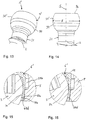
- shows an exploded perspective view of a bone anchoring device according to a first embodiment.
- Fig. 2:
- shows a perspective view of the bone anchoring device of
Fig. 1 in an assembled state. - Fig. 3:
- shows a cross-sectional view of the bone anchoring device of
Figs. 1 and 2 , the cross-section taken in a plane including the central longitudinal axis of the receiving part and extending through a center of the legs of the receiving part. - Fig. 4:
- shows a perspective view from the top of a portion of the bone anchoring element which is part of the bone anchoring device of
Figs. 1 to 3 . - Fig. 5:
- shows a side view of the portion of the bone anchoring element shown in
Fig. 4 . - Fig. 6:
- shows a perspective view from the top of a pressure member of the bone anchoring device according to the first embodiment of
Figs. 1 to 3 . - Fig. 7:
- shows a perspective view from the bottom of the pressure member of
Fig. 6 . - Fig. 8:
- shows a top view of the pressure member of
Figs. 6 and 7 . - Fig. 9a:
- shows a cross-sectional view of the pressure member along line A-A in
Fig. 8 . - Fig. 9b:
- shows an enlarged view of a detail of
Fig. 9a . - Fig. 10:
- shows an enlarged cross-sectional view of a portion of the bone anchoring device in an assembled state as shown in
Fig. 3 with the bone anchoring element assuming an angle with the central axis of the receiving part which is different from the zero angle. - Fig. 11:
- shows an enlarged cross-sectional view of a portion of the bone anchoring device of
Fig. 3 in an assembled state when the bone anchoring element is in a zero angular position. - Fig. 12:
- shows an enlarged cross-sectional view of the bone anchoring device of
Fig. 3 when the bone anchoring element is in an angular position different from the zero angular position. - Fig. 13:
- shows a perspective view of a portion of a bone anchoring element according to a second embodiment of the bone anchoring device.
- Fig. 14:
- shows a side view of the bone anchoring element of
Fig. 13 . - Fig. 15:
- shows an enlarged cross-sectional view of a portion of a second embodiment of the bone anchoring device with the bone anchoring element in a zero angular position.
- Fig. 16:
- shows an enlarged cross-sectional view of the portion of the second embodiment of the bone anchoring device shown in
Fig. 15 with the bone anchoring element in an angular position different from the zero angular position. - Fig. 17:
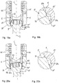
- shows a perspective view of a portion of a bone anchoring element according to a third embodiment of the bone anchoring device.
- Fig. 18a:
- shows a side view of the bone anchoring element of
Fig. 17 . - Fig. 18b:
- shows an enlarged portion of
Fig. 18a . - Fig. 19a:
- shows a cross-sectional view of the polyaxial bone anchoring device according to the third embodiment with the bone anchoring element in a zero angular position, the cross-section taken in a plane including the central longitudinal axis of the receiving part and extending through a center of the legs of the receiving part.
- Fig. 19b:
- shows an enlarged portion of
Fig. 19a . - Fig. 20a:
- shows a cross-sectional view of the polyaxial bone anchoring device of the third embodiment similar to
Fig. 19a with the bone anchoring element at an angular position different from the zero angular position. - Fig. 20b:
- shows an enlarged portion of
Fig. 20a . - A polyaxial bone anchoring device according to a first embodiment which is generally shown in
Figs. 1 to 3 includes abone anchoring element 1 in the form of a screw member having a threadedshank 2 and ahead 3. A shank axis S is defined by the longitudinal axis or screw axis of theshank 2. On its free end 3a, thehead 3 may have a recess 4 for engagement with a tool. The bone anchoring device further includes a receivingpart 5 for connecting the bone anchoring element for an elongate stabilization member, such as arod 100. Apressure member 6 is arranged in the receiving part on top of thehead 3. For securing therod 100 in the receivingpart 5 for exerting pressure onto thepressure member 6, alocking element 7 in the form of, for example, a set screw which cooperates with the receivingpart 5 may be provided in addition. - The receiving
part 5 is substantially cylindrical and has a first or top end 5a, a second or bottom end 5b and apassage 51 extending from the top end 5a towards the bottom end 5b, thepassage 51 defining a longitudinal central axis C. Thepassage 51 forms anopening 52 at the bottom end 5b whichopening 52 has a width that is greater than a greatest width of the head so that thehead 3 ofbone anchoring element 1 is insertable through thebottom end 52. Thepassage 51 may have several sections with different width and/or shape and is not limited to the exact shape shown in the figures. Adjacent to theopening 52, thepassage 51 has anarrowing section 51a which narrows, for example conically, towards the bottom end 5b. Thenarrowing section 51a cooperates with a portion of thepressure member 6 such that a compressive force is exerted via thepressure member 6 onto an insertedhead 3. A widened section 51b follows thenarrowing section 51a in the direction of the top end 5a. The widened section 51b is dimensioned such that a portion of thepressure member 6 can expand therein to permit thehead 3 to enter. Further, thepassage 51 may have an intermediate section 51c that has a smaller width than the widened section 51b and permits a portion of the pressure member to slide therein in an axial direction. Finally, adjacent to the top end 5a and the intermediate section 51c thepassage 51 is formed as a threadedbore 51d with a greater inner diameter than that the intermediate section 51c to permit the insertion of and the cooperation with the lockingelement 7.Threads part 5 and thelocking element 7, respectively, may be threads that reduce or eliminate radial forces during tightening of thelocking element 7, such as a square thread, for example. At the bottom end of theinternal thread 53 anthread runout 53a may be provided. Moreover, as best shown inFigs. 1 and 2 , a substantiallyU-shaped recess 54 is formed at the top end 5a and extends to a distance therefrom. The substantiallyU-shaped recess 54 divides the upper portion of the receivingpart 5 into twofree legs 55 and forms a channel for receiving therod 100. A longitudinal axis of the substantiallyU-shaped recess 54 is coincident with a longitudinal axis of astraight rod 100 when the rod is inserted. - At the center of each
leg 55 in a circumferential direction and at an axial position above a bottom 54a of the substantiallyU-shaped recess 54 through-holes 56 extend through eachleg 55. The through-holes 56 are configured to receivepins 57 as shown inFig. 3 . Thepins 57 may serve for rotationally securing thepressure member 6 in the receivingpart 5. Also, thepins 57 may serve for limiting an upward movement of thepressure member 6 within the receivingpart 5. Furthermore, cut-outs 58 may be formed on either side of thelegs 55 which may contribute to a reduced size of the receivingpart 5. Atool engagement portion 59 such as a circumferential groove and/or central recesses can be optionally provided at thelegs 55 to allow to engage the receivingpart 5 with a tool. - Referring additionally to
Figs. 4 and 5 , thebone anchoring element 1 will be described in more detail. Thehead 3 has the overall shape of a segment of a sphere or, in other words, a truncated sphere which has a size such that it includes a section with a greatest diameter E of the sphere. The segment of the sphere may be arranged in such a manner between a free end 3a of the head and aneck portion 21 of theshank 2 that one end with the smaller outer diameter is close to theneck portion 21 and the other end with the greater outer diameter is closer to the free end 3a than to theneck portion 21. However, the segment of the sphere can also extend at both sides from the section with the greatest diameter E to the same distance or may end at or below the greatest diameter E. Theneck portion 21 may be substantially thread-free. - More specifically, the
head 3 includes at its outer surface a firstcurved portion 31 and a secondcurved portion 32. The firstcurved portion 31 is defined by the spherical segment that forms the overall shape of thehead 3 and has a first radius of curvature R1 defined by the radius of the sphere. Further, the firstcurved portion 31 is located adjacent to or close to theneck portion 21 and includes in the embodiment shown the greatest outer diameter E. The secondcurved portion 32 may be, for example, substantially toroid segment-shaped and has a second radius of curvature R2 that is smaller than the first radius of curvature R1. The secondcurved portion 32 is located between the firstcurved portion 31 and the free end 3a of thehead 3. In a section through the center of thehead 3 and including the shank axis S, the surface of the firstcurved portion 31 and the secondcurved portion 32 form substantially circular arcs. Moreover, the firstcurved portion 31 and the secondcurved portion 32 join each other in such a manner that the outer surface of thehead 3 is substantially continuous at atransition 33. Hence, there is no substantial step at thetransition 33 or in other words, the transition is step-free. The firstcurved portion 31 and the secondcurved portion 32 with theirtransition 33 form a first position indication structure provided on thehead 3. It shall be noted that only a part of the entire firstcurved portion 31 and secondcurved portion 32 in a region around the transition may form the first position indication structure. - An axial length in the direction of the shank axis S of the second
curved portion 32 may be considerably smaller than an axial length of the firstcurved portion 31. For example, the secondcurved portion 32 may only have the typical axial length of a bevelled region. The second curved portion may be manufactured, for example, using a turning tool configured to form a radius at an edge of a work piece. It shall be noted that such a first position indication structure consisting of a transition between a first curvature and a second curvature is relatively easy to manufacture which contributes to efforts to reduce the costs. - The free end portion 3a may be substantially flat. The recess 4 for the tool may have any shape, a polygon shape, a torque-shape or any other shape to provide a form-fit connection to a tool.
- Referring now in addition to
Figs. 6 to 9b thepressure member 6 will be explained more in detail. Thepressure member 6 of this embodiment is a monolithic piece. It has a first ortop end 6a and a second orbottom end 6b. Adjacent to thetop end 6a, there is anupper portion 61 that may be substantially cylindrical and that has an outer diameter which allows it to move in the axial direction in thepassage 51 of the receivingpart 5. At thetop end 6a, arod receiving recess 62 is formed that provides a rod support surface. A lower section of therecess 61 may have a substantially V-shaped cross-section with a longitudinal axis extending substantially perpendicular to the cylinder axis of thepressure member 6 which coincides with the central axis C of the receivingpart 5 when the pressure member is in the receivingpart 5. A depth of therecess 62 may be smaller than a diameter of therod 100. Hence, when therod 100 rests on the support surface, it projects over thetop end 6a of thepressure member 6 as shown, for example inFig. 3 . The V-shape of the rod support surface permits to use rods with different diameters. - A
lower portion 63 of thepressure member 6 comprises a tapered, preferably conical outer surface which is configured to cooperate at itslower region 63a adjacent to thebottom end 6b with thenarrowing section 51a of the receiving part. Ahead receiving recess 64 is formed in thelower portion 63 that extends from thebottom end 6b to a distance from a bottom 62a of therod receiving recess 62. Thehead receiving recess 64 comprises alower section 64a close to thebottom end 6b that has a substantially hollow spherical shape with a radius of the sphere matching that of the firstcurved portion 31 of thehead 3. Furthermore, anuppermost portion 64b of thehead receiving recess 64 is also hollow spherically-shaped with the same radius as thelower portion 64a. by means of this, the lowerspherical section 64a and the upperspherical section 64b provide a spherical support for the firstcurved portion 31 of thehead 3 and thus form a seat in which thehead 3 can pivot. Between these two spherically-shapedsections intermediate section 64c is provided that forms a cut-out and has a greater inner diameter than the lower end of the upperspherical section 64b. More in detail, the intermediate widenedsection 64c widens from the lower end of the upperspherical section 64b for example with a substantially flat step and continues with increasing inner diameter, for example with a conical shape, until it matches the inner diameter of the lower spherical section (Figs, 9a, 9b ). By means of the step andedge 65 is formed. Theedge 65 is preferably rounded As theedge 65 is defined at a border of the spherical portion, the inner surface of thehead receiving recess 64 can be formed substantially free from a separate protrusion that protrudes from the head contacting surface of thespherical portion - In addition, the
lower portion 63 of the pressure member comprisesflexible wall sections 66 that are separated byaxial slots 67 open towards thebottom end 6b. To obtain a certain degree of flexibility, theslots 67 may widen towards theirclosed end 67a. Theslots 67 may extend in the axial direction preferably up to the transition between theintermediate section 64c and the uppermost spherical segment-shapedsection 64b. - A size of the
head receiving recess 64 and the sections formed therein is such that when thehead 3 is inserted, the free end 3a of thehead 3 extends into the upperspherical section 64b. Agap 68 is then formed between the outer surface of thehead 3 and the inner surface of theintermediate section 64c of thehead receiving recess 64. Moreover, the size of thehead 3 and thelower portion 63 of the pressure member including thehead receiving recess 64 is such that the head can be inserted through thebottom end 6b by spreading apart theflexible wall section 66 until the upper portion of thehead 3 abuts against theedge 65. The connection is similar to a snap-fit connection. When thehead 3 is received in thehead receiving recess 64 it is held therein by friction via theflexible wall sections 66 before locking is effected, for example with the lockingelement 7. - The pressure member further includes
elongate recesses 69 that are formed in the sidewalls of therod receiving recess 62. The elongate recesses 69 are oriented with their long side substantially parallel to the central axis C. As shown inFig. 3 , theelongate recesses 69 extend through the entire sidewall and are configured to receive thepins 57. By means of this, when thepressure member 6 is mounted to the receivingpart 5, it can be fixed in its rotational position through thepins 57 that extend into the elongate recesses 69. Furthermore, an upward movement of thepressure member 6 relative to the receiving part towards the first end 5a is limited by an abutment of thepins 57 against the lower end 69a of therecesses 69. - Lastly, the
pressure member 6 has acoaxial bore 60 for allowing access to thehead 3, more particularly to the recess 4 of thebone anchoring element 1 with a tool. - The parts and portions of the bone anchoring device may be made of any material, preferably however of titanium or stainless steel or any bio-compatible metal or metal alloy or plastic material. As bio-compatible alloy, a NiTi alloy, for example Nitinol, may be used. Other materials can be magnesium or magnesium alloys. Bio-compatible plastic materials for use may be, for example, polyether ether ketone (PEEK) or poly-L-lactide acid (PLLA). The parts can be made of the same or of different materials from another.
- In use, the
bone anchoring element 1 may be inserted first into a prepared hole in bone or in a vertebra and the receivingpart 5 with thepre-assembled pressure member 6 is mounted onto thehead 3. Alternatively, the bone anchoring device is pre-assembled in such a manner that the receivingpart 5 with thepressure member 6 is already mounted onto thehead 3. For mounting, thehead 3 is inserted from the lower end 5a of the receiving part while thepressure member 6 is at an uppermost insertion position where thepins 57 abut against the lower end 69a of the elongated recesses 69. Once thehead 3 has been inserted, thepressure member 6 is moved downward until the lower outer taperedportion 63a enters into thenarrowing section 51a of the receivingpart 5 and exerts a compression force onto thehead 3. Also, in this condition, thehead 3 cannot be removed through thelower opening 52. - As long as the bone anchoring device is not yet finally locked by inserting the rod and fixing it with the locking
element 7, the receivingpart 5 and thebone anchoring element 1 can be pivoted relative to each other so that thebone anchoring element 1 can assume various angular positions of the shank axis S with respect to the central axis C of the receiving part. Depending on the strength of the frictional clamping of thehead 3 any position can be maintained provisionally before locking. This is possible without insertion of the rod and thelocking element 7. - A predetermined position in this embodiment may be the position in which the shank axis S and the central axis C of the receiving part coincide as shown in
Figs. 3 and11 . In other words, the bone anchoring element assumes a zero angle position with respect to the receivingpart 5. A position different from the zero angle position is shown inFigs. 10 and 12 . When thebone anchoring element 1 is in an angular position different from the zero angular position, theedge 65 contacts he second curvedportion 32 of thehead 3 at the opposite side of the side to which the shank is pivoted. When thehead 3 is then pivoted relative to the receivingpart 5 towards the zero angular position which is shown inFigs. 3 and11 , theedge 65 moves along the outer surface of thehead 3 from the secondcurved portion 32 with the smaller radius to the firstcurved portion 31 with the greater radius thereby passing the transition. During the movement, the pressure member may be slightly expanded until the firstcurved portion 31 contacts the upperspherical section 64b. The transition from the smaller radius to the greater radius functions in a ramp-like manner and produces a tactile feedback to a user. A user may experience the change in slope until the zero angular position is reached and or is left again by pivoting towards another angular position. As the position indication structure provided by the differently curved sections is rotationally symmetrical, the feedback is generated when pivoting in any direction. - Once a suitable angular position is found, the whole construct is locked by inserting the rod and the
fixation element 7 and tightening thefixation element 7. - Referring now to
Figs. 13 to 16 , a second embodiment of the polyaxial bone anchoring device will be described. The polyaxial bone anchoring device according to the second embodiment differs from the polyaxial bone anchoring device of the first embodiment in the shape of the bone anchoring element and the pressure member. The receiving part is the same as for the first embodiment. Identical or highly similar parts are indicated with the same reference numerals and the description thereof will not be repeated. The bone anchoring element 1' has a head 3' which has a spherical segment-shapedportion 31' that may include a section with the greatest diameter E and that joins theneck 21. The spherically-shaped outer surface is interrupted by aconical portion 34 that tapers towards theneck portion 21. Theconical portion 34 is located closer to theneck portion 21 than to the free end surface 3a. More specifically, theconical portion 34 is located in a lower portion of the head 3', i.e. is sandwiched between the section with the greatest diameter E and the spherically-shaped portion adjoining theneck portion 21. An axial extension of theconical portion 34 may be considerably smaller than the axial extension of the entire spherical segment-shapedportion 31'. The axial length may be as large as there is still enough spherical surface for allowing pivoting. Specifically, it may be, for example, less than a third or even less than a quarter of the axial length of the spherical segment-shapedportion 31'. - The pressure member 6' is identical to the pressure member of the previous embodiment except that it comprises a counterpart conical section for engaging the
conical section 34 of the head 3'. As shown inFigs. 15 and 16 , aconical section 64d is formed within the lowerspherical section 64a of thehead receiving recess 64. Theconical section 64d may have the same cone angle as theconical section 34 of the head 3' and may have the same axial extension. However, the axial extension may also be smaller than that of theconical section 34 of the head 3'. Theconical section 64d extends fully circumferentially in the inner wall of thehead receiving recess 64 and is at such a height that in the zero angle position it matches with theconical portion 34 of the head 3'. - In use, when the head 3' is inserted into the pressure member 6' which is in the receiving
part 5 and the pressure member is moved downward so that the outerconical section 63a of the pressure member and thenarrowing section 51a of the receiving part are engaged to clamp the head, the head is captured in thehead receiving recess 64 such that the spherical segment-shapedportion 31' contacts thespherical sections head receiving recess 64 to allow pivoting of the bone anchoring element. When the bone anchoring element 1' is in the zero angle position as depicted inFig. 15 , theconical sections 34 of thehead 3' and 64d of the pressure member 6' are engaged. By means of this, the zero angle position is automatically centered. When the bone anchoring element is pivoted to an angular position different from the zero angular position as shown inFig. 16 , theconical sections 34 of thehead 3' and 64d of the pressure member are substantially out of engagement. Moving into the zero angle position or out of the zero angle position produces a feedback, preferably a tactile feedback to a user. Hence, the zero angular position can be easily identified. - It shall be noted that the bone anchoring element 1' depicted in
Figs. 13. to 16 is free of the secondcurved portion 32 close to the free end surface 3a which has a smaller radius in the previous embodiment. However, it is conceivable that the bone anchoring element 1' also has the secondcurved portion 32 with a smaller radius as in the first embodiment. - Referring to
Figs. 17 to 20b a third embodiment of the polyaxial bone anchoring device will be described. - The polyaxial bone anchoring device according to the third embodiment differs from the polyaxial bone anchoring device according to the first and second embodiment in the shape of the bone anchoring element, more specifically in the shape of the head of the bone anchoring element. Parts and portions that are identical or highly similar with those of the previous embodiments are indicated with the same reference numerals and the description thereof will not be repeated. The
bone anchoring element 1" comprises ahead 3" which has an overall spherical segment-shapedportion 31" as in the second embodiment. The spherical segment-shapedportion 31" may include the section with the greatest diameter E. At a distance from the free end 3a agroove 35 is formed that extends circumferentially and concentrically around the central axis. Thegroove 35 may have a rounded inner contour, such as a spherical contour. Moreover, thegroove 35 is relatively small and shallow. Specifically, the depths of thegroove 35 may be such that it is sufficient to generate a transition between the spherical outer contour of the spherical segment-shapedportion 31" and thegroove 35. An axial position of the groove is such that thegroove 35 is closer to the free end 3a than to theneck portion 21. It may be, as shown in the figures, at a distance from the free end 3a that is the about same or only slightly greater than a width of the groove in the axial direction. - In use, when the
head 3" is inserted into thehead receiving recess 64 of thepressure member 6 when thepressure member 6 is within the receiving part and moved downward so that the lower outerconical portion 63a of thepressure member 6 engages the narrowingportion 51a of the receiving part to clamp the head, thehead 3" abuts against the upper spherical segment-shapedportion 64b of the pressure member. As shown inFigs. 19a and 19b , when the bone anchoring element is in the zero angular position, theedge 65 is slightly protruding into thegroove 35. hence, thebone anchoring element 1" is slightly held in the zero angle position. When thebone anchoring element 1" is pivoted as shown inFigs. 20a and 20b , theedge 65 is moved out of thegroove 35. This gives a feedback, for example a tactile feedback to a user. Similarly, when theedge 65 moves into thegroove 35, such feedback is generated. The feedback may be a haptic resistance. Hence, when moving into the zero angular position a feedback is given to a user who may easily identify the zero angular position. - It shall be noted that the head may have additionally a conical surface like in the second embodiment and the pressure member have additionally the conical surface as in the second embodiment. Alternatively or in addition, the head may have an additional section with a smaller radius like in the first embodiment.
- Modifications of the embodiments described above are conceivable. The features of one embodiment can be combined with those of other embodiments to provide a variety of further embodiments. The receiving part is not limited to the receiving part of the various embodiments shown. As the interaction is only between the head and the pressure member, all known receiving parts may be used and retrofitted with suitable bone anchoring elements and pressure members that have the first and the second position indication structures. The position indication structures are not limited to indicate only the zero position. They can also be used to indicate a predetermined position in which the shank assumes an angle different from zero with respect to the receiving part. In such a case, the position indication features may be at other locations.
- While the head is shown to be a spherical head and the pressure member is shown to have a spherical head receiving recess, the bone anchoring device is not limited thereto. It is conceivable that the head and the pressure member are shaped so as to permit angulation in one or more distinct planes only.
Claims (15)
- A bone anchoring device, including:an anchoring element (1, 1', 1") having a shank (2) for anchoring in bone and a head (3, 3', 3"),a receiving part (5,) configured to receive the head (3) of the anchoring element in a pivotable manner such that the shank (2) can assume a plurality of angular positions including a predetermined angular position relative to the receiving part, the receiving part having a passage (51) defining a central axis (C),a pressure member (6, 6') configured to exert pressure onto the head (3, 3', 3") to clamp the head in the receiving part, the pressure member being at least partially arranged in the passage,wherein the head (3, 3', 3") comprises an outer surface portion that defines a first position indication structure configured to engage a second position indication structure of the pressure member (6); whereinthe first position indication structure or the second position indication structure includes a transition (33) between a first curved portion (31) defining a first curvature and a second curved portion (32) defining a second curvature different from the first curvature andwherein when the first position indication structure and the second position indication structure mutually engage and the head is pivoted from one of the plurality of angular positions to the the predetermined angular position the transition is passed by the respective other of the second or the first position indication structure to provide an indication of the predetermined angular position of the shank (2) relative to the receiving part (5) .
- The bone anchoring device of claim 1, wherein the first position indication structure includes the transition (33).
- The bone anchoring device of claim 1 or 2, wherein the first curved portion (31) is less curved than the second curved portion (32).
- The bone anchoring device of one of claims 1 to 3, wherein the first curved portion (31) is associated with a first radius (R1) and the second curved portion (32) is associated with a second radius, wherein the first radius is different from the second radius, and wherein preferably the transition (33) between the first curved portion (31) and the second curved portion (32) is continuous.
- The bone anchoring device of one of claims 2 to 4, wherein the second curved portion (32) is located close to or adjacent to a free end (3a) of the head (3).
- The bone anchoring device of one of claims 1 to 5, wherein the first position indication structure includes an edge (65) that is configured to pass the transition (33) between the first curved portion (31) and the second curved portion (32) of the second position indication structure.
- The bone anchoring device of one of claims 2 to 6, wherein the pressure member (6, 6') comprises a head receiving recess (64) that includes an inner surface facing an inserted head (3) which defines the first position indication structure (65) and wherein the inner surface comprises a third curved portion (64a, 64b) matching a curvature of the first curved portion (31).
- The bone anchoring device of one of claims 1 to 7, wherein the head receiving recess (64) is configured to receive the head (3, 3', 3") in a snap-fit manner such that the head is held by friction therein prior to locking.
- The bone anchoring device of one of claims 1 to 8, wherein the first or the second position indication structure further comprises a groove (35).
- The bone anchoring device of one of claims 1 to 9, wherein the first position indication structure further comprises a first flat portion (34) and the second position indication structure further comprises a second flat portion (64d) configured to engage the first flat portion and wherein preferably the first and the second flat portions are conical.
- The bone anchoring device of one of claims 1 to 10, wherein the first and/or the second position indication structure is rotationally symmetrical around a respective axis of symmetry (C, S).
- A bone anchoring device, including:an anchoring element (1) having a shank (2) for anchoring in bone and a head (3'),a receiving part (5,) configured to receive the head (3') of the anchoring element in a pivotable manner such that the shank (2) can assume a plurality of angular positions including a predetermined angular position relative to the receiving part, the receiving part having a passage (51) defining a central axis,a pressure member (6') configured to exert pressure onto the head to clamp the head in the receiving part, the pressure member being at least partially arranged in the passage,wherein the head (3') comprises a substantially spherical segment-shaped portion (31') including an outer surface portion that defines a first position indication structure configured to engage a second position indication structure of the pressure member (6) to provide an indication of the predetermined angular position of the shank (2) relative to the receiving part; whereinthe first position indication structure includes a first conical portion (34) and the second position indication structure comprises a second conical portion (64d) configured to engage the first conical portion when the head (3') is in the predetermined angular position.
- The bone anchoring device of claim 12, wherein the first conical portion (34) is sandwiched between two spherical sections of the substantially spherical segment-shaped portion (31').
- The bone anchoring device of claim 12 or 13, wherein the first conical portion (34) is at a lower side of the head (3') closer to the shank (2) than to a free end (3a) of the head.
- The bone anchoring device of one of claims 1 to 14, wherein the receiving part (5) comprises a first end (5a) and an opposite second end (5b), a recess (54) for receiving a rod (100) at the first end and wherein the passage (51) extends through the first end and the second end forming an opening (52) at the second end, the opening being sized so as to permit insertion of the head t(3, 3', 3") through the second end (5b).
Priority Applications (6)
| Application Number | Priority Date | Filing Date | Title |
|---|---|---|---|
| EP20159292.0A EP3871624B1 (en) | 2020-02-25 | 2020-02-25 | Bone anchoring device |
| JP2021026611A JP7555286B2 (en) | 2020-02-25 | 2021-02-22 | Bone fixation device |
| CN202110197634.0A CN113367784B (en) | 2020-02-25 | 2021-02-22 | Bone anchoring device |
| US17/181,525 US11191571B2 (en) | 2020-02-25 | 2021-02-22 | Bone anchoring device |
| US17/512,992 US12207846B2 (en) | 2020-02-25 | 2021-10-28 | Bone anchoring device |
| US19/001,939 US20250186089A1 (en) | 2020-02-25 | 2024-12-26 | Bone anchoring device |
Applications Claiming Priority (1)
| Application Number | Priority Date | Filing Date | Title |
|---|---|---|---|
| EP20159292.0A EP3871624B1 (en) | 2020-02-25 | 2020-02-25 | Bone anchoring device |
Publications (2)
| Publication Number | Publication Date |
|---|---|
| EP3871624A1 true EP3871624A1 (en) | 2021-09-01 |
| EP3871624B1 EP3871624B1 (en) | 2023-07-19 |
Family
ID=69845816
Family Applications (1)
| Application Number | Title | Priority Date | Filing Date |
|---|---|---|---|
| EP20159292.0A Active EP3871624B1 (en) | 2020-02-25 | 2020-02-25 | Bone anchoring device |
Country Status (4)
| Country | Link |
|---|---|
| US (3) | US11191571B2 (en) |
| EP (1) | EP3871624B1 (en) |
| JP (1) | JP7555286B2 (en) |
| CN (1) | CN113367784B (en) |
Cited By (1)
| Publication number | Priority date | Publication date | Assignee | Title |
|---|---|---|---|---|
| WO2023215480A1 (en) * | 2022-05-04 | 2023-11-09 | Corelink, Llc | Bone screw for attaching rod to bone |
Families Citing this family (5)
| Publication number | Priority date | Publication date | Assignee | Title |
|---|---|---|---|---|
| US7901437B2 (en) * | 2007-01-26 | 2011-03-08 | Jackson Roger P | Dynamic stabilization member with molded connection |
| EP3871624B1 (en) * | 2020-02-25 | 2023-07-19 | Biedermann Technologies GmbH & Co. KG | Bone anchoring device |
| WO2022184797A1 (en) | 2021-03-05 | 2022-09-09 | Medos International Sarl | Selectively locking polyaxial screw |
| US20250339183A1 (en) * | 2022-09-01 | 2025-11-06 | GetSet Surgical SA | Bone securing systems and methods |
| EP4686453A1 (en) * | 2024-08-01 | 2026-02-04 | Biedermann Technologies GmbH & Co. KG | Receiving part of a bone anchoring device and system of at least one instrument and a receiving part |
Citations (2)
| Publication number | Priority date | Publication date | Assignee | Title |
|---|---|---|---|---|
| US20160278832A1 (en) * | 2015-03-25 | 2016-09-29 | Robert Reid, Inc. | Spine fixation device and spine fixation system |
| US9833263B2 (en) | 2015-04-13 | 2017-12-05 | Medos International Sarl | Bone anchor assemblies with orientation indicator |
Family Cites Families (50)
| Publication number | Priority date | Publication date | Assignee | Title |
|---|---|---|---|---|
| US6248105B1 (en) | 1997-05-17 | 2001-06-19 | Synthes (U.S.A.) | Device for connecting a longitudinal support with a pedicle screw |
| DE19720782B4 (en) | 1997-05-17 | 2004-12-09 | Synthes Ag Chur, Chur | Device for connecting a side member to a pedicle screw |
| US6113601A (en) | 1998-06-12 | 2000-09-05 | Bones Consulting, Llc | Polyaxial pedicle screw having a loosely coupled locking cap |
| FR2796545B1 (en) | 1999-07-22 | 2002-03-15 | Dimso Sa | POLY-AXIAL LINK FOR OSTEOSYNTHESIS SYSTEM, ESPECIALLY FOR THE RACHIS |
| US7001389B1 (en) | 2002-07-05 | 2006-02-21 | Navarro Richard R | Fixed and variable locking fixation assembly |
| US7087057B2 (en) | 2003-06-27 | 2006-08-08 | Depuy Acromed, Inc. | Polyaxial bone screw |
| AU2005299617B2 (en) | 2004-10-25 | 2010-10-28 | X-Spine Systems, Inc. | Pedicle screw systems and methods |
| US8353939B2 (en) | 2005-01-12 | 2013-01-15 | Warsaw Orthopedic, Inc. | Anchor retaining mechanisms for bone plates |
| US7445627B2 (en) | 2005-01-31 | 2008-11-04 | Alpinespine, Llc | Polyaxial pedicle screw assembly |
| US10076361B2 (en) | 2005-02-22 | 2018-09-18 | Roger P. Jackson | Polyaxial bone screw with spherical capture, compression and alignment and retention structures |
| WO2008024937A2 (en) * | 2006-08-23 | 2008-02-28 | Pioneer Surgical Technology, Inc. | Minimally invasive surgical system |
| DE602005016791D1 (en) | 2005-07-08 | 2009-11-05 | Biedermann Motech Gmbh | Bone anchoring device |
| US20070118117A1 (en) | 2005-10-20 | 2007-05-24 | Ebi, L.P. | Bone fixation assembly |
| US8097025B2 (en) * | 2005-10-25 | 2012-01-17 | X-Spine Systems, Inc. | Pedicle screw system configured to receive a straight or curved rod |
| US8057519B2 (en) | 2006-01-27 | 2011-11-15 | Warsaw Orthopedic, Inc. | Multi-axial screw assembly |
| US20080015597A1 (en) | 2006-04-28 | 2008-01-17 | Whipple Dale E | Large diameter bone anchor assembly |
| US7806913B2 (en) | 2006-08-16 | 2010-10-05 | Depuy Spine, Inc. | Modular multi-level spine stabilization system and method |
| US7867258B2 (en) | 2006-10-17 | 2011-01-11 | Warsaw Orthopedic, Inc. | Multi-axial bone attachment member |
| DE602006009682D1 (en) | 2006-11-17 | 2009-11-19 | Biedermann Motech Gmbh | Bone anchoring device |
| WO2008118295A2 (en) | 2007-03-26 | 2008-10-02 | Laszlo Garamszegi | Bottom-loading pedicle screw assembly |
| KR20110008033A (en) | 2008-04-22 | 2011-01-25 | 신세스 게엠바하 | Bone fixation element with conquest tab |
| US8157846B2 (en) | 2008-07-24 | 2012-04-17 | Ingenium S.A. | Locking mechanism with two-piece washer |
| EP2160988B1 (en) | 2008-09-04 | 2012-12-26 | Biedermann Technologies GmbH & Co. KG | Rod-shaped implant in particular for stabilizing the spinal column and stabilization device including such a rod-shaped implant |
| ES2375879T3 (en) | 2008-12-23 | 2012-03-07 | Biedermann Motech Gmbh | RECEPTION AREA OF A ROD FOR COUPLING THE ROD IN AN BONE ANCHORAGE ELEMENT AND BONE ANCHORAGE DEVICE WITH SUCH RECEPTION AREA. |
| EP2201903B1 (en) * | 2008-12-29 | 2013-05-01 | Biedermann Technologies GmbH & Co. KG | Receiving part for receiving a rod for coupling the rod to a bone anchoring element and bone anchoring device with such a receiving part |
| ES2548580T3 (en) | 2009-02-20 | 2015-10-19 | Biedermann Technologies Gmbh & Co. Kg | Receiving part for housing a rod for coupling to a bone anchoring element and bone anchoring device that includes such receiving part |
| US8241341B2 (en) * | 2009-03-20 | 2012-08-14 | Spinal Usa, Inc. | Pedicle screws and methods of using the same |
| EP2485654B1 (en) | 2009-10-05 | 2021-05-05 | Jackson P. Roger | Polyaxial bone anchor with non-pivotable retainer and pop-on shank, some with friction fit |
| US8361123B2 (en) | 2009-10-16 | 2013-01-29 | Depuy Spine, Inc. | Bone anchor assemblies and methods of manufacturing and use thereof |
| EP2611373B1 (en) | 2010-08-30 | 2015-11-04 | Zimmer Spine, Inc. | Polyaxial pedicle screw |
| GB2507620A (en) * | 2010-11-02 | 2014-05-07 | Roger P Jackson | Polyaxial bone anchor with pop-on shank and pivotable retainer |
| ES2461843T3 (en) | 2010-12-23 | 2014-05-21 | Biedermann Technologies Gmbh & Co. Kg | Bone anchoring device |
| US11076887B2 (en) * | 2011-07-15 | 2021-08-03 | Globus Medical, Inc. | Orthopedic fixation devices and methods of installation thereof |
| US8888827B2 (en) * | 2011-07-15 | 2014-11-18 | Globus Medical, Inc. | Orthopedic fixation devices and methods of installation thereof |
| EP2918237A1 (en) * | 2011-09-15 | 2015-09-16 | Biedermann Technologies GmbH & Co. KG | Polyaxial bone anchoring device with enlarged pivot angle |
| EP2606841B1 (en) | 2011-12-23 | 2016-03-09 | Biedermann Technologies GmbH & Co. KG | Polyaxial bone anchoring device |
| EP2740424B1 (en) * | 2012-12-10 | 2015-10-14 | Biedermann Technologies GmbH & Co. KG | Anchoring member suitable for use in a polyaxial bone anchoring device and polyaxial bone anchoring device with an enlarged pivot angle to one side |
| US20150012042A1 (en) * | 2013-07-04 | 2015-01-08 | Institute for Musculoskeletal Science and Education, Ltd. | Orthopedic implantation device |
| US10028770B2 (en) * | 2014-10-20 | 2018-07-24 | Warsaw Orthopedic, Inc. | Spinal implant system and methods of use |
| US9956003B2 (en) * | 2015-09-18 | 2018-05-01 | Warsaw Orthopedic, Inc | Spinal implant system and methods of use |
| EP3473198B1 (en) * | 2016-08-04 | 2023-02-22 | Biedermann Technologies GmbH & Co. KG | Polyaxial bone anchoring device and system of an instrument and a polyaxial bone anchoring device |
| EP3476340B1 (en) * | 2017-10-25 | 2021-06-02 | Biedermann Technologies GmbH & Co. KG | Polyaxial bone anchoring device |
| US10695100B2 (en) * | 2017-12-15 | 2020-06-30 | Warsaw Orthopedic, Inc. | Spinal implant system and methods of use |
| EP3708097B1 (en) * | 2017-12-22 | 2023-06-14 | Biedermann Technologies GmbH & Co. KG | Polyaxial bone anchoring device and system of an instrument and a polyaxial bone anchoring device |
| US11241259B2 (en) * | 2018-08-30 | 2022-02-08 | Zimmer Biomet Spine, Inc. | Bone anchor |
| US11219472B2 (en) * | 2019-01-28 | 2022-01-11 | Nexxt Spine. LLC | Poly-axial implant fixation system |
| US10864090B2 (en) * | 2019-04-23 | 2020-12-15 | Warsaw Orthopedic, Inc. | Spinal implant system and methods of use |
| EP3766443B1 (en) | 2019-07-18 | 2023-02-15 | Biedermann Technologies GmbH & Co. KG | Bone anchoring device |
| EP3785649B1 (en) * | 2019-08-30 | 2022-08-03 | Biedermann Technologies GmbH & Co. KG | Bone anchoring device |
| EP3871624B1 (en) * | 2020-02-25 | 2023-07-19 | Biedermann Technologies GmbH & Co. KG | Bone anchoring device |
-
2020
- 2020-02-25 EP EP20159292.0A patent/EP3871624B1/en active Active
-
2021
- 2021-02-22 CN CN202110197634.0A patent/CN113367784B/en active Active
- 2021-02-22 JP JP2021026611A patent/JP7555286B2/en active Active
- 2021-02-22 US US17/181,525 patent/US11191571B2/en active Active
- 2021-10-28 US US17/512,992 patent/US12207846B2/en active Active
-
2024
- 2024-12-26 US US19/001,939 patent/US20250186089A1/en active Pending
Patent Citations (2)
| Publication number | Priority date | Publication date | Assignee | Title |
|---|---|---|---|---|
| US20160278832A1 (en) * | 2015-03-25 | 2016-09-29 | Robert Reid, Inc. | Spine fixation device and spine fixation system |
| US9833263B2 (en) | 2015-04-13 | 2017-12-05 | Medos International Sarl | Bone anchor assemblies with orientation indicator |
Cited By (1)
| Publication number | Priority date | Publication date | Assignee | Title |
|---|---|---|---|---|
| WO2023215480A1 (en) * | 2022-05-04 | 2023-11-09 | Corelink, Llc | Bone screw for attaching rod to bone |
Also Published As
| Publication number | Publication date |
|---|---|
| JP2021133251A (en) | 2021-09-13 |
| EP3871624B1 (en) | 2023-07-19 |
| US20220117633A1 (en) | 2022-04-21 |
| US20210259742A1 (en) | 2021-08-26 |
| CN113367784A (en) | 2021-09-10 |
| US12207846B2 (en) | 2025-01-28 |
| US11191571B2 (en) | 2021-12-07 |
| US20250186089A1 (en) | 2025-06-12 |
| CN113367784B (en) | 2024-12-13 |
| JP7555286B2 (en) | 2024-09-24 |
Similar Documents
| Publication | Publication Date | Title |
|---|---|---|
| EP3871624B1 (en) | Bone anchoring device | |
| EP3878386B1 (en) | Coupling device for use with a bone anchoring element and bone anchoring device with such a coupling device | |
| EP2283786B1 (en) | A receiving part for receiving a rod for coupling the rod to a bone anchoring element | |
| EP3766443B1 (en) | Bone anchoring device | |
| JP6099919B2 (en) | Bone fixation device and tool | |
| EP2591740A1 (en) | Polyaxial bone anchoring device | |
| US12089878B2 (en) | Bone anchoring device | |
| EP3473198B1 (en) | Polyaxial bone anchoring device and system of an instrument and a polyaxial bone anchoring device | |
| KR20140014006A (en) | Polyaxial bone anchoring device with enlarged pivot angle | |
| US20260114906A1 (en) | Polyaxial bone anchoring device | |
| US20250359898A1 (en) | Coupling device for coupling a rod to a bone anchor and system including such a coupling device and at least two bone anchors | |
| US20250288329A1 (en) | Coupling device for coupling a rod to a bone anchor | |
| CN122056636A (en) | Connection device for connecting the rod to the bone anchoring element. |
Legal Events
| Date | Code | Title | Description |
|---|---|---|---|
| PUAI | Public reference made under article 153(3) epc to a published international application that has entered the european phase |
Free format text: ORIGINAL CODE: 0009012 |
|
| STAA | Information on the status of an ep patent application or granted ep patent |
Free format text: STATUS: REQUEST FOR EXAMINATION WAS MADE |
|
| 17P | Request for examination filed |
Effective date: 20201123 |
|
| AK | Designated contracting states |
Kind code of ref document: A1 Designated state(s): AL AT BE BG CH CY CZ DE DK EE ES FI FR GB GR HR HU IE IS IT LI LT LU LV MC MK MT NL NO PL PT RO RS SE SI SK SM TR |
|
| GRAP | Despatch of communication of intention to grant a patent |
Free format text: ORIGINAL CODE: EPIDOSNIGR1 |
|
| STAA | Information on the status of an ep patent application or granted ep patent |
Free format text: STATUS: GRANT OF PATENT IS INTENDED |
|
| INTG | Intention to grant announced |
Effective date: 20220316 |
|
| GRAJ | Information related to disapproval of communication of intention to grant by the applicant or resumption of examination proceedings by the epo deleted |
Free format text: ORIGINAL CODE: EPIDOSDIGR1 |
|
| STAA | Information on the status of an ep patent application or granted ep patent |
Free format text: STATUS: REQUEST FOR EXAMINATION WAS MADE |
|
| INTC | Intention to grant announced (deleted) | ||
| GRAP | Despatch of communication of intention to grant a patent |
Free format text: ORIGINAL CODE: EPIDOSNIGR1 |
|
| STAA | Information on the status of an ep patent application or granted ep patent |
Free format text: STATUS: GRANT OF PATENT IS INTENDED |
|
| INTG | Intention to grant announced |
Effective date: 20220921 |
|
| GRAJ | Information related to disapproval of communication of intention to grant by the applicant or resumption of examination proceedings by the epo deleted |
Free format text: ORIGINAL CODE: EPIDOSDIGR1 |
|
| STAA | Information on the status of an ep patent application or granted ep patent |
Free format text: STATUS: REQUEST FOR EXAMINATION WAS MADE |
|
| GRAP | Despatch of communication of intention to grant a patent |
Free format text: ORIGINAL CODE: EPIDOSNIGR1 |
|
| STAA | Information on the status of an ep patent application or granted ep patent |
Free format text: STATUS: GRANT OF PATENT IS INTENDED |
|
| INTC | Intention to grant announced (deleted) | ||
| INTG | Intention to grant announced |
Effective date: 20230203 |
|
| GRAS | Grant fee paid |
Free format text: ORIGINAL CODE: EPIDOSNIGR3 |
|
| GRAA | (expected) grant |
Free format text: ORIGINAL CODE: 0009210 |
|
| STAA | Information on the status of an ep patent application or granted ep patent |
Free format text: STATUS: THE PATENT HAS BEEN GRANTED |
|
| AK | Designated contracting states |
Kind code of ref document: B1 Designated state(s): AL AT BE BG CH CY CZ DE DK EE ES FI FR GB GR HR HU IE IS IT LI LT LU LV MC MK MT NL NO PL PT RO RS SE SI SK SM TR |
|
| REG | Reference to a national code |
Ref country code: GB Ref legal event code: FG4D |
|
| REG | Reference to a national code |
Ref country code: CH Ref legal event code: EP |
|
| REG | Reference to a national code |
Ref country code: DE Ref legal event code: R096 Ref document number: 602020013911 Country of ref document: DE |
|
| P01 | Opt-out of the competence of the unified patent court (upc) registered |
Effective date: 20230630 |
|
| REG | Reference to a national code |
Ref country code: IE Ref legal event code: FG4D |
|
| REG | Reference to a national code |
Ref country code: LT Ref legal event code: MG9D |
|
| REG | Reference to a national code |
Ref country code: NL Ref legal event code: MP Effective date: 20230719 |
|
| REG | Reference to a national code |
Ref country code: AT Ref legal event code: MK05 Ref document number: 1588694 Country of ref document: AT Kind code of ref document: T Effective date: 20230719 |
|
| PG25 | Lapsed in a contracting state [announced via postgrant information from national office to epo] |
Ref country code: NL Free format text: LAPSE BECAUSE OF FAILURE TO SUBMIT A TRANSLATION OF THE DESCRIPTION OR TO PAY THE FEE WITHIN THE PRESCRIBED TIME-LIMIT Effective date: 20230719 |
|
| PG25 | Lapsed in a contracting state [announced via postgrant information from national office to epo] |
Ref country code: GR Free format text: LAPSE BECAUSE OF FAILURE TO SUBMIT A TRANSLATION OF THE DESCRIPTION OR TO PAY THE FEE WITHIN THE PRESCRIBED TIME-LIMIT Effective date: 20231020 |
|
| PG25 | Lapsed in a contracting state [announced via postgrant information from national office to epo] |
Ref country code: IS Free format text: LAPSE BECAUSE OF FAILURE TO SUBMIT A TRANSLATION OF THE DESCRIPTION OR TO PAY THE FEE WITHIN THE PRESCRIBED TIME-LIMIT Effective date: 20231119 |
|
| PG25 | Lapsed in a contracting state [announced via postgrant information from national office to epo] |
Ref country code: SE Free format text: LAPSE BECAUSE OF FAILURE TO SUBMIT A TRANSLATION OF THE DESCRIPTION OR TO PAY THE FEE WITHIN THE PRESCRIBED TIME-LIMIT Effective date: 20230719 Ref country code: RS Free format text: LAPSE BECAUSE OF FAILURE TO SUBMIT A TRANSLATION OF THE DESCRIPTION OR TO PAY THE FEE WITHIN THE PRESCRIBED TIME-LIMIT Effective date: 20230719 Ref country code: PT Free format text: LAPSE BECAUSE OF FAILURE TO SUBMIT A TRANSLATION OF THE DESCRIPTION OR TO PAY THE FEE WITHIN THE PRESCRIBED TIME-LIMIT Effective date: 20231120 Ref country code: NO Free format text: LAPSE BECAUSE OF FAILURE TO SUBMIT A TRANSLATION OF THE DESCRIPTION OR TO PAY THE FEE WITHIN THE PRESCRIBED TIME-LIMIT Effective date: 20231019 Ref country code: LV Free format text: LAPSE BECAUSE OF FAILURE TO SUBMIT A TRANSLATION OF THE DESCRIPTION OR TO PAY THE FEE WITHIN THE PRESCRIBED TIME-LIMIT Effective date: 20230719 Ref country code: LT Free format text: LAPSE BECAUSE OF FAILURE TO SUBMIT A TRANSLATION OF THE DESCRIPTION OR TO PAY THE FEE WITHIN THE PRESCRIBED TIME-LIMIT Effective date: 20230719 Ref country code: IS Free format text: LAPSE BECAUSE OF FAILURE TO SUBMIT A TRANSLATION OF THE DESCRIPTION OR TO PAY THE FEE WITHIN THE PRESCRIBED TIME-LIMIT Effective date: 20231119 Ref country code: HR Free format text: LAPSE BECAUSE OF FAILURE TO SUBMIT A TRANSLATION OF THE DESCRIPTION OR TO PAY THE FEE WITHIN THE PRESCRIBED TIME-LIMIT Effective date: 20230719 Ref country code: GR Free format text: LAPSE BECAUSE OF FAILURE TO SUBMIT A TRANSLATION OF THE DESCRIPTION OR TO PAY THE FEE WITHIN THE PRESCRIBED TIME-LIMIT Effective date: 20231020 Ref country code: FI Free format text: LAPSE BECAUSE OF FAILURE TO SUBMIT A TRANSLATION OF THE DESCRIPTION OR TO PAY THE FEE WITHIN THE PRESCRIBED TIME-LIMIT Effective date: 20230719 Ref country code: AT Free format text: LAPSE BECAUSE OF FAILURE TO SUBMIT A TRANSLATION OF THE DESCRIPTION OR TO PAY THE FEE WITHIN THE PRESCRIBED TIME-LIMIT Effective date: 20230719 |
|
| PG25 | Lapsed in a contracting state [announced via postgrant information from national office to epo] |
Ref country code: PL Free format text: LAPSE BECAUSE OF FAILURE TO SUBMIT A TRANSLATION OF THE DESCRIPTION OR TO PAY THE FEE WITHIN THE PRESCRIBED TIME-LIMIT Effective date: 20230719 |
|
| REG | Reference to a national code |
Ref country code: DE Ref legal event code: R097 Ref document number: 602020013911 Country of ref document: DE |
|
| PG25 | Lapsed in a contracting state [announced via postgrant information from national office to epo] |
Ref country code: ES Free format text: LAPSE BECAUSE OF FAILURE TO SUBMIT A TRANSLATION OF THE DESCRIPTION OR TO PAY THE FEE WITHIN THE PRESCRIBED TIME-LIMIT Effective date: 20230719 |
|
| PG25 | Lapsed in a contracting state [announced via postgrant information from national office to epo] |
Ref country code: SM Free format text: LAPSE BECAUSE OF FAILURE TO SUBMIT A TRANSLATION OF THE DESCRIPTION OR TO PAY THE FEE WITHIN THE PRESCRIBED TIME-LIMIT Effective date: 20230719 Ref country code: RO Free format text: LAPSE BECAUSE OF FAILURE TO SUBMIT A TRANSLATION OF THE DESCRIPTION OR TO PAY THE FEE WITHIN THE PRESCRIBED TIME-LIMIT Effective date: 20230719 Ref country code: ES Free format text: LAPSE BECAUSE OF FAILURE TO SUBMIT A TRANSLATION OF THE DESCRIPTION OR TO PAY THE FEE WITHIN THE PRESCRIBED TIME-LIMIT Effective date: 20230719 Ref country code: EE Free format text: LAPSE BECAUSE OF FAILURE TO SUBMIT A TRANSLATION OF THE DESCRIPTION OR TO PAY THE FEE WITHIN THE PRESCRIBED TIME-LIMIT Effective date: 20230719 Ref country code: DK Free format text: LAPSE BECAUSE OF FAILURE TO SUBMIT A TRANSLATION OF THE DESCRIPTION OR TO PAY THE FEE WITHIN THE PRESCRIBED TIME-LIMIT Effective date: 20230719 Ref country code: CZ Free format text: LAPSE BECAUSE OF FAILURE TO SUBMIT A TRANSLATION OF THE DESCRIPTION OR TO PAY THE FEE WITHIN THE PRESCRIBED TIME-LIMIT Effective date: 20230719 Ref country code: SK Free format text: LAPSE BECAUSE OF FAILURE TO SUBMIT A TRANSLATION OF THE DESCRIPTION OR TO PAY THE FEE WITHIN THE PRESCRIBED TIME-LIMIT Effective date: 20230719 |
|
| PLBE | No opposition filed within time limit |
Free format text: ORIGINAL CODE: 0009261 |
|
| STAA | Information on the status of an ep patent application or granted ep patent |
Free format text: STATUS: NO OPPOSITION FILED WITHIN TIME LIMIT |
|
| PG25 | Lapsed in a contracting state [announced via postgrant information from national office to epo] |
Ref country code: IT Free format text: LAPSE BECAUSE OF FAILURE TO SUBMIT A TRANSLATION OF THE DESCRIPTION OR TO PAY THE FEE WITHIN THE PRESCRIBED TIME-LIMIT Effective date: 20230719 |
|
| 26N | No opposition filed |
Effective date: 20240422 |
|
| PG25 | Lapsed in a contracting state [announced via postgrant information from national office to epo] |
Ref country code: SI Free format text: LAPSE BECAUSE OF FAILURE TO SUBMIT A TRANSLATION OF THE DESCRIPTION OR TO PAY THE FEE WITHIN THE PRESCRIBED TIME-LIMIT Effective date: 20230719 |
|
| PG25 | Lapsed in a contracting state [announced via postgrant information from national office to epo] |
Ref country code: MC Free format text: LAPSE BECAUSE OF FAILURE TO SUBMIT A TRANSLATION OF THE DESCRIPTION OR TO PAY THE FEE WITHIN THE PRESCRIBED TIME-LIMIT Effective date: 20230719 |
|
| PG25 | Lapsed in a contracting state [announced via postgrant information from national office to epo] |
Ref country code: LU Free format text: LAPSE BECAUSE OF NON-PAYMENT OF DUE FEES Effective date: 20240225 |
|
| PG25 | Lapsed in a contracting state [announced via postgrant information from national office to epo] |
Ref country code: LU Free format text: LAPSE BECAUSE OF NON-PAYMENT OF DUE FEES Effective date: 20240225 |
|
| PG25 | Lapsed in a contracting state [announced via postgrant information from national office to epo] |
Ref country code: BG Free format text: LAPSE BECAUSE OF FAILURE TO SUBMIT A TRANSLATION OF THE DESCRIPTION OR TO PAY THE FEE WITHIN THE PRESCRIBED TIME-LIMIT Effective date: 20230719 |
|
| PG25 | Lapsed in a contracting state [announced via postgrant information from national office to epo] |
Ref country code: BG Free format text: LAPSE BECAUSE OF FAILURE TO SUBMIT A TRANSLATION OF THE DESCRIPTION OR TO PAY THE FEE WITHIN THE PRESCRIBED TIME-LIMIT Effective date: 20230719 |
|
| REG | Reference to a national code |
Ref country code: BE Ref legal event code: MM Effective date: 20240229 |
|
| PG25 | Lapsed in a contracting state [announced via postgrant information from national office to epo] |
Ref country code: BE Free format text: LAPSE BECAUSE OF NON-PAYMENT OF DUE FEES Effective date: 20240229 |
|
| PG25 | Lapsed in a contracting state [announced via postgrant information from national office to epo] |
Ref country code: FR Free format text: LAPSE BECAUSE OF NON-PAYMENT OF DUE FEES Effective date: 20240229 |
|
| PG25 | Lapsed in a contracting state [announced via postgrant information from national office to epo] |
Ref country code: IE Free format text: LAPSE BECAUSE OF NON-PAYMENT OF DUE FEES Effective date: 20240225 |
|
| PG25 | Lapsed in a contracting state [announced via postgrant information from national office to epo] |
Ref country code: IE Free format text: LAPSE BECAUSE OF NON-PAYMENT OF DUE FEES Effective date: 20240225 Ref country code: FR Free format text: LAPSE BECAUSE OF NON-PAYMENT OF DUE FEES Effective date: 20240229 Ref country code: BE Free format text: LAPSE BECAUSE OF NON-PAYMENT OF DUE FEES Effective date: 20240229 |
|
| PG25 | Lapsed in a contracting state [announced via postgrant information from national office to epo] |
Ref country code: CY Free format text: LAPSE BECAUSE OF FAILURE TO SUBMIT A TRANSLATION OF THE DESCRIPTION OR TO PAY THE FEE WITHIN THE PRESCRIBED TIME-LIMIT; INVALID AB INITIO Effective date: 20200225 |
|
| PG25 | Lapsed in a contracting state [announced via postgrant information from national office to epo] |
Ref country code: HU Free format text: LAPSE BECAUSE OF FAILURE TO SUBMIT A TRANSLATION OF THE DESCRIPTION OR TO PAY THE FEE WITHIN THE PRESCRIBED TIME-LIMIT; INVALID AB INITIO Effective date: 20200225 |
|
| PG25 | Lapsed in a contracting state [announced via postgrant information from national office to epo] |
Ref country code: TR Free format text: LAPSE BECAUSE OF FAILURE TO SUBMIT A TRANSLATION OF THE DESCRIPTION OR TO PAY THE FEE WITHIN THE PRESCRIBED TIME-LIMIT Effective date: 20230719 |
|
| REG | Reference to a national code |
Ref country code: CH Ref legal event code: U11 Free format text: ST27 STATUS EVENT CODE: U-0-0-U10-U11 (AS PROVIDED BY THE NATIONAL OFFICE) Effective date: 20260301 |
|
| PGFP | Annual fee paid to national office [announced via postgrant information from national office to epo] |
Ref country code: GB Payment date: 20260213 Year of fee payment: 7 |
|
| PGFP | Annual fee paid to national office [announced via postgrant information from national office to epo] |
Ref country code: DE Payment date: 20260224 Year of fee payment: 7 |
|
| PGFP | Annual fee paid to national office [announced via postgrant information from national office to epo] |
Ref country code: CH Payment date: 20260301 Year of fee payment: 7 |