EP3871619A1 - Adjustable blockage-cutting device - Google Patents
Adjustable blockage-cutting device Download PDFInfo
- Publication number
- EP3871619A1 EP3871619A1 EP21158703.5A EP21158703A EP3871619A1 EP 3871619 A1 EP3871619 A1 EP 3871619A1 EP 21158703 A EP21158703 A EP 21158703A EP 3871619 A1 EP3871619 A1 EP 3871619A1
- Authority
- EP
- European Patent Office
- Prior art keywords
- inner tube
- outer tube
- tube
- blockage
- catheter system
- Prior art date
- Legal status (The legal status is an assumption and is not a legal conclusion. Google has not performed a legal analysis and makes no representation as to the accuracy of the status listed.)
- Granted
Links
Images


Classifications
-
- A—HUMAN NECESSITIES
- A61—MEDICAL OR VETERINARY SCIENCE; HYGIENE
- A61B—DIAGNOSIS; SURGERY; IDENTIFICATION
- A61B17/00—Surgical instruments, devices or methods
- A61B17/32—Surgical cutting instruments
- A61B17/3205—Excision instruments
- A61B17/3207—Atherectomy devices working by cutting or abrading; Similar devices specially adapted for non-vascular obstructions
- A61B17/320725—Atherectomy devices working by cutting or abrading; Similar devices specially adapted for non-vascular obstructions with radially expandable cutting or abrading elements
-
- A—HUMAN NECESSITIES
- A61—MEDICAL OR VETERINARY SCIENCE; HYGIENE
- A61B—DIAGNOSIS; SURGERY; IDENTIFICATION
- A61B17/00—Surgical instruments, devices or methods
- A61B17/32—Surgical cutting instruments
- A61B17/3205—Excision instruments
- A61B17/3207—Atherectomy devices working by cutting or abrading; Similar devices specially adapted for non-vascular obstructions
- A61B17/32075—Pullback cutting; combined forward and pullback cutting, e.g. with cutters at both sides of the plaque
-
- A—HUMAN NECESSITIES
- A61—MEDICAL OR VETERINARY SCIENCE; HYGIENE
- A61M—DEVICES FOR INTRODUCING MEDIA INTO, OR ONTO, THE BODY; DEVICES FOR TRANSDUCING BODY MEDIA OR FOR TAKING MEDIA FROM THE BODY; DEVICES FOR PRODUCING OR ENDING SLEEP OR STUPOR
- A61M25/00—Catheters; Hollow probes
- A61M25/10—Balloon catheters
- A61M25/104—Balloon catheters used for angioplasty
-
- A—HUMAN NECESSITIES
- A61—MEDICAL OR VETERINARY SCIENCE; HYGIENE
- A61B—DIAGNOSIS; SURGERY; IDENTIFICATION
- A61B17/00—Surgical instruments, devices or methods
- A61B2017/00535—Surgical instruments, devices or methods pneumatically or hydraulically operated
- A61B2017/00557—Surgical instruments, devices or methods pneumatically or hydraulically operated inflatable
-
- A—HUMAN NECESSITIES
- A61—MEDICAL OR VETERINARY SCIENCE; HYGIENE
- A61B—DIAGNOSIS; SURGERY; IDENTIFICATION
- A61B17/00—Surgical instruments, devices or methods
- A61B17/22—Implements for squeezing-off ulcers or the like on inner organs of the body; Implements for scraping-out cavities of body organs, e.g. bones; for invasive removal or destruction of calculus using mechanical vibrations; for removing obstructions in blood vessels, not otherwise provided for
- A61B2017/22051—Implements for squeezing-off ulcers or the like on inner organs of the body; Implements for scraping-out cavities of body organs, e.g. bones; for invasive removal or destruction of calculus using mechanical vibrations; for removing obstructions in blood vessels, not otherwise provided for with an inflatable part, e.g. balloon, for positioning, blocking, or immobilisation
- A61B2017/22061—Implements for squeezing-off ulcers or the like on inner organs of the body; Implements for scraping-out cavities of body organs, e.g. bones; for invasive removal or destruction of calculus using mechanical vibrations; for removing obstructions in blood vessels, not otherwise provided for with an inflatable part, e.g. balloon, for positioning, blocking, or immobilisation for spreading elements apart
-
- A—HUMAN NECESSITIES
- A61—MEDICAL OR VETERINARY SCIENCE; HYGIENE
- A61B—DIAGNOSIS; SURGERY; IDENTIFICATION
- A61B17/00—Surgical instruments, devices or methods
- A61B17/32—Surgical cutting instruments
- A61B17/3205—Excision instruments
- A61B17/3207—Atherectomy devices working by cutting or abrading; Similar devices specially adapted for non-vascular obstructions
- A61B2017/320741—Atherectomy devices working by cutting or abrading; Similar devices specially adapted for non-vascular obstructions for stripping the intima or the internal plaque from a blood vessel, e.g. for endarterectomy
-
- A—HUMAN NECESSITIES
- A61—MEDICAL OR VETERINARY SCIENCE; HYGIENE
- A61M—DEVICES FOR INTRODUCING MEDIA INTO, OR ONTO, THE BODY; DEVICES FOR TRANSDUCING BODY MEDIA OR FOR TAKING MEDIA FROM THE BODY; DEVICES FOR PRODUCING OR ENDING SLEEP OR STUPOR
- A61M25/00—Catheters; Hollow probes
- A61M25/0021—Catheters; Hollow probes characterised by the form of the tubing
- A61M25/0023—Catheters; Hollow probes characterised by the form of the tubing by the form of the lumen, e.g. cross-section, variable diameter
- A61M2025/0024—Expandable catheters or sheaths
-
- A—HUMAN NECESSITIES
- A61—MEDICAL OR VETERINARY SCIENCE; HYGIENE
- A61M—DEVICES FOR INTRODUCING MEDIA INTO, OR ONTO, THE BODY; DEVICES FOR TRANSDUCING BODY MEDIA OR FOR TAKING MEDIA FROM THE BODY; DEVICES FOR PRODUCING OR ENDING SLEEP OR STUPOR
- A61M25/00—Catheters; Hollow probes
- A61M25/01—Introducing, guiding, advancing, emplacing or holding catheters
- A61M25/02—Holding devices, e.g. on the body
- A61M2025/0293—Catheter, guide wire or the like with means for holding, centering, anchoring or frictionally engaging the device within an artificial lumen, e.g. tube
-
- A—HUMAN NECESSITIES
- A61—MEDICAL OR VETERINARY SCIENCE; HYGIENE
- A61M—DEVICES FOR INTRODUCING MEDIA INTO, OR ONTO, THE BODY; DEVICES FOR TRANSDUCING BODY MEDIA OR FOR TAKING MEDIA FROM THE BODY; DEVICES FOR PRODUCING OR ENDING SLEEP OR STUPOR
- A61M25/00—Catheters; Hollow probes
- A61M25/10—Balloon catheters
- A61M2025/1043—Balloon catheters with special features or adapted for special applications
- A61M2025/1081—Balloon catheters with special features or adapted for special applications having sheaths or the like for covering the balloon but not forming a permanent part of the balloon, e.g. retractable, dissolvable or tearable sheaths
-
- A—HUMAN NECESSITIES
- A61—MEDICAL OR VETERINARY SCIENCE; HYGIENE
- A61M—DEVICES FOR INTRODUCING MEDIA INTO, OR ONTO, THE BODY; DEVICES FOR TRANSDUCING BODY MEDIA OR FOR TAKING MEDIA FROM THE BODY; DEVICES FOR PRODUCING OR ENDING SLEEP OR STUPOR
- A61M25/00—Catheters; Hollow probes
- A61M25/0067—Catheters; Hollow probes characterised by the distal end, e.g. tips
- A61M25/0082—Catheter tip comprising a tool
-
- A—HUMAN NECESSITIES
- A61—MEDICAL OR VETERINARY SCIENCE; HYGIENE
- A61M—DEVICES FOR INTRODUCING MEDIA INTO, OR ONTO, THE BODY; DEVICES FOR TRANSDUCING BODY MEDIA OR FOR TAKING MEDIA FROM THE BODY; DEVICES FOR PRODUCING OR ENDING SLEEP OR STUPOR
- A61M25/00—Catheters; Hollow probes
- A61M25/01—Introducing, guiding, advancing, emplacing or holding catheters
- A61M25/09—Guide wires
Definitions
- the present disclosure relates to a catheter used for percutaneous endovascular procedures, and in particular to a catheter used for treatment of obstructive lesions in a patient's vasculature.
- percutaneous endovascular procedures has been well established as a minimally invasive technique to deliver a variety of clinical treatments in the patient's vasculature.
- Such procedures include, for example, the use of a percutaneous endovascular catheter, which may be used in various applications, including delivering and deploying stent grafts.
- a common heart disease is atherosclerotic cardiovascular disease, caused by the buildup of plaque or stenoses in blood vessels of a patient. This affliction affects not only veins and arteries, but also dialysis access systems such as fistulas or grafts. Generally, arteries are susceptible to the buildup of plaque. The venous system, however, may have lesions that are generally fibrous in nature, typically in the form of scar tissue. Where there is prolonged or enlarged buildup in the vessels, blood may be dangerously inhibited from passing through the vessel. This can lead to complications of the vasculature system.
- the catheter may be configured to be used for engagement and treatment of obstructive lesions in a patient's vasculature.
- the catheter may include a tube having a leading edge that is configured to score or cut a lesion in a vasculature.
- the tube may be an expandable outer tube, and placed around an inflatable inner tube, such that inflation of the inner tube expands the outer tube. Expansion of the inner tube may connect or laterally lock the inner tube to the outer tube, allowing both tubes to move in unison through the vasculature.
- the leading edge can score or cut lesions as it moves in the vasculature.
- an endovascular catheter system is configured to remove a blockage in a vessel of a patient.
- the catheter comprises an inflatable inner tube and an expandable outer tube.
- the inner tube is configured to operate in a deflated configuration and an inflated configuration.
- the outer tube is configured to advance longitudinally over the inner tube when the inner tube is in the deflated configuration.
- the outer tube includes a leading edge having blocking-cutting features configured to remove at least a portion of the blockage in the vessel.
- the outer tube is made of a radially-expandable material such that inflation of the inner tube to the inflated configuration when the outer tube is located about the inner tube causes the outer tube to expand radially.
- an endovascular catheter system in another embodiment, includes an inner tube extending between a proximal end and a distal end, the distal end being a tapered distal end tapering radially inwardly.
- a sleeve extends between a proximal end and a distal end and configured to slide over the inner tube.
- the distal end of the sleeve and the tapered distal end of the inner tube define a radial gap therebetween.
- the distal end of the sleeve includes blockage-cutting features configured to remove blockages within a blood vessel of a patient.
- a method for treating a blood vessel having blockages therein includes tracking an inner tube along a guidewire to a desired location in the blood vessel, then advancing an outer tube over the inner tube, wherein the outer tube includes blockage-cutting features, then inflating the inner tube to expand the outer tube, then advancing the inner tube and outer tube together through the blood vessel to enable the blockage-cutting feature to cut blockages in the blood vessel.
- distal and proximal are used in the following description with respect to a position or direction relative to a treating clinician.
- distal and distal are positions distant from or in a direction away from the clinician, and “proximal” and “proximally” are positions near or in a direction toward the clinician.
- proximal is the portion nearer the heart by way of blood flow path while “distal” is the portion of the stent-graft further from the heart by way of blood flow path.
- percutaneous endovascular procedures has been well established as a minimally invasive technique to deliver a variety of clinical treatments in the patient's vasculature.
- One unmet challenge still to be addressed by commercially-available devices is the ability to remove a blockage (such as plaque from hard, calcified occluded lesions) from a blood vessel in order to restore the physiological blood flow through the vessel.
- a blockage such as plaque from hard, calcified occluded lesions
- References to a "blockage” herein is intended to refer to one or more lesions, stenoses, plaque, or any other similar type of infliction or obstruction within a blood vessel that would constrict blood flow within that vessel.
- an endovascular catheter is disclosed with blockage-cutting features.
- the blockage-cutting features may include teeth, serrations, or the like and may be located at a leading edge of a lumen in the catheter, for example. As the lumen is advanced along the blood vessel, the blockage-cutting features can cut or score the blockage. Also, the diameter of the lumen may be adjustable. In embodiments explained herein, an inflatable tube may be placed inside the lumen, wherein inflation and deflation of the tube may corresponding expand and contract the lumen.
- an occluded arterial blood vessel 10 is shown with various blockages 12 that, if left untreated, may inhibit blood flow through the vessel 10.
- the blood vessel 10 has an outer diameter (OD) and an inner diameter (ID).
- the OD is defined between an outer wall 14 of the vessel 10.
- the ID is constricted and varies drastically throughout the vessel 10 due to the prevalence of blockages 12 therein.
- a guidewire 20 is shown inserted in the vessel 10.
- the guidewire 20 can be inserted into the blood vessel 10 via an endovascular procedure in which the guidewire 20 is first inserted into the patient's skin, and is fed along one or more blood vessels until arriving at the desired blood vessel 10 for treatment to take place.
- the guidewire 20 may be made of various thicknesses, materials, and flexibilities.
- the guidewire 20 may be a nitinol guidewire such as NITREX or BABYWIRE.
- a shaft or inner tube 22 is provided over the guidewire 20.
- the inner tube 22 can also be referred to as a lumen, catheter tube, inner shaft, or the like.
- the inner tube 22 can be or include a dedicated lumen 24 for tracking over the guidewire 20.
- the lumen 24 can be slid over the guidewire 20 and advanced along the guidewire 20 until the inner tube 22 itself reaches the desired location in the vessel 10.
- FIG. 1 shows the inner tube 22 located at an initial or first linear position within the vessel 10, prior to treatment of the blockages 12. As will be explained below and shown in the remaining Figures, the inner tube 22 can be advanced further into the blood vessel 10 during cutting or scoring of the blockages 12.
- the inner tube 22 can also include or be coupled to an inflatable element 26 (e.g., an inflatable balloon or the like) that can adjust in diameter.
- the inflatable element 26 can assume both a deflated configuration and an inflated configuration.
- the inflatable element 26 is shown in the deflated configuration in FIG. 1 .
- the inflatable element 26 may be integrally formed with the inner tube 22.
- the inflatable element 26 and the lumen 24 may be a singular component.
- the inflatable element 26 may be a sealed chamber disposed radially outward of a central aperture or dedicated lumen of the inner tube 22 (that receives the guidewire 20) so that a fluid medium (e.g., water or saline) performing the inflation of the inflatable element 26 is kept separate and does not contact the guidewire 20.
- a fluid medium e.g., water or saline
- the inflatable element 26 is a separately-attached component that is configured to assemble to an outer surface of the inner tube 22 or lumen 24.
- the inner tube 22 can have a multi-lumen design and structure, with one lumen dedicated to the inflatable element 26 and another dedicated to contain the guidewire 20.
- FIG. 2 illustrates an introduction of an outer tube 30 into the treatment area of the vessel 10.
- the outer tube 30 can also be referred to as a sleeve, lumen, catheter tube, or the like.
- the outer tube 30 can be a single-lumen configuration with blockage-cutting tips at a distal end thereof (as will be described further below).
- the outer tube 30 is made of a flexible yet durable material, allowing the outer tube 30 to slide over the outer diameter of the inner tube 22.
- the outer tube 30 is designed to have rigid longitudinal mechanical properties such that mechanical forces transmitted to the outer tube 30 from the proximal end thereof (e.g., from the operator of the catheter) would be mechanically transferred to a distal end 32 with high efficiency (high "pushability").
- the outer tube 30 can be made of, for example, Nitinol, or a combination or Nitinol with other metals and polymers, or other super-elastic alloys due to their elasticity and ability to deform and recoil back to their initial shape without any permanent changes.
- a material structure similar to that of the covered stents e.g., polymer fabric sewn onto super-elastic, expandable metal frame
- the outer tube 30 can be slid over a proximal end of the inner tube 22, and advanced toward the distal end of the inner tube 22.
- the inner tube 22 and its inflatable element 26 are maintained in the deflated configuration, allowing ease of longitudinal movement of the outer tube 30 relative to the inner tube 22.
- the unbiased, natural-state inner diameter of the outer tube 30 exceeds at least a portion of the outer diameter of the inner tube 22 and/or inflatable element 26 to facilitate the relative movement of the outer tube 30 along the inner tube 22.
- the inner tube 22, the outer tube 30, and any associated handle or control device can be referred to as a catheter or a catheter system for placement along the guidewire 20.
- FIG. 3 shows further advancement of the outer tube 30 relative to the inner tube 22.
- the inner tube 22 and its inflatable element 26 may be maintained in the deflated configuration to allow the further advancement of the outer tube 30 relative to the inner tube 22.
- the flexible material properties of the outer tube 30 are such that the outer tube 30 can conform to the shape of the inner tube 22 during such advancement.
- the inflatable element 26 can be inflated to the inflated configuration.
- the inflation of the inflatable element 26 can be performed by an operator, such as a surgical technician.
- the operator can pump fluid (e.g., saline, etc.) into the inflatable element 26, thus expanding the diameter of the inflatable element 26.
- the design of the inflatable element 26 can be such that a direct relationship exists between the inflation pressure used by the operator and the outer dimension of the inflatable element 26, so that inflation to a given pressure will result in a given, known outer diameter of the inflatable element 26.
- the inflation process would allow the operator to control the dimensional profile of the distal end of the device with respect to the blood vessel through changes in inflation pressure.
- the material of the outer tube 30 may be such that it maintains a generally uniform diameter throughout the length of the outer tube 30, regardless of the shape or size of the inner tube 22. This can be seen in FIG. 3 , for example, in which the distal end of the inner tube 22 begins to taper inwardly toward the guidewire 20 while the diameter of the outer tube 30 remains constant. This can create a radial gap 31 between the inner tube 22 and the outer tube 30 at the distal end 32 of the outer tube 30. This also keeps radial separation between the blockage-cutting features 34 (described below) and the inner tube 22, allowing the blockage-cutting feature to slice through the blockage without interference from the inner tube 22.
- Inflation of the inflatable element 26 can provide at least two functions.
- the inflation couples the inner tube 22 to the outer tube 30 via an outwardly-directed force between an outer surface of the inner tube 22 and an inner surface of the outer tube 30.
- This force via inflation, allows the inner tube 22 and outer tube 30 to move along the guidewire 20 in unison; as either the inner tube 22 or outer tube 30 is forced along the guidewire 20, the other of the inner tube 22 or outer tube 30 will be moved along with. It can be said that the inner tube 22 and outer tube 30 are therefore laterally locked.
- the inflation expands the size of the diameter of the outer tube 30.
- a controlled amount of inflation may be provided by the operator, and therefore the size of the diameter of the outer tube 30 can be correspondingly controlled. This allows the operator to expand or contract the size of the blockage-cutting tips at the distal end 32 of the outer tube 30, thus altering the size of the cutting to be performed on the blockages 12, as will be described further below.
- FIG. 4 shows advancement of the laterally-locked inner tube 22 and outer tube 30 in unison. Since, as explained above, the inner tube 22 and outer tube 30 are locked due to the inflation of the inner tube 22, the inner tube 22 and outer tube 30 can be moved together along the vasculature in the distal direction. This movement may be performed by a surgical technician via a pushing motion, or operation of a handle, for example. In some embodiments, the movement of the outer tube 30 may be only axial in nature (e.g., in the direction of the blood vessel). The axial movement may be continuous or it may be reciprocating (e.g., alternating between pushing and retracting, like a jack-hammer). In other embodiments, the outer tube 30 may be rotated as it is advanced axially.
- Either type of motion may be performed manually by a physician or technician.
- the motion may be performed using a motor (e.g., electric motor) coupled to the outer tube 30 and/or inner tube 22.
- the motor may be controlled by a physician/technician directly or it may be controlled by a robotic surgery system.
- the direction of rotation and/or axial motion and/or radial velocity of the controlled system can be modulated in relation to the dimension, location, morphology of the vessel and blockage.
- the distal end 32 of the outer tube 30 is provided with blockage-cutting features 34.
- the blockage-cutting features may include teeth, serrations, or the like and may be located at a leading edge (e.g., the distal end 32) of the outer tube 30.
- the blockage-cutting features are teeth arranged annularly about the circumference of the distal end 32 with the points of the teeth directed parallel to the central longitudinal axis of the outer tube 30.
- the blockage-cutting features may be triangular in shape, with or without additional serrations thereon.
- the cutting features extend completely around the circumference of the distal end 32 of the outer tube, although in other embodiments there may be annular gaps between cutting sections.
- blockage-cutting features may be arranged at a location more proximal than the distal end 32. In an embodiment, the blockage-cutting features may additionally or alternatively face radially outwardly from the central axis of the outer tube 30
- FIG. 5 illustrates one embodiment of this.
- the inner tube 22 has been further inflated via similar operations as described above. This correspondingly expands the diameter of the outer tube 30, allowing the blockage-cutting features 34 to engage certain blockages 13 that may not have been engageable when the outer tube 30 was its previous diameter (e.g., FIG. 4 ).
- a surgical technician can select the proper diameter for cutting or scoring the various blockages 12, 13 within the vessel 10. This also allows the overall dimensions of the outer tube 30 to be varied for different sizes of blood vessels.
- FIG. 5 shows the overall catheter system being slightly retracted, illustrating one embodiment of proximal and distal movement being possible during a procedure.
- the outer tube 30 and blockage-cutting features 34 may make multiple passes at the same location in a blood vessel to sequentially increase the size of the unobstructed vessel.
- a first pass may be performed with the outer tube at a first diameter to remove a portion of a blockage.
- the outer tube 30 and inner tube 22 may be retracted and the diameter of the inflatable element may be increased, thereby also increasing the diameter of the outer tube 30.
- a second pass may then be performed to remove an additional radial thickness of the blockage due to the increased diameter of the outer tube 30. Additional cycles of retracting, increasing the diameter, and performing another pass may be sequentially performed until the physician has removed a desired amount of the blockage.
- the number of passes may depend on the magnitude of the blockage, the hardness of the blockage (e.g., harder blockages may need smaller/more passes), the size of the vessel, or other factors. This process may be repeated at multiple axial locations in the vessel.
- FIG. 6 shows an embodiment similar to FIG. 5 , except now showing an outer tube 30 with more flexibility at a proximal end 36 thereof, and the inner tube 22 and outer tube 30 being advanced more through the vessel 10.
- the outer tube 30 is relatively rigid at its distal end 32 so that the radial gap 31 is maintained between the inner tube 22 and the outer tube 30.
- the outer tube 30 can be relatively flexible (e.g., more flexible than the distal end 32) at its proximal end 36 such that the outer tube 30 conforms to the shape of the inner tube 22 at the proximal end 36.
- the blockages 13 once present in FIG. 5 are now removed.
- the blockage can be extracted and removed from the vessel 10.
- the removed material may be extracted with a separate removal system, not shown herein.
- the cut/scored material may be lodged between the outer tube 30 and the inner tube 22/inflatable element 26.
- the outer tube 30 may attempt to return to its natural diameter, thereby trapping the removed material between itself and the inflatable element 26.
- the inner and outer tubes may be removed from the body to clear away the removed material. If additional blockages remain to be removed, the inner and outer tubes may be re-inserted and additional removal steps may be performed. This process may be repeated as many times as necessary.
- an aspiration system may be incorporated into the system, either as a separate component or as part of one of the components described herein.
- the aspiration system may be disposed proximal to the distal end 32 of outer tube 30 such that it can aspirate/suck removed material once it is cut/scored.
- the aspiration system may be connected to a source of vacuum/suction in the operating room. By intermittently or continuously aspirating, more cutting passes may be performed without removing the outer tube from the body.
- an atherectomy system such as a rotational or directional atherectomy system, that includes an atherosclerosis-removal feature, for example.
- Embodiments disclosed herein illustrate the outer tube 30 being separately attached around the inner tube 22.
- the outer tube 30 is integral with the inflatable member 26 (e.g., balloon) such that the blockage-cutting features are part of a single, unitary device surrounding the guidewire 20.
Landscapes
- Health & Medical Sciences (AREA)
- Life Sciences & Earth Sciences (AREA)
- Surgery (AREA)
- Heart & Thoracic Surgery (AREA)
- Animal Behavior & Ethology (AREA)
- General Health & Medical Sciences (AREA)
- Biomedical Technology (AREA)
- Veterinary Medicine (AREA)
- Engineering & Computer Science (AREA)
- Public Health (AREA)
- Vascular Medicine (AREA)
- Medical Informatics (AREA)
- Molecular Biology (AREA)
- Nuclear Medicine, Radiotherapy & Molecular Imaging (AREA)
- Child & Adolescent Psychology (AREA)
- Biophysics (AREA)
- Pulmonology (AREA)
- Anesthesiology (AREA)
- Hematology (AREA)
- Media Introduction/Drainage Providing Device (AREA)
Abstract
Description
- The present disclosure relates to a catheter used for percutaneous endovascular procedures, and in particular to a catheter used for treatment of obstructive lesions in a patient's vasculature.
- The use of percutaneous endovascular procedures has been well established as a minimally invasive technique to deliver a variety of clinical treatments in the patient's vasculature. Such procedures include, for example, the use of a percutaneous endovascular catheter, which may be used in various applications, including delivering and deploying stent grafts.
- A common heart disease is atherosclerotic cardiovascular disease, caused by the buildup of plaque or stenoses in blood vessels of a patient. This affliction affects not only veins and arteries, but also dialysis access systems such as fistulas or grafts. Generally, arteries are susceptible to the buildup of plaque. The venous system, however, may have lesions that are generally fibrous in nature, typically in the form of scar tissue. Where there is prolonged or enlarged buildup in the vessels, blood may be dangerously inhibited from passing through the vessel. This can lead to complications of the vasculature system.
- A catheter used for percutaneous endovascular procedures is described. The catheter may be configured to be used for engagement and treatment of obstructive lesions in a patient's vasculature. The catheter may include a tube having a leading edge that is configured to score or cut a lesion in a vasculature. The tube may be an expandable outer tube, and placed around an inflatable inner tube, such that inflation of the inner tube expands the outer tube. Expansion of the inner tube may connect or laterally lock the inner tube to the outer tube, allowing both tubes to move in unison through the vasculature. The leading edge can score or cut lesions as it moves in the vasculature.
- According to one embodiment, an endovascular catheter system is configured to remove a blockage in a vessel of a patient. The catheter comprises an inflatable inner tube and an expandable outer tube. The inner tube is configured to operate in a deflated configuration and an inflated configuration. The outer tube is configured to advance longitudinally over the inner tube when the inner tube is in the deflated configuration. The outer tube includes a leading edge having blocking-cutting features configured to remove at least a portion of the blockage in the vessel. The outer tube is made of a radially-expandable material such that inflation of the inner tube to the inflated configuration when the outer tube is located about the inner tube causes the outer tube to expand radially.
- In another embodiment, an endovascular catheter system includes an inner tube extending between a proximal end and a distal end, the distal end being a tapered distal end tapering radially inwardly. A sleeve extends between a proximal end and a distal end and configured to slide over the inner tube. The distal end of the sleeve and the tapered distal end of the inner tube define a radial gap therebetween. The distal end of the sleeve includes blockage-cutting features configured to remove blockages within a blood vessel of a patient.
- In another embodiment, a method for treating a blood vessel having blockages therein is provided. The method includes tracking an inner tube along a guidewire to a desired location in the blood vessel, then advancing an outer tube over the inner tube, wherein the outer tube includes blockage-cutting features, then inflating the inner tube to expand the outer tube, then advancing the inner tube and outer tube together through the blood vessel to enable the blockage-cutting feature to cut blockages in the blood vessel.
-
-
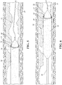
FIGS. 1-6 illustrate side interior views of treatment of a blood vessel in sequence, according to one embodiment, in which: -
FIG. 1 illustrates an interior of the blood vessel with an inner tube assuming a deflated state located therein; -
FIG. 2 illustrates an outer tube or sleeve being slid over the inner tube; -
FIG. 3 illustrates the outer tube slid further along the inner tube, and the inner tube being slightly inflated; -
FIG. 4 illustrates the inner tube and outer tube advancing together through the vessel as the outer tube cuts blockages from the vessel; -
FIG. 5 illustrates the inner tube being further inflated; and -
FIG. 6 illustrates the inner tube and outer tube advancing additionally through the vessel as the outer tube cuts blockages from the vessel; - Embodiments of the present disclosure are described herein. It is to be understood, however, that the disclosed embodiments are merely examples and other embodiments can take various and alternative forms. The figures are not necessarily to scale; some features could be exaggerated or minimized to show details of particular components. Therefore, specific structural and functional details disclosed herein are not to be interpreted as limiting, but merely as a representative basis for teaching one skilled in the art to variously employ the embodiments. As those of ordinary skill in the art will understand, various features illustrated and described with reference to any one of the figures can be combined with features illustrated in one or more other figures to produce embodiments that are not explicitly illustrated or described. The combinations of features illustrated provide representative embodiments for typical applications. Various combinations and modifications of the features consistent with the teachings of this disclosure, however, could be desired for particular applications or implementations.
- Directional terms used herein are made with reference to the views and orientations shown in the exemplary figures. A central axis is shown in the figures and described below. Terms such as "outer" and "inner" are relative to the central axis. For example, an "outer" surface means that the surfaces faces away from the central axis, or is outboard of another "inner" surface. Terms such as "radial," "diameter," "circumference," etc. also are relative to the central axis. The terms "front," "rear," "upper" and "lower" designate directions in the drawings to which reference is made.
- Unless otherwise indicated, for the delivery system the terms "distal" and "proximal" are used in the following description with respect to a position or direction relative to a treating clinician. "Distal" and "distally" are positions distant from or in a direction away from the clinician, and "proximal" and "proximally" are positions near or in a direction toward the clinician. For the stent-graft prosthesis, "proximal" is the portion nearer the heart by way of blood flow path while "distal" is the portion of the stent-graft further from the heart by way of blood flow path.
- The following detailed description is merely exemplary in nature and is not intended to limit the invention or the application and uses of the invention. Although the description is in the context of treatment of blood vessels such as the aorta, coronary, carotid and renal arteries, the invention may also be used in any other body passageways where it is deemed useful.
- The use of percutaneous endovascular procedures has been well established as a minimally invasive technique to deliver a variety of clinical treatments in the patient's vasculature. One unmet challenge still to be addressed by commercially-available devices is the ability to remove a blockage (such as plaque from hard, calcified occluded lesions) from a blood vessel in order to restore the physiological blood flow through the vessel. References to a "blockage" herein is intended to refer to one or more lesions, stenoses, plaque, or any other similar type of infliction or obstruction within a blood vessel that would constrict blood flow within that vessel.
- Therefore, according to various embodiments described herein, an endovascular catheter is disclosed with blockage-cutting features. The blockage-cutting features may include teeth, serrations, or the like and may be located at a leading edge of a lumen in the catheter, for example. As the lumen is advanced along the blood vessel, the blockage-cutting features can cut or score the blockage. Also, the diameter of the lumen may be adjustable. In embodiments explained herein, an inflatable tube may be placed inside the lumen, wherein inflation and deflation of the tube may corresponding expand and contract the lumen.
- Referring to
FIG. 1 , an occludedarterial blood vessel 10 is shown withvarious blockages 12 that, if left untreated, may inhibit blood flow through thevessel 10. Theblood vessel 10 has an outer diameter (OD) and an inner diameter (ID). The OD is defined between an outer wall 14 of thevessel 10. The ID is constricted and varies drastically throughout thevessel 10 due to the prevalence ofblockages 12 therein. - A
guidewire 20 is shown inserted in thevessel 10. Theguidewire 20 can be inserted into theblood vessel 10 via an endovascular procedure in which theguidewire 20 is first inserted into the patient's skin, and is fed along one or more blood vessels until arriving at the desiredblood vessel 10 for treatment to take place. Theguidewire 20 may be made of various thicknesses, materials, and flexibilities. For example, theguidewire 20 may be a nitinol guidewire such as NITREX or BABYWIRE. - In one embodiment, a shaft or
inner tube 22 is provided over theguidewire 20. Theinner tube 22 can also be referred to as a lumen, catheter tube, inner shaft, or the like. Theinner tube 22 can be or include adedicated lumen 24 for tracking over theguidewire 20. In application, once theguidewire 20 is properly positioned in the desiredvessel 10, thelumen 24 can be slid over theguidewire 20 and advanced along theguidewire 20 until theinner tube 22 itself reaches the desired location in thevessel 10. -
FIG. 1 shows theinner tube 22 located at an initial or first linear position within thevessel 10, prior to treatment of theblockages 12. As will be explained below and shown in the remaining Figures, theinner tube 22 can be advanced further into theblood vessel 10 during cutting or scoring of theblockages 12. - The
inner tube 22 can also include or be coupled to an inflatable element 26 (e.g., an inflatable balloon or the like) that can adjust in diameter. Theinflatable element 26 can assume both a deflated configuration and an inflated configuration. Theinflatable element 26 is shown in the deflated configuration inFIG. 1 . Theinflatable element 26 may be integrally formed with theinner tube 22. For example, theinflatable element 26 and thelumen 24 may be a singular component. Theinflatable element 26 may be a sealed chamber disposed radially outward of a central aperture or dedicated lumen of the inner tube 22 (that receives the guidewire 20) so that a fluid medium (e.g., water or saline) performing the inflation of theinflatable element 26 is kept separate and does not contact theguidewire 20. In another embodiment, theinflatable element 26 is a separately-attached component that is configured to assemble to an outer surface of theinner tube 22 orlumen 24. In another embodiment, theinner tube 22 can have a multi-lumen design and structure, with one lumen dedicated to theinflatable element 26 and another dedicated to contain theguidewire 20. -
FIG. 2 illustrates an introduction of anouter tube 30 into the treatment area of thevessel 10. Theouter tube 30 can also be referred to as a sleeve, lumen, catheter tube, or the like. Theouter tube 30 can be a single-lumen configuration with blockage-cutting tips at a distal end thereof (as will be described further below). Theouter tube 30 is made of a flexible yet durable material, allowing theouter tube 30 to slide over the outer diameter of theinner tube 22. Theouter tube 30 is designed to have rigid longitudinal mechanical properties such that mechanical forces transmitted to theouter tube 30 from the proximal end thereof (e.g., from the operator of the catheter) would be mechanically transferred to adistal end 32 with high efficiency (high "pushability"). Theouter tube 30 can be made of, for example, Nitinol, or a combination or Nitinol with other metals and polymers, or other super-elastic alloys due to their elasticity and ability to deform and recoil back to their initial shape without any permanent changes. A material structure similar to that of the covered stents (e.g., polymer fabric sewn onto super-elastic, expandable metal frame) can also be appropriate. - As shown in
FIG. 2 , theouter tube 30 can be slid over a proximal end of theinner tube 22, and advanced toward the distal end of theinner tube 22. InFIG. 2 , theinner tube 22 and itsinflatable element 26 are maintained in the deflated configuration, allowing ease of longitudinal movement of theouter tube 30 relative to theinner tube 22. In this configuration, the unbiased, natural-state inner diameter of theouter tube 30 exceeds at least a portion of the outer diameter of theinner tube 22 and/orinflatable element 26 to facilitate the relative movement of theouter tube 30 along theinner tube 22. Theinner tube 22, theouter tube 30, and any associated handle or control device (not shown) can be referred to as a catheter or a catheter system for placement along theguidewire 20. -
FIG. 3 shows further advancement of theouter tube 30 relative to theinner tube 22. Theinner tube 22 and itsinflatable element 26 may be maintained in the deflated configuration to allow the further advancement of theouter tube 30 relative to theinner tube 22. During advancement of theouter tube 30, the flexible material properties of theouter tube 30 are such that theouter tube 30 can conform to the shape of theinner tube 22 during such advancement. - Once the
distal end 32outer tube 30 has reached a desired location along the distal portion of theinner tube 22, theinflatable element 26 can be inflated to the inflated configuration. According to one embodiment, the inflation of theinflatable element 26 can be performed by an operator, such as a surgical technician. The operator can pump fluid (e.g., saline, etc.) into theinflatable element 26, thus expanding the diameter of theinflatable element 26. The design of theinflatable element 26 can be such that a direct relationship exists between the inflation pressure used by the operator and the outer dimension of theinflatable element 26, so that inflation to a given pressure will result in a given, known outer diameter of theinflatable element 26. The inflation process would allow the operator to control the dimensional profile of the distal end of the device with respect to the blood vessel through changes in inflation pressure. - The material of the
outer tube 30 may be such that it maintains a generally uniform diameter throughout the length of theouter tube 30, regardless of the shape or size of theinner tube 22. This can be seen inFIG. 3 , for example, in which the distal end of theinner tube 22 begins to taper inwardly toward theguidewire 20 while the diameter of theouter tube 30 remains constant. This can create aradial gap 31 between theinner tube 22 and theouter tube 30 at thedistal end 32 of theouter tube 30. This also keeps radial separation between the blockage-cutting features 34 (described below) and theinner tube 22, allowing the blockage-cutting feature to slice through the blockage without interference from theinner tube 22. - Inflation of the
inflatable element 26 can provide at least two functions. First, the inflation couples theinner tube 22 to theouter tube 30 via an outwardly-directed force between an outer surface of theinner tube 22 and an inner surface of theouter tube 30. This force, via inflation, allows theinner tube 22 andouter tube 30 to move along theguidewire 20 in unison; as either theinner tube 22 orouter tube 30 is forced along theguidewire 20, the other of theinner tube 22 orouter tube 30 will be moved along with. It can be said that theinner tube 22 andouter tube 30 are therefore laterally locked. Second, the inflation expands the size of the diameter of theouter tube 30. A controlled amount of inflation may be provided by the operator, and therefore the size of the diameter of theouter tube 30 can be correspondingly controlled. This allows the operator to expand or contract the size of the blockage-cutting tips at thedistal end 32 of theouter tube 30, thus altering the size of the cutting to be performed on theblockages 12, as will be described further below. -
FIG. 4 shows advancement of the laterally-lockedinner tube 22 andouter tube 30 in unison. Since, as explained above, theinner tube 22 andouter tube 30 are locked due to the inflation of theinner tube 22, theinner tube 22 andouter tube 30 can be moved together along the vasculature in the distal direction. This movement may be performed by a surgical technician via a pushing motion, or operation of a handle, for example. In some embodiments, the movement of theouter tube 30 may be only axial in nature (e.g., in the direction of the blood vessel). The axial movement may be continuous or it may be reciprocating (e.g., alternating between pushing and retracting, like a jack-hammer). In other embodiments, theouter tube 30 may be rotated as it is advanced axially. Either type of motion may be performed manually by a physician or technician. However, in other embodiments, the motion may be performed using a motor (e.g., electric motor) coupled to theouter tube 30 and/orinner tube 22. The motor may be controlled by a physician/technician directly or it may be controlled by a robotic surgery system. The direction of rotation and/or axial motion and/or radial velocity of the controlled system can be modulated in relation to the dimension, location, morphology of the vessel and blockage. - As shown in
FIGS. 2-4 , thedistal end 32 of theouter tube 30 is provided with blockage-cutting features 34. The blockage-cutting features may include teeth, serrations, or the like and may be located at a leading edge (e.g., the distal end 32) of theouter tube 30. In one embodiment, the blockage-cutting features are teeth arranged annularly about the circumference of thedistal end 32 with the points of the teeth directed parallel to the central longitudinal axis of theouter tube 30. The blockage-cutting features may be triangular in shape, with or without additional serrations thereon. In at least one embodiment, the cutting features extend completely around the circumference of thedistal end 32 of the outer tube, although in other embodiments there may be annular gaps between cutting sections. - In another embodiment, the blockage-cutting features may be arranged at a location more proximal than the
distal end 32. In an embodiment, the blockage-cutting features may additionally or alternatively face radially outwardly from the central axis of theouter tube 30 - As can be seen in comparing
FIG. 3 withFIG. 4 , as theouter tube 30 is moved along thevessel 10,various blockages 12 have been scraped to widen the overall blood-flow diameter within thevessel 10. As theouter tube 30 is moved along thevessel 10, the blockage-cuttingfeature 34 engage theblockages 12 and remove at least a portion of theblockages 12. This creates an overall unobstructed blood-flow diameter within thevessel 10 of an amount at least equivalent to the diameter of theouter tube 30. - To create a wider diameter of the
outer tube 30, and therefore a wider blood-flow diameter within thevessel 10, theinner tube 22 can be further inflated.FIG. 5 illustrates one embodiment of this. InFIG. 5 , it can be seen that theinner tube 22 has been further inflated via similar operations as described above. This correspondingly expands the diameter of theouter tube 30, allowing the blockage-cutting features 34 to engagecertain blockages 13 that may not have been engageable when theouter tube 30 was its previous diameter (e.g.,FIG. 4 ). By selectively inflating and deflating theinner tube 22 during operation, a surgical technician can select the proper diameter for cutting or scoring thevarious blockages vessel 10. This also allows the overall dimensions of theouter tube 30 to be varied for different sizes of blood vessels. For example, as theinner tube 22 andouter tube 30 are inserted into the patient, they may initially travel along smaller vessels (e.g., iliac artery) until reaching a larger vessel (e.g., aorta). As theinner tube 22 andouter tube 30 enter the aorta, theinner tube 22 can be inflated to a larger size to provide a larger cutting profile than was previously provided during travel in the iliac artery. Also,FIG. 5 shows the overall catheter system being slightly retracted, illustrating one embodiment of proximal and distal movement being possible during a procedure. - In one example, the
outer tube 30 and blockage-cutting features 34 may make multiple passes at the same location in a blood vessel to sequentially increase the size of the unobstructed vessel. A first pass may be performed with the outer tube at a first diameter to remove a portion of a blockage. After the first pass, theouter tube 30 andinner tube 22 may be retracted and the diameter of the inflatable element may be increased, thereby also increasing the diameter of theouter tube 30. A second pass may then be performed to remove an additional radial thickness of the blockage due to the increased diameter of theouter tube 30. Additional cycles of retracting, increasing the diameter, and performing another pass may be sequentially performed until the physician has removed a desired amount of the blockage. The number of passes may depend on the magnitude of the blockage, the hardness of the blockage (e.g., harder blockages may need smaller/more passes), the size of the vessel, or other factors. This process may be repeated at multiple axial locations in the vessel. -
FIG. 6 shows an embodiment similar toFIG. 5 , except now showing anouter tube 30 with more flexibility at aproximal end 36 thereof, and theinner tube 22 andouter tube 30 being advanced more through thevessel 10. In this embodiment, theouter tube 30 is relatively rigid at itsdistal end 32 so that theradial gap 31 is maintained between theinner tube 22 and theouter tube 30. Meanwhile, theouter tube 30 can be relatively flexible (e.g., more flexible than the distal end 32) at itsproximal end 36 such that theouter tube 30 conforms to the shape of theinner tube 22 at theproximal end 36. And, with advancement of the catheter system, theblockages 13 once present inFIG. 5 are now removed. - After the blockages are cut or scored according to the teachings above, the blockage can be extracted and removed from the
vessel 10. In one example, the removed material may be extracted with a separate removal system, not shown herein. In another example, the cut/scored material may be lodged between theouter tube 30 and theinner tube 22/inflatable element 26. For example, when theinflatable element 26 is deflated, theouter tube 30 may attempt to return to its natural diameter, thereby trapping the removed material between itself and theinflatable element 26. Once a certain amount of the blockage has been removed, the inner and outer tubes may be removed from the body to clear away the removed material. If additional blockages remain to be removed, the inner and outer tubes may be re-inserted and additional removal steps may be performed. This process may be repeated as many times as necessary. - In another example, an aspiration system may be incorporated into the system, either as a separate component or as part of one of the components described herein. The aspiration system may be disposed proximal to the
distal end 32 ofouter tube 30 such that it can aspirate/suck removed material once it is cut/scored. The aspiration system may be connected to a source of vacuum/suction in the operating room. By intermittently or continuously aspirating, more cutting passes may be performed without removing the outer tube from the body. In embodiments, the teachings above may be implemented into an atherectomy system, such as a rotational or directional atherectomy system, that includes an atherosclerosis-removal feature, for example. - Embodiments disclosed herein illustrate the
outer tube 30 being separately attached around theinner tube 22. However, in another embodiment, theouter tube 30 is integral with the inflatable member 26 (e.g., balloon) such that the blockage-cutting features are part of a single, unitary device surrounding theguidewire 20. - While exemplary embodiments are described above, it is not intended that these embodiments describe all possible forms encompassed by the claims. The words used in the specification are words of description rather than limitation, and it is understood that various changes can be made without departing from the spirit and scope of the disclosure. As previously described, the features of various embodiments can be combined to form further embodiments of the invention that may not be explicitly described or illustrated. While various embodiments could have been described as providing advantages or being preferred over other embodiments or prior art implementations with respect to one or more desired characteristics, those of ordinary skill in the art recognize that one or more features or characteristics can be compromised to achieve desired overall system attributes, which depend on the specific application and implementation. These attributes can include, but are not limited to cost, strength, durability, life cycle cost, marketability, appearance, packaging, size, serviceability, weight, manufacturability, ease of assembly, etc. As such, to the extent any embodiments are described as less desirable than other embodiments or prior art implementations with respect to one or more characteristics, these embodiments are not outside the scope of the disclosure and can be desirable for particular applications.
- Further disclosed herein is the subject-matter of the following clauses:
- 1. An endovascular catheter system configured to remove a blockage in a vessel of a patient, the endovascular catheter comprising:
- an inflatable inner tube configured to operate in a deflated configuration and an inflated configuration; and
- an expandable outer tube configured to advance longitudinally over the inner tube when the inner tube is in the deflated configuration, the outer tube including a leading edge having blockage-cutting features configured to remove at least a portion of the blockage in the vessel;
- wherein the outer tube is made of a radially-expandable material such that inflation of the inner tube to the inflated configuration when the outer tube is located about the inner tube causes the outer tube to expand radially.
- 2. The endovascular catheter system of clause 1, wherein the inner tube has a dedicated central lumen configured to travel along an outer surface of a guidewire.
- 3. The endovascular catheter system of clause 1 or of any of the preceding clauses, wherein the leading edge defines a circumference, and the blockage-cutting features extend from the circumference.
- 4. The endovascular catheter system of clause 3, wherein the outer tube extends along an axis, and the blockage-cutting features extend in a direction parallel to the axis.
- 5. The endovascular catheter system of clause 1 or of any of the preceding clauses, wherein the inner tube and outer tube are slideable relative to each other when the inner tube is in the deflated configuration.
- 6. The endovascular catheter system of clause 5, wherein the inner tube is locked to the outer tube when the inner tube is in the inflated configuration such that the inner tube and outer tube move in unison.
- 7. An endovascular catheter system comprising:
- an inner tube extending between a proximal end and a distal end, the distal end being a tapered distal end tapering radially inwardly; and
- a sleeve extending between a proximal end and a distal end and configured to slide over the inner tube, wherein the distal end of the sleeve and the tapered distal end of the inner tube define a radial gap therebetween, wherein the distal end of the sleeve includes blockage-cutting features configured to remove blockages within a blood vessel of a patient.
- 8. The endovascular catheter system of clause 7, wherein the inner tube is configured to operate in a deflated state and an inflated state.
- 9. The endovascular catheter system of clause 8, wherein the sleeve is flexible such that the sleeve expands radially outward as the inner tube inflates to the inflated state.
- 10. The endovascular catheter system of clause 8, wherein the sleeve is sized such that the sleeve can slide along the inner tube when operating in the deflated state.
- 11. The endovascular catheter system of
clause 10, wherein inflation of the inner tube to the inflated state locks the sleeve to the inner tube. - 12. The endovascular catheter system of clause 8 or of any of any of clauses 8-11, wherein the sleeve extends along a length, and the blockage-cutting features extend from the distal end of the sleeve in a direction parallel to the length.
- 13. The endovascular catheter system of
clause 12, wherein the blockage cutting features are teeth or serrations. - 14. The endovascular catheter system of clause 8 or of any of any of clauses 8-13, wherein the inner tube includes a dedicated central lumen configured to track along a guidewire.
- 15. A method for treating a blood vessel having blockages therein, the method comprising:
- tracking an inner tube along a guidewire to a desired location in the blood vessel;
- then advancing an outer tube over the inner tube, wherein the outer tube includes blockage-cutting features;
- then inflating the inner tube to expand the outer tube; and
- then advancing the inner tube and outer tube together through the blood vessel to enable the blockage-cutting feature to cut blockages in the blood vessel.
- 16. The method of clause 15, wherein the step of tracking includes tracking a dedicated central lumen of the inner tube along the guidewire.
- 17. The method of clause 15, further comprising, after the step of advancing the inner tube and outer tube together, further inflating the inner tube to further expand the outer tube.
- 18. The method of clause 17, further comprising, after the step of further inflating, further advancing the inner tube and outer tube together.
- 19. The method of clause 15, wherein the step of inflating locks the outer tube to the inner tube.
- 20. The method of clause 15, further comprising, after the step of advancing the inner tube and outer tube together, deflating the inner tube and retracting the outer tube from the vessel.
Claims (14)
- An endovascular catheter system configured to remove a blockage in a vessel of a patient, the endovascular catheter comprising:an inflatable inner tube configured to operate in a deflated configuration and an inflated configuration; andan expandable outer tube configured to advance longitudinally over the inner tube when the inner tube is in the deflated configuration, the outer tube including a leading edge having blockage-cutting features configured to remove at least a portion of the blockage in the vessel;wherein the outer tube is made of a radially-expandable material such that inflation of the inner tube to the inflated configuration when the outer tube is located about the inner tube causes the outer tube to expand radially.
- The endovascular catheter system of claim 1, wherein the inner tube has a dedicated central lumen configured to travel along an outer surface of a guidewire.
- The endovascular catheter system of any of the preceding claims, wherein the leading edge defines a circumference, and the blockage-cutting features extend from the circumference.
- The endovascular catheter system of claim 3, wherein the outer tube extends along an axis, and the blockage-cutting features extend in a direction parallel to the axis.
- The endovascular catheter system of any of the preceding claims, wherein the inner tube and outer tube are slideable relative to each other when the inner tube is in the deflated configuration.
- The endovascular catheter system of claim 5, wherein the inner tube is locked to the outer tube when the inner tube is in the inflated configuration such that the inner tube and outer tube move in unison.
- An endovascular catheter system comprising:an inner tube extending between a proximal end and a distal end, the distal end being a tapered distal end tapering radially inwardly; anda sleeve extending between a proximal end and a distal end and configured to slide over the inner tube, wherein the distal end of the sleeve and the tapered distal end of the inner tube define a radial gap therebetween, wherein the distal end of the sleeve includes blockage-cutting features configured to remove blockages within a blood vessel of a patient.
- The endovascular catheter system of claim 7, wherein the inner tube is configured to operate in a deflated state and an inflated state.
- The endovascular catheter system of claim 8, wherein the sleeve is flexible such that the sleeve expands radially outward as the inner tube inflates to the inflated state.
- The endovascular catheter system of claim 8, wherein the sleeve is sized such that the sleeve can slide along the inner tube when operating in the deflated state.
- The endovascular catheter system of claim 10, wherein inflation of the inner tube to the inflated state locks the sleeve to the inner tube.
- The endovascular catheter system of any of claims 8-11, wherein the sleeve extends along a length, and the blockage-cutting features extend from the distal end of the sleeve in a direction parallel to the length.
- The endovascular catheter system of claim 12, wherein the blockage cutting features are teeth or serrations.
- The endovascular catheter system of any of claims 8-13, wherein the inner tube includes a dedicated central lumen configured to track along a guidewire.
Applications Claiming Priority (1)
| Application Number | Priority Date | Filing Date | Title |
|---|---|---|---|
| US16/802,740 US11369408B2 (en) | 2020-02-27 | 2020-02-27 | Adjustable blockage-cutting device |
Publications (2)
| Publication Number | Publication Date |
|---|---|
| EP3871619A1 true EP3871619A1 (en) | 2021-09-01 |
| EP3871619B1 EP3871619B1 (en) | 2024-09-04 |
Family
ID=74732606
Family Applications (1)
| Application Number | Title | Priority Date | Filing Date |
|---|---|---|---|
| EP21158703.5A Active EP3871619B1 (en) | 2020-02-27 | 2021-02-23 | Adjustable blockage-cutting device |
Country Status (2)
| Country | Link |
|---|---|
| US (1) | US11369408B2 (en) |
| EP (1) | EP3871619B1 (en) |
Citations (4)
| Publication number | Priority date | Publication date | Assignee | Title |
|---|---|---|---|---|
| US20050080478A1 (en) * | 2003-10-10 | 2005-04-14 | Barongan Mark Gelido | Cutting stent |
| US20060178685A1 (en) * | 2004-12-30 | 2006-08-10 | Cook Incorporated | Balloon expandable plaque cutting device |
| US7279002B2 (en) * | 2003-04-25 | 2007-10-09 | Boston Scientific Scimed, Inc. | Cutting stent and balloon |
| CN110063768A (en) * | 2019-04-04 | 2019-07-30 | 深圳市业聚实业有限公司 | A kind of Cutting balloon |
Family Cites Families (7)
| Publication number | Priority date | Publication date | Assignee | Title |
|---|---|---|---|---|
| US5908435A (en) * | 1997-10-23 | 1999-06-01 | Samuels; Shaun L. W. | Expandable lumen device and method of use |
| US20030212384A1 (en) * | 2002-05-10 | 2003-11-13 | Hayden Scott William | Expandable interventional system |
| US20070198047A1 (en) | 2005-12-20 | 2007-08-23 | Medical Components, Inc. | Cutting balloon catheter assembly |
| US20110034937A1 (en) * | 2009-08-07 | 2011-02-10 | TD.JAM Medical Technologies, LLC | Revascularization Device for Treating an Occluded Arterial Vessel |
| GB2478592B (en) | 2010-03-12 | 2012-02-29 | Cook Medical Technologies Llc | Obstruction removal assembly and method |
| US8801736B2 (en) * | 2010-11-19 | 2014-08-12 | Gil Vardi | Percutaneous thrombus extraction device and method |
| US10456160B2 (en) * | 2015-03-09 | 2019-10-29 | Teleflex Innovations S.À.R.L. | Stenotic region scoring assembly and method |
-
2020
- 2020-02-27 US US16/802,740 patent/US11369408B2/en active Active
-
2021
- 2021-02-23 EP EP21158703.5A patent/EP3871619B1/en active Active
Patent Citations (4)
| Publication number | Priority date | Publication date | Assignee | Title |
|---|---|---|---|---|
| US7279002B2 (en) * | 2003-04-25 | 2007-10-09 | Boston Scientific Scimed, Inc. | Cutting stent and balloon |
| US20050080478A1 (en) * | 2003-10-10 | 2005-04-14 | Barongan Mark Gelido | Cutting stent |
| US20060178685A1 (en) * | 2004-12-30 | 2006-08-10 | Cook Incorporated | Balloon expandable plaque cutting device |
| CN110063768A (en) * | 2019-04-04 | 2019-07-30 | 深圳市业聚实业有限公司 | A kind of Cutting balloon |
Also Published As
| Publication number | Publication date |
|---|---|
| US11369408B2 (en) | 2022-06-28 |
| US20210267626A1 (en) | 2021-09-02 |
| EP3871619B1 (en) | 2024-09-04 |
Similar Documents
| Publication | Publication Date | Title |
|---|---|---|
| US12274822B2 (en) | Atherectomy device | |
| JP7659579B2 (en) | Intravascular delivery system and method for percutaneous coronary intervention - Patents.com | |
| US9692557B2 (en) | Apparatus and methods for administering treatment within a bodily duct of a patient | |
| US5792158A (en) | University dilator with expandable incisor | |
| US5649941A (en) | Improved vascular incisor/dilator | |
| EP0829238B1 (en) | Incisor-dilator with tapered balloon | |
| US6805692B2 (en) | Aspiration method | |
| US20100010521A1 (en) | Cutting balloon with movable member | |
| CA3197631A1 (en) | Catheters having shaped distal portions, and associated systems and methods | |
| US20120271231A1 (en) | Aspiration thrombectomy device | |
| US20090099581A1 (en) | Methods and apparatus for treating vascular occlusions | |
| US20030144677A1 (en) | Reciprocating cutting and dilating balloon | |
| US20070060942A2 (en) | Method and Apparatus for Emboli Containment | |
| US20070198047A1 (en) | Cutting balloon catheter assembly | |
| JPH03272754A (en) | Catheter | |
| JPH0822289B2 (en) | Atherectomy catheter assembly | |
| US9750517B2 (en) | Method of aspirating a thrombus accumulation between a venous valve and a vein wall | |
| EP3253438B1 (en) | Apparatus and methods for administering treatment within a bodily duct of a patient | |
| EP2181728A1 (en) | Balloon Catheter | |
| EP3932341B1 (en) | Intravascular plaque isolation, destabilization, and aspiration | |
| EP4353165A1 (en) | Cutting balloon catheter with concealed blades | |
| US20180021054A1 (en) | Systems and methods for crossing and treating an occlusion | |
| WO2016126369A1 (en) | Apparatus and methods for administering treatment within a bodily duct of a patient | |
| EP3871619B1 (en) | Adjustable blockage-cutting device | |
| US20240374878A1 (en) | Scraper Balloon Catheter Device |
Legal Events
| Date | Code | Title | Description |
|---|---|---|---|
| PUAI | Public reference made under article 153(3) epc to a published international application that has entered the european phase |
Free format text: ORIGINAL CODE: 0009012 |
|
| STAA | Information on the status of an ep patent application or granted ep patent |
Free format text: STATUS: THE APPLICATION HAS BEEN PUBLISHED |
|
| AK | Designated contracting states |
Kind code of ref document: A1 Designated state(s): AL AT BE BG CH CY CZ DE DK EE ES FI FR GB GR HR HU IE IS IT LI LT LU LV MC MK MT NL NO PL PT RO RS SE SI SK SM TR |
|
| STAA | Information on the status of an ep patent application or granted ep patent |
Free format text: STATUS: REQUEST FOR EXAMINATION WAS MADE |
|
| 17P | Request for examination filed |
Effective date: 20220301 |
|
| RBV | Designated contracting states (corrected) |
Designated state(s): AL AT BE BG CH CY CZ DE DK EE ES FI FR GB GR HR HU IE IS IT LI LT LU LV MC MK MT NL NO PL PT RO RS SE SI SK SM TR |
|
| STAA | Information on the status of an ep patent application or granted ep patent |
Free format text: STATUS: EXAMINATION IS IN PROGRESS |
|
| 17Q | First examination report despatched |
Effective date: 20230404 |
|
| RIC1 | Information provided on ipc code assigned before grant |
Ipc: A61M 25/02 20060101ALN20240201BHEP Ipc: A61B 17/22 20060101ALN20240201BHEP Ipc: A61M 25/10 20130101ALI20240201BHEP Ipc: A61B 17/3207 20060101AFI20240201BHEP |
|
| GRAP | Despatch of communication of intention to grant a patent |
Free format text: ORIGINAL CODE: EPIDOSNIGR1 |
|
| STAA | Information on the status of an ep patent application or granted ep patent |
Free format text: STATUS: GRANT OF PATENT IS INTENDED |
|
| INTG | Intention to grant announced |
Effective date: 20240321 |
|
| GRAS | Grant fee paid |
Free format text: ORIGINAL CODE: EPIDOSNIGR3 |
|
| GRAA | (expected) grant |
Free format text: ORIGINAL CODE: 0009210 |
|
| STAA | Information on the status of an ep patent application or granted ep patent |
Free format text: STATUS: THE PATENT HAS BEEN GRANTED |
|
| AK | Designated contracting states |
Kind code of ref document: B1 Designated state(s): AL AT BE BG CH CY CZ DE DK EE ES FI FR GB GR HR HU IE IS IT LI LT LU LV MC MK MT NL NO PL PT RO RS SE SI SK SM TR |
|
| REG | Reference to a national code |
Ref country code: GB Ref legal event code: FG4D |
|
| REG | Reference to a national code |
Ref country code: CH Ref legal event code: EP |
|
| REG | Reference to a national code |
Ref country code: IE Ref legal event code: FG4D |
|
| REG | Reference to a national code |
Ref country code: DE Ref legal event code: R096 Ref document number: 602021018129 Country of ref document: DE |
|
| REG | Reference to a national code |
Ref country code: LT Ref legal event code: MG9D |
|
| REG | Reference to a national code |
Ref country code: NL Ref legal event code: MP Effective date: 20240904 |
|
| PG25 | Lapsed in a contracting state [announced via postgrant information from national office to epo] |
Ref country code: NO Free format text: LAPSE BECAUSE OF FAILURE TO SUBMIT A TRANSLATION OF THE DESCRIPTION OR TO PAY THE FEE WITHIN THE PRESCRIBED TIME-LIMIT Effective date: 20241204 |
|
| PG25 | Lapsed in a contracting state [announced via postgrant information from national office to epo] |
Ref country code: GR Free format text: LAPSE BECAUSE OF FAILURE TO SUBMIT A TRANSLATION OF THE DESCRIPTION OR TO PAY THE FEE WITHIN THE PRESCRIBED TIME-LIMIT Effective date: 20241205 Ref country code: PL Free format text: LAPSE BECAUSE OF FAILURE TO SUBMIT A TRANSLATION OF THE DESCRIPTION OR TO PAY THE FEE WITHIN THE PRESCRIBED TIME-LIMIT Effective date: 20240904 Ref country code: FI Free format text: LAPSE BECAUSE OF FAILURE TO SUBMIT A TRANSLATION OF THE DESCRIPTION OR TO PAY THE FEE WITHIN THE PRESCRIBED TIME-LIMIT Effective date: 20240904 |
|
| PG25 | Lapsed in a contracting state [announced via postgrant information from national office to epo] |
Ref country code: BG Free format text: LAPSE BECAUSE OF FAILURE TO SUBMIT A TRANSLATION OF THE DESCRIPTION OR TO PAY THE FEE WITHIN THE PRESCRIBED TIME-LIMIT Effective date: 20240904 |
|
| PG25 | Lapsed in a contracting state [announced via postgrant information from national office to epo] |
Ref country code: LV Free format text: LAPSE BECAUSE OF FAILURE TO SUBMIT A TRANSLATION OF THE DESCRIPTION OR TO PAY THE FEE WITHIN THE PRESCRIBED TIME-LIMIT Effective date: 20240904 |
|
| PG25 | Lapsed in a contracting state [announced via postgrant information from national office to epo] |
Ref country code: HR Free format text: LAPSE BECAUSE OF FAILURE TO SUBMIT A TRANSLATION OF THE DESCRIPTION OR TO PAY THE FEE WITHIN THE PRESCRIBED TIME-LIMIT Effective date: 20240904 |
|
| PG25 | Lapsed in a contracting state [announced via postgrant information from national office to epo] |
Ref country code: ES Free format text: LAPSE BECAUSE OF FAILURE TO SUBMIT A TRANSLATION OF THE DESCRIPTION OR TO PAY THE FEE WITHIN THE PRESCRIBED TIME-LIMIT Effective date: 20240904 Ref country code: RS Free format text: LAPSE BECAUSE OF FAILURE TO SUBMIT A TRANSLATION OF THE DESCRIPTION OR TO PAY THE FEE WITHIN THE PRESCRIBED TIME-LIMIT Effective date: 20241204 |
|
| PG25 | Lapsed in a contracting state [announced via postgrant information from national office to epo] |
Ref country code: RS Free format text: LAPSE BECAUSE OF FAILURE TO SUBMIT A TRANSLATION OF THE DESCRIPTION OR TO PAY THE FEE WITHIN THE PRESCRIBED TIME-LIMIT Effective date: 20241204 Ref country code: PL Free format text: LAPSE BECAUSE OF FAILURE TO SUBMIT A TRANSLATION OF THE DESCRIPTION OR TO PAY THE FEE WITHIN THE PRESCRIBED TIME-LIMIT Effective date: 20240904 Ref country code: NO Free format text: LAPSE BECAUSE OF FAILURE TO SUBMIT A TRANSLATION OF THE DESCRIPTION OR TO PAY THE FEE WITHIN THE PRESCRIBED TIME-LIMIT Effective date: 20241204 Ref country code: LV Free format text: LAPSE BECAUSE OF FAILURE TO SUBMIT A TRANSLATION OF THE DESCRIPTION OR TO PAY THE FEE WITHIN THE PRESCRIBED TIME-LIMIT Effective date: 20240904 Ref country code: HR Free format text: LAPSE BECAUSE OF FAILURE TO SUBMIT A TRANSLATION OF THE DESCRIPTION OR TO PAY THE FEE WITHIN THE PRESCRIBED TIME-LIMIT Effective date: 20240904 Ref country code: GR Free format text: LAPSE BECAUSE OF FAILURE TO SUBMIT A TRANSLATION OF THE DESCRIPTION OR TO PAY THE FEE WITHIN THE PRESCRIBED TIME-LIMIT Effective date: 20241205 Ref country code: FI Free format text: LAPSE BECAUSE OF FAILURE TO SUBMIT A TRANSLATION OF THE DESCRIPTION OR TO PAY THE FEE WITHIN THE PRESCRIBED TIME-LIMIT Effective date: 20240904 Ref country code: ES Free format text: LAPSE BECAUSE OF FAILURE TO SUBMIT A TRANSLATION OF THE DESCRIPTION OR TO PAY THE FEE WITHIN THE PRESCRIBED TIME-LIMIT Effective date: 20240904 Ref country code: BG Free format text: LAPSE BECAUSE OF FAILURE TO SUBMIT A TRANSLATION OF THE DESCRIPTION OR TO PAY THE FEE WITHIN THE PRESCRIBED TIME-LIMIT Effective date: 20240904 |
|
| REG | Reference to a national code |
Ref country code: AT Ref legal event code: MK05 Ref document number: 1719551 Country of ref document: AT Kind code of ref document: T Effective date: 20240904 |
|
| PG25 | Lapsed in a contracting state [announced via postgrant information from national office to epo] |
Ref country code: NL Free format text: LAPSE BECAUSE OF FAILURE TO SUBMIT A TRANSLATION OF THE DESCRIPTION OR TO PAY THE FEE WITHIN THE PRESCRIBED TIME-LIMIT Effective date: 20240904 |
|
| PG25 | Lapsed in a contracting state [announced via postgrant information from national office to epo] |
Ref country code: IS Free format text: LAPSE BECAUSE OF FAILURE TO SUBMIT A TRANSLATION OF THE DESCRIPTION OR TO PAY THE FEE WITHIN THE PRESCRIBED TIME-LIMIT Effective date: 20250104 Ref country code: PT Free format text: LAPSE BECAUSE OF FAILURE TO SUBMIT A TRANSLATION OF THE DESCRIPTION OR TO PAY THE FEE WITHIN THE PRESCRIBED TIME-LIMIT Effective date: 20250106 |
|
| PG25 | Lapsed in a contracting state [announced via postgrant information from national office to epo] |
Ref country code: RO Free format text: LAPSE BECAUSE OF FAILURE TO SUBMIT A TRANSLATION OF THE DESCRIPTION OR TO PAY THE FEE WITHIN THE PRESCRIBED TIME-LIMIT Effective date: 20240904 Ref country code: SM Free format text: LAPSE BECAUSE OF FAILURE TO SUBMIT A TRANSLATION OF THE DESCRIPTION OR TO PAY THE FEE WITHIN THE PRESCRIBED TIME-LIMIT Effective date: 20240904 |
|
| PG25 | Lapsed in a contracting state [announced via postgrant information from national office to epo] |
Ref country code: AT Free format text: LAPSE BECAUSE OF FAILURE TO SUBMIT A TRANSLATION OF THE DESCRIPTION OR TO PAY THE FEE WITHIN THE PRESCRIBED TIME-LIMIT Effective date: 20240904 Ref country code: EE Free format text: LAPSE BECAUSE OF FAILURE TO SUBMIT A TRANSLATION OF THE DESCRIPTION OR TO PAY THE FEE WITHIN THE PRESCRIBED TIME-LIMIT Effective date: 20240904 |
|
| PG25 | Lapsed in a contracting state [announced via postgrant information from national office to epo] |
Ref country code: CZ Free format text: LAPSE BECAUSE OF FAILURE TO SUBMIT A TRANSLATION OF THE DESCRIPTION OR TO PAY THE FEE WITHIN THE PRESCRIBED TIME-LIMIT Effective date: 20240904 |
|
| PG25 | Lapsed in a contracting state [announced via postgrant information from national office to epo] |
Ref country code: IT Free format text: LAPSE BECAUSE OF FAILURE TO SUBMIT A TRANSLATION OF THE DESCRIPTION OR TO PAY THE FEE WITHIN THE PRESCRIBED TIME-LIMIT Effective date: 20240904 Ref country code: SK Free format text: LAPSE BECAUSE OF FAILURE TO SUBMIT A TRANSLATION OF THE DESCRIPTION OR TO PAY THE FEE WITHIN THE PRESCRIBED TIME-LIMIT Effective date: 20240904 |
|
| REG | Reference to a national code |
Ref country code: DE Ref legal event code: R097 Ref document number: 602021018129 Country of ref document: DE |
|
| PG25 | Lapsed in a contracting state [announced via postgrant information from national office to epo] |
Ref country code: DK Free format text: LAPSE BECAUSE OF FAILURE TO SUBMIT A TRANSLATION OF THE DESCRIPTION OR TO PAY THE FEE WITHIN THE PRESCRIBED TIME-LIMIT Effective date: 20240904 |
|
| PLBE | No opposition filed within time limit |
Free format text: ORIGINAL CODE: 0009261 |
|
| STAA | Information on the status of an ep patent application or granted ep patent |
Free format text: STATUS: NO OPPOSITION FILED WITHIN TIME LIMIT |
|
| 26N | No opposition filed |
Effective date: 20250605 |
|
| PG25 | Lapsed in a contracting state [announced via postgrant information from national office to epo] |
Ref country code: SE Free format text: LAPSE BECAUSE OF FAILURE TO SUBMIT A TRANSLATION OF THE DESCRIPTION OR TO PAY THE FEE WITHIN THE PRESCRIBED TIME-LIMIT Effective date: 20240904 |
|
| PG25 | Lapsed in a contracting state [announced via postgrant information from national office to epo] |
Ref country code: MC Free format text: LAPSE BECAUSE OF FAILURE TO SUBMIT A TRANSLATION OF THE DESCRIPTION OR TO PAY THE FEE WITHIN THE PRESCRIBED TIME-LIMIT Effective date: 20240904 |
|
| REG | Reference to a national code |
Ref country code: CH Ref legal event code: PL |
|
| PG25 | Lapsed in a contracting state [announced via postgrant information from national office to epo] |
Ref country code: LU Free format text: LAPSE BECAUSE OF NON-PAYMENT OF DUE FEES Effective date: 20250223 |
|
| PG25 | Lapsed in a contracting state [announced via postgrant information from national office to epo] |
Ref country code: CH Free format text: LAPSE BECAUSE OF NON-PAYMENT OF DUE FEES Effective date: 20250228 |
|
| GBPC | Gb: european patent ceased through non-payment of renewal fee |
Effective date: 20250223 |
|
| REG | Reference to a national code |
Ref country code: BE Ref legal event code: MM Effective date: 20250228 |
|
| PG25 | Lapsed in a contracting state [announced via postgrant information from national office to epo] |
Ref country code: GB Free format text: LAPSE BECAUSE OF NON-PAYMENT OF DUE FEES Effective date: 20250223 |
|
| PG25 | Lapsed in a contracting state [announced via postgrant information from national office to epo] |
Ref country code: BE Free format text: LAPSE BECAUSE OF NON-PAYMENT OF DUE FEES Effective date: 20250228 |
|
| PG25 | Lapsed in a contracting state [announced via postgrant information from national office to epo] |
Ref country code: IE Free format text: LAPSE BECAUSE OF NON-PAYMENT OF DUE FEES Effective date: 20250223 |
|
| PGFP | Annual fee paid to national office [announced via postgrant information from national office to epo] |
Ref country code: DE Payment date: 20260121 Year of fee payment: 6 |
|
| PGFP | Annual fee paid to national office [announced via postgrant information from national office to epo] |
Ref country code: FR Payment date: 20260121 Year of fee payment: 6 |