EP3871578A1 - Nozzle for a cleaning device - Google Patents
Nozzle for a cleaning device Download PDFInfo
- Publication number
- EP3871578A1 EP3871578A1 EP20159886.9A EP20159886A EP3871578A1 EP 3871578 A1 EP3871578 A1 EP 3871578A1 EP 20159886 A EP20159886 A EP 20159886A EP 3871578 A1 EP3871578 A1 EP 3871578A1
- Authority
- EP
- European Patent Office
- Prior art keywords
- substance
- nozzle
- electrical conductors
- deformed
- region
- Prior art date
- Legal status (The legal status is an assumption and is not a legal conclusion. Google has not performed a legal analysis and makes no representation as to the accuracy of the status listed.)
- Granted
Links
Images

Classifications
-
- A—HUMAN NECESSITIES
- A47—FURNITURE; DOMESTIC ARTICLES OR APPLIANCES; COFFEE MILLS; SPICE MILLS; SUCTION CLEANERS IN GENERAL
- A47L—DOMESTIC WASHING OR CLEANING; SUCTION CLEANERS IN GENERAL
- A47L9/00—Details or accessories of suction cleaners, e.g. mechanical means for controlling the suction or for effecting pulsating action; Storing devices specially adapted to suction cleaners or parts thereof; Carrying-vehicles specially adapted for suction cleaners
- A47L9/20—Means for cleaning filters
Definitions
- the present disclosure relates to a nozzle for a cleaning device.
- Cleaning devices including for example vacuum cleaners, carpet or upholstery cleaners, etc.
- the nozzles are typically formed of a hard, rigid plastics material.
- a user can select a particular nozzle according to the item to be cleaned.
- one nozzle may be relatively broad and flat to be suitable for vacuuming a floor
- another nozzle may be somewhat triangular in section and relatively narrow and flat for vacuuming stairs or furniture
- another nozzle may be relatively long and narrow to fit into crevices in furniture, corners between a floor and walls or corners between adjacent walls, etc.
- the manufacturer has to manufacture and supply a number of nozzles of different shapes and the user has to store the different nozzles.
- the limited number of different nozzles may not be suitable to fit in or around all items to be cleaned.
- a nozzle for a cleaning device comprising:
- the shape of the nozzle can be adjusted to fit an item to be cleaned or to fit around an item during cleaning.
- the shape of the nozzle can be adjusted as necessary to enable cleaning of a floor, cleaning in a crevice in furniture, cleaning in corners between a floor and walls or corners between adjacent walls, under furniture, etc. This provides for better cleaning.
- This also avoids the need for the manufacturer to make and supply a number of different nozzle attachments of different shapes and sizes, and also avoids the end user having to store and use a number of different nozzle attachments of different shapes and sizes.
- the user needs simply to press the nozzle against or into the region to be cleaned, and allow or enable an electric current to flow through the closed circuit conductors. This causes localised heating of the substance, such that the shape of the nozzle can then easily be adjusted to fit against or into the region to be cleaned better.
- the nozzle may be used with a cleaning device, such as for example a vacuum cleaner, a carpet or upholstery cleaner, etc.
- the nozzle may be provided as a separate attachment, which can for example be removably fixed to a hose or wand or the like of the cleaning device, or may be provided as a fixed, permanent nozzle of the cleaning device.
- the substance is or comprises a wax.
- the wax may be for example beeswax.
- the wax may comprise one or more other natural or synthetic waxes.
- Other substances other than wax may be used, as an alternative to or in addition to wax.
- the body is formed of a compressible material which contains said substance.
- the compressible material may be for example in the form of a sponge or sponge-like material.
- the substance is contained in a plurality of flexible containers which are contained within the compressible material.
- the flexible containers act like balloons or balls which contain the substance within the body of the nozzle.
- the flexible containers may be formed of for example a plastics or rubber or a rubber-like material, which may be natural and/or synthetic.
- At least some of the containers have separate first and second chambers, the first chamber containing the substance and the second chamber containing a gas or mixture of gases.
- the second chamber may for example contain air.
- an advantage of this is that a small amount of compression can be applied initially to the nozzle to cause at least some of the electric conductors at said deformed region to become closed circuit as the gaseous chambers can easily compress. Once the electric conductors become closed circuit, heating of the substance at said deformed region allows a greater deformation to be applied to the nozzle, which allows greater changes to the shape of the nozzle to be made.
- the flexible containers are arranged in rows, wherein the electrical conductors pass through or are adjacent respective rows of the flexible containers, and wherein electrical conductors of adjacent rows in a region of the body can be brought into contact with each other when the region of the body is deformed thereby to cause said electrical conductors to become closed circuit.
- the compressible material comprises a reinforcing web.
- the web may for example be woven or non-woven.
- the web may for example be formed of a polymer, including for example a nylon.
- the body comprises a plurality of fibres to provide rigidity to the compressible material, the fibres crossing each other to provide a scissor action as the body is compressed.
- the nozzle 10 is for a cleaning device, such as for example a vacuum cleaner, a carpet or upholstery cleaner, etc.
- the nozzle 10 may be provided as a separate part which can be detachably fixed to a hose or rigid wand 12 or the like of the cleaning device or may be provided integrally with the hose or rigid wand 12 or the like of the cleaning device.
- the example nozzle 10 shown in Figure 1 is in a configuration that is suitable for cleaning a floor, for example, and is therefore relatively broad (wide) and flat.
- the configuration, and particularly the shape, of the nozzle 10 can be adjusted to be different. This enables the user to adjust the shape of the nozzle 10 to be more suitable for cleaning different items or to fit better around different items during cleaning.
- the user can cause the shape of the nozzle 10 to change to mimic other standard nozzles that are conventionally provided with current cleaning devices, including for example, in the case of vacuum cleaners, floor cleaning nozzles, crevice tools, extension wands, upholstery tools, etc.
- the user can cause the shape of the nozzle 10 to be different from standard nozzles. This enables the nozzle 10 to fit better into or around awkwardly shaped items, and can fit better than standard nozzles. In any event, this avoids the manufacturer having to make and supply, and avoids the user having to store, a number of different shape nozzles.
- the nozzle 10 has a body 14.
- the body 14 is formed of or contains a substance 16 that is relatively rigid at room temperature and that is relatively malleable at a temperature above room temperature.
- room temperature may for example be defined as around 20 to 22 °C or so.
- An example of a suitable material for the substance 16 include a wax, for example beeswax.
- Beeswax is in general relatively rigid at room temperature but becomes soft and pliable above around 35 to 40 °C or so.
- the wax may comprise one or more other natural or synthetic waxes.
- wax other substances other than wax may be used, as an alternative to or in addition to wax, including for example some industrial solid oils (such as grease, which generally consists of a soap emulsified with mineral or vegetable oil), some solid fats (including for example vegetable fats), etc.
- industrial solid oils such as grease, which generally consists of a soap emulsified with mineral or vegetable oil
- solid fats including for example vegetable fats
- the nozzle 10 has a plurality of electrical conductors 18.
- the electrical conductors 18 may be formed of for example copper, aluminium or similar.
- the electrical conductors 18 are in thermal contact with the substance 16.
- any substance 16 that is in the region of the electrical conductors 18 that are conducting electricity heats up through resistive heating. This causes the substance 16 to be more malleable. This enables the shape of the body 14 of the nozzle 10 to be adjusted.
- the electrical conductors 18 are normally open circuit such that a current does not normally flow through the electrical conductors 18.
- the electrical conductors 18 can be made to be closed circuit so that they can conduct an electric current and therefore cause localised heating of the substance 16.
- the body 14 could be formed substantially only of the substance 16, optionally contained within some flexible outer housing or the like. However, as illustrated most clearly in Figure 2 , in this example the body 14 is formed of a compressible material 20 which contains the substance 16.
- the compressible material 20 may be for example in the form of a sponge or a s.
- the compressible material 20 is basically airtight, that is generally not permeable to air, as it in effect forms a main part of the body 14 of the nozzle 10. Having a compressible material 20 assists in allowing a small amount of compression to be applied initially to the nozzle 10 to cause at least some of the electric conductors 18 at the deformed region to become closed circuit (as will be discussed further below). Once the electric conductors 18 become closed circuit, heating of the substance 16 at the deformed region allows a greater deformation to be applied to the nozzle 10, which allows greater changes to the shape of the nozzle 10 to be made.
- the substance 16 is contained within a plurality of flexible containers 22 which themselves are contained within the compressible material 20 of the body 14.
- the flexible containers 22 act like balloons or balls which contain the substance 16 within the compressible material 20.
- the flexible containers 22 may be formed of for example a plastics (such as for example a nylon, polyurethane or polyethylene, etc.) or rubber or a rubber-like material, which may be natural and/or synthetic. It will be understood that the substance 16 is shown schematically in Figure 2 as being in the form of a number of spheres within the containers 22, but in practice the substance 16 is likely to be in the form of a homogeneous block within the individual containers 22.
- the flexible containers 22 can change shape as necessary when the shape of the nozzle 14 is to be changed.
- the flexible containers 22 may be entirely filled with the substance 16.
- the flexible containers 22 are part filled with the substance 16, with the remainder of the flexible containers 22 containing a gas or a mixture of gases, such as most conveniently air.
- a gas or a mixture of gases such as most conveniently air.
- each flexible container 22 having two separate chambers 22a, 22b.
- the chambers 22a, 22b are separated by a wall (not visible in the drawings), which may be made of the same material as or a different material from the remainder of the flexible containers 22.
- One chamber 22a contains the gas or mixture of gases, including for example air.
- the other chamber 22b contains the substance 16.
- the air-filled chamber 22a can easily compress, allowing for the required initial compression to cause the relevant electric conductors 18 to come into contact with each other, and also allows more significant changes to the shape of the nozzle 10 to be achieved.
- the compressible material 20 may be provided with a reinforcing web (not shown) to provide some additional strength to the compressible material 20 and to contain the compressible material 20.
- the web may be provided only around the exterior of the compressible material 20 in order for example to contain the compressible material 20.
- the web may be provided throughout the body of the compressible material 20 to further increase the strength of the compressible material 20.
- the material of the web may be woven or non-woven.
- the web may for example be formed of a polymer, including for example a nylon.
- the body 14 may have a plurality of fibres 24 to provide some rigidity and structure to the nozzle 10 whilst still allowing the nozzle 10 to flex and change shape.
- the fibres 24 may for example be provided throughout the throughout the body of the compressible material 20 as shown schematically in Figure 2 .
- the fibres 24 may be formed of for example one or more of carbon, plastics such as nylon, polyurethane, etc. In this example the fibres 24 are arranged to cross each other. In this way, as the nozzle 10 is compressed or otherwise changes shape, the fibres 24 allow the shape of the compressible material 20 to change by the fibres 24 moving in a scissor-like action. This movement of the fibres 24 may in general be in all three dimensions.
- the fibres 24 can also help restore the nozzle 10 to a default, rest shape or configuration after use.
- the electrical conductors 18 are normally open circuit such that a current does not normally flow through the electrical conductors 18.
- the electrical conductors 18 can be made to be closed circuit so that they can conduct an electric current and therefore cause localised heating of the substance 16, which in turn allows the shape of the body 14 of the nozzle 10 to be changed. In the present example, this is achieved as follows.
- the electrical conductors 18 are arranged in rows 18a, 18b, 18c, etc.
- the electrical conductor 18 of each row 18a, 18b, 18c passes through or is adjacent to a respective row of the flexible containers 22.
- the electrical conductors 18 of adjacent rows 18a, 18b, 18c are not normally in contact with each other and so electric current cannot normally pass between adjacent rows 18a, 18b, 18c of electrical conductors 18.
- the electrical conductor 18 of each row 18a, 18b, 18c has a plurality of connection pins 26.
- the connection pins 26 may be formed of for example nichrome (a non-magnetic 80/20 alloy of nickel and chromium), copper, aluminium or similar.
- connection pins 26 extend laterally of the rows 18a, 18b, 18c of electrical conductors 18, for example perpendicularly of the rows 18a, 18b, 18c of electrical conductors 18.
- the connection pins 26 have a length such that they do not normally make contact with an electrical conductor 18 of an adjacent row.
- the connection pins 26 of one row 18a, 18b, 18c are brought into contact with an adjacent row 18a, 18b, 18c at least at that region of the body 14. In the specific example, this is facilitated by arranging each connection pin 26 of one row to oppose a connection pin 26 of an adjacent row such that connection pins 26 of adjacent rows are paired with each other.
- connection pins 26 it may not be necessary to have the connection pins 26 at all, and instead the adjacent rows of electrical conductors 18 can be brought into contact directly.
- a connection pin 26 on one row may not be opposed to a connection pin 26 on an adjacent row, and instead may be brought into contact with the adjacent row of electrical conductor 18 directory.
- the nozzle 10 may be used as follows.
- a user wishes to clean an item, or wishes to clean round an item. that has shape for which the current shape of the nozzle 10 is not suitable or ideal.
- the user may wish to clean a crevice in furniture or a corner between a floor and a wall or a corner between adjacent walls.
- the user presses the nozzle 10 against the item to be cleaned (or into the crevice, into the corner, etc., as the case may be).
- This causes the body 14 of the nozzle 10 to compress slightly, at least at the region where the nozzle is being pressed against the item to be cleaned. In one example, this slight, initial compression of the body 14 may be achieved only by compression of the compressible material 20.
- this slight initial compression of the body 14 may be achieved partly by compression of the compressible material 20 and partly by some compression of the flexible containers 22.
- compression of the flexible containers 22 may be achieved only by compressing the chambers 22a that contain air or other gas(es) or additionally by some compression of the compressible material 20.
- this slight initial compression of at least a part of the body 14 of the nozzle 10 causes adjacent electrical conductors 18 in the neighbourhood of that part of the body 14 to be brought into contact with each other. Electric current is then caused to flow through those touching electrical conductors 18. This may be achieved by the user pressing an "on" switch. Alternatively or additionally, this may be achieved automatically by some sensing system that detects the closed circuit formed by the touching electrical conductors 18. Such a sensing system may for example use only passive components, such as resistors, etc. or may use sensors and some kind of controller, such as a processor.
- a particular advantage of the nozzle body 14 being formed of or containing a substance 16 that is relatively rigid at room temperature and that is relatively malleable at a temperature above room temperature is that the control of the malleability and rigidity of the substance 16 can be quite straightforward (here, largely by the user pressing the nozzle 10 against the item to be cleaned). It is not necessary to provide complicated circuits to control the malleability of the substance 16 and therefore the nozzle 10 as a whole.
- the amount of initial compression that is required to bring adjacent electrical conductors 18 into electrical contact with each other and the amount of overall change of shape that can be achieved can be tailored by for example varying the amount of the substance 16 as a whole relative to the compressible material 20; the size of the flexible containers 22; the amount of substance 16 in each flexible container 22 relative to the amount of air or other gas(es) in each flexible container 22; the arrangement of the scissor fibres 24; the materials used for each of the different components of the nozzle 14; etc. Further, some parts of the nozzle 10 may need to be reshaped more than others, and so the arrangement of the substance 16, flexible containers 22 and the compressible material 20 may be non-uniform and may be different at different parts of the nozzle 10.
Landscapes
- Engineering & Computer Science (AREA)
- Mechanical Engineering (AREA)
- Nozzles For Electric Vacuum Cleaners (AREA)
- Cleaning Implements For Floors, Carpets, Furniture, Walls, And The Like (AREA)
Abstract
Description
- The present disclosure relates to a nozzle for a cleaning device.
- Cleaning devices, including for example vacuum cleaners, carpet or upholstery cleaners, etc., are often provided with a number of different nozzles (or nozzle "attachments") which have different shapes and configurations. The nozzles are typically formed of a hard, rigid plastics material. A user can select a particular nozzle according to the item to be cleaned. For example, in the case of a vacuum cleaner, one nozzle may be relatively broad and flat to be suitable for vacuuming a floor, another nozzle may be somewhat triangular in section and relatively narrow and flat for vacuuming stairs or furniture, another nozzle may be relatively long and narrow to fit into crevices in furniture, corners between a floor and walls or corners between adjacent walls, etc. However, this means that the manufacturer has to manufacture and supply a number of nozzles of different shapes and the user has to store the different nozzles. Further, the limited number of different nozzles may not be suitable to fit in or around all items to be cleaned.
- According to a first aspect disclosed herein, there is provided a nozzle for a cleaning device, the nozzle comprising:
- a body formed of or containing a substance that is relatively rigid at room temperature and that is relatively malleable at a temperature above room temperature; and
- a plurality of electrical conductors in thermal contact with the substance;
- the electrical conductors being arranged so as to be normally open circuit;
- the electrical conductors being arranged such that when a region of the body is deformed, at least some of the electrical conductors at said deformed region become closed circuit so as to be able to conduct an electric current at said deformed region, thereby heating said substance at said deformed region to allow said substance at said deformed region to be further deformed to fit an item to be cleaned or to fit around an item during cleaning.
- This allows the shape of the nozzle to be adjusted to fit an item to be cleaned or to fit around an item during cleaning. For example, the shape of the nozzle can be adjusted as necessary to enable cleaning of a floor, cleaning in a crevice in furniture, cleaning in corners between a floor and walls or corners between adjacent walls, under furniture, etc. This provides for better cleaning. This also avoids the need for the manufacturer to make and supply a number of different nozzle attachments of different shapes and sizes, and also avoids the end user having to store and use a number of different nozzle attachments of different shapes and sizes. The user needs simply to press the nozzle against or into the region to be cleaned, and allow or enable an electric current to flow through the closed circuit conductors. This causes localised heating of the substance, such that the shape of the nozzle can then easily be adjusted to fit against or into the region to be cleaned better.
- The nozzle may be used with a cleaning device, such as for example a vacuum cleaner, a carpet or upholstery cleaner, etc. The nozzle may be provided as a separate attachment, which can for example be removably fixed to a hose or wand or the like of the cleaning device, or may be provided as a fixed, permanent nozzle of the cleaning device.
- In an example, the substance is or comprises a wax.
- The wax may be for example beeswax. Alternatively or additionally, the wax may comprise one or more other natural or synthetic waxes. Other substances other than wax may be used, as an alternative to or in addition to wax.
- In an example, the body is formed of a compressible material which contains said substance. An advantage of this is that a small amount of compression can be applied initially to the nozzle to cause at least some of the electric conductors at said deformed region to become closed circuit as the compressible material of the body can easily compress somewhat. Once the electric conductors become closed circuit, heating of the substance at said deformed region allows a greater deformation to be applied to the nozzle, which allows greater changes to the shape of the nozzle to be made.
- The compressible material may be for example in the form of a sponge or sponge-like material.
- In an example, the substance is contained in a plurality of flexible containers which are contained within the compressible material.
- The flexible containers act like balloons or balls which contain the substance within the body of the nozzle. The flexible containers may be formed of for example a plastics or rubber or a rubber-like material, which may be natural and/or synthetic.
- In an example, at least some of the containers have separate first and second chambers, the first chamber containing the substance and the second chamber containing a gas or mixture of gases. The second chamber may for example contain air. Similarly to the example above where the body is formed of a compressible material, an advantage of this is that a small amount of compression can be applied initially to the nozzle to cause at least some of the electric conductors at said deformed region to become closed circuit as the gaseous chambers can easily compress. Once the electric conductors become closed circuit, heating of the substance at said deformed region allows a greater deformation to be applied to the nozzle, which allows greater changes to the shape of the nozzle to be made.
- In an example, the flexible containers are arranged in rows, wherein the electrical conductors pass through or are adjacent respective rows of the flexible containers, and wherein electrical conductors of adjacent rows in a region of the body can be brought into contact with each other when the region of the body is deformed thereby to cause said electrical conductors to become closed circuit.
- In an example, the compressible material comprises a reinforcing web. The web may for example be woven or non-woven. The web may for example be formed of a polymer, including for example a nylon.
- In an example, the body comprises a plurality of fibres to provide rigidity to the compressible material, the fibres crossing each other to provide a scissor action as the body is compressed.
- To assist understanding of the present disclosure and to show how embodiments may be put into effect, reference is made by way of example to the accompanying drawings in which:
-
Figure 1 shows schematically a perspective view of an example of a nozzle according to the present disclosure; and -
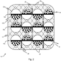
Figure 2 shows schematically a cross-sectional view through part of the nozzle ofFigure 1 . - Referring to the drawings, there is shown schematically an example of a
nozzle 10 according to the present disclosure. Thenozzle 10 is for a cleaning device, such as for example a vacuum cleaner, a carpet or upholstery cleaner, etc. Thenozzle 10 may be provided as a separate part which can be detachably fixed to a hose orrigid wand 12 or the like of the cleaning device or may be provided integrally with the hose orrigid wand 12 or the like of the cleaning device. - The
example nozzle 10 shown inFigure 1 is in a configuration that is suitable for cleaning a floor, for example, and is therefore relatively broad (wide) and flat. As will be explained, the configuration, and particularly the shape, of thenozzle 10 can be adjusted to be different. This enables the user to adjust the shape of thenozzle 10 to be more suitable for cleaning different items or to fit better around different items during cleaning. The user can cause the shape of thenozzle 10 to change to mimic other standard nozzles that are conventionally provided with current cleaning devices, including for example, in the case of vacuum cleaners, floor cleaning nozzles, crevice tools, extension wands, upholstery tools, etc. Further, the user can cause the shape of thenozzle 10 to be different from standard nozzles. This enables thenozzle 10 to fit better into or around awkwardly shaped items, and can fit better than standard nozzles. In any event, this avoids the manufacturer having to make and supply, and avoids the user having to store, a number of different shape nozzles. - The
nozzle 10 has abody 14. Thebody 14 is formed of or contains asubstance 16 that is relatively rigid at room temperature and that is relatively malleable at a temperature above room temperature. In general, room temperature may for example be defined as around 20 to 22 °C or so. An example of a suitable material for thesubstance 16 include a wax, for example beeswax. Beeswax is in general relatively rigid at room temperature but becomes soft and pliable above around 35 to 40 °C or so. Alternatively or additionally to beeswax, the wax may comprise one or more other natural or synthetic waxes. Other substances other than wax may be used, as an alternative to or in addition to wax, including for example some industrial solid oils (such as grease, which generally consists of a soap emulsified with mineral or vegetable oil), some solid fats (including for example vegetable fats), etc. - The
nozzle 10 has a plurality ofelectrical conductors 18. Theelectrical conductors 18 may be formed of for example copper, aluminium or similar. Theelectrical conductors 18 are in thermal contact with thesubstance 16. When an electric current flows through (some of) theelectrical conductors 18, anysubstance 16 that is in the region of theelectrical conductors 18 that are conducting electricity heats up through resistive heating. This causes thesubstance 16 to be more malleable. This enables the shape of thebody 14 of thenozzle 10 to be adjusted. As will be explained by further discussion of the specific example below, theelectrical conductors 18 are normally open circuit such that a current does not normally flow through theelectrical conductors 18. Theelectrical conductors 18 can be made to be closed circuit so that they can conduct an electric current and therefore cause localised heating of thesubstance 16. - The
body 14 could be formed substantially only of thesubstance 16, optionally contained within some flexible outer housing or the like. However, as illustrated most clearly inFigure 2 , in this example thebody 14 is formed of a compressible material 20 which contains thesubstance 16. The compressible material 20 may be for example in the form of a sponge or a s. The compressible material 20 is basically airtight, that is generally not permeable to air, as it in effect forms a main part of thebody 14 of thenozzle 10. Having a compressible material 20 assists in allowing a small amount of compression to be applied initially to thenozzle 10 to cause at least some of theelectric conductors 18 at the deformed region to become closed circuit (as will be discussed further below). Once theelectric conductors 18 become closed circuit, heating of thesubstance 16 at the deformed region allows a greater deformation to be applied to thenozzle 10, which allows greater changes to the shape of thenozzle 10 to be made. - In the example shown, the
substance 16 is contained within a plurality of flexible containers 22 which themselves are contained within the compressible material 20 of thebody 14. The flexible containers 22 act like balloons or balls which contain thesubstance 16 within the compressible material 20. The flexible containers 22 may be formed of for example a plastics (such as for example a nylon, polyurethane or polyethylene, etc.) or rubber or a rubber-like material, which may be natural and/or synthetic. It will be understood that thesubstance 16 is shown schematically inFigure 2 as being in the form of a number of spheres within the containers 22, but in practice thesubstance 16 is likely to be in the form of a homogeneous block within the individual containers 22. The flexible containers 22 can change shape as necessary when the shape of thenozzle 14 is to be changed. - In this regard, the flexible containers 22 may be entirely filled with the
substance 16. In another example, as shown inFigure 2 , the flexible containers 22 are part filled with thesubstance 16, with the remainder of the flexible containers 22 containing a gas or a mixture of gases, such as most conveniently air. An advantage of this is that it (also) assists in allowing a small amount of compression to be applied initially to thenozzle 10 to cause at least some of theelectric conductors 18 at the deformed region to become closed circuit (as will be discussed further below) because the gaseous part enables the containers 22 to compress more easily. Once theelectric conductors 18 become closed circuit, heating of thesubstance 16 at the deformed region allows a greater deformation to be applied to thenozzle 10, which allows greater changes to the shape of thenozzle 10 to be made. This also enables the shape of the flexible containers 22 to be changed more dramatically or significantly than if for example the flexible containers 22 are completely filled with thesubstance 16. In the example shown, this is achieved by each flexible container 22 having twoseparate chambers chambers chamber 22a contains the gas or mixture of gases, including for example air. Theother chamber 22b contains thesubstance 16. When the shape of thenozzle 10 is to be changed, the air-filledchamber 22a can easily compress, allowing for the required initial compression to cause the relevantelectric conductors 18 to come into contact with each other, and also allows more significant changes to the shape of thenozzle 10 to be achieved. - Returning to the compressible material 20, the compressible material 20 may be provided with a reinforcing web (not shown) to provide some additional strength to the compressible material 20 and to contain the compressible material 20. The web may be provided only around the exterior of the compressible material 20 in order for example to contain the compressible material 20. In another example, the web may be provided throughout the body of the compressible material 20 to further increase the strength of the compressible material 20. The material of the web may be woven or non-woven. The web may for example be formed of a polymer, including for example a nylon.
- Further, the
body 14 may have a plurality offibres 24 to provide some rigidity and structure to thenozzle 10 whilst still allowing thenozzle 10 to flex and change shape. Thefibres 24 may for example be provided throughout the throughout the body of the compressible material 20 as shown schematically inFigure 2 . Thefibres 24 may be formed of for example one or more of carbon, plastics such as nylon, polyurethane, etc. In this example thefibres 24 are arranged to cross each other. In this way, as thenozzle 10 is compressed or otherwise changes shape, thefibres 24 allow the shape of the compressible material 20 to change by thefibres 24 moving in a scissor-like action. This movement of thefibres 24 may in general be in all three dimensions. Thefibres 24 can also help restore thenozzle 10 to a default, rest shape or configuration after use. - Returning now to the
electrical conductors 18, as mentioned, these are normally open circuit such that a current does not normally flow through theelectrical conductors 18. On the other hand, theelectrical conductors 18 can be made to be closed circuit so that they can conduct an electric current and therefore cause localised heating of thesubstance 16, which in turn allows the shape of thebody 14 of thenozzle 10 to be changed. In the present example, this is achieved as follows. - Referring to
Figure 2 , theelectrical conductors 18 are arranged inrows electrical conductor 18 of eachrow electrical conductors 18 ofadjacent rows adjacent rows electrical conductors 18. Theelectrical conductor 18 of eachrow rows electrical conductors 18, for example perpendicularly of therows electrical conductors 18. The connection pins 26 have a length such that they do not normally make contact with anelectrical conductor 18 of an adjacent row. On the other hand, when thebody 14 is sufficiently compressed, at least at a particular region of thebody 14, the connection pins 26 of onerow adjacent row body 14. In the specific example, this is facilitated by arranging eachconnection pin 26 of one row to oppose aconnection pin 26 of an adjacent row such that connection pins 26 of adjacent rows are paired with each other. Other arrangements are possible. For example, it may not be necessary to have the connection pins 26 at all, and instead the adjacent rows ofelectrical conductors 18 can be brought into contact directly. As another example, aconnection pin 26 on one row may not be opposed to aconnection pin 26 on an adjacent row, and instead may be brought into contact with the adjacent row ofelectrical conductor 18 directory. - In use, the
nozzle 10 may be used as follows. - Suppose a user wishes to clean an item, or wishes to clean round an item. that has shape for which the current shape of the
nozzle 10 is not suitable or ideal. For example, the user may wish to clean a crevice in furniture or a corner between a floor and a wall or a corner between adjacent walls. The user presses thenozzle 10 against the item to be cleaned (or into the crevice, into the corner, etc., as the case may be). This causes thebody 14 of thenozzle 10 to compress slightly, at least at the region where the nozzle is being pressed against the item to be cleaned. In one example, this slight, initial compression of thebody 14 may be achieved only by compression of the compressible material 20. In another example, this slight initial compression of thebody 14 may be achieved partly by compression of the compressible material 20 and partly by some compression of the flexible containers 22. In the example shown, compression of the flexible containers 22 may be achieved only by compressing thechambers 22a that contain air or other gas(es) or additionally by some compression of the compressible material 20. - In any event, this slight initial compression of at least a part of the
body 14 of thenozzle 10 causes adjacentelectrical conductors 18 in the neighbourhood of that part of thebody 14 to be brought into contact with each other. Electric current is then caused to flow through those touchingelectrical conductors 18. This may be achieved by the user pressing an "on" switch. Alternatively or additionally, this may be achieved automatically by some sensing system that detects the closed circuit formed by the touchingelectrical conductors 18. Such a sensing system may for example use only passive components, such as resistors, etc. or may use sensors and some kind of controller, such as a processor. - Current flowing through the touching
electrical conductors 18 causes heating of thesubstance 16 that is in the neighbourhood of the touchingelectrical conductors 18. This causes thesubstance 16 to become relatively more malleable. The user can continue to push thenozzle 10 against the item to be cleaned (or into the crevice, into the corner, etc., as the case may be). Now, because thesubstance 16 is malleable, at least in and near the region where thenozzle 10 is being pushed against the item, thebody 14 of thenozzle 10 can change shape easily and, most pertinently, so that thenozzle 10 can better fit the item to be cleaned. That is, thenozzle 10 moulds itself to fit in or around the item to be cleaned. The electric current through theelectrical conductors 18 can then be switched off. This allows thesubstance 16 to cool down and therefore become less malleable and more rigid, which gives greater rigidity to thenozzle 10 as a whole. The user can then clean the item as desired. As thenozzle 10 fits the item to be cleaned more accurately and completely, more effective cleaning can be carried out. This is achieved without the user having to change thenozzle 10 for a different shape one. - A particular advantage of the
nozzle body 14 being formed of or containing asubstance 16 that is relatively rigid at room temperature and that is relatively malleable at a temperature above room temperature is that the control of the malleability and rigidity of thesubstance 16 can be quite straightforward (here, largely by the user pressing thenozzle 10 against the item to be cleaned). It is not necessary to provide complicated circuits to control the malleability of thesubstance 16 and therefore thenozzle 10 as a whole. - It is described above that a slight compression of the
nozzle 10 is used initially to bring adjacentelectrical conductors 18 into electrical contact with each other. This is then followed by potentially large or significant changes of shape of thenozzle 10 once thesubstance 16 has been heated, at least in the regions where thenozzle 10 is being compressed. The amount of initial compression that is required to bring adjacentelectrical conductors 18 into electrical contact with each other and the amount of overall change of shape that can be achieved can be tailored by for example varying the amount of thesubstance 16 as a whole relative to the compressible material 20; the size of the flexible containers 22; the amount ofsubstance 16 in each flexible container 22 relative to the amount of air or other gas(es) in each flexible container 22; the arrangement of thescissor fibres 24; the materials used for each of the different components of thenozzle 14; etc. Further, some parts of thenozzle 10 may need to be reshaped more than others, and so the arrangement of thesubstance 16, flexible containers 22 and the compressible material 20 may be non-uniform and may be different at different parts of thenozzle 10. - The examples described herein are to be understood as illustrative examples of embodiments of the invention. Further embodiments and examples are envisaged. Any feature described in relation to any one example or embodiment may be used alone or in combination with other features. In addition, any feature described in relation to any one example or embodiment may also be used in combination with one or more features of any other of the examples or embodiments, or any combination of any other of the examples or embodiments. Furthermore, equivalents and modifications not described herein may also be employed within the scope of the invention, which is defined in the claims.
Claims (8)
- A nozzle for a cleaning device, the nozzle comprising:a body formed of or containing a substance that is relatively rigid at room temperature and that is relatively malleable at a temperature above room temperature; anda plurality of electrical conductors in thermal contact with the substance;the electrical conductors being arranged so as to be normally open circuit;the electrical conductors being arranged such that when a region of the body is deformed, at least some of the electrical conductors at said deformed region become closed circuit so as to be able to conduct an electric current at said deformed region, thereby heating said substance at said deformed region to allow said substance at said deformed region to be further deformed to fit an item to be cleaned or to fit around an item during cleaning.
- A nozzle according to claim 1, wherein the substance is or comprises a wax.
- A nozzle according to claim 1 or claim 2, wherein the body is formed of a compressible material which contains said substance.
- A nozzle according to claim 3, wherein the substance is contained in a plurality of flexible containers which are contained within the compressible material.
- A nozzle according to claim 4, wherein at least some of the containers have separate first and second chambers, the first chamber containing the substance and the second chamber containing a gas or mixture of gases.
- A nozzle according to claim 4 or claim 5, wherein the flexible containers are arranged in rows, wherein the electrical conductors pass through or are adjacent respective rows of the flexible containers, and wherein electrical conductors of adjacent rows in a region of the body can be brought into contact with each other when the region of the body is deformed thereby to cause said electrical conductors to become closed circuit.
- A nozzle according to any of claims 3 to 6, wherein the compressible material comprises a reinforcing web.
- A nozzle according to any of claims 3 to 7, wherein the body comprises a plurality of fibres to provide rigidity to the compressible material, the fibres crossing each other to provide a scissor action as the body is compressed.
Priority Applications (1)
| Application Number | Priority Date | Filing Date | Title |
|---|---|---|---|
| EP20159886.9A EP3871578B1 (en) | 2020-02-27 | 2020-02-27 | Nozzle for a cleaning device |
Applications Claiming Priority (1)
| Application Number | Priority Date | Filing Date | Title |
|---|---|---|---|
| EP20159886.9A EP3871578B1 (en) | 2020-02-27 | 2020-02-27 | Nozzle for a cleaning device |
Publications (2)
| Publication Number | Publication Date |
|---|---|
| EP3871578A1 true EP3871578A1 (en) | 2021-09-01 |
| EP3871578B1 EP3871578B1 (en) | 2023-08-23 |
Family
ID=69742825
Family Applications (1)
| Application Number | Title | Priority Date | Filing Date |
|---|---|---|---|
| EP20159886.9A Active EP3871578B1 (en) | 2020-02-27 | 2020-02-27 | Nozzle for a cleaning device |
Country Status (1)
| Country | Link |
|---|---|
| EP (1) | EP3871578B1 (en) |
Citations (2)
| Publication number | Priority date | Publication date | Assignee | Title |
|---|---|---|---|---|
| GB790469A (en) * | 1955-10-06 | 1958-02-12 | Gen Electric | Improvements in vacuum cleaner tools |
| WO2018059679A1 (en) * | 2016-09-28 | 2018-04-05 | Alfred Kärcher Gmbh & Co. Kg | Suction nozzle and a hard-surface suction device |
-
2020
- 2020-02-27 EP EP20159886.9A patent/EP3871578B1/en active Active
Patent Citations (2)
| Publication number | Priority date | Publication date | Assignee | Title |
|---|---|---|---|---|
| GB790469A (en) * | 1955-10-06 | 1958-02-12 | Gen Electric | Improvements in vacuum cleaner tools |
| WO2018059679A1 (en) * | 2016-09-28 | 2018-04-05 | Alfred Kärcher Gmbh & Co. Kg | Suction nozzle and a hard-surface suction device |
Also Published As
| Publication number | Publication date |
|---|---|
| EP3871578B1 (en) | 2023-08-23 |
Similar Documents
| Publication | Publication Date | Title |
|---|---|---|
| CA2386604C (en) | Device for the wiping and cleaning of soiled surfaces | |
| US8205293B2 (en) | Steam mop | |
| CN101116603B (en) | Steam mop | |
| EP4205622A1 (en) | Surface cleaning apparatus with steam delivery | |
| US2237969A (en) | Cushioned mop handle | |
| EP0684006B1 (en) | Vacuum cleaner having a steam jetting apparatus | |
| CN202739935U (en) | Steam appliance with diffuser | |
| EP4726257A2 (en) | Extraction cleaner with steam | |
| JP2013064317A (en) | Floor finish application assembly and method | |
| GB2435819A (en) | Bare floor cleaner | |
| WO2005023079A2 (en) | Multi-purpose cleaning implement | |
| JP2005506178A (en) | Ultrasonic cleaning equipment | |
| EP3871578B1 (en) | Nozzle for a cleaning device | |
| CN107405040A (en) | Cleaning device | |
| US2882642A (en) | Carpet stretcher | |
| US3063084A (en) | Car washing article with water distributing head | |
| US20150135473A1 (en) | Cleaning Apparatus | |
| AU707887B2 (en) | Cleaning unit | |
| US20080202567A1 (en) | Multi Function Cleaner | |
| JP7414387B2 (en) | vacuum cleaner suction tool | |
| JP2011113386A (en) | Input interface device | |
| TR202003015A2 (en) | NOZZLE FOR A CLEANING DEVICE | |
| EP1594388B1 (en) | Handgrip for a domestic cleaning-appliance nozzle | |
| JP2001310343A (en) | Nonwoven fabric and nonwoven fabric manufacturing method | |
| CN216787344U (en) | Manual formula pull throughs |
Legal Events
| Date | Code | Title | Description |
|---|---|---|---|
| PUAI | Public reference made under article 153(3) epc to a published international application that has entered the european phase |
Free format text: ORIGINAL CODE: 0009012 |
|
| STAA | Information on the status of an ep patent application or granted ep patent |
Free format text: STATUS: THE APPLICATION HAS BEEN PUBLISHED |
|
| AK | Designated contracting states |
Kind code of ref document: A1 Designated state(s): AL AT BE BG CH CY CZ DE DK EE ES FI FR GB GR HR HU IE IS IT LI LT LU LV MC MK MT NL NO PL PT RO RS SE SI SK SM TR |
|
| STAA | Information on the status of an ep patent application or granted ep patent |
Free format text: STATUS: REQUEST FOR EXAMINATION WAS MADE |
|
| 17P | Request for examination filed |
Effective date: 20220125 |
|
| RBV | Designated contracting states (corrected) |
Designated state(s): AL AT BE BG CH CY CZ DE DK EE ES FI FR GB GR HR HU IE IS IT LI LT LU LV MC MK MT NL NO PL PT RO RS SE SI SK SM TR |
|
| GRAP | Despatch of communication of intention to grant a patent |
Free format text: ORIGINAL CODE: EPIDOSNIGR1 |
|
| STAA | Information on the status of an ep patent application or granted ep patent |
Free format text: STATUS: GRANT OF PATENT IS INTENDED |
|
| INTG | Intention to grant announced |
Effective date: 20230310 |
|
| GRAS | Grant fee paid |
Free format text: ORIGINAL CODE: EPIDOSNIGR3 |
|
| GRAA | (expected) grant |
Free format text: ORIGINAL CODE: 0009210 |
|
| STAA | Information on the status of an ep patent application or granted ep patent |
Free format text: STATUS: THE PATENT HAS BEEN GRANTED |
|
| AK | Designated contracting states |
Kind code of ref document: B1 Designated state(s): AL AT BE BG CH CY CZ DE DK EE ES FI FR GB GR HR HU IE IS IT LI LT LU LV MC MK MT NL NO PL PT RO RS SE SI SK SM TR |
|
| REG | Reference to a national code |
Ref country code: GB Ref legal event code: FG4D |
|
| REG | Reference to a national code |
Ref country code: CH Ref legal event code: EP |
|
| REG | Reference to a national code |
Ref country code: IE Ref legal event code: FG4D |
|
| REG | Reference to a national code |
Ref country code: DE Ref legal event code: R096 Ref document number: 602020016025 Country of ref document: DE |
|
| REG | Reference to a national code |
Ref country code: LT Ref legal event code: MG9D |
|
| REG | Reference to a national code |
Ref country code: NL Ref legal event code: MP Effective date: 20230823 |
|
| REG | Reference to a national code |
Ref country code: AT Ref legal event code: MK05 Ref document number: 1601570 Country of ref document: AT Kind code of ref document: T Effective date: 20230823 |
|
| PG25 | Lapsed in a contracting state [announced via postgrant information from national office to epo] |
Ref country code: GR Free format text: LAPSE BECAUSE OF FAILURE TO SUBMIT A TRANSLATION OF THE DESCRIPTION OR TO PAY THE FEE WITHIN THE PRESCRIBED TIME-LIMIT Effective date: 20231124 |
|
| PG25 | Lapsed in a contracting state [announced via postgrant information from national office to epo] |
Ref country code: IS Free format text: LAPSE BECAUSE OF FAILURE TO SUBMIT A TRANSLATION OF THE DESCRIPTION OR TO PAY THE FEE WITHIN THE PRESCRIBED TIME-LIMIT Effective date: 20231223 |
|
| PG25 | Lapsed in a contracting state [announced via postgrant information from national office to epo] |
Ref country code: SE Free format text: LAPSE BECAUSE OF FAILURE TO SUBMIT A TRANSLATION OF THE DESCRIPTION OR TO PAY THE FEE WITHIN THE PRESCRIBED TIME-LIMIT Effective date: 20230823 Ref country code: RS Free format text: LAPSE BECAUSE OF FAILURE TO SUBMIT A TRANSLATION OF THE DESCRIPTION OR TO PAY THE FEE WITHIN THE PRESCRIBED TIME-LIMIT Effective date: 20230823 Ref country code: PT Free format text: LAPSE BECAUSE OF FAILURE TO SUBMIT A TRANSLATION OF THE DESCRIPTION OR TO PAY THE FEE WITHIN THE PRESCRIBED TIME-LIMIT Effective date: 20231226 Ref country code: NO Free format text: LAPSE BECAUSE OF FAILURE TO SUBMIT A TRANSLATION OF THE DESCRIPTION OR TO PAY THE FEE WITHIN THE PRESCRIBED TIME-LIMIT Effective date: 20231123 Ref country code: NL Free format text: LAPSE BECAUSE OF FAILURE TO SUBMIT A TRANSLATION OF THE DESCRIPTION OR TO PAY THE FEE WITHIN THE PRESCRIBED TIME-LIMIT Effective date: 20230823 Ref country code: LV Free format text: LAPSE BECAUSE OF FAILURE TO SUBMIT A TRANSLATION OF THE DESCRIPTION OR TO PAY THE FEE WITHIN THE PRESCRIBED TIME-LIMIT Effective date: 20230823 Ref country code: LT Free format text: LAPSE BECAUSE OF FAILURE TO SUBMIT A TRANSLATION OF THE DESCRIPTION OR TO PAY THE FEE WITHIN THE PRESCRIBED TIME-LIMIT Effective date: 20230823 Ref country code: IS Free format text: LAPSE BECAUSE OF FAILURE TO SUBMIT A TRANSLATION OF THE DESCRIPTION OR TO PAY THE FEE WITHIN THE PRESCRIBED TIME-LIMIT Effective date: 20231223 Ref country code: HR Free format text: LAPSE BECAUSE OF FAILURE TO SUBMIT A TRANSLATION OF THE DESCRIPTION OR TO PAY THE FEE WITHIN THE PRESCRIBED TIME-LIMIT Effective date: 20230823 Ref country code: GR Free format text: LAPSE BECAUSE OF FAILURE TO SUBMIT A TRANSLATION OF THE DESCRIPTION OR TO PAY THE FEE WITHIN THE PRESCRIBED TIME-LIMIT Effective date: 20231124 Ref country code: FI Free format text: LAPSE BECAUSE OF FAILURE TO SUBMIT A TRANSLATION OF THE DESCRIPTION OR TO PAY THE FEE WITHIN THE PRESCRIBED TIME-LIMIT Effective date: 20230823 Ref country code: AT Free format text: LAPSE BECAUSE OF FAILURE TO SUBMIT A TRANSLATION OF THE DESCRIPTION OR TO PAY THE FEE WITHIN THE PRESCRIBED TIME-LIMIT Effective date: 20230823 |
|
| PG25 | Lapsed in a contracting state [announced via postgrant information from national office to epo] |
Ref country code: PL Free format text: LAPSE BECAUSE OF FAILURE TO SUBMIT A TRANSLATION OF THE DESCRIPTION OR TO PAY THE FEE WITHIN THE PRESCRIBED TIME-LIMIT Effective date: 20230823 |
|
| PG25 | Lapsed in a contracting state [announced via postgrant information from national office to epo] |
Ref country code: ES Free format text: LAPSE BECAUSE OF FAILURE TO SUBMIT A TRANSLATION OF THE DESCRIPTION OR TO PAY THE FEE WITHIN THE PRESCRIBED TIME-LIMIT Effective date: 20230823 |
|
| PG25 | Lapsed in a contracting state [announced via postgrant information from national office to epo] |
Ref country code: SM Free format text: LAPSE BECAUSE OF FAILURE TO SUBMIT A TRANSLATION OF THE DESCRIPTION OR TO PAY THE FEE WITHIN THE PRESCRIBED TIME-LIMIT Effective date: 20230823 Ref country code: RO Free format text: LAPSE BECAUSE OF FAILURE TO SUBMIT A TRANSLATION OF THE DESCRIPTION OR TO PAY THE FEE WITHIN THE PRESCRIBED TIME-LIMIT Effective date: 20230823 Ref country code: ES Free format text: LAPSE BECAUSE OF FAILURE TO SUBMIT A TRANSLATION OF THE DESCRIPTION OR TO PAY THE FEE WITHIN THE PRESCRIBED TIME-LIMIT Effective date: 20230823 Ref country code: EE Free format text: LAPSE BECAUSE OF FAILURE TO SUBMIT A TRANSLATION OF THE DESCRIPTION OR TO PAY THE FEE WITHIN THE PRESCRIBED TIME-LIMIT Effective date: 20230823 Ref country code: DK Free format text: LAPSE BECAUSE OF FAILURE TO SUBMIT A TRANSLATION OF THE DESCRIPTION OR TO PAY THE FEE WITHIN THE PRESCRIBED TIME-LIMIT Effective date: 20230823 Ref country code: CZ Free format text: LAPSE BECAUSE OF FAILURE TO SUBMIT A TRANSLATION OF THE DESCRIPTION OR TO PAY THE FEE WITHIN THE PRESCRIBED TIME-LIMIT Effective date: 20230823 Ref country code: SK Free format text: LAPSE BECAUSE OF FAILURE TO SUBMIT A TRANSLATION OF THE DESCRIPTION OR TO PAY THE FEE WITHIN THE PRESCRIBED TIME-LIMIT Effective date: 20230823 |
|
| REG | Reference to a national code |
Ref country code: DE Ref legal event code: R097 Ref document number: 602020016025 Country of ref document: DE |
|
| PG25 | Lapsed in a contracting state [announced via postgrant information from national office to epo] |
Ref country code: IT Free format text: LAPSE BECAUSE OF FAILURE TO SUBMIT A TRANSLATION OF THE DESCRIPTION OR TO PAY THE FEE WITHIN THE PRESCRIBED TIME-LIMIT Effective date: 20230823 |
|
| PLBE | No opposition filed within time limit |
Free format text: ORIGINAL CODE: 0009261 |
|
| STAA | Information on the status of an ep patent application or granted ep patent |
Free format text: STATUS: NO OPPOSITION FILED WITHIN TIME LIMIT |
|
| 26N | No opposition filed |
Effective date: 20240524 |
|
| PG25 | Lapsed in a contracting state [announced via postgrant information from national office to epo] |
Ref country code: SI Free format text: LAPSE BECAUSE OF FAILURE TO SUBMIT A TRANSLATION OF THE DESCRIPTION OR TO PAY THE FEE WITHIN THE PRESCRIBED TIME-LIMIT Effective date: 20230823 |
|
| REG | Reference to a national code |
Ref country code: DE Ref legal event code: R119 Ref document number: 602020016025 Country of ref document: DE |
|
| PG25 | Lapsed in a contracting state [announced via postgrant information from national office to epo] |
Ref country code: MC Free format text: LAPSE BECAUSE OF FAILURE TO SUBMIT A TRANSLATION OF THE DESCRIPTION OR TO PAY THE FEE WITHIN THE PRESCRIBED TIME-LIMIT Effective date: 20230823 |
|
| REG | Reference to a national code |
Ref country code: CH Ref legal event code: PL |
|
| PG25 | Lapsed in a contracting state [announced via postgrant information from national office to epo] |
Ref country code: LU Free format text: LAPSE BECAUSE OF NON-PAYMENT OF DUE FEES Effective date: 20240227 |
|
| PG25 | Lapsed in a contracting state [announced via postgrant information from national office to epo] |
Ref country code: CH Free format text: LAPSE BECAUSE OF NON-PAYMENT OF DUE FEES Effective date: 20240229 |
|
| GBPC | Gb: european patent ceased through non-payment of renewal fee |
Effective date: 20240227 |
|
| PG25 | Lapsed in a contracting state [announced via postgrant information from national office to epo] |
Ref country code: LU Free format text: LAPSE BECAUSE OF NON-PAYMENT OF DUE FEES Effective date: 20240227 Ref country code: CH Free format text: LAPSE BECAUSE OF NON-PAYMENT OF DUE FEES Effective date: 20240229 |
|
| PG25 | Lapsed in a contracting state [announced via postgrant information from national office to epo] |
Ref country code: BG Free format text: LAPSE BECAUSE OF FAILURE TO SUBMIT A TRANSLATION OF THE DESCRIPTION OR TO PAY THE FEE WITHIN THE PRESCRIBED TIME-LIMIT Effective date: 20230823 |
|
| PG25 | Lapsed in a contracting state [announced via postgrant information from national office to epo] |
Ref country code: BG Free format text: LAPSE BECAUSE OF FAILURE TO SUBMIT A TRANSLATION OF THE DESCRIPTION OR TO PAY THE FEE WITHIN THE PRESCRIBED TIME-LIMIT Effective date: 20230823 |
|
| REG | Reference to a national code |
Ref country code: BE Ref legal event code: MM Effective date: 20240229 |
|
| PG25 | Lapsed in a contracting state [announced via postgrant information from national office to epo] |
Ref country code: DE Free format text: LAPSE BECAUSE OF NON-PAYMENT OF DUE FEES Effective date: 20240903 |
|
| PG25 | Lapsed in a contracting state [announced via postgrant information from national office to epo] |
Ref country code: BE Free format text: LAPSE BECAUSE OF NON-PAYMENT OF DUE FEES Effective date: 20240229 |
|
| PG25 | Lapsed in a contracting state [announced via postgrant information from national office to epo] |
Ref country code: GB Free format text: LAPSE BECAUSE OF NON-PAYMENT OF DUE FEES Effective date: 20240227 |
|
| PG25 | Lapsed in a contracting state [announced via postgrant information from national office to epo] |
Ref country code: FR Free format text: LAPSE BECAUSE OF NON-PAYMENT OF DUE FEES Effective date: 20240229 |
|
| PG25 | Lapsed in a contracting state [announced via postgrant information from national office to epo] |
Ref country code: IE Free format text: LAPSE BECAUSE OF NON-PAYMENT OF DUE FEES Effective date: 20240227 |
|
| PG25 | Lapsed in a contracting state [announced via postgrant information from national office to epo] |
Ref country code: IE Free format text: LAPSE BECAUSE OF NON-PAYMENT OF DUE FEES Effective date: 20240227 Ref country code: GB Free format text: LAPSE BECAUSE OF NON-PAYMENT OF DUE FEES Effective date: 20240227 Ref country code: FR Free format text: LAPSE BECAUSE OF NON-PAYMENT OF DUE FEES Effective date: 20240229 Ref country code: DE Free format text: LAPSE BECAUSE OF NON-PAYMENT OF DUE FEES Effective date: 20240903 Ref country code: BE Free format text: LAPSE BECAUSE OF NON-PAYMENT OF DUE FEES Effective date: 20240229 |
|
| PG25 | Lapsed in a contracting state [announced via postgrant information from national office to epo] |
Ref country code: CY Free format text: LAPSE BECAUSE OF FAILURE TO SUBMIT A TRANSLATION OF THE DESCRIPTION OR TO PAY THE FEE WITHIN THE PRESCRIBED TIME-LIMIT; INVALID AB INITIO Effective date: 20200227 |
|
| PG25 | Lapsed in a contracting state [announced via postgrant information from national office to epo] |
Ref country code: HU Free format text: LAPSE BECAUSE OF FAILURE TO SUBMIT A TRANSLATION OF THE DESCRIPTION OR TO PAY THE FEE WITHIN THE PRESCRIBED TIME-LIMIT; INVALID AB INITIO Effective date: 20200227 |
|
| PG25 | Lapsed in a contracting state [announced via postgrant information from national office to epo] |
Ref country code: TR Free format text: LAPSE BECAUSE OF FAILURE TO SUBMIT A TRANSLATION OF THE DESCRIPTION OR TO PAY THE FEE WITHIN THE PRESCRIBED TIME-LIMIT Effective date: 20230823 |