EP3871561A1 - Furniture assembly and mounting device and mounting method thereof - Google Patents
Furniture assembly and mounting device and mounting method thereof Download PDFInfo
- Publication number
- EP3871561A1 EP3871561A1 EP20190640.1A EP20190640A EP3871561A1 EP 3871561 A1 EP3871561 A1 EP 3871561A1 EP 20190640 A EP20190640 A EP 20190640A EP 3871561 A1 EP3871561 A1 EP 3871561A1
- Authority
- EP
- European Patent Office
- Prior art keywords
- panel
- mounting
- mounting member
- furniture assembly
- fastening member
- Prior art date
- Legal status (The legal status is an assumption and is not a legal conclusion. Google has not performed a legal analysis and makes no representation as to the accuracy of the status listed.)
- Granted
Links
Images



Classifications
-
- A—HUMAN NECESSITIES
- A47—FURNITURE; DOMESTIC ARTICLES OR APPLIANCES; COFFEE MILLS; SPICE MILLS; SUCTION CLEANERS IN GENERAL
- A47B—TABLES; DESKS; OFFICE FURNITURE; CABINETS; DRAWERS; GENERAL DETAILS OF FURNITURE
- A47B88/00—Drawers for tables, cabinets or like furniture; Guides for drawers
- A47B88/90—Constructional details of drawers
- A47B88/941—Drawers being constructed from two or more parts
-
- A—HUMAN NECESSITIES
- A47—FURNITURE; DOMESTIC ARTICLES OR APPLIANCES; COFFEE MILLS; SPICE MILLS; SUCTION CLEANERS IN GENERAL
- A47B—TABLES; DESKS; OFFICE FURNITURE; CABINETS; DRAWERS; GENERAL DETAILS OF FURNITURE
- A47B88/00—Drawers for tables, cabinets or like furniture; Guides for drawers
- A47B88/90—Constructional details of drawers
- A47B88/944—Drawers characterised by the front panel
- A47B88/95—Drawers characterised by the front panel characterised by connection means for the front panel
-
- F—MECHANICAL ENGINEERING; LIGHTING; HEATING; WEAPONS; BLASTING
- F16—ENGINEERING ELEMENTS AND UNITS; GENERAL MEASURES FOR PRODUCING AND MAINTAINING EFFECTIVE FUNCTIONING OF MACHINES OR INSTALLATIONS; THERMAL INSULATION IN GENERAL
- F16B—DEVICES FOR FASTENING OR SECURING CONSTRUCTIONAL ELEMENTS OR MACHINE PARTS TOGETHER, e.g. NAILS, BOLTS, CIRCLIPS, CLAMPS, CLIPS OR WEDGES; JOINTS OR JOINTING
- F16B12/00—Jointing of furniture or the like, e.g. hidden from exterior
- F16B12/02—Joints between panels and corner posts
-
- A—HUMAN NECESSITIES
- A47—FURNITURE; DOMESTIC ARTICLES OR APPLIANCES; COFFEE MILLS; SPICE MILLS; SUCTION CLEANERS IN GENERAL
- A47B—TABLES; DESKS; OFFICE FURNITURE; CABINETS; DRAWERS; GENERAL DETAILS OF FURNITURE
- A47B88/00—Drawers for tables, cabinets or like furniture; Guides for drawers
- A47B88/90—Constructional details of drawers
- A47B2088/902—Corner connectors for drawers
-
- A—HUMAN NECESSITIES
- A47—FURNITURE; DOMESTIC ARTICLES OR APPLIANCES; COFFEE MILLS; SPICE MILLS; SUCTION CLEANERS IN GENERAL
- A47B—TABLES; DESKS; OFFICE FURNITURE; CABINETS; DRAWERS; GENERAL DETAILS OF FURNITURE
- A47B88/00—Drawers for tables, cabinets or like furniture; Guides for drawers
- A47B88/90—Constructional details of drawers
- A47B88/944—Drawers characterised by the front panel
- A47B88/95—Drawers characterised by the front panel characterised by connection means for the front panel
- A47B2088/952—Drawers characterised by the front panel characterised by connection means for the front panel having two parts and using a screw
Definitions
- the present invention is related to a mounting device and a mounting method for furniture assembly.
- US patent number US 9,943,167 B2 discloses a side covering element for a drawer panel.
- the drawer panel includes at least one holding bracket 17, one holding rail 23 and two mounting locations 32a, 32b.
- the side covering element 21 has a base section 41 and a rail section 42 substantially perpendicularly connected to each other, and two mounting projections 43a, 43b.
- the base section 41 of the side covering element 21 has a push-in tongue 50 configured to be inserted into the holding rail 23, and another push-in tongue 51 configured to be inserted into the holding bracket 17.
- Each mounting projection has two clamping jaws 44a, 44b or 45a, 45b.
- the two mounting locations 32a, 32b of the drawer panel are configured to receive and install the two mounting projections 43a, 43b.
- Two fixing screws 57a, 57b are screwed into a space between the two clamping jaws 44a, 44b or 45a, 45b, such that the two clamping jaws 44a, 44b or 45a, 45b are relatively moved to abut against inner sides of the two mounting locations 32a, 32b respectively, so as to achieve clamping installation.
- such installation may directly expose the fixing screws 57a, 57b (as shown in FIG. 1 of the case) on the inner surface of the drawer panel, which is not good for appearance and easy to damp.
- the two clamping jaws 44a, 44b or 45a, 45b may not provide sufficient clamping force, such that the stability of the side covering element 21 being installed on the side of the drawer panel is affected.
- the present invention aims at providing a mounting device and a mounting method for furniture assembly.
- the claimed furniture assembly comprises a panel, a mounting member and at least one fastening member.
- the panel comprises a first predetermined part and a second predetermined part.
- the first predetermined part comprises an extended section and a supporting section.
- the extended section is extended from the panel.
- the supporting section is located adjacent to the extended section.
- the mounting member is configured to be mounted to the panel.
- the mounting member comprises a first supporting part and a second supporting part.
- the first supporting part is configured to abut against the supporting section of the first predetermined part of the panel.
- the second predetermined part of the panel has a supporting surface configured to support the second supporting part.
- the at least one fastening member is configured to connect the mounting member to the panel.
- the claimed mounting device comprises a mounting member and an auxiliary member.
- the mounting member configured to be mounted to one side of a panel.
- the mounting member is arranged with at least one coupling device configured to connect the panel to a wall of an object.
- the auxiliary member is configured to cover at least one predetermined portion of the mounting member.
- the claimed mounting method for furniture assembly comprises providing a mounting member mounted to one side of a panel of a furniture assembly, wherein the mounting member is arranged with at least one coupling device; providing an auxiliary member configured to cover the mounting member and the side of the panel; and mounting the panel to a wall of the furniture assembly through the at least one coupling device.
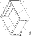
- FIG. 1 and FIG. 2 are diagrams showing an object 20, such as a piece of furniture, according to an embodiment of the present invention.
- the object 20 is a drawer, but the present invention is not limited thereto.
- the object 20 comprises a panel 22 (such as a front plate, but the present invention is not limited thereto), a rear plate 24, a first side wall 26 (such as a left wall), a second side wall 28 (such as a right wall) and a bottom plate 30 together defining an accommodating space S.
- the panel 22 and the first side wall 26 (or the second side wall 28) form a furniture assembly.
- the panel 22 is configured to be connected to the first side wall 26 (or the second side wall 28) through at least one coupling device.
- the panel 22 is connected to the first side wall 26 and the second side wall 28 through a first coupling device 32 and a second coupling device 34 respectively.
- the first coupling device 32 and the second coupling device 34 are respectively arranged on a first side S1 and a second side S2 of the panel 22, and the first coupling device 32 and the second coupling device 34 are configured to be mounted to portions adjacent to front parts f of the first side wall 26 and the second side wall 28 respectively.
- the second coupling device 34 is configured to be connected to a structural component (not shown in figures) adjacent to the front part f of the second side wall 28.
- a structural component not shown in figures
- the panel 22 is arranged with a supporting base 33 (as shown in FIG. 2 ) configured to be supported by a bottom surface of the bottom plate 30.
- the supporting base 33 has a fixing member 35 configured to be fixed to the bottom surface of the bottom plate 30.
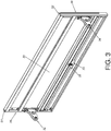
- a first mounting device 36 is arranged adjacent to the first side S1 of the panel 22, and a second mounting device 38 is arranged adjacent to the second side S2 of the panel 22.
- the first mounting device 36 and the second mounting device 38 have substantially identical structural arrangement, and configuration of mounting the first mounting device 36 to the panel 22 is substantially identical to configuration of mounting the second mounting device 38 to the panel 22.
- the panel 22 comprises a first predetermined part 40 and a second predetermined part 42 extended transversely.
- the first predetermined part 40 comprises an extended section 40a and a supporting section 40b.
- the extended section 40a is extended from the panel 22.
- the supporting section 40b is located adjacent to the extended section 40a.
- the extended section 40a is substantially perpendicularly connected to the panel 22, and the supporting section 40b is substantially perpendicularly connected to the extended section 40a to form a lower wall extended toward the second predetermined part 42.
- the second predetermined part 42 is provided with a transversely-extended supporting surface 42a corresponding to the first predetermined part 40.
- the extended section 40a of the first predetermined part 40 of the panel 22 is arranged with a first corresponding feature 48 located adjacent to the second side S2 of the panel 22, and the second predetermined part 42 of the panel 22 is arranged with a second corresponding feature 50 located adjacent to the second side S2 of the panel 22.
- the panel 22 further comprises at least one mounting part, such as a first mounting part 52a, a second mounting part 52b and a third mounting part 52c arranged from a top portion to a bottom portion of the panel 22.
- the mounting parts 52a, 52b, 52c are formed with grooves defined by a plurality of bending sections of the panel 22, and the grooves is communicated with the first side S1 and the second side S2 of the panel 22, but the present invention is not limited thereto.
- each of the mounting devices 36, 38 comprises a mounting member and an auxiliary member.
- the second mounting device 38 comprises a mounting member 54 and an auxiliary member 56 in the present embodiment.
- the mounting member 54 and the auxiliary member 56 are configured to be mounted to the panel 22 in sequence.
- the mounting member 54 is configured to be mounted to the second side S2 of the panel 22 along a direction D.
- the mounting member 54 is arranged with the second coupling device 34, and the second coupling device 34 is longitudinally fixedly connected to the mounting member 54 through at least one connecting feature 57 (such as a rivet or a screw, but the present invention is not limited thereto).
- the mounting member 54 comprises a first supporting part 58 and a second supporting part 60.
- the first supporting part 58 is configured to abut against the first predetermined part 40 of the panel 22.
- the first supporting part 58 is configured to abut against the supporting section 40b of the panel 22 (as shown in FIG. 6 ), but the present invention is not limited thereto.
- the supporting surface 42a of the second predetermined part 42 of the panel 22 is configured to support the second supporting part 60 (as shown in FIG. 6 ).
- the mounting member 54 is configured to be supported on the second side S2 of the panel 22 in advance (as shown in FIG. 6 ), such that the mounting member 54 can be temporarily held on the second side S2 of the panel 22.
- At least one fastening member such as a first fastening member 62a and a second fastening member 62b, are configured to pass through at least one predetermined portion 65 of the mounting member 54 to fixedly connect the mounting member 54 to the second side S2 of the panel 22.
- the first fastening member 62a is configured to fasten the mounting member 54 to the first corresponding feature 48 of the first predetermined part 40 of the panel 22.
- the second fastening member 62b is configured to fasten the mounting member 54 to the second corresponding feature 50 of the second predetermined part 42 of the panel 22.
- the first fastening member 62a is transversely fastened to the first corresponding feature 48
- the second fastening member 62b is transversely fastened to the second corresponding feature 50.
- the mounting member 54 has at least one notch, such as a first notch 64a and a second notch 64b.
- the auxiliary member 56 is configured to be connected to at least one of the mounting member 54 and the panel 22 along the direction D, and the auxiliary member 56 is configured to cover the at least one predetermined portion 65 of the mounting member 54.
- the auxiliary member 56 can cover the at least one predetermined portion 65 of the mounting member 54 and shield the first fastening member 62a and the second fastening member 62b, and the auxiliary member 56 can also cover the entire second side S2 of the panel 22 (please refer to FIG. 2 ), but the present invention is not limited thereto.
- the auxiliary member 56 comprises at least one flexible part, such as a first flexible part 66a and a second flexible part 66b.
- the first flexible part 66a and the second flexible part 66b have substantially identical structural arrangement.
- the first flexible part 66a is illustrated as an example.
- the first flexible part 66a has a first surface K1 and a second surface K2 opposite to the first surface K1.
- the first surface K1 is arranged a buckling section 68 (such as being located at one side of a protruding structure), and the second surface K2 is arranged with at least one holding section 70 (such as a protruding rib, but the present invention is not limited thereto) .
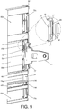
- the buckling section 68 of the first surface K1 is configured to buckle (or hook) a wall surface 69 of the mounting member 54, in order to prevent the auxiliary member 56 from being detached from the mounting member 54 along a direction opposite to the direction D, and the at least one holding section 70 on the second surface K2 of the first flexible part 66a is configured to abut against (or contact) a surface of the panel 22, so as to push and press the auxiliary member 56 to attach tightly between the mounting member 54 and the panel 22 (as shown in FIG. 9 ) .
- the second flexible part 66b is configured to be inserted into the second notch 64b of the mounting member 54. For simplification, no further illustration is provided.
- a guiding feature 71 is arranged at the other side of the protruding structure adjacent to the buckling section 68, in order to guide the wall surface 69 of the mounting member 54 to cross the protruding structure to allow the buckling section 68 to buckle the wall surface 69 of the mounting member 54 (as shown in FIG. 9 ) .
- the guiding feature 71 can be an inclined surface or an arc surface.
- the buckling section 68 and the guiding feature 71 are located at two opposite sides of the protruding structure.
- the auxiliary member 56 is formed with a mounting space 72 (as shown in FIG. 7 ) configured to accommodate the at least one predetermined portion 65 of the mounting member 54.
- the auxiliary member 56 comprises a first wall 74a, a second wall 74b and a third wall 74c connected between the first wall 74a and the second wall 74b, and the mounting space 72 is defined by the first wall 74a, the second wall 74b and the third wall 74c.
- the first flexible part 66a and the second flexible part 66b are arranged on the third wall 74c.
- the auxiliary member 56 further comprises at least one connecting part, such as a first connecting part 76a, a second connecting part 76b and a third connecting part 76c which are arranged from a top portion to a bottom portion of the auxiliary member 56.
- the first connecting part 76a, the second connecting part 76b and the third connecting part 76c are protrusions, and are arranged on the third wall 74c to be correspondingly connected to the first mounting part 52a, the second mounting part 52b and the third mounting part 52c of the panel 22.
- a mounting method for furniture assembly comprises the following steps: providing the mounting member 54 mounted to one side (such as the second side S2) of the panel 22, and the mounting member 54 being arranged with at least one coupling device (such as the second coupling device 34); providing the auxiliary member 56 configured to cover the mounting member 54 and the side of the panel 22; and mounting the panel 22 to a wall (such as the second side wall 28) through the at least one coupling device (such as the second coupling device 34) .
- steps in the mounting method have been illustrated above. For simplification, no further illustration is provided.
- the mounting device and mounting method for furniture assembly is characterized in that:
Landscapes
- Engineering & Computer Science (AREA)
- General Engineering & Computer Science (AREA)
- Mechanical Engineering (AREA)
- Connection Of Plates (AREA)
- Drawers Of Furniture (AREA)
Abstract
Description
- The present invention is related to a mounting device and a mounting method for furniture assembly.
- US patent number
US 9,943,167 B2 rail section 42 substantially perpendicularly connected to each other, and two mounting projections 43a, 43b. The base section 41 of the side covering element 21 has a push-intongue 50 configured to be inserted into the holding rail 23, and another push-in tongue 51 configured to be inserted into the holding bracket 17. Each mounting projection has two clamping jaws 44a, 44b or 45a, 45b. In addition, the two mounting locations 32a, 32b of the drawer panel are configured to receive and install the two mounting projections 43a, 43b. Two fixing screws 57a, 57b are screwed into a space between the two clamping jaws 44a, 44b or 45a, 45b, such that the two clamping jaws 44a, 44b or 45a, 45b are relatively moved to abut against inner sides of the two mounting locations 32a, 32b respectively, so as to achieve clamping installation. However, such installation may directly expose the fixing screws 57a, 57b (as shown inFIG. 1 of the case) on the inner surface of the drawer panel, which is not good for appearance and easy to damp. On the other hand, if the fixing screws 57a, 57b are not tightly fastened or are loosened, the two clamping jaws 44a, 44b or 45a, 45b may not provide sufficient clamping force, such that the stability of the side covering element 21 being installed on the side of the drawer panel is affected. - Therefore, for different market requirements, it is important to develop various products which are more reliable in installation operation.
- This in mind, the present invention aims at providing a mounting device and a mounting method for furniture assembly.
- This is achieved by a furniture assembly according to
claim 1, a mounting device according to claim 11, and a mounting method for furniture assembly according to claim 15. The dependent claims pertain to corresponding further developments and improvements. - As will be seen more clearly from the detailed description following below, the claimed furniture assembly comprises a panel, a mounting member and at least one fastening member. The panel comprises a first predetermined part and a second predetermined part. The first predetermined part comprises an extended section and a supporting section. The extended section is extended from the panel. The supporting section is located adjacent to the extended section. The mounting member is configured to be mounted to the panel. The mounting member comprises a first supporting part and a second supporting part. The first supporting part is configured to abut against the supporting section of the first predetermined part of the panel. The second predetermined part of the panel has a supporting surface configured to support the second supporting part. The at least one fastening member is configured to connect the mounting member to the panel.
- As will be seen more clearly from the detailed description following below, the claimed mounting device comprises a mounting member and an auxiliary member. The mounting member configured to be mounted to one side of a panel. The mounting member is arranged with at least one coupling device configured to connect the panel to a wall of an object. The auxiliary member is configured to cover at least one predetermined portion of the mounting member.
- As will be seen more clearly from the detailed description following below, the claimed mounting method for furniture assembly comprises providing a mounting member mounted to one side of a panel of a furniture assembly, wherein the mounting member is arranged with at least one coupling device; providing an auxiliary member configured to cover the mounting member and the side of the panel; and mounting the panel to a wall of the furniture assembly through the at least one coupling device.
- In the following, the invention is further illustrated by way of example, taking reference to the accompanying drawings thereof:
-
FIG. 1 is a diagram showing an object according to an embodiment of the present invention; -
FIG. 2 is exploded view of a panel and a main body of the object according to an embodiment of the present invention; -
FIG. 3 is a diagram showing two sides of the panel being arranged with mounting devices respectively according to an embodiment of the present invention; -
FIG. 4 is an exploded view of the panel and the mounting device according to an embodiment of the present invention; -
FIG. 5 is an exploded view of the panel and a mounting member of the mounting device according to an embodiment of the present invention; -
FIG. 6 is a diagram showing the mounting member being connected to the panel through at least one fastening member according to an embodiment of the present invention; -
FIG. 7 is an exploded view of the panel connected with the mounting member and an auxiliary member of the mounting device from a first viewing angle according to an embodiment of the present invention; -
FIG. 8 is an exploded view of the panel connected with the mounting member and the auxiliary member of the mounting device from a second viewing angle according to an embodiment of the present invention; and -
FIG. 9 is a diagram showing the panel connected with the mounting member and the auxiliary member of the mounting device being mounted to each other from the second viewing angle according to an embodiment of the present invention. -
FIG. 1 andFIG. 2 are diagrams showing anobject 20, such as a piece of furniture, according to an embodiment of the present invention. In the present embodiment, theobject 20 is a drawer, but the present invention is not limited thereto. Specifically, theobject 20 comprises a panel 22 (such as a front plate, but the present invention is not limited thereto), arear plate 24, a first side wall 26 (such as a left wall), a second side wall 28 (such as a right wall) and abottom plate 30 together defining an accommodating space S. Thepanel 22 and the first side wall 26 (or the second side wall 28) form a furniture assembly. Furthermore, thepanel 22 is configured to be connected to the first side wall 26 (or the second side wall 28) through at least one coupling device. In the present embodiment, thepanel 22 is connected to thefirst side wall 26 and thesecond side wall 28 through afirst coupling device 32 and asecond coupling device 34 respectively. Thefirst coupling device 32 and thesecond coupling device 34 are respectively arranged on a first side S1 and a second side S2 of thepanel 22, and thefirst coupling device 32 and thesecond coupling device 34 are configured to be mounted to portions adjacent to front parts f of thefirst side wall 26 and thesecond side wall 28 respectively. For example, thesecond coupling device 34 is configured to be connected to a structural component (not shown in figures) adjacent to the front part f of thesecond side wall 28. Such configuration is well known to those skilled in the art. For simplification, no further illustration is provided. Moreover, thepanel 22 is arranged with a supporting base 33 (as shown inFIG. 2 ) configured to be supported by a bottom surface of thebottom plate 30. Preferably, the supportingbase 33 has afixing member 35 configured to be fixed to the bottom surface of thebottom plate 30. - As shown in
FIG. 3 andFIG. 4 , afirst mounting device 36 is arranged adjacent to the first side S1 of thepanel 22, and asecond mounting device 38 is arranged adjacent to the second side S2 of thepanel 22. Thefirst mounting device 36 and thesecond mounting device 38 have substantially identical structural arrangement, and configuration of mounting thefirst mounting device 36 to thepanel 22 is substantially identical to configuration of mounting thesecond mounting device 38 to thepanel 22. - As shown in
FIG. 4 ,FIG. 5 andFIG. 6 , thepanel 22 comprises a firstpredetermined part 40 and a secondpredetermined part 42 extended transversely. The firstpredetermined part 40 comprises an extendedsection 40a and a supportingsection 40b. Theextended section 40a is extended from thepanel 22. The supportingsection 40b is located adjacent to theextended section 40a. - Preferably, the
extended section 40a is substantially perpendicularly connected to thepanel 22, and the supportingsection 40b is substantially perpendicularly connected to theextended section 40a to form a lower wall extended toward the secondpredetermined part 42. - Preferably, the second
predetermined part 42 is provided with a transversely-extended supportingsurface 42a corresponding to the firstpredetermined part 40. - Preferably, the
extended section 40a of the firstpredetermined part 40 of thepanel 22 is arranged with a firstcorresponding feature 48 located adjacent to the second side S2 of thepanel 22, and the secondpredetermined part 42 of thepanel 22 is arranged with a secondcorresponding feature 50 located adjacent to the second side S2 of thepanel 22. - Preferably, the
panel 22 further comprises at least one mounting part, such as a first mountingpart 52a, a second mountingpart 52b and a third mountingpart 52c arranged from a top portion to a bottom portion of thepanel 22. In the present invention, the mountingparts panel 22, and the grooves is communicated with the first side S1 and the second side S2 of thepanel 22, but the present invention is not limited thereto. - Furthermore, each of the mounting
devices second mounting device 38 comprises a mountingmember 54 and anauxiliary member 56 in the present embodiment. Preferably, the mountingmember 54 and theauxiliary member 56 are configured to be mounted to thepanel 22 in sequence. - For example, the mounting
member 54 is configured to be mounted to the second side S2 of thepanel 22 along a direction D. The mountingmember 54 is arranged with thesecond coupling device 34, and thesecond coupling device 34 is longitudinally fixedly connected to the mountingmember 54 through at least one connecting feature 57 (such as a rivet or a screw, but the present invention is not limited thereto). The mountingmember 54 comprises a first supportingpart 58 and a second supportingpart 60. The first supportingpart 58 is configured to abut against the firstpredetermined part 40 of thepanel 22. In the present embodiment, the first supportingpart 58 is configured to abut against the supportingsection 40b of the panel 22 (as shown inFIG. 6 ), but the present invention is not limited thereto. On the other hand, the supportingsurface 42a of the secondpredetermined part 42 of thepanel 22 is configured to support the second supporting part 60 (as shown inFIG. 6 ). According to such arrangement, the mountingmember 54 is configured to be supported on the second side S2 of thepanel 22 in advance (as shown inFIG. 6 ), such that the mountingmember 54 can be temporarily held on the second side S2 of thepanel 22. - As shown in
FIG. 6 andFIG. 7 , after the mountingmember 54 is supported on the second side S2 of thepanel 22 in advance, at least one fastening member, such as afirst fastening member 62a and asecond fastening member 62b, are configured to pass through at least onepredetermined portion 65 of the mountingmember 54 to fixedly connect the mountingmember 54 to the second side S2 of thepanel 22. Moreover, thefirst fastening member 62a is configured to fasten the mountingmember 54 to the firstcorresponding feature 48 of the firstpredetermined part 40 of thepanel 22. Similarly, thesecond fastening member 62b is configured to fasten the mountingmember 54 to the secondcorresponding feature 50 of the secondpredetermined part 42 of thepanel 22. - Preferably, the
first fastening member 62a is transversely fastened to the firstcorresponding feature 48, and thesecond fastening member 62b is transversely fastened to the secondcorresponding feature 50. - Preferably, the mounting
member 54 has at least one notch, such as afirst notch 64a and asecond notch 64b. - As shown in
FIG. 7 ,FIG. 8 andFIG. 9 , after the mountingmember 54 is mounted to thepanel 22, theauxiliary member 56 is configured to be connected to at least one of the mountingmember 54 and thepanel 22 along the direction D, and theauxiliary member 56 is configured to cover the at least onepredetermined portion 65 of the mountingmember 54. In the present embodiment, after the mountingmember 54 is mounted to thepanel 22, theauxiliary member 56 can cover the at least onepredetermined portion 65 of the mountingmember 54 and shield thefirst fastening member 62a and thesecond fastening member 62b, and theauxiliary member 56 can also cover the entire second side S2 of the panel 22 (please refer toFIG. 2 ), but the present invention is not limited thereto. - The
auxiliary member 56 comprises at least one flexible part, such as a firstflexible part 66a and a secondflexible part 66b. The firstflexible part 66a and the secondflexible part 66b have substantially identical structural arrangement. In the present embodiment, the firstflexible part 66a is illustrated as an example. Moreover, the firstflexible part 66a has a first surface K1 and a second surface K2 opposite to the first surface K1. The first surface K1 is arranged a buckling section 68 (such as being located at one side of a protruding structure), and the second surface K2 is arranged with at least one holding section 70 (such as a protruding rib, but the present invention is not limited thereto) . After the firstflexible part 66a is inserted into thefirst notch 64a of the mountingmember 54 along the direction D (as shown inFIG. 8 andFIG. 9 ), the bucklingsection 68 of the first surface K1 is configured to buckle (or hook) awall surface 69 of the mountingmember 54, in order to prevent theauxiliary member 56 from being detached from the mountingmember 54 along a direction opposite to the direction D, and the at least one holdingsection 70 on the second surface K2 of the firstflexible part 66a is configured to abut against (or contact) a surface of thepanel 22, so as to push and press theauxiliary member 56 to attach tightly between the mountingmember 54 and the panel 22 (as shown inFIG. 9 ) . Similarly, the secondflexible part 66b is configured to be inserted into thesecond notch 64b of the mountingmember 54. For simplification, no further illustration is provided. - Preferably, a guiding
feature 71 is arranged at the other side of the protruding structure adjacent to the bucklingsection 68, in order to guide thewall surface 69 of the mountingmember 54 to cross the protruding structure to allow the bucklingsection 68 to buckle thewall surface 69 of the mounting member 54 (as shown inFIG. 9 ) . The guidingfeature 71 can be an inclined surface or an arc surface. Preferably, the bucklingsection 68 and the guidingfeature 71 are located at two opposite sides of the protruding structure. - Preferably, the
auxiliary member 56 is formed with a mounting space 72 (as shown inFIG. 7 ) configured to accommodate the at least onepredetermined portion 65 of the mountingmember 54. For example, theauxiliary member 56 comprises afirst wall 74a, asecond wall 74b and athird wall 74c connected between thefirst wall 74a and thesecond wall 74b, and the mountingspace 72 is defined by thefirst wall 74a, thesecond wall 74b and thethird wall 74c. The firstflexible part 66a and the secondflexible part 66b are arranged on thethird wall 74c. - Preferably, the
auxiliary member 56 further comprises at least one connecting part, such as a first connectingpart 76a, a second connectingpart 76b and a third connectingpart 76c which are arranged from a top portion to a bottom portion of theauxiliary member 56. In the present embodiment, the first connectingpart 76a, the second connectingpart 76b and the third connectingpart 76c are protrusions, and are arranged on thethird wall 74c to be correspondingly connected to the first mountingpart 52a, the second mountingpart 52b and the third mountingpart 52c of thepanel 22. - According to an embodiment of the present invention, a mounting method for furniture assembly comprises the following steps: providing the mounting
member 54 mounted to one side (such as the second side S2) of thepanel 22, and the mountingmember 54 being arranged with at least one coupling device (such as the second coupling device 34); providing theauxiliary member 56 configured to cover the mountingmember 54 and the side of thepanel 22; and mounting thepanel 22 to a wall (such as the second side wall 28) through the at least one coupling device (such as the second coupling device 34) . Such steps in the mounting method have been illustrated above. For simplification, no further illustration is provided. - Therefore, the mounting device and mounting method for furniture assembly according to the embodiments of the present invention is characterized in that:
- 1. The first supporting
part 58 of the mountingmember 54 is configured to abut against the firstpredetermined part 40 of thepanel 22, and the second supportingpart 60 of the mountingmember 54 is configured to be supported by the secondpredetermined part 42 of thepanel 22. According to such arrangement, the mountingmember 54 can be temporarily held on one side (such as the first side S1 or the second side S2) of thepanel 22, so as to assist in connecting (such as fixedly connecting) the mountingmember 54 to thepanel 22 through the at least one fastening member (such as thefirst fastening member 62a). - 2. The
auxiliary member 56 is configured to be connected to at least one of the mountingmember 54 and thepanel 22, and theauxiliary member 56 is configured to cover the at least onepredetermined portion 65 of the mountingmember 54. Preferably, theauxiliary member 56 can also cover the side (such as the first side S1 or the second side S2) of thepanel 22. Accordingly, theauxiliary member 56 can provide protecting effect to the mountingmember 54, and theauxiliary member 56 can also be used as a decorative cover for the side of thepanel 22. - 3. The mounting
member 54 is transversely connected to the side (such as the first side S1 or the second side S2) of thepanel 22 through the at least one fastening member. - 4. The
first fastening member 62a and thesecond fastening member 62b are not exposed from an inner side of thepanel 22 of the drawer.
Claims (15)
- A furniture assembly, comprising:a panel (22) comprising a first predetermined part (40) and a second predetermined part (42), wherein the first predetermined part (40) comprises an extended section (40a) and a supporting section (40b), the extended section (40a) is extended from the panel (22), and the supporting section (40b) is located adjacent to the extended section (40a);characterized by:a mounting member (54) configured to be mounted to the panel (22), the mounting member (54) comprising a first supporting part (58) and a second supporting part (60), wherein the first supporting part (58) is configured to abut against the supporting section (40b) of the first predetermined part (40) of the panel (22), and the second predetermined part (42) of the panel (22) has a supporting surface (42a) configured to support the second supporting part (60); andat least one fastening member configured to connect the mounting member (54) to the panel (22).
- The furniture assembly of claim 1, characterized in that the at least one fastening member comprises a first fastening member (62a), and the extended section (40a) of the first predetermined part (40) of the panel (22) is arranged with a first corresponding feature (48) configured to fasten the first fastening member (62a) to one side of the panel (22); wherein the first fastening member (62a) is transversely fastened to the first corresponding feature (48) .
- The furniture assembly of claim 2, characterized in that the at least one fastening member further comprises a second fastening member (62b), and the second predetermined part (42) of the panel (22) is arranged with a second corresponding feature (50) configured to fasten the second fastening member (62b) to the side of the panel (22); wherein the second fastening member (62b) is transversely fastened to the second corresponding feature (50).
- The furniture assembly of claim 2, further characterized by a furniture side wall (26, 28) and at least one coupling device (32, 34) longitudinally connected to the mounting member (54), wherein the at least one coupling device (32, 34) is configured to connect the panel (22) to the furniture side wall (26, 28).
- The furniture assembly of claim 3, characterized in that the supporting surface (42a) of the second predetermined part (42) is transversely arranged on the panel (22).
- The furniture assembly of any of claims 1-5, further characterized by an auxiliary member (56) configured to be connected to at least one of the mounting member (54) and the panel (22), wherein the auxiliary member (56) and the mounting member (54) form a mounting device (36, 38), the auxiliary member (56) comprises at least one flexible part (66a, 66b) having a first surface, and the first surface is arranged with a buckling section (68) configured to buckle the mounting member (54).
- The furniture assembly of claim 6, characterized in that the at least one flexible part (66a, 66b) further has a second surface opposite to the first surface, and the second surface is arranged with a holding section (70) configured to abut against the panel (22) .
- The furniture assembly of claim 6 or 7, characterized in that the auxiliary member (56) is formed with a mounting space (72) configured to accommodate at least one predetermined portion (65) of the mounting member (54).
- The furniture assembly of claim 8, characterized in that the auxiliary member (56) comprises a plurality of walls (74a, 74b, 74c) defining the mounting space (72), and the at lease one flexible part (66a, 66b) is arranged on one of the walls (74a, 74b, 74c) .
- The furniture assembly of claim 9, characterized in that the panel (22) further comprises at least one mounting part, and the auxiliary member (56) further comprises at least one connecting part configured to be correspondingly connected to the at least one mounting part.
- A mounting device (36, 38), characterized by:a mounting member (54) configured to be mounted to one side of a panel (22), the mounting member (54) being arranged with at least one coupling device (32, 34) configured to connect the panel (22) to a wall (26, 28) of an object; andan auxiliary member (56) configured to cover at least one predetermined portion (65) of the mounting member (54).
- The mounting device of claim 11, characterized in that the mounting member (54) comprises a first supporting part (58) and a second supporting part (60), the first supporting part (58) is configured to abut against a first predetermined part (40) of the panel (22), and the second supporting part (60) is configured to be supported by a second predetermined part (42) of the panel (22); wherein the mounting member (54) is transversely connected to the side of the panel (22) through at least one fastening member.
- The mounting device of claim 12, characterized in that the at least one fastening member comprises a first fastening member (62a) and a second fastening member (62b), and the panel (22) is arranged with a first corresponding feature (48) configured to fasten the first fastening member (62a) to the panel (22), and a second corresponding feature (50) configured to fasten the second fastening member (62b) to the panel (22).
- The mounting device of any of claims 11-13, characterized in that the auxiliary member (56) comprises a flexible part (66a, 66b) having a first surface, and the first surface is arranged with a buckling section (68) configured to buckle the mounting member (54); wherein the auxiliary member (56) is formed with a mounting space (72) configured to accommodate the at least one predetermined portion (65) of the mounting member (54).
- A mounting method for furniture assembly, the furniture assembly comprising a panel (22) and a wall (26, 28), and the mounting method characterized by:providing a mounting member (54) mounted to one side of the panel (22), wherein the mounting member (54) is arranged with at least one coupling device (32, 34);providing an auxiliary member (56) configured to cover the mounting member (54) and the side of the panel (22); andmounting the panel (22) to the wall (26, 28) through the at least one coupling device (32, 34).
Applications Claiming Priority (1)
| Application Number | Priority Date | Filing Date | Title |
|---|---|---|---|
| TW109106364A TWI712381B (en) | 2020-02-25 | 2020-02-25 | Mounting device and mounting method for furniture assembly |
Publications (2)
| Publication Number | Publication Date |
|---|---|
| EP3871561A1 true EP3871561A1 (en) | 2021-09-01 |
| EP3871561B1 EP3871561B1 (en) | 2023-07-12 |
Family
ID=72050693
Family Applications (1)
| Application Number | Title | Priority Date | Filing Date |
|---|---|---|---|
| EP20190640.1A Active EP3871561B1 (en) | 2020-02-25 | 2020-08-12 | Furniture assembly with a mounting device and mounting method thereof |
Country Status (4)
| Country | Link |
|---|---|
| US (1) | US11452376B2 (en) |
| EP (1) | EP3871561B1 (en) |
| JP (1) | JP7012129B2 (en) |
| TW (1) | TWI712381B (en) |
Cited By (1)
| Publication number | Priority date | Publication date | Assignee | Title |
|---|---|---|---|---|
| WO2025093304A1 (en) * | 2023-10-31 | 2025-05-08 | Paul Hettich Gmbh & Co. Kg | Panel support |
Families Citing this family (1)
| Publication number | Priority date | Publication date | Assignee | Title |
|---|---|---|---|---|
| TWI843468B (en) * | 2023-03-06 | 2024-05-21 | 川湖科技股份有限公司 | Furniture and furniture assembly thereof |
Citations (3)
| Publication number | Priority date | Publication date | Assignee | Title |
|---|---|---|---|---|
| WO2009111807A2 (en) * | 2008-03-10 | 2009-09-17 | Julius Blum Gmbh | Drawer having a fastening device for wall elements |
| US20130154463A1 (en) * | 2010-05-31 | 2013-06-20 | Grass Gmbh | Connecting device and drawer having a connecting device |
| US20160095435A1 (en) * | 2014-10-02 | 2016-04-07 | Grass Gmbh | Trim Profile Covering Fixture |
Family Cites Families (29)
| Publication number | Priority date | Publication date | Assignee | Title |
|---|---|---|---|---|
| US4042288A (en) * | 1972-12-08 | 1977-08-16 | L. B. (Plastics) Limited | Extruded plastic panel drawers |
| US3926491A (en) * | 1974-04-17 | 1975-12-16 | Philip A Greer | Knock-down drawer assembly |
| DE2426723C3 (en) * | 1974-06-01 | 1978-04-20 | Hans-Werner 4830 Guetersloh Duepree | Foldable corner connector with foil hinge for board-shaped components |
| GB1507498A (en) * | 1975-05-30 | 1978-04-12 | Swish Prod | Structural elements |
| US4162114A (en) * | 1977-04-26 | 1979-07-24 | L. B. (Plastics) Limited | Drawers and drawer components |
| JPS6252449U (en) * | 1985-09-18 | 1987-04-01 | ||
| DE3931155A1 (en) * | 1989-09-19 | 1991-03-28 | Lautenschlaeger Kg Karl | FASTENING ARRANGEMENT FOR DRAWER FRONT PANELS |
| AT398265B (en) * | 1990-01-22 | 1994-11-25 | Blum Gmbh Julius | FASTENING DEVICE FOR THE FRONT PANEL OF A DRAWER |
| DE4305074A1 (en) * | 1993-02-19 | 1994-08-25 | Lautenschlaeger Mepla Werke | Fastening fitting for drawer front panels |
| AT404666B (en) * | 1995-10-30 | 1999-01-25 | Blum Gmbh Julius | DRAWER |
| DE59801908D1 (en) * | 1997-03-03 | 2001-12-06 | Blum Gmbh Julius | Fastening fitting and drawer with such a fitting |
| US5813738A (en) * | 1997-06-20 | 1998-09-29 | Cheng; Wen Sen | Furniture combination |
| US6474901B1 (en) * | 1999-12-28 | 2002-11-05 | Lee Thurston | Modular dovetail joint |
| US6631875B1 (en) * | 2000-09-26 | 2003-10-14 | Adc Telecommunications, Inc. | Cable trough with separate side elements |
| JP4729004B2 (en) * | 2007-06-18 | 2011-07-20 | 榎本金属株式会社 | Decorative plate mounting structure |
| AT505432B1 (en) * | 2007-07-11 | 2012-08-15 | Blum Gmbh Julius | DRAWER WITH A FASTENING DEVICE FOR A FRONT PANEL |
| JP5465110B2 (en) * | 2010-07-05 | 2014-04-09 | 株式会社Lixil | Drawer and drawer front plate adjuster |
| AT511906B1 (en) * | 2011-08-30 | 2016-05-15 | Blum Gmbh Julius | DRAWER |
| AT511905B1 (en) * | 2011-08-30 | 2014-08-15 | Blum Gmbh Julius | DRAWER |
| AT512236B1 (en) * | 2011-11-22 | 2015-10-15 | Blum Gmbh Julius | FASTENING DEVICE FOR FASTENING A FRONT PANEL TO A DRAWER |
| IL231941A (en) * | 2014-04-03 | 2015-07-30 | Oren Sitton | Printable bendable sheets, constructions comprising them and methods of making same |
| TWI539915B (en) * | 2015-11-12 | 2016-07-01 | 川湖科技股份有限公司 | Drawer parts and mounting fitting thereof |
| US10638856B2 (en) * | 2017-01-05 | 2020-05-05 | Fasteners For Retail, Inc. | Retail merchandise tray and display incorporating same |
| CN207754869U (en) * | 2017-06-26 | 2018-08-24 | 广东库博精密科技有限公司 | A kind of drawer glass side board group dress connection structure |
| AT520788B1 (en) * | 2017-12-21 | 2023-03-15 | Blum Gmbh Julius | drawer arrangement |
| AT520636B1 (en) * | 2018-01-26 | 2019-06-15 | Blum Gmbh Julius | Front panel for a drawer |
| US11161673B2 (en) * | 2018-06-29 | 2021-11-02 | James L. Wines | System and method for the storage and protection of priceless works of art |
| CN109296602A (en) * | 2018-11-30 | 2019-02-01 | 广东东泰五金精密制造有限公司 | A front panel assembly structure of a furniture drawer |
| TWI698199B (en) * | 2019-05-15 | 2020-07-11 | 川湖科技股份有限公司 | Drawer and furniture fittings thereof |
-
2020
- 2020-02-25 TW TW109106364A patent/TWI712381B/en active
- 2020-07-14 US US16/928,304 patent/US11452376B2/en active Active
- 2020-08-12 EP EP20190640.1A patent/EP3871561B1/en active Active
- 2020-09-03 JP JP2020148029A patent/JP7012129B2/en active Active
Patent Citations (4)
| Publication number | Priority date | Publication date | Assignee | Title |
|---|---|---|---|---|
| WO2009111807A2 (en) * | 2008-03-10 | 2009-09-17 | Julius Blum Gmbh | Drawer having a fastening device for wall elements |
| US20130154463A1 (en) * | 2010-05-31 | 2013-06-20 | Grass Gmbh | Connecting device and drawer having a connecting device |
| US20160095435A1 (en) * | 2014-10-02 | 2016-04-07 | Grass Gmbh | Trim Profile Covering Fixture |
| US9943167B2 (en) | 2014-10-02 | 2018-04-17 | Grass Gmbh | Trim profile covering fixture |
Cited By (1)
| Publication number | Priority date | Publication date | Assignee | Title |
|---|---|---|---|---|
| WO2025093304A1 (en) * | 2023-10-31 | 2025-05-08 | Paul Hettich Gmbh & Co. Kg | Panel support |
Also Published As
| Publication number | Publication date |
|---|---|
| US20210259418A1 (en) | 2021-08-26 |
| TWI712381B (en) | 2020-12-11 |
| US11452376B2 (en) | 2022-09-27 |
| TW202131828A (en) | 2021-09-01 |
| JP2021133233A (en) | 2021-09-13 |
| EP3871561B1 (en) | 2023-07-12 |
| JP7012129B2 (en) | 2022-01-27 |
Similar Documents
| Publication | Publication Date | Title |
|---|---|---|
| US12372200B2 (en) | Mounting bracket for electrical boxes | |
| US9653901B2 (en) | Holding component for vehicle | |
| EP3871561B1 (en) | Furniture assembly with a mounting device and mounting method thereof | |
| US7735785B2 (en) | Bracket for mounting radio or other instrument in automotive vehicle instrument panel | |
| US20190059585A1 (en) | Slide Rail Assembly and Slide Rail Mechanism Thereof | |
| WO2021004660A1 (en) | Telescoping box support | |
| EP3708031B1 (en) | Connecting device | |
| WO2021044054A1 (en) | Electrical component enclosures for recessed mounting | |
| US12327660B2 (en) | Grommet | |
| US6082873A (en) | Connecting accessory for fluorescent lamps | |
| JP2023137925A (en) | display device | |
| CN113331612B (en) | Mounting device and mounting method for furniture components | |
| KR20230046386A (en) | Partition assembly | |
| JPS6012798B2 (en) | Mounting structure of electronic equipment | |
| JP5329897B2 (en) | Panel support structure | |
| CN108791098B (en) | Mounting structure for mounting display device to display device unit for vehicle | |
| US20210013684A1 (en) | Contact carrier for providing electrical contact for wiring in a vehicle | |
| US12592551B2 (en) | Multi-range cable clip | |
| CN109076711B (en) | Vehicle mount and unit made by assembling the box to the vehicle mount | |
| KR960006404Y1 (en) | Card holder fixing device in computer cabinet | |
| JP7527224B2 (en) | Support device, support structure, and method for installing equipment | |
| JP2000039525A (en) | Splice shelf | |
| JP3027576B1 (en) | Vehicle interior panel mounting structure | |
| JP4621181B2 (en) | Connecting structure of goods shelf equipment | |
| US9066440B2 (en) | Side bracket |
Legal Events
| Date | Code | Title | Description |
|---|---|---|---|
| PUAI | Public reference made under article 153(3) epc to a published international application that has entered the european phase |
Free format text: ORIGINAL CODE: 0009012 |
|
| STAA | Information on the status of an ep patent application or granted ep patent |
Free format text: STATUS: EXAMINATION IS IN PROGRESS |
|
| 17P | Request for examination filed |
Effective date: 20210113 |
|
| AK | Designated contracting states |
Kind code of ref document: A1 Designated state(s): AL AT BE BG CH CY CZ DE DK EE ES FI FR GB GR HR HU IE IS IT LI LT LU LV MC MK MT NL NO PL PT RO RS SE SI SK SM TR |
|
| GRAP | Despatch of communication of intention to grant a patent |
Free format text: ORIGINAL CODE: EPIDOSNIGR1 |
|
| STAA | Information on the status of an ep patent application or granted ep patent |
Free format text: STATUS: GRANT OF PATENT IS INTENDED |
|
| INTG | Intention to grant announced |
Effective date: 20230417 |
|
| GRAS | Grant fee paid |
Free format text: ORIGINAL CODE: EPIDOSNIGR3 |
|
| GRAA | (expected) grant |
Free format text: ORIGINAL CODE: 0009210 |
|
| STAA | Information on the status of an ep patent application or granted ep patent |
Free format text: STATUS: THE PATENT HAS BEEN GRANTED |
|
| AK | Designated contracting states |
Kind code of ref document: B1 Designated state(s): AL AT BE BG CH CY CZ DE DK EE ES FI FR GB GR HR HU IE IS IT LI LT LU LV MC MK MT NL NO PL PT RO RS SE SI SK SM TR |
|
| REG | Reference to a national code |
Ref country code: CH Ref legal event code: EP |
|
| REG | Reference to a national code |
Ref country code: IE Ref legal event code: FG4D |
|
| REG | Reference to a national code |
Ref country code: DE Ref legal event code: R096 Ref document number: 602020013556 Country of ref document: DE |
|
| REG | Reference to a national code |
Ref country code: LT Ref legal event code: MG9D |
|
| REG | Reference to a national code |
Ref country code: NL Ref legal event code: MP Effective date: 20230712 |
|
| REG | Reference to a national code |
Ref country code: AT Ref legal event code: MK05 Ref document number: 1586138 Country of ref document: AT Kind code of ref document: T Effective date: 20230712 |
|
| PG25 | Lapsed in a contracting state [announced via postgrant information from national office to epo] |
Ref country code: NL Free format text: LAPSE BECAUSE OF FAILURE TO SUBMIT A TRANSLATION OF THE DESCRIPTION OR TO PAY THE FEE WITHIN THE PRESCRIBED TIME-LIMIT Effective date: 20230712 |
|
| PG25 | Lapsed in a contracting state [announced via postgrant information from national office to epo] |
Ref country code: GR Free format text: LAPSE BECAUSE OF FAILURE TO SUBMIT A TRANSLATION OF THE DESCRIPTION OR TO PAY THE FEE WITHIN THE PRESCRIBED TIME-LIMIT Effective date: 20231013 |
|
| PG25 | Lapsed in a contracting state [announced via postgrant information from national office to epo] |
Ref country code: ES Free format text: LAPSE BECAUSE OF FAILURE TO SUBMIT A TRANSLATION OF THE DESCRIPTION OR TO PAY THE FEE WITHIN THE PRESCRIBED TIME-LIMIT Effective date: 20230712 |
|
| PG25 | Lapsed in a contracting state [announced via postgrant information from national office to epo] |
Ref country code: IS Free format text: LAPSE BECAUSE OF FAILURE TO SUBMIT A TRANSLATION OF THE DESCRIPTION OR TO PAY THE FEE WITHIN THE PRESCRIBED TIME-LIMIT Effective date: 20231112 |
|
| PG25 | Lapsed in a contracting state [announced via postgrant information from national office to epo] |
Ref country code: SE Free format text: LAPSE BECAUSE OF FAILURE TO SUBMIT A TRANSLATION OF THE DESCRIPTION OR TO PAY THE FEE WITHIN THE PRESCRIBED TIME-LIMIT Effective date: 20230712 Ref country code: RS Free format text: LAPSE BECAUSE OF FAILURE TO SUBMIT A TRANSLATION OF THE DESCRIPTION OR TO PAY THE FEE WITHIN THE PRESCRIBED TIME-LIMIT Effective date: 20230712 Ref country code: PT Free format text: LAPSE BECAUSE OF FAILURE TO SUBMIT A TRANSLATION OF THE DESCRIPTION OR TO PAY THE FEE WITHIN THE PRESCRIBED TIME-LIMIT Effective date: 20231113 Ref country code: NO Free format text: LAPSE BECAUSE OF FAILURE TO SUBMIT A TRANSLATION OF THE DESCRIPTION OR TO PAY THE FEE WITHIN THE PRESCRIBED TIME-LIMIT Effective date: 20231012 Ref country code: LV Free format text: LAPSE BECAUSE OF FAILURE TO SUBMIT A TRANSLATION OF THE DESCRIPTION OR TO PAY THE FEE WITHIN THE PRESCRIBED TIME-LIMIT Effective date: 20230712 Ref country code: LT Free format text: LAPSE BECAUSE OF FAILURE TO SUBMIT A TRANSLATION OF THE DESCRIPTION OR TO PAY THE FEE WITHIN THE PRESCRIBED TIME-LIMIT Effective date: 20230712 Ref country code: IS Free format text: LAPSE BECAUSE OF FAILURE TO SUBMIT A TRANSLATION OF THE DESCRIPTION OR TO PAY THE FEE WITHIN THE PRESCRIBED TIME-LIMIT Effective date: 20231112 Ref country code: HR Free format text: LAPSE BECAUSE OF FAILURE TO SUBMIT A TRANSLATION OF THE DESCRIPTION OR TO PAY THE FEE WITHIN THE PRESCRIBED TIME-LIMIT Effective date: 20230712 Ref country code: GR Free format text: LAPSE BECAUSE OF FAILURE TO SUBMIT A TRANSLATION OF THE DESCRIPTION OR TO PAY THE FEE WITHIN THE PRESCRIBED TIME-LIMIT Effective date: 20231013 Ref country code: FI Free format text: LAPSE BECAUSE OF FAILURE TO SUBMIT A TRANSLATION OF THE DESCRIPTION OR TO PAY THE FEE WITHIN THE PRESCRIBED TIME-LIMIT Effective date: 20230712 Ref country code: ES Free format text: LAPSE BECAUSE OF FAILURE TO SUBMIT A TRANSLATION OF THE DESCRIPTION OR TO PAY THE FEE WITHIN THE PRESCRIBED TIME-LIMIT Effective date: 20230712 Ref country code: AT Free format text: LAPSE BECAUSE OF FAILURE TO SUBMIT A TRANSLATION OF THE DESCRIPTION OR TO PAY THE FEE WITHIN THE PRESCRIBED TIME-LIMIT Effective date: 20230712 |
|
| PG25 | Lapsed in a contracting state [announced via postgrant information from national office to epo] |
Ref country code: PL Free format text: LAPSE BECAUSE OF FAILURE TO SUBMIT A TRANSLATION OF THE DESCRIPTION OR TO PAY THE FEE WITHIN THE PRESCRIBED TIME-LIMIT Effective date: 20230712 |
|
| REG | Reference to a national code |
Ref country code: CH Ref legal event code: PL |
|
| REG | Reference to a national code |
Ref country code: DE Ref legal event code: R097 Ref document number: 602020013556 Country of ref document: DE |
|
| PG25 | Lapsed in a contracting state [announced via postgrant information from national office to epo] |
Ref country code: LU Free format text: LAPSE BECAUSE OF NON-PAYMENT OF DUE FEES Effective date: 20230812 |
|
| PG25 | Lapsed in a contracting state [announced via postgrant information from national office to epo] |
Ref country code: SM Free format text: LAPSE BECAUSE OF FAILURE TO SUBMIT A TRANSLATION OF THE DESCRIPTION OR TO PAY THE FEE WITHIN THE PRESCRIBED TIME-LIMIT Effective date: 20230712 Ref country code: RO Free format text: LAPSE BECAUSE OF FAILURE TO SUBMIT A TRANSLATION OF THE DESCRIPTION OR TO PAY THE FEE WITHIN THE PRESCRIBED TIME-LIMIT Effective date: 20230712 Ref country code: LU Free format text: LAPSE BECAUSE OF NON-PAYMENT OF DUE FEES Effective date: 20230812 Ref country code: EE Free format text: LAPSE BECAUSE OF FAILURE TO SUBMIT A TRANSLATION OF THE DESCRIPTION OR TO PAY THE FEE WITHIN THE PRESCRIBED TIME-LIMIT Effective date: 20230712 Ref country code: DK Free format text: LAPSE BECAUSE OF FAILURE TO SUBMIT A TRANSLATION OF THE DESCRIPTION OR TO PAY THE FEE WITHIN THE PRESCRIBED TIME-LIMIT Effective date: 20230712 Ref country code: CZ Free format text: LAPSE BECAUSE OF FAILURE TO SUBMIT A TRANSLATION OF THE DESCRIPTION OR TO PAY THE FEE WITHIN THE PRESCRIBED TIME-LIMIT Effective date: 20230712 Ref country code: MC Free format text: LAPSE BECAUSE OF FAILURE TO SUBMIT A TRANSLATION OF THE DESCRIPTION OR TO PAY THE FEE WITHIN THE PRESCRIBED TIME-LIMIT Effective date: 20230712 Ref country code: SK Free format text: LAPSE BECAUSE OF FAILURE TO SUBMIT A TRANSLATION OF THE DESCRIPTION OR TO PAY THE FEE WITHIN THE PRESCRIBED TIME-LIMIT Effective date: 20230712 Ref country code: CH Free format text: LAPSE BECAUSE OF NON-PAYMENT OF DUE FEES Effective date: 20230831 |
|
| REG | Reference to a national code |
Ref country code: BE Ref legal event code: MM Effective date: 20230831 |
|
| PLBE | No opposition filed within time limit |
Free format text: ORIGINAL CODE: 0009261 |
|
| STAA | Information on the status of an ep patent application or granted ep patent |
Free format text: STATUS: NO OPPOSITION FILED WITHIN TIME LIMIT |
|
| PG25 | Lapsed in a contracting state [announced via postgrant information from national office to epo] |
Ref country code: IT Free format text: LAPSE BECAUSE OF FAILURE TO SUBMIT A TRANSLATION OF THE DESCRIPTION OR TO PAY THE FEE WITHIN THE PRESCRIBED TIME-LIMIT Effective date: 20230712 |
|
| 26N | No opposition filed |
Effective date: 20240415 |
|
| PG25 | Lapsed in a contracting state [announced via postgrant information from national office to epo] |
Ref country code: FR Free format text: LAPSE BECAUSE OF NON-PAYMENT OF DUE FEES Effective date: 20230912 Ref country code: SI Free format text: LAPSE BECAUSE OF FAILURE TO SUBMIT A TRANSLATION OF THE DESCRIPTION OR TO PAY THE FEE WITHIN THE PRESCRIBED TIME-LIMIT Effective date: 20230712 |
|
| PG25 | Lapsed in a contracting state [announced via postgrant information from national office to epo] |
Ref country code: BE Free format text: LAPSE BECAUSE OF NON-PAYMENT OF DUE FEES Effective date: 20230831 |
|
| PG25 | Lapsed in a contracting state [announced via postgrant information from national office to epo] |
Ref country code: BG Free format text: LAPSE BECAUSE OF FAILURE TO SUBMIT A TRANSLATION OF THE DESCRIPTION OR TO PAY THE FEE WITHIN THE PRESCRIBED TIME-LIMIT Effective date: 20230712 |
|
| PG25 | Lapsed in a contracting state [announced via postgrant information from national office to epo] |
Ref country code: BG Free format text: LAPSE BECAUSE OF FAILURE TO SUBMIT A TRANSLATION OF THE DESCRIPTION OR TO PAY THE FEE WITHIN THE PRESCRIBED TIME-LIMIT Effective date: 20230712 |
|
| PGFP | Annual fee paid to national office [announced via postgrant information from national office to epo] |
Ref country code: GB Payment date: 20250606 Year of fee payment: 6 |
|
| PG25 | Lapsed in a contracting state [announced via postgrant information from national office to epo] |
Ref country code: CY Free format text: LAPSE BECAUSE OF FAILURE TO SUBMIT A TRANSLATION OF THE DESCRIPTION OR TO PAY THE FEE WITHIN THE PRESCRIBED TIME-LIMIT; INVALID AB INITIO Effective date: 20200812 |
|
| PGFP | Annual fee paid to national office [announced via postgrant information from national office to epo] |
Ref country code: IE Payment date: 20250616 Year of fee payment: 6 |
|
| PG25 | Lapsed in a contracting state [announced via postgrant information from national office to epo] |
Ref country code: HU Free format text: LAPSE BECAUSE OF FAILURE TO SUBMIT A TRANSLATION OF THE DESCRIPTION OR TO PAY THE FEE WITHIN THE PRESCRIBED TIME-LIMIT; INVALID AB INITIO Effective date: 20200812 |
|
| PGFP | Annual fee paid to national office [announced via postgrant information from national office to epo] |
Ref country code: DE Payment date: 20250611 Year of fee payment: 6 |
|
| PG25 | Lapsed in a contracting state [announced via postgrant information from national office to epo] |
Ref country code: TR Free format text: LAPSE BECAUSE OF FAILURE TO SUBMIT A TRANSLATION OF THE DESCRIPTION OR TO PAY THE FEE WITHIN THE PRESCRIBED TIME-LIMIT Effective date: 20230712 |