EP3871507A1 - Deboning apparatus for deboning a ham - Google Patents
Deboning apparatus for deboning a ham Download PDFInfo
- Publication number
- EP3871507A1 EP3871507A1 EP21159466.8A EP21159466A EP3871507A1 EP 3871507 A1 EP3871507 A1 EP 3871507A1 EP 21159466 A EP21159466 A EP 21159466A EP 3871507 A1 EP3871507 A1 EP 3871507A1
- Authority
- EP
- European Patent Office
- Prior art keywords
- ham
- deboning
- zone
- moving
- conveyor belt
- Prior art date
- Legal status (The legal status is an assumption and is not a legal conclusion. Google has not performed a legal analysis and makes no representation as to the accuracy of the status listed.)
- Granted
Links
Images



Classifications
-
- A—HUMAN NECESSITIES
- A22—BUTCHERING; MEAT TREATMENT; PROCESSING POULTRY OR FISH
- A22C—PROCESSING MEAT, POULTRY, OR FISH
- A22C17/00—Other devices for processing meat or bones
- A22C17/004—Devices for deboning meat
-
- A—HUMAN NECESSITIES
- A22—BUTCHERING; MEAT TREATMENT; PROCESSING POULTRY OR FISH
- A22C—PROCESSING MEAT, POULTRY, OR FISH
- A22C18/00—Plants, factories, or the like for processing meat
Definitions
- the invention relates to a deboning apparatus for deboning a ham, in particular for deboning a raw ham.
- hams in particular whole raw hams, are subjected to a deboning operation that consists of removing one or more bones from the ham by a longitudinal incision in order to obtain a ham that is deboned and thus easily sliceable also by electric slicers in addition to specific sharpened knives.
- the rotating blade of the electric slicers and of the sharpened knives could in fact get damaged in contact with one of the bones of the ham.
- the longitudinal incision made to enable one or more bones to be extracted is resewed or pressed.
- the ham can then be placed inside a mould and pressed there through the cooperation of a die and a punch to enable air stored inside the meat to be extracted after removal of one or more bones and to give the ham a desired shape.
- the mould can in fact give the deboned ham the characteristic pear shape.
- the deboned ham can be intended, for example, to be sliced on the counter of a shop or domestically.
- the mould can give the deboned ham a parallelpipedon shape, which is also known by the name of brick.
- the deboned ham is intended to be sliced industrially and packaged in trays in a controlled atmosphere, for example to be distributed to supermarkets.
- the deboning operation is generally performed by hand by an operator, because each ham has its own distinctive features. In fact, the shape, dimensions and arrangements of the bones and the sinews thereof vary from ham to ham.
- the ham is placed vertically with respect to a floor, i.e. with a longitudinal axis thereof substantially perpendicular to the floor, and immobilized at an end near the final part of the leg.
- An operator then performs a substantially vertical cut in the ham that creates an opening in the meat through which it is possible to pull one or more bones out.
- the ham is supplied to, and moved along, a conveying device provided inside a ham processing line, until it reaches near a deboning apparatus in a deboning station of which the femur bone is removed.
- the operator has to move the ham manually from the conveying device to a work surface provided in the deboning station, this work surface being distant also some metres from the conveying device.
- the ham After the ham is rested on the work surface, the ham is immobilized there by clamps fitted so as to be pushed from the work surface upwards, the ham being subjected to extraction of the femur bone.
- the clamps thus obstruct the work surface and are an obstacle to the movement of the ham.
- Extracting the femur bone is rather a complex and laborious operation.
- the operator has to use a deboning knife to make an incision around the head of the femur and a longitudinal cut along the femur bone, starting from the ankle bone to the knee joint.
- the operator still by using a deboning knife, has to remove the rind that covers the joint of the knee and separate the bone from the fibrous parts (comprising for example ligaments, tendons).
- the operator proceeds with the removal by gripping the femur near the ankle bone and pulling the femur forcibly by hand.
- the deboning operation thus involves significant physical effort by the operator.
- the operator thus has to make a significant effort both during movement of the hams and during the operation of deboning the hams themselves.
- GB 2425103 A discloses a work station comprising a work surface for processing meat-based products with a work position on one side and an outlet conveyor on the opposite side.
- a conveying system suspended above the level of the work surface, is positioned next to an end of the work surface in order to take the meat-based products to the work position.
- the portions of usable meat removed from a piece of meat are positioned on an outlet conveyor, maintaining the sequence of the pieces of meat, from which they can be transferred together to a packaging station by a transferring conveyor.
- the work surface is provided with a work conveyor that is tilted downwards away from the conveying system, which is washed and sanitized after each meat-based product has been processed.
- a conveyor for rejects for reject material is provided between the work surface and the outlet conveyor.
- US 5173076 A discloses a thigh deboner for edible parts of animals, like chicken thighs, comprising a series of conveying trays on which the thighs are loaded to be deboned.
- the parts of animals are loaded with the bones of the thighs extending transversely to the moving direction of the conveying trays along a processing path.
- Pusher assemblies each engage an end of the bones of the thighs and urge the bones of the thighs longitudinally through openings formed in stripper disks positioned adjacent to the rear edges of the conveying trays. Whilst the bones of the leg are progressively pushed through the openings of the stripper discs, the bones of the thighs are engaged by the edges of a scraper, which scrape the meat of the thighs from the bones of the thighs.
- One object of the invention is to improve the deboning apparatuses for deboning a ham of known type.
- Another object of the invention is to provide a deboning apparatus for deboning a ham that facilitates the deboning operation and the operations of moving said ham related to the deboning operation so as to avoid or minimize the manual movement of said ham and thus effort by the operator.
- a further object of the invention is to provide a deboning apparatus for deboning a ham that is simple, tough and inexpensive.
- a still further object of the invention is to provide a deboning apparatus for deboning a ham that can be installed easily on a pre-existing ham processing line without any need to make substantial changes to the processing line.
- the deboning apparatus is provided with moving means that enables the ham to be loaded automatically by ham supplying means of a ham processing line to an operating zone of the deboning apparatus where the deboning operation occurs, automated movement of the ham inside the operating zone and automated unloading of the ham from the operating zone to removing means of the ham processing line.
- the deboning apparatus according to the invention is provided with gripping means arranged for immobilizing the ham during the deboning operation that does not obstruct the support surface on which the ham is positioned during the deboning operation.
- the deboning apparatus according to the invention is simple to make and can be installed simply and easily on the pre-existing ham production lines.
- this deboning apparatus is arranged for removing at least one bone from a ham 2 to be deboned, the ham 2 being in particular, a whole raw ham.
- the deboning apparatus 1 is couplable with or insertable into a ham processing line 3 inside which the hams 2 are advanced along an advancement path that traverses a plurality of processing stations in which the hams 2 undergo in succession respective processing before marketing of the hams.
- deboning which consists of removing one or more ham bones 2 by a longitudinal incision in order to obtain a ham that is deboned and thus easily sliceable also by electric slicers in addition to by specific sharpened knives.
- deboning can be performed by "open" technique, as explained better further on in the description.
- the bones that can be removed are also the anchetta and the femur bone of a pig thigh that constitutes each ham 2.
- the deboning apparatus 1 is located on a resting plane 4 ( Figure 3 ), for example a floor of an industrial plant in which the ham processing line 3 is installed.
- the deboning apparatus 1 comprises at least one deboning unit 6 provided with an operating zone 7 in which an operator 8 extracts the bones 2 from the ham to be deboned to obtain a deboned ham.
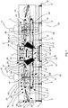
- the deboning unit 6 comprises a frame 12 ( Figure 3 ) provided with support means by which the deboning unit 6 rests on the resting plane 4.
- the support means can comprise a plurality of legs 15 and of feet 5, each foot 5 being connected on one side to a respective leg 15 and on the other side to the resting plane 4.
- the deboning apparatus 1 further comprises supplying means 9 arranged for supplying the ham 2 to be deboned from the ham processing line 3 to an entry zone 10 of the deboning unit 6.
- the entry zone 10 faces on one side the supplying means 9 and on the other side faces the inside of the deboning unit 6.
- the entry zone 10 is thus arranged for receiving the incoming ham 2 to be deboned conveyed by the supplying means 9 so that it can be supplied to the deboning unit 6.
- the supplying means 9 can be associated with, in particular connected, to the frame 12 of the deboning unit 6.
- the hams 2 are conveyed by the supplying means 9 along an advancement direction A.
- the hams 2 are received restingly on a resting area 45 with which the supplying means 9 is provided.
- the deboning apparatus 1 can comprise a plurality of deboning units 6 arranged along the supplying means 9 and on opposite sides of the supplying means 9.
- the deboning apparatus 1 shown in Figure 1 comprises six deboning units 6, fitted on opposite sides of the supplying means 9, i.e. three on the side facing left looking at Figure 1 and three on the side facing right looking at Figure 1 .
- the deboning units 6 fitted on opposite sides of the supplying means 9 can comprise pairs of deboning units 6 fitted in a specular manner with respect to the supplying means 9.
- the deboning units 6 are fitted to only one side of the supplying means 9.
- the number and arrangement of the deboning units 6 inside the deboning apparatus 1 is variable in function of production needs and the space intended for the deboning apparatus 1 inside the processing line 3.
- the deboning apparatus 1 is modular and each deboning unit 6 defines a module of the deboning apparatus 1.
- the supplying means 9 can comprise a conveyor belt having a longitudinal axis L substantially parallel to the advancement direction A.
- the longitudinal axis L can correspond to an axis of symmetry of the deboning apparatus 1.
- the supplying means 9 can be associated with a conveyor of the processing line 3 that conveys the hams 2 through at least one processing station preceding the deboning apparatus 1 in the advancement path of the hams 2 inside the processing line 3.
- the processing station immediately upstream of the deboning apparatus 1 along the advancement path of the hams 2 inside the processing line 3 can be a cutting station C in which the ham 2 to be deboned is partially arranged inside a cutting device 11, immobilized there in a clamp provided in the cutting device 11 and the final part of the leg thereof is cut by a saw with which the cutting device 11 is provided.
- a further operator 80 can simultaneously remove a first bone called the "anchetta".
- the deboning apparatus 1 further comprises a support body 13 ( Figure 5 ) to which the supplying means 9 is fitted.
- the deboning apparatus 1 further comprises at least one stopping and diverting element, which is not shown in the Figures, configured for immobilizing the ham 2 that advances along the advancement direction A and divert the ham 2 towards the desired entry zone 10.
- the at least one stopping and diverting element can be fitted to the support body 13.
- the at least one stopping and diverting element can be connected to the supplying means 9.
- the at least one stopping and diverting element is movable between an engaged position in which it interacts with the ham 2 whilst the latter advances on the supplying means 9 stopping conveying thereof along the advancement direction A and diverting the latter towards the desired deboning unit 6 and a removed position in which, on the other hand, it does not interact with the ham 2 and thus permits continuation along the advancement direction A.
- At least one stopping and diverting element for each entry zone 10 can be provided.
- the at least one stopping and diverting element is shaped as a pusher element, that is movable transversely, i.e. substantially perpendicularly to the advancement direction A, to push the ham 2 to the appropriate deboning unit 6.
- the at least one stopping and diverting element comprises a wall, in particular a wall that is retractable because it is movable vertically, i.e. in a direction that is substantially perpendicular to the resting area 45.
- the wall is further connected to an actuator that enables the wall to be driven transversely, i.e. substantially perpendicularly to the advancement direction A moving from the removed position to the engaged position and thus occupying an area that protrudes beyond the resting area 45, i.e. moving away from the resting plane 4.
- a surface of the wall is intended to contact the ham 2 in use when the actuator takes the wall to the engaged position.
- the at least one stopping and diverting element can have a substantially T-shaped plan conformation, where the head of the T is formed by the wall and the shank by the actuator.
- the first stopping and diverting element faces the second stopping and diverting element.
- the retractable wall of the first stopping and diverting element When the first stopping and diverting element moves transversely, engaging an area that protrudes beyond the resting area 45, i.e. moving away from the resting plane 4, moving from the removed position to the engaged position, the retractable wall of the first stopping and diverting element is taken to the engaged position to be able to interact with the ham 2, whereas the retractable wall of the second stopping and diverting element is moved to descend vertically along a direction substantially perpendicular to the resting plane 4 in the direction approaching the resting plane 4 so as to be arranged below the resting area 45 and thus not interacting with the ham 2 (in other words the retractable wall of the first stopping and diverting element reaches the removed position).
- the second stopping and diverting element is not an obstacle to the passage of the ham 2 from the supplying means 9 to the first deboning unit 6.
- the retractable wall of the second stopping and diverting element is taken to the engaged position to be able to interact with the ham 2
- the retractable wall of the first stopping and diverting element is moved to lower vertically along a direction substantially perpendicular to the resting plane 4 in the direction approaching the resting plane 4 so as to be arranged below the resting area 45 and thus not interacting with the ham 2 (in other words the retractable wall of the first stopping and diverting element reaches the removed position).
- the first stopping and diverting element is not an obstacle to the passage of the ham 2 from the supplying means 9 to the second deboning unit 6.
- the at least one stopping and diverting element is shaped as a vane element, or as a rod, hinged on an end so as to be able to rotate around a rotation axis between the engaged position and the removed position by a set angle of rotation.
- the vane element, or the rod is controlled by an actuator, in particular hydraulic, connected for example to the hinged end of the vane element or of the rod so as to enable a rotation thereof at a rotation angle comprised between 30° and 90°, in particular of about 45°.
- the vane element or the rod In the removed position the vane element or the rod can be arranged substantially parallel to the supplying means 9 and, in particular, near an edge zone of the supplying means 9, so as not to obstruct or obstruct to a limited extent the resting area 45.
- a ham 2 can be advanced by the supplying means 9 to reach the entry zone 10 of the desired deboning unit 6, i.e. in which is requested that the ham 2 be subjected to deboning.
- the vane element or the rod obstructs a part of the resting area 45 such that the ham 2 interacts with the vane element/rod by sliding along a part thereof to reach an area facing the entry zone 10 where it is desired that the ham 2 is transferred whilst the vane element moves from the engaged position to the removed position.
- the engaged position is reached by the rod element or by the vane once it is rotated by the actuator around the rotation axis.
- the deboning unit 6 further comprises moving means 18 arranged for conveying the ham 2 along a moving path provided inside the deboning unit 6.
- the moving means 18 can be supported by the frame 12 of the deboning unit 6.
- the moving means 18 can be associated with, in particular connected to, the support body 13 of the deboning apparatus 1.
- the ham 2 is moved from the supplying means 9 to the moving means 18 owing to the least one stopping and diverting element.
- the deboning unit 6 further comprises an outlet zone 19 for the deboned ham 2 arranged for receiving the incoming ham 2 once it is deboned in the operating zone 7 and transferring the outgoing ham 2 again to the ham processing line 3.
- the outlet zone 19 on one side faces the inside of the deboning unit 6, whilst on the other side the outlet zone 19 faces a removing means 20 arranged for removing the deboned ham 2 from the outlet zone 19 and, then, from the deboning unit 6 and transferring the deboned ham 2 to the ham processing line 3 to be subjected to further processing, such as, for example, skinning.
- the outlet zone 19 is thus arranged for receiving the deboned ham 2 and supplying the deboned ham 2 to the removing means 20.
- the removing means 20 can comprise a conveyor belt.
- the deboning apparatus 1 comprises a plurality of deboning units 6, such deboning units 6 are fitted to both sides of the supplying means 9 and of the removing means 20.
- the longitudinal axes of the removing means 20 and the longitudinal axes L of the supplying means 9 can belong to respective planes substantially perpendicular to the resting plane 4.
- the moving means 18 can be arranged substantially perpendicular to the supplying means 9 and to the removing means 20.
- the removing means 20 is fitted to the frame 12 of the deboning apparatus 1.
- the supplying means 9 can be fitted to the frame 12, in particular to the support body 13, near the entry zone 10 and the moving means 18 can be associated with the frame 12, in particular with the support body 13, both near the entry zone 10 and near the outlet zone 9.
- the moving means 18 moves the ham 2 along a first moving direction D1, shown with an arrow in Figure 3 , and along a second moving direction D2, which is also shown with an arrow in Figure 3 , the second moving direction D2 being substantially parallel to and opposite the first moving direction D1.
- first moving direction D1 and the second moving direction D2 are substantially perpendicular to the advancement direction A.
- the entry zone 10 and the outlet zone 19 act as passage zones of the hams 2 respectively entering and exiting the deboning unit 6, inasmuch as they are arranged respectively for receiving the hams 2 to be deboned supplied to the deboning unit 6 by the supplying means 9 and supplyinng the deboned hams 2 in the operating zone 7, from the deboning unit 6 to the removing means 20.
- the entry zone 10 is arranged at a greater height than the outlet zone 19 with respect to the resting plane 4.
- the moving path is C-shaped, in a vertical section. This vertical section is taken along a plane substantially perpendicular to the resting plane 4 and substantially perpendicular to the advancement direction A.
- the operating zone 7 is interposed between the entry zone 10 and the outlet zone 19 along the moving path and, in particular, downstream of the entry zone 10 and upstream of the outlet zone 19 along the moving path of the hams 2 inside the deboning unit 6.
- the operating zone 7 is arranged substantially at the same height as the entry zone 10 with respect to the resting plane 4.
- the hams 2 are then conveyed by the moving means 18 along the moving path between the entry zone 10 and the outlet zone 19, passing through the operating zone 7, so as to supply the ham 2 to be deboned to the operating zone 7 and remove the deboned ham 2 from the operating zone 7.
- the moving means 18 defines a rest surface 21 for the ham 2 along the moving path of the ham 2 inside the deboning unit 6.
- the moving means 18 can comprise a first conveying device 22 arranged at a first height A1 with respect to the resting plane 4, and to second conveying device 23 arranged at a second height A2 with respect to the resting plane 4, in which the first height A1 is greater than the second height A2.
- the first height A1 and the second height A2 show the distances from the resting plane 4 respectively of the rest surface 21 defined by the first conveying device 22 and of the rest surface 21 defined by the second conveying device 23.
- the entry zone 10 is obtained, in particular, near an end of the first conveying device 22 and the outlet zone 19 is obtained, in particular, near an end of the second conveying device 23.
- the ham 2 to be deboned is advanced by the first conveying device 22 along the first moving direction D1, whilst the deboned ham 2 is advanced by the second conveying device 23 along the second moving direction D2.
- the first conveying device 22 defines a first portion of the moving path comprising a first leg of the C and the second conveying device 23 defines a second portion of the moving path comprising a second leg of the C, said first portion and said second portion being substantially parallel.
- the ham 2 is advanced along the first moving direction D1 whilst along the second portion the ham 2 is advanced along the second moving direction D2.
- the rest surface 21 of the moving means 18 comprises the rest surfaces of the first conveying device 22 and of the second conveying device 23.
- the supplying means 9 and the first conveying device 22 can be so fitted, in particular, that the rest surface 21 of the first conveying device 22 and the resting area 45 for the ham 2 defined by the supplying means 9 are substantially coplanar. In this manner the ham 2 can easily be transferred from the resting area 45 to the rest surface 21 of the first conveying device 22 by means of the interaction of the ham 2 with the at least one stopping and diverting element 14 driven by the actuator.
- the first conveying device 22 can comprise at least two belt conveyors, i.e. a first conveyor belt 24 and a second conveyor belt 25 arranged in sequence along the first moving direction D1 such that the rest surface 21 that, in this case is formed by the respective rest surfaces of the two conveyor belts, is substantially parallel to the resting plane 4.
- the entry zone 10 is obtained in the conveyor belt nearer the supplying means 9, for example the second conveyor belt 25.
- the first conveying device 22 comprises the first conveyor belt 24, the second conveyor belt 25 and a third conveyor belt 26, arranged in succession and so fitted that the rest surface 21 of the moving means 18, which in this case is formed by the respective outer rest surfaces of the three conveyor belts 24, 25, 26, is substantially parallel to the resting plane 4.
- the first conveyor belt 24 is arranged downstream of the second conveyor belt 25 and the second conveyor belt 25 is arranged downstream of the third conveyor belt 26 along the first moving direction D1.
- the second conveyor belt 25 and the third conveyor belt 26 are so fitted that the rest surfaces thereof are reciprocally coplanar and further coplanar with the resting area 45 defined by the supplying means 9.
- the second conveying device 23 comprises only one conveyor belt 27, but another embodiment that is not shown can provide several conveyor belts arranged in sequence along the second moving direction D2 as for the first conveying device 22.
- the second conveying device 23 is so fitted that the rest surface 21 of the moving means 18, which in this case is formed by the outer support surface of the conveyor belt 27, is substantially parallel to the resting plane 4.
- the removing means 20 and the second conveying device 23 can be so fitted in particular that the rest surface 21 of the second conveying device 23 is arranged substantially above a rest face 49 defined by the removing means 20. In this manner the ham 2 can be transferred, in use, from the rest surface 21 to the rest face 49 by the force of gravity.
- the entry zone 10 is obtained in the third conveyor belt 26 and faces the supplying means 9, whilst the outlet zone 19 is obtained in the conveyor belt 27 and faces the removing means 20.
- first conveyor belt 24, the second conveyor belt 25, the third conveyor belt 26 and the conveyor belt 27 are fitted to the frame 12.
- the third conveyor belt 26 and the conveyor belt 27 can be further associated with, in particular connected to, the support body 13, respectively near the entry zone 10 and the outlet zone 19.
- the supplying means 9 can be arranged above the removing means 20 with respect to the resting plane 4.
- Each deboning unit 6 can further comprise a pusher 28 fitted to said frame 12 and arranged in the operating zone 7 so as to slide along a vertical direction V substantially perpendicular to the rest surface 21 alternatively between a non-operating configuration N in which the pusher 28 is retracted and does not extend beyond the rest surface 21 so as not to interact with the ham 2 to be deboned and an operating configuration, not shown in the Figures, in which the pusher 28 exits at least partially from the rest surface 21 so as to push from the bottom upwards the ham 2 to be deboned to promote superior opening thereof and facilitate extracting of at least one bone.
- a pusher 28 fitted to said frame 12 and arranged in the operating zone 7 so as to slide along a vertical direction V substantially perpendicular to the rest surface 21 alternatively between a non-operating configuration N in which the pusher 28 is retracted and does not extend beyond the rest surface 21 so as not to interact with the ham 2 to be deboned and an operating configuration, not shown in the Figures, in which the push
- the pusher 28 is driven, in use, by the operator 8 generally after the latter, by means of the use of a knife, in particular a deboning knife, has made an incision around the head of the femur and a longitudinal cut along the femur bone starting from the ankle bone as far as the joint of the knee of the ham 2 to be deboned.
- a knife in particular a deboning knife
- the pusher 28 can be run, i.e. can move from the non-operating configuration N to the operating configuration, for example, by a pneumatic cylinder, which is not shown in the Figures, drivable by a control that can be arranged, for example, a platform 60 arranged resting on the resting plane 4, on which the operator 8 can rise in the operating zone 7 to perform the deboning operations on the ham 2.
- a control can be arranged, for example, a platform 60 arranged resting on the resting plane 4, on which the operator 8 can rise in the operating zone 7 to perform the deboning operations on the ham 2.
- the control can be driven by a foot of the operator 8, for example by exerting pressure on the control.
- the control is deactivated and the pusher 28 can move from the operating configuration to the non-operating configuration N.
- the pusher 28 can be shaped as a pin.
- a passage 29 is provided between the first conveyor belt 24 and the second conveyor belt 25, this passage 29 being arranged for enabling the transit of the pusher 28, which is driven, in use, between the non-operating configuration N and the operating configuration by the operator 8.
- the moving means 18 of the deboning apparatus 1 further comprise transferring means 30 arranged for transferring the ham 2, once deboned, from the operating zone 7.
- the transferring means 30 transfers the ham 2 along the moving path inside the deboning unit 6 from an upper plane defined by the rest surface 21 of the first conveying device 22 to a lower plane defined by the rest surface 21 of the second conveying device 23, the upper plane being arranged substantially at the height A1 and the lower plane being arranged substantially at the height A2.
- the transferring means 30 is configured so as to define a third portion of the moving path, this third portion comprising a rounded zone of the C that connects the first portion to the second portion of the C.
- the C-shaped conformation of the moving path is permitted by the reciprocal arrangement of the first conveying device 22 (and thus of the entry zone 10), of the second conveying device 23 (and thus of the outlet zone 19) and the transferring means 30.
- the transferring means 30 comprises a tilting moving device 31 rotatable around a rotation axis R, shown with a dashed and dotted line in Figure 2 , and provided with a rest zone 32 intended to supportingly receive the ham 2 immediately after it has been deboned.
- the rest surface 21 of the moving means 18 is also defined by the rest zone 32 of the tilting moving device 31, and also by the rest surfaces of the first conveying device 22 and of the second conveying device 23.
- the tilting moving device 31 is rotatable, in particular, in two opposite directions shown by the arrows with an arched rod of Figure 3 , so as to be able to vary a tilt of the rest zone 32 with respect to the resting plane 4.
- the tilting moving device 31 is rotatable between an upper position S in which an end part 33 of the rest zone 32 is arranged near an end area 34 of the rest surface 21 defined by the first conveying device 22 and a lower second position I (shown by a dashed line in Figure 3 ) in which the end part 33 of the rest zone 32 is arranged near an end area 44 of the rest surface 21 defined by the second conveying device 23.
- the tilting moving device 31 can comprise a conveyor 51 provided with a support structure hinged on a drive shaft that enables the drive shaft to rotate around the rotation axis R.
- the rotation axis R can coincide substantially with the rotation axis of a pulley, for example the drive pulley, with which the conveyor belt is provided.
- the rotation axis R is arranged at a third height A3 with respect to the intermediate resting plane 4 between the first height A1 and the second height A2.
- the rotation axis R can be substantially parallel to the advancement direction A of the ham 2 on the supplying means 9 and substantially perpendicular to the first moving direction D1 and to the second moving direction D2 or, in other words, perpendicular to the direction of motion of the conveyor 51.
- the transferring means 30, instead of the tilting moving device 31, comprises a lifting device, for example a belt lifting device, arranged for transferring the deboned ham 2 from the first conveying device 22 to the second conveying device 23 by moving the deboned ham 2 along a substantially vertical direction, i.e. substantially perpendicular to the conveying device 22 and to the second conveying device 23.
- a lifting device for example a belt lifting device
- the deboning unit 6 of the deboning apparatus 1 can further comprise gripping means 35 fitted to the frame 12 to retain the ham 2 during the deboning operation.
- the gripping means 35 is fitted to the frame 12 so as to be positioned above the rest surface 21 during operation thereof. In this manner, the drive of the gripping means 35 does not obstruct the moving means 18 and, in particular, the rest surface 21, during the deboning operation. Owing to the positioning above the operating zone 7 of the gripping means 35, the movement of the ham 2 inside the operating zone 7 is free, i.e. is not hindered by the gripping means 35.
- the gripping means 35 is provided with a pair of clamps, or jaws, 36a, 36b that are movable towards/away from one another to push the ham 2 to be deboned therebetween and further movable towards and away from the rest surface 21 of the first conveying device 22 so that they can press the ham 2 to be deboned against said rest surface 21. In this manner it is possible to immobilize the ham 2 to be deboned in the operating zone 7 and permit easy extraction of at least one bone by the operator 8.
- the clamps 36a, 36b are provided with a respective engagement surface 37 that can be provided with teeth 46 that protrude from the engagement surface 37 and are intended to interact with a portion of the meat of the ham 2 so as to increase the grip with the latter when the clamps 36a, 36b are driven to immobilize the ham 2 to be deboned against the rest surface 21.
- Each clamp 36a, 36b is connected to the frame 12 for example by a respective support arm 43.
- Each clamp 36a, 36b can be lowered or raised with respect to the rest surface 21 of the first conveying device 22 by driving a respective actuator, in particular linear, for example a hydraulic cylinder connected to the respective support arm 43 of each clamp 36a, 36b.
- a respective actuator in particular linear, for example a hydraulic cylinder connected to the respective support arm 43 of each clamp 36a, 36b.
- Each actuator is driven by the operator 8, for example by pressing a button to which the actuator is connected.
- the actuators are so driven as to move the clamps 36a, 36b towards and away from the rest surface 21 and reciprocally towards and away from one another along respectively a first operating direction O1 and along a second moving direction O2, that are opposite to one another.
- the operating directions O1, O2 are oblique with respect to the first moving direction D1 and to the second moving direction D2. Accordingly, the operating directions O1, O2 cut the rest surface 21 at an angle other than 90°.
- the deboning apparatus 1 can further comprise a collecting station 38 arranged for receiving the ham 2 to be deboned before being supplied in turn to the operating zone 7 by the moving means 18.
- the collecting station 38 can, further, receive one or more further hams 2 so that they can wait in the collecting station 38 whilst a first ham 2 is subjected to deboning in the operating zone 7.
- the collecting station 38 can act as a magazine or store of further hams 2.
- the collecting station 38 is arranged in the deboning unit 6, for example near the entry zone 10 upstream of the operating zone 7. In other words, the collecting station 38 is interposed between the entry zone 10 and the operating zone 7.
- the collecting station 38 is obtained, in particular, in the third conveyor belt 26 when the latter is present.
- the deboning operations of the hams 2 are accelerated because a further ham 2 is already available near the operating zone 7 to be conveyed to the operating zone 7 once a first ham 2 has been deboned and, from the operating zone 7, is transferred to the transferring means 30.
- the deboning apparatus 1 can further comprise, an unloading device 39 arranged for receiving the at least one bone extracted from the ham 2 in the operating zone 7 and a disposal conveyor belt 40 associated with the unloading device 39 and connected to a waste disposal unit to deliver to the latter the at least one bone extracted from the ham 2 so that it can be disposed of, which is not shown in the Figures.
- An unloading device 39 for each deboning unit 6 can be provided.
- the unloading device 39 is fitted to the support body 13 such that a first end 47 of the unloading device 39 is arranged near the operating zone 7. In this manner, the operator 8, in use, can easily lift partially an arm and deposit on the unloading device 39 at least one bone extracted from the ham 2, hardly moving the torso away from the operating zone 7.
- the unloading device 39 further comprises a second end 48, opposite said first end 47, that leads onto the disposal conveyor belt 40 such that the at least one bone falls by the force of gravity.
- the unloading device 39 comprises at least one slide 61 on which the bones slide to lead onto the disposal conveyor belt 40.
- the disposal conveyor belt 40 can be fitted below the rest surface 21.
- the second conveying device 23 and the transferring means 30 are not provided.
- the outlet zone 19 is obtained, in particular, near a further end of the first conveying device 22 opposite the end of the conveying device 22 near which the entry zone 10 is obtained.
- the outlet zone 19 is opposite the entry zone 10 with respect to the operating zone 7.
- the entry zone 10 and the outlet zone 19 are arranged substantially at the same height, i.e. the first height A1.
- the removing means 20 is associated with the moving means 18 near the further end of the first conveying device 22.
- the first conveying device 22 in this embodiment is configured for moving the ham 2 from the operating zone 7 to the removing means 20.
- the removing means 20 and the moving means 18 in this embodiment can be arranged substantially at the same height, i.e. at the first height A1.
- the removing means 20 can be arranged below the first conveying device 22, i.e. at a height from the resting plane 4 less than the first height A1 and the hams 2 fall from the first conveying device 22 and, in particular, from the first conveyor belt 24 if present, by the force of gravity onto the removing means 20.
- the removing means 20 can be arranged substantially perpendicularly to the first conveying device 22, i.e. substantially parallel to the supplying means 9, and can receive the deboned hams 2 exiting each deboning unit 6 arranged on the same side of the supplying means 9.
- the removing means 20 can be provided for each deboning unit 6.
- the moving path of each ham 2 inside each deboning unit 6 in this embodiment is substantially linear.
- the supplying means 9 is arranged near only the entry zone 10.
- a ham 2 to be processed is advanced and supplied to the deboning apparatus 1 by the supplying means 9.
- the cutting station C When the deboning apparatus 1 is inserted into the processing line 3, immediately upstream of the deboning unit 6 the cutting station C is provided in which the final part of the leg of the ham 2, resting for example on conveying means of known type, is arranged by the further operator 80 inside the cutting device 11 and immobilized there in a clamp. The further operator 80 then cuts the final part of the leg by the saw with which the cutting device 11 is provided and cuts a string with which the ham 2 can be provided, having the purpose of enabling the ham 2 to be fixed to a seasoning frame during seasoning.
- the ham 2 is advanced by the supplying means 9 along the advancement direction A until it reaches near the entry zone 10 of a deboning unit 6 that has to be supplied with the ham 2.
- the stopping and diverting element is moved from the removed position to the engaged position.
- the stopping and diverting element comes into contact with the ham 2 and removes the ham 2 from the supplying means 9 and by moving the ham 2 along a direction substantially perpendicular to the advancement direction A to reach an area facing the desired entry zone 10. After this, the stopping and diverting element is returned to the removed position.
- the wall of the stopping and diverting element is associated with the deboning unit 6 that does not have to be supplied by the ham 2, is lowered to enable the ham 2 to be transferred from the supplying means 9 to the desired deboning unit 6.
- the ham 2 is transferred from the supplying means 9 to the first conveying device 22 of the moving means 18 and, in particular, to the entry zone 10.
- Driving the moving means 18 and/or the at least one stopping and diverting element can be performed by a remote controller.
- Sensor means can be associated with the moving means 18, the sensor means being connected to the remote controller, for example via wireless, arranged for detecting the presence of the ham 2 and communicating the presence to the remote controller and consequently driving the moving means 18 and the stopping and diverting element.
- the sensor means can detect the presence of a ham 2 that, conveyed along the advancement direction A by the supplying means 9, reached near the entry zone 10 to which the ham 2 has to be transferred.
- the sensor means can be arranged near each entry zone 10; for example, can be fitted to the support body 13 or to the frame 12.
- the sensor means can detect the presence of a ham 2 arranged in the collecting station 38.
- the sensor means can be arranged, in addition or alternatively to the above, in the collecting station 38, for example connected to the first conveying device 22, in particular to the third conveyor belt 26.
- the sensor means can comprise optical sensor means, for example one or more photocells, and/or can comprise force sensor means, for example one or more load cells, arranged for detecting the presence of a ham 2.
- the one or more photocells and/or the one or more load cells can be arranged diagonally transversely to the advancement direction A.
- a transfer transducer can be provided, for example an encoder, fitted to the supplying means 9 and connected to the remote controller, by means of which it is possible to establish when a ham 2 advancing on the supplying means 9 reaches near the desired entry zone 10.
- the deboning apparatus 1 can further comprise control means connected to the remote controller and drivable by the operator 8 at the end of the deboning operation to send to the remote controller a signal indicating the end of the deboning operation.
- the remote controller can accordingly drive the moving means 18 to evacuate the deboned ham 2 and to advance a further ham 2 to be deboned.
- the control means can be provided with a button.
- the control means can be fitted to the frame 12 so as to be able to be driven by a knee of the operator 8, by a hand of the operator 8 or, also, by both hands of the operator 8.
- the ham 2 to be deboned is then transferred by the first conveying device 22 to the operating zone 7 to be subjected to the deboning operation.
- the moving means 18 In the operating zone 7 the moving means 18 is arrested such that the ham 2 is arranged at the passage 29.
- the operator 8 then drives the gripping means 35.
- the clamps 36a, 36b are driven to move along the first operating direction O1 so that the teeth 46 interact with a portion of the meat of the ham 2 and lock the ham 2 against the rest surface 21.
- the operator 8 then starts the deboning operation by making an incision around the head of the femur and a longitudinal cut and gradually uncovering with the help of the knife the at least one bone to be extracted.
- the operator can drive the pusher 28, by the specific control, to move from the non-operating configuration N to the operating configuration moving upwards along the vertical direction V (i.e. towards the rest surface 21 of the first conveying device 22 and thus to the ham 2) such that the pusher 28 can push the ham 2 from below and promote the extraction of the at least one bone.
- the operator 8 returns the at least one bone to the slide 61 of the unloading device 39 along walls tilted downwards, the at least one bone of the unloading device 39 slides until it reaches the second end 48 of the unloading device 39, after which it falls by the force of gravity onto the disposal conveyor belt 40 below.
- the ham 2 is received from the conveyor belt nearer the supplying means 9 and is moved by the conveyor belt nearer the supplying means 9 along the first moving direction D1 until a further conveyor belt is reached that is arranged downstream of the aforesaid conveyor belt nearer the supplying means 9.
- the movement of the ham 2 continues as set out above if other conveyor belts downstream of those disclosed here are present.
- the ham 2 is first received on the third conveyor belt 26, is then advanced along the first moving direction D1 by the third conveyor belt 26 until it reaches the second conveyor belt 25 on which the ham 2 is transferred, is then advanced again along the first moving direction D1 by the second conveyor belt 25 until it reaches the first conveyor belt 24.
- the second conveyor belt 25 and the first conveyor belt 24 are then arrested and the travel of the ham 2 is immobilized so that the ham 2 is partially received resting on the rest surface 21 of the first conveyor belt 24 and of the second conveyor belt 25. In this manner the ham 2 has a lower surface that faces the passage 29.
- the operator 8 drives the pusher 28 by the specific control to move from the operating configuration to the non-operating configuration N such that the pusher 28 is moved along the vertical direction V downwards, i.e. moving away from the rest surface 21 of the first conveying device 22 and thus from the ham 2.
- the operator 8 further drives the jaws 36a, 36b to move along the second operating direction O2 to move away from the ham 2 and free the ham 2 from the clamp thereof.
- the operator 8 can then drive the control means, when provided, to send to the remote controller a signal indicating the end of the deboning operation.
- the moving means 18 is again driven by the remote controller along the first moving direction D1 so as to convey the ham 2 from the first conveying device 22 (in particular from the first conveyor belt 24 in the embodiment of the Figures) to the transferring means 30.
- the tilting moving device 31 is or is taken to the upper position S and the conveyor 51 is so driven as to receive the ham 2 and remove the ham 2 from the first conveying device 22 so that it is completely resting on the tilting moving device 31.
- the moving means 18 can be moved until a further ham 2 can be conveyed from the collecting station 38 to the operating zone 7. Whilst the further ham 2 is advanced along the moving means 18 to reach the operating zone 7, the operator 8 can sharpen the deboning knife.
- the tilting moving device 31 is rotated around the rotation axis R and moves from the upper position S to the lower position I. During rotation of the tilting moving device 31, the conveyor 51 is not driven. After this, the conveyor 51 is driven so as to move the ham 2 towards the second conveying device 23, which is driven in turn, and thus move the ham 2 from the transferring means 30 to the second conveying device 23. The tilting moving device 31 is then returned to the upper position S to be able to receive and convey a further ham 2.
- the second conveying device 23 then conveys the ham 2 along the second moving direction D2 until it reaches the outlet zone 19 arranged at one end of the second conveying device 23 from which it is unloaded by the force of gravity onto the removing means 20 that conveys the ham 2 to other processing stations of the processing line 3.
- the operation of the deboning apparatus 1 in the alternative embodiment that does not provide the second conveying device 23 and the transferring means 30 is identical to what is illustrated above with reference to the embodiment shown in the Figures, with the difference that the ham 2, once it is deboned in the operating zone 7, is conveyed along the first moving direction D1 until it reaches the outlet zone 19 arranged at the further end of the first conveying device 22 from which it is transferred, or is unloaded by the force of gravity, to the removing means 20 that conveys the ham 2 to other processing stations of the processing line 3.
- the ham 2 is moved inside each deboning unit 6 from the entry zone 10 to the outlet zone 19 without the operator 8 having to move the ham 2. This enables the fatigue to be reduced considerably to which the operator 8 is subjected during the deboning operation.
- conveying each ham 2 inside the deboning unit 6 in which it is processed is automated completely and accordingly each ham 2 is conveyed automatically to the operating zone 7 and is evacuated automatically from the latter owing to the moving means 18.
Landscapes
- Life Sciences & Earth Sciences (AREA)
- Engineering & Computer Science (AREA)
- Wood Science & Technology (AREA)
- Zoology (AREA)
- Food Science & Technology (AREA)
- Meat, Egg Or Seafood Products (AREA)
- Beans For Foods Or Fodder (AREA)
Abstract
Description
- The invention relates to a deboning apparatus for deboning a ham, in particular for deboning a raw ham.
- Submitting a ham to a series of processes before being marketed is known. For example, hams, in particular whole raw hams, are subjected to a deboning operation that consists of removing one or more bones from the ham by a longitudinal incision in order to obtain a ham that is deboned and thus easily sliceable also by electric slicers in addition to specific sharpened knives. The rotating blade of the electric slicers and of the sharpened knives could in fact get damaged in contact with one of the bones of the ham.
- Once the deboning operation has finished, the longitudinal incision made to enable one or more bones to be extracted is resewed or pressed.
- The ham can then be placed inside a mould and pressed there through the cooperation of a die and a punch to enable air stored inside the meat to be extracted after removal of one or more bones and to give the ham a desired shape. The mould can in fact give the deboned ham the characteristic pear shape. In this case, the deboned ham can be intended, for example, to be sliced on the counter of a shop or domestically. Alternatively, the mould can give the deboned ham a parallelpipedon shape, which is also known by the name of brick. In this case, the deboned ham is intended to be sliced industrially and packaged in trays in a controlled atmosphere, for example to be distributed to supermarkets.
- The deboning operation is generally performed by hand by an operator, because each ham has its own distinctive features. In fact, the shape, dimensions and arrangements of the bones and the sinews thereof vary from ham to ham.
- From the prior art, it is known to debone a ham by hand using a technique known as "slipped out". This "slipped out" technique involves the ham being rested on a surface, being immobilized in a clamp until a saw cuts the final part of the leg of the ham and an operator removes a first bone called "anchetta".
- After this, the ham is placed vertically with respect to a floor, i.e. with a longitudinal axis thereof substantially perpendicular to the floor, and immobilized at an end near the final part of the leg. An operator then performs a substantially vertical cut in the ham that creates an opening in the meat through which it is possible to pull one or more bones out.
- From the prior art, deboning a ham by hand using a technique known as "open" technique is known. This "open" technique involves the ham being rested on a surface, being immobilized in a clamp until a saw cuts the final part of the leg of the ham and an operator removes a first bone called the "anchetta".
- After which, the ham is supplied to, and moved along, a conveying device provided inside a ham processing line, until it reaches near a deboning apparatus in a deboning station of which the femur bone is removed. The operator has to move the ham manually from the conveying device to a work surface provided in the deboning station, this work surface being distant also some metres from the conveying device.
- After the ham is rested on the work surface, the ham is immobilized there by clamps fitted so as to be pushed from the work surface upwards, the ham being subjected to extraction of the femur bone. The clamps thus obstruct the work surface and are an obstacle to the movement of the ham.
- Extracting the femur bone is rather a complex and laborious operation. The operator has to use a deboning knife to make an incision around the head of the femur and a longitudinal cut along the femur bone, starting from the ankle bone to the knee joint. Subsequently, the operator, still by using a deboning knife, has to remove the rind that covers the joint of the knee and separate the bone from the fibrous parts (comprising for example ligaments, tendons). Lastly, once the femur bone is partially uncovered, the operator proceeds with the removal by gripping the femur near the ankle bone and pulling the femur forcibly by hand.
- The deboning operation thus involves significant physical effort by the operator.
- After the ham has been deboned, it has to be positioned again on the conveying device, by the hands of the operator. The operations of loading the ham from the conveying device to the work surface and unloading the ham from the work surface to the conveying device are performed manually by the same operator and are repetitive and very tiring because of the significant weight of the raw hams.
- The operator thus has to make a significant effort both during movement of the hams and during the operation of deboning the hams themselves.
-
GB 2425103 A -
US 5173076 A discloses a thigh deboner for edible parts of animals, like chicken thighs, comprising a series of conveying trays on which the thighs are loaded to be deboned. The parts of animals are loaded with the bones of the thighs extending transversely to the moving direction of the conveying trays along a processing path. Pusher assemblies each engage an end of the bones of the thighs and urge the bones of the thighs longitudinally through openings formed in stripper disks positioned adjacent to the rear edges of the conveying trays. Whilst the bones of the leg are progressively pushed through the openings of the stripper discs, the bones of the thighs are engaged by the edges of a scraper, which scrape the meat of the thighs from the bones of the thighs. - One drawback of the deboning apparatuses of known type is that they require a significant effort on the part of the operator, who has to move the hams to be deboned and has to perform the deboning operation.
- One object of the invention is to improve the deboning apparatuses for deboning a ham of known type.
- Another object of the invention is to provide a deboning apparatus for deboning a ham that facilitates the deboning operation and the operations of moving said ham related to the deboning operation so as to avoid or minimize the manual movement of said ham and thus effort by the operator.
- A further object of the invention is to provide a deboning apparatus for deboning a ham that is simple, tough and inexpensive.
- A still further object of the invention is to provide a deboning apparatus for deboning a ham that can be installed easily on a pre-existing ham processing line without any need to make substantial changes to the processing line.
- The aforementioned objects and still others are achieved by a deboning apparatus for deboning a ham according to one or more of the claims set out below.
- Owing to the invention, it is possible to reduce considerably the fatigue to which an operator is subjected who has to move a ham in order to debone the ham. In fact, the deboning apparatus according to the invention is provided with moving means that enables the ham to be loaded automatically by ham supplying means of a ham processing line to an operating zone of the deboning apparatus where the deboning operation occurs, automated movement of the ham inside the operating zone and automated unloading of the ham from the operating zone to removing means of the ham processing line. Further, the deboning apparatus according to the invention is provided with gripping means arranged for immobilizing the ham during the deboning operation that does not obstruct the support surface on which the ham is positioned during the deboning operation.
- The deboning apparatus according to the invention is simple to make and can be installed simply and easily on the pre-existing ham production lines.
- The invention can be better understood and implemented with reference to the attached drawings that illustrate an embodiment thereof by way of non-limiting example, in which:
-
Figure 1 is a top view of a portion of a ham processing line showing a ham deboning apparatus according to the invention included in said ham processing line; -
Figure 2 is an enlarged view of a portion of the deboning apparatus ofFigure 1 showing two deboning stations; -
Figure 3 is a section taken along the plane III-III ofFigure 1 ; -
Figure 4 is an enlarged detail ofFigure 3 showing an operating zone of a deboning unit of the deboning apparatus according to the invention; -
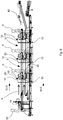
Figure 5 is a section taken along the plane V-V ofFigure 1 . - With reference to the aforesaid Figures, a deboning apparatus according to the invention has been indicated overall by 1, this deboning apparatus is arranged for removing at least one bone from a
ham 2 to be deboned, theham 2 being in particular, a whole raw ham. - The deboning apparatus 1 is couplable with or insertable into a
ham processing line 3 inside which thehams 2 are advanced along an advancement path that traverses a plurality of processing stations in which thehams 2 undergo in succession respective processing before marketing of the hams. - One of the processes that the
hams 2 undergo along theham processing line 3 is deboning, which consists of removing one ormore ham bones 2 by a longitudinal incision in order to obtain a ham that is deboned and thus easily sliceable also by electric slicers in addition to by specific sharpened knives. In particular, deboning can be performed by "open" technique, as explained better further on in the description. For example, the bones that can be removed are also the anchetta and the femur bone of a pig thigh that constitutes eachham 2. - The deboning apparatus 1 is located on a resting plane 4 (
Figure 3 ), for example a floor of an industrial plant in which theham processing line 3 is installed. - The deboning apparatus 1 comprises at least one
deboning unit 6 provided with anoperating zone 7 in which anoperator 8 extracts thebones 2 from the ham to be deboned to obtain a deboned ham. - The
deboning unit 6 comprises a frame 12 (Figure 3 ) provided with support means by which thedeboning unit 6 rests on the resting plane 4. The support means can comprise a plurality oflegs 15 and offeet 5, eachfoot 5 being connected on one side to arespective leg 15 and on the other side to the resting plane 4. - With particular reference to
Figure 2 that shows an enlarged portion P of the deboning apparatus 1 ofFigure 1 , the deboning apparatus 1 further comprisessupplying means 9 arranged for supplying theham 2 to be deboned from theham processing line 3 to anentry zone 10 of thedeboning unit 6. Theentry zone 10 faces on one side the supplyingmeans 9 and on the other side faces the inside of thedeboning unit 6. - The
entry zone 10 is thus arranged for receiving theincoming ham 2 to be deboned conveyed by the supplyingmeans 9 so that it can be supplied to thedeboning unit 6. - The supplying means 9 can be associated with, in particular connected, to the
frame 12 of thedeboning unit 6. - The
hams 2 are conveyed by the supplyingmeans 9 along an advancement direction A. In particular, thehams 2 are received restingly on a restingarea 45 with which the supplyingmeans 9 is provided. - The deboning apparatus 1 can comprise a plurality of
deboning units 6 arranged along the supplyingmeans 9 and on opposite sides of the supplyingmeans 9. - For example, the deboning apparatus 1 shown in
Figure 1 comprises sixdeboning units 6, fitted on opposite sides of the supplyingmeans 9, i.e. three on the side facing left looking atFigure 1 and three on the side facing right looking atFigure 1 . - The
deboning units 6 fitted on opposite sides of the supplyingmeans 9 can comprise pairs ofdeboning units 6 fitted in a specular manner with respect to the supplyingmeans 9. - In one embodiment, the
deboning units 6 are fitted to only one side of the supplyingmeans 9. - The number and arrangement of the
deboning units 6 inside the deboning apparatus 1 is variable in function of production needs and the space intended for the deboning apparatus 1 inside theprocessing line 3. In other words, the deboning apparatus 1 is modular and eachdeboning unit 6 defines a module of the deboning apparatus 1. - The supplying means 9 can comprise a conveyor belt having a longitudinal axis L substantially parallel to the advancement direction A. The longitudinal axis L can correspond to an axis of symmetry of the deboning apparatus 1.
- The supplying means 9 can be associated with a conveyor of the
processing line 3 that conveys thehams 2 through at least one processing station preceding the deboning apparatus 1 in the advancement path of thehams 2 inside theprocessing line 3. For example, the processing station immediately upstream of the deboning apparatus 1 along the advancement path of thehams 2 inside theprocessing line 3 can be a cutting station C in which theham 2 to be deboned is partially arranged inside a cuttingdevice 11, immobilized there in a clamp provided in thecutting device 11 and the final part of the leg thereof is cut by a saw with which thecutting device 11 is provided. Afurther operator 80 can simultaneously remove a first bone called the "anchetta". - The deboning apparatus 1 further comprises a support body 13 (
Figure 5 ) to which the supplyingmeans 9 is fitted. - The deboning apparatus 1 further comprises at least one stopping and diverting element, which is not shown in the Figures, configured for immobilizing the
ham 2 that advances along the advancement direction A and divert theham 2 towards the desiredentry zone 10. - The at least one stopping and diverting element can be fitted to the
support body 13. In particular, the at least one stopping and diverting element can be connected to the supplyingmeans 9. - The at least one stopping and diverting element is movable between an engaged position in which it interacts with the
ham 2 whilst the latter advances on the supplyingmeans 9 stopping conveying thereof along the advancement direction A and diverting the latter towards the desireddeboning unit 6 and a removed position in which, on the other hand, it does not interact with theham 2 and thus permits continuation along the advancement direction A. - At least one stopping and diverting element for each
entry zone 10 can be provided. - In one embodiment, the at least one stopping and diverting element is shaped as a pusher element, that is movable transversely, i.e. substantially perpendicularly to the advancement direction A, to push the
ham 2 to theappropriate deboning unit 6. - The at least one stopping and diverting element comprises a wall, in particular a wall that is retractable because it is movable vertically, i.e. in a direction that is substantially perpendicular to the resting
area 45. The wall is further connected to an actuator that enables the wall to be driven transversely, i.e. substantially perpendicularly to the advancement direction A moving from the removed position to the engaged position and thus occupying an area that protrudes beyond the restingarea 45, i.e. moving away from the resting plane 4. A surface of the wall is intended to contact theham 2 in use when the actuator takes the wall to the engaged position. - The at least one stopping and diverting element can have a substantially T-shaped plan conformation, where the head of the T is formed by the wall and the shank by the actuator.
- When a first stopping and diverting element for a
first deboning unit 6 and a second stopping and diverting element is provided for asecond deboning unit 6 opposite thefirst deboning unit 6 is provided, the first stopping and diverting element faces the second stopping and diverting element. - When the first stopping and diverting element moves transversely, engaging an area that protrudes beyond the resting
area 45, i.e. moving away from the resting plane 4, moving from the removed position to the engaged position, the retractable wall of the first stopping and diverting element is taken to the engaged position to be able to interact with theham 2, whereas the retractable wall of the second stopping and diverting element is moved to descend vertically along a direction substantially perpendicular to the resting plane 4 in the direction approaching the resting plane 4 so as to be arranged below the restingarea 45 and thus not interacting with the ham 2 (in other words the retractable wall of the first stopping and diverting element reaches the removed position). In this manner, the second stopping and diverting element is not an obstacle to the passage of theham 2 from the supplyingmeans 9 to thefirst deboning unit 6. On the other hand, when the second stopping and diverting element moves transversely engaging an area that protrudes beyond the restingarea 45, the retractable wall of the second stopping and diverting element is taken to the engaged position to be able to interact with theham 2, whilst the retractable wall of the first stopping and diverting element is moved to lower vertically along a direction substantially perpendicular to the resting plane 4 in the direction approaching the resting plane 4 so as to be arranged below the restingarea 45 and thus not interacting with the ham 2 (in other words the retractable wall of the first stopping and diverting element reaches the removed position). In this manner, the first stopping and diverting element is not an obstacle to the passage of theham 2 from the supplyingmeans 9 to thesecond deboning unit 6. - In another embodiment, the at least one stopping and diverting element is shaped as a vane element, or as a rod, hinged on an end so as to be able to rotate around a rotation axis between the engaged position and the removed position by a set angle of rotation. The vane element, or the rod, is controlled by an actuator, in particular hydraulic, connected for example to the hinged end of the vane element or of the rod so as to enable a rotation thereof at a rotation angle comprised between 30° and 90°, in particular of about 45°. In the removed position the vane element or the rod can be arranged substantially parallel to the supplying
means 9 and, in particular, near an edge zone of the supplyingmeans 9, so as not to obstruct or obstruct to a limited extent the restingarea 45. In this manner, aham 2 can be advanced by the supplyingmeans 9 to reach theentry zone 10 of the desireddeboning unit 6, i.e. in which is requested that theham 2 be subjected to deboning. In the engaged position, on the other hand, the vane element or the rod obstructs a part of the restingarea 45 such that theham 2 interacts with the vane element/rod by sliding along a part thereof to reach an area facing theentry zone 10 where it is desired that theham 2 is transferred whilst the vane element moves from the engaged position to the removed position. The engaged position is reached by the rod element or by the vane once it is rotated by the actuator around the rotation axis. - The
deboning unit 6 further comprises moving means 18 arranged for conveying theham 2 along a moving path provided inside thedeboning unit 6. - The moving means 18 can be supported by the
frame 12 of thedeboning unit 6. - The moving means 18 can be associated with, in particular connected to, the
support body 13 of the deboning apparatus 1. - The
ham 2 is moved from the supplyingmeans 9 to the moving means 18 owing to the least one stopping and diverting element. - The
deboning unit 6 further comprises anoutlet zone 19 for the debonedham 2 arranged for receiving theincoming ham 2 once it is deboned in theoperating zone 7 and transferring theoutgoing ham 2 again to theham processing line 3. - In the embodiment illustrated in the Figures, the
outlet zone 19 on one side faces the inside of thedeboning unit 6, whilst on the other side theoutlet zone 19 faces a removingmeans 20 arranged for removing the debonedham 2 from theoutlet zone 19 and, then, from thedeboning unit 6 and transferring the debonedham 2 to theham processing line 3 to be subjected to further processing, such as, for example, skinning. - The
outlet zone 19 is thus arranged for receiving the debonedham 2 and supplying the debonedham 2 to the removingmeans 20. - The removing means 20 can comprise a conveyor belt. When the deboning apparatus 1 comprises a plurality of
deboning units 6,such deboning units 6 are fitted to both sides of the supplyingmeans 9 and of the removingmeans 20. The longitudinal axes of the removingmeans 20 and the longitudinal axes L of the supplyingmeans 9 can belong to respective planes substantially perpendicular to the resting plane 4. - The moving means 18 can be arranged substantially perpendicular to the supplying
means 9 and to the removingmeans 20. - The removing means 20 is fitted to the
frame 12 of the deboning apparatus 1. - The supplying means 9 can be fitted to the
frame 12, in particular to thesupport body 13, near theentry zone 10 and the moving means 18 can be associated with theframe 12, in particular with thesupport body 13, both near theentry zone 10 and near theoutlet zone 9. - In use, the moving means 18 moves the
ham 2 along a first moving direction D1, shown with an arrow inFigure 3 , and along a second moving direction D2, which is also shown with an arrow inFigure 3 , the second moving direction D2 being substantially parallel to and opposite the first moving direction D1. - In particular, the first moving direction D1 and the second moving direction D2 are substantially perpendicular to the advancement direction A.
- The
entry zone 10 and theoutlet zone 19 act as passage zones of thehams 2 respectively entering and exiting thedeboning unit 6, inasmuch as they are arranged respectively for receiving thehams 2 to be deboned supplied to thedeboning unit 6 by the supplyingmeans 9 and supplyinng the debonedhams 2 in theoperating zone 7, from thedeboning unit 6 to the removingmeans 20. - The
entry zone 10 is arranged at a greater height than theoutlet zone 19 with respect to the resting plane 4. - The moving means 18, in use, conveys the
ham 2 inside thedeboning unit 6 from theentry zone 10 to theoutlet zone 19 along the moving path. - In the embodiment of the deboning apparatus 1 illustrated in the Figures, the moving path is C-shaped, in a vertical section. This vertical section is taken along a plane substantially perpendicular to the resting plane 4 and substantially perpendicular to the advancement direction A.
- The
operating zone 7 is interposed between theentry zone 10 and theoutlet zone 19 along the moving path and, in particular, downstream of theentry zone 10 and upstream of theoutlet zone 19 along the moving path of thehams 2 inside thedeboning unit 6. - The
operating zone 7 is arranged substantially at the same height as theentry zone 10 with respect to the resting plane 4. - In the
deboning unit 6, thehams 2 are then conveyed by the moving means 18 along the moving path between theentry zone 10 and theoutlet zone 19, passing through theoperating zone 7, so as to supply theham 2 to be deboned to theoperating zone 7 and remove the debonedham 2 from theoperating zone 7. - The moving means 18 defines a
rest surface 21 for theham 2 along the moving path of theham 2 inside thedeboning unit 6. - With reference in particular to
Figure 3 , the moving means 18 can comprise a first conveyingdevice 22 arranged at a first height A1 with respect to the resting plane 4, and to second conveyingdevice 23 arranged at a second height A2 with respect to the resting plane 4, in which the first height A1 is greater than the second height A2. - The first height A1 and the second height A2 show the distances from the resting plane 4 respectively of the
rest surface 21 defined by the first conveyingdevice 22 and of therest surface 21 defined by the second conveyingdevice 23. - The
entry zone 10 is obtained, in particular, near an end of the first conveyingdevice 22 and theoutlet zone 19 is obtained, in particular, near an end of the second conveyingdevice 23. - The
ham 2 to be deboned is advanced by the first conveyingdevice 22 along the first moving direction D1, whilst the debonedham 2 is advanced by the second conveyingdevice 23 along the second moving direction D2. - The first conveying
device 22 defines a first portion of the moving path comprising a first leg of the C and the second conveyingdevice 23 defines a second portion of the moving path comprising a second leg of the C, said first portion and said second portion being substantially parallel. Along the first portion, theham 2 is advanced along the first moving direction D1 whilst along the second portion theham 2 is advanced along the second moving direction D2. - The
rest surface 21 of the movingmeans 18 comprises the rest surfaces of the first conveyingdevice 22 and of the second conveyingdevice 23. - The supplying means 9 and the first conveying
device 22 can be so fitted, in particular, that therest surface 21 of the first conveyingdevice 22 and the restingarea 45 for theham 2 defined by the supplyingmeans 9 are substantially coplanar. In this manner theham 2 can easily be transferred from the restingarea 45 to therest surface 21 of the first conveyingdevice 22 by means of the interaction of theham 2 with the at least one stopping and diverting element 14 driven by the actuator. - The first conveying
device 22 can comprise at least two belt conveyors, i.e. afirst conveyor belt 24 and asecond conveyor belt 25 arranged in sequence along the first moving direction D1 such that therest surface 21 that, in this case is formed by the respective rest surfaces of the two conveyor belts, is substantially parallel to the resting plane 4. - When the first conveying
device 22 comprises two belt conveyors, theentry zone 10 is obtained in the conveyor belt nearer the supplyingmeans 9, for example thesecond conveyor belt 25. - In the embodiment illustrated in the Figures, the first conveying
device 22 comprises thefirst conveyor belt 24, thesecond conveyor belt 25 and athird conveyor belt 26, arranged in succession and so fitted that therest surface 21 of the moving means 18, which in this case is formed by the respective outer rest surfaces of the threeconveyor belts first conveyor belt 24 is arranged downstream of thesecond conveyor belt 25 and thesecond conveyor belt 25 is arranged downstream of thethird conveyor belt 26 along the first moving direction D1. - The
second conveyor belt 25 and thethird conveyor belt 26 are so fitted that the rest surfaces thereof are reciprocally coplanar and further coplanar with the restingarea 45 defined by the supplyingmeans 9. - Still in the embodiment illustrated in the Figures, the second conveying
device 23 comprises only oneconveyor belt 27, but another embodiment that is not shown can provide several conveyor belts arranged in sequence along the second moving direction D2 as for the first conveyingdevice 22. - Also the second conveying
device 23 is so fitted that therest surface 21 of the moving means 18, which in this case is formed by the outer support surface of theconveyor belt 27, is substantially parallel to the resting plane 4. - The removing means 20 and the second conveying
device 23 can be so fitted in particular that therest surface 21 of the second conveyingdevice 23 is arranged substantially above arest face 49 defined by the removingmeans 20. In this manner theham 2 can be transferred, in use, from therest surface 21 to therest face 49 by the force of gravity. - In the case of the embodiment illustrated in the Figures, the
entry zone 10 is obtained in thethird conveyor belt 26 and faces the supplyingmeans 9, whilst theoutlet zone 19 is obtained in theconveyor belt 27 and faces the removingmeans 20. - Still in the embodiment illustrated in the Figures, the
first conveyor belt 24, thesecond conveyor belt 25, thethird conveyor belt 26 and theconveyor belt 27 are fitted to theframe 12. - The
third conveyor belt 26 and theconveyor belt 27 can be further associated with, in particular connected to, thesupport body 13, respectively near theentry zone 10 and theoutlet zone 19. - The supplying means 9 can be arranged above the removing means 20 with respect to the resting plane 4.
- Each
deboning unit 6 can further comprise apusher 28 fitted to saidframe 12 and arranged in theoperating zone 7 so as to slide along a vertical direction V substantially perpendicular to therest surface 21 alternatively between a non-operating configuration N in which thepusher 28 is retracted and does not extend beyond therest surface 21 so as not to interact with theham 2 to be deboned and an operating configuration, not shown in the Figures, in which thepusher 28 exits at least partially from therest surface 21 so as to push from the bottom upwards theham 2 to be deboned to promote superior opening thereof and facilitate extracting of at least one bone. - The
pusher 28 is driven, in use, by theoperator 8 generally after the latter, by means of the use of a knife, in particular a deboning knife, has made an incision around the head of the femur and a longitudinal cut along the femur bone starting from the ankle bone as far as the joint of the knee of theham 2 to be deboned. - The
pusher 28 can be run, i.e. can move from the non-operating configuration N to the operating configuration, for example, by a pneumatic cylinder, which is not shown in the Figures, drivable by a control that can be arranged, for example, aplatform 60 arranged resting on the resting plane 4, on which theoperator 8 can rise in theoperating zone 7 to perform the deboning operations on theham 2. In this manner, the control can be driven by a foot of theoperator 8, for example by exerting pressure on the control. By releasing the pressure on the control, the control is deactivated and thepusher 28 can move from the operating configuration to the non-operating configuration N. - The
pusher 28 can be shaped as a pin. - With reference in particular to
Figure 4 that shows an enlarged detail T ofFigure 3 , apassage 29 is provided between thefirst conveyor belt 24 and thesecond conveyor belt 25, thispassage 29 being arranged for enabling the transit of thepusher 28, which is driven, in use, between the non-operating configuration N and the operating configuration by theoperator 8. - The moving means 18 of the deboning apparatus 1 further comprise transferring means 30 arranged for transferring the
ham 2, once deboned, from theoperating zone 7. - In particular, the transferring means 30 transfers the
ham 2 along the moving path inside thedeboning unit 6 from an upper plane defined by therest surface 21 of the first conveyingdevice 22 to a lower plane defined by therest surface 21 of the second conveyingdevice 23, the upper plane being arranged substantially at the height A1 and the lower plane being arranged substantially at the height A2. - The transferring means 30 is configured so as to define a third portion of the moving path, this third portion comprising a rounded zone of the C that connects the first portion to the second portion of the C.
- The C-shaped conformation of the moving path is permitted by the reciprocal arrangement of the first conveying device 22 (and thus of the entry zone 10), of the second conveying device 23 (and thus of the outlet zone 19) and the transferring means 30.
- In the embodiment illustrated in the Figures, the transferring means 30 comprises a
tilting moving device 31 rotatable around a rotation axis R, shown with a dashed and dotted line inFigure 2 , and provided with arest zone 32 intended to supportingly receive theham 2 immediately after it has been deboned. - The
rest surface 21 of the movingmeans 18 is also defined by therest zone 32 of thetilting moving device 31, and also by the rest surfaces of the first conveyingdevice 22 and of the second conveyingdevice 23. - The tilting moving
device 31 is rotatable, in particular, in two opposite directions shown by the arrows with an arched rod ofFigure 3 , so as to be able to vary a tilt of therest zone 32 with respect to the resting plane 4. In particular, the tilting movingdevice 31 is rotatable between an upper position S in which anend part 33 of therest zone 32 is arranged near anend area 34 of therest surface 21 defined by the first conveyingdevice 22 and a lower second position I (shown by a dashed line inFigure 3 ) in which theend part 33 of therest zone 32 is arranged near anend area 44 of therest surface 21 defined by the second conveyingdevice 23. - The tilting moving
device 31 can comprise aconveyor 51 provided with a support structure hinged on a drive shaft that enables the drive shaft to rotate around the rotation axis R. - The rotation axis R can coincide substantially with the rotation axis of a pulley, for example the drive pulley, with which the conveyor belt is provided.
- The rotation axis R is arranged at a third height A3 with respect to the intermediate resting plane 4 between the first height A1 and the second height A2.
- The rotation axis R can be substantially parallel to the advancement direction A of the
ham 2 on the supplyingmeans 9 and substantially perpendicular to the first moving direction D1 and to the second moving direction D2 or, in other words, perpendicular to the direction of motion of theconveyor 51. - In one alternative embodiment, the transferring means 30, instead of the
tilting moving device 31, comprises a lifting device, for example a belt lifting device, arranged for transferring the debonedham 2 from the first conveyingdevice 22 to the second conveyingdevice 23 by moving the debonedham 2 along a substantially vertical direction, i.e. substantially perpendicular to the conveyingdevice 22 and to the second conveyingdevice 23. - With particular reference to
Figure 4 , thedeboning unit 6 of the deboning apparatus 1 can further comprise grippingmeans 35 fitted to theframe 12 to retain theham 2 during the deboning operation. - In particular, the gripping
means 35 is fitted to theframe 12 so as to be positioned above therest surface 21 during operation thereof. In this manner, the drive of the grippingmeans 35 does not obstruct the moving means 18 and, in particular, therest surface 21, during the deboning operation. Owing to the positioning above theoperating zone 7 of the grippingmeans 35, the movement of theham 2 inside theoperating zone 7 is free, i.e. is not hindered by the grippingmeans 35. - The gripping means 35 is provided with a pair of clamps, or jaws, 36a, 36b that are movable towards/away from one another to push the
ham 2 to be deboned therebetween and further movable towards and away from therest surface 21 of the first conveyingdevice 22 so that they can press theham 2 to be deboned against saidrest surface 21. In this manner it is possible to immobilize theham 2 to be deboned in theoperating zone 7 and permit easy extraction of at least one bone by theoperator 8. - With reference in particular to
Figure 2 , theclamps respective engagement surface 37 that can be provided withteeth 46 that protrude from theengagement surface 37 and are intended to interact with a portion of the meat of theham 2 so as to increase the grip with the latter when theclamps ham 2 to be deboned against therest surface 21. - Each
clamp frame 12 for example by arespective support arm 43. - Each
clamp rest surface 21 of the first conveyingdevice 22 by driving a respective actuator, in particular linear, for example a hydraulic cylinder connected to therespective support arm 43 of eachclamp - Each actuator is driven by the
operator 8, for example by pressing a button to which the actuator is connected. - The actuators are so driven as to move the
clamps rest surface 21 and reciprocally towards and away from one another along respectively a first operating direction O1 and along a second moving direction O2, that are opposite to one another. - The operating directions O1, O2 are oblique with respect to the first moving direction D1 and to the second moving direction D2. Accordingly, the operating directions O1, O2 cut the
rest surface 21 at an angle other than 90°. - The deboning apparatus 1 can further comprise a collecting
station 38 arranged for receiving theham 2 to be deboned before being supplied in turn to theoperating zone 7 by the movingmeans 18. - The collecting
station 38 can, further, receive one or morefurther hams 2 so that they can wait in the collectingstation 38 whilst afirst ham 2 is subjected to deboning in theoperating zone 7. In other words, the collectingstation 38 can act as a magazine or store offurther hams 2. - The collecting
station 38 is arranged in thedeboning unit 6, for example near theentry zone 10 upstream of theoperating zone 7. In other words, the collectingstation 38 is interposed between theentry zone 10 and theoperating zone 7. - The collecting
station 38 is obtained, in particular, in thethird conveyor belt 26 when the latter is present. - Owing to the collecting
station 38, the deboning operations of thehams 2 are accelerated because afurther ham 2 is already available near theoperating zone 7 to be conveyed to theoperating zone 7 once afirst ham 2 has been deboned and, from theoperating zone 7, is transferred to the transferring means 30. - The deboning apparatus 1 can further comprise, an
unloading device 39 arranged for receiving the at least one bone extracted from theham 2 in theoperating zone 7 and adisposal conveyor belt 40 associated with theunloading device 39 and connected to a waste disposal unit to deliver to the latter the at least one bone extracted from theham 2 so that it can be disposed of, which is not shown in the Figures. - An
unloading device 39 for eachdeboning unit 6 can be provided. - The
unloading device 39 is fitted to thesupport body 13 such that afirst end 47 of theunloading device 39 is arranged near theoperating zone 7. In this manner, theoperator 8, in use, can easily lift partially an arm and deposit on theunloading device 39 at least one bone extracted from theham 2, hardly moving the torso away from theoperating zone 7. - The
unloading device 39 further comprises asecond end 48, opposite saidfirst end 47, that leads onto thedisposal conveyor belt 40 such that the at least one bone falls by the force of gravity. - The
unloading device 39 comprises at least oneslide 61 on which the bones slide to lead onto thedisposal conveyor belt 40. - In
Figure 3 , twoslides 61 are shown schematically that are arranged for collecting the bones coming from the deboning operations of twoopposite deboning units 6. - The
disposal conveyor belt 40 can be fitted below therest surface 21. - In one alternative embodiment of the deboning apparatus 1, not shown in the Figures, the second conveying
device 23 and the transferring means 30 are not provided. Theoutlet zone 19 is obtained, in particular, near a further end of the first conveyingdevice 22 opposite the end of the conveyingdevice 22 near which theentry zone 10 is obtained. In other words, theoutlet zone 19 is opposite theentry zone 10 with respect to theoperating zone 7. Accordingly, in this embodiment, theentry zone 10 and theoutlet zone 19 are arranged substantially at the same height, i.e. the first height A1. Again in this embodiment, the removingmeans 20 is associated with the moving means 18 near the further end of the first conveyingdevice 22. The first conveyingdevice 22 in this embodiment is configured for moving theham 2 from theoperating zone 7 to the removingmeans 20. The removing means 20 and the moving means 18 in this embodiment can be arranged substantially at the same height, i.e. at the first height A1. Alternatively, the removing means 20 can be arranged below the first conveyingdevice 22, i.e. at a height from the resting plane 4 less than the first height A1 and thehams 2 fall from the first conveyingdevice 22 and, in particular, from thefirst conveyor belt 24 if present, by the force of gravity onto the removingmeans 20. Also in this embodiment, the removing means 20 can be arranged substantially perpendicularly to the first conveyingdevice 22, i.e. substantially parallel to the supplyingmeans 9, and can receive the debonedhams 2 exiting eachdeboning unit 6 arranged on the same side of the supplyingmeans 9. Alternatively, the removing means 20 can be provided for eachdeboning unit 6. The moving path of eachham 2 inside each deboningunit 6 in this embodiment is substantially linear. - In this alternative embodiment, the supplying
means 9 is arranged near only theentry zone 10. - Below, operation of the deboning apparatus 1 according to the invention will be explained.
- In use, a
ham 2 to be processed is advanced and supplied to the deboning apparatus 1 by the supplyingmeans 9. - When the deboning apparatus 1 is inserted into the
processing line 3, immediately upstream of thedeboning unit 6 the cutting station C is provided in which the final part of the leg of theham 2, resting for example on conveying means of known type, is arranged by thefurther operator 80 inside the cuttingdevice 11 and immobilized there in a clamp. Thefurther operator 80 then cuts the final part of the leg by the saw with which thecutting device 11 is provided and cuts a string with which theham 2 can be provided, having the purpose of enabling theham 2 to be fixed to a seasoning frame during seasoning. - After the cutting station C, when there is one, the
ham 2 is advanced by the supplyingmeans 9 along the advancement direction A until it reaches near theentry zone 10 of adeboning unit 6 that has to be supplied with theham 2. When theham 2 reaches near the desiredentry zone 10, the stopping and diverting element is moved from the removed position to the engaged position. In the engaged position, the stopping and diverting element comes into contact with theham 2 and removes theham 2 from the supplyingmeans 9 and by moving theham 2 along a direction substantially perpendicular to the advancement direction A to reach an area facing the desiredentry zone 10. After this, the stopping and diverting element is returned to the removed position. When two opposite stopping and diverting elements are arranged, one for eachdeboning unit 6 of a pair ofdeboning units 6 that face the same portion of the supplyingmeans 9, the wall of the stopping and diverting element is associated with thedeboning unit 6 that does not have to be supplied by theham 2, is lowered to enable theham 2 to be transferred from the supplyingmeans 9 to the desireddeboning unit 6. Owing to the at least one stopping and diverting element, theham 2 is transferred from the supplyingmeans 9 to the first conveyingdevice 22 of the movingmeans 18 and, in particular, to theentry zone 10. - Driving the moving
means 18 and/or the at least one stopping and diverting element can be performed by a remote controller. Sensor means can be associated with the movingmeans 18, the sensor means being connected to the remote controller, for example via wireless, arranged for detecting the presence of theham 2 and communicating the presence to the remote controller and consequently driving the moving means 18 and the stopping and diverting element. In particular, the sensor means can detect the presence of aham 2 that, conveyed along the advancement direction A by the supplyingmeans 9, reached near theentry zone 10 to which theham 2 has to be transferred. For this purpose, the sensor means can be arranged near eachentry zone 10; for example, can be fitted to thesupport body 13 or to theframe 12. Also, the sensor means can detect the presence of aham 2 arranged in the collectingstation 38. For this purpose, the sensor means can be arranged, in addition or alternatively to the above, in the collectingstation 38, for example connected to the first conveyingdevice 22, in particular to thethird conveyor belt 26. - The sensor means can comprise optical sensor means, for example one or more photocells, and/or can comprise force sensor means, for example one or more load cells, arranged for detecting the presence of a
ham 2. The one or more photocells and/or the one or more load cells can be arranged diagonally transversely to the advancement direction A. - A transfer transducer can be provided, for example an encoder, fitted to the supplying
means 9 and connected to the remote controller, by means of which it is possible to establish when aham 2 advancing on the supplyingmeans 9 reaches near the desiredentry zone 10. - The deboning apparatus 1 can further comprise control means connected to the remote controller and drivable by the
operator 8 at the end of the deboning operation to send to the remote controller a signal indicating the end of the deboning operation. When the signal indicating the end of the deboning operation is received, the remote controller can accordingly drive the moving means 18 to evacuate the debonedham 2 and to advance afurther ham 2 to be deboned. The control means can be provided with a button. The control means can be fitted to theframe 12 so as to be able to be driven by a knee of theoperator 8, by a hand of theoperator 8 or, also, by both hands of theoperator 8. - From the
entry zone 10, theham 2 to be deboned is then transferred by the first conveyingdevice 22 to theoperating zone 7 to be subjected to the deboning operation. In theoperating zone 7 the moving means 18 is arrested such that theham 2 is arranged at thepassage 29. Theoperator 8 then drives the grippingmeans 35. Theclamps teeth 46 interact with a portion of the meat of theham 2 and lock theham 2 against therest surface 21. Theoperator 8 then starts the deboning operation by making an incision around the head of the femur and a longitudinal cut and gradually uncovering with the help of the knife the at least one bone to be extracted. Simultaneously, the operator can drive thepusher 28, by the specific control, to move from the non-operating configuration N to the operating configuration moving upwards along the vertical direction V (i.e. towards therest surface 21 of the first conveyingdevice 22 and thus to the ham 2) such that thepusher 28 can push theham 2 from below and promote the extraction of the at least one bone. - Once the at least one bone has been extracted, the
operator 8 returns the at least one bone to theslide 61 of theunloading device 39 along walls tilted downwards, the at least one bone of theunloading device 39 slides until it reaches thesecond end 48 of theunloading device 39, after which it falls by the force of gravity onto thedisposal conveyor belt 40 below. - When the first conveying
device 22 comprises a plurality of conveyor belts, theham 2 is received from the conveyor belt nearer the supplyingmeans 9 and is moved by the conveyor belt nearer the supplyingmeans 9 along the first moving direction D1 until a further conveyor belt is reached that is arranged downstream of the aforesaid conveyor belt nearer the supplyingmeans 9. The movement of theham 2 continues as set out above if other conveyor belts downstream of those disclosed here are present. - In the embodiment shown in the Figures, the
ham 2 is first received on thethird conveyor belt 26, is then advanced along the first moving direction D1 by thethird conveyor belt 26 until it reaches thesecond conveyor belt 25 on which theham 2 is transferred, is then advanced again along the first moving direction D1 by thesecond conveyor belt 25 until it reaches thefirst conveyor belt 24. Thesecond conveyor belt 25 and thefirst conveyor belt 24 are then arrested and the travel of theham 2 is immobilized so that theham 2 is partially received resting on therest surface 21 of thefirst conveyor belt 24 and of thesecond conveyor belt 25. In this manner theham 2 has a lower surface that faces thepassage 29. - Once the deboning operation has terminated, the
operator 8 drives thepusher 28 by the specific control to move from the operating configuration to the non-operating configuration N such that thepusher 28 is moved along the vertical direction V downwards, i.e. moving away from therest surface 21 of the first conveyingdevice 22 and thus from theham 2. Theoperator 8 further drives thejaws ham 2 and free theham 2 from the clamp thereof. Theoperator 8 can then drive the control means, when provided, to send to the remote controller a signal indicating the end of the deboning operation. - At this point, the moving
means 18 is again driven by the remote controller along the first moving direction D1 so as to convey theham 2 from the first conveying device 22 (in particular from thefirst conveyor belt 24 in the embodiment of the Figures) to the transferring means 30. The tilting movingdevice 31 is or is taken to the upper position S and theconveyor 51 is so driven as to receive theham 2 and remove theham 2 from the first conveyingdevice 22 so that it is completely resting on thetilting moving device 31. - Once the moving
means 18 has exited theoperating zone 7, the moving means 18 can be moved until afurther ham 2 can be conveyed from the collectingstation 38 to theoperating zone 7. Whilst thefurther ham 2 is advanced along the moving means 18 to reach theoperating zone 7, theoperator 8 can sharpen the deboning knife. - Once the
ham 2 is received, the tilting movingdevice 31 is rotated around the rotation axis R and moves from the upper position S to the lower position I. During rotation of thetilting moving device 31, theconveyor 51 is not driven. After this, theconveyor 51 is driven so as to move theham 2 towards the second conveyingdevice 23, which is driven in turn, and thus move theham 2 from the transferring means 30 to the second conveyingdevice 23. The tilting movingdevice 31 is then returned to the upper position S to be able to receive and convey afurther ham 2. - The second conveying
device 23 then conveys theham 2 along the second moving direction D2 until it reaches theoutlet zone 19 arranged at one end of the second conveyingdevice 23 from which it is unloaded by the force of gravity onto the removing means 20 that conveys theham 2 to other processing stations of theprocessing line 3. - The operation of the deboning apparatus 1 in the alternative embodiment that does not provide the second conveying
device 23 and the transferring means 30 is identical to what is illustrated above with reference to the embodiment shown in the Figures, with the difference that theham 2, once it is deboned in theoperating zone 7, is conveyed along the first moving direction D1 until it reaches theoutlet zone 19 arranged at the further end of the first conveyingdevice 22 from which it is transferred, or is unloaded by the force of gravity, to the removing means 20 that conveys theham 2 to other processing stations of theprocessing line 3. - Owing to the moving means 18, the
ham 2 is moved inside each deboningunit 6 from theentry zone 10 to theoutlet zone 19 without theoperator 8 having to move theham 2. This enables the fatigue to be reduced considerably to which theoperator 8 is subjected during the deboning operation. Owing to the moving means 18, in fact, conveying eachham 2 inside thedeboning unit 6 in which it is processed is automated completely and accordingly eachham 2 is conveyed automatically to theoperating zone 7 and is evacuated automatically from the latter owing to the movingmeans 18. - Further, owing to the arrangement of the moving means 18, it is possible to debone
more hams 2 over the same time than with prior art deboning apparatuses because theoperator 8, after deboning theham 2, can immediately debone afurther ham 2 already positioned in the collectingstation 38 and without having to lift up the debonedham 2 and return the debonedham 2 to theprocessing line 3. - As a result, owing to the automated movement of the
hams 2 performed by the movingmeans 18, productivity of the deboning apparatus 1 is significantly increased with respect to prior art deboning apparatuses.
Claims (18)
- Deboning apparatus (1) for deboning a ham (2) arranged for removing at least one bone from said ham (2) to be deboned, said deboning apparatus (1) being located on a resting plane (4) and comprising:- a deboning unit (6) provided with an operating zone (7) wherein said at least one bone is extracted from said ham (2) to be deboned, thus obtaining a deboned ham (2);- supplying means (9) arranged for supplying said ham (2) to be deboned to an entry zone (10) of said deboning unit (6) that faces said supplying means (9);- removing means (20) arranged for removing said deboned ham (2) from an outlet zone (19) of said deboning unit (6), said outlet zone (19) facing said removing means (20);- said deboning unit (6) comprising a frame (12) and moving means (18) supported by said frame (12), said moving means (18) being arranged for conveying said ham (2) along a moving path provided inside said deboning unit (6) between said entry zone (10) and said outlet zone (19) of said deboning unit (6) passing in said operating zone (7) interposed between said entry zone (10) and said outlet zone (19) along said moving path, so as to supply said ham (2) to be deboned to said operating zone (7) and remove said deboned ham (2) from said operating zone (7);- said deboning apparatus (1) for deboning a ham (2) being characterized in that said moving means (18) comprises a first conveying device (22) arranged at a first height (A1) with respect to said resting plane (4) and configured for moving said ham (2) along a first moving direction (D1), said first conveying device (22) comprising at least one first conveyor belt (24) and a second conveyor belt (25) arranged in sequence, between said first conveyor belt (24) and said second conveyor belt (25) a passage (29) being provided arranged for permitting the transit of a pusher (28) configured for pushing from below upwards said ham (2) to be deboned to promote superior opening thereof and facilitate the extraction of said at least one bone.
- Deboning apparatus (1) for deboning a ham (2) according to claim 1, and further comprising a collecting station (38) arranged for receiving said ham (2) to be deboned before being supplied to said operating zone (7) by said moving means (18), said collecting station (38) being provided near said entry zone (10).
- Deboning apparatus (1) for deboning a ham (2) according to claim 1 or 2, wherein said moving means (18) defines a rest surface (21) for said ham (2) and said entry zone (10) is obtained near an end of said first conveying device (22).
- Deboning apparatus (1) for deboning a ham (2) according to claim 3, wherein said first conveyor belt (24) is arranged downstream of said second conveyor belt (25) along said first moving direction (D1).
- Deboning apparatus (1) for deboning a ham (2) according to any one of claims 2 to 4, as claim 3 is appended to claim 2, wherein said first conveying device (22) further comprises a third conveyor belt (26) arranged upstream of said second conveyor belt (25) along said first moving direction (D1), said collecting station (38) being obtained in said third conveyor belt (26).
- Deboning apparatus (1) for deboning a ham (2) according to any one of the preceding claims, wherein said outlet zone (19) is obtained at a further end of said first conveying device (22) opposite said end of said first conveying device (22) in which said entry zone (10) is arranged with respect to said operating zone (7), said entry zone (10) and said outlet zone (19) being arranged at said first height (A1) with respect to said resting plane (4).
- Deboning apparatus (1) for deboning a ham (2) according to any one of the preceding claims, and further comprising a second device (23) arranged at a second height (A2) with respect to said resting plane (4) and configured for moving said ham (2) along a second moving direction (D2), in which said second height (A2) is less than said first height (A1) and said second moving direction (D2) is substantially parallel to and opposite said first moving direction (D1), said outlet zone (19) being obtained near an end of said second conveying means (23) that faces said removing means (20).
- Deboning apparatus (1) for deboning a ham (2) according to claim 7, wherein said second conveying means (23) comprises a conveyor belt (27).
- Deboning apparatus (1) for deboning a ham (2) according to claim 7 or 8, wherein said moving means (18) further comprises transferring means (30) arranged for transferring said deboned ham (2) from said first conveying device (22) to said second conveying means (23).
- Deboning apparatus (1) for deboning a ham (2) according to claim 9, wherein said transferring means (30) comprises a tilting moving device (31) rotatable around a rotation axis (R) for varying a tilt of a rest zone (32) thereof for said ham (2) with respect to said resting plane (4) between an upper position (S) in which an end part (33) of said rest zone (32) is arranged near an end area (34) of said rest surface (21) defined by said first conveying device (22) and a lower second position (I) in which said end part (33) of said rest zone (32) is arranged near an end area (44) of said rest surface (21) defined by said second conveying means (23).
- Deboning apparatus (1) for deboning a ham (2) according to claim 10, wherein said tilting moving device (31) comprises a conveyor (51) provided with a support structure hinged on a drive motor that permits rotation of said conveyor (51) around said rotation axis (R).
- Deboning apparatus (1) for deboning a ham (2) according to claim 11, wherein said rotation axis (R) coincides with the rotation axis of a pulley of said conveyor (51).
- Deboning apparatus (1) for deboning a ham (2) according to any one of claims 10 to 12, wherein said rotation axis (R) is arranged at a third height (A3) that is intermediate between said first height (A1) and said second height (A2) with respect to said resting plane (4).
- Deboning apparatus (1) for deboning a ham (2) according to any one of claims 10 to 13, wherein said rotation axis (R) is substantially parallel to an advancement direction (A) of said ham (2) on said supplying means (9) and substantially perpendicular to said first moving direction (D1).
- Deboning apparatus (1) for deboning a ham (2) according to any one of claims 3 to 14, as claims 5, 6 and 7 are appended to claim 3, wherein said deboning unit (6) comprises said pusher (28) fitted on said frame (12) in said operating zone (7) so as to slide in said passage (29) along a vertical direction (V) substantially perpendicular to said rest surface (21) alternatively between a non-operating configuration (N) in which said pusher (28) is retracted and does not extend beyond said rest surface (21) so as not to interact with said ham (2) to be deboned and an operating configuration in which said pusher (28) exits at least partially beyond said rest surface (21) so as to push said ham (2) to be deboned from below upwards to promote superior opening thereof and facilitate the extraction of said at least one bone.
- Deboning apparatus (1) for deboning a ham (2) according to any one of claims 3 to 15, as claims 5, 6 and 7 are appended to claim 3, wherein said deboning unit (6) further comprises gripping means (35) fitted to said frame (12) above said rest surface (21) to retain said ham (2) during the deboning operation, said gripping means (35) being provided with a pair of clamps (36a, 36b) arranged for pushing said ham (2) against said rest surface (21) so as to immobilize the ham (2) and permit easy extraction of said at least one bone, said clamps of said pair of clamps (36a, 36b) being drivable along a first operating direction (O1) and along a second operating direction (O2) oblique with respect to said first moving direction (D1) and in opposite directions from one another.
- Deboning apparatus (1) for deboning a ham (2) according to any one of the preceding claims, wherein said moving means (18) is substantially perpendicular to said supplying means (9) and to said removing means (20).
- Deboning apparatus (1) for deboning a ham (2) according to any one of the preceding claims, and further comprising, an unloading device (39) arranged for receiving said at least one bone extracted from said ham (2) and a disposal conveyor belt (40) connected to a waste disposal unit, said unloading device (39) being provided with a first end (47) arranged near said operating zone (7) and with a second end (48) that leads onto said disposal conveyor belt (40) so that said at least one bone falls by the force of gravity onto said disposal conveyor belt (40) after being slid along walls of said unloading device (39) tilting downwards.
Applications Claiming Priority (1)
| Application Number | Priority Date | Filing Date | Title |
|---|---|---|---|
| IT102020000004261A IT202000004261A1 (en) | 2020-02-28 | 2020-02-28 | Boning apparatus for a ham |
Publications (2)
| Publication Number | Publication Date |
|---|---|
| EP3871507A1 true EP3871507A1 (en) | 2021-09-01 |
| EP3871507B1 EP3871507B1 (en) | 2022-09-14 |
Family
ID=70738997
Family Applications (1)
| Application Number | Title | Priority Date | Filing Date |
|---|---|---|---|
| EP21159466.8A Active EP3871507B1 (en) | 2020-02-28 | 2021-02-26 | Deboning apparatus for deboning a ham |
Country Status (3)
| Country | Link |
|---|---|
| EP (1) | EP3871507B1 (en) |
| ES (1) | ES2930459T3 (en) |
| IT (1) | IT202000004261A1 (en) |
Citations (3)
| Publication number | Priority date | Publication date | Assignee | Title |
|---|---|---|---|---|
| US5173076A (en) | 1992-01-22 | 1992-12-22 | Hazenbroek Jacobus E | Thigh deboner with tray conveyor |
| GB2425103A (en) | 2005-04-14 | 2006-10-18 | Koorosh Khodabandehloo | Butchers work station and conveyor system |
| IE20090566A1 (en) * | 2009-07-20 | 2011-02-16 | Devrone Ltd | A method for deboning a cattle carcass |
-
2020
- 2020-02-28 IT IT102020000004261A patent/IT202000004261A1/en unknown
-
2021
- 2021-02-26 EP EP21159466.8A patent/EP3871507B1/en active Active
- 2021-02-26 ES ES21159466T patent/ES2930459T3/en active Active
Patent Citations (3)
| Publication number | Priority date | Publication date | Assignee | Title |
|---|---|---|---|---|
| US5173076A (en) | 1992-01-22 | 1992-12-22 | Hazenbroek Jacobus E | Thigh deboner with tray conveyor |
| GB2425103A (en) | 2005-04-14 | 2006-10-18 | Koorosh Khodabandehloo | Butchers work station and conveyor system |
| IE20090566A1 (en) * | 2009-07-20 | 2011-02-16 | Devrone Ltd | A method for deboning a cattle carcass |
Also Published As
| Publication number | Publication date |
|---|---|
| EP3871507B1 (en) | 2022-09-14 |
| ES2930459T3 (en) | 2022-12-13 |
| IT202000004261A1 (en) | 2021-08-28 |
Similar Documents
| Publication | Publication Date | Title |
|---|---|---|
| US4662029A (en) | Process and apparatus for cutting hog carcasses | |
| KR101777184B1 (en) | Method and device for deboning bone-in leg | |
| AU2019384619B2 (en) | Method and device for positioning and/or handling carcasses and/or carcass parts during the slaughter of animals on an industrial scale | |
| JP4961613B2 (en) | Method and device for deboning bone or thigh region, and program for executing cutting operation in device | |
| EP0898894B1 (en) | Semiautomatic pig thigt deboner and deboning process for pig thigh using same | |
| WO2009139031A1 (en) | Loading method and loading device of meat with bone and loading operation program | |
| US20120190284A1 (en) | Method of Deboning Animal Thighs for Separating and Collecting Meat Therefrom and Apparatus for Performing the Method | |
| CN102458133A (en) | Systems for cleaning, cutting and handling fish | |
| CN106163288A (en) | The positioner of a kind of poultry lower limb carried along the conveying direction single file of transportation section for location and the method removing round from poultry lower limb including this location | |
| US20060030250A1 (en) | Deboning system of meat | |
| WO2001082706A2 (en) | Meat deboning apparatus and method | |
| JP4130266B2 (en) | Semi-automatic pig thigh deboning machine and its deboning method | |
| EP3871507B1 (en) | Deboning apparatus for deboning a ham | |
| FI88125C (en) | Apparatus and method for removing the bark from a log | |
| EP0985348B1 (en) | Method and apparatus for longitudinal cutting of the middles of half carcases | |
| JP4555331B2 (en) | Meat block deboning method and deboning apparatus | |
| US9730461B1 (en) | Multiple-level skinning apparatus | |
| US4706335A (en) | Hog splitter | |
| EP2938563B1 (en) | A device for alignment of elongated food products | |
| CN202214014U (en) | Foam block slice stacking equipment | |
| GB2228858A (en) | Front leg cutter in a slaughterhouse processing line | |
| US12336544B2 (en) | Slaughtered pig part processing plant with a pig part deskinner, and a slaughtered pig part deskinner unit | |
| IES20020231A2 (en) | Meat carcass processing | |
| JP4908147B2 (en) | Method and apparatus for deboning boned meat | |
| WO2005053412A1 (en) | Method and device for detaching a bone part from a carcass part |
Legal Events
| Date | Code | Title | Description |
|---|---|---|---|
| PUAI | Public reference made under article 153(3) epc to a published international application that has entered the european phase |
Free format text: ORIGINAL CODE: 0009012 |
|
| STAA | Information on the status of an ep patent application or granted ep patent |
Free format text: STATUS: THE APPLICATION HAS BEEN PUBLISHED |
|
| AK | Designated contracting states |
Kind code of ref document: A1 Designated state(s): AL AT BE BG CH CY CZ DE DK EE ES FI FR GB GR HR HU IE IS IT LI LT LU LV MC MK MT NL NO PL PT RO RS SE SI SK SM TR |
|
| STAA | Information on the status of an ep patent application or granted ep patent |
Free format text: STATUS: REQUEST FOR EXAMINATION WAS MADE |
|
| 17P | Request for examination filed |
Effective date: 20211130 |
|
| RBV | Designated contracting states (corrected) |
Designated state(s): AL AT BE BG CH CY CZ DE DK EE ES FI FR GB GR HR HU IE IS IT LI LT LU LV MC MK MT NL NO PL PT RO RS SE SI SK SM TR |
|
| GRAP | Despatch of communication of intention to grant a patent |
Free format text: ORIGINAL CODE: EPIDOSNIGR1 |
|
| STAA | Information on the status of an ep patent application or granted ep patent |
Free format text: STATUS: GRANT OF PATENT IS INTENDED |
|
| INTG | Intention to grant announced |
Effective date: 20220407 |
|
| GRAS | Grant fee paid |
Free format text: ORIGINAL CODE: EPIDOSNIGR3 |
|
| GRAA | (expected) grant |
Free format text: ORIGINAL CODE: 0009210 |
|
| STAA | Information on the status of an ep patent application or granted ep patent |
Free format text: STATUS: THE PATENT HAS BEEN GRANTED |
|
| AK | Designated contracting states |
Kind code of ref document: B1 Designated state(s): AL AT BE BG CH CY CZ DE DK EE ES FI FR GB GR HR HU IE IS IT LI LT LU LV MC MK MT NL NO PL PT RO RS SE SI SK SM TR |
|
| REG | Reference to a national code |
Ref country code: GB Ref legal event code: FG4D |
|
| REG | Reference to a national code |
Ref country code: CH Ref legal event code: EP |
|
| REG | Reference to a national code |
Ref country code: DE Ref legal event code: R096 Ref document number: 602021000414 Country of ref document: DE |
|
| REG | Reference to a national code |
Ref country code: IE Ref legal event code: FG4D |
|
| REG | Reference to a national code |
Ref country code: AT Ref legal event code: REF Ref document number: 1518149 Country of ref document: AT Kind code of ref document: T Effective date: 20221015 |
|
| REG | Reference to a national code |
Ref country code: ES Ref legal event code: FG2A Ref document number: 2930459 Country of ref document: ES Kind code of ref document: T3 Effective date: 20221213 |
|
| REG | Reference to a national code |
Ref country code: LT Ref legal event code: MG9D |
|
| REG | Reference to a national code |
Ref country code: NL Ref legal event code: MP Effective date: 20220914 |
|
| PG25 | Lapsed in a contracting state [announced via postgrant information from national office to epo] |
Ref country code: SE Free format text: LAPSE BECAUSE OF FAILURE TO SUBMIT A TRANSLATION OF THE DESCRIPTION OR TO PAY THE FEE WITHIN THE PRESCRIBED TIME-LIMIT Effective date: 20220914 Ref country code: RS Free format text: LAPSE BECAUSE OF FAILURE TO SUBMIT A TRANSLATION OF THE DESCRIPTION OR TO PAY THE FEE WITHIN THE PRESCRIBED TIME-LIMIT Effective date: 20220914 Ref country code: NO Free format text: LAPSE BECAUSE OF FAILURE TO SUBMIT A TRANSLATION OF THE DESCRIPTION OR TO PAY THE FEE WITHIN THE PRESCRIBED TIME-LIMIT Effective date: 20221214 Ref country code: LV Free format text: LAPSE BECAUSE OF FAILURE TO SUBMIT A TRANSLATION OF THE DESCRIPTION OR TO PAY THE FEE WITHIN THE PRESCRIBED TIME-LIMIT Effective date: 20220914 Ref country code: LT Free format text: LAPSE BECAUSE OF FAILURE TO SUBMIT A TRANSLATION OF THE DESCRIPTION OR TO PAY THE FEE WITHIN THE PRESCRIBED TIME-LIMIT Effective date: 20220914 Ref country code: FI Free format text: LAPSE BECAUSE OF FAILURE TO SUBMIT A TRANSLATION OF THE DESCRIPTION OR TO PAY THE FEE WITHIN THE PRESCRIBED TIME-LIMIT Effective date: 20220914 |
|
| REG | Reference to a national code |
Ref country code: AT Ref legal event code: MK05 Ref document number: 1518149 Country of ref document: AT Kind code of ref document: T Effective date: 20220914 |
|
| PG25 | Lapsed in a contracting state [announced via postgrant information from national office to epo] |
Ref country code: HR Free format text: LAPSE BECAUSE OF FAILURE TO SUBMIT A TRANSLATION OF THE DESCRIPTION OR TO PAY THE FEE WITHIN THE PRESCRIBED TIME-LIMIT Effective date: 20220914 Ref country code: GR Free format text: LAPSE BECAUSE OF FAILURE TO SUBMIT A TRANSLATION OF THE DESCRIPTION OR TO PAY THE FEE WITHIN THE PRESCRIBED TIME-LIMIT Effective date: 20221215 |
|
| PG25 | Lapsed in a contracting state [announced via postgrant information from national office to epo] |
Ref country code: SM Free format text: LAPSE BECAUSE OF FAILURE TO SUBMIT A TRANSLATION OF THE DESCRIPTION OR TO PAY THE FEE WITHIN THE PRESCRIBED TIME-LIMIT Effective date: 20220914 Ref country code: RO Free format text: LAPSE BECAUSE OF FAILURE TO SUBMIT A TRANSLATION OF THE DESCRIPTION OR TO PAY THE FEE WITHIN THE PRESCRIBED TIME-LIMIT Effective date: 20220914 Ref country code: PT Free format text: LAPSE BECAUSE OF FAILURE TO SUBMIT A TRANSLATION OF THE DESCRIPTION OR TO PAY THE FEE WITHIN THE PRESCRIBED TIME-LIMIT Effective date: 20230116 Ref country code: CZ Free format text: LAPSE BECAUSE OF FAILURE TO SUBMIT A TRANSLATION OF THE DESCRIPTION OR TO PAY THE FEE WITHIN THE PRESCRIBED TIME-LIMIT Effective date: 20220914 Ref country code: AT Free format text: LAPSE BECAUSE OF FAILURE TO SUBMIT A TRANSLATION OF THE DESCRIPTION OR TO PAY THE FEE WITHIN THE PRESCRIBED TIME-LIMIT Effective date: 20220914 |
|
| PG25 | Lapsed in a contracting state [announced via postgrant information from national office to epo] |
Ref country code: SK Free format text: LAPSE BECAUSE OF FAILURE TO SUBMIT A TRANSLATION OF THE DESCRIPTION OR TO PAY THE FEE WITHIN THE PRESCRIBED TIME-LIMIT Effective date: 20220914 Ref country code: PL Free format text: LAPSE BECAUSE OF FAILURE TO SUBMIT A TRANSLATION OF THE DESCRIPTION OR TO PAY THE FEE WITHIN THE PRESCRIBED TIME-LIMIT Effective date: 20220914 Ref country code: IS Free format text: LAPSE BECAUSE OF FAILURE TO SUBMIT A TRANSLATION OF THE DESCRIPTION OR TO PAY THE FEE WITHIN THE PRESCRIBED TIME-LIMIT Effective date: 20230114 Ref country code: EE Free format text: LAPSE BECAUSE OF FAILURE TO SUBMIT A TRANSLATION OF THE DESCRIPTION OR TO PAY THE FEE WITHIN THE PRESCRIBED TIME-LIMIT Effective date: 20220914 |
|
| REG | Reference to a national code |
Ref country code: DE Ref legal event code: R097 Ref document number: 602021000414 Country of ref document: DE |
|
| PG25 | Lapsed in a contracting state [announced via postgrant information from national office to epo] |
Ref country code: NL Free format text: LAPSE BECAUSE OF FAILURE TO SUBMIT A TRANSLATION OF THE DESCRIPTION OR TO PAY THE FEE WITHIN THE PRESCRIBED TIME-LIMIT Effective date: 20220914 Ref country code: AL Free format text: LAPSE BECAUSE OF FAILURE TO SUBMIT A TRANSLATION OF THE DESCRIPTION OR TO PAY THE FEE WITHIN THE PRESCRIBED TIME-LIMIT Effective date: 20220914 |
|
| PLBE | No opposition filed within time limit |
Free format text: ORIGINAL CODE: 0009261 |
|
| STAA | Information on the status of an ep patent application or granted ep patent |
Free format text: STATUS: NO OPPOSITION FILED WITHIN TIME LIMIT |
|
| PG25 | Lapsed in a contracting state [announced via postgrant information from national office to epo] |
Ref country code: DK Free format text: LAPSE BECAUSE OF FAILURE TO SUBMIT A TRANSLATION OF THE DESCRIPTION OR TO PAY THE FEE WITHIN THE PRESCRIBED TIME-LIMIT Effective date: 20220914 |
|
| 26N | No opposition filed |
Effective date: 20230615 |
|
| PG25 | Lapsed in a contracting state [announced via postgrant information from national office to epo] |
Ref country code: SI Free format text: LAPSE BECAUSE OF FAILURE TO SUBMIT A TRANSLATION OF THE DESCRIPTION OR TO PAY THE FEE WITHIN THE PRESCRIBED TIME-LIMIT Effective date: 20220914 |
|
| REG | Reference to a national code |
Ref country code: DE Ref legal event code: R119 Ref document number: 602021000414 Country of ref document: DE |
|
| PG25 | Lapsed in a contracting state [announced via postgrant information from national office to epo] |
Ref country code: MC Free format text: LAPSE BECAUSE OF FAILURE TO SUBMIT A TRANSLATION OF THE DESCRIPTION OR TO PAY THE FEE WITHIN THE PRESCRIBED TIME-LIMIT Effective date: 20220914 |
|
| P01 | Opt-out of the competence of the unified patent court (upc) registered |
Effective date: 20230907 |
|
| REG | Reference to a national code |
Ref country code: BE Ref legal event code: MM Effective date: 20230228 |
|
| PG25 | Lapsed in a contracting state [announced via postgrant information from national office to epo] |
Ref country code: LU Free format text: LAPSE BECAUSE OF NON-PAYMENT OF DUE FEES Effective date: 20230226 |
|
| REG | Reference to a national code |
Ref country code: IE Ref legal event code: MM4A |
|
| PG25 | Lapsed in a contracting state [announced via postgrant information from national office to epo] |
Ref country code: IE Free format text: LAPSE BECAUSE OF NON-PAYMENT OF DUE FEES Effective date: 20230226 Ref country code: DE Free format text: LAPSE BECAUSE OF NON-PAYMENT OF DUE FEES Effective date: 20230901 |
|
| PG25 | Lapsed in a contracting state [announced via postgrant information from national office to epo] |
Ref country code: BE Free format text: LAPSE BECAUSE OF NON-PAYMENT OF DUE FEES Effective date: 20230228 |
|
| REG | Reference to a national code |
Ref country code: CH Ref legal event code: PL |
|
| PG25 | Lapsed in a contracting state [announced via postgrant information from national office to epo] |
Ref country code: CH Free format text: LAPSE BECAUSE OF NON-PAYMENT OF DUE FEES Effective date: 20240229 |
|
| PG25 | Lapsed in a contracting state [announced via postgrant information from national office to epo] |
Ref country code: CH Free format text: LAPSE BECAUSE OF NON-PAYMENT OF DUE FEES Effective date: 20240229 |
|
| PG25 | Lapsed in a contracting state [announced via postgrant information from national office to epo] |
Ref country code: BG Free format text: LAPSE BECAUSE OF FAILURE TO SUBMIT A TRANSLATION OF THE DESCRIPTION OR TO PAY THE FEE WITHIN THE PRESCRIBED TIME-LIMIT Effective date: 20220914 |
|
| PG25 | Lapsed in a contracting state [announced via postgrant information from national office to epo] |
Ref country code: BG Free format text: LAPSE BECAUSE OF FAILURE TO SUBMIT A TRANSLATION OF THE DESCRIPTION OR TO PAY THE FEE WITHIN THE PRESCRIBED TIME-LIMIT Effective date: 20220914 |
|
| PG25 | Lapsed in a contracting state [announced via postgrant information from national office to epo] |
Ref country code: CY Free format text: LAPSE BECAUSE OF FAILURE TO SUBMIT A TRANSLATION OF THE DESCRIPTION OR TO PAY THE FEE WITHIN THE PRESCRIBED TIME-LIMIT; INVALID AB INITIO Effective date: 20210226 |
|
| PG25 | Lapsed in a contracting state [announced via postgrant information from national office to epo] |
Ref country code: HU Free format text: LAPSE BECAUSE OF FAILURE TO SUBMIT A TRANSLATION OF THE DESCRIPTION OR TO PAY THE FEE WITHIN THE PRESCRIBED TIME-LIMIT; INVALID AB INITIO Effective date: 20210226 |
|
| GBPC | Gb: european patent ceased through non-payment of renewal fee |
Effective date: 20250226 |
|
| PG25 | Lapsed in a contracting state [announced via postgrant information from national office to epo] |
Ref country code: TR Free format text: LAPSE BECAUSE OF FAILURE TO SUBMIT A TRANSLATION OF THE DESCRIPTION OR TO PAY THE FEE WITHIN THE PRESCRIBED TIME-LIMIT Effective date: 20220914 |
|
| PG25 | Lapsed in a contracting state [announced via postgrant information from national office to epo] |
Ref country code: GB Free format text: LAPSE BECAUSE OF NON-PAYMENT OF DUE FEES Effective date: 20250226 |
|
| PGFP | Annual fee paid to national office [announced via postgrant information from national office to epo] |
Ref country code: ES Payment date: 20260302 Year of fee payment: 6 |
|
| PGFP | Annual fee paid to national office [announced via postgrant information from national office to epo] |
Ref country code: IT Payment date: 20260224 Year of fee payment: 6 |
|
| PGFP | Annual fee paid to national office [announced via postgrant information from national office to epo] |
Ref country code: FR Payment date: 20260225 Year of fee payment: 6 |