EP3871483A1 - Adjustable lift rate system for mower cutting units - Google Patents
Adjustable lift rate system for mower cutting units Download PDFInfo
- Publication number
- EP3871483A1 EP3871483A1 EP21154289.9A EP21154289A EP3871483A1 EP 3871483 A1 EP3871483 A1 EP 3871483A1 EP 21154289 A EP21154289 A EP 21154289A EP 3871483 A1 EP3871483 A1 EP 3871483A1
- Authority
- EP
- European Patent Office
- Prior art keywords
- current
- lift
- cutting units
- adjustable
- rate system
- Prior art date
- Legal status (The legal status is an assumption and is not a legal conclusion. Google has not performed a legal analysis and makes no representation as to the accuracy of the status listed.)
- Granted
Links
Images


Classifications
-
- A—HUMAN NECESSITIES
- A01—AGRICULTURE; FORESTRY; ANIMAL HUSBANDRY; HUNTING; TRAPPING; FISHING
- A01D—HARVESTING; MOWING
- A01D75/00—Accessories for harvesters or mowers
- A01D75/30—Arrangements for trailing two or more mowers
-
- A—HUMAN NECESSITIES
- A01—AGRICULTURE; FORESTRY; ANIMAL HUSBANDRY; HUNTING; TRAPPING; FISHING
- A01D—HARVESTING; MOWING
- A01D34/00—Mowers; Mowing apparatus of harvesters
- A01D34/006—Control or measuring arrangements
-
- A—HUMAN NECESSITIES
- A01—AGRICULTURE; FORESTRY; ANIMAL HUSBANDRY; HUNTING; TRAPPING; FISHING
- A01D—HARVESTING; MOWING
- A01D34/00—Mowers; Mowing apparatus of harvesters
- A01D34/01—Mowers; Mowing apparatus of harvesters characterised by features relating to the type of cutting apparatus
- A01D34/412—Mowers; Mowing apparatus of harvesters characterised by features relating to the type of cutting apparatus having rotating cutters
- A01D34/42—Mowers; Mowing apparatus of harvesters characterised by features relating to the type of cutting apparatus having rotating cutters having cutters rotating about a horizontal axis, e.g. cutting-cylinders
- A01D34/43—Mowers; Mowing apparatus of harvesters characterised by features relating to the type of cutting apparatus having rotating cutters having cutters rotating about a horizontal axis, e.g. cutting-cylinders mounted on a vehicle, e.g. a tractor, or drawn by an animal or a vehicle
- A01D34/44—Mowers; Mowing apparatus of harvesters characterised by features relating to the type of cutting apparatus having rotating cutters having cutters rotating about a horizontal axis, e.g. cutting-cylinders mounted on a vehicle, e.g. a tractor, or drawn by an animal or a vehicle with two or more cutters
-
- A—HUMAN NECESSITIES
- A01—AGRICULTURE; FORESTRY; ANIMAL HUSBANDRY; HUNTING; TRAPPING; FISHING
- A01D—HARVESTING; MOWING
- A01D34/00—Mowers; Mowing apparatus of harvesters
- A01D34/01—Mowers; Mowing apparatus of harvesters characterised by features relating to the type of cutting apparatus
- A01D34/412—Mowers; Mowing apparatus of harvesters characterised by features relating to the type of cutting apparatus having rotating cutters
- A01D34/42—Mowers; Mowing apparatus of harvesters characterised by features relating to the type of cutting apparatus having rotating cutters having cutters rotating about a horizontal axis, e.g. cutting-cylinders
- A01D34/54—Cutting-height adjustment
-
- A—HUMAN NECESSITIES
- A01—AGRICULTURE; FORESTRY; ANIMAL HUSBANDRY; HUNTING; TRAPPING; FISHING
- A01D—HARVESTING; MOWING
- A01D69/00—Driving mechanisms or parts thereof for harvesters or mowers
- A01D69/03—Driving mechanisms or parts thereof for harvesters or mowers fluid
-
- A—HUMAN NECESSITIES
- A01—AGRICULTURE; FORESTRY; ANIMAL HUSBANDRY; HUNTING; TRAPPING; FISHING
- A01D—HARVESTING; MOWING
- A01D34/00—Mowers; Mowing apparatus of harvesters
- A01D34/01—Mowers; Mowing apparatus of harvesters characterised by features relating to the type of cutting apparatus
- A01D34/412—Mowers; Mowing apparatus of harvesters characterised by features relating to the type of cutting apparatus having rotating cutters
- A01D34/63—Mowers; Mowing apparatus of harvesters characterised by features relating to the type of cutting apparatus having rotating cutters having cutters rotating about a vertical axis
- A01D34/64—Mowers; Mowing apparatus of harvesters characterised by features relating to the type of cutting apparatus having rotating cutters having cutters rotating about a vertical axis mounted on a vehicle, e.g. a tractor, or drawn by an animal or a vehicle
- A01D2034/645—Lifting means for the cutter of the lawnmower mounted at the front of the vehicle for inspection and maintenance
-
- A—HUMAN NECESSITIES
- A01—AGRICULTURE; FORESTRY; ANIMAL HUSBANDRY; HUNTING; TRAPPING; FISHING
- A01D—HARVESTING; MOWING
- A01D34/00—Mowers; Mowing apparatus of harvesters
- A01D34/01—Mowers; Mowing apparatus of harvesters characterised by features relating to the type of cutting apparatus
- A01D34/412—Mowers; Mowing apparatus of harvesters characterised by features relating to the type of cutting apparatus having rotating cutters
- A01D34/63—Mowers; Mowing apparatus of harvesters characterised by features relating to the type of cutting apparatus having rotating cutters having cutters rotating about a vertical axis
- A01D34/74—Cutting-height adjustment
Definitions
- This invention relates generally to grass mowing machines, and specifically to an adjustable lift rate system for cutting units on a riding greensmower, trim and surround mower or fairway mower.
- Grass mowing machines such as riding greensmowers, trim and surround mowers and fairway mowers may include internal combustion engines to power a hydrostatic traction drive circuit, hydraulic mowing circuit, and hydraulic circuits to raise and lower the cutting units, or for other functions.
- these mowers have included lift and lower systems for the cutting units, with lift arms actuated by hydraulic cylinders.
- the front row of cutting units may be lifted and lowered before one or more rear cutting units.
- Variation in the weight of cutting units, and different engine speeds, may affect the lift rate for cutting units which may be undesirable for the mowing conditions.
- An adjustable lift rate system is needed that an operator may use to adjust lift rates to be suitable for different mowing conditions, cutting units, and engine speeds.
- An adjustable lift rate system also is needed that can slow the drop rate as the cutting units approach the ground.
- An adjustable lift rate system for raising and lowering a plurality of cutting units of a grass mowing machine.
- the rate of raising and lowering the cutting units may be operator adjustable using a display.
- the adjustment may change the current to a proportional solenoid valve to bypass the hydraulic cylinders for the lift arms.
- adjustable lift rate system 100 may be on riding greensmower 102 having three or more reel cutting units, or on a trim and surround mower or fairway mower with multiple reel cutting units.
- the mower may be powered by internal combustion engine 104, and may have a hydrostatic traction drive circuit 106, and/or hydraulic mow circuit 108, and lift and lower circuit 109 for the cutting units.
- the adjustable lift rate system may include a proportional solenoid valve 128 to divert hydraulic fluid to bypass hydraulic cylinders 120, 122, 124 of the lift and lower circuit. Higher current to the solenoid may result in a slower lift rate, and lower current may result in a faster lift rate. Current to the proportional solenoid valve may be adjusted by the operator to adjust the lift rate and change the back pressure of the hydraulic lift and lower circuit.
- the adjustable lift rate system also may bypass or divert more hydraulic fluid at higher engine speeds, and less hydraulic fluid at lower engine speeds, to maintain similar feel for lifting and lowering cutting units at various engine speeds.
- the adjustable lift rate system may include a display 112 on the mower that an operator may use to adjust the lift rate.
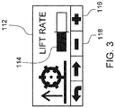
- the display may include a symbol such as a bar graph 114 showing the lift rate setting.
- the display input may be manual controls such as plus/minus buttons 116, 118 that an operator may use to adjust the lift rate to suit mowing conditions.
- the manual controls may adjust the current to the proportional solenoid valve which changes the bypass rate for the hydraulic cylinders of the lift and lower system.
- adjustable lift rate system 100 may include a ramped current profile to the proportional solenoid valve.
- the ramped current profile may be used to lift or lower the cutting units while mowing.
- the current to the proportional solenoid may be held constant if the cutting units are lifted and lowered while in transport.
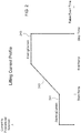
- Fig. 3 shows the raise event time on the horizontal axis.
- Current to the proportional solenoid valve is on the vertical axis.
- the ramped current profile 242 may slow the lift rate as the cutting units approach the top of the lift. This keeps the cutting units from bouncing and softens the impact of the cutting units against upper stops.
- the ramped current profile also may be used to slow the lower rate as the cutting units reach the ground.
- the adjustable lift rate system also may slow control of the front two lift cylinders independently from the one rear lift cylinder.
- the adjustable lift rate system may include a vehicle controller with software logic shown in Fig 4 , starting in block 200. If the adjustable lift rate system is not enabled in block 201, the current to the proportional solenoid valve may be set as a non-adjusted value in block 202. If the adjustable lift rate system is enabled, a look up table in block 203 may be used to determine the starting maximum current, starting minimum current, ending maximum current and ending minimum current for the proportional solenoid valve. The look up table may use engine speed to determine initial minimums and maximums, and to determine value ranges for the starting and ending currents. For example, the starting and ending values of the ramp may be determined using engine speed breakpoints.
- the adjustable lift rate system then may calculate the starting current, ending current, start timer and end timer in block 204, based on the operator input to the display, along with the minimum and maximum starting and ending currents found in block 203.
- the system may determine if the hold to raise flag is on, indicating the PTO switch is off for transport. If it is in transport, a look up table in block 207 may be used to determine the minimum and maximum current to the proportional solenoid.
- the current to the proportional solenoid then may be set as a constant in block 208 based on the operator input described above, and the transport minimum and maximum current.
- current to the proportional solenoid may be set at a constant starting current for the duration of the start timer, current may be ramped up until the end timer, and then held constant at an ending current until the raise timer finishes.
- the adjustable lift rate system may also be used by an operator to adjust the rate of lowering the cutting units.
- the operator may make the adjustments using the same input on the display.
- the input may be used to adjust the current to the proportional solenoid that bypasses or diverts hydraulic fluid from the hydraulic lift cylinders when lowering the cutting units.
- the adjustable lift rate system may include proportional solenoid valve 128 which may be operator adjustable to divert or reduce the flow rate to lift cylinders 120, 122, 124.
- the hydraulic lift and lower circuit 109 may include left and right front lift cylinders 120, 122 for the left and right front cutting units, and rear lift cylinder 124 for the rear cutting unit.
- the lift and lower circuit also may include lift valve 126 which may be closed when the cutting units are lifted, timing valve 130 to provide a time delay so that the front cutting units may be lifted or lowered before the rear cutting unit, and filtration circuit 132.
Landscapes
- Life Sciences & Earth Sciences (AREA)
- Environmental Sciences (AREA)
- Lifting Devices For Agricultural Implements (AREA)
- Harvester Elements (AREA)
Abstract
Description
- This invention relates generally to grass mowing machines, and specifically to an adjustable lift rate system for cutting units on a riding greensmower, trim and surround mower or fairway mower.
- Grass mowing machines such as riding greensmowers, trim and surround mowers and fairway mowers may include internal combustion engines to power a hydrostatic traction drive circuit, hydraulic mowing circuit, and hydraulic circuits to raise and lower the cutting units, or for other functions.
- In the past, these mowers have included lift and lower systems for the cutting units, with lift arms actuated by hydraulic cylinders. The front row of cutting units may be lifted and lowered before one or more rear cutting units. Variation in the weight of cutting units, and different engine speeds, may affect the lift rate for cutting units which may be undesirable for the mowing conditions. An adjustable lift rate system is needed that an operator may use to adjust lift rates to be suitable for different mowing conditions, cutting units, and engine speeds. An adjustable lift rate system also is needed that can slow the drop rate as the cutting units approach the ground.
- An adjustable lift rate system for raising and lowering a plurality of cutting units of a grass mowing machine. The rate of raising and lowering the cutting units may be operator adjustable using a display. The adjustment may change the current to a proportional solenoid valve to bypass the hydraulic cylinders for the lift arms.
-
-
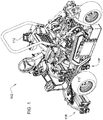
Fig. 1 is a perspective view of a riding greensmower with an adjustable lift rate system according to one embodiment of the invention. -
Fig. 2 is a diagram of a current profile of an adjustable lift rate system according to one embodiment of the invention. -
Fig. 3 is a drawing of an operator input device of an adjustable lift rate system according to one embodiment of the invention. -
Fig. 4 is a logic diagram for computer software that may be used in the adjustable lift rate system according to one embodiment of the invention. -
Fig. 5 is a hydraulic schematic drawing of a raise/lower subcircuit with an adjustable lift rate system according to one embodiment of the invention. - In an embodiment shown in
Figs. 1-5 , adjustable lift rate system 100 may be onriding greensmower 102 having three or more reel cutting units, or on a trim and surround mower or fairway mower with multiple reel cutting units. The mower may be powered by internal combustion engine 104, and may have a hydrostatictraction drive circuit 106, and/orhydraulic mow circuit 108, and lift andlower circuit 109 for the cutting units. - In one embodiment, the adjustable lift rate system may include a
proportional solenoid valve 128 to divert hydraulic fluid to bypasshydraulic cylinders - In one embodiment shown in
Figs. 1-5 , the adjustable lift rate system may include adisplay 112 on the mower that an operator may use to adjust the lift rate. The display may include a symbol such as abar graph 114 showing the lift rate setting. The display input may be manual controls such as plus/minus buttons - In an embodiment, shown in
Fig. 3 , adjustable lift rate system 100 may include a ramped current profile to the proportional solenoid valve. The ramped current profile may be used to lift or lower the cutting units while mowing. The current to the proportional solenoid may be held constant if the cutting units are lifted and lowered while in transport.Fig. 3 shows the raise event time on the horizontal axis. Current to the proportional solenoid valve is on the vertical axis. When the operator actuates a switch to lift the cutting units, thestarting current 241 may be constant until a start timer expires. Then the current may ramp up as shown at 242. When the end timer expires, ending current 243 may be held constant until the raise timer ends. The rampedcurrent profile 242 may slow the lift rate as the cutting units approach the top of the lift. This keeps the cutting units from bouncing and softens the impact of the cutting units against upper stops. The ramped current profile also may be used to slow the lower rate as the cutting units reach the ground. The adjustable lift rate system also may slow control of the front two lift cylinders independently from the one rear lift cylinder. - In one embodiment, the adjustable lift rate system may include a vehicle controller with software logic shown in
Fig 4 , starting inblock 200. If the adjustable lift rate system is not enabled inblock 201, the current to the proportional solenoid valve may be set as a non-adjusted value inblock 202. If the adjustable lift rate system is enabled, a look up table inblock 203 may be used to determine the starting maximum current, starting minimum current, ending maximum current and ending minimum current for the proportional solenoid valve. The look up table may use engine speed to determine initial minimums and maximums, and to determine value ranges for the starting and ending currents. For example, the starting and ending values of the ramp may be determined using engine speed breakpoints. The adjustable lift rate system then may calculate the starting current, ending current, start timer and end timer inblock 204, based on the operator input to the display, along with the minimum and maximum starting and ending currents found inblock 203. Inblock 205, the system may determine if the hold to raise flag is on, indicating the PTO switch is off for transport. If it is in transport, a look up table inblock 207 may be used to determine the minimum and maximum current to the proportional solenoid. The current to the proportional solenoid then may be set as a constant inblock 208 based on the operator input described above, and the transport minimum and maximum current. Inblock 206, if the hold to raise flag is off, indicating the PTO is on for mowing, current to the proportional solenoid may be set at a constant starting current for the duration of the start timer, current may be ramped up until the end timer, and then held constant at an ending current until the raise timer finishes. - In one embodiment, the adjustable lift rate system may also be used by an operator to adjust the rate of lowering the cutting units. The operator may make the adjustments using the same input on the display. The input may be used to adjust the current to the proportional solenoid that bypasses or diverts hydraulic fluid from the hydraulic lift cylinders when lowering the cutting units.
- As shown in the hydraulic schematic diagram of
Fig. 5 , the adjustable lift rate system may includeproportional solenoid valve 128 which may be operator adjustable to divert or reduce the flow rate to liftcylinders lower circuit 109 may include left and rightfront lift cylinders rear lift cylinder 124 for the rear cutting unit. The lift and lower circuit also may includelift valve 126 which may be closed when the cutting units are lifted,timing valve 130 to provide a time delay so that the front cutting units may be lifted or lowered before the rear cutting unit, andfiltration circuit 132. If the operator uses the display to slow the lift rate, current to the proportional solenoid valve increases, and the proportional solenoid valve diverts more hydraulic fluid from the lift cylinders. If the operator uses the display to speed up the lift rate, current to the proportional solenoid valve decreases, and the proportional solenoid diverts less hydraulic fluid from the lift cylinders. - Having described a preferred embodiment, it will become apparent that various modifications can be made without departing from the scope of the invention as defined in the accompanying claims.
Claims (12)
- An adjustable lift rate system, comprising:a riding greensmower having a lift and lower circuit including a plurality of hydraulic lift cylinders to lift and lower a plurality of cutting units; anda controller providing a current to a proportional solenoid valve to bypass the hydraulic lift cylinders; andan operator control on the riding greensmower for adjusting the current to the proportional solenoid valve to adjust a lift rate and a lower rate of the plurality of cutting units.
- The adjustable lift rate system of claim 1 wherein the current to the proportional solenoid valve increases during the lifting of the plurality of cutting units.
- The adjustable lift rate system of claim 1 wherein the current to the proportional solenoid valve increases to slow the lift rate of the plurality of cutting units.
- The adjustable lift rate system of claim 1 wherein the controller provides a constant starting current, a ramp of increasing current, and a constant ending current to the proportional solenoid valve.
- An adjustable lift rate system comprising:a lift and lower circuit for raising and lowering a plurality of cutting units of a grass mowing machine; anda controller that controls a rate of raising and lowering the cutting units based on an operator adjustable display, and reduces the rate during the raising and lowering of the plurality of cutting units.
- The adjustable lift rate system of claim 5 wherein the lift and lower circuit is a hydraulic circuit having a plurality of hydraulic cylinders.
- The adjustable lift rate system of claim 5 further comprising a proportional solenoid valve that receives an increased current from the controller to reduce the rate during raising of the plurality of cutting units.
- The adjustable lift rate system of claim 7 wherein the increased current from the controller includes a starting current that is constant, a ramp of increased current, and an ending current that is constant from the controller.
- An adjustable lift rate system comprising:a plurality of cutting units, each cutting unit supported by a lift arm that is raised and lowered using a hydraulic cylinder; anda proportional solenoid valve that is operator adjustable to adjust how much hydraulic fluid is diverted from the hydraulic cylinders.
- The adjustable lift rate system of claim 9 wherein a current to the proportional solenoid valve is operator adjustable and increases as the hydraulic fluid diverted from the hydraulic cylinders increases.
- The adjustable lift rate system of claim 10 wherein the current increases as the cutting units are raised or lowered.
- The adjustable lift rate system of claim 11, wherein the starting current is constant, then the current ramps up, and the ending current is constant.
Applications Claiming Priority (1)
| Application Number | Priority Date | Filing Date | Title |
|---|---|---|---|
| US16/802,008 US12063891B2 (en) | 2020-02-26 | 2020-02-26 | Adjustable lift rate system for grass mowing machine |
Publications (2)
| Publication Number | Publication Date |
|---|---|
| EP3871483A1 true EP3871483A1 (en) | 2021-09-01 |
| EP3871483B1 EP3871483B1 (en) | 2025-07-16 |
Family
ID=74418264
Family Applications (1)
| Application Number | Title | Priority Date | Filing Date |
|---|---|---|---|
| EP21154289.9A Active EP3871483B1 (en) | 2020-02-26 | 2021-01-29 | Adjustable lift rate system for mower cutting units |
Country Status (2)
| Country | Link |
|---|---|
| US (1) | US12063891B2 (en) |
| EP (1) | EP3871483B1 (en) |
Families Citing this family (2)
| Publication number | Priority date | Publication date | Assignee | Title |
|---|---|---|---|---|
| WO2020053670A1 (en) * | 2018-09-14 | 2020-03-19 | Husqvarna Ab | Multi-position locking mechanism for a riding lawn care vehicle |
| US12471513B2 (en) | 2022-09-07 | 2025-11-18 | Textron Innovations Inc. | Turf mower hydraulic lift control system and method |
Citations (3)
| Publication number | Priority date | Publication date | Assignee | Title |
|---|---|---|---|---|
| WO1994024844A1 (en) * | 1993-02-01 | 1994-11-10 | Control Concepts, Inc. | Agricultural harvester with closed loop header control |
| EP1958496A1 (en) * | 2007-02-16 | 2008-08-20 | Deere & Company | Shift mechanism for trim mower cutting units |
| US20170188509A1 (en) * | 2016-01-06 | 2017-07-06 | Deere & Company | Grass mowing machine with hydraulic circuit having diverter valve |
Family Cites Families (12)
| Publication number | Priority date | Publication date | Assignee | Title |
|---|---|---|---|---|
| GB8611932D0 (en) | 1986-05-16 | 1986-06-25 | Ransomes Sims & Jefferies Plc | Grass cutting machine |
| US4864805A (en) * | 1987-09-04 | 1989-09-12 | The Toro Company | System for supporting a working unit |
| US5123234A (en) | 1990-10-02 | 1992-06-23 | Kubota Corporation | Working vehicle having a mower unit vertically movable relative to a vehicle body |
| US5524424A (en) * | 1994-12-13 | 1996-06-11 | Case Corporation | Electronic area counter for a combine |
| US5822960A (en) * | 1996-07-09 | 1998-10-20 | Kubota Corporation | Reel mower |
| US6052973A (en) * | 1997-01-21 | 2000-04-25 | Kubota Corporation | Lift mechanism for reel-type cutting units |
| US5934051A (en) | 1997-02-06 | 1999-08-10 | Textron, Inc. | Solid state mow system for electrically powered mower |
| JP3359837B2 (en) | 1997-04-03 | 2002-12-24 | 株式会社クボタ | Mower lifting and lowering device for lawn mower |
| US6032441A (en) | 1997-11-13 | 2000-03-07 | The Toro Company | Triplex trim mower with laterally adjustable cutting units |
| JP2004100759A (en) * | 2002-09-06 | 2004-04-02 | Komatsu Ltd | Swing control device for swing type excavator |
| US7104054B1 (en) * | 2005-04-05 | 2006-09-12 | Cnh America Llc | Hydraulic cylinder cushioning |
| US11089727B2 (en) * | 2018-02-23 | 2021-08-17 | Macdon Industries | Harvesting machine with programmable inputs for header height and auxiliary function control |
-
2020
- 2020-02-26 US US16/802,008 patent/US12063891B2/en active Active
-
2021
- 2021-01-29 EP EP21154289.9A patent/EP3871483B1/en active Active
Patent Citations (3)
| Publication number | Priority date | Publication date | Assignee | Title |
|---|---|---|---|---|
| WO1994024844A1 (en) * | 1993-02-01 | 1994-11-10 | Control Concepts, Inc. | Agricultural harvester with closed loop header control |
| EP1958496A1 (en) * | 2007-02-16 | 2008-08-20 | Deere & Company | Shift mechanism for trim mower cutting units |
| US20170188509A1 (en) * | 2016-01-06 | 2017-07-06 | Deere & Company | Grass mowing machine with hydraulic circuit having diverter valve |
Also Published As
| Publication number | Publication date |
|---|---|
| US20210259154A1 (en) | 2021-08-26 |
| EP3871483B1 (en) | 2025-07-16 |
| US12063891B2 (en) | 2024-08-20 |
Similar Documents
| Publication | Publication Date | Title |
|---|---|---|
| EP2801248B1 (en) | End of cut speed control system | |
| EP3871483B1 (en) | Adjustable lift rate system for mower cutting units | |
| US9699961B2 (en) | Mowing vehicle including arrangement for raising/lowering height of a mower unit | |
| US9781880B2 (en) | Control of base cutter height for multiple row sugar cane harvesters | |
| BE1023154B1 (en) | Double mower assembly | |
| CN114223386A (en) | A kind of control method of combine harvester reel operating parameter control system | |
| US7707810B2 (en) | Apparatus and method to vary the reel speed versus ground speed of an agricultural windrower | |
| EP3837953B1 (en) | Agricultural apparatus | |
| JP3670056B2 (en) | Combine | |
| JPH0810253Y2 (en) | Combine harvester | |
| JP2003189716A (en) | Lifting control mechanism for working unit | |
| JP3057699B2 (en) | Combine cutting height control device | |
| JPH03117425A (en) | combine | |
| JP2593859B2 (en) | Combine swivel | |
| JP2569699B2 (en) | Tractor lifting control | |
| JP2517889B2 (en) | Automatic cutting height control method for combine harvesters | |
| JP4095224B2 (en) | Posture control device for auxiliary cutting blade device in combine | |
| TH2101002801A (en) | Agricultural vehicles, Agricultural vehicle control programs, Recording media on which the agricultural vehicle control program is recorded, Methods for controlling agricultural vehicles, Harvesters, Harvester control programs, Recording media on which the harvester control program is recorded and Methods for controlling the harvester | |
| JPH0595715A (en) | Lift control unit for reaping component in reaping harvester | |
| JPH06319337A (en) | Reaping height controller for reaping harvester | |
| JP3108678B2 (en) | Combine | |
| JP2965482B2 (en) | Grain stalk feeder in combine | |
| JPH07274650A (en) | Lifting control device for pre-mowing treatment device in combine harvester | |
| JPH10229732A (en) | Combine | |
| JP2001061331A (en) | Combine |
Legal Events
| Date | Code | Title | Description |
|---|---|---|---|
| PUAI | Public reference made under article 153(3) epc to a published international application that has entered the european phase |
Free format text: ORIGINAL CODE: 0009012 |
|
| STAA | Information on the status of an ep patent application or granted ep patent |
Free format text: STATUS: THE APPLICATION HAS BEEN PUBLISHED |
|
| AK | Designated contracting states |
Kind code of ref document: A1 Designated state(s): AL AT BE BG CH CY CZ DE DK EE ES FI FR GB GR HR HU IE IS IT LI LT LU LV MC MK MT NL NO PL PT RO RS SE SI SK SM TR |
|
| STAA | Information on the status of an ep patent application or granted ep patent |
Free format text: STATUS: REQUEST FOR EXAMINATION WAS MADE |
|
| 17P | Request for examination filed |
Effective date: 20220301 |
|
| RBV | Designated contracting states (corrected) |
Designated state(s): AL AT BE BG CH CY CZ DE DK EE ES FI FR GB GR HR HU IE IS IT LI LT LU LV MC MK MT NL NO PL PT RO RS SE SI SK SM TR |
|
| GRAP | Despatch of communication of intention to grant a patent |
Free format text: ORIGINAL CODE: EPIDOSNIGR1 |
|
| STAA | Information on the status of an ep patent application or granted ep patent |
Free format text: STATUS: GRANT OF PATENT IS INTENDED |
|
| RIC1 | Information provided on ipc code assigned before grant |
Ipc: A01D 34/74 20060101ALN20250206BHEP Ipc: A01D 34/54 20060101ALI20250206BHEP Ipc: A01D 34/00 20060101AFI20250206BHEP |
|
| INTG | Intention to grant announced |
Effective date: 20250305 |
|
| GRAS | Grant fee paid |
Free format text: ORIGINAL CODE: EPIDOSNIGR3 |
|
| GRAA | (expected) grant |
Free format text: ORIGINAL CODE: 0009210 |
|
| STAA | Information on the status of an ep patent application or granted ep patent |
Free format text: STATUS: THE PATENT HAS BEEN GRANTED |
|
| AK | Designated contracting states |
Kind code of ref document: B1 Designated state(s): AL AT BE BG CH CY CZ DE DK EE ES FI FR GB GR HR HU IE IS IT LI LT LU LV MC MK MT NL NO PL PT RO RS SE SI SK SM TR |
|
| REG | Reference to a national code |
Ref country code: GB Ref legal event code: FG4D |
|
| REG | Reference to a national code |
Ref country code: CH Ref legal event code: EP |
|
| REG | Reference to a national code |
Ref country code: DE Ref legal event code: R096 Ref document number: 602021034037 Country of ref document: DE |
|
| REG | Reference to a national code |
Ref country code: IE Ref legal event code: FG4D |
|
| REG | Reference to a national code |
Ref country code: CH Ref legal event code: W10 Free format text: ST27 STATUS EVENT CODE: U-0-0-W10-W00 (AS PROVIDED BY THE NATIONAL OFFICE) Effective date: 20251119 Ref country code: NL Ref legal event code: MP Effective date: 20250716 |
|
| PG25 | Lapsed in a contracting state [announced via postgrant information from national office to epo] |
Ref country code: PT Free format text: LAPSE BECAUSE OF FAILURE TO SUBMIT A TRANSLATION OF THE DESCRIPTION OR TO PAY THE FEE WITHIN THE PRESCRIBED TIME-LIMIT Effective date: 20251117 |
|
| PG25 | Lapsed in a contracting state [announced via postgrant information from national office to epo] |
Ref country code: NL Free format text: LAPSE BECAUSE OF FAILURE TO SUBMIT A TRANSLATION OF THE DESCRIPTION OR TO PAY THE FEE WITHIN THE PRESCRIBED TIME-LIMIT Effective date: 20250716 |
|
| REG | Reference to a national code |
Ref country code: AT Ref legal event code: MK05 Ref document number: 1813145 Country of ref document: AT Kind code of ref document: T Effective date: 20250716 |
|
| RAP4 | Party data changed (patent owner data changed or rights of a patent transferred) |
Owner name: DEERE & COMPANY |
|
| PG25 | Lapsed in a contracting state [announced via postgrant information from national office to epo] |
Ref country code: IS Free format text: LAPSE BECAUSE OF FAILURE TO SUBMIT A TRANSLATION OF THE DESCRIPTION OR TO PAY THE FEE WITHIN THE PRESCRIBED TIME-LIMIT Effective date: 20251116 |
|
| PG25 | Lapsed in a contracting state [announced via postgrant information from national office to epo] |
Ref country code: NO Free format text: LAPSE BECAUSE OF FAILURE TO SUBMIT A TRANSLATION OF THE DESCRIPTION OR TO PAY THE FEE WITHIN THE PRESCRIBED TIME-LIMIT Effective date: 20251016 |
|
| REG | Reference to a national code |
Ref country code: LT Ref legal event code: MG9D |
|
| PG25 | Lapsed in a contracting state [announced via postgrant information from national office to epo] |
Ref country code: AT Free format text: LAPSE BECAUSE OF FAILURE TO SUBMIT A TRANSLATION OF THE DESCRIPTION OR TO PAY THE FEE WITHIN THE PRESCRIBED TIME-LIMIT Effective date: 20250716 |
|
| PG25 | Lapsed in a contracting state [announced via postgrant information from national office to epo] |
Ref country code: FI Free format text: LAPSE BECAUSE OF FAILURE TO SUBMIT A TRANSLATION OF THE DESCRIPTION OR TO PAY THE FEE WITHIN THE PRESCRIBED TIME-LIMIT Effective date: 20250716 |
|
| PG25 | Lapsed in a contracting state [announced via postgrant information from national office to epo] |
Ref country code: HR Free format text: LAPSE BECAUSE OF FAILURE TO SUBMIT A TRANSLATION OF THE DESCRIPTION OR TO PAY THE FEE WITHIN THE PRESCRIBED TIME-LIMIT Effective date: 20250716 |
|
| PG25 | Lapsed in a contracting state [announced via postgrant information from national office to epo] |
Ref country code: GR Free format text: LAPSE BECAUSE OF FAILURE TO SUBMIT A TRANSLATION OF THE DESCRIPTION OR TO PAY THE FEE WITHIN THE PRESCRIBED TIME-LIMIT Effective date: 20251017 |
|
| PG25 | Lapsed in a contracting state [announced via postgrant information from national office to epo] |
Ref country code: SE Free format text: LAPSE BECAUSE OF FAILURE TO SUBMIT A TRANSLATION OF THE DESCRIPTION OR TO PAY THE FEE WITHIN THE PRESCRIBED TIME-LIMIT Effective date: 20250716 |
|
| PG25 | Lapsed in a contracting state [announced via postgrant information from national office to epo] |
Ref country code: LV Free format text: LAPSE BECAUSE OF FAILURE TO SUBMIT A TRANSLATION OF THE DESCRIPTION OR TO PAY THE FEE WITHIN THE PRESCRIBED TIME-LIMIT Effective date: 20250716 |
|
| PG25 | Lapsed in a contracting state [announced via postgrant information from national office to epo] |
Ref country code: BG Free format text: LAPSE BECAUSE OF FAILURE TO SUBMIT A TRANSLATION OF THE DESCRIPTION OR TO PAY THE FEE WITHIN THE PRESCRIBED TIME-LIMIT Effective date: 20250716 Ref country code: PL Free format text: LAPSE BECAUSE OF FAILURE TO SUBMIT A TRANSLATION OF THE DESCRIPTION OR TO PAY THE FEE WITHIN THE PRESCRIBED TIME-LIMIT Effective date: 20250716 |
|
| PG25 | Lapsed in a contracting state [announced via postgrant information from national office to epo] |
Ref country code: RS Free format text: LAPSE BECAUSE OF FAILURE TO SUBMIT A TRANSLATION OF THE DESCRIPTION OR TO PAY THE FEE WITHIN THE PRESCRIBED TIME-LIMIT Effective date: 20251016 |
|
| PG25 | Lapsed in a contracting state [announced via postgrant information from national office to epo] |
Ref country code: ES Free format text: LAPSE BECAUSE OF FAILURE TO SUBMIT A TRANSLATION OF THE DESCRIPTION OR TO PAY THE FEE WITHIN THE PRESCRIBED TIME-LIMIT Effective date: 20250716 |
|
| PG25 | Lapsed in a contracting state [announced via postgrant information from national office to epo] |
Ref country code: SM Free format text: LAPSE BECAUSE OF FAILURE TO SUBMIT A TRANSLATION OF THE DESCRIPTION OR TO PAY THE FEE WITHIN THE PRESCRIBED TIME-LIMIT Effective date: 20250716 |
|
| PGFP | Annual fee paid to national office [announced via postgrant information from national office to epo] |
Ref country code: GB Payment date: 20260127 Year of fee payment: 6 |
|
| PG25 | Lapsed in a contracting state [announced via postgrant information from national office to epo] |
Ref country code: DK Free format text: LAPSE BECAUSE OF FAILURE TO SUBMIT A TRANSLATION OF THE DESCRIPTION OR TO PAY THE FEE WITHIN THE PRESCRIBED TIME-LIMIT Effective date: 20250716 |
|
| PGFP | Annual fee paid to national office [announced via postgrant information from national office to epo] |
Ref country code: DE Payment date: 20251219 Year of fee payment: 6 |
|
| PG25 | Lapsed in a contracting state [announced via postgrant information from national office to epo] |
Ref country code: IT Free format text: LAPSE BECAUSE OF FAILURE TO SUBMIT A TRANSLATION OF THE DESCRIPTION OR TO PAY THE FEE WITHIN THE PRESCRIBED TIME-LIMIT Effective date: 20250716 |
|
| PG25 | Lapsed in a contracting state [announced via postgrant information from national office to epo] |
Ref country code: CZ Free format text: LAPSE BECAUSE OF FAILURE TO SUBMIT A TRANSLATION OF THE DESCRIPTION OR TO PAY THE FEE WITHIN THE PRESCRIBED TIME-LIMIT Effective date: 20250716 |
|
| PG25 | Lapsed in a contracting state [announced via postgrant information from national office to epo] |
Ref country code: SK Free format text: LAPSE BECAUSE OF FAILURE TO SUBMIT A TRANSLATION OF THE DESCRIPTION OR TO PAY THE FEE WITHIN THE PRESCRIBED TIME-LIMIT Effective date: 20250716 Ref country code: EE Free format text: LAPSE BECAUSE OF FAILURE TO SUBMIT A TRANSLATION OF THE DESCRIPTION OR TO PAY THE FEE WITHIN THE PRESCRIBED TIME-LIMIT Effective date: 20250716 |