EP3871481A1 - Agricultural vehicle provided with a front and a rear 3 d imaging device - Google Patents
Agricultural vehicle provided with a front and a rear 3 d imaging device Download PDFInfo
- Publication number
- EP3871481A1 EP3871481A1 EP21159821.4A EP21159821A EP3871481A1 EP 3871481 A1 EP3871481 A1 EP 3871481A1 EP 21159821 A EP21159821 A EP 21159821A EP 3871481 A1 EP3871481 A1 EP 3871481A1
- Authority
- EP
- European Patent Office
- Prior art keywords
- vehicle
- field
- designed
- agricultural vehicle
- fah
- Prior art date
- Legal status (The legal status is an assumption and is not a legal conclusion. Google has not performed a legal analysis and makes no representation as to the accuracy of the status listed.)
- Granted
Links
Images


Classifications
-
- A—HUMAN NECESSITIES
- A01—AGRICULTURE; FORESTRY; ANIMAL HUSBANDRY; HUNTING; TRAPPING; FISHING
- A01B—SOIL WORKING IN AGRICULTURE OR FORESTRY; PARTS, DETAILS, OR ACCESSORIES OF AGRICULTURAL MACHINES OR IMPLEMENTS, IN GENERAL
- A01B69/00—Steering of agricultural machines or implements; Guiding agricultural machines or implements on a desired track
- A01B69/001—Steering by means of optical assistance, e.g. television cameras
-
- A—HUMAN NECESSITIES
- A01—AGRICULTURE; FORESTRY; ANIMAL HUSBANDRY; HUNTING; TRAPPING; FISHING
- A01B—SOIL WORKING IN AGRICULTURE OR FORESTRY; PARTS, DETAILS, OR ACCESSORIES OF AGRICULTURAL MACHINES OR IMPLEMENTS, IN GENERAL
- A01B63/00—Lifting or adjusting devices or arrangements for agricultural machines or implements
-
- A—HUMAN NECESSITIES
- A01—AGRICULTURE; FORESTRY; ANIMAL HUSBANDRY; HUNTING; TRAPPING; FISHING
- A01D—HARVESTING; MOWING
- A01D41/00—Combines, i.e. harvesters or mowers combined with threshing devices
- A01D41/12—Details of combines
- A01D41/127—Control or measuring arrangements specially adapted for combines
- A01D41/1278—Control or measuring arrangements specially adapted for combines for automatic steering
-
- A—HUMAN NECESSITIES
- A01—AGRICULTURE; FORESTRY; ANIMAL HUSBANDRY; HUNTING; TRAPPING; FISHING
- A01B—SOIL WORKING IN AGRICULTURE OR FORESTRY; PARTS, DETAILS, OR ACCESSORIES OF AGRICULTURAL MACHINES OR IMPLEMENTS, IN GENERAL
- A01B69/00—Steering of agricultural machines or implements; Guiding agricultural machines or implements on a desired track
- A01B69/007—Steering or guiding of agricultural vehicles, e.g. steering of the tractor to keep the plough in the furrow
- A01B69/008—Steering or guiding of agricultural vehicles, e.g. steering of the tractor to keep the plough in the furrow automatic
-
- A—HUMAN NECESSITIES
- A01—AGRICULTURE; FORESTRY; ANIMAL HUSBANDRY; HUNTING; TRAPPING; FISHING
- A01B—SOIL WORKING IN AGRICULTURE OR FORESTRY; PARTS, DETAILS, OR ACCESSORIES OF AGRICULTURAL MACHINES OR IMPLEMENTS, IN GENERAL
- A01B79/00—Methods for working soil
- A01B79/005—Precision agriculture
Definitions
- the present invention relates to an agricultural vehicle provided with a front and a rear 3D imaging device.
- Autonomous guidance systems are normally based on the use of digital signal processing to elaborate information provided by sensors configured to detect the surroundings of the agricultural vehicle for taking autonomous decisions on how to control the agricultural vehicle.
- the previously described aim is obtained by the present invention that relates to an agricultural vehicle provided with a front and a rear 3D imaging device.
- Numeral 1 indicates, as a whole, an agriculture vehicle 1 wherein a vehicle body 3 is provided with a cab 4 for the operator.
- a tractor 1-t whose mechanical structure is of a known kind.
- the vehicle 1 is provided with a front three dimensional imaging device 5 (LIDAR sensor in the preferred example) configured to scan a field ahead (Fah) that is the ground area in front of the vehicle 1 towards which the vehicle is moving (see the arrow showing the direction of the vehicle 1) and a rear three dimensional imaging device 6 (LIDAR sensor in the preferred example) configured to scan a field behind (Fbh) that is a rear area on which the vehicle has previously moved.
- a front three dimensional imaging device 5 LIDAR sensor in the preferred example
- Fah field ahead
- Fbh field behind
- the front LIDAR sensor 5 is carried by a front portion of the vehicle (the hood 7 in the example) and the rear LIDAR 6 is carried by a rear portion of the vehicle: both sensors 5,6 have optical axes L1, L2 inclined with respect to the horizontal direction.
- a LIDAR system fires rapid pulses of laser light at a surface, and then it measures the amount of time it takes for each pulse to bounce back after being reflected by objects in the surroundings. Differences in laser return times and intensities can then be used to make digital 3-D representations of the environment by means of point clouds.
- Imaging devices 5 and 6 may be of different kind such as 3D Stereo-Camera, a 3D RADAR, or a 3D Ultrasound sensor, etc.
- Vehicle 1 is provided with a GPS system 8 (of known kind) configured to provide position and coordinates of the scanned field ahead Fah and of the scanned field behind Fbh.
- a GPS system 8 (of known kind) configured to provide position and coordinates of the scanned field ahead Fah and of the scanned field behind Fbh.
- Each point cloud or group of points acquired by one of the two LIDARs 5, 6 are GPS-tagged.
- the vehicle 1 is also provided with an electronic unit 10, on which runs a software capable of comparing point clouds of the field ahead Fah and of field behind Fbh to provide autonomous guidance to the agricultural vehicle 1 and/or to automate the agricultural operations performed by the agricultural vehicle 1.
- the software implements Artificial Intelligence algorithms.
- Each GEO-tagged point cloud that is collected by the LIDARs is made available to other vehicles operating in the same area, for instance by means of wireless technology of known kind 18 (see, for instance, the example of figure 2 ), to enable automatic subsequent operations of agricultural machines (examples are described below).
- the agricultural vehicle 1 is a tractor provided with a hay rake (or a windrower) 15 (of known kind) designed to collect cut hay or forage into at least a windrow 17 for later harvesting; as it is known a windrow 17 is a row of cut or mown hay or small grain crop.
- a hay rake or a windrower 15 (of known kind) designed to collect cut hay or forage into at least a windrow 17 for later harvesting; as it is known a windrow 17 is a row of cut or mown hay or small grain crop.
- the rear LIDAR 6 scans the field behind Fbh and collects GEO-tagged point clouds that represent a map comprising the windrow 17.
- the electronic unit 10 is designed to detect the presence and the position of the windrow 17 in map of the field behind Fbh for estimating the shape and the volume of the windrow 17.
- the electronic unit 10 is also designed to share the position/map of the windrow 17 (for instance by means of wireless techniques 18 of known kind) to another baler/harvester vehicle 20, which is following the agricultural vehicle 1-t and is designed for collecting the windrow 17.
- vehicle 20 exploits the map that was previously updated by former vehicle, together with its front LIDAR to scan the field ahead Fah, in order to harvest the crop.
- the rear LIDAR of vehicle 20 then scans the field behind Fbh and again the electronic unit 10 updates the map of the field behind Fbh where the windrow is no longer present.
- the agricultural vehicle is a harvester 1-h designed to cut and collect crop 22.
- the electronic unit 10 is designed to detect the position and shape of the field crop 22 based on the point cloud of the field ahead Fah to be harvested and is designed to guide the agricultural vehicle accordingly.
- the electronic unit compares such point cloud with the field behind Fbh, acquired with the rear LiDAR 6 after the operation was performed: this allows to estimate the amount of harvested crop and/or the harvesting quality.
- the agricultural vehicle 1-p is a tractor provided with a plough 23.
- the field ahead Fah scanned by the front LIDAR 5 device is exploited for guiding the tractor in the field in order to perform autonomous ploughing.
- the point cloud of the field behind Fbh, collected by the rear LIDAR 6, is processed by the electronic unit 10 and is exploited to map the position of the furrows 25 that the plough 23 has cut in the soil.
- the electronic unit can measure the depth and shape of the furrows 25 that the plough has cut in the soil, by analyzing the acquired point cloud, and the tractor can control the plough implement accordingly with respect to a user-defined target.
- the agricultural vehicle is a tractor 1-b provided with a pruner 29 designed to cut branches of trees in a vineyard or orchard.
- the map of the field ahead Fah scanned by the front LIDAR 5 is exploited for guiding the vehicle through the vineyard or orchard.
- the electronic unit 10 is designed to detect the shape of the trees to be pruned based on the point cloud of the field ahead Fah. Moreover, it is designed to compare such point cloud with that of the field behind Fbh, acquired by the rear LIDAR 6, to evaluate the volume of the pruned branches and to evaluate the quality of the pruning operations.
Landscapes
- Life Sciences & Earth Sciences (AREA)
- Environmental Sciences (AREA)
- Engineering & Computer Science (AREA)
- Mechanical Engineering (AREA)
- Soil Sciences (AREA)
- Control Of Position, Course, Altitude, Or Attitude Of Moving Bodies (AREA)
- Soil Working Implements (AREA)
- Sowing (AREA)
Abstract
Description
- The present invention relates to an agricultural vehicle provided with a front and a rear 3D imaging device.
- The global food demand is rapidly growing as a result of the increasing world population.
- More specifically, in the agricultural field, there is an increasing need of agricultural vehicles configured to operate autonomously with high production rate and improved efficiency. Thus, autonomous guidance is becoming one of the most important fields of innovation for agricultural vehicles, and companies are strongly investing in this field.
- Autonomous guidance systems are normally based on the use of digital signal processing to elaborate information provided by sensors configured to detect the surroundings of the agricultural vehicle for taking autonomous decisions on how to control the agricultural vehicle.
- The scope of the present invention is to enable one or more agricultural vehicles to perform autonomous operations by exploiting a dual three dimensional (3D) imaging device system and a shared field mapping system.
- The previously described aim is obtained by the present invention that relates to an agricultural vehicle provided with a front and a rear 3D imaging device.
- For a better understanding of the present invention, a preferred embodiment is described in the following, by way of a non-limiting example, with reference to the attached drawings wherein:
-
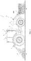
Figure 1 shows schematically an agricultural vehicle provided with a front and a rear 3D imaging device realized according to the present invention; -
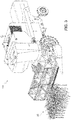
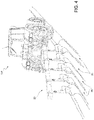
Figures 2 - 5 shown different embodiment of the invention. -
Numeral 1 indicates, as a whole, anagriculture vehicle 1 wherein avehicle body 3 is provided with a cab 4 for the operator. Infigure 1 it is shown a tractor 1-t whose mechanical structure is of a known kind. - According to the present invention the
vehicle 1 is provided with a front three dimensional imaging device 5 (LIDAR sensor in the preferred example) configured to scan a field ahead (Fah) that is the ground area in front of thevehicle 1 towards which the vehicle is moving (see the arrow showing the direction of the vehicle 1) and a rear three dimensional imaging device 6 (LIDAR sensor in the preferred example) configured to scan a field behind (Fbh) that is a rear area on which the vehicle has previously moved. - In the example, the front LIDAR
sensor 5 is carried by a front portion of the vehicle (the hood 7 in the example) and the rear LIDAR 6 is carried by a rear portion of the vehicle: bothsensors -
Imaging devices -
Vehicle 1 is provided with a GPS system 8 (of known kind) configured to provide position and coordinates of the scanned field ahead Fah and of the scanned field behind Fbh. Each point cloud or group of points acquired by one of the twoLIDARs - The
vehicle 1 is also provided with anelectronic unit 10, on which runs a software capable of comparing point clouds of the field ahead Fah and of field behind Fbh to provide autonomous guidance to theagricultural vehicle 1 and/or to automate the agricultural operations performed by theagricultural vehicle 1. Preferably, the software implements Artificial Intelligence algorithms. Each GEO-tagged point cloud that is collected by the LIDARs is made available to other vehicles operating in the same area, for instance by means of wireless technology of known kind 18 (see, for instance, the example offigure 2 ), to enable automatic subsequent operations of agricultural machines (examples are described below). - In the example of
figure 2 , theagricultural vehicle 1 is a tractor provided with a hay rake (or a windrower) 15 (of known kind) designed to collect cut hay or forage into at least awindrow 17 for later harvesting; as it is known awindrow 17 is a row of cut or mown hay or small grain crop. - The rear LIDAR 6 scans the field behind Fbh and collects GEO-tagged point clouds that represent a map comprising the
windrow 17. Theelectronic unit 10 is designed to detect the presence and the position of thewindrow 17 in map of the field behind Fbh for estimating the shape and the volume of thewindrow 17. - Most preferably, the
electronic unit 10 is also designed to share the position/map of the windrow 17 (for instance by means ofwireless techniques 18 of known kind) to another baler/harvester vehicle 20, which is following the agricultural vehicle 1-t and is designed for collecting thewindrow 17.Such vehicle 20 exploits the map that was previously updated by former vehicle, together with its front LIDAR to scan the field ahead Fah, in order to harvest the crop. The rear LIDAR ofvehicle 20 then scans the field behind Fbh and again theelectronic unit 10 updates the map of the field behind Fbh where the windrow is no longer present. - In the example of
figure 3 , the agricultural vehicle is a harvester 1-h designed to cut and collectcrop 22. Theelectronic unit 10 is designed to detect the position and shape of thefield crop 22 based on the point cloud of the field ahead Fah to be harvested and is designed to guide the agricultural vehicle accordingly. In addition, the electronic unit compares such point cloud with the field behind Fbh, acquired with the rear LiDAR 6 after the operation was performed: this allows to estimate the amount of harvested crop and/or the harvesting quality. - In the example of
figure 4 , the agricultural vehicle 1-p is a tractor provided with aplough 23. The field ahead Fah scanned by the front LIDAR 5 device is exploited for guiding the tractor in the field in order to perform autonomous ploughing. The point cloud of the field behind Fbh, collected by the rear LIDAR 6, is processed by theelectronic unit 10 and is exploited to map the position of thefurrows 25 that theplough 23 has cut in the soil. In addition, the electronic unit can measure the depth and shape of thefurrows 25 that the plough has cut in the soil, by analyzing the acquired point cloud, and the tractor can control the plough implement accordingly with respect to a user-defined target. - In the example of
figure 5 , the agricultural vehicle is a tractor 1-b provided with apruner 29 designed to cut branches of trees in a vineyard or orchard. The map of the field ahead Fah scanned by the front LIDAR 5 is exploited for guiding the vehicle through the vineyard or orchard. In addition, theelectronic unit 10 is designed to detect the shape of the trees to be pruned based on the point cloud of the field ahead Fah. Moreover, it is designed to compare such point cloud with that of the field behind Fbh, acquired by the rear LIDAR 6, to evaluate the volume of the pruned branches and to evaluate the quality of the pruning operations.
Claims (10)
- Agricultural vehicle (1) wherein a vehicle body (3) is provided with a cab (4) for the operator:the vehicle (1) is provided with a front three dimensional imaging device (5) configured to scan the field ahead (Fah) that is the area in front of the vehicle (1) towards which the vehicle is moving and a rear three dimensional imaging device (6) configured to scan the field behind (Fbh), that is a rear area on which the vehicle has previously moved;the vehicle (1) is provided with a GPS system (8) configured to provide position and coordinates of the scanned point clouds of the field ahead (Fah) and of the field behind (Fbh);the vehicle is also provided with an electronic unit (10) configured to compare point clouds of the field ahead (Fah) and of field behind (Fbh) to provide autonomous guidance to the agricultural vehicle and/or to automate the agricultural operations performed by the agricultural vehicle.
- Agricultural vehicle as defined in claim 1, wherein said agricultural vehicle is a tractor (1-t) provided with a hay rake (15) designed to collect cut hay or forage into at least a windrow (17) for later harvesting;
the rear imaging device (6) configured to scan the field behind (Fbh) and to collect GEO-tagged point clouds that represent a map comprising the windrow (17);
said electronic unit (10) is designed to detect the shape and position of the windrow (17) in the map for estimating the volume of the windrow (17), based at least on the point cloud of the field behind (Fbh). - System comprising a first agricultural vehicle as defined in claim 2, wherein said electronic unit (10) is designed to transmit the map to another baler/harvester vehicle (20) following in the field said agricultural vehicle (1) and designed for harvesting the windrow (17);
said system further comprising another vehicle (20) that is designed to exploit the map that was previously updated by said first vehicle, together with its front imaging device (5) to scan the field ahead (Fah), in order to harvest the crop. - Agricultural vehicle as defined in claim 1, wherein said agricultural vehicle is a harvester (1-h) designed to cut and collect crop (22);
said electronic unit (10) is designed to detect the position and shape of the field crop (22) based on the point cloud of the field ahead (Fah) to be harvested and is designed to guide the agricultural vehicle accordingly. - Agricultural vehicle as defined in claim 4, wherein said electronic unit is designed to compare the point cloud of the field ahead (Fah) with the point cloud of the field behind (Fbh), acquired with the rear imaging device (6) after the operation was performed in order to estimate the harvested and/or the harvesting quality.
- Agricultural vehicle as defined in claim 1, wherein said agricultural vehicle is a tractor (1-p) provided with a plough (23);
the field ahead (Fah) scanned by the front imaging device (5) is exploited for guiding the tractor in the field in order to perform autonomous ploughing; the point cloud of the field behind (Fbh), collected by the rear LIDAR (6), is processed by the electronic unit (10) and is exploited to map the position of the furrows (25) that the plough (23) has cut in the soil. - Agricultural vehicle as defined in claim 6, wherein the electronic unit (10) is designed to measure the depth and shape of the furrows (25) that the plough has cut in the soil, by analyzing the acquired point cloud, and the tractor is designed to control the plough implement accordingly with respect to a user-defined target.
- Agricultural vehicle as defined in claim 1, wherein said agricultural vehicle is a tractor provided with a pruner (29) designed to cut branches of trees in a vineyard or orchard;
the electronic unit (10) is designed to use the map of the field ahead (Fah) scanned by the front imaging device (5) for guiding the vehicle through the vineyard or orchard. - Agricultural vehicle as defined in claim 8, wherein the electronic unit (10) is designed to detect the shape of the trees to be pruned based on the point cloud of the field ahead (Fah) and it is designed to compare such point cloud with that of the field behind (Fbh), acquired by the rear imaging device (10) to evaluate the volume of the pruned branches and to evaluate the quality of the pruning operations.
- Agricultural vehicle as one of the preceding claim wherein the front/rear imaging device is one of the following:a LIDAR sensor;3D Stereo-Camera,a 3D RADAR, ora 3D Ultrasound sensor.
Applications Claiming Priority (1)
| Application Number | Priority Date | Filing Date | Title |
|---|---|---|---|
| IT102020000004222A IT202000004222A1 (en) | 2020-02-28 | 2020-02-28 | AGRICULTURAL VEHICLE EQUIPPED WITH A FRONT AND A REAR DEVICE FOR THE FORMATION OF THREE-DIMENSIONAL IMAGES |
Publications (2)
| Publication Number | Publication Date |
|---|---|
| EP3871481A1 true EP3871481A1 (en) | 2021-09-01 |
| EP3871481B1 EP3871481B1 (en) | 2024-04-24 |
Family
ID=70480782
Family Applications (1)
| Application Number | Title | Priority Date | Filing Date |
|---|---|---|---|
| EP21159821.4A Active EP3871481B1 (en) | 2020-02-28 | 2021-03-01 | Agricultural vehicle provided with a front and a rear 3 d imaging device |
Country Status (2)
| Country | Link |
|---|---|
| EP (1) | EP3871481B1 (en) |
| IT (1) | IT202000004222A1 (en) |
Cited By (8)
| Publication number | Priority date | Publication date | Assignee | Title |
|---|---|---|---|---|
| US20210246636A1 (en) * | 2020-02-07 | 2021-08-12 | Caterpillar Inc. | System and Method of Autonomously Clearing a Windrow |
| US20230048528A1 (en) * | 2021-08-10 | 2023-02-16 | Claas Tractor Sas | System and method for collecting agricultural measured data in an agricultural production machine |
| FR3127668A1 (en) * | 2021-10-05 | 2023-04-07 | Naïo-Technologies | Autonomous agricultural robot comprising a crop protection device |
| WO2023223320A1 (en) * | 2022-05-16 | 2023-11-23 | Agromentum Ltd. | System and method for agricultural treatment with realtime feedback |
| US20240138284A1 (en) * | 2022-10-31 | 2024-05-02 | Deere & Company | Map based farming for windrower operation |
| EP4552451A1 (en) | 2023-11-08 | 2025-05-14 | CLAAS KGaA mbH | Agricultural machine |
| EP4552452A1 (en) | 2023-11-08 | 2025-05-14 | CLAAS KGaA mbH | Agricultural machine |
| US12527241B2 (en) | 2021-08-10 | 2026-01-20 | Claas Tractor Sas | System and method to measure an absolute working height of a plurality of agricultural attachments |
Citations (4)
| Publication number | Priority date | Publication date | Assignee | Title |
|---|---|---|---|---|
| CN105043247A (en) * | 2014-04-25 | 2015-11-11 | 迪尔公司 | Control system for operation of one or more agricultural operations and method for such |
| DE102016212623A1 (en) * | 2015-07-30 | 2017-02-02 | Deere & Company | UAV-based sensing for workflows in a workspace |
| DE102018200411A1 (en) * | 2018-01-11 | 2019-07-11 | Robert Bosch Gmbh | Method for working a soil and tillage device |
| US20190387658A1 (en) * | 2018-06-21 | 2019-12-26 | Cnh Industrial Canada, Ltd. | Real-time artificial intelligence control of agricultural work vehicle or implement based on observed outcomes |
-
2020
- 2020-02-28 IT IT102020000004222A patent/IT202000004222A1/en unknown
-
2021
- 2021-03-01 EP EP21159821.4A patent/EP3871481B1/en active Active
Patent Citations (4)
| Publication number | Priority date | Publication date | Assignee | Title |
|---|---|---|---|---|
| CN105043247A (en) * | 2014-04-25 | 2015-11-11 | 迪尔公司 | Control system for operation of one or more agricultural operations and method for such |
| DE102016212623A1 (en) * | 2015-07-30 | 2017-02-02 | Deere & Company | UAV-based sensing for workflows in a workspace |
| DE102018200411A1 (en) * | 2018-01-11 | 2019-07-11 | Robert Bosch Gmbh | Method for working a soil and tillage device |
| US20190387658A1 (en) * | 2018-06-21 | 2019-12-26 | Cnh Industrial Canada, Ltd. | Real-time artificial intelligence control of agricultural work vehicle or implement based on observed outcomes |
Cited By (11)
| Publication number | Priority date | Publication date | Assignee | Title |
|---|---|---|---|---|
| US20210246636A1 (en) * | 2020-02-07 | 2021-08-12 | Caterpillar Inc. | System and Method of Autonomously Clearing a Windrow |
| US12024862B2 (en) * | 2020-02-07 | 2024-07-02 | Caterpillar Inc. | System and method of autonomously clearing a windrow |
| US20230048528A1 (en) * | 2021-08-10 | 2023-02-16 | Claas Tractor Sas | System and method for collecting agricultural measured data in an agricultural production machine |
| US12239037B2 (en) * | 2021-08-10 | 2025-03-04 | Claas Tractor Sas | System and method for collecting agricultural measured data in an agricultural production machine |
| US12527241B2 (en) | 2021-08-10 | 2026-01-20 | Claas Tractor Sas | System and method to measure an absolute working height of a plurality of agricultural attachments |
| FR3127668A1 (en) * | 2021-10-05 | 2023-04-07 | Naïo-Technologies | Autonomous agricultural robot comprising a crop protection device |
| WO2023057408A1 (en) * | 2021-10-05 | 2023-04-13 | Naïo-Technologies | Autonomous agricultural robot comprising a crop protection device |
| WO2023223320A1 (en) * | 2022-05-16 | 2023-11-23 | Agromentum Ltd. | System and method for agricultural treatment with realtime feedback |
| US20240138284A1 (en) * | 2022-10-31 | 2024-05-02 | Deere & Company | Map based farming for windrower operation |
| EP4552451A1 (en) | 2023-11-08 | 2025-05-14 | CLAAS KGaA mbH | Agricultural machine |
| EP4552452A1 (en) | 2023-11-08 | 2025-05-14 | CLAAS KGaA mbH | Agricultural machine |
Also Published As
| Publication number | Publication date |
|---|---|
| IT202000004222A1 (en) | 2021-08-28 |
| EP3871481B1 (en) | 2024-04-24 |
Similar Documents
| Publication | Publication Date | Title |
|---|---|---|
| EP3871481B1 (en) | Agricultural vehicle provided with a front and a rear 3 d imaging device | |
| US11937548B2 (en) | System and method for sensing an edge | |
| JP7648650B2 (en) | MOBILE BODY, CONTROL UNIT, AND METHOD FOR CONTROLLING OPERATION OF MOBILE BODY | |
| Rahmadian et al. | Autonomous robotic in agriculture: a review | |
| JP7684327B2 (en) | MOBILE BODY, DATA GENERATION UNIT, AND METHOD FOR GENERATING DATA - Patent application | |
| EP3414982B1 (en) | Method and device for the identification of animals in the machine track of an agricultural field cultivating machine | |
| JP7688045B2 (en) | MOBILE BODY, CONTROL UNIT, DATA GENERATION UNIT, METHOD FOR CONTROLLING OPERATION OF MOBILE BODY, AND METHOD FOR GENERATING DATA | |
| JP7686830B2 (en) | Farm Work Vehicle | |
| EP4562987A2 (en) | Agricultural vehicles including an imaging controller, and related methods | |
| US12181889B2 (en) | Method for controlling a vehicle for harvesting agricultural material | |
| CN110612459A (en) | agricultural system | |
| EP4564306A1 (en) | Agricultural vehicles including an imaging controller, and related methods | |
| US20240099191A1 (en) | Header mounted radar for ground detection and active header control | |
| WO2024004574A1 (en) | Work vehicle, control method and computer program | |
| US20250174029A1 (en) | Agricultural Vehicle with Enhanced Operation and Safety, and Related Methods | |
| JP2022092391A (en) | Mobile vehicle | |
| US20260011110A1 (en) | Evaluation system and evaluation method | |
| US20260000001A1 (en) | Assist system for working machine and method of assisting working machine | |
| JP2025004533A (en) | Crop Detection System | |
| EP4706366A1 (en) | Methods of detecting anomalies associated with agricultural implements, and related agricultural machines | |
| US20260011142A1 (en) | Evaluation system and evaluation method | |
| EP4559299A1 (en) | Implement control for agricultural vehicles | |
| US20260007087A1 (en) | Assist system for working machine and method of assisting working machine | |
| EP4657391A1 (en) | A method and system for identifying plant locations | |
| US20250169389A1 (en) | Agricultural Vehicles Including an Imaging Controller, and Related Methods |
Legal Events
| Date | Code | Title | Description |
|---|---|---|---|
| PUAI | Public reference made under article 153(3) epc to a published international application that has entered the european phase |
Free format text: ORIGINAL CODE: 0009012 |
|
| STAA | Information on the status of an ep patent application or granted ep patent |
Free format text: STATUS: THE APPLICATION HAS BEEN PUBLISHED |
|
| AK | Designated contracting states |
Kind code of ref document: A1 Designated state(s): AL AT BE BG CH CY CZ DE DK EE ES FI FR GB GR HR HU IE IS IT LI LT LU LV MC MK MT NL NO PL PT RO RS SE SI SK SM TR |
|
| STAA | Information on the status of an ep patent application or granted ep patent |
Free format text: STATUS: REQUEST FOR EXAMINATION WAS MADE |
|
| 17P | Request for examination filed |
Effective date: 20220301 |
|
| RBV | Designated contracting states (corrected) |
Designated state(s): AL AT BE BG CH CY CZ DE DK EE ES FI FR GB GR HR HU IE IS IT LI LT LU LV MC MK MT NL NO PL PT RO RS SE SI SK SM TR |
|
| RAP3 | Party data changed (applicant data changed or rights of an application transferred) |
Owner name: CNH INDUSTRIAL ITALIA S.P.A. |
|
| RIC1 | Information provided on ipc code assigned before grant |
Ipc: A01B 79/00 20060101ALN20230711BHEP Ipc: A01B 69/04 20060101ALN20230711BHEP Ipc: A01D 41/127 20060101ALN20230711BHEP Ipc: A01B 63/00 20060101ALI20230711BHEP Ipc: A01B 69/00 20060101AFI20230711BHEP |
|
| GRAP | Despatch of communication of intention to grant a patent |
Free format text: ORIGINAL CODE: EPIDOSNIGR1 |
|
| STAA | Information on the status of an ep patent application or granted ep patent |
Free format text: STATUS: GRANT OF PATENT IS INTENDED |
|
| INTG | Intention to grant announced |
Effective date: 20230823 |
|
| GRAJ | Information related to disapproval of communication of intention to grant by the applicant or resumption of examination proceedings by the epo deleted |
Free format text: ORIGINAL CODE: EPIDOSDIGR1 |
|
| STAA | Information on the status of an ep patent application or granted ep patent |
Free format text: STATUS: REQUEST FOR EXAMINATION WAS MADE |
|
| GRAP | Despatch of communication of intention to grant a patent |
Free format text: ORIGINAL CODE: EPIDOSNIGR1 |
|
| STAA | Information on the status of an ep patent application or granted ep patent |
Free format text: STATUS: GRANT OF PATENT IS INTENDED |
|
| INTC | Intention to grant announced (deleted) | ||
| RIC1 | Information provided on ipc code assigned before grant |
Ipc: A01B 79/00 20060101ALN20231222BHEP Ipc: A01B 69/04 20060101ALN20231222BHEP Ipc: A01D 41/127 20060101ALN20231222BHEP Ipc: A01B 63/00 20060101ALI20231222BHEP Ipc: A01B 69/00 20060101AFI20231222BHEP |
|
| INTG | Intention to grant announced |
Effective date: 20240117 |
|
| GRAS | Grant fee paid |
Free format text: ORIGINAL CODE: EPIDOSNIGR3 |
|
| GRAA | (expected) grant |
Free format text: ORIGINAL CODE: 0009210 |
|
| STAA | Information on the status of an ep patent application or granted ep patent |
Free format text: STATUS: THE PATENT HAS BEEN GRANTED |
|
| AK | Designated contracting states |
Kind code of ref document: B1 Designated state(s): AL AT BE BG CH CY CZ DE DK EE ES FI FR GB GR HR HU IE IS IT LI LT LU LV MC MK MT NL NO PL PT RO RS SE SI SK SM TR |
|
| REG | Reference to a national code |
Ref country code: GB Ref legal event code: FG4D |
|
| REG | Reference to a national code |
Ref country code: CH Ref legal event code: EP |
|
| REG | Reference to a national code |
Ref country code: DE Ref legal event code: R096 Ref document number: 602021012098 Country of ref document: DE |
|
| REG | Reference to a national code |
Ref country code: IE Ref legal event code: FG4D |
|
| REG | Reference to a national code |
Ref country code: LT Ref legal event code: MG9D |
|
| REG | Reference to a national code |
Ref country code: NL Ref legal event code: MP Effective date: 20240424 |
|
| REG | Reference to a national code |
Ref country code: AT Ref legal event code: MK05 Ref document number: 1678514 Country of ref document: AT Kind code of ref document: T Effective date: 20240424 |
|
| PG25 | Lapsed in a contracting state [announced via postgrant information from national office to epo] |
Ref country code: NL Free format text: LAPSE BECAUSE OF FAILURE TO SUBMIT A TRANSLATION OF THE DESCRIPTION OR TO PAY THE FEE WITHIN THE PRESCRIBED TIME-LIMIT Effective date: 20240424 |
|
| PG25 | Lapsed in a contracting state [announced via postgrant information from national office to epo] |
Ref country code: NL Free format text: LAPSE BECAUSE OF FAILURE TO SUBMIT A TRANSLATION OF THE DESCRIPTION OR TO PAY THE FEE WITHIN THE PRESCRIBED TIME-LIMIT Effective date: 20240424 |
|
| PG25 | Lapsed in a contracting state [announced via postgrant information from national office to epo] |
Ref country code: IS Free format text: LAPSE BECAUSE OF FAILURE TO SUBMIT A TRANSLATION OF THE DESCRIPTION OR TO PAY THE FEE WITHIN THE PRESCRIBED TIME-LIMIT Effective date: 20240824 |
|
| PG25 | Lapsed in a contracting state [announced via postgrant information from national office to epo] |
Ref country code: BG Free format text: LAPSE BECAUSE OF FAILURE TO SUBMIT A TRANSLATION OF THE DESCRIPTION OR TO PAY THE FEE WITHIN THE PRESCRIBED TIME-LIMIT Effective date: 20240424 |
|
| PG25 | Lapsed in a contracting state [announced via postgrant information from national office to epo] |
Ref country code: HR Free format text: LAPSE BECAUSE OF FAILURE TO SUBMIT A TRANSLATION OF THE DESCRIPTION OR TO PAY THE FEE WITHIN THE PRESCRIBED TIME-LIMIT Effective date: 20240424 Ref country code: FI Free format text: LAPSE BECAUSE OF FAILURE TO SUBMIT A TRANSLATION OF THE DESCRIPTION OR TO PAY THE FEE WITHIN THE PRESCRIBED TIME-LIMIT Effective date: 20240424 |
|
| PG25 | Lapsed in a contracting state [announced via postgrant information from national office to epo] |
Ref country code: GR Free format text: LAPSE BECAUSE OF FAILURE TO SUBMIT A TRANSLATION OF THE DESCRIPTION OR TO PAY THE FEE WITHIN THE PRESCRIBED TIME-LIMIT Effective date: 20240725 |
|
| PG25 | Lapsed in a contracting state [announced via postgrant information from national office to epo] |
Ref country code: PT Free format text: LAPSE BECAUSE OF FAILURE TO SUBMIT A TRANSLATION OF THE DESCRIPTION OR TO PAY THE FEE WITHIN THE PRESCRIBED TIME-LIMIT Effective date: 20240826 |
|
| PG25 | Lapsed in a contracting state [announced via postgrant information from national office to epo] |
Ref country code: ES Free format text: LAPSE BECAUSE OF FAILURE TO SUBMIT A TRANSLATION OF THE DESCRIPTION OR TO PAY THE FEE WITHIN THE PRESCRIBED TIME-LIMIT Effective date: 20240424 |
|
| PG25 | Lapsed in a contracting state [announced via postgrant information from national office to epo] |
Ref country code: AT Free format text: LAPSE BECAUSE OF FAILURE TO SUBMIT A TRANSLATION OF THE DESCRIPTION OR TO PAY THE FEE WITHIN THE PRESCRIBED TIME-LIMIT Effective date: 20240424 |
|
| PG25 | Lapsed in a contracting state [announced via postgrant information from national office to epo] |
Ref country code: PL Free format text: LAPSE BECAUSE OF FAILURE TO SUBMIT A TRANSLATION OF THE DESCRIPTION OR TO PAY THE FEE WITHIN THE PRESCRIBED TIME-LIMIT Effective date: 20240424 |
|
| PG25 | Lapsed in a contracting state [announced via postgrant information from national office to epo] |
Ref country code: LV Free format text: LAPSE BECAUSE OF FAILURE TO SUBMIT A TRANSLATION OF THE DESCRIPTION OR TO PAY THE FEE WITHIN THE PRESCRIBED TIME-LIMIT Effective date: 20240424 |
|
| PG25 | Lapsed in a contracting state [announced via postgrant information from national office to epo] |
Ref country code: PT Free format text: LAPSE BECAUSE OF FAILURE TO SUBMIT A TRANSLATION OF THE DESCRIPTION OR TO PAY THE FEE WITHIN THE PRESCRIBED TIME-LIMIT Effective date: 20240826 Ref country code: PL Free format text: LAPSE BECAUSE OF FAILURE TO SUBMIT A TRANSLATION OF THE DESCRIPTION OR TO PAY THE FEE WITHIN THE PRESCRIBED TIME-LIMIT Effective date: 20240424 Ref country code: NO Free format text: LAPSE BECAUSE OF FAILURE TO SUBMIT A TRANSLATION OF THE DESCRIPTION OR TO PAY THE FEE WITHIN THE PRESCRIBED TIME-LIMIT Effective date: 20240724 Ref country code: LV Free format text: LAPSE BECAUSE OF FAILURE TO SUBMIT A TRANSLATION OF THE DESCRIPTION OR TO PAY THE FEE WITHIN THE PRESCRIBED TIME-LIMIT Effective date: 20240424 Ref country code: IS Free format text: LAPSE BECAUSE OF FAILURE TO SUBMIT A TRANSLATION OF THE DESCRIPTION OR TO PAY THE FEE WITHIN THE PRESCRIBED TIME-LIMIT Effective date: 20240824 Ref country code: HR Free format text: LAPSE BECAUSE OF FAILURE TO SUBMIT A TRANSLATION OF THE DESCRIPTION OR TO PAY THE FEE WITHIN THE PRESCRIBED TIME-LIMIT Effective date: 20240424 Ref country code: GR Free format text: LAPSE BECAUSE OF FAILURE TO SUBMIT A TRANSLATION OF THE DESCRIPTION OR TO PAY THE FEE WITHIN THE PRESCRIBED TIME-LIMIT Effective date: 20240725 Ref country code: FI Free format text: LAPSE BECAUSE OF FAILURE TO SUBMIT A TRANSLATION OF THE DESCRIPTION OR TO PAY THE FEE WITHIN THE PRESCRIBED TIME-LIMIT Effective date: 20240424 Ref country code: ES Free format text: LAPSE BECAUSE OF FAILURE TO SUBMIT A TRANSLATION OF THE DESCRIPTION OR TO PAY THE FEE WITHIN THE PRESCRIBED TIME-LIMIT Effective date: 20240424 Ref country code: BG Free format text: LAPSE BECAUSE OF FAILURE TO SUBMIT A TRANSLATION OF THE DESCRIPTION OR TO PAY THE FEE WITHIN THE PRESCRIBED TIME-LIMIT Effective date: 20240424 Ref country code: AT Free format text: LAPSE BECAUSE OF FAILURE TO SUBMIT A TRANSLATION OF THE DESCRIPTION OR TO PAY THE FEE WITHIN THE PRESCRIBED TIME-LIMIT Effective date: 20240424 Ref country code: RS Free format text: LAPSE BECAUSE OF FAILURE TO SUBMIT A TRANSLATION OF THE DESCRIPTION OR TO PAY THE FEE WITHIN THE PRESCRIBED TIME-LIMIT Effective date: 20240724 |
|
| PG25 | Lapsed in a contracting state [announced via postgrant information from national office to epo] |
Ref country code: DK Free format text: LAPSE BECAUSE OF FAILURE TO SUBMIT A TRANSLATION OF THE DESCRIPTION OR TO PAY THE FEE WITHIN THE PRESCRIBED TIME-LIMIT Effective date: 20240424 |
|
| PG25 | Lapsed in a contracting state [announced via postgrant information from national office to epo] |
Ref country code: EE Free format text: LAPSE BECAUSE OF FAILURE TO SUBMIT A TRANSLATION OF THE DESCRIPTION OR TO PAY THE FEE WITHIN THE PRESCRIBED TIME-LIMIT Effective date: 20240424 |
|
| PG25 | Lapsed in a contracting state [announced via postgrant information from national office to epo] |
Ref country code: CZ Free format text: LAPSE BECAUSE OF FAILURE TO SUBMIT A TRANSLATION OF THE DESCRIPTION OR TO PAY THE FEE WITHIN THE PRESCRIBED TIME-LIMIT Effective date: 20240424 |
|
| PG25 | Lapsed in a contracting state [announced via postgrant information from national office to epo] |
Ref country code: SK Free format text: LAPSE BECAUSE OF FAILURE TO SUBMIT A TRANSLATION OF THE DESCRIPTION OR TO PAY THE FEE WITHIN THE PRESCRIBED TIME-LIMIT Effective date: 20240424 Ref country code: RO Free format text: LAPSE BECAUSE OF FAILURE TO SUBMIT A TRANSLATION OF THE DESCRIPTION OR TO PAY THE FEE WITHIN THE PRESCRIBED TIME-LIMIT Effective date: 20240424 |
|
| REG | Reference to a national code |
Ref country code: DE Ref legal event code: R097 Ref document number: 602021012098 Country of ref document: DE |
|
| PG25 | Lapsed in a contracting state [announced via postgrant information from national office to epo] |
Ref country code: SM Free format text: LAPSE BECAUSE OF FAILURE TO SUBMIT A TRANSLATION OF THE DESCRIPTION OR TO PAY THE FEE WITHIN THE PRESCRIBED TIME-LIMIT Effective date: 20240424 |
|
| PG25 | Lapsed in a contracting state [announced via postgrant information from national office to epo] |
Ref country code: SM Free format text: LAPSE BECAUSE OF FAILURE TO SUBMIT A TRANSLATION OF THE DESCRIPTION OR TO PAY THE FEE WITHIN THE PRESCRIBED TIME-LIMIT Effective date: 20240424 Ref country code: SK Free format text: LAPSE BECAUSE OF FAILURE TO SUBMIT A TRANSLATION OF THE DESCRIPTION OR TO PAY THE FEE WITHIN THE PRESCRIBED TIME-LIMIT Effective date: 20240424 Ref country code: RO Free format text: LAPSE BECAUSE OF FAILURE TO SUBMIT A TRANSLATION OF THE DESCRIPTION OR TO PAY THE FEE WITHIN THE PRESCRIBED TIME-LIMIT Effective date: 20240424 Ref country code: EE Free format text: LAPSE BECAUSE OF FAILURE TO SUBMIT A TRANSLATION OF THE DESCRIPTION OR TO PAY THE FEE WITHIN THE PRESCRIBED TIME-LIMIT Effective date: 20240424 Ref country code: DK Free format text: LAPSE BECAUSE OF FAILURE TO SUBMIT A TRANSLATION OF THE DESCRIPTION OR TO PAY THE FEE WITHIN THE PRESCRIBED TIME-LIMIT Effective date: 20240424 Ref country code: CZ Free format text: LAPSE BECAUSE OF FAILURE TO SUBMIT A TRANSLATION OF THE DESCRIPTION OR TO PAY THE FEE WITHIN THE PRESCRIBED TIME-LIMIT Effective date: 20240424 |
|
| PLBE | No opposition filed within time limit |
Free format text: ORIGINAL CODE: 0009261 |
|
| STAA | Information on the status of an ep patent application or granted ep patent |
Free format text: STATUS: NO OPPOSITION FILED WITHIN TIME LIMIT |
|
| 26N | No opposition filed |
Effective date: 20250127 |
|
| PG25 | Lapsed in a contracting state [announced via postgrant information from national office to epo] |
Ref country code: SI Free format text: LAPSE BECAUSE OF FAILURE TO SUBMIT A TRANSLATION OF THE DESCRIPTION OR TO PAY THE FEE WITHIN THE PRESCRIBED TIME-LIMIT Effective date: 20240424 |
|
| PG25 | Lapsed in a contracting state [announced via postgrant information from national office to epo] |
Ref country code: SE Free format text: LAPSE BECAUSE OF FAILURE TO SUBMIT A TRANSLATION OF THE DESCRIPTION OR TO PAY THE FEE WITHIN THE PRESCRIBED TIME-LIMIT Effective date: 20240424 |
|
| PG25 | Lapsed in a contracting state [announced via postgrant information from national office to epo] |
Ref country code: MC Free format text: LAPSE BECAUSE OF FAILURE TO SUBMIT A TRANSLATION OF THE DESCRIPTION OR TO PAY THE FEE WITHIN THE PRESCRIBED TIME-LIMIT Effective date: 20240424 |
|
| REG | Reference to a national code |
Ref country code: CH Ref legal event code: H13 Free format text: ST27 STATUS EVENT CODE: U-0-0-H10-H13 (AS PROVIDED BY THE NATIONAL OFFICE) Effective date: 20251024 |
|
| PG25 | Lapsed in a contracting state [announced via postgrant information from national office to epo] |
Ref country code: LU Free format text: LAPSE BECAUSE OF NON-PAYMENT OF DUE FEES Effective date: 20250301 |
|
| REG | Reference to a national code |
Ref country code: BE Ref legal event code: MM Effective date: 20250331 |
|
| PG25 | Lapsed in a contracting state [announced via postgrant information from national office to epo] |
Ref country code: IT Free format text: LAPSE BECAUSE OF NON-PAYMENT OF DUE FEES Effective date: 20250301 |
|
| PG25 | Lapsed in a contracting state [announced via postgrant information from national office to epo] |
Ref country code: BE Free format text: LAPSE BECAUSE OF NON-PAYMENT OF DUE FEES Effective date: 20250331 |
|
| PG25 | Lapsed in a contracting state [announced via postgrant information from national office to epo] |
Ref country code: CH Free format text: LAPSE BECAUSE OF NON-PAYMENT OF DUE FEES Effective date: 20250331 |
|
| PG25 | Lapsed in a contracting state [announced via postgrant information from national office to epo] |
Ref country code: IE Free format text: LAPSE BECAUSE OF NON-PAYMENT OF DUE FEES Effective date: 20250301 |
|
| PGFP | Annual fee paid to national office [announced via postgrant information from national office to epo] |
Ref country code: GB Payment date: 20260319 Year of fee payment: 6 |
|
| PGFP | Annual fee paid to national office [announced via postgrant information from national office to epo] |
Ref country code: DE Payment date: 20260320 Year of fee payment: 6 |
|
| PG25 | Lapsed in a contracting state [announced via postgrant information from national office to epo] |
Ref country code: IT Free format text: LAPSE BECAUSE OF NON-PAYMENT OF DUE FEES Effective date: 20250301 |
|
| PGFP | Annual fee paid to national office [announced via postgrant information from national office to epo] |
Ref country code: IT Payment date: 20260320 Year of fee payment: 6 |
|
| PGRI | Patent reinstated in contracting state [announced from national office to epo] |
Ref country code: IT Effective date: 20250731 |
|
| PGFP | Annual fee paid to national office [announced via postgrant information from national office to epo] |
Ref country code: FR Payment date: 20260323 Year of fee payment: 6 |
|
| PG25 | Lapsed in a contracting state [announced via postgrant information from national office to epo] |
Ref country code: CY Free format text: LAPSE BECAUSE OF FAILURE TO SUBMIT A TRANSLATION OF THE DESCRIPTION OR TO PAY THE FEE WITHIN THE PRESCRIBED TIME-LIMIT Effective date: 20240424 |
|
| PG25 | Lapsed in a contracting state [announced via postgrant information from national office to epo] |
Ref country code: LT Free format text: LAPSE BECAUSE OF FAILURE TO SUBMIT A TRANSLATION OF THE DESCRIPTION OR TO PAY THE FEE WITHIN THE PRESCRIBED TIME-LIMIT Effective date: 20240424 |
|
| PG25 | Lapsed in a contracting state [announced via postgrant information from national office to epo] |
Ref country code: TR Free format text: LAPSE BECAUSE OF FAILURE TO SUBMIT A TRANSLATION OF THE DESCRIPTION OR TO PAY THE FEE WITHIN THE PRESCRIBED TIME-LIMIT Effective date: 20240424 |