EP3871019B1 - System and method for quantitative analysis of borehole images - Google Patents
System and method for quantitative analysis of borehole images Download PDFInfo
- Publication number
- EP3871019B1 EP3871019B1 EP19790839.5A EP19790839A EP3871019B1 EP 3871019 B1 EP3871019 B1 EP 3871019B1 EP 19790839 A EP19790839 A EP 19790839A EP 3871019 B1 EP3871019 B1 EP 3871019B1
- Authority
- EP
- European Patent Office
- Prior art keywords
- sand
- computer
- borehole
- processors
- programs
- Prior art date
- Legal status (The legal status is an assumption and is not a legal conclusion. Google has not performed a legal analysis and makes no representation as to the accuracy of the status listed.)
- Active
Links
Images






Classifications
-
- G—PHYSICS
- G01—MEASURING; TESTING
- G01V—GEOPHYSICS; GRAVITATIONAL MEASUREMENTS; DETECTING MASSES OR OBJECTS; TAGS
- G01V99/00—Subject matter not provided for in other groups of this subclass
-
- G—PHYSICS
- G06—COMPUTING OR CALCULATING; COUNTING
- G06T—IMAGE DATA PROCESSING OR GENERATION, IN GENERAL
- G06T7/00—Image analysis
- G06T7/0002—Inspection of images, e.g. flaw detection
-
- G—PHYSICS
- G01—MEASURING; TESTING
- G01V—GEOPHYSICS; GRAVITATIONAL MEASUREMENTS; DETECTING MASSES OR OBJECTS; TAGS
- G01V11/00—Prospecting or detecting by methods combining techniques covered by two or more of main groups G01V1/00 - G01V9/00
-
- G—PHYSICS
- G06—COMPUTING OR CALCULATING; COUNTING
- G06N—COMPUTING ARRANGEMENTS BASED ON SPECIFIC COMPUTATIONAL MODELS
- G06N20/00—Machine learning
-
- G—PHYSICS
- G06—COMPUTING OR CALCULATING; COUNTING
- G06N—COMPUTING ARRANGEMENTS BASED ON SPECIFIC COMPUTATIONAL MODELS
- G06N3/00—Computing arrangements based on biological models
- G06N3/02—Neural networks
- G06N3/04—Architecture, e.g. interconnection topology
- G06N3/0464—Convolutional networks [CNN, ConvNet]
-
- G—PHYSICS
- G06—COMPUTING OR CALCULATING; COUNTING
- G06N—COMPUTING ARRANGEMENTS BASED ON SPECIFIC COMPUTATIONAL MODELS
- G06N3/00—Computing arrangements based on biological models
- G06N3/02—Neural networks
- G06N3/08—Learning methods
-
- G—PHYSICS
- G06—COMPUTING OR CALCULATING; COUNTING
- G06N—COMPUTING ARRANGEMENTS BASED ON SPECIFIC COMPUTATIONAL MODELS
- G06N3/00—Computing arrangements based on biological models
- G06N3/02—Neural networks
- G06N3/08—Learning methods
- G06N3/09—Supervised learning
-
- G—PHYSICS
- G06—COMPUTING OR CALCULATING; COUNTING
- G06T—IMAGE DATA PROCESSING OR GENERATION, IN GENERAL
- G06T2207/00—Indexing scheme for image analysis or image enhancement
- G06T2207/20—Special algorithmic details
- G06T2207/20081—Training; Learning
-
- G—PHYSICS
- G06—COMPUTING OR CALCULATING; COUNTING
- G06T—IMAGE DATA PROCESSING OR GENERATION, IN GENERAL
- G06T2207/00—Indexing scheme for image analysis or image enhancement
- G06T2207/20—Special algorithmic details
- G06T2207/20084—Artificial neural networks [ANN]
Definitions
- the disclosed embodiments relate generally to techniques for quantitative analysis of borehole images obtained from a wellbore through a subsurface volume of interest and, in particular, to a method of estimating net sand in a formation traversed by a wellbore by analysis of borehole images from the wellbore.
- Deepwater reservoirs often consist of highly laminated sand-shale sequences, where individual beds are too fine to be fully resolved by standard logs.
- sand may refer to sandstone.
- thin beds could be under-estimated or neglected, which leads to pessimistic predictions on hydrocarbon pore volume and well deliverability, and reservoir quality is routinely under-predicted. Consequently, laminated reservoirs are considered a common struggle for petrophysical analysis.
- WO 01/31365 A1 relates to a system and method for enhanced vertical resolution magnetic resonance imaging logs.
- Reference may be made to WO 2015/127349 A1 which relates to systems, methods, and computer medium to produce efficient, consistent, and high-confidence image-based electrofacies analysis in stratigraphic interpretations across multiple wells.
- Reference may be made to WO 2014/070572 A2 which relates to rock facies prediction in non-cored wells from cored wells.
- Project cost is dependent upon accurate prediction of the position of physical boundaries within the Earth. Decisions include, but are not limited to, budgetary planning, obtaining mineral and lease rights, signing well commitments, permitting rig locations, designing well paths and drilling strategy, preventing subsurface integrity issues by planning proper casing and cementation strategies, and selecting and purchasing appropriate completion and production equipment.
- a method of borehole image analysis according to the present invention is defined in claim 1. Specific embodiments are defined in the dependent claims.
- some embodiments provide a non-transitory computer readable storage medium storing one or more programs as defined in claim 8.
- the one or more programs comprise instructions, which when executed by a computer system with one or more processors and memory, cause the computer system to perform any of the methods provided herein.
- some embodiments provide a computer system as defined in claim 7.
- the computer system includes one or more processors, memory, and one or more programs.
- the one or more programs are stored in memory and configured to be executed by the one or more processors.
- the one or more programs include instructions that when executed by the one or more processors cause the computer system to perform any of the methods provided herein as defined in claim 6.
- Described below are methods, systems, and computer readable storage media that provide a manner of analyzing borehole images. These embodiments are designed to be of particular use for borehole image analysis in areas with thin sand beds.
- the embodiments described herein for borehole image analysis provide ways to generate a Fraction of Sand (F sand ) estimate and net-to-gross (NTG) estimate of sand in a formation using a machine-learning algorithm such as a neural network.
- F sand Fraction of Sand
- NSG net-to-gross
- the embodiments provided herein take full advantage of borehole images as 2D arrays, which reduces uncertainties caused by image calibration, thin-bed effect, etc.; furthermore, the embodiments herein do not require image flattening, pad equalization or averaging; and make non-linear differentiation between sand and non-sand, which better reflects the complexity of real formations.
- the predicted F sand which has a higher resolution than what could be derived from standard well logs like Gamma Ray, can be integrated with other logs for petrophysical and geological analysis. Additionally, the machine-learning algorithm, once trained, can be applied to additional wells in a field more reliably compared with conventional resistivity cut-off methods.
- Figure 1 illustrates a flowchart of an embodiment of a method 100 for estimating F sand from borehole images in order to perform petrophysical analysis and/or estimate hydrocarbons in a formation.
- the divided images are labeled with sand fractions identified from cores at operation 12. This is illustrated in Figure 2.
- Figure 2 includes a depth column, a borehole image log 21, a White Light (WL) core photo 23, an Ultraviolet (UV) core photo 24, and a track highlighting sand intervals identified from core called a sand flag track 22.
- WL White Light
- UV Ultraviolet
- the borehole image log 21 has four intervals selected (21A, 21B, 21C, 21D) and the sand flag track 22 has corresponding intervals (22A, 22B, 22C, 22D) with their sand fractions (0.3, 1.0, 0.5, and 0.0, respectively).
- the sand flag track 22 may be developed from photos of a core such as the WL and UV photos, physical inspection of a core, or any other method for estimating sand fraction (F sand ) for depth intervals.
- the sand fractions from sand flag track 22 are used to label the selected intervals in the borehole image log 21 at operation 12 of method 100.
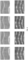
- FIG. 3 There is an optional data augmentation step (operation 11) as illustrated in Figure 3 which may occur before the labeling.
- the data augmentation is any method designed to alter the training data in a way that can provide additional samples of training data.
- the four panels at the top of Figure 3 show a process of random azimuthal shift. Each image is randomly shifted in the horizontal direction, so that the sinusoids that represent the sand layers would appear with different phases.
- this operation is to teach the network that the predicted sand fraction should be invariant as sand layers are inclined to different orientations.
- the random azimuth shift should not change the sand count (F sand ) but will train the machine-learning algorithm to be insensitive to azimuth.
- a depth shift may be applied. This shift is a positive or negative vertical shift. This will affect the sand count dependent on the depth shift.
- This embodiment teaches the machine-learning algorithm that the location of the sand beds is irrelevant.
- a neural network may be constructed at operation 13.
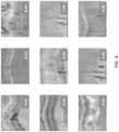
- the neural network may be trained and tested at operation 14, for example using training data like that shown in Figure 4 .
- the training and testing may be done iteratively as shown in Figure 5 .
- the neural network is trained on 85% of the available labeled borehole image log intervals. The remaining 15% is used to test the accuracy of the predicted F sand after each iteration. This iterative process is performed if the accuracy requirements are not met at decision point 16 of method 100, so the neural network is modified at operation 15 and the training and testing are repeated.
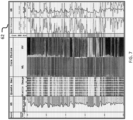
- F sand predictions are shown in Figures 6 and 7 in the vertical tracks labeled 60 and 62, respectively, where the darker line is the predicted F sand from method 100 and the lighter line is a F sand that was estimated by a petrophysicist based on the core.
- the predicted F sand curves are very close to the F sand from the core.
- the trained neural network can then be used with borehole images from other wells in the same area or wells that are drilled in areas that are believed to be similar to the one from which the training data was derived.
- the predicted F sand can then be used in operation 18 for a number of petrophysical analyses.
- FIG. 9 is a block diagram illustrating a borehole image analysis system 500, in accordance with some embodiments. While certain specific features are illustrated, those skilled in the art will appreciate from the present disclosure that various other features have not been illustrated for the sake of brevity and so as not to obscure more pertinent aspects of the embodiments disclosed herein.
- the borehole image analysis system 500 includes one or more processing units (CPUs) 502, one or more network interfaces 508 and/or other communications interfaces 503, memory 506, and one or more communication buses 504 for interconnecting these and various other components.
- the borehole image analysis system 500 also includes a user interface 505 (e.g., a display 505-1 and an input device 505-2).
- the communication buses 504 may include circuitry (sometimes called a chipset) that interconnects and controls communications between system components.
- Memory 506 includes high-speed random access memory, such as DRAM, SRAM, DDR RAM or other random access solid state memory devices; and may include non-volatile memory, such as one or more magnetic disk storage devices, optical disk storage devices, flash memory devices, or other non-volatile solid state storage devices. Memory 506 may optionally include one or more storage devices remotely located from the CPUs 502. Memory 506, including the non-volatile and volatile memory devices within memory 506, comprises a non-transitory computer readable storage medium and may store well logs, borehole images, and processed data products.
- memory 506 or the non-transitory computer readable storage medium of memory 506 stores the following programs, modules and data structures, or a subset thereof including an operating system 516, a network communication module 518, and a borehole image analysis module 520.
- the operating system 516 includes procedures for handling various basic system services and for performing hardware dependent tasks.
- the network communication module 518 facilitates communication with other devices via the communication network interfaces 508 (wired or wireless) and one or more communication networks, such as the Internet, other wide area networks, local area networks, metropolitan area networks, and so on.
- communication network interfaces 508 wireless or wireless
- communication networks such as the Internet, other wide area networks, local area networks, metropolitan area networks, and so on.
- the borehole image analysis module 520 executes the operations of method 100.
- borehole image analysis module 520 may include data sub-module 525, which handles the well logs and borehole images 525-1 through 525-N. This data is supplied by data sub-module 525 to other sub-modules.
- Image preparation sub-module 522 contains a set of instructions 522-1 and accepts metadata and parameters 522-2 that will enable it to execute the division and labeling of the borehole images as described in method 100, and optionally the data augmentation.
- the neural network sub-module 523 contains a set of instructions 523-1 and accepts metadata and parameters 523-2 that will enable it to execute the machine-learning operations of method 100.
- this example labels this module as a neural network, it is within the scope of this invention for any machine-learning algorithm, for example generative adversarial networks (GANs), to be used.
- GANs generative adversarial networks
- the hydrocarbon estimation sub-module 524 contains a set of instructions 524-1 and accepts metadata and parameters 524-2 that will enable it to execute petrophysical analyses such as cumulative sand and hydrocarbon in place for method 100. Although specific operations have been identified for the sub-modules discussed herein, this is not meant to be limiting. Each sub-module may be configured to execute operations identified as being a part of other sub-modules, and may contain other instructions, metadata, and parameters that allow it to execute other operations of use in processing data and generate the graphical image including a F sand prediction. For example, any of the sub-modules may optionally be able to generate a display that would be sent to and shown on the user interface display 505-1. In addition, any of the data or processed data products may be transmitted via the communication interface(s) 503 or the network interface 508 and may be stored in memory 506.
- Method 100 is, optionally, governed by instructions that are stored in computer memory or a non-transitory computer readable storage medium (e.g., memory 506 in Figure 9 ) and are executed by one or more processors (e.g., processors 502) of one or more computer systems.
- the computer readable storage medium may include a magnetic or optical disk storage device, solid state storage devices such as flash memory, or other non-volatile memory device or devices.
- the computer readable instructions stored on the computer readable storage medium may include one or more of: source code, assembly language code, object code, or another instruction format that is interpreted by one or more processors.
- some operations in each method may be combined and/or the order of some operations may be changed from the order shown in the figures.
- method 100 is described as being performed by a computer system, although in some embodiments, various operations of method 100 are distributed across separate computer systems.
- the term “if” may be construed to mean “when” or “upon” or “in response to determining” or “in accordance with a determination” or “in response to detecting,” that a stated condition precedent is true, depending on the context.
- the phrase “if it is determined [that a stated condition precedent is true]” or “if [a stated condition precedent is true]” or “when [a stated condition precedent is true]” may be construed to mean “upon determining” or “in response to determining” or “in accordance with a determination” or “upon detecting” or “in response to detecting” that the stated condition precedent is true, depending on the context.
- stages that are not order dependent may be reordered and other stages may be combined or broken out. While some reordering or other groupings are specifically mentioned, others will be obvious to those of ordinary skill in the art and so do not present an exhaustive list of alternatives. Moreover, it should be recognized that the stages could be implemented in hardware, firmware, software or any combination thereof.
Landscapes
- Engineering & Computer Science (AREA)
- Physics & Mathematics (AREA)
- Theoretical Computer Science (AREA)
- General Physics & Mathematics (AREA)
- Software Systems (AREA)
- Life Sciences & Earth Sciences (AREA)
- Computing Systems (AREA)
- Artificial Intelligence (AREA)
- Mathematical Physics (AREA)
- Data Mining & Analysis (AREA)
- Evolutionary Computation (AREA)
- General Engineering & Computer Science (AREA)
- Biophysics (AREA)
- Molecular Biology (AREA)
- General Health & Medical Sciences (AREA)
- Computational Linguistics (AREA)
- Biomedical Technology (AREA)
- Health & Medical Sciences (AREA)
- Computer Vision & Pattern Recognition (AREA)
- General Life Sciences & Earth Sciences (AREA)
- Geophysics (AREA)
- Quality & Reliability (AREA)
- Medical Informatics (AREA)
- Geophysics And Detection Of Objects (AREA)
- Image Analysis (AREA)
Description
- <DELETED>
- <DELETED>
- The disclosed embodiments relate generally to techniques for quantitative analysis of borehole images obtained from a wellbore through a subsurface volume of interest and, in particular, to a method of estimating net sand in a formation traversed by a wellbore by analysis of borehole images from the wellbore.
- Deepwater reservoirs often consist of highly laminated sand-shale sequences, where individual beds are too fine to be fully resolved by standard logs. Note that as is understood in the art, the term sand may refer to sandstone. Without appropriate characterization, thin beds could be under-estimated or neglected, which leads to pessimistic predictions on hydrocarbon pore volume and well deliverability, and reservoir quality is routinely under-predicted. Consequently, laminated reservoirs are considered a common struggle for petrophysical analysis.
- To characterize the thin beds with better accuracy, one could take advantage of high-resolution borehole images, which can detect extremely small formation features (e.g., millimeter scale). In traditional thin-bed analysis, sand counting is usually done by applying a user-specified cutoff on a 1-D high-resolution curve extracted from borehole images. The workflow generally requires meticulous image QC, multiple pre-processing steps and log calibration, and the results are often highly sensitive to the cutoff selection. Moreover, due to the uncalibrated nature of borehole imaging tools, cutoffs selected in one well are not necessarily applicable to other wells, even if they share the same formation systems. This has prevented consistent standards while evaluating multiple wells in one field or asset. Reference may be made to
WO 01/31365 A1 WO 2015/127349 A1 which relates to systems, methods, and computer medium to produce efficient, consistent, and high-confidence image-based electrofacies analysis in stratigraphic interpretations across multiple wells. Reference may be made toWO 2014/070572 A2 which relates to rock facies prediction in non-cored wells from cored wells. - The ability to define the location and quantity of hydrocarbons in the subsurface is crucial to our ability to make the most appropriate choices for purchasing materials, operating safely, and successfully completing projects. Project cost is dependent upon accurate prediction of the position of physical boundaries within the Earth. Decisions include, but are not limited to, budgetary planning, obtaining mineral and lease rights, signing well commitments, permitting rig locations, designing well paths and drilling strategy, preventing subsurface integrity issues by planning proper casing and cementation strategies, and selecting and purchasing appropriate completion and production equipment.
- There exists a need for improved characterization of thin beds in the subsurface to allow improved quantification of hydrocarbons in place in subsurface reservoirs.
- A method of borehole image analysis according to the present invention is defined in
claim 1. Specific embodiments are defined in the dependent claims. - In another aspect of the present invention, to address the aforementioned problems, some embodiments provide a non-transitory computer readable storage medium storing one or more programs as defined in claim 8. The one or more programs comprise instructions, which when executed by a computer system with one or more processors and memory, cause the computer system to perform any of the methods provided herein.
- In yet another aspect of the present invention, to address the aforementioned problems, some embodiments provide a computer system as defined in claim 7. The computer system includes one or more processors, memory, and one or more programs. The one or more programs are stored in memory and configured to be executed by the one or more processors. The one or more programs include instructions that when executed by the one or more processors cause the computer system to perform any of the methods provided herein as defined in claim 6.
-
-
Figure 1 illustrates a flowchart of a method of borehole image analysis, in accordance with some embodiments: -
Figure 2 illustrates a step of an embodiment; -
Figure 3 illustrates a step of an embodiment; -
Figure 4 illustrates a step of an embodiment; -
Figure 5 illustrates a step of an embodiment; -
Figure 6 illustrates a graphical display produced by an embodiment including a result of an embodiment; -
Figure 7 illustrates a graphical display produced by an embodiment including a result of an embodiment; -
Figure 8 compares a result of an embodiment with the expected answer; and -
Figure 9 is a block diagram illustrating a borehole image analysis system, in accordance with some embodiments. - Like reference numerals refer to corresponding parts throughout the drawings.
- Described below are methods, systems, and computer readable storage media that provide a manner of analyzing borehole images. These embodiments are designed to be of particular use for borehole image analysis in areas with thin sand beds.
- Reference will now be made in detail to various embodiments, examples of which are illustrated in the accompanying drawings. In the following detailed description, numerous specific details are set forth in order to provide a thorough understanding of the present disclosure and the embodiments described herein. However, embodiments described herein may be practiced without these specific details. In other instances, well-known methods, procedures, components, and mechanical apparatus have not been described in detail so as not to unnecessarily obscure aspects of the embodiments.
- The embodiments described herein for borehole image analysis provide ways to generate a Fraction of Sand (Fsand) estimate and net-to-gross (NTG) estimate of sand in a formation using a machine-learning algorithm such as a neural network. Compared to conventional methods for estimating sand in a formation with borehole images, such as applying cut-offs on an extracted resistivity log, the embodiments provided herein take full advantage of borehole images as 2D arrays, which reduces uncertainties caused by image calibration, thin-bed effect, etc.; furthermore, the embodiments herein do not require image flattening, pad equalization or averaging; and make non-linear differentiation between sand and non-sand, which better reflects the complexity of real formations. The predicted Fsand, which has a higher resolution than what could be derived from standard well logs like Gamma Ray, can be integrated with other logs for petrophysical and geological analysis. Additionally, the machine-learning algorithm, once trained, can be applied to additional wells in a field more reliably compared with conventional resistivity cut-off methods.
-
Figure 1 illustrates a flowchart of an embodiment of amethod 100 for estimating Fsand from borehole images in order to perform petrophysical analysis and/or estimate hydrocarbons in a formation. The method begins by receiving at least one borehole image at native resolution (usually 0.2 - 1.2 inch with 1 inch = 2.54 cm) which is divided into smaller intervals atoperation 10. The divided images are labeled with sand fractions identified from cores atoperation 12. This is illustrated inFigure 2. Figure 2 includes a depth column, aborehole image log 21, a White Light (WL)core photo 23, an Ultraviolet (UV)core photo 24, and a track highlighting sand intervals identified from core called asand flag track 22. InFigure 2 , theborehole image log 21 has four intervals selected (21A, 21B, 21C, 21D) and thesand flag track 22 has corresponding intervals (22A, 22B, 22C, 22D) with their sand fractions (0.3, 1.0, 0.5, and 0.0, respectively). Thesand flag track 22 may be developed from photos of a core such as the WL and UV photos, physical inspection of a core, or any other method for estimating sand fraction (Fsand) for depth intervals. The sand fractions fromsand flag track 22 are used to label the selected intervals in theborehole image log 21 atoperation 12 ofmethod 100. Although this example has four selected intervals, in some embodiments there may be fewer or more intervals as needed in order to characterize the range of sand fractions in the well. There is an optional data augmentation step (operation 11) as illustrated inFigure 3 which may occur before the labeling. The data augmentation is any method designed to alter the training data in a way that can provide additional samples of training data. For example, the four panels at the top ofFigure 3 show a process of random azimuthal shift. Each image is randomly shifted in the horizontal direction, so that the sinusoids that represent the sand layers would appear with different phases. As sinusoidal phase on borehole image is interpreted as orientation of sheet-like geological features (bed boundaries, fractures, deformation bands, etc.), this operation is to teach the network that the predicted sand fraction should be invariant as sand layers are inclined to different orientations. The random azimuth shift should not change the sand count (Fsand) but will train the machine-learning algorithm to be insensitive to azimuth. In another embodiment shown in the four panels at the bottom ofFigure 3 , a depth shift may be applied. This shift is a positive or negative vertical shift. This will affect the sand count dependent on the depth shift. This embodiment teaches the machine-learning algorithm that the location of the sand beds is irrelevant. These examples of data augmentation are not meant to be limiting; any process that can be applied to the training data samples to generate additional likely images is within the scope of this invention such as stretching, rotation, flipping, cropping, and the like. - The method then moves on to the machine-learning steps. Here, by way of example and not limitation, a neural network may be constructed at
operation 13. The neural network may be trained and tested atoperation 14, for example using training data like that shown inFigure 4 . The training and testing may be done iteratively as shown inFigure 5 . In the example ofFigure 5 , the neural network is trained on 85% of the available labeled borehole image log intervals. The remaining 15% is used to test the accuracy of the predicted Fsand after each iteration. This iterative process is performed if the accuracy requirements are not met atdecision point 16 ofmethod 100, so the neural network is modified atoperation 15 and the training and testing are repeated. InFigure 5 , after 3 iterations the accuracy is R=0.53481 and the crossplot of the predicted Fsand versus the Fsand from core shows a cloud of points with no clear trend. A perfect result would have R=1.0 and a trend exactly matching 1:1 in the crossplot. After 42 iterations, the accuracy has improved to R=0.71818 and after 85 iterations the accuracy has improved to R=0.82461. The determination of whether the result is accurate enough may be done with a user-defined threshold or by allowing the machine-learning algorithm to identify it. Once the accuracy requirements are met, the neural network can be used to make Fsand predictions atoperation 17. These Fsand predictions are shown inFigures 6 and7 in the vertical tracks labeled 60 and 62, respectively, where the darker line is the predicted Fsand frommethod 100 and the lighter line is a Fsand that was estimated by a petrophysicist based on the core. The predicted Fsand curves are very close to the Fsand from the core. The trained neural network can then be used with borehole images from other wells in the same area or wells that are drilled in areas that are believed to be similar to the one from which the training data was derived. - Referring again to
Figure 1 , the predicted Fsand can then be used inoperation 18 for a number of petrophysical analyses. For example, cumulative sand in a formation or an interval can be calculated by summing up the Fsand values foot by foot (1 foot = 30.48 cm) is shown inFigure 8 . Hydrocarbon in place can then be calculated through equation HCIP = A×hc ×φ× (1 - Sw)/B, where HCIP is hydrocarbon in place, A is the area of the reservoir, hc is cumulative sand thickness (net sand thickness), φ is the porosity of the net sand, Sw is the water saturation of the net sand, and B is the formation volume factor. This will impact decisions on where to drill, optimal wellpaths, and how to complete wells. -
Figure 9 is a block diagram illustrating a boreholeimage analysis system 500, in accordance with some embodiments. While certain specific features are illustrated, those skilled in the art will appreciate from the present disclosure that various other features have not been illustrated for the sake of brevity and so as not to obscure more pertinent aspects of the embodiments disclosed herein. - To that end, the borehole
image analysis system 500 includes one or more processing units (CPUs) 502, one ormore network interfaces 508 and/orother communications interfaces 503,memory 506, and one ormore communication buses 504 for interconnecting these and various other components. The boreholeimage analysis system 500 also includes a user interface 505 (e.g., a display 505-1 and an input device 505-2). Thecommunication buses 504 may include circuitry (sometimes called a chipset) that interconnects and controls communications between system components.Memory 506 includes high-speed random access memory, such as DRAM, SRAM, DDR RAM or other random access solid state memory devices; and may include non-volatile memory, such as one or more magnetic disk storage devices, optical disk storage devices, flash memory devices, or other non-volatile solid state storage devices.Memory 506 may optionally include one or more storage devices remotely located from theCPUs 502.Memory 506, including the non-volatile and volatile memory devices withinmemory 506, comprises a non-transitory computer readable storage medium and may store well logs, borehole images, and processed data products. - In some embodiments,
memory 506 or the non-transitory computer readable storage medium ofmemory 506 stores the following programs, modules and data structures, or a subset thereof including anoperating system 516, anetwork communication module 518, and a boreholeimage analysis module 520. - The
operating system 516 includes procedures for handling various basic system services and for performing hardware dependent tasks. - The
network communication module 518 facilitates communication with other devices via the communication network interfaces 508 (wired or wireless) and one or more communication networks, such as the Internet, other wide area networks, local area networks, metropolitan area networks, and so on. - In some embodiments, the borehole
image analysis module 520 executes the operations ofmethod 100. boreholeimage analysis module 520 may include data sub-module 525, which handles the well logs and borehole images 525-1 through 525-N. This data is supplied by data sub-module 525 to other sub-modules. - Image preparation sub-module 522 contains a set of instructions 522-1 and accepts metadata and parameters 522-2 that will enable it to execute the division and labeling of the borehole images as described in
method 100, and optionally the data augmentation. Theneural network sub-module 523 contains a set of instructions 523-1 and accepts metadata and parameters 523-2 that will enable it to execute the machine-learning operations ofmethod 100. Although this example labels this module as a neural network, it is within the scope of this invention for any machine-learning algorithm, for example generative adversarial networks (GANs), to be used. Thehydrocarbon estimation sub-module 524 contains a set of instructions 524-1 and accepts metadata and parameters 524-2 that will enable it to execute petrophysical analyses such as cumulative sand and hydrocarbon in place formethod 100. Although specific operations have been identified for the sub-modules discussed herein, this is not meant to be limiting. Each sub-module may be configured to execute operations identified as being a part of other sub-modules, and may contain other instructions, metadata, and parameters that allow it to execute other operations of use in processing data and generate the graphical image including a Fsand prediction. For example, any of the sub-modules may optionally be able to generate a display that would be sent to and shown on the user interface display 505-1. In addition, any of the data or processed data products may be transmitted via the communication interface(s) 503 or thenetwork interface 508 and may be stored inmemory 506. -
Method 100 is, optionally, governed by instructions that are stored in computer memory or a non-transitory computer readable storage medium (e.g.,memory 506 inFigure 9 ) and are executed by one or more processors (e.g., processors 502) of one or more computer systems. The computer readable storage medium may include a magnetic or optical disk storage device, solid state storage devices such as flash memory, or other non-volatile memory device or devices. The computer readable instructions stored on the computer readable storage medium may include one or more of: source code, assembly language code, object code, or another instruction format that is interpreted by one or more processors. In various embodiments, some operations in each method may be combined and/or the order of some operations may be changed from the order shown in the figures. For ease of explanation,method 100 is described as being performed by a computer system, although in some embodiments, various operations ofmethod 100 are distributed across separate computer systems. - While particular embodiments are described above, it will be understood it is not intended to limit the invention to these particular embodiments insofar as they fall within the scope of the invention as set forth in the accompanying claims. Numerous specific details are set forth in order to provide a thorough understanding of the subject matter presented herein. But it will be apparent to one of ordinary skill in the art that the subject matter may be practiced (within the scope of the claims) without these specific details. In other instances, well-known methods, procedures, components, and circuits have not been described in detail so as not to unnecessarily obscure aspects of the embodiments.
- The terminology used in the description of the invention herein is for the purpose of describing particular embodiments only and is not intended to be limiting of the invention. As used in the description of the invention and the appended claims, the singular forms "a," "an," and "the" are intended to include the plural forms as well, unless the context clearly indicates otherwise. It will also be understood that the term "and/or" as used herein refers to and encompasses any and all possible combinations of one or more of the associated listed items. It will be further understood that the terms "includes," "including," "comprises," and/or "comprising," when used in this specification, specify the presence of stated features, operations, elements, and/or components, but do not preclude the presence or addition of one or more other features, operations, elements, components, and/or groups thereof.
- As used herein, the term "if" may be construed to mean "when" or "upon" or "in response to determining" or "in accordance with a determination" or "in response to detecting," that a stated condition precedent is true, depending on the context. Similarly, the phrase "if it is determined [that a stated condition precedent is true]" or "if [a stated condition precedent is true]" or "when [a stated condition precedent is true]" may be construed to mean "upon determining" or "in response to determining" or "in accordance with a determination" or "upon detecting" or "in response to detecting" that the stated condition precedent is true, depending on the context.
- Although some of the various drawings illustrate a number of logical stages in a particular order, stages that are not order dependent may be reordered and other stages may be combined or broken out. While some reordering or other groupings are specifically mentioned, others will be obvious to those of ordinary skill in the art and so do not present an exhaustive list of alternatives. Moreover, it should be recognized that the stages could be implemented in hardware, firmware, software or any combination thereof.
- The foregoing description, for purpose of explanation, has been described with were chosen and described in order to best explain the principles of the invention and its practical applications, to thereby enable others skilled in the art to best utilize the invention.
Claims (8)
- A computer-implemented method comprising:a. receiving, at one or more computer processors, a borehole image, wherein the borehole image traverses a subsurface formation including sand and non-sand layers;b. dividing (10), via the one or more computer processors, the borehole image into multiple divided borehole images, wherein each divided borehole image traverses a depth interval of the subsurface formation;c. selecting, via the one or more computer processors, a subset of the multiple divided borehole images for use as training data; characterized in that it further comprises the steps of:d. labeling (12), via the one or more computer processors, the subset of the multiple divided borehole images with sand fraction values based on core analysis such that each depth interval has a corresponding sand fraction value, each sand fraction value being a fraction of the corresponding depth interval that is sand;e. training (14), via the one or more computer processors, a neural network to predict a sand fraction value using the subset of the multiple divided borehole images labelled with sand fraction values, the training generating a trained neural network; andf. predicting (17), via the one or more computer processors, a sand fraction value of a further borehole image of a subsurface volume using the trained neural network.
- The method of claim 1 further comprising augmenting (11) the training data prior to the labeling.
- The method of claim 2 wherein the augmenting (11) the training data includes azimuthal shifts.
- The method of claim 2 wherein the augmenting (11) the training data includes depth shifts.
- The method of claim 1 further comprising using the predicted sand fraction value to estimate (18) at least one of cumulative sand and hydrocarbon in place.
- One or more computer programs comprising instructions which, when executed by a computer, cause the computer to carry out the method of any of claims 1 to 5.
- A computer system (500) comprising:one or more processors (502); andmemory (506),wherein one or more computer programs are stored in the memory (506) and configured to be executed by the one or more processors (502), the one or more programs including instructions that when executed by the one or more processors (502) cause the computer system to carry out the method of any of claims 1 to 5.
- A non-transitory computer readable storage medium having the one or more programs of claim 6 stored thereon.
Applications Claiming Priority (2)
| Application Number | Priority Date | Filing Date | Title |
|---|---|---|---|
| US201862750623P | 2018-10-25 | 2018-10-25 | |
| PCT/IB2019/058764 WO2020084387A1 (en) | 2018-10-25 | 2019-10-15 | System and method for quantitative analysis of borehole images |
Publications (2)
| Publication Number | Publication Date |
|---|---|
| EP3871019A1 EP3871019A1 (en) | 2021-09-01 |
| EP3871019B1 true EP3871019B1 (en) | 2024-08-28 |
Family
ID=68296585
Family Applications (1)
| Application Number | Title | Priority Date | Filing Date |
|---|---|---|---|
| EP19790839.5A Active EP3871019B1 (en) | 2018-10-25 | 2019-10-15 | System and method for quantitative analysis of borehole images |
Country Status (4)
| Country | Link |
|---|---|
| US (1) | US10997705B2 (en) |
| EP (1) | EP3871019B1 (en) |
| AU (1) | AU2019367605A1 (en) |
| WO (1) | WO2020084387A1 (en) |
Families Citing this family (5)
| Publication number | Priority date | Publication date | Assignee | Title |
|---|---|---|---|---|
| BR112022025927A2 (en) | 2020-06-24 | 2023-03-14 | Shell Int Research | METHOD FOR PREDICTING THE OCCURRENCE OF A GEOLOGICAL FEATURE IN A WELL IMAGE PROFILE |
| BR112022025666A2 (en) * | 2020-06-26 | 2023-01-17 | Shell Int Research | METHOD FOR PREDICTING THE OCCURRENCE OF A STRUCTURAL FEATURE IN A TESTIMONY IMAGE |
| US11898435B2 (en) * | 2020-09-25 | 2024-02-13 | Halliburton Energy Services, Inc. | Correcting borehole images using machine-learning models |
| FR3132320B1 (en) * | 2022-01-28 | 2024-02-02 | Services Petroliers Schlumberger | DETECTION AND CORRECTION OF POSITIVE FALSE CLASSIFICATIONS FROM A PRODUCT SAND DETECTION TOOL |
| JP2023180661A (en) * | 2022-06-10 | 2023-12-21 | 株式会社大林組 | Soil quality estimation device, soil quality estimation method, and soil quality estimation program |
Family Cites Families (10)
| Publication number | Priority date | Publication date | Assignee | Title |
|---|---|---|---|---|
| US5251286A (en) | 1992-03-16 | 1993-10-05 | Texaco, Inc. | Method for estimating formation permeability from wireline logs using neural networks |
| FR2738871B1 (en) | 1995-09-19 | 1997-11-14 | Elf Aquitaine | PROCESS FOR REALIZING THE TEXTURES OF A GEOLOGICAL STRUCTURE |
| FR2772486B1 (en) | 1997-12-15 | 2000-01-07 | Elf Exploration Prod | METHOD FOR THE AUTOMATIC DETECTION OF PLANAR HETEROGENEITIES INTERRUPTING THE LAMINATION OF A MEDIUM |
| US6337568B1 (en) | 1999-10-25 | 2002-01-08 | Tarek A. Tutunji | System and method for enhanced vertical resolution magnetic resonance imaging logs |
| US6381542B1 (en) | 2000-04-05 | 2002-04-30 | Baker Hughes Incorporated | Generic, accurate, and real time borehole correction for resistivity tools |
| US6928367B2 (en) * | 2002-09-27 | 2005-08-09 | Veritas Dgc Inc. | Reservoir fracture characterization |
| US7814036B2 (en) | 2003-06-19 | 2010-10-12 | Haliburton Energy Services, Inc. | Processing well logging data with neural network |
| US8417495B2 (en) | 2007-11-07 | 2013-04-09 | Baker Hughes Incorporated | Method of training neural network models and using same for drilling wellbores |
| US20140149041A1 (en) | 2012-10-29 | 2014-05-29 | Saudi Arabian Oil Company | Rock facies prediction in non-cored wells from cored wells |
| US9939548B2 (en) * | 2014-02-24 | 2018-04-10 | Saudi Arabian Oil Company | Systems, methods, and computer medium to produce efficient, consistent, and high-confidence image-based electrofacies analysis in stratigraphic interpretations across multiple wells |
-
2019
- 2019-10-15 WO PCT/IB2019/058764 patent/WO2020084387A1/en not_active Ceased
- 2019-10-15 AU AU2019367605A patent/AU2019367605A1/en not_active Abandoned
- 2019-10-15 EP EP19790839.5A patent/EP3871019B1/en active Active
- 2019-10-15 US US16/601,818 patent/US10997705B2/en active Active
Also Published As
| Publication number | Publication date |
|---|---|
| AU2019367605A1 (en) | 2021-03-11 |
| US20200134803A1 (en) | 2020-04-30 |
| EP3871019A1 (en) | 2021-09-01 |
| WO2020084387A1 (en) | 2020-04-30 |
| US10997705B2 (en) | 2021-05-04 |
Similar Documents
| Publication | Publication Date | Title |
|---|---|---|
| US10997705B2 (en) | System and method for quantitative analysis of borehole images | |
| US10991078B2 (en) | Inferring petrophysical properties of hydrocarbon reservoirs using a neural network | |
| AU2014357611B2 (en) | Digital core model construction | |
| EP3077618B1 (en) | Tuning digital core analysis to laboratory results | |
| US20190227185A1 (en) | System and method for predicting fault seal from seismic data | |
| US20130325349A1 (en) | Methods for Generating Depofacies Classifications for Subsurface Oil or Gas Reservoirs or Fields | |
| US20150241591A1 (en) | Systems, methods, and computer medium to produce efficient, consistent, and high-confidence image-based electrofacies analysis in stratigraphic interpretations across multiple wells | |
| US20180341034A1 (en) | System and method for predicting fault seal from seismic data | |
| CA3002673A1 (en) | System and method for modeling coupled systems of hydrodynamics and sediment transport | |
| AU2021252214A1 (en) | System and method for seismic inversion | |
| US11754736B2 (en) | System and method for classifying seismic data by integrating petrophysical data | |
| WO2018027003A1 (en) | System and method for petro-elastic modeling | |
| CN113227529A (en) | System and method for automated post-geosteering | |
| AU2021215052B2 (en) | Categorizng fractures in a subsurface formation | |
| Ling et al. | Deep transient testing with a complete digital workflow in South-East Asia Green Fields | |
| Petrov et al. | ML Driven Integrated Approach for Perforation Interval Selection Based on Advanced Borehole Images AI Assisted Interpretation | |
| Girinathan et al. | Role of Al-Driven Reservoir Characterization in Critical Operational Decision-Making: An Onshore UAE Case Study |
Legal Events
| Date | Code | Title | Description |
|---|---|---|---|
| STAA | Information on the status of an ep patent application or granted ep patent |
Free format text: STATUS: UNKNOWN |
|
| STAA | Information on the status of an ep patent application or granted ep patent |
Free format text: STATUS: THE INTERNATIONAL PUBLICATION HAS BEEN MADE |
|
| PUAI | Public reference made under article 153(3) epc to a published international application that has entered the european phase |
Free format text: ORIGINAL CODE: 0009012 |
|
| STAA | Information on the status of an ep patent application or granted ep patent |
Free format text: STATUS: REQUEST FOR EXAMINATION WAS MADE |
|
| 17P | Request for examination filed |
Effective date: 20210222 |
|
| AK | Designated contracting states |
Kind code of ref document: A1 Designated state(s): AL AT BE BG CH CY CZ DE DK EE ES FI FR GB GR HR HU IE IS IT LI LT LU LV MC MK MT NL NO PL PT RO RS SE SI SK SM TR |
|
| DAV | Request for validation of the european patent (deleted) | ||
| DAX | Request for extension of the european patent (deleted) | ||
| STAA | Information on the status of an ep patent application or granted ep patent |
Free format text: STATUS: EXAMINATION IS IN PROGRESS |
|
| 17Q | First examination report despatched |
Effective date: 20221205 |
|
| P01 | Opt-out of the competence of the unified patent court (upc) registered |
Effective date: 20230522 |
|
| GRAP | Despatch of communication of intention to grant a patent |
Free format text: ORIGINAL CODE: EPIDOSNIGR1 |
|
| STAA | Information on the status of an ep patent application or granted ep patent |
Free format text: STATUS: GRANT OF PATENT IS INTENDED |
|
| INTG | Intention to grant announced |
Effective date: 20240513 |
|
| GRAS | Grant fee paid |
Free format text: ORIGINAL CODE: EPIDOSNIGR3 |
|
| GRAA | (expected) grant |
Free format text: ORIGINAL CODE: 0009210 |
|
| STAA | Information on the status of an ep patent application or granted ep patent |
Free format text: STATUS: THE PATENT HAS BEEN GRANTED |
|
| AK | Designated contracting states |
Kind code of ref document: B1 Designated state(s): AL AT BE BG CH CY CZ DE DK EE ES FI FR GB GR HR HU IE IS IT LI LT LU LV MC MK MT NL NO PL PT RO RS SE SI SK SM TR |
|
| RAP3 | Party data changed (applicant data changed or rights of an application transferred) |
Owner name: CHEVRON U.S.A. INC. |
|
| REG | Reference to a national code |
Ref country code: GB Ref legal event code: FG4D |
|
| REG | Reference to a national code |
Ref country code: CH Ref legal event code: EP |
|
| REG | Reference to a national code |
Ref country code: NL Ref legal event code: FP |
|
| REG | Reference to a national code |
Ref country code: DE Ref legal event code: R096 Ref document number: 602019057947 Country of ref document: DE |
|
| REG | Reference to a national code |
Ref country code: IE Ref legal event code: FG4D |
|
| REG | Reference to a national code |
Ref country code: LT Ref legal event code: MG9D |
|
| REG | Reference to a national code |
Ref country code: AT Ref legal event code: MK05 Ref document number: 1718567 Country of ref document: AT Kind code of ref document: T Effective date: 20240828 |
|
| PG25 | Lapsed in a contracting state [announced via postgrant information from national office to epo] |
Ref country code: FI Free format text: LAPSE BECAUSE OF FAILURE TO SUBMIT A TRANSLATION OF THE DESCRIPTION OR TO PAY THE FEE WITHIN THE PRESCRIBED TIME-LIMIT Effective date: 20240828 Ref country code: GR Free format text: LAPSE BECAUSE OF FAILURE TO SUBMIT A TRANSLATION OF THE DESCRIPTION OR TO PAY THE FEE WITHIN THE PRESCRIBED TIME-LIMIT Effective date: 20241129 Ref country code: PL Free format text: LAPSE BECAUSE OF FAILURE TO SUBMIT A TRANSLATION OF THE DESCRIPTION OR TO PAY THE FEE WITHIN THE PRESCRIBED TIME-LIMIT Effective date: 20240828 Ref country code: PT Free format text: LAPSE BECAUSE OF FAILURE TO SUBMIT A TRANSLATION OF THE DESCRIPTION OR TO PAY THE FEE WITHIN THE PRESCRIBED TIME-LIMIT Effective date: 20241230 |
|
| PG25 | Lapsed in a contracting state [announced via postgrant information from national office to epo] |
Ref country code: BG Free format text: LAPSE BECAUSE OF FAILURE TO SUBMIT A TRANSLATION OF THE DESCRIPTION OR TO PAY THE FEE WITHIN THE PRESCRIBED TIME-LIMIT Effective date: 20240828 |
|
| PG25 | Lapsed in a contracting state [announced via postgrant information from national office to epo] |
Ref country code: LV Free format text: LAPSE BECAUSE OF FAILURE TO SUBMIT A TRANSLATION OF THE DESCRIPTION OR TO PAY THE FEE WITHIN THE PRESCRIBED TIME-LIMIT Effective date: 20240828 |
|
| PG25 | Lapsed in a contracting state [announced via postgrant information from national office to epo] |
Ref country code: AT Free format text: LAPSE BECAUSE OF FAILURE TO SUBMIT A TRANSLATION OF THE DESCRIPTION OR TO PAY THE FEE WITHIN THE PRESCRIBED TIME-LIMIT Effective date: 20240828 Ref country code: IS Free format text: LAPSE BECAUSE OF FAILURE TO SUBMIT A TRANSLATION OF THE DESCRIPTION OR TO PAY THE FEE WITHIN THE PRESCRIBED TIME-LIMIT Effective date: 20241228 |
|
| PG25 | Lapsed in a contracting state [announced via postgrant information from national office to epo] |
Ref country code: HR Free format text: LAPSE BECAUSE OF FAILURE TO SUBMIT A TRANSLATION OF THE DESCRIPTION OR TO PAY THE FEE WITHIN THE PRESCRIBED TIME-LIMIT Effective date: 20240828 |
|
| PG25 | Lapsed in a contracting state [announced via postgrant information from national office to epo] |
Ref country code: RS Free format text: LAPSE BECAUSE OF FAILURE TO SUBMIT A TRANSLATION OF THE DESCRIPTION OR TO PAY THE FEE WITHIN THE PRESCRIBED TIME-LIMIT Effective date: 20241128 Ref country code: ES Free format text: LAPSE BECAUSE OF FAILURE TO SUBMIT A TRANSLATION OF THE DESCRIPTION OR TO PAY THE FEE WITHIN THE PRESCRIBED TIME-LIMIT Effective date: 20240828 |
|
| PG25 | Lapsed in a contracting state [announced via postgrant information from national office to epo] |
Ref country code: RS Free format text: LAPSE BECAUSE OF FAILURE TO SUBMIT A TRANSLATION OF THE DESCRIPTION OR TO PAY THE FEE WITHIN THE PRESCRIBED TIME-LIMIT Effective date: 20241128 Ref country code: PT Free format text: LAPSE BECAUSE OF FAILURE TO SUBMIT A TRANSLATION OF THE DESCRIPTION OR TO PAY THE FEE WITHIN THE PRESCRIBED TIME-LIMIT Effective date: 20241230 Ref country code: PL Free format text: LAPSE BECAUSE OF FAILURE TO SUBMIT A TRANSLATION OF THE DESCRIPTION OR TO PAY THE FEE WITHIN THE PRESCRIBED TIME-LIMIT Effective date: 20240828 Ref country code: LV Free format text: LAPSE BECAUSE OF FAILURE TO SUBMIT A TRANSLATION OF THE DESCRIPTION OR TO PAY THE FEE WITHIN THE PRESCRIBED TIME-LIMIT Effective date: 20240828 Ref country code: IS Free format text: LAPSE BECAUSE OF FAILURE TO SUBMIT A TRANSLATION OF THE DESCRIPTION OR TO PAY THE FEE WITHIN THE PRESCRIBED TIME-LIMIT Effective date: 20241228 Ref country code: HR Free format text: LAPSE BECAUSE OF FAILURE TO SUBMIT A TRANSLATION OF THE DESCRIPTION OR TO PAY THE FEE WITHIN THE PRESCRIBED TIME-LIMIT Effective date: 20240828 Ref country code: GR Free format text: LAPSE BECAUSE OF FAILURE TO SUBMIT A TRANSLATION OF THE DESCRIPTION OR TO PAY THE FEE WITHIN THE PRESCRIBED TIME-LIMIT Effective date: 20241129 Ref country code: FI Free format text: LAPSE BECAUSE OF FAILURE TO SUBMIT A TRANSLATION OF THE DESCRIPTION OR TO PAY THE FEE WITHIN THE PRESCRIBED TIME-LIMIT Effective date: 20240828 Ref country code: ES Free format text: LAPSE BECAUSE OF FAILURE TO SUBMIT A TRANSLATION OF THE DESCRIPTION OR TO PAY THE FEE WITHIN THE PRESCRIBED TIME-LIMIT Effective date: 20240828 Ref country code: BG Free format text: LAPSE BECAUSE OF FAILURE TO SUBMIT A TRANSLATION OF THE DESCRIPTION OR TO PAY THE FEE WITHIN THE PRESCRIBED TIME-LIMIT Effective date: 20240828 Ref country code: AT Free format text: LAPSE BECAUSE OF FAILURE TO SUBMIT A TRANSLATION OF THE DESCRIPTION OR TO PAY THE FEE WITHIN THE PRESCRIBED TIME-LIMIT Effective date: 20240828 |
|
| PG25 | Lapsed in a contracting state [announced via postgrant information from national office to epo] |
Ref country code: RO Free format text: LAPSE BECAUSE OF FAILURE TO SUBMIT A TRANSLATION OF THE DESCRIPTION OR TO PAY THE FEE WITHIN THE PRESCRIBED TIME-LIMIT Effective date: 20240828 Ref country code: DK Free format text: LAPSE BECAUSE OF FAILURE TO SUBMIT A TRANSLATION OF THE DESCRIPTION OR TO PAY THE FEE WITHIN THE PRESCRIBED TIME-LIMIT Effective date: 20240828 Ref country code: SM Free format text: LAPSE BECAUSE OF FAILURE TO SUBMIT A TRANSLATION OF THE DESCRIPTION OR TO PAY THE FEE WITHIN THE PRESCRIBED TIME-LIMIT Effective date: 20240828 |
|
| PG25 | Lapsed in a contracting state [announced via postgrant information from national office to epo] |
Ref country code: EE Free format text: LAPSE BECAUSE OF FAILURE TO SUBMIT A TRANSLATION OF THE DESCRIPTION OR TO PAY THE FEE WITHIN THE PRESCRIBED TIME-LIMIT Effective date: 20240828 |
|
| PG25 | Lapsed in a contracting state [announced via postgrant information from national office to epo] |
Ref country code: CZ Free format text: LAPSE BECAUSE OF FAILURE TO SUBMIT A TRANSLATION OF THE DESCRIPTION OR TO PAY THE FEE WITHIN THE PRESCRIBED TIME-LIMIT Effective date: 20240828 |
|
| PG25 | Lapsed in a contracting state [announced via postgrant information from national office to epo] |
Ref country code: IT Free format text: LAPSE BECAUSE OF FAILURE TO SUBMIT A TRANSLATION OF THE DESCRIPTION OR TO PAY THE FEE WITHIN THE PRESCRIBED TIME-LIMIT Effective date: 20240828 Ref country code: SK Free format text: LAPSE BECAUSE OF FAILURE TO SUBMIT A TRANSLATION OF THE DESCRIPTION OR TO PAY THE FEE WITHIN THE PRESCRIBED TIME-LIMIT Effective date: 20240828 |
|
| REG | Reference to a national code |
Ref country code: DE Ref legal event code: R119 Ref document number: 602019057947 Country of ref document: DE |
|
| REG | Reference to a national code |
Ref country code: CH Ref legal event code: PL |
|
| PLBE | No opposition filed within time limit |
Free format text: ORIGINAL CODE: 0009261 |
|
| STAA | Information on the status of an ep patent application or granted ep patent |
Free format text: STATUS: NO OPPOSITION FILED WITHIN TIME LIMIT |
|
| PG25 | Lapsed in a contracting state [announced via postgrant information from national office to epo] |
Ref country code: MC Free format text: LAPSE BECAUSE OF FAILURE TO SUBMIT A TRANSLATION OF THE DESCRIPTION OR TO PAY THE FEE WITHIN THE PRESCRIBED TIME-LIMIT Effective date: 20240828 |
|
| PG25 | Lapsed in a contracting state [announced via postgrant information from national office to epo] |
Ref country code: DE Free format text: LAPSE BECAUSE OF NON-PAYMENT OF DUE FEES Effective date: 20250501 |
|
| PG25 | Lapsed in a contracting state [announced via postgrant information from national office to epo] |
Ref country code: BE Free format text: LAPSE BECAUSE OF NON-PAYMENT OF DUE FEES Effective date: 20241031 Ref country code: LU Free format text: LAPSE BECAUSE OF NON-PAYMENT OF DUE FEES Effective date: 20241015 |
|
| PG25 | Lapsed in a contracting state [announced via postgrant information from national office to epo] |
Ref country code: CH Free format text: LAPSE BECAUSE OF NON-PAYMENT OF DUE FEES Effective date: 20241031 |
|
| 26N | No opposition filed |
Effective date: 20250530 |
|
| REG | Reference to a national code |
Ref country code: BE Ref legal event code: MM Effective date: 20241031 |
|
| PG25 | Lapsed in a contracting state [announced via postgrant information from national office to epo] |
Ref country code: SE Free format text: LAPSE BECAUSE OF FAILURE TO SUBMIT A TRANSLATION OF THE DESCRIPTION OR TO PAY THE FEE WITHIN THE PRESCRIBED TIME-LIMIT Effective date: 20240828 |
|
| PGFP | Annual fee paid to national office [announced via postgrant information from national office to epo] |
Ref country code: NL Payment date: 20250912 Year of fee payment: 7 |
|
| PGFP | Annual fee paid to national office [announced via postgrant information from national office to epo] |
Ref country code: GB Payment date: 20250904 Year of fee payment: 7 |
|
| PGFP | Annual fee paid to national office [announced via postgrant information from national office to epo] |
Ref country code: FR Payment date: 20250908 Year of fee payment: 7 |
|
| PG25 | Lapsed in a contracting state [announced via postgrant information from national office to epo] |
Ref country code: IE Free format text: LAPSE BECAUSE OF NON-PAYMENT OF DUE FEES Effective date: 20241015 |
|
| PGFP | Annual fee paid to national office [announced via postgrant information from national office to epo] |
Ref country code: NO Payment date: 20251009 Year of fee payment: 7 |
|
| PG25 | Lapsed in a contracting state [announced via postgrant information from national office to epo] |
Ref country code: CY Free format text: LAPSE BECAUSE OF FAILURE TO SUBMIT A TRANSLATION OF THE DESCRIPTION OR TO PAY THE FEE WITHIN THE PRESCRIBED TIME-LIMIT; INVALID AB INITIO Effective date: 20191015 |
|
| PG25 | Lapsed in a contracting state [announced via postgrant information from national office to epo] |
Ref country code: HU Free format text: LAPSE BECAUSE OF FAILURE TO SUBMIT A TRANSLATION OF THE DESCRIPTION OR TO PAY THE FEE WITHIN THE PRESCRIBED TIME-LIMIT; INVALID AB INITIO Effective date: 20191015 |