EP3869799A1 - Moving image encoding device - Google Patents
Moving image encoding device Download PDFInfo
- Publication number
- EP3869799A1 EP3869799A1 EP21167177.1A EP21167177A EP3869799A1 EP 3869799 A1 EP3869799 A1 EP 3869799A1 EP 21167177 A EP21167177 A EP 21167177A EP 3869799 A1 EP3869799 A1 EP 3869799A1
- Authority
- EP
- European Patent Office
- Prior art keywords
- intra
- prediction mode
- prediction
- image
- intra prediction
- Prior art date
- Legal status (The legal status is an assumption and is not a legal conclusion. Google has not performed a legal analysis and makes no representation as to the accuracy of the status listed.)
- Granted
Links
Images





Classifications
-
- H—ELECTRICITY
- H04—ELECTRIC COMMUNICATION TECHNIQUE
- H04N—PICTORIAL COMMUNICATION, e.g. TELEVISION
- H04N19/00—Methods or arrangements for coding, decoding, compressing or decompressing digital video signals
- H04N19/50—Methods or arrangements for coding, decoding, compressing or decompressing digital video signals using predictive coding
- H04N19/593—Methods or arrangements for coding, decoding, compressing or decompressing digital video signals using predictive coding involving spatial prediction techniques
-
- H—ELECTRICITY
- H04—ELECTRIC COMMUNICATION TECHNIQUE
- H04N—PICTORIAL COMMUNICATION, e.g. TELEVISION
- H04N19/00—Methods or arrangements for coding, decoding, compressing or decompressing digital video signals
- H04N19/10—Methods or arrangements for coding, decoding, compressing or decompressing digital video signals using adaptive coding
- H04N19/134—Methods or arrangements for coding, decoding, compressing or decompressing digital video signals using adaptive coding characterised by the element, parameter or criterion affecting or controlling the adaptive coding
- H04N19/157—Assigned coding mode, i.e. the coding mode being predefined or preselected to be further used for selection of another element or parameter
- H04N19/159—Prediction type, e.g. intra-frame, inter-frame or bidirectional frame prediction
-
- H—ELECTRICITY
- H04—ELECTRIC COMMUNICATION TECHNIQUE
- H04N—PICTORIAL COMMUNICATION, e.g. TELEVISION
- H04N19/00—Methods or arrangements for coding, decoding, compressing or decompressing digital video signals
- H04N19/10—Methods or arrangements for coding, decoding, compressing or decompressing digital video signals using adaptive coding
- H04N19/102—Methods or arrangements for coding, decoding, compressing or decompressing digital video signals using adaptive coding characterised by the element, parameter or selection affected or controlled by the adaptive coding
- H04N19/103—Selection of coding mode or of prediction mode
- H04N19/107—Selection of coding mode or of prediction mode between spatial and temporal predictive coding, e.g. picture refresh
-
- H—ELECTRICITY
- H04—ELECTRIC COMMUNICATION TECHNIQUE
- H04N—PICTORIAL COMMUNICATION, e.g. TELEVISION
- H04N19/00—Methods or arrangements for coding, decoding, compressing or decompressing digital video signals
- H04N19/10—Methods or arrangements for coding, decoding, compressing or decompressing digital video signals using adaptive coding
- H04N19/102—Methods or arrangements for coding, decoding, compressing or decompressing digital video signals using adaptive coding characterised by the element, parameter or selection affected or controlled by the adaptive coding
- H04N19/103—Selection of coding mode or of prediction mode
- H04N19/11—Selection of coding mode or of prediction mode among a plurality of spatial predictive coding modes
-
- H—ELECTRICITY
- H04—ELECTRIC COMMUNICATION TECHNIQUE
- H04N—PICTORIAL COMMUNICATION, e.g. TELEVISION
- H04N19/00—Methods or arrangements for coding, decoding, compressing or decompressing digital video signals
- H04N19/10—Methods or arrangements for coding, decoding, compressing or decompressing digital video signals using adaptive coding
- H04N19/102—Methods or arrangements for coding, decoding, compressing or decompressing digital video signals using adaptive coding characterised by the element, parameter or selection affected or controlled by the adaptive coding
- H04N19/124—Quantisation
- H04N19/126—Details of normalisation or weighting functions, e.g. normalisation matrices or variable uniform quantisers
-
- H—ELECTRICITY
- H04—ELECTRIC COMMUNICATION TECHNIQUE
- H04N—PICTORIAL COMMUNICATION, e.g. TELEVISION
- H04N19/00—Methods or arrangements for coding, decoding, compressing or decompressing digital video signals
- H04N19/10—Methods or arrangements for coding, decoding, compressing or decompressing digital video signals using adaptive coding
- H04N19/134—Methods or arrangements for coding, decoding, compressing or decompressing digital video signals using adaptive coding characterised by the element, parameter or criterion affecting or controlling the adaptive coding
- H04N19/136—Incoming video signal characteristics or properties
- H04N19/14—Coding unit complexity, e.g. amount of activity or edge presence estimation
-
- H—ELECTRICITY
- H04—ELECTRIC COMMUNICATION TECHNIQUE
- H04N—PICTORIAL COMMUNICATION, e.g. TELEVISION
- H04N19/00—Methods or arrangements for coding, decoding, compressing or decompressing digital video signals
- H04N19/10—Methods or arrangements for coding, decoding, compressing or decompressing digital video signals using adaptive coding
- H04N19/169—Methods or arrangements for coding, decoding, compressing or decompressing digital video signals using adaptive coding characterised by the coding unit, i.e. the structural portion or semantic portion of the video signal being the object or the subject of the adaptive coding
- H04N19/17—Methods or arrangements for coding, decoding, compressing or decompressing digital video signals using adaptive coding characterised by the coding unit, i.e. the structural portion or semantic portion of the video signal being the object or the subject of the adaptive coding the unit being an image region, e.g. an object
- H04N19/176—Methods or arrangements for coding, decoding, compressing or decompressing digital video signals using adaptive coding characterised by the coding unit, i.e. the structural portion or semantic portion of the video signal being the object or the subject of the adaptive coding the unit being an image region, e.g. an object the region being a block, e.g. a macroblock
-
- H—ELECTRICITY
- H04—ELECTRIC COMMUNICATION TECHNIQUE
- H04N—PICTORIAL COMMUNICATION, e.g. TELEVISION
- H04N19/00—Methods or arrangements for coding, decoding, compressing or decompressing digital video signals
- H04N19/10—Methods or arrangements for coding, decoding, compressing or decompressing digital video signals using adaptive coding
- H04N19/169—Methods or arrangements for coding, decoding, compressing or decompressing digital video signals using adaptive coding characterised by the coding unit, i.e. the structural portion or semantic portion of the video signal being the object or the subject of the adaptive coding
- H04N19/182—Methods or arrangements for coding, decoding, compressing or decompressing digital video signals using adaptive coding characterised by the coding unit, i.e. the structural portion or semantic portion of the video signal being the object or the subject of the adaptive coding the unit being a pixel
-
- H—ELECTRICITY
- H04—ELECTRIC COMMUNICATION TECHNIQUE
- H04N—PICTORIAL COMMUNICATION, e.g. TELEVISION
- H04N19/00—Methods or arrangements for coding, decoding, compressing or decompressing digital video signals
- H04N19/60—Methods or arrangements for coding, decoding, compressing or decompressing digital video signals using transform coding
- H04N19/61—Methods or arrangements for coding, decoding, compressing or decompressing digital video signals using transform coding in combination with predictive coding
-
- H—ELECTRICITY
- H04—ELECTRIC COMMUNICATION TECHNIQUE
- H04N—PICTORIAL COMMUNICATION, e.g. TELEVISION
- H04N19/00—Methods or arrangements for coding, decoding, compressing or decompressing digital video signals
- H04N19/60—Methods or arrangements for coding, decoding, compressing or decompressing digital video signals using transform coding
- H04N19/625—Methods or arrangements for coding, decoding, compressing or decompressing digital video signals using transform coding using discrete cosine transform [DCT]
Definitions
- the present invention relates to a moving image encoding device that encodes a moving image.
- encoding is to determine the intra-prediction mode using a local decoded image, and to generate a prediction image using the local decoded image.
- this impairs the advantageous effect of improvement in speed in a case where the speed of the moving image encoding device is intended be improved through parallel processing. Accordingly, intra-prediction mode determination often uses an input image.
- PTL 1 an intra-prediction is performed using an input image.
- the mode is forcibly changed to a DC mode.
- the DC mode creates a prediction image using the average of adjacent pixel data items; although image degradation can be suppressed, the advantageous effect of improving the image quality is insufficient.
- the technology of PTL 1 cannot be adopted.
- PTL 2 describes a method of reducing degradation in image quality during fading. This method switches weighted prediction on and off through control on an area-by-area basis. In the windowboxed area, this prediction is turned off. Unfortunately, the technology of PTL 2 is inapplicable to normal video without fading.
- the present invention has been made to solve the problems described above, and has an object to obtain a moving image encoding device that can improve the image quality of video including a motionless area with flat pixel values, such as in windowboxing.
- a moving image encoding device includes: a computation unit subtracting a prediction image from an input image; an orthogonal transformation unit applying orthogonal transformation to an output of the computation unit; a quantization unit quantizing an output of the orthogonal transformation unit; an encoding unit encoding an output of the quantization unit; and a prediction mode determination unit determining a prediction mode from the input image, wherein the prediction mode is different according to types of an I-picture, a P-picture and a B-picture.
- the present invention makes it possible to improve the image quality of video including a motionless area with flat pixel values, such as in windowboxing.
- Fig. 1 is a diagram showing a moving image encoding device according to an embodiment of present invention.
- a computation unit 1 subtracts a prediction image from an input image.
- An orthogonal transformation unit 2 applies orthogonal transformation, such as discrete cosine transform or Karhunen-Loève transform, to an output of the computation unit 1. Note that any method of orthogonal transformation may be adopted.
- a quantization unit 3 quantizes the output of the orthogonal transformation unit 2. Any quantization method may be adopted.
- An encoding unit 4 encodes the output of the quantization unit 3 and generates a stream output.
- An inverse quantization unit 5 inverse-quantizes the output of the quantization unit 3. Note that any inverse quantization method may be adopted only if the method supports the quantization process in the quantization unit 3.
- An inverse orthogonal transformation unit 6 applies inverse orthogonal transformation to the output of the inverse quantization unit 5. Note that any inverse orthogonal transformation method may be adopted only if the method supports the orthogonal transformation process in the orthogonal transformation unit 2.
- a computation unit 7 adds the prediction image to the output of the inverse quantization unit 5, and obtains a local reconstructed image. The reconstructed image is subjected to a filter process through a deblocking filter 8 and a SAO (Sample Adaptive Offset) 9, and is subsequently stored in a frame memory 10.
- SAO Sample Adaptive Offset
- a prediction mode determination unit 11 determines the prediction mode from the input image.
- the prediction mode is different according to types of an I-picture, a P-picture and a B-picture. More specifically, the I-picture is a picture to be subjected only to intra-prediction. Accordingly, only the intra-prediction is performed to determine the prediction mode. In a case where the P-picture or B-picture, intra-prediction and inter-prediction are performed, and the intra-prediction mode and the inter-prediction mode are determined. Next, intra/inter determination that selects any one of the determined intra-prediction mode and inter-prediction mode to thus determine the prediction mode.
- the intra-prediction mode performs determination through intra-prediction using the pixel values of the image in a surrounding area positioned around a coding target block.
- the inter-prediction mode performs determination through inter-prediction using the input image and a reference image supplied from the frame memory 10.
- a prediction image generation unit 12 generates a prediction image using the mode determined by the prediction mode determination unit 11 and the reference image supplied from the frame memory 10.
- the amount of characteristic that can be calculated from information on the input image is used.
- the amount of characteristic may be information on a pixel value, such as the luminance or chrominance, and can be obtained in the unit of CU (Coding Unit) or picture.
- a flat area determination parameter is used to determine a motionless area that has flat pixel values and characterizes windowboxing.
- Examples of flat area determination parameters include the activity, and the sum of absolute differences between adjacent pixels.
- the activity is a parameter that represents the degree of distribution of the pixel values of the input image, and is the amount of characteristic that is important in measurement of the complexity of video.
- the sum of absolute differences between adjacent pixels is a parameter that represents the relationship with adjacent pixels, and is the amount of characteristic for measuring the similarities and differences of the adjacent pixels.
- the activity can be obtained by Math. 1.
- n the block size
- X the pixel value
- X (-) the average value of the pixel values X in the block size.
- any block size for obtaining the activity may be adopted.
- the sum of absolute differences between adjacent pixels can be obtained by Math. 2.
- n is the block size
- X and Y represent the pixel values of adjacent pixels. Note that any block size for obtaining the sum of absolute differences between adjacent pixels may be adopted.
- the offset value is obtained on the basis of the flat area determination parameter, and the intra-prediction is executed on the basis of the evaluation value to which the offset value has been added.
- the offset value is obtained on the basis of the flat area determination parameter, any one of the intra-prediction mode and the inter-prediction mode is selected on the basis of the evaluation value to which the offset value has been added, and the selected mode is applied to each block of the input image.
- Such addition of the offset value obtained from the flat area determination parameter to the evaluation value to be used for mode determination can improve the image quality of video that includes a motionless area having flat pixel values, such as of windowboxing.
- Fig. 2 is a diagram showing a processing flow in the prediction mode determination unit.
- the mode offset value and the intra-offset value are set to zero.
- it is determined whether the coding target picture is the I-picture or not (step S1).
- the intra-prediction is performed that determines one mode among 35 intra-prediction modes using the intra-prediction mode evaluation value (step S2).
- the intra-prediction mode evaluation value is a value obtained by adding the intra-prediction mode offset value to an existing evaluation value.
- the intra-prediction mode offset value is a value determined by the flat area determination parameter.
- the inter-prediction is performed that detects a motion vector from the reference image and determines the optimal motion vector (step S3).
- the intra-prediction is performed (step S4).
- the one optimal inter-mode and the one optimal intra-mode are determined.
- the intra/inter determination is performed that determines the best mode from the determined optimal inter-mode using the inter-evaluation value and optimal intra-mode using the intra-evaluation value (step S5).
- improvement in intra-prediction (steps S2 and S4) and improvement in intra/inter determination (step S5) can be independently configured. More specifically, the case where only the intra-prediction is intended to be enabled can be achieved by not invoking the offset value calculation block in step S5; the case where only the intra/inter determination is intended to be enabled can be achieved by not invoking the offset value calculation blocks in steps S2 and S4.
- the windowboxed area is an area determined to be flat on the basis of the flat area determination parameter. Consequently, it is required that the intra-prediction direction from the block determined to be nonflat should not be selected.
- the determination of the intra-prediction mode and the intra/inter determination select the mode with the lowest evaluation value. Consequently, increase in the evaluation value can make the mode resistant to being selected.
- the evaluation value is calculated on a mode-by-mode basis, and the offset value is added to the evaluation value to correct the evaluation value.
- the offset value is determined from the magnitude relationship between the flat area determination parameter of the adjacent block to be used for prediction and the set threshold. For example, the offset value is stepwisely changed by setting multiple thresholds and by configuring setting so that the larger the flat area determination parameter of the adjacent block is, the larger the offset is set.
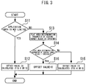
- Fig. 3 is a diagram showing an offset value calculation flow.
- step S11 it is determined whether the application area is limited or not.
- step S12 the evaluation value to which the offset value has been added is used for every block (step S12).
- step S12 the intra-prediction mode offset value used during intra-prediction is calculated using the flow of Fig. 4
- the intra-offset value used during intra/inter determination is calculated using the flow of Fig. 5 .
- the flat area determination parameter of the coding target block is obtained (step S13). It is determined whether the flat area determination parameter of the coding target block is at least the designated threshold or not (step S14). When the flat area determination parameter is lower than the threshold, the evaluation value to which the offset value has been added is used (step S15). In the offset value calculation (step S15), the intra-prediction mode offset value used during intra-prediction is calculated using the flow of Fig. 4 , and the intra-offset value used during intra/inter determination is calculated using the flow of Fig. 5 .
- the pixel values largely vary and are not constant, such as of a black border.
- the flat area determination parameter is at least the threshold, zero is substituted into the offset value, and this function is not applied (step S16).
- this function is not applied (step S16).
- zero is substituted into the offset value according to the flat area determination parameter to limit the application range, thereby preventing the area with nonflat pixel values from being affected.
- Fig. 4 is a diagram showing an intra-prediction mode offset value calculation flow.
- Fig. 5 is a diagram showing an intra-offset value calculation flow.
- the multiple thresholds 1 to n are set, and the offset values different according to the thresholds are set.
- the intra-prediction mode offset value calculation the adjacent block used for intra-prediction is changed. Consequently, the offset value is set with respect to each intra-prediction mode.
- the intra-prediction modes allow prediction in 35 different directions. Prediction based on the block similar to the coding target block reduces the error, thereby improving the encoding efficiency. Specifically, in a motionless area with flat pixel values, such as of a black border, degradation in image quality is subjectively prominent even if the difference of pixel values is small. Thus, the calculated offset value is added to the existing evaluation value, thereby facilitating selection of prediction from the similar block.
- Fig. 6 is a diagram showing an intra-prediction mode determination flow.
- the maximum value is set into the best intra-evaluation value (step S21).
- the loop of the intra-prediction modes (0 to 34) is started (step S22).
- the existing evaluation value is calculated (step S23).
- the existing evaluation value is calculated by the following Math. 3.
- Existing evaluation value D + ⁇ * H
- D indicates the error between the input image and the prediction image
- ⁇ indicates a weighting coefficient
- H indicates header cost required during prediction. It is represented that the lower the evaluation value is, the smaller the amount of data is or the smaller the error from the input image and the better the encoding efficiency the mode has.
- the existing evaluation value represented in Math. 2 is used as it is without reappraisal of this value, and the offset value is added, thereby allowing this embodiment to be easily executed.
- the mode offset value is added to the existing evaluation value to obtain the evaluation value (mode) (step S24).
- Such use of the offset value calculated for every prediction mode allows the appropriate prediction mode to be selected. For example, in a case where the coding target block is in contact with the boundary of the black border at a lower part of the screen in windowboxing video having upper and lower black borders, the larger the flat area determination parameter of the upper adjacent block is, the larger the offset value of the prediction mode in the upward direction is, thereby making the intra-prediction in the upward direction resistant to being selected.
- the prediction is performed on the basis of the black border part. Consequently, the prediction residual becomes small, thereby improving the intra-block image quality.
- the offset is added to the evaluation value so that the precedence can be given to the inter-prediction with respect to the intra-prediction in motionless areas with flat pixel values, such as of black borders.
- the degradation of the reference image used for inter-prediction is low, and the prediction error tends to be low.
- the motion vector is small. Accordingly, the amount of encoding is small. Consequently, it is appropriate to give precedence to the inter-prediction.
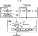
- Fig. 7 is a diagram showing the intra/inter determination flow.
- the existing intra-evaluation value and the existing inter-evaluation value are calculated (steps S31 and S32).
- the intra-evaluation value is obtained by adding the intra-offset value to the existing intra-evaluation value (step S33).
- the best mode is determined to be the intra-mode (step S35).
- the best mode is determined to be the inter-mode (step S36).
- a process of adding the offset value to the existing intra-evaluation value used for intra/inter determination is added.
- the intra/inter determination what has the lower evaluation value is selected.
- the intra-offset value is set to a positive value, the intra-evaluation value becomes large, which makes the intra resistant to being selected.
- the intra-offset value is set to a negative value, the intra tends to be selected.
- setting the intra-offset value to a positive value makes the intra with a large prediction error more resistant to being selected. Selection with the precedence being given to the inter-prediction can improve the image quality.
- the intra-block is selected in the intra/inter determination, improvement in image quality has already been achieved in the intra-prediction.
- Fig. 8 is a diagram showing an example of video (input image).
- Fig. 9 is a diagram showing the frequency distribution of differences from pixel values after encoding with the pixel value of the input image being "a" with respect to a flat part encircled by a rectangle in Fig. 8 .
- the distribution after application has more pixel values close to "a”.
- the image quality where the pixel values after encoding are closer to the pixel values of the input image can be considered as image quality with low degradation. Consequently, application of this embodiment confirms that the image has pixel values close to those of input image and has lower degradation.
Landscapes
- Engineering & Computer Science (AREA)
- Multimedia (AREA)
- Signal Processing (AREA)
- Physics & Mathematics (AREA)
- Discrete Mathematics (AREA)
- General Physics & Mathematics (AREA)
- Compression Or Coding Systems Of Tv Signals (AREA)
Abstract
Description
- The present invention relates to a moving image encoding device that encodes a moving image.
- Intrinsically, encoding is to determine the intra-prediction mode using a local decoded image, and to generate a prediction image using the local decoded image. However, this impairs the advantageous effect of improvement in speed in a case where the speed of the moving image encoding device is intended be improved through parallel processing. Accordingly, intra-prediction mode determination often uses an input image.
- Unfortunately, since final predicted image generation necessarily uses the local decoded image, a possible difference between the input image and the local decoded image causes a problem in that generation of the prediction image from the local decoded image cannot allow the optimal intra-prediction mode to be selected. In particular, in a case where there is a difference between the input image and the local decoded image in an area with flat pixel values, such as a black border of a windowboxed image, an appropriate prediction error cannot be calculated, an intra-prediction mode having a large error is selected, and image degradation becomes visually prominent. Images similar to windowboxed images include a title image which has flat pixel values over the entire image and in which characters are partially written.
- [PTL 1]
JP 2010-283739 A - In
PTL 1, an intra-prediction is performed using an input image. In a case where the difference between the input image and the local decoded image is large, the mode is forcibly changed to a DC mode. Unfortunately, the DC mode creates a prediction image using the average of adjacent pixel data items; although image degradation can be suppressed, the advantageous effect of improving the image quality is insufficient. In case of incapability of calculating the difference between the input image and the local decoded image, the technology ofPTL 1 cannot be adopted. -
PTL 2 describes a method of reducing degradation in image quality during fading. This method switches weighted prediction on and off through control on an area-by-area basis. In the windowboxed area, this prediction is turned off. Unfortunately, the technology ofPTL 2 is inapplicable to normal video without fading. - The present invention has been made to solve the problems described above, and has an object to obtain a moving image encoding device that can improve the image quality of video including a motionless area with flat pixel values, such as in windowboxing.
- A moving image encoding device according to the present invention includes: a computation unit subtracting a prediction image from an input image; an orthogonal transformation unit applying orthogonal transformation to an output of the computation unit; a quantization unit quantizing an output of the orthogonal transformation unit; an encoding unit encoding an output of the quantization unit; and a prediction mode determination unit determining a prediction mode from the input image, wherein the prediction mode is different according to types of an I-picture, a P-picture and a B-picture.
- The present invention makes it possible to improve the image quality of video including a motionless area with flat pixel values, such as in windowboxing.
-
-
Fig. 1 is a diagram showing a moving image encoding device according to an embodiment of present invention. -
Fig. 2 is a diagram showing a processing flow in the prediction mode determination unit. -
Fig. 3 is a diagram showing an offset value calculation flow. -
Fig. 4 is a diagram showing an intra-prediction mode offset value calculation flow. -
Fig. 5 is a diagram showing an intra-offset value calculation flow. -
Fig. 6 is a diagram showing an intra-prediction mode determination flow. -
Fig. 7 is a diagram showing the intra/inter determination flow. -
Fig. 8 is a diagram showing an example of video (input image). -
Fig. 9 is a diagram showing the frequency distribution of differences from pixel values after encoding with the pixel value of the input image being "a" with respect to a flat part encircled by a rectangle inFig. 8 . -
Fig. 1 is a diagram showing a moving image encoding device according to an embodiment of present invention. Acomputation unit 1 subtracts a prediction image from an input image. Anorthogonal transformation unit 2 applies orthogonal transformation, such as discrete cosine transform or Karhunen-Loève transform, to an output of thecomputation unit 1. Note that any method of orthogonal transformation may be adopted. Aquantization unit 3 quantizes the output of theorthogonal transformation unit 2. Any quantization method may be adopted. Anencoding unit 4 encodes the output of thequantization unit 3 and generates a stream output. - An
inverse quantization unit 5 inverse-quantizes the output of thequantization unit 3. Note that any inverse quantization method may be adopted only if the method supports the quantization process in thequantization unit 3. An inverseorthogonal transformation unit 6 applies inverse orthogonal transformation to the output of theinverse quantization unit 5. Note that any inverse orthogonal transformation method may be adopted only if the method supports the orthogonal transformation process in theorthogonal transformation unit 2. Acomputation unit 7 adds the prediction image to the output of theinverse quantization unit 5, and obtains a local reconstructed image. The reconstructed image is subjected to a filter process through adeblocking filter 8 and a SAO (Sample Adaptive Offset) 9, and is subsequently stored in aframe memory 10. - A prediction mode determination unit 11 determines the prediction mode from the input image. The prediction mode is different according to types of an I-picture, a P-picture and a B-picture. More specifically, the I-picture is a picture to be subjected only to intra-prediction. Accordingly, only the intra-prediction is performed to determine the prediction mode. In a case where the P-picture or B-picture, intra-prediction and inter-prediction are performed, and the intra-prediction mode and the inter-prediction mode are determined. Next, intra/inter determination that selects any one of the determined intra-prediction mode and inter-prediction mode to thus determine the prediction mode.
- The intra-prediction mode performs determination through intra-prediction using the pixel values of the image in a surrounding area positioned around a coding target block. The inter-prediction mode performs determination through inter-prediction using the input image and a reference image supplied from the
frame memory 10. - A prediction
image generation unit 12 generates a prediction image using the mode determined by the prediction mode determination unit 11 and the reference image supplied from theframe memory 10. - To obtain the characteristics of an image, such as of windowboxing, the amount of characteristic that can be calculated from information on the input image is used. The amount of characteristic may be information on a pixel value, such as the luminance or chrominance, and can be obtained in the unit of CU (Coding Unit) or picture. In this embodiment, a flat area determination parameter is used to determine a motionless area that has flat pixel values and characterizes windowboxing. Examples of flat area determination parameters include the activity, and the sum of absolute differences between adjacent pixels. The activity is a parameter that represents the degree of distribution of the pixel values of the input image, and is the amount of characteristic that is important in measurement of the complexity of video. The sum of absolute differences between adjacent pixels is a parameter that represents the relationship with adjacent pixels, and is the amount of characteristic for measuring the similarities and differences of the adjacent pixels.
- The activity can be obtained by Math. 1.


- For the I-picture, the offset value is obtained on the basis of the flat area determination parameter, and the intra-prediction is executed on the basis of the evaluation value to which the offset value has been added. For the P-picture and B-picture, the offset value is obtained on the basis of the flat area determination parameter, any one of the intra-prediction mode and the inter-prediction mode is selected on the basis of the evaluation value to which the offset value has been added, and the selected mode is applied to each block of the input image. Such addition of the offset value obtained from the flat area determination parameter to the evaluation value to be used for mode determination can improve the image quality of video that includes a motionless area having flat pixel values, such as of windowboxing.
-
Fig. 2 is a diagram showing a processing flow in the prediction mode determination unit. First, the mode offset value and the intra-offset value are set to zero. Next, it is determined whether the coding target picture is the I-picture or not (step S1). When the coding target picture is the I-picture, the intra-prediction is performed that determines one mode among 35 intra-prediction modes using the intra-prediction mode evaluation value (step S2). The intra-prediction mode evaluation value is a value obtained by adding the intra-prediction mode offset value to an existing evaluation value. The intra-prediction mode offset value is a value determined by the flat area determination parameter. - When the picture is other than the I-picture (P-picture or B-picture), the inter-prediction is performed that detects a motion vector from the reference image and determines the optimal motion vector (step S3). As with the case of I-picture, the intra-prediction is performed (step S4). Thus, the one optimal inter-mode and the one optimal intra-mode are determined.
- Next, the intra/inter determination is performed that determines the best mode from the determined optimal inter-mode using the inter-evaluation value and optimal intra-mode using the intra-evaluation value (step S5). Note that in the present invention, improvement in intra-prediction (steps S2 and S4) and improvement in intra/inter determination (step S5) can be independently configured. More specifically, the case where only the intra-prediction is intended to be enabled can be achieved by not invoking the offset value calculation block in step S5; the case where only the intra/inter determination is intended to be enabled can be achieved by not invoking the offset value calculation blocks in steps S2 and S4.
- The windowboxed area is an area determined to be flat on the basis of the flat area determination parameter. Consequently, it is required that the intra-prediction direction from the block determined to be nonflat should not be selected. The determination of the intra-prediction mode and the intra/inter determination select the mode with the lowest evaluation value. Consequently, increase in the evaluation value can make the mode resistant to being selected. Thus, the evaluation value is calculated on a mode-by-mode basis, and the offset value is added to the evaluation value to correct the evaluation value. The offset value is determined from the magnitude relationship between the flat area determination parameter of the adjacent block to be used for prediction and the set threshold. For example, the offset value is stepwisely changed by setting multiple thresholds and by configuring setting so that the larger the flat area determination parameter of the adjacent block is, the larger the offset is set.
-
Fig. 3 is a diagram showing an offset value calculation flow. First, it is determined whether the application area is limited or not (step S11). In a case where the application area is not specifically limited, the evaluation value to which the offset value has been added is used for every block (step S12). In the offset value calculation (step S12), the intra-prediction mode offset value used during intra-prediction is calculated using the flow ofFig. 4 , and the intra-offset value used during intra/inter determination is calculated using the flow ofFig. 5 . - In a case where the application area is limited, the flat area determination parameter of the coding target block is obtained (step S13). It is determined whether the flat area determination parameter of the coding target block is at least the designated threshold or not (step S14). When the flat area determination parameter is lower than the threshold, the evaluation value to which the offset value has been added is used (step S15). In the offset value calculation (step S15), the intra-prediction mode offset value used during intra-prediction is calculated using the flow of
Fig. 4 , and the intra-offset value used during intra/inter determination is calculated using the flow ofFig. 5 . - In the block where the flat area determination parameter is at least the threshold, the pixel values largely vary and are not constant, such as of a black border. Thus, when the flat area determination parameter is at least the threshold, zero is substituted into the offset value, and this function is not applied (step S16). Typically, since areas with nonflat pixel values are the majority, zero is substituted into the offset value according to the flat area determination parameter to limit the application range, thereby preventing the area with nonflat pixel values from being affected.
-
Fig. 4 is a diagram showing an intra-prediction mode offset value calculation flow.Fig. 5 is a diagram showing an intra-offset value calculation flow. InFigs 4 and5 , themultiple thresholds 1 to n are set, and the offset values different according to the thresholds are set. In the intra-prediction mode offset value calculation, the adjacent block used for intra-prediction is changed. Consequently, the offset value is set with respect to each intra-prediction mode. - The intra-prediction modes allow prediction in 35 different directions. Prediction based on the block similar to the coding target block reduces the error, thereby improving the encoding efficiency. Specifically, in a motionless area with flat pixel values, such as of a black border, degradation in image quality is subjectively prominent even if the difference of pixel values is small. Thus, the calculated offset value is added to the existing evaluation value, thereby facilitating selection of prediction from the similar block.
-
Fig. 6 is a diagram showing an intra-prediction mode determination flow. First, the maximum value is set into the best intra-evaluation value (step S21). Next, the loop of the intra-prediction modes (0 to 34) is started (step S22). Next, the existing evaluation value is calculated (step S23). The existing evaluation value is calculated by the following Math. 3.
- Next, the mode offset value is added to the existing evaluation value to obtain the evaluation value (mode) (step S24). Next, it is determined whether the evaluation value (mode) is lower than the best intra-evaluation value or not (step S25). In the higher case, the best intra mode is not updated, and the next intra-prediction mode is evaluated. On the contrary, in the lower case, the best intra evaluation value is updated to the evaluation value (mode) (step S26), and the next intra-prediction mode is evaluated. After evaluation of all the intra-prediction modes is completed, the loop of the intra-prediction modes (0 to 34) is finished (step S27).
- Such use of the offset value calculated for every prediction mode allows the appropriate prediction mode to be selected. For example, in a case where the coding target block is in contact with the boundary of the black border at a lower part of the screen in windowboxing video having upper and lower black borders, the larger the flat area determination parameter of the upper adjacent block is, the larger the offset value of the prediction mode in the upward direction is, thereby making the intra-prediction in the upward direction resistant to being selected. Thus, in a case where the black border part is encoded, the prediction is performed on the basis of the black border part. Consequently, the prediction residual becomes small, thereby improving the intra-block image quality.
- For the P-picture and B-picture, the offset is added to the evaluation value so that the precedence can be given to the inter-prediction with respect to the intra-prediction in motionless areas with flat pixel values, such as of black borders. Typically, in the flat areas, the degradation of the reference image used for inter-prediction is low, and the prediction error tends to be low. Furthermore, in the inter-prediction in the areas with flat pixel values, the motion vector is small. Accordingly, the amount of encoding is small. Consequently, it is appropriate to give precedence to the inter-prediction.
-
Fig. 7 is a diagram showing the intra/inter determination flow. First, the existing intra-evaluation value and the existing inter-evaluation value are calculated (steps S31 and S32). Next, the intra-evaluation value is obtained by adding the intra-offset value to the existing intra-evaluation value (step S33). Next, it is determined whether the intra-evaluation value is lower than the existing inter-evaluation value or not (step S34). In a case where the intra-evaluation value is lower, the best mode is determined to be the intra-mode (step S35). In the other case, the best mode is determined to be the inter-mode (step S36). Thus, in this embodiment, a process of adding the offset value to the existing intra-evaluation value used for intra/inter determination is added. - In the intra/inter determination, what has the lower evaluation value is selected. When the intra-offset value is set to a positive value, the intra-evaluation value becomes large, which makes the intra resistant to being selected. On the contrary, when the intra-offset value is set to a negative value, the intra tends to be selected. When the block with degraded image quality is the intra, setting the intra-offset value to a positive value makes the intra with a large prediction error more resistant to being selected. Selection with the precedence being given to the inter-prediction can improve the image quality. When the intra-block is selected in the intra/inter determination, improvement in image quality has already been achieved in the intra-prediction.
-
Fig. 8 is a diagram showing an example of video (input image).Fig. 9 is a diagram showing the frequency distribution of differences from pixel values after encoding with the pixel value of the input image being "a" with respect to a flat part encircled by a rectangle inFig. 8 . In comparison between the frequency distributions before and after application of this embodiment, the distribution after application has more pixel values close to "a". Typically, the image quality where the pixel values after encoding are closer to the pixel values of the input image can be considered as image quality with low degradation. Consequently, application of this embodiment confirms that the image has pixel values close to those of input image and has lower degradation. - 1 computation unit, 2 orthogonal transformation unit, 3 quantization unit, 4 encoding unit, 11 prediction mode determination unit
- The preferred aspects of the present disclosure may be summarized as follows:
- [Aspect 1]
A moving image encoding device comprising:- a computation unit subtracting a prediction image from an input image;
- an orthogonal transformation unit applying orthogonal transformation to an output of the computation unit;
- a quantization unit quantizing an output of the orthogonal transformation unit;
- an encoding unit encoding an output of the quantization unit; and
- a prediction mode determination unit performing an intra-prediction to the input image to determine an intra-prediction mode when the input image is an I-picture, and performing the intra-prediction and an inter- prediction to the input image to determine any one of the intra-prediction mode and an inter-prediction mode when the input image is a P-picture and a B-picture,
- wherein the prediction mode determination unit calculates a flat area determination parameter for determining whether each pixel block of the input image is a flat area or not, calculates an offset value based on a threshold determination result of the flat area determination parameter of a block positioned around a coding target block of the input image, and selects and applies a prediction mode of the coding target block based on an evaluation value to which an error between the input image and the prediction image corresponding to the coding target block, header cost integrated with a weighting coefficient, and the offset value are added.
- [Aspect 2]
The moving image encoding device according toaspect 1, wherein the prediction mode determination unit calculates a mode offset value as the offset value, and selects and applies one optimal mode among the intra-prediction modes of the coding target block based on an evaluation value to which the error, the header cost, and the mode offset value are added. - [Aspect 3]
The moving image encoding device according toaspect - [Aspect 4]
The moving image encoding device according toaspect 2, wherein the prediction mode determination unit performs a threshold determination by using multiple thresholds for the flat area determination parameter of the block positioned around the coding target block of the input image, and changes the mode offset value stepwisely so that the larger the flat area determination parameter is, the larger the mode offset value is set. - [Aspect 5]
The moving image encoding device according toaspect 3, wherein the prediction mode determination unit performs a threshold determination by using multiple thresholds for the flat area determination parameter of the block positioned around the coding target block of the input image, and changes the intra-offset value stepwisely so that the larger the flat area determination parameter is, the larger the intra-offset value is set.
Claims (1)
- A moving image encoding device encoding a moving image by using a computation unit subtracting a prediction image from an input image for each pixel block, comprising:a prediction mode determination unit selecting an intra-prediction mode, from the plural intra prediction modes, that generates a prediction image using pixel block adjacent to coding target block,wherein the prediction mode determination unit calculates a flat area determination parameter evaluating a flatness of each pixel block of the input image, calculates for a coding target block an intra prediction mode offset value for each intra prediction mode based on the flat area determination parameter of an adjacent block used for the intra prediction of the coding target block of the input image, calculates an evaluation value evaluating coding cost of the coding target block for each intra prediction mode, and selects the intra prediction modes having a smallest intra evaluation value which is obtained by adding respective intra prediction mode offset values and the corresponding evaluation values.
Applications Claiming Priority (3)
| Application Number | Priority Date | Filing Date | Title |
|---|---|---|---|
| JP2015062905A JP6052319B2 (en) | 2015-03-25 | 2015-03-25 | Video encoding device |
| PCT/JP2016/056641 WO2016152446A1 (en) | 2015-03-25 | 2016-03-03 | Moving image encoding device |
| EP16768349.9A EP3276959B1 (en) | 2015-03-25 | 2016-03-03 | Moving image encoding device |
Related Parent Applications (2)
| Application Number | Title | Priority Date | Filing Date |
|---|---|---|---|
| EP16768349.9A Division-Into EP3276959B1 (en) | 2015-03-25 | 2016-03-03 | Moving image encoding device |
| EP16768349.9A Division EP3276959B1 (en) | 2015-03-25 | 2016-03-03 | Moving image encoding device |
Publications (2)
| Publication Number | Publication Date |
|---|---|
| EP3869799A1 true EP3869799A1 (en) | 2021-08-25 |
| EP3869799B1 EP3869799B1 (en) | 2022-09-14 |
Family
ID=56977877
Family Applications (2)
| Application Number | Title | Priority Date | Filing Date |
|---|---|---|---|
| EP16768349.9A Active EP3276959B1 (en) | 2015-03-25 | 2016-03-03 | Moving image encoding device |
| EP21167177.1A Active EP3869799B1 (en) | 2015-03-25 | 2016-03-03 | Moving image encoding device |
Family Applications Before (1)
| Application Number | Title | Priority Date | Filing Date |
|---|---|---|---|
| EP16768349.9A Active EP3276959B1 (en) | 2015-03-25 | 2016-03-03 | Moving image encoding device |
Country Status (4)
| Country | Link |
|---|---|
| US (2) | US20180020233A1 (en) |
| EP (2) | EP3276959B1 (en) |
| JP (1) | JP6052319B2 (en) |
| WO (1) | WO2016152446A1 (en) |
Families Citing this family (5)
| Publication number | Priority date | Publication date | Assignee | Title |
|---|---|---|---|---|
| JP6272194B2 (en) * | 2014-09-24 | 2018-01-31 | 株式会社日立情報通信エンジニアリング | Moving picture encoding apparatus, moving picture decoding apparatus, and moving picture encoding / decoding method |
| JP6052319B2 (en) * | 2015-03-25 | 2016-12-27 | Nttエレクトロニクス株式会社 | Video encoding device |
| KR20230070062A (en) | 2016-10-04 | 2023-05-19 | 주식회사 비원영상기술연구소 | Image data encoding/decoding method and apparatus |
| US10687054B2 (en) * | 2017-12-20 | 2020-06-16 | Intel Corporation | Decoupled prediction and coding structure for video encoding |
| JP2019201388A (en) * | 2018-05-18 | 2019-11-21 | 富士通株式会社 | Information processing unit, information processing method, and program |
Citations (6)
| Publication number | Priority date | Publication date | Assignee | Title |
|---|---|---|---|---|
| EP2081386A1 (en) * | 2008-01-18 | 2009-07-22 | Panasonic Corporation | High precision edge prediction for intracoding |
| US20090190660A1 (en) * | 2008-01-30 | 2009-07-30 | Toshihiko Kusakabe | Image encoding method |
| JP2010283739A (en) | 2009-06-08 | 2010-12-16 | Mitsubishi Electric Corp | Moving image encoding device |
| US20110007799A1 (en) * | 2009-07-09 | 2011-01-13 | Qualcomm Incorporated | Non-zero rounding and prediction mode selection techniques in video encoding |
| JP2012244353A (en) | 2011-05-18 | 2012-12-10 | Sony Corp | Image processing device and method |
| JP2013138502A (en) * | 2013-03-04 | 2013-07-11 | Canon Inc | Coding apparatus, control method of the same, and computer program |
Family Cites Families (20)
| Publication number | Priority date | Publication date | Assignee | Title |
|---|---|---|---|---|
| WO1999022524A1 (en) * | 1997-10-23 | 1999-05-06 | Mitsubishi Denki Kabushiki Kaisha | Image decoder, image encoder, image communication system, and encoded bit stream converter |
| GB2351916B (en) * | 2000-03-23 | 2001-05-30 | Christopher Howard Field | Putters |
| BRPI0307197B1 (en) * | 2002-11-25 | 2018-06-19 | Godo Kaisha Ip Bridge 1 | MOTION COMPENSATION METHOD, IMAGE CODING METHOD AND IMAGE DECODING METHOD |
| TWI245539B (en) * | 2004-09-22 | 2005-12-11 | Sony Taiwan Ltd | Spatial domain pre-processing to reduce the intra-coding computation complexity |
| JP4877449B2 (en) * | 2004-11-04 | 2012-02-15 | カシオ計算機株式会社 | Moving picture coding apparatus and moving picture coding processing program |
| FR2880745A1 (en) * | 2005-01-07 | 2006-07-14 | France Telecom | VIDEO ENCODING METHOD AND DEVICE |
| CN101370480A (en) * | 2006-02-03 | 2009-02-18 | 赢创罗姆有限责任公司 | Pharmaceutical composition comprising a mixture of a polymer and an active ingredient poorly soluble in water |
| JP2007228519A (en) * | 2006-02-27 | 2007-09-06 | Renesas Technology Corp | Image encoding device and image encoding method |
| KR101370919B1 (en) * | 2006-07-12 | 2014-03-11 | 엘지전자 주식회사 | A method and apparatus for processing a signal |
| US8036270B2 (en) * | 2006-07-27 | 2011-10-11 | Sharp Laboratories Of America, Inc. | Intra-frame flicker reduction in video coding |
| US20100266042A1 (en) * | 2007-03-02 | 2010-10-21 | Han Suh Koo | Method and an apparatus for decoding/encoding a video signal |
| JP2007251996A (en) * | 2007-05-24 | 2007-09-27 | Toshiba Corp | Video coding method and apparatus |
| JP2009111691A (en) * | 2007-10-30 | 2009-05-21 | Hitachi Ltd | Image encoding apparatus, encoding method, image decoding apparatus, and decoding method |
| JP5215951B2 (en) * | 2009-07-01 | 2013-06-19 | キヤノン株式会社 | Encoding apparatus, control method therefor, and computer program |
| GB2491391B (en) * | 2011-06-02 | 2014-09-03 | Canon Kk | Encoding mode values representing prediction modes |
| RU2583040C2 (en) * | 2011-08-30 | 2016-05-10 | Нокиа Текнолоджиз Ой | Device, method and computer program for encoding and decoding video signals |
| WO2014005305A1 (en) * | 2012-07-04 | 2014-01-09 | Intel Corporation | Inter-view filter parameters re-use for three dimensional video coding |
| JP2014082639A (en) * | 2012-10-16 | 2014-05-08 | Canon Inc | Image encoder and method of the same |
| US10212445B2 (en) * | 2014-10-09 | 2019-02-19 | Qualcomm Incorporated | Intra block copy prediction restrictions for parallel processing |
| JP6052319B2 (en) * | 2015-03-25 | 2016-12-27 | Nttエレクトロニクス株式会社 | Video encoding device |
-
2015
- 2015-03-25 JP JP2015062905A patent/JP6052319B2/en active Active
-
2016
- 2016-03-03 EP EP16768349.9A patent/EP3276959B1/en active Active
- 2016-03-03 EP EP21167177.1A patent/EP3869799B1/en active Active
- 2016-03-03 US US15/548,673 patent/US20180020233A1/en not_active Abandoned
- 2016-03-03 WO PCT/JP2016/056641 patent/WO2016152446A1/en not_active Ceased
-
2019
- 2019-06-25 US US16/452,025 patent/US11432005B2/en active Active
Patent Citations (6)
| Publication number | Priority date | Publication date | Assignee | Title |
|---|---|---|---|---|
| EP2081386A1 (en) * | 2008-01-18 | 2009-07-22 | Panasonic Corporation | High precision edge prediction for intracoding |
| US20090190660A1 (en) * | 2008-01-30 | 2009-07-30 | Toshihiko Kusakabe | Image encoding method |
| JP2010283739A (en) | 2009-06-08 | 2010-12-16 | Mitsubishi Electric Corp | Moving image encoding device |
| US20110007799A1 (en) * | 2009-07-09 | 2011-01-13 | Qualcomm Incorporated | Non-zero rounding and prediction mode selection techniques in video encoding |
| JP2012244353A (en) | 2011-05-18 | 2012-12-10 | Sony Corp | Image processing device and method |
| JP2013138502A (en) * | 2013-03-04 | 2013-07-11 | Canon Inc | Coding apparatus, control method of the same, and computer program |
Also Published As
| Publication number | Publication date |
|---|---|
| JP6052319B2 (en) | 2016-12-27 |
| EP3276959A4 (en) | 2018-10-17 |
| EP3276959A1 (en) | 2018-01-31 |
| EP3276959B1 (en) | 2021-05-19 |
| WO2016152446A1 (en) | 2016-09-29 |
| US11432005B2 (en) | 2022-08-30 |
| US20190320201A1 (en) | 2019-10-17 |
| JP2016184801A (en) | 2016-10-20 |
| EP3869799B1 (en) | 2022-09-14 |
| BR112017017282A2 (en) | 2018-04-17 |
| US20180020233A1 (en) | 2018-01-18 |
Similar Documents
| Publication | Publication Date | Title |
|---|---|---|
| US10091500B2 (en) | Video coding method using at least evaluated visual quality and related video coding apparatus | |
| JP5793511B2 (en) | Deblocking filtering control | |
| US11432005B2 (en) | Moving image encoding device | |
| KR101478669B1 (en) | Automatic parameter estimation for adaptive pixel-based filtering | |
| CN102119401B (en) | Method and apparatus for banding artifact detection | |
| JP5553979B2 (en) | Selection of coding tools for video coding based on human visual tolerance | |
| JP4246723B2 (en) | Intraframe predictive coding control method, intraframe predictive coding control apparatus, intraframe predictive coding control program, and computer-readable recording medium storing the program | |
| JP5491506B2 (en) | Method and apparatus for detecting dark noise artifacts | |
| CN114640845A (en) | Encoding and decoding method, device and equipment thereof | |
| JP2006067302A (en) | Image coding apparatus, image coding method, and image coding program | |
| JP2010041191A (en) | Image encoding method and image encoding device | |
| JP4829951B2 (en) | Intraframe predictive coding control method, intraframe predictive coding control apparatus, intraframe predictive coding control program, and computer-readable recording medium storing the program | |
| JP2012175543A (en) | Motion vector detection apparatus, motion vector detection method and moving image encoding device | |
| KR20160061456A (en) | Method and apparatus for fast encoding mode decision based perceptual quality | |
| JP2014017625A (en) | Moving image encoder, control method of the same, and program | |
| JP2008167290A (en) | Transcoder |
Legal Events
| Date | Code | Title | Description |
|---|---|---|---|
| PUAI | Public reference made under article 153(3) epc to a published international application that has entered the european phase |
Free format text: ORIGINAL CODE: 0009012 |
|
| STAA | Information on the status of an ep patent application or granted ep patent |
Free format text: STATUS: REQUEST FOR EXAMINATION WAS MADE |
|
| 17P | Request for examination filed |
Effective date: 20210528 |
|
| AC | Divisional application: reference to earlier application |
Ref document number: 3276959 Country of ref document: EP Kind code of ref document: P |
|
| AK | Designated contracting states |
Kind code of ref document: A1 Designated state(s): AL AT BE BG CH CY CZ DE DK EE ES FI FR GB GR HR HU IE IS IT LI LT LU LV MC MK MT NL NO PL PT RO RS SE SI SK SM TR |
|
| RBV | Designated contracting states (corrected) |
Designated state(s): AL AT BE BG CH CY CZ DE DK EE ES FI FR GB GR HR HU IE IS IT LI LT LU LV MC MK MT NL NO PL PT RO RS SE SI SK SM TR |
|
| GRAP | Despatch of communication of intention to grant a patent |
Free format text: ORIGINAL CODE: EPIDOSNIGR1 |
|
| STAA | Information on the status of an ep patent application or granted ep patent |
Free format text: STATUS: GRANT OF PATENT IS INTENDED |
|
| INTG | Intention to grant announced |
Effective date: 20220406 |
|
| RAP3 | Party data changed (applicant data changed or rights of an application transferred) |
Owner name: NIPPON TELEGRAPH AND TELEPHONE CORPORATION Owner name: NTT ELECTRONICS CORPORATION |
|
| GRAS | Grant fee paid |
Free format text: ORIGINAL CODE: EPIDOSNIGR3 |
|
| GRAA | (expected) grant |
Free format text: ORIGINAL CODE: 0009210 |
|
| STAA | Information on the status of an ep patent application or granted ep patent |
Free format text: STATUS: THE PATENT HAS BEEN GRANTED |
|
| AC | Divisional application: reference to earlier application |
Ref document number: 3276959 Country of ref document: EP Kind code of ref document: P |
|
| AK | Designated contracting states |
Kind code of ref document: B1 Designated state(s): AL AT BE BG CH CY CZ DE DK EE ES FI FR GB GR HR HU IE IS IT LI LT LU LV MC MK MT NL NO PL PT RO RS SE SI SK SM TR |
|
| REG | Reference to a national code |
Ref country code: GB Ref legal event code: FG4D |
|
| REG | Reference to a national code |
Ref country code: CH Ref legal event code: EP |
|
| REG | Reference to a national code |
Ref country code: DE Ref legal event code: R096 Ref document number: 602016075107 Country of ref document: DE |
|
| REG | Reference to a national code |
Ref country code: IE Ref legal event code: FG4D |
|
| REG | Reference to a national code |
Ref country code: AT Ref legal event code: REF Ref document number: 1519418 Country of ref document: AT Kind code of ref document: T Effective date: 20221015 |
|
| REG | Reference to a national code |
Ref country code: LT Ref legal event code: MG9D |
|
| REG | Reference to a national code |
Ref country code: NL Ref legal event code: MP Effective date: 20220914 |
|
| PG25 | Lapsed in a contracting state [announced via postgrant information from national office to epo] |
Ref country code: SE Free format text: LAPSE BECAUSE OF FAILURE TO SUBMIT A TRANSLATION OF THE DESCRIPTION OR TO PAY THE FEE WITHIN THE PRESCRIBED TIME-LIMIT Effective date: 20220914 Ref country code: RS Free format text: LAPSE BECAUSE OF FAILURE TO SUBMIT A TRANSLATION OF THE DESCRIPTION OR TO PAY THE FEE WITHIN THE PRESCRIBED TIME-LIMIT Effective date: 20220914 Ref country code: NO Free format text: LAPSE BECAUSE OF FAILURE TO SUBMIT A TRANSLATION OF THE DESCRIPTION OR TO PAY THE FEE WITHIN THE PRESCRIBED TIME-LIMIT Effective date: 20221214 Ref country code: LV Free format text: LAPSE BECAUSE OF FAILURE TO SUBMIT A TRANSLATION OF THE DESCRIPTION OR TO PAY THE FEE WITHIN THE PRESCRIBED TIME-LIMIT Effective date: 20220914 Ref country code: LT Free format text: LAPSE BECAUSE OF FAILURE TO SUBMIT A TRANSLATION OF THE DESCRIPTION OR TO PAY THE FEE WITHIN THE PRESCRIBED TIME-LIMIT Effective date: 20220914 Ref country code: FI Free format text: LAPSE BECAUSE OF FAILURE TO SUBMIT A TRANSLATION OF THE DESCRIPTION OR TO PAY THE FEE WITHIN THE PRESCRIBED TIME-LIMIT Effective date: 20220914 |
|
| REG | Reference to a national code |
Ref country code: AT Ref legal event code: MK05 Ref document number: 1519418 Country of ref document: AT Kind code of ref document: T Effective date: 20220914 |
|
| PG25 | Lapsed in a contracting state [announced via postgrant information from national office to epo] |
Ref country code: HR Free format text: LAPSE BECAUSE OF FAILURE TO SUBMIT A TRANSLATION OF THE DESCRIPTION OR TO PAY THE FEE WITHIN THE PRESCRIBED TIME-LIMIT Effective date: 20220914 Ref country code: GR Free format text: LAPSE BECAUSE OF FAILURE TO SUBMIT A TRANSLATION OF THE DESCRIPTION OR TO PAY THE FEE WITHIN THE PRESCRIBED TIME-LIMIT Effective date: 20221215 |
|
| PG25 | Lapsed in a contracting state [announced via postgrant information from national office to epo] |
Ref country code: SM Free format text: LAPSE BECAUSE OF FAILURE TO SUBMIT A TRANSLATION OF THE DESCRIPTION OR TO PAY THE FEE WITHIN THE PRESCRIBED TIME-LIMIT Effective date: 20220914 Ref country code: RO Free format text: LAPSE BECAUSE OF FAILURE TO SUBMIT A TRANSLATION OF THE DESCRIPTION OR TO PAY THE FEE WITHIN THE PRESCRIBED TIME-LIMIT Effective date: 20220914 Ref country code: PT Free format text: LAPSE BECAUSE OF FAILURE TO SUBMIT A TRANSLATION OF THE DESCRIPTION OR TO PAY THE FEE WITHIN THE PRESCRIBED TIME-LIMIT Effective date: 20230116 Ref country code: ES Free format text: LAPSE BECAUSE OF FAILURE TO SUBMIT A TRANSLATION OF THE DESCRIPTION OR TO PAY THE FEE WITHIN THE PRESCRIBED TIME-LIMIT Effective date: 20220914 Ref country code: CZ Free format text: LAPSE BECAUSE OF FAILURE TO SUBMIT A TRANSLATION OF THE DESCRIPTION OR TO PAY THE FEE WITHIN THE PRESCRIBED TIME-LIMIT Effective date: 20220914 Ref country code: AT Free format text: LAPSE BECAUSE OF FAILURE TO SUBMIT A TRANSLATION OF THE DESCRIPTION OR TO PAY THE FEE WITHIN THE PRESCRIBED TIME-LIMIT Effective date: 20220914 |
|
| PG25 | Lapsed in a contracting state [announced via postgrant information from national office to epo] |
Ref country code: SK Free format text: LAPSE BECAUSE OF FAILURE TO SUBMIT A TRANSLATION OF THE DESCRIPTION OR TO PAY THE FEE WITHIN THE PRESCRIBED TIME-LIMIT Effective date: 20220914 Ref country code: PL Free format text: LAPSE BECAUSE OF FAILURE TO SUBMIT A TRANSLATION OF THE DESCRIPTION OR TO PAY THE FEE WITHIN THE PRESCRIBED TIME-LIMIT Effective date: 20220914 Ref country code: IS Free format text: LAPSE BECAUSE OF FAILURE TO SUBMIT A TRANSLATION OF THE DESCRIPTION OR TO PAY THE FEE WITHIN THE PRESCRIBED TIME-LIMIT Effective date: 20230114 Ref country code: EE Free format text: LAPSE BECAUSE OF FAILURE TO SUBMIT A TRANSLATION OF THE DESCRIPTION OR TO PAY THE FEE WITHIN THE PRESCRIBED TIME-LIMIT Effective date: 20220914 |
|
| REG | Reference to a national code |
Ref country code: DE Ref legal event code: R097 Ref document number: 602016075107 Country of ref document: DE |
|
| PG25 | Lapsed in a contracting state [announced via postgrant information from national office to epo] |
Ref country code: NL Free format text: LAPSE BECAUSE OF FAILURE TO SUBMIT A TRANSLATION OF THE DESCRIPTION OR TO PAY THE FEE WITHIN THE PRESCRIBED TIME-LIMIT Effective date: 20220914 Ref country code: AL Free format text: LAPSE BECAUSE OF FAILURE TO SUBMIT A TRANSLATION OF THE DESCRIPTION OR TO PAY THE FEE WITHIN THE PRESCRIBED TIME-LIMIT Effective date: 20220914 |
|
| PLBE | No opposition filed within time limit |
Free format text: ORIGINAL CODE: 0009261 |
|
| STAA | Information on the status of an ep patent application or granted ep patent |
Free format text: STATUS: NO OPPOSITION FILED WITHIN TIME LIMIT |
|
| PG25 | Lapsed in a contracting state [announced via postgrant information from national office to epo] |
Ref country code: DK Free format text: LAPSE BECAUSE OF FAILURE TO SUBMIT A TRANSLATION OF THE DESCRIPTION OR TO PAY THE FEE WITHIN THE PRESCRIBED TIME-LIMIT Effective date: 20220914 |
|
| 26N | No opposition filed |
Effective date: 20230615 |
|
| PG25 | Lapsed in a contracting state [announced via postgrant information from national office to epo] |
Ref country code: SI Free format text: LAPSE BECAUSE OF FAILURE TO SUBMIT A TRANSLATION OF THE DESCRIPTION OR TO PAY THE FEE WITHIN THE PRESCRIBED TIME-LIMIT Effective date: 20220914 |
|
| PG25 | Lapsed in a contracting state [announced via postgrant information from national office to epo] |
Ref country code: MC Free format text: LAPSE BECAUSE OF FAILURE TO SUBMIT A TRANSLATION OF THE DESCRIPTION OR TO PAY THE FEE WITHIN THE PRESCRIBED TIME-LIMIT Effective date: 20220914 |
|
| REG | Reference to a national code |
Ref country code: BE Ref legal event code: MM Effective date: 20230331 |
|
| PG25 | Lapsed in a contracting state [announced via postgrant information from national office to epo] |
Ref country code: LU Free format text: LAPSE BECAUSE OF NON-PAYMENT OF DUE FEES Effective date: 20230303 |
|
| REG | Reference to a national code |
Ref country code: IE Ref legal event code: MM4A |
|
| PG25 | Lapsed in a contracting state [announced via postgrant information from national office to epo] |
Ref country code: IE Free format text: LAPSE BECAUSE OF NON-PAYMENT OF DUE FEES Effective date: 20230303 |
|
| PG25 | Lapsed in a contracting state [announced via postgrant information from national office to epo] |
Ref country code: BE Free format text: LAPSE BECAUSE OF NON-PAYMENT OF DUE FEES Effective date: 20230331 |
|
| PG25 | Lapsed in a contracting state [announced via postgrant information from national office to epo] |
Ref country code: IT Free format text: LAPSE BECAUSE OF FAILURE TO SUBMIT A TRANSLATION OF THE DESCRIPTION OR TO PAY THE FEE WITHIN THE PRESCRIBED TIME-LIMIT Effective date: 20220914 |
|
| PG25 | Lapsed in a contracting state [announced via postgrant information from national office to epo] |
Ref country code: BG Free format text: LAPSE BECAUSE OF FAILURE TO SUBMIT A TRANSLATION OF THE DESCRIPTION OR TO PAY THE FEE WITHIN THE PRESCRIBED TIME-LIMIT Effective date: 20220914 |
|
| PG25 | Lapsed in a contracting state [announced via postgrant information from national office to epo] |
Ref country code: BG Free format text: LAPSE BECAUSE OF FAILURE TO SUBMIT A TRANSLATION OF THE DESCRIPTION OR TO PAY THE FEE WITHIN THE PRESCRIBED TIME-LIMIT Effective date: 20220914 |
|
| PGFP | Annual fee paid to national office [announced via postgrant information from national office to epo] |
Ref country code: CH Payment date: 20250401 Year of fee payment: 10 |
|
| PG25 | Lapsed in a contracting state [announced via postgrant information from national office to epo] |
Ref country code: CY Free format text: LAPSE BECAUSE OF FAILURE TO SUBMIT A TRANSLATION OF THE DESCRIPTION OR TO PAY THE FEE WITHIN THE PRESCRIBED TIME-LIMIT; INVALID AB INITIO Effective date: 20160303 |
|
| PG25 | Lapsed in a contracting state [announced via postgrant information from national office to epo] |
Ref country code: HU Free format text: LAPSE BECAUSE OF FAILURE TO SUBMIT A TRANSLATION OF THE DESCRIPTION OR TO PAY THE FEE WITHIN THE PRESCRIBED TIME-LIMIT; INVALID AB INITIO Effective date: 20160303 |
|
| PG25 | Lapsed in a contracting state [announced via postgrant information from national office to epo] |
Ref country code: TR Free format text: LAPSE BECAUSE OF FAILURE TO SUBMIT A TRANSLATION OF THE DESCRIPTION OR TO PAY THE FEE WITHIN THE PRESCRIBED TIME-LIMIT Effective date: 20220914 |
|
| REG | Reference to a national code |
Ref country code: CH Ref legal event code: R18 Free format text: ST27 STATUS EVENT CODE: U-0-0-R10-R18 (AS PROVIDED BY THE NATIONAL OFFICE) Effective date: 20260127 |
|
| REG | Reference to a national code |
Ref country code: DE Ref legal event code: R081 Ref document number: 602016075107 Country of ref document: DE Owner name: NTT, INC., JP Free format text: FORMER OWNERS: NIPPON TELEGRAPH AND TELEPHONE CORPORATION, TOKYO, JP; NTT ELECTRONICS CORPORATION, YOKOHAMA-SHI, KANAGAWA, JP Ref country code: DE Ref legal event code: R081 Ref document number: 602016075107 Country of ref document: DE Owner name: NTT ELECTRONICS CORPORATION, YOKOHAMA-SHI, JP Free format text: FORMER OWNERS: NIPPON TELEGRAPH AND TELEPHONE CORPORATION, TOKYO, JP; NTT ELECTRONICS CORPORATION, YOKOHAMA-SHI, KANAGAWA, JP Ref country code: DE Ref legal event code: R082 Ref document number: 602016075107 Country of ref document: DE Representative=s name: DENNEMEYER & ASSOCIATES RECHTSANWALTSGESELLSCH, DE |
|
| REG | Reference to a national code |
Ref country code: CH Ref legal event code: U11 Free format text: ST27 STATUS EVENT CODE: U-0-0-U10-U11 (AS PROVIDED BY THE NATIONAL OFFICE) Effective date: 20260401 |
|
| PGFP | Annual fee paid to national office [announced via postgrant information from national office to epo] |
Ref country code: GB Payment date: 20260202 Year of fee payment: 11 |
|
| PGFP | Annual fee paid to national office [announced via postgrant information from national office to epo] |
Ref country code: DE Payment date: 20260128 Year of fee payment: 11 |
|
| PGFP | Annual fee paid to national office [announced via postgrant information from national office to epo] |
Ref country code: FR Payment date: 20260209 Year of fee payment: 11 |