EP3869253B1 - Connection structure and optical cable connection box - Google Patents
Connection structure and optical cable connection box Download PDFInfo
- Publication number
- EP3869253B1 EP3869253B1 EP21151492.2A EP21151492A EP3869253B1 EP 3869253 B1 EP3869253 B1 EP 3869253B1 EP 21151492 A EP21151492 A EP 21151492A EP 3869253 B1 EP3869253 B1 EP 3869253B1
- Authority
- EP
- European Patent Office
- Prior art keywords
- connection structure
- path
- fiber
- disposed
- optical
- Prior art date
- Legal status (The legal status is an assumption and is not a legal conclusion. Google has not performed a legal analysis and makes no representation as to the accuracy of the status listed.)
- Active
Links
Images



Classifications
-
- G—PHYSICS
- G02—OPTICS
- G02B—OPTICAL ELEMENTS, SYSTEMS OR APPARATUS
- G02B6/00—Light guides; Structural details of arrangements comprising light guides and other optical elements, e.g. couplings
- G02B6/44—Mechanical structures for providing tensile strength and external protection for fibres, e.g. optical transmission cables
- G02B6/4439—Auxiliary devices
- G02B6/444—Systems or boxes with surplus lengths
- G02B6/4453—Cassettes
- G02B6/4454—Cassettes with splices
-
- G—PHYSICS
- G02—OPTICS
- G02B—OPTICAL ELEMENTS, SYSTEMS OR APPARATUS
- G02B6/00—Light guides; Structural details of arrangements comprising light guides and other optical elements, e.g. couplings
- G02B6/44—Mechanical structures for providing tensile strength and external protection for fibres, e.g. optical transmission cables
- G02B6/4439—Auxiliary devices
- G02B6/444—Systems or boxes with surplus lengths
- G02B6/4441—Boxes
- G02B6/4446—Cable boxes, e.g. splicing boxes with two or more multi fibre cables
Definitions
- This application relates to the field of communications technologies, and in particular, to a connection structure.
- An optical cable connection box mainly implements a protection function on optical cables on an optical fiber network after the optical cables are connected to each other.
- cables with different lengths need to be provided according to distances to users.
- CORNING cable lengths on an existing network are serialized in specifications: 33/55/105/160/350.
- a site engineer usually selects a longer optical cable after estimation, causing redundancy for optical fibers of the optical cable.
- One type of optical cable connection box can provide adapter connection but does not support optical fiber splicing and storage, causing use inconvenience.
- Another type of optical cable connection box is provided with a splicing tray, and supports optical fiber splicing and storage in the splicing tray.
- the optical cable connection box with the splicing tray has a relatively large volume.
- US 5 838 871 A describes an optical fiber cable connection organizer device that includes a support assembly with lateral accessways for the fibers of the cables, an arrangement for holding splices between the fibers and an arrangement for stowing a surplus length of the jointed fibers. It further includes two sets of magazines for stowing additional slack in the fibers from the two cables.
- Embodiments of this application provide a connection structure and an optical cable connection box, to reduce a volume and also implement storage of redundant optical fibers.
- the invention is defined by the appended claims. Embodiments and examples not covered by the claims are meant to illustrate, and facilitate the understanding of, the claimed invention.
- a connection structure including a splicing region and a fiber management region that are disposed with a distance therebetween along a circumferential direction of the connection structure.
- the connection structure is a cylinder-like object and the circumferential direction is a direction circling a central axis of the connection structure, wherein the splicing region is usable to splice optical fibers in different optical cables by using a splicing device to implement connection between the different optical cables and wherein the fiber management region is configured to store redundant optical fibers of optical cables,
- a fiber routing path passing through the connection structure in the splicing region and the connection structure in the fiber management region is further disposed in the connection structure, so that an optical fiber extends into the fiber management region for storage through the fiber routing path from the splicing region.
- connection structure includes the splicing region and the fiber management region that are disposed with a distance therebetween along the circumferential direction of the connection structure.
- the splicing region and the fiber management region are located on different planes. Because optical fiber splicing and storage do not need to be performed in a same region in the connection structure, space of the connection structure can be effectively used. In this way, the connection structure has a compact structure, thereby reducing a volume of the connection structure.
- optical fiber splicing and optical fiber storage are separated in the connection structure according to functional regions, which facilitates work of an operator, thereby improving optical cable connection efficiency.
- the fiber routing path is disposed in a groove on an outer sidewall of the connection structure, to facilitate extension of the optical fiber from the splicing region to the fiber management region and also protect the optical fiber.
- a first positioning plate and a second positioning plate protrude from a sidewall of the fiber routing path.
- the first positioning plate and the second positioning plate are disposed opposite each other.
- a groove is formed between the first positioning plate and the second positioning plate.
- the first positioning plate and the second positioning plate are configured to: prevent the optical fiber from coming out of the fiber routing path and protect the optical fiber.
- the groove is configured to facilitate the optical fiber to enter the fiber routing path.
- a depression is further disposed in the splicing region on the connection structure.
- the depression includes two sidewalls and a bottom wall. The bottom wall is connected between the two sidewalls.
- a cable leading-in path is further disposed in the connection structure. The cable leading-in path passes through the sidewalls of the depression.
- the fiber routing path passes through the bottom wall of the depression, to facilitate the optical fiber in an optical cable passing through the cable leading-in path to enter the fiber routing path.
- the cable leading-in path is located at an end of the connection structure, and the cable leading-in path is coaxially disposed with the connection structure.
- a central axis of the optical cable passing through the cable leading-in path, a central axis of the cable leading-in path, and a central axis of the connection structure can be overlapped, thereby improving transmission quality of an optical signal.
- connection structure further includes a cabling path.
- the cabling path is disposed in a groove on the bottom wall of the depression close to the cable leading-in path.
- the cabling path is connected to the fiber routing path.
- a cabling path disposed in a clearance mode is used between the fiber routing path and the cable leading-in path, so that smooth cabling is implemented on the optical fiber, thereby reducing a risk of a sudden change to an optical signal.
- the sidewall includes a cushion surface.
- the cushion surface is an arc surface protruding to an interior of the depression, and is used to cushion a bending angle of the optical fiber to prevent the sudden change to the optical signal.
- a stop portion protrudes from a sidewall of the cable leading-in path close to the depression, and is configured to abut against the optical cable, to avoid forward movement of the optical cable, thereby improving connection reliability of the optical cable in the connection structure.
- the connection structure includes an inner support container and a clamping apparatus.
- the splicing region, the fiber management region, the cable leading-in path, and the fiber routing path are all disposed on the inner support container.
- the clamping apparatus protrudes from the bottom wall of the depression.
- a clamping groove is disposed in the clamping apparatus to clamp a splicing protection sleeve sleeved on the optical fiber.
- the clamping apparatus includes two elastic arms.
- the two elastic arms are disposed with a distance therebetween to form the clamping groove.
- the elastic arms can elastically clamp the splicing protection sleeve sleeved on the optical fiber, thereby improving clamping reliability of the clamping apparatus.
- connection structure further includes a compression apparatus.
- An accommodating portion is disposed in a groove on the sidewall of the cable leading-in path.
- the stop portion is located between the accommodating portion and the depression.
- the compression apparatus is accommodated in the accommodating portion and fixed on the sidewall of the cable leading-in path.
- the compression apparatus is configured to compress the optical cable passing through the cable leading-in path.
- the compression apparatus includes a compression block and an adjustment component.
- An adjustment hole is disposed through the compression block.
- the compression block is accommodated in the accommodating portion and is fixed on the sidewall of the cable leading-in path.
- the adjustment component passes through the adjustment hole in an adjustable manner.
- One end of the adjustment component away from the compression block is configured to compress the optical cable passing through the cable leading-in path.
- the adjustment component may adjust, by using the adjustment hole in the compression block, a tightening degree of abutting the optical cable, to accommodate optical cables with different shapes, for example, round or flat cables.
- a clamping jaw is further disposed at an end of the inner support container along a circumferential direction of the inner support container, and the connection structure further includes a fastener.
- the fastener passes through the end of the inner support container.
- the clamping jaw clamps the fastener.
- the fastener is provided with a guide path.
- the guide path is coaxially disposed with and connected to the cable leading-in path in the inner support container. The fastener is fixed through clamping by using the clamping jaw, to facilitate assembly and disassembly of the optical cable.
- connection structure further includes a sealing kit.
- the sealing kit is sleeved on the end of the inner support container in a sealing manner, and is configured to connect, in a sealing manner, to an inner wall of a protection sleeve sleeved on the inner support container, to implement sealing and prevent entrance of water vapor, dust, and the like.
- a boss is disposed in the fiber management region of the connection structure, and is configured to wind the optical fiber to implement optical fiber storage.
- an optical cable connection box including the foregoing connection structure and a protection sleeve.
- the protection sleeve is sleeved on the connection structure.
- the fiber routing path passing through the connection structure in the splicing region and the connection structure in the fiber management region is disposed in the connection structure, so that a redundant optical fiber can be transferred from the original splicing region to the fiber management region for storage.
- space of the connection structure can be effectively used, thereby reducing space occupied by the connection structure.
- the protection sleeve is sleeved on the connection structure, thereby reducing space occupied by the optical cable connection box.
- the protection sleeve includes a first protection sleeve and a second protection sleeve.
- the first protection sleeve is sleeved on one end of the connection structure
- the second protection sleeve is sleeved on the other end of the connection structure and is screwed to the first protection sleeve, which facilitates disassembly and assembly of the optical cable connection box.
- an axial direction means a direction along a rotating central axis of a cylinder-like object, that is, a direction the same as the central axis; and a circumferential direction means a direction circling a central axis.
- an optical cable connection box 100 includes a connection structure 10 and a protection sleeve 30 sleeved on the connection structure 10, to implement a protection function on different optical cables (201 and 203 shown in FIG. 4 to FIG. 6 ) after being connected to each other.
- the optical cable connection box 100 is configured to implement connection between single-core optical cables.
- the protection sleeve 30 includes a first protection sleeve 31 and a second protection sleeve 33.
- the first protection sleeve 31 is sleeved on one end of the connection structure 10, and the second protection sleeve 33 is sleeved on the other end of the connection structure 10 and is screwed to the first protection sleeve 33, which facilitates disassembly and assembly of the optical cable connection box 100. Because the first protection sleeve 31 and the second protection sleeve 33 are a sleeve structure instead of a conventional flip structure, space occupied by the optical cable connection box 100 is reduced.
- first protection sleeve 31 and the second protection sleeve 33 are not limited to be screwed to each other, and the first protection sleeve 31 and the second protection sleeve 33 may also be connected in another manner, for example, through clamping.
- a structure of the protection sleeve 30 is not limited.
- the protection sleeve 30 may alternatively be an entire sleeve.
- the connection structure 10 includes a splicing region 101 and a fiber management region 103 that are disposed with a distance therebetween along a circumferential direction of the connection structure 10.
- the splicing region 101 and the fiber management region 103 are located on different planes.
- the splicing region 101 is used to splice optical fibers in different optical cables by using a splicing device, to implement connection between the different optical cables.
- the fiber management region 103 is used to store redundant optical fibers of the optical cables.
- a side that is of the connection structure 10 and on which the splicing region 101 is disposed is referred to as a front side
- a side that is of the connection structure 10 and on which the fiber management region 103 is disposed is referred to as a back side.
- the splicing region 101 is disposed on the front side of the connection structure 10
- the fiber management region 103 is disposed on the back side of the connection structure 10. It may be understood that, it is not limited that the splicing region 101 is disposed on the front side of the connection structure 10, and it is not limited that the fiber management region 103 is disposed on the back side of the connection structure 10.
- the splicing region 101 and the fiber management region 103 only need to be located on different planes.
- connection structure 10 further includes a fiber routing path 104 passing through the connection structure 10 in the splicing region 101 and the connection structure 10 in the fiber management region 103, so that an optical fiber can extend into the fiber management region 103 for storage through the fiber routing path 104 from the splicing region 101.
- the splicing region 101 and the fiber management region 103 are disposed with a distance therebetween along a circumferential direction of the connection structure 10. In this way, the splicing region 101 and the fiber management region 103 are located on different planes, so that optical fiber splicing and storage are not performed in a same region. Therefore, space of the connection structure 10 can be effectively used, and the connection structure 10 has a compact structure, thereby reducing a volume of the connection structure 10.
- optical fiber splicing and optical fiber storage are separated in the connection structure 10 according to functional regions, which facilitates work of an operator, thereby improving optical cable connection efficiency.
- the fiber routing path 104 is disposed in a groove on an outer sidewall of the connection structure 10, to facilitate extension of the optical fiber.
- a first positioning plate 1041 and a second positioning plate 1043 protrude from a sidewall of the fiber routing path 104.
- the first positioning plate 1041 and the second positioning plate 1043 are disposed opposite each other, to prevent the optical fiber from coming out of the fiber routing path 104 and protect the optical fiber.
- a groove 1045 is formed between the first positioning plate 1041 and the second positioning plate 1043, to facilitate the optical fiber to enter the fiber routing path 104.
- a depression 105 is disposed in the splicing region 101 of the connection structure 10.
- the depression 105 includes a bottom wall 1051 and two sidewalls 1053.
- the bottom wall 1051 is connected between the two sidewalls 1053.
- a cable leading-in path 106 is further disposed in the connection structure 10.
- the cable leading-in path 106 passes through the sidewalls of the depression 105.
- the cable leading-in path 106 is located at an end of the connection structure 10.
- the cable leading-in path 106 is coaxially disposed with the connection structure 10, to dispose the optical cable.
- the cable leading-in path 106 is coaxially disposed with the connection structure 10.
- a central axis of the cable leading-in path 106 overlaps a central axis of the connection structure 10.
- a central axis of the optical cable passing through the cable leading-in path 106, the central axis of the cable leading-in path 106, and the central axis of the connection structure 10 can be overlapped, thereby improving transmission quality of an optical signal.
- the connection structure 10 further includes a cabling path 108.
- the cabling path 108 is disposed in a groove on the bottom wall of the depression 105 close to the cable leading-in path 106.
- the cabling path 108 is connected to the fiber routing path 104. In this way, smooth cabling is implemented on the optical fiber, and a risk that the optical fiber is broken due to bending is reduced, thereby reducing a risk of a sudden change to an optical signal transmitted over the optical fiber.
- a stop portion 1069 protrudes from a sidewall of the cable leading-in path 106 close to the depression 105, and is used to abut against the optical cable. For connection, an outer layer of the optical cable is partially stripped to expose the optical fiber. In this way, a stripping stop portion is formed on the optical cable.
- the stop portion 1069 is configured to abut against the stripping stop portion of the optical cable, to avoid forward movement of the optical cable, thereby improving connection reliability of the optical cable.
- a boss 1091 is disposed in the fiber management region 103 of the connection structure 10, and is configured to wind the optical fiber to implement optical fiber storage.
- connection structure 10 includes an inner support container 11, a clamping apparatus 12, a fastener 13, a sealing kit 15, and a compression apparatus 19.
- the splicing region 101, the fiber management region 103, the fiber routing path 104, and the cable leading-in path 106 are all disposed on the inner support container 11.
- the inner support container 11 is approximately a cylinder-like structure.
- a central axis of the inner support container 11 is the central axis of the connection structure 10.
- the clamping apparatus 12 is disposed on the bottom wall 1051 of the depression 105.
- a clamping groove 121 (shown in FIG. 4 ) is disposed in the clamping apparatus 12 to clamp a splicing protection sleeve sleeved on the optical fiber.
- the clamping apparatus 12 is an elastic apparatus.
- Each clamping apparatus 12 includes two elastic arms 123.
- the two elastic arms 123 are disposed with a distance therebetween to form the clamping groove 121, to elastically clamp the splicing protection sleeve sleeved on the optical fiber.
- the two clamping apparatuses 12 are disposed with a distance therebetween to form a splicing card connector region 1011, to facilitate optical fiber splicing.
- the clamping groove 121 is disposed along an axial direction of the connection structure 10. It may be understood that a structure of the clamping apparatus 12 and a quantity of clamping apparatuses 12 are not limited, and the clamping apparatus 12 may be another elastic structure provided that the clamping apparatus 12 can clamp the splicing protection sleeve sleeved on the optical fiber. It may be understood that there may alternatively be more than two elastic arms 123 provided that the elastic arms 123 can clamp the splicing protection sleeve.
- a plurality of clamping jaws 115 are further disposed at an end of the inner support container 11 along a circumferential direction of the inner support container 11.
- the fastener 13 fixedly passes through the end of the inner support container 11.
- the clamping jaws 115 clamp the fastener 13.
- the fastener 13 is provided with a guide path 131 (shown in FIG. 7 ).
- the guide path 131 is coaxially disposed with and connected to the cable leading-in path 106.
- the guide path 131 is used to fasten the optical cable.
- An accommodating portion 1060 (shown in FIG. 7 ) is disposed in a groove on the sidewall of the cable leading-in path 106.
- the stop portion 1069 is located between the accommodating portion 1061 and the depression 105.
- the compression apparatus 19 is accommodated in the accommodating portion 1060 and fixed on the sidewall of the cable leading-in path 106.
- the compression apparatus 19 is configured to abut the optical cable passing through the cable leading-in path 106 to compress the optical cable, thereby improving stability of the optical cable fastened to the inner support container 11.
- the compression apparatus 19 includes a compression block 191 and an adjustment component 193.
- the compression block 191 is accommodated in the accommodating portion 1060.
- An adjustment hole 1911 is disposed through the compression block 191.
- the adjustment component 193 passes through the adjustment hole 1911 of the compression block 191.
- One end of the adjustment component 193 away from the compression block 191 is configured to abut the optical cable to compress the optical cable, thereby improving stability of the optical cable fastened to the inner support container 11.
- the adjustment component 193 may adjust, by using the compression block 191 and the accommodating portion 1060, a tightening degree of abutting the optical cable, to accommodate optical cables with different shapes, for example, round or flat cables.
- the adjustment hole 1911 is a threaded hole, and the adjustment component 193 is a threaded component.
- the adjustment hole 1911 is a threaded hole
- the adjustment component 193 is a threaded component, provided that the adjustment component 193 can adjust, by using the adjustment hole 1911, the tightening degree of abutting the optical cable.
- the four fiber routing paths 104 are approximately disposed in four corners of the bottom wall 1051 of the depression 105. It may be understood that a quantity of fiber routing paths 104 is not limited. For example, the quantity of fiber routing paths 104 may alternatively be one, two, three, or five.
- a first optical cable 201 fixedly passes through the cable leading-in path 106 at an end of the connection structure 10, an optical fiber exposed when an outer layer of the first optical cable 201 is removed enters the splicing region 101 through the cable leading-in path 106, extends to the depression 105 through the cabling path 108, and enters the fiber management region 103 through the fiber routing path 104 for storage.
- a second optical cable 203 fixedly passes through the cable leading-in path 106 at the other end of the connection structure 10, an optical fiber exposed when an outer layer of the second optical cable 203 is removed enters the splicing region 101 through the the cable leading-in path 106, extends to the depression 105 through the the cabling path 108, and enters the fiber management region 103 through the fiber routing path 104 for storage.
- optical fiber directions of the optical fibers of the first optical cable 201 and the second optical cable 203 are guided to an axial direction through the fiber routing path 104 and the cabling path 108, that is, an optical cable leading-in direction.
- the optical fibers of the first optical cable 201 and the second optical cable 203 are connected by using the splicing protection sleeve.
- the optical fiber of the first optical cable and the optical fiber of the second optical cable are spliced by using a splicing device, so that the first optical cable 201 and the second optical cable 203 are connected and enter the clamping groove.
- optical cable connection box 100 may be alternatively configured to implement connection between multi-core optical cables.
- connection structure 10 may be an integrated structure.
- connection structure 50 is provided being roughly the same as the connection structure illustrated in FIG. 1, FIG. 2 , and FIG. 3 .
- the connection structure 50 includes a splicing region 501 and a fiber management region 503 that are disposed with a distance therebetween along a circumferential direction of the connection structure 50.
- a fiber routing path 504 passes through the connection structure 50 in the splicing region 501 and the connection structure 50 in the fiber management region 503.
- a depression 505 is disposed in the splicing region 501 on the connection structure 50.
- a cable leading-in path 506 passing through sidewalls of the depression 505 is disposed on the connection structure 50.
- a difference between the two connection structures is that a clamping apparatus 52 is a boss structure disposed on a bottom wall of the depression 505, and a clamping groove 512 is disposed on the clamping apparatus 52.
- a sidewall 5053 of the depression 505 includes a cushion surface 5055.
- the cushion surface 5055 is an arc surface protruding to an interior of the depression 505, and is used to cushion a bending angle of the optical fiber to prevent a sudden change to an optical signal.
Landscapes
- Physics & Mathematics (AREA)
- General Physics & Mathematics (AREA)
- Optics & Photonics (AREA)
- Light Guides In General And Applications Therefor (AREA)
- Mechanical Coupling Of Light Guides (AREA)
Description
- This application relates to the field of communications technologies, and in particular, to a connection structure.
- An optical cable connection box mainly implements a protection function on optical cables on an optical fiber network after the optical cables are connected to each other. Currently, when a prefabricated optical cable is deployed in the home, cables with different lengths need to be provided according to distances to users. For example, CORNING cable lengths on an existing network are serialized in specifications: 33/55/105/160/350. In actual application, a site engineer usually selects a longer optical cable after estimation, causing redundancy for optical fibers of the optical cable. One type of optical cable connection box can provide adapter connection but does not support optical fiber splicing and storage, causing use inconvenience. Another type of optical cable connection box is provided with a splicing tray, and supports optical fiber splicing and storage in the splicing tray. However, the optical cable connection box with the splicing tray has a relatively large volume.
-
US 5 838 871 A describes an optical fiber cable connection organizer device that includes a support assembly with lateral accessways for the fibers of the cables, an arrangement for holding splices between the fibers and an arrangement for stowing a surplus length of the jointed fibers. It further includes two sets of magazines for stowing additional slack in the fibers from the two cables. - Embodiments of this application provide a connection structure and an optical cable connection box, to reduce a volume and also implement storage of redundant optical fibers. The invention is defined by the appended claims. Embodiments and examples not covered by the claims are meant to illustrate, and facilitate the understanding of, the claimed invention.
- According to a first aspect according to claim 1, a connection structure is provided, including a splicing region and a fiber management region that are disposed with a distance therebetween along a circumferential direction of the connection structure. The connection structure is a cylinder-like object and the circumferential direction is a direction circling a central axis of the connection structure, wherein the splicing region is usable to splice optical fibers in different optical cables by using a splicing device to implement connection between the different optical cables and wherein the fiber management region is configured to store redundant optical fibers of optical cables, A fiber routing path passing through the connection structure in the splicing region and the connection structure in the fiber management region is further disposed in the connection structure, so that an optical fiber extends into the fiber management region for storage through the fiber routing path from the splicing region.
- The connection structure includes the splicing region and the fiber management region that are disposed with a distance therebetween along the circumferential direction of the connection structure. In other words, the splicing region and the fiber management region are located on different planes. Because optical fiber splicing and storage do not need to be performed in a same region in the connection structure, space of the connection structure can be effectively used. In this way, the connection structure has a compact structure, thereby reducing a volume of the connection structure. In addition, optical fiber splicing and optical fiber storage are separated in the connection structure according to functional regions, which facilitates work of an operator, thereby improving optical cable connection efficiency.
- According to the first aspect, the fiber routing path is disposed in a groove on an outer sidewall of the connection structure, to facilitate extension of the optical fiber from the splicing region to the fiber management region and also protect the optical fiber.
- According to the first aspect, a first positioning plate and a second positioning plate protrude from a sidewall of the fiber routing path. The first positioning plate and the second positioning plate are disposed opposite each other. A groove is formed between the first positioning plate and the second positioning plate. The first positioning plate and the second positioning plate are configured to: prevent the optical fiber from coming out of the fiber routing path and protect the optical fiber. The groove is configured to facilitate the optical fiber to enter the fiber routing path.
- With reference to the first aspect, in a first possible implementation of the first aspect, a depression is further disposed in the splicing region on the connection structure. The depression includes two sidewalls and a bottom wall. The bottom wall is connected between the two sidewalls. A cable leading-in path is further disposed in the connection structure. The cable leading-in path passes through the sidewalls of the depression. The fiber routing path passes through the bottom wall of the depression, to facilitate the optical fiber in an optical cable passing through the cable leading-in path to enter the fiber routing path.
- With reference to the first aspect or the first possible implementation of the first aspect, in a second possible implementation of the first aspect, the cable leading-in path is located at an end of the connection structure, and the cable leading-in path is coaxially disposed with the connection structure. In this way, a central axis of the optical cable passing through the cable leading-in path, a central axis of the cable leading-in path, and a central axis of the connection structure can be overlapped, thereby improving transmission quality of an optical signal.
- With reference to the first aspect or the first to the second possible implementations of the first aspect, in a third possible implementation of the first aspect, the connection structure further includes a cabling path. The cabling path is disposed in a groove on the bottom wall of the depression close to the cable leading-in path. The cabling path is connected to the fiber routing path. A cabling path disposed in a clearance mode is used between the fiber routing path and the cable leading-in path, so that smooth cabling is implemented on the optical fiber, thereby reducing a risk of a sudden change to an optical signal.
- With reference to the first aspect or the first to the third possible implementations of the first aspect, in a fourth possible implementation of the first aspect, the sidewall includes a cushion surface. The cushion surface is an arc surface protruding to an interior of the depression, and is used to cushion a bending angle of the optical fiber to prevent the sudden change to the optical signal.
- With reference to the first aspect or the first to the fourth possible implementations of the first aspect, in a fifth possible implementation of the first aspect, a stop portion protrudes from a sidewall of the cable leading-in path close to the depression, and is configured to abut against the optical cable, to avoid forward movement of the optical cable, thereby improving connection reliability of the optical cable in the connection structure.
- With reference to the first aspect or the first to the fifth possible implementations of the first aspect, in an sixth possible implementation of the first aspect, the connection structure includes an inner support container and a clamping apparatus. The splicing region, the fiber management region, the cable leading-in path, and the fiber routing path are all disposed on the inner support container. The clamping apparatus protrudes from the bottom wall of the depression. A clamping groove is disposed in the clamping apparatus to clamp a splicing protection sleeve sleeved on the optical fiber.
- With reference to the first aspect or the first to the sixth possible implementations of the first aspect, in a seventh possible implementation of the first aspect, the clamping apparatus includes two elastic arms. The two elastic arms are disposed with a distance therebetween to form the clamping groove. The elastic arms can elastically clamp the splicing protection sleeve sleeved on the optical fiber, thereby improving clamping reliability of the clamping apparatus.
- With reference to the first aspect or the first to the seventh possible implementations of the first aspect, in an eighth possible implementation of the first aspect, the connection structure further includes a compression apparatus. An accommodating portion is disposed in a groove on the sidewall of the cable leading-in path. The stop portion is located between the accommodating portion and the depression. The compression apparatus is accommodated in the accommodating portion and fixed on the sidewall of the cable leading-in path. The compression apparatus is configured to compress the optical cable passing through the cable leading-in path.
- With reference to the first aspect or the first to the eighth possible implementations of the first aspect, in an ninth possible implementation of the first aspect, the compression apparatus includes a compression block and an adjustment component. An adjustment hole is disposed through the compression block. The compression block is accommodated in the accommodating portion and is fixed on the sidewall of the cable leading-in path. The adjustment component passes through the adjustment hole in an adjustable manner. One end of the adjustment component away from the compression block is configured to compress the optical cable passing through the cable leading-in path. The adjustment component may adjust, by using the adjustment hole in the compression block, a tightening degree of abutting the optical cable, to accommodate optical cables with different shapes, for example, round or flat cables.
- With reference to the first aspect or the first to the ninth possible implementations of the first aspect, in a tenth possible implementation of the first aspect, a clamping jaw is further disposed at an end of the inner support container along a circumferential direction of the inner support container, and the connection structure further includes a fastener. The fastener passes through the end of the inner support container. The clamping jaw clamps the fastener. The fastener is provided with a guide path. The guide path is coaxially disposed with and connected to the cable leading-in path in the inner support container. The fastener is fixed through clamping by using the clamping jaw, to facilitate assembly and disassembly of the optical cable.
- With reference to the first aspect or the first to the tenth possible implementations of the first aspect, in a eleventh possible implementation of the first aspect, the connection structure further includes a sealing kit. The sealing kit is sleeved on the end of the inner support container in a sealing manner, and is configured to connect, in a sealing manner, to an inner wall of a protection sleeve sleeved on the inner support container, to implement sealing and prevent entrance of water vapor, dust, and the like.
- With reference to the first aspect or the first to the eleventh possible implementations of the first aspect, in a twelfth possible implementation of the first aspect, a boss is disposed in the fiber management region of the connection structure, and is configured to wind the optical fiber to implement optical fiber storage.
- In some examples, an optical cable connection box is provided, including the foregoing connection structure and a protection sleeve. The protection sleeve is sleeved on the connection structure.
- According to the optical cable connection box provided in this application, the fiber routing path passing through the connection structure in the splicing region and the connection structure in the fiber management region is disposed in the connection structure, so that a redundant optical fiber can be transferred from the original splicing region to the fiber management region for storage. In this way, space of the connection structure can be effectively used, thereby reducing space occupied by the connection structure. In addition, instead of a flip structure, the protection sleeve is sleeved on the connection structure, thereby reducing space occupied by the optical cable connection box.
- In some examples, the protection sleeve includes a first protection sleeve and a second protection sleeve. The first protection sleeve is sleeved on one end of the connection structure, and the second protection sleeve is sleeved on the other end of the connection structure and is screwed to the first protection sleeve, which facilitates disassembly and assembly of the optical cable connection box.
-
-
FIG. 1 is a schematic stereoscopic assembly diagram of an optical cable connection box; -
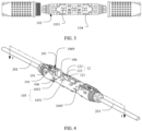
FIG. 2 is a schematic diagram from another angle of view of the optical cable connection box shown inFIG. 1 ; -
FIG. 3 is a schematic stereoscopic exploded view of the optical cable connection box shown inFIG. 1 ; -
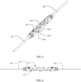
FIG. 4 is a schematic stereoscopic diagram of a connection structure of an optical cable connection box; -
FIG. 5 is a schematic diagram from another angle of view of the connection structure shown inFIG. 4 ; -
FIG. 6 is a cutaway diagram along a line I-I of the connection structure shown inFIG. 4 ; -
FIG. 7 is a locally enlarged schematic diagram of the connection structure shown inFIG. 6 ; -
FIG. 8 is a schematic stereoscopic diagram of a connection structure; -
FIG. 9 is a locally enlarged schematic diagram of the connection structure shown inFIG. 8 ; and -
FIG. 10 is a cutaway diagram along a line II-II of the connection structure shown inFIG. 8 . - Generally, an axial direction means a direction along a rotating central axis of a cylinder-like object, that is, a direction the same as the central axis; and a circumferential direction means a direction circling a central axis.
- Referring to
FIG. 1, FIG. 2 , andFIG. 3 , an opticalcable connection box 100 includes aconnection structure 10 and aprotection sleeve 30 sleeved on theconnection structure 10, to implement a protection function on different optical cables (201 and 203 shown inFIG. 4 to FIG. 6 ) after being connected to each other. The opticalcable connection box 100 is configured to implement connection between single-core optical cables. Theprotection sleeve 30 includes afirst protection sleeve 31 and asecond protection sleeve 33. Thefirst protection sleeve 31 is sleeved on one end of theconnection structure 10, and thesecond protection sleeve 33 is sleeved on the other end of theconnection structure 10 and is screwed to thefirst protection sleeve 33, which facilitates disassembly and assembly of the opticalcable connection box 100. Because thefirst protection sleeve 31 and thesecond protection sleeve 33 are a sleeve structure instead of a conventional flip structure, space occupied by the opticalcable connection box 100 is reduced. It may be understood that thefirst protection sleeve 31 and thesecond protection sleeve 33 are not limited to be screwed to each other, and thefirst protection sleeve 31 and thesecond protection sleeve 33 may also be connected in another manner, for example, through clamping. A structure of theprotection sleeve 30 is not limited. For example, theprotection sleeve 30 may alternatively be an entire sleeve. - Referring to
FIG. 4 andFIG. 5 , theconnection structure 10 includes asplicing region 101 and afiber management region 103 that are disposed with a distance therebetween along a circumferential direction of theconnection structure 10. In other words, thesplicing region 101 and thefiber management region 103 are located on different planes. Thesplicing region 101 is used to splice optical fibers in different optical cables by using a splicing device, to implement connection between the different optical cables. Thefiber management region 103 is used to store redundant optical fibers of the optical cables. A side that is of theconnection structure 10 and on which thesplicing region 101 is disposed is referred to as a front side, and a side that is of theconnection structure 10 and on which thefiber management region 103 is disposed is referred to as a back side. In other words, thesplicing region 101 is disposed on the front side of theconnection structure 10, and thefiber management region 103 is disposed on the back side of theconnection structure 10. It may be understood that, it is not limited that thesplicing region 101 is disposed on the front side of theconnection structure 10, and it is not limited that thefiber management region 103 is disposed on the back side of theconnection structure 10. Thesplicing region 101 and thefiber management region 103 only need to be located on different planes. - The
connection structure 10 further includes afiber routing path 104 passing through theconnection structure 10 in thesplicing region 101 and theconnection structure 10 in thefiber management region 103, so that an optical fiber can extend into thefiber management region 103 for storage through thefiber routing path 104 from thesplicing region 101. Thesplicing region 101 and thefiber management region 103 are disposed with a distance therebetween along a circumferential direction of theconnection structure 10. In this way, thesplicing region 101 and thefiber management region 103 are located on different planes, so that optical fiber splicing and storage are not performed in a same region. Therefore, space of theconnection structure 10 can be effectively used, and theconnection structure 10 has a compact structure, thereby reducing a volume of theconnection structure 10. In addition, optical fiber splicing and optical fiber storage are separated in theconnection structure 10 according to functional regions, which facilitates work of an operator, thereby improving optical cable connection efficiency. - The
fiber routing path 104 is disposed in a groove on an outer sidewall of theconnection structure 10, to facilitate extension of the optical fiber. Afirst positioning plate 1041 and asecond positioning plate 1043 protrude from a sidewall of thefiber routing path 104. Thefirst positioning plate 1041 and thesecond positioning plate 1043 are disposed opposite each other, to prevent the optical fiber from coming out of thefiber routing path 104 and protect the optical fiber. Agroove 1045 is formed between thefirst positioning plate 1041 and thesecond positioning plate 1043, to facilitate the optical fiber to enter thefiber routing path 104. - Referring to
FIG. 4 again, adepression 105 is disposed in thesplicing region 101 of theconnection structure 10. Thedepression 105 includes abottom wall 1051 and two sidewalls 1053. Thebottom wall 1051 is connected between the two sidewalls 1053. A cable leading-inpath 106 is further disposed in theconnection structure 10. The cable leading-inpath 106 passes through the sidewalls of thedepression 105. The cable leading-inpath 106 is located at an end of theconnection structure 10. The cable leading-inpath 106 is coaxially disposed with theconnection structure 10, to dispose the optical cable. The cable leading-inpath 106 is coaxially disposed with theconnection structure 10. In other words, a central axis of the cable leading-inpath 106 overlaps a central axis of theconnection structure 10. In this way, a central axis of the optical cable passing through the cable leading-inpath 106, the central axis of the cable leading-inpath 106, and the central axis of theconnection structure 10 can be overlapped, thereby improving transmission quality of an optical signal. - The
connection structure 10 further includes acabling path 108. Thecabling path 108 is disposed in a groove on the bottom wall of thedepression 105 close to the cable leading-inpath 106. Thecabling path 108 is connected to thefiber routing path 104. In this way, smooth cabling is implemented on the optical fiber, and a risk that the optical fiber is broken due to bending is reduced, thereby reducing a risk of a sudden change to an optical signal transmitted over the optical fiber. - A
stop portion 1069 protrudes from a sidewall of the cable leading-inpath 106 close to thedepression 105, and is used to abut against the optical cable. For connection, an outer layer of the optical cable is partially stripped to expose the optical fiber. In this way, a stripping stop portion is formed on the optical cable. Thestop portion 1069 is configured to abut against the stripping stop portion of the optical cable, to avoid forward movement of the optical cable, thereby improving connection reliability of the optical cable. - Referring to
FIG. 5 again, aboss 1091 is disposed in thefiber management region 103 of theconnection structure 10, and is configured to wind the optical fiber to implement optical fiber storage. - More specifically, referring to
FIG. 2 again, theconnection structure 10 includes aninner support container 11, a clampingapparatus 12, afastener 13, a sealingkit 15, and acompression apparatus 19. - The
splicing region 101, thefiber management region 103, thefiber routing path 104, and the cable leading-inpath 106 are all disposed on theinner support container 11. Theinner support container 11 is approximately a cylinder-like structure. A central axis of theinner support container 11 is the central axis of theconnection structure 10. - The clamping
apparatus 12 is disposed on thebottom wall 1051 of thedepression 105. A clamping groove 121 (shown inFIG. 4 ) is disposed in theclamping apparatus 12 to clamp a splicing protection sleeve sleeved on the optical fiber. The clampingapparatus 12 is an elastic apparatus. Each clampingapparatus 12 includes twoelastic arms 123. The twoelastic arms 123 are disposed with a distance therebetween to form the clampinggroove 121, to elastically clamp the splicing protection sleeve sleeved on the optical fiber. There are two clampingapparatuses 12. The twoclamping apparatuses 12 are disposed with a distance therebetween to form a splicingcard connector region 1011, to facilitate optical fiber splicing. The clampinggroove 121 is disposed along an axial direction of theconnection structure 10. It may be understood that a structure of the clampingapparatus 12 and a quantity of clampingapparatuses 12 are not limited, and theclamping apparatus 12 may be another elastic structure provided that the clampingapparatus 12 can clamp the splicing protection sleeve sleeved on the optical fiber. It may be understood that there may alternatively be more than twoelastic arms 123 provided that theelastic arms 123 can clamp the splicing protection sleeve. - A plurality of clamping jaws 115 (shown in
FIG. 2 ) are further disposed at an end of theinner support container 11 along a circumferential direction of theinner support container 11. Thefastener 13 fixedly passes through the end of theinner support container 11. The clampingjaws 115 clamp thefastener 13. Thefastener 13 is provided with a guide path 131 (shown inFIG. 7 ). Theguide path 131 is coaxially disposed with and connected to the cable leading-inpath 106. Theguide path 131 is used to fasten the optical cable. - An accommodating portion 1060 (shown in
FIG. 7 ) is disposed in a groove on the sidewall of the cable leading-inpath 106. Thestop portion 1069 is located between the accommodating portion 1061 and thedepression 105. Thecompression apparatus 19 is accommodated in theaccommodating portion 1060 and fixed on the sidewall of the cable leading-inpath 106. Thecompression apparatus 19 is configured to abut the optical cable passing through the cable leading-inpath 106 to compress the optical cable, thereby improving stability of the optical cable fastened to theinner support container 11. - The
compression apparatus 19 includes acompression block 191 and anadjustment component 193. Thecompression block 191 is accommodated in theaccommodating portion 1060. Anadjustment hole 1911 is disposed through thecompression block 191. Theadjustment component 193 passes through theadjustment hole 1911 of thecompression block 191. One end of theadjustment component 193 away from thecompression block 191 is configured to abut the optical cable to compress the optical cable, thereby improving stability of the optical cable fastened to theinner support container 11. Theadjustment component 193 may adjust, by using thecompression block 191 and theaccommodating portion 1060, a tightening degree of abutting the optical cable, to accommodate optical cables with different shapes, for example, round or flat cables. Theadjustment hole 1911 is a threaded hole, and theadjustment component 193 is a threaded component. It may be understood that, it is not limited that theadjustment hole 1911 is a threaded hole, and it is not limited that theadjustment component 193 is a threaded component, provided that theadjustment component 193 can adjust, by using theadjustment hole 1911, the tightening degree of abutting the optical cable. - There are four
fiber routing paths 104. The fourfiber routing paths 104 are approximately disposed in four corners of thebottom wall 1051 of thedepression 105. It may be understood that a quantity offiber routing paths 104 is not limited. For example, the quantity offiber routing paths 104 may alternatively be one, two, three, or five. - In an application scenario, a first
optical cable 201 fixedly passes through the cable leading-inpath 106 at an end of theconnection structure 10, an optical fiber exposed when an outer layer of the firstoptical cable 201 is removed enters thesplicing region 101 through the cable leading-inpath 106, extends to thedepression 105 through thecabling path 108, and enters thefiber management region 103 through thefiber routing path 104 for storage. Similarly, a secondoptical cable 203 fixedly passes through the cable leading-inpath 106 at the other end of theconnection structure 10, an optical fiber exposed when an outer layer of the secondoptical cable 203 is removed enters thesplicing region 101 through the the cable leading-inpath 106, extends to thedepression 105 through the thecabling path 108, and enters thefiber management region 103 through thefiber routing path 104 for storage. After fiber management is completed, optical fiber directions of the optical fibers of the firstoptical cable 201 and the secondoptical cable 203 are guided to an axial direction through thefiber routing path 104 and thecabling path 108, that is, an optical cable leading-in direction. The optical fibers of the firstoptical cable 201 and the secondoptical cable 203 are connected by using the splicing protection sleeve. In addition, the optical fiber of the first optical cable and the optical fiber of the second optical cable are spliced by using a splicing device, so that the firstoptical cable 201 and the secondoptical cable 203 are connected and enter the clamping groove. - It may be understood that the optical
cable connection box 100 may be alternatively configured to implement connection between multi-core optical cables. - It may be understood that the
connection structure 10 may be an integrated structure. - Referring to
FIG. 8 ,FIG. 9, and FIG. 10 , aconnection structure 50 is provided being roughly the same as the connection structure illustrated inFIG. 1, FIG. 2 , andFIG. 3 . For example, theconnection structure 50 includes asplicing region 501 and afiber management region 503 that are disposed with a distance therebetween along a circumferential direction of theconnection structure 50. Afiber routing path 504 passes through theconnection structure 50 in thesplicing region 501 and theconnection structure 50 in thefiber management region 503. Adepression 505 is disposed in thesplicing region 501 on theconnection structure 50. A cable leading-inpath 506 passing through sidewalls of thedepression 505 is disposed on theconnection structure 50. A difference between the two connection structures is that aclamping apparatus 52 is a boss structure disposed on a bottom wall of thedepression 505, and a clamping groove 512 is disposed on theclamping apparatus 52. A sidewall 5053 of thedepression 505 includes acushion surface 5055. Thecushion surface 5055 is an arc surface protruding to an interior of thedepression 505, and is used to cushion a bending angle of the optical fiber to prevent a sudden change to an optical signal. - The foregoing descriptions are not intended to limit the protection scope of this application. The scope of protection is defined by the appended claims.
Claims (13)
- A connection structure (10), comprising a splicing region (101) and a fiber management region (103) that are disposed with a distance therebetween along a circumferential direction of the connection structure, wherein the connection structure is a cylinder-like object and the circumferential direction is a direction circling a central axis of the connection structure, wherein the splicing region is usable to splice optical fibers in different optical cables by using a splicing device to implement connection between the different optical cables and wherein the fiber management region is configured to store redundant optical fibers of the optical cables, wherein a fiber routing path (104) passing through the connection structure in the splicing region and the connection structure in the fiber management region is further disposed in the connection structure, so that an optical fiber extends into the fiber management region for storage through the fiber routing path from the splicing region, and wherein the fiber routing path is disposed in a groove on an outer sidewall of the connection structure,
characterized in that
a first positioning plate (1041) and a second positioning plate (1043) protrude from a sidewall of the fiber routing path, the first positioning plate and the second positioning plate are disposed opposite each other, to prevent the optical fiber from coming out of the fiber routing path (104) and protect the optical fiber, and an entering groove (1045) is formed between the first positioning plate and the second positioning plate, in order to facilitate the optical fiber to enter the fiber routing path (104). - The connection structure according claim 1, wherein a depression (105) is further disposed in the splicing region on the connection structure, the depression comprises two depression sidewalls (1053) and one bottom wall (1051), the bottom wall is connected between the two depression sidewalls, a cable leading-in path (106) is further disposed in the connection structure such that an optical cable fixedly passes through the cable leading-in path at an end of the connection structure, the cable leading-in path passes through the depression sidewalls, and the fiber routing path passes through the bottom wall of the depression.
- The connection structure according to claim 2, wherein the cable leading-in path is located at the end of the connection structure, and the cable leading-in path is coaxially disposed with the connection structure.
- The connection structure according to claim 3, wherein the connection structure further comprises a cabling path (108), the cabling path is disposed in a groove on the bottom wall of the depression close to the cable leading-in path, and the cabling path is connected to the fiber routing path, such that the optical fiber exposed when an outer layer of the optical cable is removed enters the splicing region through the cable leading-in path, extends to the depression through the cabling path, and enters the fiber management region through the fiber routing path for storage.
- The connection structure according to claim 2, wherein at least one of the two depression sidewalls (1053) comprises a cushion surface (5055), and the cushion surface is an arc surface protruding to an interior of the depression.
- The connection structure according to claim 2, wherein a stop portion (1069) protrudes from a sidewall of the cable leading-in path close to the depression, and is configured to abut against the optical cable.
- The connection structure according to claim 2, wherein the connection structure comprises an inner support container (11) and a clamping apparatus (12), the splicing region, the fiber management region, the cable leading-in path, and the fiber routing path are all disposed on the inner support container, the clamping apparatus protrudes from the bottom wall of the depression, and a clamping groove is disposed in the clamping apparatus to clamp a splicing protection sleeve sleeved on the optical fiber.
- The connection structure according to claim 7, wherein the clamping apparatus comprises two elastic arms (123), and the two elastic arms are disposed with a distance therebetween to form the clamping groove.
- The connection structure according to claim 7, wherein the connection structure further comprises a compression apparatus, an accommodating portion is disposed in a groove on a sidewall of the cable leading-in path, the stop portion is located between the accommodating portion and the depression, the compression apparatus is accommodated in the accommodating portion and fixed on the sidewall of the cable leading-in path, and the compression apparatus is configured to compress the optical cable passing through the cable leading-in path.
- The connection structure according to claim 9, wherein the compression apparatus comprises a compression block (191) and an adjustment component (193), an adjustment hole (1911) is disposed through the compression block, the compression block is accommodated in the accommodating portion and is fixed on the sidewall of the cable leading-in path, the adjustment component passes through the adjustment hole in an adjustable manner, and one end of the adjustment component away from the compression block is configured to compress the optical cable passing through the cable leading-in path.
- The connection structure according to claim 7, wherein a clamping jaw (115) is further disposed at an end of the inner support container along a circumferential direction of the inner support container, the connection structure further comprises a fastener, the fastener passes through the end of the inner support container, the clamping jaw clamps the fastener, the fastener is provided with a guide path, and the guide path is coaxially disposed with and connected to the cable leading-in path in the inner support container, wherein the guide path is used to fasten the optical cable.
- The connection structure according to claim 11, wherein the connection structure further comprises a sealing kit, and the sealing kit is sleeved on the end of the inner support container in a sealing manner and is disposed close to the clamping jaw, and is configured to connect, in a sealing manner, to an inner wall of a protection sleeve sleeved on the inner support container.
- The connection structure according to claim 7, wherein a boss (1091) is disposed in the fiber management region of the connection structure, and is configured to wind the optical fiber to implement optical fiber storage.
Applications Claiming Priority (1)
| Application Number | Priority Date | Filing Date | Title |
|---|---|---|---|
| CN202020191330.4U CN212160169U (en) | 2020-02-20 | 2020-02-20 | Connection structure and optical cable connection box |
Publications (2)
| Publication Number | Publication Date |
|---|---|
| EP3869253A1 EP3869253A1 (en) | 2021-08-25 |
| EP3869253B1 true EP3869253B1 (en) | 2025-05-21 |
Family
ID=73712960
Family Applications (1)
| Application Number | Title | Priority Date | Filing Date |
|---|---|---|---|
| EP21151492.2A Active EP3869253B1 (en) | 2020-02-20 | 2021-01-14 | Connection structure and optical cable connection box |
Country Status (2)
| Country | Link |
|---|---|
| EP (1) | EP3869253B1 (en) |
| CN (1) | CN212160169U (en) |
Families Citing this family (1)
| Publication number | Priority date | Publication date | Assignee | Title |
|---|---|---|---|---|
| CN115201981A (en) * | 2022-06-15 | 2022-10-18 | 国网河北省电力有限公司经济技术研究院 | Connecting protection device for power communication optical cable |
Family Cites Families (5)
| Publication number | Priority date | Publication date | Assignee | Title |
|---|---|---|---|---|
| US4428645A (en) * | 1981-01-28 | 1984-01-31 | Gk Technologies, Incorporated | Cable accumulator |
| JPH0746163B2 (en) * | 1986-12-05 | 1995-05-17 | 古河電気工業株式会社 | Optical cable connection part of power / optical composite cable |
| FR2733843B1 (en) * | 1995-05-03 | 1997-05-30 | Alcatel Submarcom | ORGANIZER DEVICE FOR CONNECTING FIBER OPTIC CABLES AND JUNCTION BOX FOR OPTICAL CABLES |
| US6094518A (en) * | 1998-10-30 | 2000-07-25 | A.T.&T. Corp. | Fiber optic cable restoration enclosure |
| GB0710990D0 (en) * | 2007-06-08 | 2007-07-18 | Tyco Electronics Raychem Nv | Splice closure and fibre organiser device |
-
2020
- 2020-02-20 CN CN202020191330.4U patent/CN212160169U/en active Active
-
2021
- 2021-01-14 EP EP21151492.2A patent/EP3869253B1/en active Active
Also Published As
| Publication number | Publication date |
|---|---|
| CN212160169U (en) | 2020-12-15 |
| EP3869253A1 (en) | 2021-08-25 |
Similar Documents
| Publication | Publication Date | Title |
|---|---|---|
| AU2021201049B2 (en) | Cable distribution system | |
| CN113261215B (en) | Cable terminal assembly with anti-drop structure | |
| US6461055B1 (en) | Fiber optic adapter with attenuator and method | |
| US7512304B2 (en) | Drop terminal with anchor block for retaining a stub cable | |
| US8254741B2 (en) | Optical cable connecting closure and optical interconnection system | |
| US20160103290A1 (en) | Distribution cable with bidirectional breakout locations | |
| TW201028752A (en) | Telecommunications outlet box | |
| JP2008514988A (en) | Connector and splice holder device | |
| US20190025516A1 (en) | Optical fiber inline splice assemblies | |
| EP3869253A1 (en) | Connection structure and optical cable connection box | |
| US20090264021A1 (en) | Connection device | |
| KR200294692Y1 (en) | Optical termination panel | |
| KR20170002976A (en) | Fiber optic splice closure | |
| JP2000039537A (en) | adapter | |
| KR101237516B1 (en) | Ribbon unite | |
| JP2020134742A (en) | Light termination box | |
| US11215779B2 (en) | Fiber optic management device | |
| CN101646964A (en) | Optical wiring system | |
| JP3955804B2 (en) | Optical cable connection closure | |
| KR20240116697A (en) | Junction box for underground optical cable branch with removable fixing member | |
| WO2022192670A1 (en) | Components for fiber optic systems | |
| JP2002221638A (en) | Optical splitter | |
| CN121091453A (en) | Protection device for laying indoor wiring optical cable corner | |
| JP3181286U (en) | Optical termination box | |
| JP2007057806A (en) | WDM filter holder in optical fiber housing of optical receiver |
Legal Events
| Date | Code | Title | Description |
|---|---|---|---|
| PUAI | Public reference made under article 153(3) epc to a published international application that has entered the european phase |
Free format text: ORIGINAL CODE: 0009012 |
|
| STAA | Information on the status of an ep patent application or granted ep patent |
Free format text: STATUS: REQUEST FOR EXAMINATION WAS MADE |
|
| 17P | Request for examination filed |
Effective date: 20210114 |
|
| AK | Designated contracting states |
Kind code of ref document: A1 Designated state(s): AL AT BE BG CH CY CZ DE DK EE ES FI FR GB GR HR HU IE IS IT LI LT LU LV MC MK MT NL NO PL PT RO RS SE SI SK SM TR |
|
| STAA | Information on the status of an ep patent application or granted ep patent |
Free format text: STATUS: EXAMINATION IS IN PROGRESS |
|
| 17Q | First examination report despatched |
Effective date: 20220607 |
|
| GRAP | Despatch of communication of intention to grant a patent |
Free format text: ORIGINAL CODE: EPIDOSNIGR1 |
|
| STAA | Information on the status of an ep patent application or granted ep patent |
Free format text: STATUS: GRANT OF PATENT IS INTENDED |
|
| INTG | Intention to grant announced |
Effective date: 20250110 |
|
| GRAS | Grant fee paid |
Free format text: ORIGINAL CODE: EPIDOSNIGR3 |
|
| GRAA | (expected) grant |
Free format text: ORIGINAL CODE: 0009210 |
|
| STAA | Information on the status of an ep patent application or granted ep patent |
Free format text: STATUS: THE PATENT HAS BEEN GRANTED |
|
| AK | Designated contracting states |
Kind code of ref document: B1 Designated state(s): AL AT BE BG CH CY CZ DE DK EE ES FI FR GB GR HR HU IE IS IT LI LT LU LV MC MK MT NL NO PL PT RO RS SE SI SK SM TR |
|
| REG | Reference to a national code |
Ref country code: GB Ref legal event code: FG4D |
|
| REG | Reference to a national code |
Ref country code: CH Ref legal event code: EP |
|
| REG | Reference to a national code |
Ref country code: DE Ref legal event code: R096 Ref document number: 602021030989 Country of ref document: DE |
|
| REG | Reference to a national code |
Ref country code: IE Ref legal event code: FG4D |
|
| REG | Reference to a national code |
Ref country code: NL Ref legal event code: MP Effective date: 20250521 |
|
| PG25 | Lapsed in a contracting state [announced via postgrant information from national office to epo] |
Ref country code: PT Free format text: LAPSE BECAUSE OF FAILURE TO SUBMIT A TRANSLATION OF THE DESCRIPTION OR TO PAY THE FEE WITHIN THE PRESCRIBED TIME-LIMIT Effective date: 20250922 Ref country code: FI Free format text: LAPSE BECAUSE OF FAILURE TO SUBMIT A TRANSLATION OF THE DESCRIPTION OR TO PAY THE FEE WITHIN THE PRESCRIBED TIME-LIMIT Effective date: 20250521 Ref country code: ES Free format text: LAPSE BECAUSE OF FAILURE TO SUBMIT A TRANSLATION OF THE DESCRIPTION OR TO PAY THE FEE WITHIN THE PRESCRIBED TIME-LIMIT Effective date: 20250521 |
|
| REG | Reference to a national code |
Ref country code: LT Ref legal event code: MG9D |
|
| PG25 | Lapsed in a contracting state [announced via postgrant information from national office to epo] |
Ref country code: GR Free format text: LAPSE BECAUSE OF FAILURE TO SUBMIT A TRANSLATION OF THE DESCRIPTION OR TO PAY THE FEE WITHIN THE PRESCRIBED TIME-LIMIT Effective date: 20250822 Ref country code: NO Free format text: LAPSE BECAUSE OF FAILURE TO SUBMIT A TRANSLATION OF THE DESCRIPTION OR TO PAY THE FEE WITHIN THE PRESCRIBED TIME-LIMIT Effective date: 20250821 |
|
| PG25 | Lapsed in a contracting state [announced via postgrant information from national office to epo] |
Ref country code: PL Free format text: LAPSE BECAUSE OF FAILURE TO SUBMIT A TRANSLATION OF THE DESCRIPTION OR TO PAY THE FEE WITHIN THE PRESCRIBED TIME-LIMIT Effective date: 20250521 Ref country code: NL Free format text: LAPSE BECAUSE OF FAILURE TO SUBMIT A TRANSLATION OF THE DESCRIPTION OR TO PAY THE FEE WITHIN THE PRESCRIBED TIME-LIMIT Effective date: 20250521 |
|
| PG25 | Lapsed in a contracting state [announced via postgrant information from national office to epo] |
Ref country code: BG Free format text: LAPSE BECAUSE OF FAILURE TO SUBMIT A TRANSLATION OF THE DESCRIPTION OR TO PAY THE FEE WITHIN THE PRESCRIBED TIME-LIMIT Effective date: 20250521 |
|
| PG25 | Lapsed in a contracting state [announced via postgrant information from national office to epo] |
Ref country code: HR Free format text: LAPSE BECAUSE OF FAILURE TO SUBMIT A TRANSLATION OF THE DESCRIPTION OR TO PAY THE FEE WITHIN THE PRESCRIBED TIME-LIMIT Effective date: 20250521 |
|
| PG25 | Lapsed in a contracting state [announced via postgrant information from national office to epo] |
Ref country code: RS Free format text: LAPSE BECAUSE OF FAILURE TO SUBMIT A TRANSLATION OF THE DESCRIPTION OR TO PAY THE FEE WITHIN THE PRESCRIBED TIME-LIMIT Effective date: 20250821 |
|
| PG25 | Lapsed in a contracting state [announced via postgrant information from national office to epo] |
Ref country code: IS Free format text: LAPSE BECAUSE OF FAILURE TO SUBMIT A TRANSLATION OF THE DESCRIPTION OR TO PAY THE FEE WITHIN THE PRESCRIBED TIME-LIMIT Effective date: 20250921 |
|
| PG25 | Lapsed in a contracting state [announced via postgrant information from national office to epo] |
Ref country code: LV Free format text: LAPSE BECAUSE OF FAILURE TO SUBMIT A TRANSLATION OF THE DESCRIPTION OR TO PAY THE FEE WITHIN THE PRESCRIBED TIME-LIMIT Effective date: 20250521 |
|
| REG | Reference to a national code |
Ref country code: AT Ref legal event code: MK05 Ref document number: 1797215 Country of ref document: AT Kind code of ref document: T Effective date: 20250521 |
|
| PGFP | Annual fee paid to national office [announced via postgrant information from national office to epo] |
Ref country code: GB Payment date: 20251204 Year of fee payment: 6 |
|
| PG25 | Lapsed in a contracting state [announced via postgrant information from national office to epo] |
Ref country code: SM Free format text: LAPSE BECAUSE OF FAILURE TO SUBMIT A TRANSLATION OF THE DESCRIPTION OR TO PAY THE FEE WITHIN THE PRESCRIBED TIME-LIMIT Effective date: 20250521 Ref country code: AT Free format text: LAPSE BECAUSE OF FAILURE TO SUBMIT A TRANSLATION OF THE DESCRIPTION OR TO PAY THE FEE WITHIN THE PRESCRIBED TIME-LIMIT Effective date: 20250521 Ref country code: DK Free format text: LAPSE BECAUSE OF FAILURE TO SUBMIT A TRANSLATION OF THE DESCRIPTION OR TO PAY THE FEE WITHIN THE PRESCRIBED TIME-LIMIT Effective date: 20250521 |
|
| PGFP | Annual fee paid to national office [announced via postgrant information from national office to epo] |
Ref country code: FR Payment date: 20251208 Year of fee payment: 6 |
|
| PG25 | Lapsed in a contracting state [announced via postgrant information from national office to epo] |
Ref country code: CZ Free format text: LAPSE BECAUSE OF FAILURE TO SUBMIT A TRANSLATION OF THE DESCRIPTION OR TO PAY THE FEE WITHIN THE PRESCRIBED TIME-LIMIT Effective date: 20250521 |
|
| PG25 | Lapsed in a contracting state [announced via postgrant information from national office to epo] |
Ref country code: EE Free format text: LAPSE BECAUSE OF FAILURE TO SUBMIT A TRANSLATION OF THE DESCRIPTION OR TO PAY THE FEE WITHIN THE PRESCRIBED TIME-LIMIT Effective date: 20250521 |
|
| PG25 | Lapsed in a contracting state [announced via postgrant information from national office to epo] |
Ref country code: RO Free format text: LAPSE BECAUSE OF FAILURE TO SUBMIT A TRANSLATION OF THE DESCRIPTION OR TO PAY THE FEE WITHIN THE PRESCRIBED TIME-LIMIT Effective date: 20250521 Ref country code: SK Free format text: LAPSE BECAUSE OF FAILURE TO SUBMIT A TRANSLATION OF THE DESCRIPTION OR TO PAY THE FEE WITHIN THE PRESCRIBED TIME-LIMIT Effective date: 20250521 |
|
| PG25 | Lapsed in a contracting state [announced via postgrant information from national office to epo] |
Ref country code: IT Free format text: LAPSE BECAUSE OF FAILURE TO SUBMIT A TRANSLATION OF THE DESCRIPTION OR TO PAY THE FEE WITHIN THE PRESCRIBED TIME-LIMIT Effective date: 20250521 |
|
| REG | Reference to a national code |
Ref country code: DE Ref legal event code: R097 Ref document number: 602021030989 Country of ref document: DE |
|
| PLBE | No opposition filed within time limit |
Free format text: ORIGINAL CODE: 0009261 |
|
| STAA | Information on the status of an ep patent application or granted ep patent |
Free format text: STATUS: NO OPPOSITION FILED WITHIN TIME LIMIT |
|
| REG | Reference to a national code |
Ref country code: CH Ref legal event code: L10 Free format text: ST27 STATUS EVENT CODE: U-0-0-L10-L00 (AS PROVIDED BY THE NATIONAL OFFICE) Effective date: 20260402 |
|
| PGFP | Annual fee paid to national office [announced via postgrant information from national office to epo] |
Ref country code: DE Payment date: 20251203 Year of fee payment: 6 |
|
| 26N | No opposition filed |
Effective date: 20260224 |