EP3869115A1 - Method and device for communication detection, and air conditioner - Google Patents
Method and device for communication detection, and air conditioner Download PDFInfo
- Publication number
- EP3869115A1 EP3869115A1 EP20815617.4A EP20815617A EP3869115A1 EP 3869115 A1 EP3869115 A1 EP 3869115A1 EP 20815617 A EP20815617 A EP 20815617A EP 3869115 A1 EP3869115 A1 EP 3869115A1
- Authority
- EP
- European Patent Office
- Prior art keywords
- length
- communication link
- level
- data
- time point
- Prior art date
- Legal status (The legal status is an assumption and is not a legal conclusion. Google has not performed a legal analysis and makes no representation as to the accuracy of the status listed.)
- Granted
Links
Images

Classifications
-
- F—MECHANICAL ENGINEERING; LIGHTING; HEATING; WEAPONS; BLASTING
- F24—HEATING; RANGES; VENTILATING
- F24F—AIR-CONDITIONING; AIR-HUMIDIFICATION; VENTILATION; USE OF AIR CURRENTS FOR SCREENING
- F24F11/00—Control or safety arrangements
- F24F11/30—Control or safety arrangements for purposes related to the operation of the system, e.g. for safety or monitoring
- F24F11/49—Control or safety arrangements for purposes related to the operation of the system, e.g. for safety or monitoring ensuring correct operation, e.g. by trial operation or configuration checks
-
- H—ELECTRICITY
- H04—ELECTRIC COMMUNICATION TECHNIQUE
- H04L—TRANSMISSION OF DIGITAL INFORMATION, e.g. TELEGRAPHIC COMMUNICATION
- H04L25/00—Baseband systems
- H04L25/02—Details ; arrangements for supplying electrical power along data transmission lines
- H04L25/0202—Channel estimation
- H04L25/0212—Channel estimation of impulse response
- H04L25/0216—Channel estimation of impulse response with estimation of channel length
-
- F—MECHANICAL ENGINEERING; LIGHTING; HEATING; WEAPONS; BLASTING
- F24—HEATING; RANGES; VENTILATING
- F24F—AIR-CONDITIONING; AIR-HUMIDIFICATION; VENTILATION; USE OF AIR CURRENTS FOR SCREENING
- F24F11/00—Control or safety arrangements
- F24F11/30—Control or safety arrangements for purposes related to the operation of the system, e.g. for safety or monitoring
-
- F—MECHANICAL ENGINEERING; LIGHTING; HEATING; WEAPONS; BLASTING
- F24—HEATING; RANGES; VENTILATING
- F24F—AIR-CONDITIONING; AIR-HUMIDIFICATION; VENTILATION; USE OF AIR CURRENTS FOR SCREENING
- F24F11/00—Control or safety arrangements
- F24F11/50—Control or safety arrangements characterised by user interfaces or communication
- F24F11/56—Remote control
-
- F—MECHANICAL ENGINEERING; LIGHTING; HEATING; WEAPONS; BLASTING
- F24—HEATING; RANGES; VENTILATING
- F24F—AIR-CONDITIONING; AIR-HUMIDIFICATION; VENTILATION; USE OF AIR CURRENTS FOR SCREENING
- F24F11/00—Control or safety arrangements
- F24F11/50—Control or safety arrangements characterised by user interfaces or communication
- F24F11/61—Control or safety arrangements characterised by user interfaces or communication using timers
-
- F—MECHANICAL ENGINEERING; LIGHTING; HEATING; WEAPONS; BLASTING
- F24—HEATING; RANGES; VENTILATING
- F24F—AIR-CONDITIONING; AIR-HUMIDIFICATION; VENTILATION; USE OF AIR CURRENTS FOR SCREENING
- F24F11/00—Control or safety arrangements
- F24F11/62—Control or safety arrangements characterised by the type of control or by internal processing, e.g. using fuzzy logic, adaptive control or estimation of values
- F24F11/63—Electronic processing
- F24F11/64—Electronic processing using pre-stored data
-
- F—MECHANICAL ENGINEERING; LIGHTING; HEATING; WEAPONS; BLASTING
- F24—HEATING; RANGES; VENTILATING
- F24F—AIR-CONDITIONING; AIR-HUMIDIFICATION; VENTILATION; USE OF AIR CURRENTS FOR SCREENING
- F24F11/00—Control or safety arrangements
- F24F11/88—Electrical aspects, e.g. circuits
-
- H—ELECTRICITY
- H04—ELECTRIC COMMUNICATION TECHNIQUE
- H04B—TRANSMISSION
- H04B3/00—Line transmission systems
- H04B3/02—Details
- H04B3/04—Control of transmission; Equalising
-
- F—MECHANICAL ENGINEERING; LIGHTING; HEATING; WEAPONS; BLASTING
- F24—HEATING; RANGES; VENTILATING
- F24F—AIR-CONDITIONING; AIR-HUMIDIFICATION; VENTILATION; USE OF AIR CURRENTS FOR SCREENING
- F24F3/00—Air-conditioning systems in which conditioned primary air is supplied from one or more central stations to distributing units in the rooms or spaces where it may receive secondary treatment; Apparatus specially designed for such systems
- F24F3/06—Air-conditioning systems in which conditioned primary air is supplied from one or more central stations to distributing units in the rooms or spaces where it may receive secondary treatment; Apparatus specially designed for such systems characterised by the arrangements for the supply of heat-exchange fluid for the subsequent treatment of primary air in the room units
- F24F3/065—Air-conditioning systems in which conditioned primary air is supplied from one or more central stations to distributing units in the rooms or spaces where it may receive secondary treatment; Apparatus specially designed for such systems characterised by the arrangements for the supply of heat-exchange fluid for the subsequent treatment of primary air in the room units with a plurality of evaporators or condensers
-
- H—ELECTRICITY
- H04—ELECTRIC COMMUNICATION TECHNIQUE
- H04L—TRANSMISSION OF DIGITAL INFORMATION, e.g. TELEGRAPHIC COMMUNICATION
- H04L12/00—Data switching networks
- H04L12/28—Data switching networks characterised by path configuration, e.g. LAN [Local Area Networks] or WAN [Wide Area Networks]
- H04L12/2803—Home automation networks
Definitions
- the present invention relates to the technical field of air conditioners, and for example relates to a method and device for communication detection and an air conditioner.
- Air conditioners include indoor units and outdoor units. For example, there are often information communication between an outdoor unit and indoor units of a multi-split air-conditioning unit. At present, the refrigerating capacity of a single module of the outdoor unit of the multi-split air-conditioning unit can reach 32 horsepower. If the four modules are combined and assembled, the refrigerating capacity of a set of outdoor unit can reach 128 horsepower, and the outdoor unit can be connected to 128 indoor units. From the perspective of development trend of the multi-split air-conditioning unit, the refrigerating capacity of the outdoor unit will continue to increase, so that one set of outdoor unit can be connected to more than 128 indoor units. The more the connected indoor units are, the longer the distance between the outdoor unit and the terminal indoor unit is.
- the embodiments of the present disclosure provide a method and device for communication detection and an air conditioner so as to solve the problem that in the Homebus communication process in the related technology, the communication waveform attenuation occurs due to the relatively long communication distance, which results in the problem that the communication data cannot be detected normally.
- the method comprises: determining a length level of a communication link according to a time length of pulse data during transmission of data over the communication link; and determining adetection time point according to the length level of the communication link.
- the device comprises: a length level determining module, configured to determine the length level of the communication link according to the time length of pulse data during transmission of data over the communication link; and a detection time point determining module, configured to determine the detection time point according to the length level of the communication link.
- the air conditioner comprises: the above-mentioned device for communication detection.
- the length level of the communication link is determined according to the time length of pulse data during transmission of data over the communication link, and then the detection time point of the data is confirmed, thereby realizing dynamic determination of the detection time point of data according to the time length of the pulse data, and data waveform attenuation caused by an excessively long distance is avoided by means of automatic adjustment of the detection time point, so that the correctness of data detection is ensured, and the stability of long-distance homebus communication is improved
- 501 Length level determining module
- 502 Detection time point determining module
- 503 Communication link length determining module
- 601 Acquiring unit
- 602 Judging unit
- 700 Processor
- 701 Memory
- 702 Communication interface
- 703 bus.
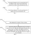
- the embodiment of the present disclosure provides a method for communication detection. As shown in FIG. 1 , the method comprises:
- the length level of the communication link is determined according to the time length of pulse data during transmission of data over the communication link, and then the corresponding detection time point on the communication link is determined according to the length level, thereby realizing dynamic adjustment of the location of the detection time point, and data waveform attenuation caused by an excessively long distance is avoided, so that the correctness of data detection is ensured, and the stability of long-distance homebus communication is improved.
- the time length of the pulse data can be the time lengths of high-level signals of the pulse data, or the time lengths of other non-zero-level signals; and the length level of the communication link is used to characterize the communication distance level of the data.
- the step S101 comprises:
- the time length of the pulse data comprises the time lengths of the high-level signals of the pulse data; and the length range of the communication link corresponding to the first length level is smaller than the length range of the communication link corresponding to the second length level.
- the value of the set threshold has a corresponding relationship with the transmission speed of the communication link.
- the value of the set threshold is also related to margin design, and certain margin time is added for the value range of the set threshold according to margin requirements.
- the value range of the margin time is 8-12 microseconds.
- the transmission time of 1 bit of data is 104 microseconds
- the time length of the high-level signal is at least 52 microseconds.
- the time length of the high-level signal is less than 52 microseconds, the high-level signal of the data on the communication link cannot be detected correctly.
- the value of the set threshold is 62 microseconds.
- the determining the time length of the pulse data specifically comprises:
- the N high-level signals can be N continuous high-level signals or N interval high-level signals.
- the outdoor unit When entering the data pulse test mode, the outdoor unit starts to send data, and the data reaches the indoor unit of the air conditioner through the communication link. After receiving the data, the indoor unit acquires the high-level signals in the pulse data, and calculates the average value of the time lengths of the N high-level signals as the time length of the pulse data.
- N is the preset number of groups. For example, 10 high-level signals are obtained, and the average value of the time lengths T of the 10 high-level signals is calculated; and the average value T 1 of the time lengths of the high-level signals is obtained, and the length level of the communication link is determined according to the relationship between T 1 and the set threshold.
- T 1 when T 1 is greater than 62 microseconds, it is determined that the communication link is at the first length level; and, when T 1 is less than 62 microseconds, it is determined that the communication link is at the second length level.
- the length range of the communication link corresponding to the first length level is smaller than the length range of the communication link corresponding to the second length level.
- the length level of the communication link can also comprise more than two levels.
- the first length level is continuously divided into more length levels according to the transmission speed of the communication link, so as to obtain a more stable and reliable time detection point.
- the step S102 comprises:
- the first detection time point is earlier than the second detection time point.
- the detection time point of the data is determined according to the mapping relationship between the length level of the communication link and the detection time point, and thus, the dynamic determination of the detection time point is realized.
- the detection time point range corresponding to the first length level is 50-55 microseconds; and the detection time point range corresponding to the second length level is 60-65 microseconds.
- the method further comprises:
- the communication distance is confirmed; and the location of the detection time point is dynamically determined, so that when the communication data is detected, the situation that the accurate data cannot be detected at the fixed detection time point due to the data waveform attenuation is avoided.
- the time length of the pulse signal of the communication data can be the time length of the high-level signal or low-level signal of the received one bit of data.
- the time length of the pulse signal of the communication data is the time length of the received one bit of high-level signal, which is 96 microseconds
- the length of the communication link corresponding to the time length of the pulse signal obtained by matching according to the second mapping relationship between the time length of the pulse signal and the length of the communication link is 200 meters; and when the time length is 70 microseconds, the length of the communication link corresponding to the time length of the pulse signal obtained by matching according to the second mapping relationship is 800 meters.
- the matching and inference of the communication distance is carried out according to the signal condition of the data received at the detection time point, so that the data waveform attenuation caused by the excessively long distance is avoided, the accuracy of data detection is ensured, and the stability of the long-distance Homebus communication is improved.
- the device for communication detection comprises:
- the length level of the communication link is determined according to the time length of the pulse data during transmission of data over the communication link, and then the corresponding detection time point on the communication link is confirmed according to the length level, thereby realizing dynamic determination of the detection time point, and data waveform attenuation caused by the excessively long distance is avoided, so that the correctness of data detection is ensured, and the stability of long-distance homebus communication is improved.
- the time length of the pulse data can be the time length of the high-level signals of the pulse data, or the time lengths of other non-zero-level signals; and the length level of the communication link is used to characterize the communication distance level of the data.
- the length level determining module 501 is configured to:
- the value of the set threshold has a corresponding relationship with the transmission speed of the communication link.
- the value of the set threshold is also related to margin design, and certain margin time is added for the value range of the set threshold according to margin requirements.
- the value range of the margin time is 8-12 microseconds.
- the transmission time of 1 bit of data is 104 microseconds
- the time length of the high-level signal is at least 52 microseconds.
- the time length of the high-level signal is less than 52 microseconds, the high-level signal of the data on the communication link cannot be detected correctly.
- the value of the set threshold is 62 microseconds.
- the length level determining module 501 is configured to:
- the outdoor unit When entering the data pulse test mode, the outdoor unit starts to send data, and the data reaches the indoor unit of the air conditioner through the communication link. After receiving the data, the indoor unit acquires the high-level signals in the pulse data, and calculates the average value of the time lengths of the N high-level signals as the time length of the pulse data.
- N is the preset number of groups.
- the length level determining module 501 obtains the 10 high-level signals, and calculates the average value of the time lengths T of the 10 high-level signals; and the average value T 1 of the time lengths of the high-level signals is obtained, and the length level of the communication link is determined according to the relationship between T 1 and the set threshold.
- T 1 when T 1 is greater than 62 microseconds, it is determined that the communication link is at the first length level; and when T 1 is less than 62 microseconds, it is determined that the communication link is at the second length level.
- the length range of the communication link corresponding to the first length level is smaller than the length range of the communication link corresponding to the second length level.
- the length level of the communication link can also comprise more than two levels.
- the length level determining module 501 continuously divides the first length level into more length levels according to the transmission speed of the communication link, so as to obtain a more stable and reliable time detection point.
- the detection time point determining module 502 comprises:
- the detection time point range corresponding to the first length level is 50-55 microseconds
- the detection time point range corresponding to the second length level is 60-65 microseconds.
- the detection time point of the data is determined according to the mapping relationship between the length level of the communication link and the detection time point, and thus, the dynamic determination of the detection time point is realized.
- the device for communication detection further comprises a communication link length determining module 503; and the communication link length determining module 503 is configured to: obtain the time length of the pulse signal of the communication data according to the communication data detected at the detection time point, and obtain the length of the communication link corresponding to the time length of the pulse signal by matching according to the second mapping relationship between the time length of the pulse signal and the length of the communication link.
- the location of the detection time point is dynamically determined, so that when the communication data is detected, the situation that the accurate data cannot be detected at the fixed detection time point due to the data waveform attenuation is avoided.
- the time length of the pulse signal of the communication data can be the time length of the high-level signal or low-level signal of the received one bit of data.
- the time length of the pulse signal of the communication data is the time length of the received one bit of high-level signal, which is 96 microseconds
- the length of the communication link corresponding to the time length of the pulse signal obtained by matching according to the second mapping relationship between the time length of the pulse signal and the length of the communication link is 200 meters; and when the time length is 70 microseconds, the length of the communication link corresponding to the time length of the pulse signal obtained by matching according to the second mapping relationship is 800 meters.
- the matching and inference of the communication distance is carried out according to the signal condition of the data received at the detection time point, so that the data waveform attenuation caused by the excessively long distance is avoided, the accuracy of data detection is ensured, and the stability of long-distance Homebus communication is improved.
- the embodiment of the present disclosure provides an air conditioner, which comprises the device for communication detection.
- the embodiment of the present disclosure provides a computer-readable storage medium which stores a computer-executable instruction; and the computer-executable instruction is configured to execute the above-mentioned method for communication detection.
- the embodiment of the present disclosure provides a computer program product; the computer program product comprises a computer program stored on the computer-readable storage medium; the computer program comprises a program instruction; and when the program instruction is executed by a computer, the computer is enabled to execute the above-mentioned method for communication detection.
- the above-mentioned computer-readable storage medium can be a transitory computer-readable storage medium or a non-transitory computer-readable storage medium.
- the embodiment of the present disclosure provides electronic equipment, the structure of which is as shown in FIG. 8 ; and the electronic equipment comprises: at least one processor 700, and a memory 701, and can also comprise a communication interface 702 and a bus 703, wherein in figure 8 , one processor 700 is taken as an example, and the processor 700, the communication interface 702, and the memory 701 can communicate with each other through the bus 703.
- the communication interface 702 can be used for information transmission.
- the processor 700 can call a logic instruction in the memory 701 so as to execute the method for communication detection in the above-mentioned embodiment.
- the above-mentioned logical instruction in the memory 701 can be implemented in the form of a software functional unit, and can be stored in the computer-readable storage medium when sold or used as an independent product.
- the memory 701 can be used to store software programs and computer-executable programs, such as program instructions/modules corresponding to the method in the embodiment of the present disclosure.
- the processor 700 executes functional applications and data processing by running the software programs, instructions, and modules stored in the memory 701, that is, the method for communication detection in the above-mentioned method embodiment is realized.
- the memory 701 can comprise a program storage area and a data storage area, wherein the program storage area can store an operating system and an application program required by at least one function; the data storage area can store data created according to the use of terminal equipment, and the like.
- the memory 701 can comprise a high-speed random access memory, and can also comprise a non-volatile memory.
- the technical solutions of the embodiments of the present disclosure can be embodied in the form of a software product.
- the computer software product is stored in one storage medium and comprises one or more instructions used for enabling one piece of computer equipment (which can be a personal computer, a server, or network equipment, etc.) to perform all or part of the steps of the method described in the embodiment of the present disclosure.
- the above-mentioned storage medium can be a non-transitory storage medium, comprising: a plurality of media capable of storing program codes, such as a U disk, a mobile hard disk, a read-only memory (ROM), a random access memory (RAM), a magnetic disk or an optical disk, or can be a transitory storage medium.
- the first element can be called the second element, and likewise, the second element can be called the first element, as long as all "first elements" are renamed consistently and all "second components" are renamed consistently.
- the first element and the second element are both elements, but they may not be the same element.
- the terms used in the present application are only used for describing the embodiments and are not used for limiting the claims. As used in the description of the embodiments and claims, unless the context clearly indicates, otherwise, the singular forms "a”, “an” and “the” are intended to also include plural forms. Similarly, the terms "and/or” as used in the present application refers to any and all possible combinations that include one or more of the associated lists.
- the term "comprise” and variants thereof “comprises” and/or comprising and the like refer to the existence of stated features, wholes, steps, operations, elements, and/or components, does not exclude the existence or addition of one or more other features, wholes, steps, operations, elements, components, and/or grouping of these. If there are no more restrictions, the element defined by the sentence “comprising a" does not exclude the existence of other same elements in the process, method, or equipment that comprise the element.
- each embodiment focuses on the differences from other embodiments, and the same or similar parts between the various embodiments can be referred to each other. For the methods, products, etc. disclosed in the embodiments, if they correspond to the method parts disclosed in the embodiments, the relevant parts can be referred to the description of the method parts.
- the disclosed method and products can be implemented in other ways.
- the device embodiments described above are merely illustrative.
- the division of the units can only be logical function division, and there may be other division modes in actual implementation, for example, multiple units or components can be combined or can be integrated into another system, or some features can be ignored or not implemented.
- the displayed or discussed mutual coupling or direct coupling or communication connection can be indirect coupling or communication connection through some interfaces, devices or units, and can be in electrical, mechanical or other forms.
- the units described as separate components may or may not be physically separated, and the components displayed as units may or may not be physical units, that is, they may be located in one place, or they may be distributed on multiple network units. Some or all of the units may be selected according to actual needs to implement the present embodiment.
- the functional units in the embodiments of the present disclosure may be integrated into one processing unit, or each unit may exist alone physically, or two or more than more units may be integrated into one unit.
- each block in the flowcharts or block diagrams can represent a module, a program segment, or part of the code; and the module, program segment, or part of the code contains one or more executable instructions for realizing the specified logical function.
- the functions marked in the blocks can also occur in an order different from the order marked in the drawings. For example, two consecutive blocks can actually be executed substantially in parallel, and they can sometimes be executed in the reverse order, depending on the functions involved.
Landscapes
- Engineering & Computer Science (AREA)
- Chemical & Material Sciences (AREA)
- Combustion & Propulsion (AREA)
- Mechanical Engineering (AREA)
- General Engineering & Computer Science (AREA)
- Signal Processing (AREA)
- Human Computer Interaction (AREA)
- Computer Networks & Wireless Communication (AREA)
- Physics & Mathematics (AREA)
- Fuzzy Systems (AREA)
- Mathematical Physics (AREA)
- Power Engineering (AREA)
- Selective Calling Equipment (AREA)
- Telephonic Communication Services (AREA)
- Dc Digital Transmission (AREA)
Abstract
Description
- The present application is proposed based on
Chinese patent application No. 201910471269.0, filed on May 31, 2019 - The present invention relates to the technical field of air conditioners, and for example relates to a method and device for communication detection and an air conditioner.
- Air conditioners include indoor units and outdoor units. For example, there are often information communication between an outdoor unit and indoor units of a multi-split air-conditioning unit. At present, the refrigerating capacity of a single module of the outdoor unit of the multi-split air-conditioning unit can reach 32 horsepower. If the four modules are combined and assembled, the refrigerating capacity of a set of outdoor unit can reach 128 horsepower, and the outdoor unit can be connected to 128 indoor units. From the perspective of development trend of the multi-split air-conditioning unit, the refrigerating capacity of the outdoor unit will continue to increase, so that one set of outdoor unit can be connected to more than 128 indoor units. The more the connected indoor units are, the longer the distance between the outdoor unit and the terminal indoor unit is.
- In the process of realizing the embodiments of the present disclosure, it is found that there are at least the following problems in the related technology: in the process of communicating between the outdoor unit and the indoor units via Homebus (communication bus), as signal refraction interference is prone to occur during long-distance communication, the longer the distance between the outdoor unit and the indoor units is, the more serious the signal attenuation of Homebus communication will be, and thus, the normal communication detection between the indoor units and the outdoor unit of the multi-split air-conditioning unit cannot be guaranteed.
- In order to have a basic understanding of some aspects of the disclosed embodiments, a brief summary is given below. The summary is not a general comment, nor is it intended to determine key/important components or describe the protection scope of these embodiments, but serves as an introduction to the following detailed description.
- The embodiments of the present disclosure provide a method and device for communication detection and an air conditioner so as to solve the problem that in the Homebus communication process in the related technology, the communication waveform attenuation occurs due to the relatively long communication distance, which results in the problem that the communication data cannot be detected normally.
- In some embodiments, the method comprises: determining a length level of a communication link according to a time length of pulse data during transmission of data over the communication link; and determining adetection time point according to the length level of the communication link.
- In some embodiments, the device comprises: a length level determining module, configured to determine the length level of the communication link according to the time length of pulse data during transmission of data over the communication link; and a detection time point determining module, configured to determine the detection time point according to the length level of the communication link.
- In some embodiments, the air conditioner comprises: the above-mentioned device for communication detection.
- Some technical solutions provided by the embodiments of the present disclosure can achieve the following technical effects:
The length level of the communication link is determined according to the time length of pulse data during transmission of data over the communication link, and then the detection time point of the data is confirmed, thereby realizing dynamic determination of the detection time point of data according to the time length of the pulse data, and data waveform attenuation caused by an excessively long distance is avoided by means of automatic adjustment of the detection time point, so that the correctness of data detection is ensured, and the stability of long-distance homebus communication is improved - The above general descriptions and the descriptions hereinafter are only exemplary and explanatory, and are not used to limit the present application.
- One or more embodiments are exemplified by corresponding drawings. These exemplified descriptions and drawings do not constitute a limitation on the embodiments. Elements with the same reference numerals in the drawings are shown as similar elements. The drawings do not constitute a scale limitation, among which,
-
FIG. 1 is a schematic flowchart of a method for communication detection provided by an embodiment of the present disclosure; -
FIG. 2 is a schematic flowchart II of a method for communication detection provided by an embodiment of the present disclosure; -
FIG. 3 is a schematic flowchart III of a method for communication detection provided by an embodiment of the present disclosure; -
FIG. 4 is a schematic flowchart IV of a method for communication detection provided by an embodiment of the present disclosure; -
FIG. 5 is a schematic diagram of a device for communication detection provided by an embodiment of the present disclosure; -
FIG. 6 is a schematic diagram II of a device for communication detection provided by an embodiment of the present disclosure; -
FIG. 7 is a schematic diagram III of a device for communication detection provided by an embodiment of the present disclosure; and -
FIG. 8 is a structural schematic diagram of electronic equipment provided by an embodiment of the present disclosure. - Reference numerals in the drawings:
501: Length level determining module; 502: Detection time point determining module; 503: Communication link length determining module; 601: Acquiring unit; 602: Judging unit; 700: Processor; 701: Memory; 702: Communication interface; 703: bus. - In order to have a more detailed understanding of the features and technical content of the embodiments of the present disclosure, the implementation of the embodiments of the present disclosure will be described in detail below with reference to the drawings. The attached drawings are for reference only, rather than limiting the embodiments of the present disclosure. In the following technical description, for the convenience of explanation, a number of details are used to provide a sufficient understanding of the disclosed embodiments. However, without these details, one or more embodiments can still be implemented. In other cases, in order to simplify the drawings, well-known structures and devices can be simplified for display.
- The embodiment of the present disclosure provides a method for communication detection. As shown in
FIG. 1 , the method comprises: - S101. determining a length level of a communication link according to a time length of pulse data during transmission of data over a communication link; and
- S102. determining a detection time point according to the length level of the communication link.
- After equipment is powered on, the data is received; the length level of the communication link is determined according to the time length of pulse data during transmission of data over the communication link, and then the corresponding detection time point on the communication link is determined according to the length level, thereby realizing dynamic adjustment of the location of the detection time point, and data waveform attenuation caused by an excessively long distance is avoided, so that the correctness of data detection is ensured, and the stability of long-distance homebus communication is improved. The time length of the pulse data can be the time lengths of high-level signals of the pulse data, or the time lengths of other non-zero-level signals; and the length level of the communication link is used to characterize the communication distance level of the data.
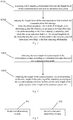
- In some embodiments, as shown in
FIG. 2 , the step S101 comprises: - S201. determining the time length of the pulse data; and
- S202. determining that the communication link is at the first length level in a case where the time length of the pulse data is greater than a set threshold, and determining that the communication link is at the second length level in a case where the time length of the pulse data is less than or equal to the set threshold.
- Wherein the time length of the pulse data comprises the time lengths of the high-level signals of the pulse data; and the length range of the communication link corresponding to the first length level is smaller than the length range of the communication link corresponding to the second length level.
- Optionally, the value of the set threshold has a corresponding relationship with the transmission speed of the communication link. Optionally, the value of the set threshold is also related to margin design, and certain margin time is added for the value range of the set threshold according to margin requirements. Optionally, the value range of the margin time is 8-12 microseconds.
- Optionally, when the baud rate of the communication link is 9600, that is, 9600 bits of data are transmitted per second, then the transmission time of 1 bit of data is 104 microseconds, it can be seen that the time length of the high-level signal is at least 52 microseconds. When the time length of the high-level signal is less than 52 microseconds, the high-level signal of the data on the communication link cannot be detected correctly. For example, when the baud rate of the communication link is 9600 and the margin time is 10 microseconds, the value of the set threshold is 62 microseconds.
- Optionally, in the step S201, the determining the time length of the pulse data specifically comprises:
- acquiring the N high-level signals of the pulse data; and,
- calculating the average value of the time lengths of the N high-level signals as the time length of the pulse data, wherein N is a natural number.
- Optionally, the N high-level signals can be N continuous high-level signals or N interval high-level signals.
- When entering the data pulse test mode, the outdoor unit starts to send data, and the data reaches the indoor unit of the air conditioner through the communication link. After receiving the data, the indoor unit acquires the high-level signals in the pulse data, and calculates the average value of the time lengths of the N high-level signals as the time length of the pulse data. Optionally, N is the preset number of groups. For example, 10 high-level signals are obtained, and the average value of the time lengths T of the 10 high-level signals is calculated; and the average value T 1 of the time lengths of the high-level signals is obtained, and the length level of the communication link is determined according to the relationship between T 1 and the set threshold.
- According to the above embodiment, that is, when T 1 is greater than 62 microseconds, it is determined that the communication link is at the first length level; and,
when T 1 is less than 62 microseconds, it is determined that the communication link is at the second length level. - Wherein the length range of the communication link corresponding to the first length level is smaller than the length range of the communication link corresponding to the second length level.
- In some embodiments, the length level of the communication link can also comprise more than two levels. For example, on the basis of the first length level obtained according to the set threshold provided in the present embodiment, the first length level is continuously divided into more length levels according to the transmission speed of the communication link, so as to obtain a more stable and reliable time detection point.
- In some embodiments, as shown in
FIG. 3 , the step S102 comprises: - S301. acquiring a first mapping relationship between the length level of the communication link and the detection time point; and
- S302. judging the length level of the communication link to which the communication link belongs, when the communication link is at the first length level, determining that the detection time point is the first detection time point according to the first mapping relationship, and when the communication link is at the second length level, determining that the detection time point is the second detection time point according to the first mapping relationship.
- Wherein the first detection time point is earlier than the second detection time point.
- The detection time point of the data is determined according to the mapping relationship between the length level of the communication link and the detection time point, and thus, the dynamic determination of the detection time point is realized.
- Optionally, the detection time point range corresponding to the first length level is 50-55 microseconds; and the detection time point range corresponding to the second length level is 60-65 microseconds.
- In some embodiments, as shown in
FIG. 4 , the method further comprises: - S401. obtaining the time length of the pulse signal of the communication data according to the communication data detected at the detection time point; and
- S402. obtaining the length of the communication link corresponding to the time length of the pulse signal by matching according to the second mapping relationship between the time length of the pulse signal and the length of the communication link.
- According to the location of the detection time point determined in the step S102, the communication distance is confirmed; and the location of the detection time point is dynamically determined, so that when the communication data is detected, the situation that the accurate data cannot be detected at the fixed detection time point due to the data waveform attenuation is avoided.
- Optionally, in the step S401, the time length of the pulse signal of the communication data can be the time length of the high-level signal or low-level signal of the received one bit of data. For example, when the time length of the pulse signal of the communication data is the time length of the received one bit of high-level signal, which is 96 microseconds, the length of the communication link corresponding to the time length of the pulse signal obtained by matching according to the second mapping relationship between the time length of the pulse signal and the length of the communication link is 200 meters; and when the time length is 70 microseconds, the length of the communication link corresponding to the time length of the pulse signal obtained by matching according to the second mapping relationship is 800 meters.
- There is no need to add external equipment. The matching and inference of the communication distance is carried out according to the signal condition of the data received at the detection time point, so that the data waveform attenuation caused by the excessively long distance is avoided, the accuracy of data detection is ensured, and the stability of the long-distance Homebus communication is improved.
- The embodiment of the present disclosure provides a device for communication detection. As shown in
FIG. 5 , the device for communication detection comprises: - a length
level determining module 501, configured to determine the length level of the communication link according to the time length of the pulse data during transmission of data over the communication link; and - a detection time
point determining module 502, configured to determine the detection time point according to the length level of the communication link. - After the equipment is powered on, the data is received; the length level of the communication link is determined according to the time length of the pulse data during transmission of data over the communication link, and then the corresponding detection time point on the communication link is confirmed according to the length level, thereby realizing dynamic determination of the detection time point, and data waveform attenuation caused by the excessively long distance is avoided, so that the correctness of data detection is ensured, and the stability of long-distance homebus communication is improved. Wherein the time length of the pulse data can be the time length of the high-level signals of the pulse data, or the time lengths of other non-zero-level signals; and the length level of the communication link is used to characterize the communication distance level of the data.
- In some embodiments, the length
level determining module 501 is configured to: - determine the time length of the pulse data,
- determine that the communication link is at the first length level in a case where the effective time signal length when the data is transmitted on the communication link is greater than the set threshold, and
- determine that the communication link is at the second length level in a case where the effective time signal length when the data is transmitted on the communication link is less than or equal to the set threshold; and
- wherein the time length of the pulse data comprises the time lengths of the high-level signals of the pulse data; and the length range of the communication link corresponding to the first length level is smaller than the length range of the communication link corresponding to the second length level.
- Optionally, in the length
level determining module 501, the value of the set threshold has a corresponding relationship with the transmission speed of the communication link. Optionally, the value of the set threshold is also related to margin design, and certain margin time is added for the value range of the set threshold according to margin requirements. Optionally, the value range of the margin time is 8-12 microseconds. - Optionally, when the baud rate of the communication link is 9600, that is, 9600 bits of data are transmitted per second, then the transmission time of 1 bit of data is 104 microseconds, it can be seen that the time length of the high-level signal is at least 52 microseconds. When the time length of the high-level signal is less than 52 microseconds, the high-level signal of the data on the communication link cannot be detected correctly. For example, when the baud rate of the communication link is 9600 and the margin time is 10 microseconds, the value of the set threshold is 62 microseconds.
- In some embodiments, the length
level determining module 501 is configured to: - acquire the N high-level signals of the pulse data, and
- calculate the average value of the time lengths of the N high-level signals as the time length of the pulse data, wherein N is a natural number.
- When entering the data pulse test mode, the outdoor unit starts to send data, and the data reaches the indoor unit of the air conditioner through the communication link. After receiving the data, the indoor unit acquires the high-level signals in the pulse data, and calculates the average value of the time lengths of the N high-level signals as the time length of the pulse data. Optionally, N is the preset number of groups. For example, the length
level determining module 501 obtains the 10 high-level signals, and calculates the average value of the time lengths T of the 10 high-level signals; and the average value T 1 of the time lengths of the high-level signals is obtained, and the length level of the communication link is determined according to the relationship between T 1 and the set threshold. - According to the above embodiment, that is, when T 1 is greater than 62 microseconds, it is determined that the communication link is at the first length level; and
when T 1 is less than 62 microseconds, it is determined that the communication link is at the second length level. - Wherein the length range of the communication link corresponding to the first length level is smaller than the length range of the communication link corresponding to the second length level.
- In some embodiments, the length level of the communication link can also comprise more than two levels. For example, on the basis of the first length level obtained according to the set threshold, the length
level determining module 501 continuously divides the first length level into more length levels according to the transmission speed of the communication link, so as to obtain a more stable and reliable time detection point. - In some embodiments, as shown in
FIG. 6 , the detection timepoint determining module 502 comprises: - an acquiring
unit 601, configured to acquire the first mapping relationship between the length level of the communication link and the detection time point; - a judging
unit 602, configured to judge the length level of the communication link to which the communication link belongs, determine that the detection time point is the first detection time point according to the first mapping relationship when the communication link is at the first length level, and determine that the detection time point is the second detection time point according to the first mapping relationship when the communication link is at the second length level; and - wherein the first detection time point is earlier than the second detection time point.
- Optionally, according to the above-mentioned embodiment, the detection time point range corresponding to the first length level is 50-55 microseconds, and the detection time point range corresponding to the second length level is 60-65 microseconds.
- The detection time point of the data is determined according to the mapping relationship between the length level of the communication link and the detection time point, and thus, the dynamic determination of the detection time point is realized.
- In some embodiments, as shown in
FIG. 7 , on the basis of the above-mentioned embodiments, the device for communication detection further comprises a communication linklength determining module 503; and the communication linklength determining module 503 is configured to: obtain the time length of the pulse signal of the communication data according to the communication data detected at the detection time point, and
obtain the length of the communication link corresponding to the time length of the pulse signal by matching according to the second mapping relationship between the time length of the pulse signal and the length of the communication link. - The location of the detection time point is dynamically determined, so that when the communication data is detected, the situation that the accurate data cannot be detected at the fixed detection time point due to the data waveform attenuation is avoided.
- Optionally, the time length of the pulse signal of the communication data can be the time length of the high-level signal or low-level signal of the received one bit of data. For example, when the time length of the pulse signal of the communication data is the time length of the received one bit of high-level signal, which is 96 microseconds, the length of the communication link corresponding to the time length of the pulse signal obtained by matching according to the second mapping relationship between the time length of the pulse signal and the length of the communication link is 200 meters; and when the time length is 70 microseconds, the length of the communication link corresponding to the time length of the pulse signal obtained by matching according to the second mapping relationship is 800 meters.
- There is no need to add external equipment. The matching and inference of the communication distance is carried out according to the signal condition of the data received at the detection time point, so that the data waveform attenuation caused by the excessively long distance is avoided, the accuracy of data detection is ensured, and the stability of long-distance Homebus communication is improved.
- The embodiment of the present disclosure provides an air conditioner, which comprises the device for communication detection.
- The embodiment of the present disclosure provides a computer-readable storage medium which stores a computer-executable instruction; and the computer-executable instruction is configured to execute the above-mentioned method for communication detection.
- The embodiment of the present disclosure provides a computer program product; the computer program product comprises a computer program stored on the computer-readable storage medium; the computer program comprises a program instruction; and when the program instruction is executed by a computer, the computer is enabled to execute the above-mentioned method for communication detection.
- The above-mentioned computer-readable storage medium can be a transitory computer-readable storage medium or a non-transitory computer-readable storage medium.
- The embodiment of the present disclosure provides electronic equipment, the structure of which is as shown in
FIG. 8 ; and the electronic equipment comprises:
at least oneprocessor 700, and amemory 701, and can also comprise acommunication interface 702 and abus 703, wherein infigure 8 , oneprocessor 700 is taken as an example, and theprocessor 700, thecommunication interface 702, and thememory 701 can communicate with each other through thebus 703. Thecommunication interface 702 can be used for information transmission. Theprocessor 700 can call a logic instruction in thememory 701 so as to execute the method for communication detection in the above-mentioned embodiment. - In addition, the above-mentioned logical instruction in the
memory 701 can be implemented in the form of a software functional unit, and can be stored in the computer-readable storage medium when sold or used as an independent product. - As the computer-readable storage medium, the
memory 701 can be used to store software programs and computer-executable programs, such as program instructions/modules corresponding to the method in the embodiment of the present disclosure. Theprocessor 700 executes functional applications and data processing by running the software programs, instructions, and modules stored in thememory 701, that is, the method for communication detection in the above-mentioned method embodiment is realized. - The
memory 701 can comprise a program storage area and a data storage area, wherein the program storage area can store an operating system and an application program required by at least one function; the data storage area can store data created according to the use of terminal equipment, and the like. In addition, thememory 701 can comprise a high-speed random access memory, and can also comprise a non-volatile memory. - The technical solutions of the embodiments of the present disclosure can be embodied in the form of a software product. The computer software product is stored in one storage medium and comprises one or more instructions used for enabling one piece of computer equipment (which can be a personal computer, a server, or network equipment, etc.) to perform all or part of the steps of the method described in the embodiment of the present disclosure. The above-mentioned storage medium can be a non-transitory storage medium, comprising: a plurality of media capable of storing program codes, such as a U disk, a mobile hard disk, a read-only memory (ROM), a random access memory (RAM), a magnetic disk or an optical disk, or can be a transitory storage medium.
- The above description and drawings fully illustrate the embodiments of the present disclosure for enabling those skilled in the art to practice them. Other embodiments can include structural, logical, electrical, procedural, and other changes. The embodiments only represent possible changes. Unless explicitly required, individual components and functions are optional, and the order of operations can be changed. Parts and features of some embodiments can be included in or substitute for parts and features of other embodiments. The scope of the embodiments of the present disclosure comprises the entire scope of the claims and all available equivalents of the claims. When the terms such as "first" and "second" are used in the present application, although the terms "first" and "second" can be used for describing various elements in the present application, these elements should not be limited by these terms. These terms are only used for distinguishing one element from another element. For example, without changing the meaning of the description, the first element can be called the second element, and likewise, the second element can be called the first element, as long as all "first elements" are renamed consistently and all "second components" are renamed consistently. The first element and the second element are both elements, but they may not be the same element. Moreover, the terms used in the present application are only used for describing the embodiments and are not used for limiting the claims. As used in the description of the embodiments and claims, unless the context clearly indicates, otherwise, the singular forms "a", "an" and "the" are intended to also include plural forms. Similarly, the terms "and/or" as used in the present application refers to any and all possible combinations that include one or more of the associated lists. In addition, when used in the present application, the term "comprise" and variants thereof "comprises" and/or comprising and the like refer to the existence of stated features, wholes, steps, operations, elements, and/or components, does not exclude the existence or addition of one or more other features, wholes, steps, operations, elements, components, and/or grouping of these. If there are no more restrictions, the element defined by the sentence "comprising a..." does not exclude the existence of other same elements in the process, method, or equipment that comprise the element. In the present disclosure, each embodiment focuses on the differences from other embodiments, and the same or similar parts between the various embodiments can be referred to each other. For the methods, products, etc. disclosed in the embodiments, if they correspond to the method parts disclosed in the embodiments, the relevant parts can be referred to the description of the method parts.
- Those skilled in the art may realize that units and algorithm steps of the examples described in combination with the embodiments disclosed herein can be implemented by electronic hardware or a combination of computer software and the electronic hardware. Whether these functions are executed by hardware or software may depend on the specific application and design constraint conditions of the technical solution. The technical personnel can use different methods for each specific application to realize the described functions, but such realization should not be considered as going beyond the scope of the embodiments of the present disclosure. The technical personnel can clearly understand that for the convenience and conciseness of the description, the specific working process of the above-described system, device, and unit can refer to the corresponding process in the above-mentioned method embodiment, which is not repeated here.
- In the embodiments disclosed herein, the disclosed method and products (comprising but not limited to devices, equipment, etc.) can be implemented in other ways. For example, the device embodiments described above are merely illustrative. For example, the division of the units can only be logical function division, and there may be other division modes in actual implementation, for example, multiple units or components can be combined or can be integrated into another system, or some features can be ignored or not implemented. In addition, the displayed or discussed mutual coupling or direct coupling or communication connection can be indirect coupling or communication connection through some interfaces, devices or units, and can be in electrical, mechanical or other forms. The units described as separate components may or may not be physically separated, and the components displayed as units may or may not be physical units, that is, they may be located in one place, or they may be distributed on multiple network units. Some or all of the units may be selected according to actual needs to implement the present embodiment. In addition, the functional units in the embodiments of the present disclosure may be integrated into one processing unit, or each unit may exist alone physically, or two or more than more units may be integrated into one unit.
- The flowcharts and block diagrams in the drawings show the possible implemented architecture, functions, and operations of the system, method, and computer program product according to the embodiments of the present disclosure. In this regard, each block in the flowcharts or block diagrams can represent a module, a program segment, or part of the code; and the module, program segment, or part of the code contains one or more executable instructions for realizing the specified logical function. In some alternative implementations, the functions marked in the blocks can also occur in an order different from the order marked in the drawings. For example, two consecutive blocks can actually be executed substantially in parallel, and they can sometimes be executed in the reverse order, depending on the functions involved. In the descriptions corresponding to the flowcharts and block diagrams in the drawings, the operations or steps corresponding to different blocks can also occur in an order different than the order disclosed in the description, and sometimes there is no specific order between different operations or steps.. For example, two consecutive operations or steps can actually be performed substantially in parallel, and they can sometimes be performed in the reverse order, depending on the functions involved. Each block in the block diagrams and/or flowcharts, and the combination of the blocks in the block diagrams and/or flowcharts, can be implemented by a dedicated hardware-based system which performs the specified functions or actions, or can be implemented by a combination of dedicated hardware and computer instructions.
Claims (11)
- A method for communication detection, comprising:determining a length level of a communication link according to a time length of pulse data during transmission of data over the communication link; anddetermining a detection time point according to the length level of the communication link.
- The method of claim 1, wherein the determining a length level of a communication link according to a time length of pulse data during transmission of data over the communication link comprises:determining the time length of the pulse data;determining that the communication link is at the first length level in a case where the time length of the pulse data is greater than a set threshold;determining that the communication link is at the second length level in a case where the time length of the pulse data is less than or equal to the set threshold; andwherein the time length of the pulse data comprises the time lengths of high-level signals of the pulse data, and the length range of the communication link corresponding to the first length level is smaller than the length range of the communication link corresponding to the second length level.
- The method of claim 2, wherein the determining the time length of the pulse data specially comprises:acquiring the N high-level signals of the pulse data; andcalculating the average value of the time lengths of the N high-level signals as the time length of the pulse data, wherein N is a natural number.
- The method of claim 1, wherein the determining a detection time point according to the length level of the communication link comprises:acquiring a first mapping relationship between the length level of the communication link and the detection time point;judging the length level of the communication link to which the communication link belongs, when the communication link is at the first length level, determining that the detection time point is the first detection time point according to the first mapping relationship, and when the communication link is at the second length level, determining that the detection time point is the second detection time point according to the first mapping relationship; andwherein the first detection time point is earlier than the second detection time point.
- The method of any one of claims 1 to 4, further comprising:obtaining the time length of a pulse signal of the communication data according to communication data detected at the detection time point; andobtaining the length of the communication link corresponding to the time length of the pulse signal by matching according to the second mapping relationship between the time length of the pulse signal and the length of the communication link.
- A device for communication detection, comprising:a length level determining module, configured to determine the length level of the communication link according to the time length of the pulse data during transmission of data over the communication link; anda detection time point determining module, configured to determine the detection time point according to the length level of the communication link.
- The device of the claim 6, wherein the length level determining module is configured to:determine the time length of the pulse data,determine that the communication link is at the first length level in a case where the effective time signal length when the data is transmitted on the communication link is greater than the set threshold, anddetermine that the communication link is at the second length level in a case where the effective time signal length when the data is transmitted on the communication link is less than or equal to the set threshold; andwherein the time length of the pulse data comprises the time lengths of the high-level signals of the pulse data, and the length range of the communication link corresponding to the first length level is smaller than the length range of the communication link corresponding to the second length level.
- The device of the claim 7, wherein the length level determining module is configured to:acquire the N high-level signals of the pulse data, andcalculate the average value of the time lengths of the N high-level signals as the time length of the pulse data; andwherein N is a natural number.
- The device of the claim 8, wherein the detection time point determining module comprises:an acquiring unit, configured to acquire the first mapping relationship between the length level of the communication link and the detection time point;a judging unit, configured to judge the length level of the communication link to which the communication link belongs, determine that the detection time point is the first detection time point according to the first mapping relationship when the communication link is at the first length level, and determine that the detection time point is the second detection time point according to the first mapping relationship when the communication link is at the second length level; andwherein the first detection time point is earlier than the second detection time point.
- The device of any one of claims 6 to 9, further comprising a communication link length determining module which is configured to:obtain the time length of the pulse signal of the communication data according to communication data detected at the detection time point, andobtain the length of the communication link corresponding to the time length of the pulse signal by matching according to the second mapping relationship between the time length of the pulse signal and the length of the communication link.
- An air conditioner, comprising the device for communication detection of any one of claims 6 to 10.
Applications Claiming Priority (2)
| Application Number | Priority Date | Filing Date | Title |
|---|---|---|---|
| CN201910471269.0A CN112013506B (en) | 2019-05-31 | 2019-05-31 | Communication detection method and device and air conditioner |
| PCT/CN2020/090426 WO2020238648A1 (en) | 2019-05-31 | 2020-05-15 | Method and device for communication detection, and air conditioner |
Publications (3)
| Publication Number | Publication Date |
|---|---|
| EP3869115A1 true EP3869115A1 (en) | 2021-08-25 |
| EP3869115A4 EP3869115A4 (en) | 2022-03-02 |
| EP3869115B1 EP3869115B1 (en) | 2025-01-01 |
Family
ID=73506149
Family Applications (1)
| Application Number | Title | Priority Date | Filing Date |
|---|---|---|---|
| EP20815617.4A Active EP3869115B1 (en) | 2019-05-31 | 2020-05-15 | Method and device for communication detection, and air conditioner |
Country Status (5)
| Country | Link |
|---|---|
| US (1) | US11611455B2 (en) |
| EP (1) | EP3869115B1 (en) |
| CN (1) | CN112013506B (en) |
| ES (1) | ES3008844T3 (en) |
| WO (1) | WO2020238648A1 (en) |
Cited By (1)
| Publication number | Priority date | Publication date | Assignee | Title |
|---|---|---|---|---|
| US20220029860A1 (en) * | 2019-05-31 | 2022-01-27 | Qingdao Haier Air-Conditioning Electronic Co., Ltd. | Method and device for communication detection and air conditioner |
Family Cites Families (65)
| Publication number | Priority date | Publication date | Assignee | Title |
|---|---|---|---|---|
| DE4102151A1 (en) * | 1991-01-25 | 1992-07-30 | Philips Patentverwaltung | RECEIVER FOR A DIGITAL TRANSMISSION SYSTEM |
| JPH05244175A (en) * | 1992-03-02 | 1993-09-21 | Daikin Ind Ltd | Transmitting device |
| AU2632601A (en) * | 2000-01-07 | 2001-07-24 | Aware, Inc. | Systems and methods for loop length and bridged tap length determination of a transmission line |
| ATE367690T1 (en) * | 2001-02-24 | 2007-08-15 | Ibm | DATA COLLECTION TECHNOLOGY FOR FAST SIGNING |
| JP3870280B2 (en) | 2004-01-15 | 2007-01-17 | 株式会社日立製作所 | Air conditioner and power line communication system |
| US7216016B2 (en) * | 2004-01-20 | 2007-05-08 | Carrier Corporation | Failure mode for HVAC system |
| JP2007315709A (en) * | 2006-05-26 | 2007-12-06 | Max Co Ltd | Bathroom air conditioner |
| JP2009012573A (en) * | 2007-07-03 | 2009-01-22 | Calsonic Kansei Corp | Air conditioner controller for vehicle |
| CN101635694A (en) * | 2008-07-21 | 2010-01-27 | 中兴通讯股份有限公司 | Adaptive equalizer and method for adaptive equalization |
| CN101873155A (en) * | 2009-04-22 | 2010-10-27 | 雷凌科技股份有限公司 | Method and device for estimating transmission line length |
| JP5060534B2 (en) * | 2009-09-09 | 2012-10-31 | 日立アプライアンス株式会社 | Air conditioner |
| CN101706144A (en) * | 2009-11-05 | 2010-05-12 | 宁波奥克斯空调有限公司 | Method for judging communication failures of indoor unit and outdoor unit of varied-frequency air conditioner |
| JP2011185532A (en) * | 2010-03-09 | 2011-09-22 | Panasonic Corp | Communication control circuit of air conditioner |
| JP5195814B2 (en) * | 2010-04-30 | 2013-05-15 | ダイキン工業株式会社 | Air conditioning apparatus and control method thereof |
| JP2012163232A (en) * | 2011-02-04 | 2012-08-30 | Panasonic Corp | Communication control circuit of air conditioner |
| WO2012172690A1 (en) * | 2011-06-17 | 2012-12-20 | 三菱電機株式会社 | Air-conditioning management device, air-conditioning management method, and program |
| JP6041866B2 (en) * | 2012-04-20 | 2016-12-14 | 三菱電機株式会社 | Power conversion device, motor drive control device including the power conversion device, blower and compressor including the motor drive control device, and air conditioner including the blower or compressor |
| JP5993621B2 (en) * | 2012-06-04 | 2016-09-14 | アズビル株式会社 | Request discrimination device, air conditioning control system, demand discrimination method and air conditioning control method |
| CN103471201B (en) * | 2012-06-08 | 2016-01-20 | 海尔集团公司 | Communication circuit of air conditioner |
| US9729362B1 (en) * | 2013-03-20 | 2017-08-08 | Georgia Tech Research Corporation | Systems and methods for autonomous signal modulation format identification |
| CN104076328B (en) * | 2013-03-29 | 2016-12-28 | 日电(中国)有限公司 | The method and device of signal detection |
| EP3055851B1 (en) * | 2013-10-07 | 2020-02-26 | Google LLC | Smart-home hazard detector providing context specific features and/or pre-alarm configurations |
| JP6290028B2 (en) * | 2014-07-30 | 2018-03-07 | 株式会社東芝 | Motor control device, air conditioner, washing machine and refrigerator |
| DE112014007132B4 (en) * | 2014-11-04 | 2022-03-31 | Mitsubishi Electric Corporation | Communication system, signal transmission method and air conditioning |
| CN104502531A (en) * | 2014-11-21 | 2015-04-08 | 小米科技有限责任公司 | Air quality acquisition method and device thereof |
| CN104896656B (en) * | 2015-05-11 | 2018-04-06 | 小米科技有限责任公司 | Method and device for starting air conditioner |
| US10474627B2 (en) * | 2015-10-08 | 2019-11-12 | Via Alliance Semiconductor Co., Ltd. | Neural network unit with neural memory and array of neural processing units that collectively shift row of data received from neural memory |
| CN106485319B (en) * | 2015-10-08 | 2019-02-12 | 上海兆芯集成电路有限公司 | Neural network units with neural processing units dynamically configurable to execute on multiple data sizes |
| JP6740602B2 (en) * | 2015-12-11 | 2020-08-19 | ダイキン工業株式会社 | Information processing equipment |
| CN108702311B (en) * | 2016-03-10 | 2020-11-27 | 三菱电机株式会社 | Receiving device and method for estimating situation detection time |
| CN105783194B (en) * | 2016-04-14 | 2018-12-18 | 广东美的暖通设备有限公司 | Multi-online air-conditioning system and its communication means |
| CN106093850A (en) * | 2016-06-04 | 2016-11-09 | 四川中电昆辰科技有限公司 | Timing acquisition device and positioner thereof and method |
| CN106209496A (en) * | 2016-06-23 | 2016-12-07 | 珠海格力电器股份有限公司 | Communication abnormity detection device and method |
| US10070092B2 (en) * | 2016-07-22 | 2018-09-04 | Sony Corporation | Directional remote control based on ranging |
| CN106452671B (en) * | 2016-09-28 | 2020-09-18 | 青岛海尔空调电子有限公司 | Multi-line internal and external communication method |
| CN106545955B (en) * | 2016-10-08 | 2021-05-04 | 珠海格力电器股份有限公司 | Communication relay device and method and air conditioner |
| CN107101348B (en) * | 2017-03-27 | 2020-12-08 | 青岛海尔空调电子有限公司 | Indoor and outdoor unit communication method and device for air-conditioning multi-connection unit and air-conditioning unit |
| US9967024B1 (en) * | 2017-04-11 | 2018-05-08 | Macom Technology Solutions Holdings, Inc. | Automatic optical reflectometer power adjustment |
| CN107819512B (en) * | 2017-11-03 | 2020-06-30 | 深圳大希创新科技有限公司 | Time-delay radiator capable of self-adaptive adjustment along with distance and time-delay radiation method |
| CN108050664A (en) * | 2017-12-13 | 2018-05-18 | 广东美的制冷设备有限公司 | Acquisition methods, device and the storage medium of conditioner operating parameter |
| WO2019164677A1 (en) * | 2018-02-20 | 2019-08-29 | Johnson Controls Technology Company | Building management system network with power conservation via adaptive use of network protocols |
| CN108489007A (en) * | 2018-03-20 | 2018-09-04 | 深圳明创自控技术有限公司 | A kind of adjustable smart home of environment |
| CN108488914A (en) * | 2018-04-13 | 2018-09-04 | 珠海格力电器股份有限公司 | Air conditioning unit and operation method and device of air conditioning unit |
| CN109028517B (en) * | 2018-07-31 | 2020-10-20 | 广东美的制冷设备有限公司 | Detection method of filter net cleanliness, air conditioner and computer readable storage medium |
| CN110873419B (en) * | 2018-08-31 | 2021-08-24 | 重庆海尔空调器有限公司 | A kind of air conditioner and its self-cleaning control method |
| CN110873422B (en) * | 2018-08-31 | 2022-04-15 | 青岛海尔空调器有限总公司 | Air conditioner and self-cleaning control method thereof |
| CN110873407B (en) * | 2018-08-31 | 2022-03-29 | 青岛海尔空调器有限总公司 | Air conditioner and self-cleaning control method thereof |
| CN110873426B (en) * | 2018-08-31 | 2022-04-19 | 青岛海尔空调器有限总公司 | Air conditioner and self-cleaning control method thereof |
| CN110873417B (en) * | 2018-08-31 | 2022-01-21 | 青岛海尔空调器有限总公司 | Air conditioner and self-cleaning control method thereof |
| CN109323361B (en) * | 2018-09-30 | 2021-08-20 | 广东美的制冷设备有限公司 | Method and system for detecting operation capacity of air conditioner |
| CN109059233B (en) * | 2018-10-24 | 2024-03-15 | 奥克斯空调股份有限公司 | Air duct structure and air conditioner |
| CN108954754B (en) * | 2018-10-24 | 2023-09-15 | 奥克斯空调股份有限公司 | Air duct structure and air conditioner |
| EP3906646A4 (en) * | 2019-01-04 | 2022-08-10 | Telefonaktiebolaget Lm Ericsson (Publ) | Method and receiving node for determining a channel window length |
| CN110030688B (en) * | 2019-03-21 | 2020-09-25 | 青岛海尔空调器有限总公司 | Air conditioner control method and control device |
| CN109959127B (en) * | 2019-04-28 | 2020-06-16 | 珠海格力电器股份有限公司 | Unit control method and device and air conditioner |
| CN110173809B (en) * | 2019-05-21 | 2021-03-19 | 广东美的制冷设备有限公司 | Dust accumulation detection method, device and storage medium for outdoor unit of air conditioner |
| CN112013506B (en) * | 2019-05-31 | 2022-02-25 | 青岛海尔空调电子有限公司 | Communication detection method and device and air conditioner |
| CN112013505B (en) * | 2019-05-31 | 2021-11-02 | 青岛海尔空调电子有限公司 | Method and device for controlling communication compensation, air conditioner |
| CN112443949B (en) * | 2019-08-30 | 2022-09-27 | 广东美的制冷设备有限公司 | Control method and control device of air conditioner and readable storage medium |
| CN110822647B (en) * | 2019-11-25 | 2021-12-17 | 广东美的制冷设备有限公司 | Control method of air conditioner, air conditioner and storage medium |
| EP3940497B1 (en) * | 2020-07-15 | 2023-03-15 | Siemens Schweiz AG | Maximum flow setting |
| CN112556105B (en) * | 2020-12-09 | 2022-05-31 | 广东美的暖通设备有限公司 | Control method, control device, communication system and storage medium for communication equipment |
| CN112984718A (en) * | 2020-12-18 | 2021-06-18 | 四川虹美智能科技有限公司 | Intelligent air conditioner control method, device and system based on human body tracking |
| CN113915741B (en) * | 2021-09-02 | 2023-05-12 | 远景智能国际私人投资有限公司 | Instruction sending method, device and system |
| CN114017846B (en) * | 2021-12-03 | 2022-10-28 | 青岛海信网络能源股份有限公司 | Control method of gravity heat pipe inter-row air conditioner and gravity heat pipe inter-row air conditioner |
-
2019
- 2019-05-31 CN CN201910471269.0A patent/CN112013506B/en active Active
-
2020
- 2020-05-15 WO PCT/CN2020/090426 patent/WO2020238648A1/en not_active Ceased
- 2020-05-15 ES ES20815617T patent/ES3008844T3/en active Active
- 2020-05-15 EP EP20815617.4A patent/EP3869115B1/en active Active
- 2020-05-15 US US17/297,544 patent/US11611455B2/en active Active
Cited By (2)
| Publication number | Priority date | Publication date | Assignee | Title |
|---|---|---|---|---|
| US20220029860A1 (en) * | 2019-05-31 | 2022-01-27 | Qingdao Haier Air-Conditioning Electronic Co., Ltd. | Method and device for communication detection and air conditioner |
| US11611455B2 (en) * | 2019-05-31 | 2023-03-21 | Qingdao Haier Air-Conditioning Electronic Co., Ltd. | Method and device for communication detection and air conditioner |
Also Published As
| Publication number | Publication date |
|---|---|
| ES3008844T3 (en) | 2025-03-25 |
| CN112013506A (en) | 2020-12-01 |
| EP3869115A4 (en) | 2022-03-02 |
| US20220029860A1 (en) | 2022-01-27 |
| US11611455B2 (en) | 2023-03-21 |
| EP3869115B1 (en) | 2025-01-01 |
| WO2020238648A1 (en) | 2020-12-03 |
| CN112013506B (en) | 2022-02-25 |
Similar Documents
| Publication | Publication Date | Title |
|---|---|---|
| CA1315008C (en) | System permitting peripheral interchangeability | |
| US8935576B2 (en) | Automated cabling process for a complex environment | |
| JP2010088106A (en) | Managing timing of protocol stack | |
| CN107147553B (en) | Method, device and equipment for adjusting Baud rate and frame format of slave station | |
| EP3860296A1 (en) | Method for transmitting downlink control channel, terminal and network side device | |
| EP3873044B1 (en) | Method and device for controlling communication compensation, and air conditioner | |
| US11611455B2 (en) | Method and device for communication detection and air conditioner | |
| EP4589441A1 (en) | Signal transmission system and method | |
| CN110177035B (en) | Data receiving and sending method, device and data receiving and sending system | |
| CN107608711A (en) | Upgrade method, device, system and electronic equipment | |
| CN105764094A (en) | Hybrid load balancing method and device | |
| CN114623559A (en) | Method and device for detecting refrigerant leakage, air conditioner and storage medium | |
| CN106304389B (en) | A kind of indicating means and device of resource collision | |
| CN104679687B (en) | A kind of method and device for identifying interrupt source | |
| CN102204199A (en) | Bit inversion for communication interface | |
| KR101649790B1 (en) | Feeder terminal unit | |
| CN116010292A (en) | Memory access control method, device, electronic device and storage medium | |
| EP1679611A2 (en) | Calculator device having a USB connection | |
| JP2022165624A (en) | Terminal controller, elevator control system, and communication speed setting method | |
| KR101218543B1 (en) | Controller for 9-bit serial communication system | |
| CN117319214B (en) | PCIE transmission bandwidth processing method, PCIE terminal equipment and electronic equipment | |
| CN118208805B (en) | Serial port multiplexing communication method, device, air conditioner and computer readable storage medium | |
| CN103164381A (en) | PHY adjustment method and system of serial attached small computer system interface (SCSI) (SAS) expander equipment | |
| AU2018408003A1 (en) | Data transmission method, apparatus, computer device and storage medium | |
| CN107317727A (en) | Loop testing method, device and router |
Legal Events
| Date | Code | Title | Description |
|---|---|---|---|
| STAA | Information on the status of an ep patent application or granted ep patent |
Free format text: STATUS: THE INTERNATIONAL PUBLICATION HAS BEEN MADE |
|
| PUAI | Public reference made under article 153(3) epc to a published international application that has entered the european phase |
Free format text: ORIGINAL CODE: 0009012 |
|
| STAA | Information on the status of an ep patent application or granted ep patent |
Free format text: STATUS: REQUEST FOR EXAMINATION WAS MADE |
|
| 17P | Request for examination filed |
Effective date: 20210521 |
|
| AK | Designated contracting states |
Kind code of ref document: A1 Designated state(s): AL AT BE BG CH CY CZ DE DK EE ES FI FR GB GR HR HU IE IS IT LI LT LU LV MC MK MT NL NO PL PT RO RS SE SI SK SM TR |
|
| STAA | Information on the status of an ep patent application or granted ep patent |
Free format text: STATUS: EXAMINATION IS IN PROGRESS |
|
| A4 | Supplementary search report drawn up and despatched |
Effective date: 20220128 |
|
| RIC1 | Information provided on ipc code assigned before grant |
Ipc: F24F 11/61 20180101ALI20220124BHEP Ipc: F24F 11/64 20180101ALI20220124BHEP Ipc: F24F 11/49 20180101ALI20220124BHEP Ipc: F24F 11/30 20180101ALI20220124BHEP Ipc: F24F 11/88 20180101ALI20220124BHEP Ipc: G08C 19/16 20060101ALI20220124BHEP Ipc: F24F 3/06 20060101ALI20220124BHEP Ipc: H04B 3/04 20060101ALI20220124BHEP Ipc: F24F 11/56 20180101AFI20220124BHEP |
|
| 17Q | First examination report despatched |
Effective date: 20220223 |
|
| DAV | Request for validation of the european patent (deleted) | ||
| DAX | Request for extension of the european patent (deleted) | ||
| GRAP | Despatch of communication of intention to grant a patent |
Free format text: ORIGINAL CODE: EPIDOSNIGR1 |
|
| STAA | Information on the status of an ep patent application or granted ep patent |
Free format text: STATUS: GRANT OF PATENT IS INTENDED |
|
| INTG | Intention to grant announced |
Effective date: 20240723 |
|
| GRAS | Grant fee paid |
Free format text: ORIGINAL CODE: EPIDOSNIGR3 |
|
| GRAA | (expected) grant |
Free format text: ORIGINAL CODE: 0009210 |
|
| STAA | Information on the status of an ep patent application or granted ep patent |
Free format text: STATUS: THE PATENT HAS BEEN GRANTED |
|
| P01 | Opt-out of the competence of the unified patent court (upc) registered |
Free format text: CASE NUMBER: APP_59230/2024 Effective date: 20241030 |
|
| AK | Designated contracting states |
Kind code of ref document: B1 Designated state(s): AL AT BE BG CH CY CZ DE DK EE ES FI FR GB GR HR HU IE IS IT LI LT LU LV MC MK MT NL NO PL PT RO RS SE SI SK SM TR |
|
| REG | Reference to a national code |
Ref country code: GB Ref legal event code: FG4D |
|
| REG | Reference to a national code |
Ref country code: DE Ref legal event code: R096 Ref document number: 602020044172 Country of ref document: DE |
|
| REG | Reference to a national code |
Ref country code: CH Ref legal event code: EP |
|
| REG | Reference to a national code |
Ref country code: IE Ref legal event code: FG4D |
|
| REG | Reference to a national code |
Ref country code: ES Ref legal event code: FG2A Ref document number: 3008844 Country of ref document: ES Kind code of ref document: T3 Effective date: 20250325 |
|
| REG | Reference to a national code |
Ref country code: LT Ref legal event code: MG9D |
|
| REG | Reference to a national code |
Ref country code: NL Ref legal event code: MP Effective date: 20250101 |
|
| REG | Reference to a national code |
Ref country code: AT Ref legal event code: MK05 Ref document number: 1756599 Country of ref document: AT Kind code of ref document: T Effective date: 20250101 |
|
| PG25 | Lapsed in a contracting state [announced via postgrant information from national office to epo] |
Ref country code: NL Free format text: LAPSE BECAUSE OF FAILURE TO SUBMIT A TRANSLATION OF THE DESCRIPTION OR TO PAY THE FEE WITHIN THE PRESCRIBED TIME-LIMIT Effective date: 20250101 |
|
| PG25 | Lapsed in a contracting state [announced via postgrant information from national office to epo] |
Ref country code: FI Free format text: LAPSE BECAUSE OF FAILURE TO SUBMIT A TRANSLATION OF THE DESCRIPTION OR TO PAY THE FEE WITHIN THE PRESCRIBED TIME-LIMIT Effective date: 20250101 |
|
| PG25 | Lapsed in a contracting state [announced via postgrant information from national office to epo] |
Ref country code: PL Free format text: LAPSE BECAUSE OF FAILURE TO SUBMIT A TRANSLATION OF THE DESCRIPTION OR TO PAY THE FEE WITHIN THE PRESCRIBED TIME-LIMIT Effective date: 20250101 |
|
| PG25 | Lapsed in a contracting state [announced via postgrant information from national office to epo] |
Ref country code: NO Free format text: LAPSE BECAUSE OF FAILURE TO SUBMIT A TRANSLATION OF THE DESCRIPTION OR TO PAY THE FEE WITHIN THE PRESCRIBED TIME-LIMIT Effective date: 20250401 Ref country code: IS Free format text: LAPSE BECAUSE OF FAILURE TO SUBMIT A TRANSLATION OF THE DESCRIPTION OR TO PAY THE FEE WITHIN THE PRESCRIBED TIME-LIMIT Effective date: 20250501 |
|
| PG25 | Lapsed in a contracting state [announced via postgrant information from national office to epo] |
Ref country code: HR Free format text: LAPSE BECAUSE OF FAILURE TO SUBMIT A TRANSLATION OF THE DESCRIPTION OR TO PAY THE FEE WITHIN THE PRESCRIBED TIME-LIMIT Effective date: 20250101 |
|
| PG25 | Lapsed in a contracting state [announced via postgrant information from national office to epo] |
Ref country code: PT Free format text: LAPSE BECAUSE OF FAILURE TO SUBMIT A TRANSLATION OF THE DESCRIPTION OR TO PAY THE FEE WITHIN THE PRESCRIBED TIME-LIMIT Effective date: 20250502 Ref country code: LV Free format text: LAPSE BECAUSE OF FAILURE TO SUBMIT A TRANSLATION OF THE DESCRIPTION OR TO PAY THE FEE WITHIN THE PRESCRIBED TIME-LIMIT Effective date: 20250101 |
|
| PG25 | Lapsed in a contracting state [announced via postgrant information from national office to epo] |
Ref country code: GR Free format text: LAPSE BECAUSE OF FAILURE TO SUBMIT A TRANSLATION OF THE DESCRIPTION OR TO PAY THE FEE WITHIN THE PRESCRIBED TIME-LIMIT Effective date: 20250402 Ref country code: BG Free format text: LAPSE BECAUSE OF FAILURE TO SUBMIT A TRANSLATION OF THE DESCRIPTION OR TO PAY THE FEE WITHIN THE PRESCRIBED TIME-LIMIT Effective date: 20250101 |
|
| PG25 | Lapsed in a contracting state [announced via postgrant information from national office to epo] |
Ref country code: AT Free format text: LAPSE BECAUSE OF FAILURE TO SUBMIT A TRANSLATION OF THE DESCRIPTION OR TO PAY THE FEE WITHIN THE PRESCRIBED TIME-LIMIT Effective date: 20250101 |
|
| PG25 | Lapsed in a contracting state [announced via postgrant information from national office to epo] |
Ref country code: CZ Free format text: LAPSE BECAUSE OF FAILURE TO SUBMIT A TRANSLATION OF THE DESCRIPTION OR TO PAY THE FEE WITHIN THE PRESCRIBED TIME-LIMIT Effective date: 20250101 |
|
| PG25 | Lapsed in a contracting state [announced via postgrant information from national office to epo] |
Ref country code: SE Free format text: LAPSE BECAUSE OF FAILURE TO SUBMIT A TRANSLATION OF THE DESCRIPTION OR TO PAY THE FEE WITHIN THE PRESCRIBED TIME-LIMIT Effective date: 20250101 |
|
| REG | Reference to a national code |
Ref country code: DE Ref legal event code: R097 Ref document number: 602020044172 Country of ref document: DE |
|
| PG25 | Lapsed in a contracting state [announced via postgrant information from national office to epo] |
Ref country code: SM Free format text: LAPSE BECAUSE OF FAILURE TO SUBMIT A TRANSLATION OF THE DESCRIPTION OR TO PAY THE FEE WITHIN THE PRESCRIBED TIME-LIMIT Effective date: 20250101 |
|
| PG25 | Lapsed in a contracting state [announced via postgrant information from national office to epo] |
Ref country code: DK Free format text: LAPSE BECAUSE OF FAILURE TO SUBMIT A TRANSLATION OF THE DESCRIPTION OR TO PAY THE FEE WITHIN THE PRESCRIBED TIME-LIMIT Effective date: 20250101 |
|
| PG25 | Lapsed in a contracting state [announced via postgrant information from national office to epo] |
Ref country code: EE Free format text: LAPSE BECAUSE OF FAILURE TO SUBMIT A TRANSLATION OF THE DESCRIPTION OR TO PAY THE FEE WITHIN THE PRESCRIBED TIME-LIMIT Effective date: 20250101 |
|
| PG25 | Lapsed in a contracting state [announced via postgrant information from national office to epo] |
Ref country code: RO Free format text: LAPSE BECAUSE OF FAILURE TO SUBMIT A TRANSLATION OF THE DESCRIPTION OR TO PAY THE FEE WITHIN THE PRESCRIBED TIME-LIMIT Effective date: 20250101 |
|
| PG25 | Lapsed in a contracting state [announced via postgrant information from national office to epo] |
Ref country code: SK Free format text: LAPSE BECAUSE OF FAILURE TO SUBMIT A TRANSLATION OF THE DESCRIPTION OR TO PAY THE FEE WITHIN THE PRESCRIBED TIME-LIMIT Effective date: 20250101 |
|
| PLBE | No opposition filed within time limit |
Free format text: ORIGINAL CODE: 0009261 |
|
| STAA | Information on the status of an ep patent application or granted ep patent |
Free format text: STATUS: NO OPPOSITION FILED WITHIN TIME LIMIT |
|
| REG | Reference to a national code |
Ref country code: CH Ref legal event code: L10 Free format text: ST27 STATUS EVENT CODE: U-0-0-L10-L00 (AS PROVIDED BY THE NATIONAL OFFICE) Effective date: 20251112 |
|
| REG | Reference to a national code |
Ref country code: DE Ref legal event code: R119 Ref document number: 602020044172 Country of ref document: DE |
|
| 26N | No opposition filed |
Effective date: 20251002 |
|
| REG | Reference to a national code |
Ref country code: CH Ref legal event code: H13 Free format text: ST27 STATUS EVENT CODE: U-0-0-H10-H13 (AS PROVIDED BY THE NATIONAL OFFICE) Effective date: 20251223 |
|
| PG25 | Lapsed in a contracting state [announced via postgrant information from national office to epo] |
Ref country code: LU Free format text: LAPSE BECAUSE OF NON-PAYMENT OF DUE FEES Effective date: 20250515 |
|
| PG25 | Lapsed in a contracting state [announced via postgrant information from national office to epo] |
Ref country code: CH Free format text: LAPSE BECAUSE OF NON-PAYMENT OF DUE FEES Effective date: 20250531 |
|
| GBPC | Gb: european patent ceased through non-payment of renewal fee |
Effective date: 20250515 |
|
| REG | Reference to a national code |
Ref country code: BE Ref legal event code: MM Effective date: 20250531 |
|
| PG25 | Lapsed in a contracting state [announced via postgrant information from national office to epo] |
Ref country code: MC Free format text: LAPSE BECAUSE OF FAILURE TO SUBMIT A TRANSLATION OF THE DESCRIPTION OR TO PAY THE FEE WITHIN THE PRESCRIBED TIME-LIMIT Effective date: 20250101 |
|
| PG25 | Lapsed in a contracting state [announced via postgrant information from national office to epo] |
Ref country code: GB Free format text: LAPSE BECAUSE OF NON-PAYMENT OF DUE FEES Effective date: 20250515 |
|
| PG25 | Lapsed in a contracting state [announced via postgrant information from national office to epo] |
Ref country code: IE Free format text: LAPSE BECAUSE OF NON-PAYMENT OF DUE FEES Effective date: 20250515 Ref country code: DE Free format text: LAPSE BECAUSE OF NON-PAYMENT OF DUE FEES Effective date: 20251202 |
|
| PG25 | Lapsed in a contracting state [announced via postgrant information from national office to epo] |
Ref country code: BE Free format text: LAPSE BECAUSE OF NON-PAYMENT OF DUE FEES Effective date: 20250531 |
|
| PG25 | Lapsed in a contracting state [announced via postgrant information from national office to epo] |
Ref country code: LT Free format text: LAPSE BECAUSE OF FAILURE TO SUBMIT A TRANSLATION OF THE DESCRIPTION OR TO PAY THE FEE WITHIN THE PRESCRIBED TIME-LIMIT Effective date: 20250101 |
|
| PG25 | Lapsed in a contracting state [announced via postgrant information from national office to epo] |
Ref country code: RS Free format text: LAPSE BECAUSE OF FAILURE TO SUBMIT A TRANSLATION OF THE DESCRIPTION OR TO PAY THE FEE WITHIN THE PRESCRIBED TIME-LIMIT Effective date: 20250101 |
|
| PGFP | Annual fee paid to national office [announced via postgrant information from national office to epo] |
Ref country code: ES Payment date: 20260608 Year of fee payment: 7 |
|
| PGFP | Annual fee paid to national office [announced via postgrant information from national office to epo] |
Ref country code: IT Payment date: 20260507 Year of fee payment: 7 |
|
| PGFP | Annual fee paid to national office [announced via postgrant information from national office to epo] |
Ref country code: FR Payment date: 20260528 Year of fee payment: 7 |
|
| PG25 | Lapsed in a contracting state [announced via postgrant information from national office to epo] |
Ref country code: CY Free format text: LAPSE BECAUSE OF FAILURE TO SUBMIT A TRANSLATION OF THE DESCRIPTION OR TO PAY THE FEE WITHIN THE PRESCRIBED TIME-LIMIT Effective date: 20250101 |