EP3869113B1 - Air conditioning apparatus - Google Patents
Air conditioning apparatus Download PDFInfo
- Publication number
- EP3869113B1 EP3869113B1 EP21153687.5A EP21153687A EP3869113B1 EP 3869113 B1 EP3869113 B1 EP 3869113B1 EP 21153687 A EP21153687 A EP 21153687A EP 3869113 B1 EP3869113 B1 EP 3869113B1
- Authority
- EP
- European Patent Office
- Prior art keywords
- refrigerant
- air
- control unit
- opening
- refrigerant leakage
- Prior art date
- Legal status (The legal status is an assumption and is not a legal conclusion. Google has not performed a legal analysis and makes no representation as to the accuracy of the status listed.)
- Active
Links
Images

Classifications
-
- F—MECHANICAL ENGINEERING; LIGHTING; HEATING; WEAPONS; BLASTING
- F24—HEATING; RANGES; VENTILATING
- F24F—AIR-CONDITIONING; AIR-HUMIDIFICATION; VENTILATION; USE OF AIR CURRENTS FOR SCREENING
- F24F11/00—Control or safety arrangements
- F24F11/30—Control or safety arrangements for purposes related to the operation of the system, e.g. for safety or monitoring
- F24F11/32—Responding to malfunctions or emergencies
- F24F11/36—Responding to malfunctions or emergencies to leakage of heat-exchange fluid
-
- F—MECHANICAL ENGINEERING; LIGHTING; HEATING; WEAPONS; BLASTING
- F24—HEATING; RANGES; VENTILATING
- F24F—AIR-CONDITIONING; AIR-HUMIDIFICATION; VENTILATION; USE OF AIR CURRENTS FOR SCREENING
- F24F11/00—Control or safety arrangements
- F24F11/30—Control or safety arrangements for purposes related to the operation of the system, e.g. for safety or monitoring
- F24F11/32—Responding to malfunctions or emergencies
- F24F11/38—Failure diagnosis
-
- F—MECHANICAL ENGINEERING; LIGHTING; HEATING; WEAPONS; BLASTING
- F24—HEATING; RANGES; VENTILATING
- F24F—AIR-CONDITIONING; AIR-HUMIDIFICATION; VENTILATION; USE OF AIR CURRENTS FOR SCREENING
- F24F13/00—Details common to, or for air-conditioning, air-humidification, ventilation or use of air currents for screening
- F24F13/08—Air-flow control members, e.g. louvres, grilles, flaps or guide plates
- F24F13/10—Air-flow control members, e.g. louvres, grilles, flaps or guide plates movable, e.g. dampers
- F24F13/14—Air-flow control members, e.g. louvres, grilles, flaps or guide plates movable, e.g. dampers built up of tilting members, e.g. louvre
Definitions
- the present invention relates to an air conditioning apparatus.
- Conventionally known air conditioning apparatuses include an outdoor unit, an indoor unit, and a refrigerant pipe which constitute a refrigeration cycle, and the indoor unit is provided with a refrigerant leakage sensor which detects leakage of a refrigerant flowing through the refrigeration cycle, the leakage being caused by, for example, breakage of the refrigerant pipe.
- An air conditioning apparatus known as such an air conditioning apparatus is capable of determining whether detection of the refrigerant leakage sensor is erroneous detection to prevent the refrigerant leakage sensor from erroneously detecting, as refrigerant leakage, an object other than the refrigerant, such as smoke generated in a space where the indoor unit is installed (e.g., refer to Japanese Patent Laid-Open No. 2016-090175 ).
- the refrigerant leakage sensor detects the refrigerant, it is determined whether the detection of the refrigeration leakage sensor is erroneous detection without closing the refrigerant pipe through which the refrigerant flows.
- the refrigerant may further leak during the determination as to whether the detection of the refrigerant leakage sensor is erroneous detection.
- the present invention provides an air conditioning apparatus as defined in appended claim 1.
- the air conditioning apparatus includes: an outdoor unit; an indoor unit including an air blowing fan, an air outlet for blowing out air fed by the air blowing fan, an air direction plate capable of opening and closing the air outlet, and a refrigerant leakage sensor configured to detect a refrigerant; a refrigerant pipe connecting the outdoor unit and the indoor unit; an opening/closing device configured to open and close the refrigerant pipe; and a control unit configured to close the opening/closing device and drive the air blowing fan for a predetermined time when the refrigerant leakage sensor detects a refrigerant concentration higher than a predetermined value, then stop the air blowing fan and close the air direction plate when the refrigerant leakage sensor detects a refrigerant concentration higher than the predetermined value, then open the air direction plate when a refrigerant concentration detected by the refrigerant leakage sensor remains substantially equal to or decreases from the concentration previously detected, and then determine that
- control unit determines whether there is refrigerant leakage in a state where the opening/closing device configured to open and close the refrigerant pipe is closed.
- control unit can determine whether detection of the refrigerant leakage sensor is erroneous detection while more reliably suppressing refrigerant leakage.
- the present invention it is possible to determine whether detection of the refrigerant leakage sensor is erroneous detection while more reliably suppressing refrigerant leakage.
- the air conditioning apparatus of the present invention includes: an outdoor unit; an indoor unit including an air blowing fan, an air outlet for blowing out air fed by the air blowing fan, an air direction plate capable of opening and closing the air outlet, and a refrigerant leakage sensor configured to detect a refrigerant; a refrigerant pipe connecting the outdoor unit and the indoor unit; an opening/closing device configured to open and close the refrigerant pipe; and a control unit.
- the control unit is configured to close the opening/closing device and drive the air blowing fan for a predetermined time when the refrigerant leakage sensor detects a refrigerant concentration higher than the predetermined value, then stop the air blowing fan and close the air direction plate when the refrigerant leakage sensor detects a refrigerant concentration higher than the predetermined value, then open the air direction plate when a refrigerant concentration detected by the refrigerant leakage sensor remains substantially equal to or decreases from the concentration previously detected, and then determine that detection of the refrigerant leakage sensor is erroneous detection when a refrigerant concentration detected by the refrigerant leakage sensor becomes higher than the concentration previously detected.
- the control unit determines whether there is refrigerant leakage in a state where the opening/closing device configured to open and close the refrigerant pipe is closed.
- the control unit can determine whether detection of the refrigerant leakage sensor is erroneous detection while more reliably suppressing refrigerant leakage.
- the control unit acquires the refrigerant concentration in a case where the air direction plate is open and the refrigerant concentration in a case where the air direction plate is closed and determines whether a detection signal of the refrigerant leakage sensor is generated by erroneous detection.
- control unit can achieve erroneous detection determination for the refrigerant leakage sensor with higher accuracy.
- control unit closes the opening/closing device and drives the air blowing fan for a predetermined time when the refrigerant leakage sensor detects a refrigerant concentration higher than the predetermined value, then opens the opening/closing device and stops the air blowing fan when the refrigerant leakage sensor detects a refrigerant concentration equal to or lower than the predetermined value, and then determines that detection of the refrigerant leakage sensor is erroneous detection when a refrigerant concentration detected by the refrigerant leakage sensor remains substantially equal to or decreases from the concentration previously detected.
- the air conditioning apparatus feeds the smoke out by using the air blowing fan to remove the smoke, thereby preventing erroneous detection.
- control unit determines that the detection signal of the refrigerant leakage sensor is generated by erroneous detection when determining that the refrigerant concentration has temporarily increased due to, for example, spray gas or cigarette smoke.
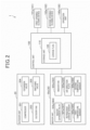
- Fig. 1 is a diagram showing a schematic configuration of a refrigerant circuit of an air conditioning apparatus 1 according to the embodiment of the present invention.
- Fig. 2 is a block diagram schematically showing each part of the air conditioning apparatus 1.
- Fig. 2 shows only an indoor unit 30a as an indoor unit 30, a first opening/closing device 101a as a first opening/closing device 101, and a second opening/closing device 102a as a second opening/closing device 102.
- the air conditioning apparatus 1 includes an outdoor unit 20, and a plurality of indoor units 30a, 30b, 30c.
- the indoor units 30a, 30b, 30c are connected in parallel to the outdoor unit 20 through a liquid-side pipe 11 and a gas-side pipe 12.
- the liquid-side pipe 11 includes liquid-side pipes 13a, 13b, 13c which branch from the liquid-side pipe 11 and are respectively connected to the indoor units 30a, 30b, 30c.
- the gas-side pipe 12 includes gas-side pipes 14a, 14b, 14c which branch from the gas-side pipe 12 and are respectively connected to the indoor units 30a, 30b, 30c.
- the outdoor unit 20, the indoor units 30a, 30b, 30c, the liquid-side pipe 11, and the gas-side pipe 12 constitute a refrigeration cycle.
- the air conditioning apparatus 1 circulates, between the outdoor unit 20 and the indoor units 30a, 30b, 30c, a refrigerant compressed by the outdoor unit 20, thereby air-conditioning a space to be air-conditioned where the indoor units 30a, 30b, 30c are installed.
- the indoor units 30a, 30b, 30c are configured similarly to each other.
- corresponding elements between the indoor units 30a, 30b, 30c are designated with the same reference numeral and distinguished from each other with indexes a, b, c.
- indexes a, b, c may be omitted.
- the outdoor unit 20 includes a compressor 201 which compresses the refrigerant, an outdoor heat exchanger 202 which performs heat exchange of the refrigerant, an outdoor fan 203, an expansion valve 204, and a switching valve 205.
- the compressor 201 sucks the refrigerant from a suction pipe 208, compresses the sucked refrigerant, and discharges the compressed refrigerant.
- the outdoor heat exchanger 202 exchanges heat between the refrigerant and outdoor air in the outdoor unit 20.
- the outdoor heat exchanger 202 functions as a condenser in a cooling operation mode and functions as an evaporator in a heating operation mode.
- the outdoor fan 203 blows air to the outdoor heat exchanger 202.
- the expansion valve 204 decompresses and expands the high-pressure refrigerant.
- the expansion valve 204 has an adjustable opening degree.
- the opening degree of the expansion valve 204 is controlled by a control unit 100.
- the expansion valve 204 may be a valve that has an adjustable opening degree and is capable of blocking the refrigerant.
- the switching valve 205 includes, for example, a four-way valve.
- the switching valve 205 switches the flow of the refrigerant discharged from the compressor 201 and the refrigerant returning to the compressor 201.
- the switching valve 205 switches between the cooling operation mode and the heating operation mode of the air conditioning apparatus 1.
- the indoor unit 30 includes an indoor heat exchanger 301, an indoor fan 302, an indoor expansion valve 304, a first temperature sensor 305, a second temperature sensor 306, and a refrigerant leakage sensor 307.
- the indoor heat exchanger 301 exchanges heat between the refrigerant supplied from the outdoor unit 20 through the liquid-side pipe 11 or the gas-side pipe 12 and indoor air.
- the indoor heat exchanger 301 corresponds to an example of a use-side heat exchanger.
- the indoor fan 302 functions as an air blowing fan that blows air to the indoor heat exchanger 301 to feed air-conditioning air.
- the indoor expansion valve 304 is disposed on the liquid-side pipe 11 between the expansion valve 204 and the indoor heat exchanger 301.
- the indoor expansion valve 304 is disposed on the liquid-side pipe 13 connected to the indoor heat exchanger 301.
- the indoor expansion valve 304 is configured similarly to the expansion valve 204.
- the indoor expansion valve 304 corresponds to an example of a throttle device.
- the liquid-side pipe 13 connected to the indoor heat exchanger 301 is provided with a first temperature sensor 305.
- the first temperature sensor 305 is disposed in a connection part where the liquid-side pipe 13 is connected to the indoor heat exchanger 301.
- the first temperature sensor 305 detects the temperature of the refrigerant and inputs a detection signal to the control unit 100.
- the gas-side pipe 14 connected to the indoor heat exchanger 301 is provided with a second temperature sensor 306.
- the second temperature sensor 306 is disposed in a connection part where the gas-side pipe 14 is connected to the indoor heat exchanger 301.
- the second temperature sensor 306 detects the temperature of the refrigerant and inputs a detection signal to the control unit 100.
- Examples of the refrigerant used in the air conditioning apparatus 1 include various refrigerants.
- refrigerants such as hydrocarbons, ammonia, and R32 are used as so-called CFC substitutes in air conditioning apparatuses.
- the CFC substitutes include a slightly flammable or flammable CFC substitute.
- LFL lower flammability limit
- the refrigerant leakage sensor 307 is disposed near the indoor heat exchanger 301.
- the refrigerant leakage sensor 307 detects a refrigerant concentration and transmits the detected refrigerant concentration as a detection signal to the control unit 100.
- the indoor unit 30 includes an air outlet 310 for blowing out air-conditioning air fed by the indoor fan 302.
- the air outlet 310 is provided with an air direction plate 320 which is capable of opening and closing the air outlet 310.
- the air direction plate 320 turns to open or close the air outlet 310.
- the air direction plate 320 functions as a member that controls a blow-out direction of the air-conditioning air.
- a first opening/closing device 101 and a second opening/closing device 102 which regulate the flow rate of the refrigerant to the indoor unit 30 are disposed on opposite sides of the indoor heat exchanger 301 of the indoor unit 30.
- the first opening/closing device 101 is disposed on the liquid-side pipe 13 connected to the indoor heat exchanger 301.
- the first opening/closing device 101 of the present embodiment includes an on-off valve such as a motor-operated valve or an electromagnetic valve.
- the first opening/closing device 101 is switchable between an open state in which the refrigerant circulates therethrough and a closed state in which the flow of the refrigerant is blocked. Opening and closing of the first opening/closing device 101 are controllable by the control unit 100.
- the first opening/closing device 101 is configured to automatically become the closed state when power fails.
- the first opening/closing device 101 may be a valve settable to a state between the open state and the closed state, or the opening degree of the first opening/closing device 101 may be controlled by the control unit 100.
- the second opening/closing device 102 is disposed on the gas-side pipe 14 connected to the indoor heat exchanger 301.
- the second opening/closing device 102 is configured similarly to the first opening/closing device 101.
- the refrigerant flows in a circulation direction F2.
- the refrigerant flows through the compressor 201, the indoor heat exchanger 301, the indoor expansion valve 304, the expansion valve 204, the outdoor heat exchanger 202, and the switching valve 205 in this order and returns to the suction pipe 208 from the switching valve 205.
- the air conditioning apparatus 1 includes the control unit 100.
- the control unit 100 includes a computer including a processor, such as a CPU or an MPU, and a memory device, such as a ROM or a RAM, and controls each part of the air conditioning apparatus 1.
- An operation unit 100a which includes a remote controller or an operation panel is connected to the control unit 100 through a wire or wirelessly.
- the operation unit 100a is provided with a display unit 100b.
- the display unit 100b is configured to display an operation state of the operation unit 100a and an operating state of the air conditioning apparatus 1.
- the operation unit 100a corresponds to an example of an input unit.
- control unit 100 is connected to the outdoor unit 20, the indoor unit 30, the first opening/closing device 101, and the second opening/closing device 102 through a wire or wirelessly.
- the control unit 100 receives, for example, a detection signal transmitted from the refrigerant leakage sensor 307 and a signal transmitted from each part of the air conditioning apparatus 1 and also transmits a signal to each part of the air conditioning apparatus 1.
- the control unit 100 controls operation of each part in the refrigeration cycle of the air conditioning apparatus 1.
- control unit 100 executes control of the operation of the compressor 201, control of the opening degree and opening and closing of the expansion valve 204 and the indoor expansion valve 304, control of switching of a flow passage of the switching valve 205, and control of the operation and stop of the outdoor fan 203 and the indoor fan 302.
- the control unit 100 operates the expansion valve 204, the indoor expansion valve 304, and the switching valve 205 to switch between the cooling operation mode and the heating operation mode of the air conditioning apparatus 1. Moreover, the control unit 100 executes control of the operation frequency, operation, and stop of the compressor 201 and control of the outdoor fan 203 and the indoor fan 302 according to a target temperature set by an operation on the operation unit 100a to air-condition the space to be air-conditioned according to the target temperature.
- the control unit 100 executes control of opening and closing of the first opening/closing device 101 and the second opening/closing device 102.
- control unit 100 adjusts opening and closing and the opening degree of the air direction plate 320.
- the control unit 100 receives a detection signal of the refrigerant leakage sensor 307 and determines whether there is refrigerant leakage in the indoor unit 30.
- the control unit 100 of the present embodiment acquires the refrigerant concentration in the indoor unit 30 by acquiring the detection signal from the refrigerant leakage sensor 307. Then, the control unit 100 determines whether the acquired refrigerant concentration is higher than a predetermined value. When it is determined that the acquired refrigerant concentration is higher than the predetermined value, the control unit 100 executes an anti-leakage measure operation.
- control unit 100 stops the compressor 201 and brings the first opening/closing device 101 and the second opening/closing device 102 into the closed state. This enables the air conditioning apparatus 1 to suppress refrigerant leakage.
- control unit 100 determines whether the refrigerant concentration determined to be higher than the predetermined value is erroneously detected by the refrigerant leakage sensor 307.
- the control unit 100 when the refrigerant leakage sensor 307 detects a refrigerant concentration higher than the predetermined value, the control unit 100 operates and stops the indoor fan 302 and opens and closes the air direction plate 320 and acquires the refrigerant concentration or a change amount of the refrigerant concentration as occasion arises. Then, the control unit 100 determines whether the detection signal of the refrigerant leakage sensor 307 is generated by erroneous detection from the acquired refrigerant concentration or the required change amount of the refrigerant concentration.
- the control unit 100 brings the first opening/closing device 101 and the second opening/closing device 102 into the open state, resumes the operation of the compressor 201, and returns the air conditioning apparatus 1 to normal operation. That is, when it is determined that the detection signal of the refrigerant leakage sensor 307 is generated by erroneous detection, the control unit 100 causes the air conditioning apparatus 1 to automatically resume the normal operation.
- control unit 100 continues the anti-leakage measure operation and notifies a user, through the operation unit 100a, that there is refrigerant leakage.
- control unit 100 when there is refrigerant leakage, the control unit 100 can promptly suppress the refrigerant leakage. Moreover, when detection of the refrigerant leakage sensor 307 is erroneous detection, the control unit 100 can promptly return the air conditioning apparatus 1 to the normal operation.
- the air conditioning apparatus 1 can reduce temperature changes in the space to be air-conditioned and improve the comfort of the user.
- the control unit 100 further includes a storage unit 110 which stores various pieces of data related to the operation of the air conditioning apparatus 1, such as the operation mode of the air conditioning apparatus 1 and the refrigerant concentration detected by the refrigerant leakage sensor 207.
- the storage unit 110 includes a leakage flag 120 indicating that there is refrigerant leakage.
- the leakage flag 120 is set by the control unit 100 when the control unit 100 determines that there is refrigerant leakage.
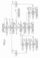
- Fig. 3 is a flowchart showing an operation of the air conditioning apparatus 1. Although Fig. 3 and the following description show a case where one of the refrigerant leakage sensors 307 of the three indoor units 30 included in the air conditioning apparatus 1 transmits a detection signal, the air conditioning apparatus 1 performs an operation similar to the described operation also when two or more of the refrigerant leakage sensors 307 of the indoor units 30 transmit detection signals.
- the control unit 100 acquires a refrigerant concentration detected by the refrigerant leakage sensor 307 at a predetermined frequency and determines whether the acquired refrigerant concentration is higher than the predetermined value (step ST1).
- step ST1 When it is determined that the refrigerant concentration detected by the refrigerant leakage sensor 307 is higher than the predetermined value (step ST1: YES), the control unit 100 causes a predetermined part to execute the anti-leakage measure operation.
- control unit 100 stops the operation of the compressor 201 (step ST2). Moreover, the control unit 100 brings the first opening/closing device 101 and the second opening/closing device 102 into the closed state and operates the indoor fan 302 (step ST3).
- control unit 100 determines whether the leakage flag 120 indicating that there is refrigerant leakage is set (step ST4).
- step ST4 NO
- the control unit 100 again acquires a refrigerant concentration detected by the refrigerant leakage sensor 307 and determines whether the refrigerant concentration has become equal to or lower than the predetermined value by the anti-leakage measure operation (step ST5).
- step ST5 When it is determined that the refrigerant concentration has become equal to or lower than the predetermined value (step ST5: YES), the control unit 100 brings the first opening/closing device 101 and the second opening/closing device 102 into the open state and stops the indoor fan 302 (step ST6).
- control unit 100 again acquires a refrigerant concentration detected by the refrigerant leakage sensor 307 and determines whether the refrigerant concentration has remained unchanged or has decreased (step ST7).
- step ST7 When it is determined that the refrigerant concentration has remained unchanged or has decreased even though the first opening/closing device 101 and the second opening/closing device 102 are in the open state (step ST7: YES), the control unit 100 determines that there is no refrigerant leakage. That is, the control unit 100 determines that the refrigerant concentration determined in step ST1 is erroneously detected by the refrigerant leakage sensor 307 (step ST8).
- step ST7 when it is determined that the refrigerant concentration has increased in step ST7 (step ST7: NO), the control unit 100 turns the air direction plate 320 to close the air outlet 310 and stops the indoor fan 302 (step ST9). Then, in this state, the control unit 100 again acquires a refrigerant concentration detected by the refrigerant leakage sensor 307 and determines whether the refrigerant concentration has remained unchanged or has decreased (step ST10).
- step ST10 When it is determined that the refrigerant concentration has remained unchanged or has decreased (step ST10: YES), the control unit 100 determines that there is no refrigerant leakage. That is, the control unit 100 determines that the refrigerant concentration determined in step ST1 is erroneously detected by the refrigerant leakage sensor 307 (step ST11).
- step ST10 when it is determined that the refrigerant concentration has increased in step ST10 (step ST10: NO), there is a high possibility that there is refrigerant leakage inside the indoor unit 30. Thus, the control unit 100 sets the leakage flag 120 (step ST12).
- control unit 100 brings the first opening/closing device 101 and the second opening/closing device 102 into the closed state, operates the indoor fan 302, and causes the predetermined part to execute the anti-leakage measure operation.
- the control unit 100 again determines whether the leakage flag 120 is set (step ST4) and determines that there is refrigerant leakage (step ST13) when the leakage flag 120 is set (step ST4: YES).
- step ST5 when it is determined in step ST5 that the refrigerant concentration has not become equal to or lower than the predetermined value (step ST5: YES), it is assumed that, for example, a large amount of refrigerant leaks out into the indoor unit 30 or a large amount of smoke or gas is emitted into the space to be air-conditioned.
- control unit 100 turns the air direction plate 320 to close the air outlet 310 and stops the indoor fan 302 (step ST14).
- control unit 100 again acquires a refrigerant concentration detected by the refrigerant leakage sensor 307 and determines whether the refrigerant concentration has remained unchanged or has decreased (step ST15).
- step ST15 When it is determined that the refrigerant concentration has remained unchanged or has decreased (step ST15: YES), the control unit 100 turns the air direction plate 320 to again open the air outlet 310 (step ST16).
- control unit 100 again acquires a refrigerant concentration detected by the refrigerant leakage sensor 307 and determines whether the refrigerant concentration has increased (step ST17). That is, in a state where air from the space to be air-conditioned flows in, the control unit 100 determines whether the refrigerant concentration has increased.
- step ST17 When it is determined that the refrigerant concentration has increased (step ST17: YES), the control unit 100 determines that there is no refrigerant leakage. That is, the control unit 100 determines that the refrigerant concentration determined in step ST1 is erroneously detected by the refrigerant leakage sensor 307, for example, because a large amount of smoke or gas is emitted into the space to be air-conditioned (step ST18).
- step ST17 when it is determined that the refrigerant concentration has not increased (step ST17: NO), the control unit 100 shifts to step ST6 and performs steps ST7 to ST13 described above, thereby determining whether the detection signal of the refrigerant leakage sensor 307 is generated by erroneous detection.
- step ST15 When it is determined that the refrigerant concentration has increased (step ST15: NO), there is a high possibility that there is refrigerant leakage inside the indoor unit 30 because the refrigerant concentration inside the indoor unit 30 has increased in a state where the entry of air from the space to be air-conditioned is prevented. Thus, the control unit 100 sets the leakage flag 120 (step ST19).
- control unit 100 brings the first opening/closing device 101 and the second opening/closing device 102 into the closed state, operates the indoor fan 302, and causes the predetermined part to execute the anti-leakage measure operation.
- the control unit 100 again determines whether the leakage flag 120 is set (step ST4) and determines that there is refrigerant leakage (step ST13) when the leakage flag 120 is set (step ST4: YES).
- the air conditioning apparatus 1 executes the anti-leakage measure operation, and the control unit 100 then determines whether the detection of the refrigerant leakage sensor 307 is erroneous detection.
- control unit 100 brings the first opening/closing device 101 and the second opening/closing device 102 into the open state, resumes the operation of the compressor 201, and returns the air conditioning apparatus 1 to the normal operation.
- control unit 100 continues the anti-leakage measure operation and notifies the user, through the operation unit 100a, that there is refrigerant leakage.
- the air conditioning apparatus 1 includes the outdoor unit 20, the indoor unit 30 including the indoor fan 302, the air outlet 310, and the refrigerant leakage sensor 307 which detects the refrigerant, the liquid-side pipes 11, 13 and the gas-side pipe 12 which connect the outdoor unit 20 and the indoor unit 30, and the first opening/closing device 101 and the second opening/closing device 102 which open and close these pipes.
- the air conditioning apparatus 1 includes the control unit 100 which, when the refrigerant leakage sensor 307 detects a refrigerant concentration higher than the predetermined value, closes the first opening/closing device 101 and the second opening/closing device 102 and determines whether the detection of the refrigerant leakage sensor 307 is erroneous detection.
- the control unit 100 determines whether there is refrigerant leakage in a state where the first opening/closing device 101 and the second opening/closing device 102 are closed.
- the control unit 100 can determine whether detection of the refrigerant leakage sensor 307 is erroneous detection while more reliably suppressing refrigerant leakage.
- the control unit 100 closes the first opening/closing device 101 and the second opening/closing device 102 and drives the indoor fan 302 for a predetermined time.
- the control unit 100 stops the indoor fan 302 and closes the air direction plate 320.
- the control unit 100 opens the air direction plate 320.
- the control unit 100 determines whether detection of the refrigerant leakage sensor 307 is erroneous detection.
- control unit 100 acquires the refrigerant concentration in a case where the air direction plate 320 is open and the refrigerant concentration in a case where the air direction plate 320 is closed and determines whether the detection signal of the refrigerant leakage sensor 307 is generated by erroneous detection.
- control unit 100 can achieve erroneous detection determination for the refrigerant leakage sensor 307 with higher accuracy.
- the control unit 100 closes the first opening/closing device 101 and the second opening/closing device 102 and drives the indoor fan 302 for a predetermined time.
- the control unit 100 opens the first opening/closing device 101 and the second opening/closing device 102 and stops the indoor fan 302.
- the control unit 100 determines that detection of the refrigerant leakage sensor 307 is erroneous detection.
- control unit 100 determines that the detection signal of the refrigerant leakage sensor 307 is generated by erroneous detection when determining that the refrigerant concentration has temporarily increased due to, for example, spray gas or cigarette smoke.
- control unit 100 determines that there is refrigerant leakage by setting the leakage flag 120.
- control unit 100 determines that there is refrigerant leakage on the erroneous detection determination process.
- the control unit 100 when it is determined that the detection is not erroneous detection, that is, there is refrigerant leakage, the control unit 100 continues the anti-leakage measure operation and notifies the user, through the operation unit 100a, that there is refrigerant leakage.
- the present invention is not limited thereto. While the erroneous detection determination process is being performed, the control unit 100 may display, on an element provided with a display unit, such as the operation unit 100a, that the erroneous detection determination is being performed to notify the user of the erroneous detection determination.
- the air conditioning apparatus according to the present invention is suitably usable as an air conditioning apparatus capable of appropriately determining whether there is refrigerant leakage.
Landscapes
- Engineering & Computer Science (AREA)
- Chemical & Material Sciences (AREA)
- Combustion & Propulsion (AREA)
- Mechanical Engineering (AREA)
- General Engineering & Computer Science (AREA)
- Health & Medical Sciences (AREA)
- Biomedical Technology (AREA)
- Air Conditioning Control Device (AREA)
Description
- The present invention relates to an air conditioning apparatus.
- Conventionally known air conditioning apparatuses include an outdoor unit, an indoor unit, and a refrigerant pipe which constitute a refrigeration cycle, and the indoor unit is provided with a refrigerant leakage sensor which detects leakage of a refrigerant flowing through the refrigeration cycle, the leakage being caused by, for example, breakage of the refrigerant pipe.
- An air conditioning apparatus known as such an air conditioning apparatus is capable of determining whether detection of the refrigerant leakage sensor is erroneous detection to prevent the refrigerant leakage sensor from erroneously detecting, as refrigerant leakage, an object other than the refrigerant, such as smoke generated in a space where the indoor unit is installed (e.g., refer to
Japanese Patent Laid-Open No. 2016-090175 - However, in the conventional air conditioning apparatus, after the refrigerant leakage sensor detects the refrigerant, it is determined whether the detection of the refrigeration leakage sensor is erroneous detection without closing the refrigerant pipe through which the refrigerant flows. Thus, when the detection of the refrigerant leakage sensor is not erroneous detection, the refrigerant may further leak during the determination as to whether the detection of the refrigerant leakage sensor is erroneous detection.
- It is an object of the present invention to provide an air conditioning apparatus capable of determining whether detection of the refrigerant leakage sensor is erroneous detection while more reliably suppressing refrigerant leakage.
-
EP 3 584 521 A1 describes a refrigeration apparatus that includes a compressor; a heat source-side expansion valve to be controlled to have a minimum opening degree and brought into a closed state in which the heat source-side expansion valve maximizes prevention of a flow of a refrigerant toward a usage-side refrigerant circuit; a fusible plug; a controller; and a refrigerant leak sensor configured to detect a refrigerant leak at the usage-side refrigerant circuit. An erroneous detection determination unit determines whether the refrigerant leak sensor erroneously detects a refrigerant leak when the refrigerant leak sensor detects the refrigerant leak. - The present invention provides an air conditioning apparatus as defined in appended
claim 1. The air conditioning apparatus includes: an outdoor unit; an indoor unit including an air blowing fan, an air outlet for blowing out air fed by the air blowing fan, an air direction plate capable of opening and closing the air outlet, and a refrigerant leakage sensor configured to detect a refrigerant; a refrigerant pipe connecting the outdoor unit and the indoor unit; an opening/closing device configured to open and close the refrigerant pipe; and a control unit configured to close the opening/closing device and drive the air blowing fan for a predetermined time when the refrigerant leakage sensor detects a refrigerant concentration higher than a predetermined value, then stop the air blowing fan and close the air direction plate when the refrigerant leakage sensor detects a refrigerant concentration higher than the predetermined value, then open the air direction plate when a refrigerant concentration detected by the refrigerant leakage sensor remains substantially equal to or decreases from the concentration previously detected, and then determine that detection of the refrigerant leakage sensor is erroneous detection when a refrigerant concentration detected by the refrigerant leakage sensor becomes higher than the concentration previously detected. - With this configuration, the control unit determines whether there is refrigerant leakage in a state where the opening/closing device configured to open and close the refrigerant pipe is closed. Thus, the control unit can determine whether detection of the refrigerant leakage sensor is erroneous detection while more reliably suppressing refrigerant leakage.
- According to the present invention, it is possible to determine whether detection of the refrigerant leakage sensor is erroneous detection while more reliably suppressing refrigerant leakage.
-
-
Fig. 1 is a diagram showing a schematic configuration of a refrigerant circuit of an air conditioning apparatus according to an embodiment of the present invention; -
Fig. 2 is a block diagram schematically showing each part of the air conditioning apparatus; and -
Fig. 3 is a flowchart showing an operation of the air conditioning apparatus. - Among others, the air conditioning apparatus of the present invention includes: an outdoor unit; an indoor unit including an air blowing fan, an air outlet for blowing out air fed by the air blowing fan, an air direction plate capable of opening and closing the air outlet, and a refrigerant leakage sensor configured to detect a refrigerant; a refrigerant pipe connecting the outdoor unit and the indoor unit; an opening/closing device configured to open and close the refrigerant pipe; and a control unit.
- The control unit is configured to close the opening/closing device and drive the air blowing fan for a predetermined time when the refrigerant leakage sensor detects a refrigerant concentration higher than the predetermined value, then stop the air blowing fan and close the air direction plate when the refrigerant leakage sensor detects a refrigerant concentration higher than the predetermined value, then open the air direction plate when a refrigerant concentration detected by the refrigerant leakage sensor remains substantially equal to or decreases from the concentration previously detected, and then determine that detection of the refrigerant leakage sensor is erroneous detection when a refrigerant concentration detected by the refrigerant leakage sensor becomes higher than the concentration previously detected.
- With this configuration, the control unit determines whether there is refrigerant leakage in a state where the opening/closing device configured to open and close the refrigerant pipe is closed. Thus, the control unit can determine whether detection of the refrigerant leakage sensor is erroneous detection while more reliably suppressing refrigerant leakage. Moreover, the control unit acquires the refrigerant concentration in a case where the air direction plate is open and the refrigerant concentration in a case where the air direction plate is closed and determines whether a detection signal of the refrigerant leakage sensor is generated by erroneous detection.
- Thus, for example, even in the space to be air-conditioned constantly filled with a large amount of smoke or gas, such as a smoking area, the control unit can achieve erroneous detection determination for the refrigerant leakage sensor with higher accuracy.
- In an embodiment, the control unit closes the opening/closing device and drives the air blowing fan for a predetermined time when the refrigerant leakage sensor detects a refrigerant concentration higher than the predetermined value, then opens the opening/closing device and stops the air blowing fan when the refrigerant leakage sensor detects a refrigerant concentration equal to or lower than the predetermined value, and then determines that detection of the refrigerant leakage sensor is erroneous detection when a refrigerant concentration detected by the refrigerant leakage sensor remains substantially equal to or decreases from the concentration previously detected.
- With this configuration, when, for example, smoke temporarily builds up inside the indoor unit, the air conditioning apparatus feeds the smoke out by using the air blowing fan to remove the smoke, thereby preventing erroneous detection.
- This enables the control unit to determine that the detection signal of the refrigerant leakage sensor is generated by erroneous detection when determining that the refrigerant concentration has temporarily increased due to, for example, spray gas or cigarette smoke.
- Hereinbelow, an embodiment of the present invention will be described with reference to the drawings.
-
Fig. 1 is a diagram showing a schematic configuration of a refrigerant circuit of anair conditioning apparatus 1 according to the embodiment of the present invention.Fig. 2 is a block diagram schematically showing each part of theair conditioning apparatus 1. For convenience of description,Fig. 2 shows only anindoor unit 30a as anindoor unit 30, a first opening/closing device 101a as a first opening/closing device 101, and a second opening/closing device 102a as a second opening/closing device 102. - The
air conditioning apparatus 1 includes anoutdoor unit 20, and a plurality ofindoor units indoor units outdoor unit 20 through a liquid-side pipe 11 and a gas-side pipe 12. The liquid-side pipe 11 includes liquid-side pipes side pipe 11 and are respectively connected to theindoor units side pipe 12 includes gas-side pipes side pipe 12 and are respectively connected to theindoor units - The
outdoor unit 20, theindoor units side pipe 11, and the gas-side pipe 12 constitute a refrigeration cycle. - The
air conditioning apparatus 1 circulates, between theoutdoor unit 20 and theindoor units outdoor unit 20, thereby air-conditioning a space to be air-conditioned where theindoor units - The
indoor units indoor units - The
outdoor unit 20 includes acompressor 201 which compresses the refrigerant, anoutdoor heat exchanger 202 which performs heat exchange of the refrigerant, anoutdoor fan 203, anexpansion valve 204, and aswitching valve 205. - The
compressor 201 sucks the refrigerant from asuction pipe 208, compresses the sucked refrigerant, and discharges the compressed refrigerant. - The
outdoor heat exchanger 202 exchanges heat between the refrigerant and outdoor air in theoutdoor unit 20. Theoutdoor heat exchanger 202 functions as a condenser in a cooling operation mode and functions as an evaporator in a heating operation mode. - The
outdoor fan 203 blows air to theoutdoor heat exchanger 202. - The
expansion valve 204 decompresses and expands the high-pressure refrigerant. Theexpansion valve 204 has an adjustable opening degree. The opening degree of theexpansion valve 204 is controlled by acontrol unit 100. Theexpansion valve 204 may be a valve that has an adjustable opening degree and is capable of blocking the refrigerant. - The
switching valve 205 includes, for example, a four-way valve. Theswitching valve 205 switches the flow of the refrigerant discharged from thecompressor 201 and the refrigerant returning to thecompressor 201. Theswitching valve 205 switches between the cooling operation mode and the heating operation mode of theair conditioning apparatus 1. - The
indoor unit 30 includes an indoor heat exchanger 301, anindoor fan 302, anindoor expansion valve 304, a first temperature sensor 305, a second temperature sensor 306, and a refrigerant leakage sensor 307. - The indoor heat exchanger 301 exchanges heat between the refrigerant supplied from the
outdoor unit 20 through the liquid-side pipe 11 or the gas-side pipe 12 and indoor air. The indoor heat exchanger 301 corresponds to an example of a use-side heat exchanger. - The
indoor fan 302 functions as an air blowing fan that blows air to the indoor heat exchanger 301 to feed air-conditioning air. - The
indoor expansion valve 304 is disposed on the liquid-side pipe 11 between theexpansion valve 204 and the indoor heat exchanger 301. In the present embodiment, theindoor expansion valve 304 is disposed on the liquid-side pipe 13 connected to the indoor heat exchanger 301. Theindoor expansion valve 304 is configured similarly to theexpansion valve 204. Theindoor expansion valve 304 corresponds to an example of a throttle device. - The liquid-side pipe 13 connected to the indoor heat exchanger 301 is provided with a first temperature sensor 305. In the present embodiment, the first temperature sensor 305 is disposed in a connection part where the liquid-side pipe 13 is connected to the indoor heat exchanger 301. The first temperature sensor 305 detects the temperature of the refrigerant and inputs a detection signal to the
control unit 100. - The gas-side pipe 14 connected to the indoor heat exchanger 301 is provided with a second temperature sensor 306. In the present embodiment, the second temperature sensor 306 is disposed in a connection part where the gas-side pipe 14 is connected to the indoor heat exchanger 301. The second temperature sensor 306 detects the temperature of the refrigerant and inputs a detection signal to the
control unit 100. - Examples of the refrigerant used in the
air conditioning apparatus 1 include various refrigerants. In recent years, refrigerants such as hydrocarbons, ammonia, and R32 are used as so-called CFC substitutes in air conditioning apparatuses. The CFC substitutes include a slightly flammable or flammable CFC substitute. When the slightly flammable or flammable refrigerant leaks, it is required that the amount of refrigerant leakage be reduced so that the refrigerant concentration in the space to be air-conditioned of theindoor unit 30 does not reach a lower flammability limit (LFL). In particular, reducing the amount of refrigerant leakage from the space to be air-conditioned or theindoor unit 30 installed near the space to be air-conditioned is desired. - The refrigerant leakage sensor 307 is disposed near the indoor heat exchanger 301. The refrigerant leakage sensor 307 detects a refrigerant concentration and transmits the detected refrigerant concentration as a detection signal to the
control unit 100. - The
indoor unit 30 includes an air outlet 310 for blowing out air-conditioning air fed by theindoor fan 302. The air outlet 310 is provided with anair direction plate 320 which is capable of opening and closing the air outlet 310. Theair direction plate 320 turns to open or close the air outlet 310. Moreover, theair direction plate 320 functions as a member that controls a blow-out direction of the air-conditioning air. - A first opening/
closing device 101 and a second opening/closing device 102 which regulate the flow rate of the refrigerant to theindoor unit 30 are disposed on opposite sides of the indoor heat exchanger 301 of theindoor unit 30. - The first opening/
closing device 101 is disposed on the liquid-side pipe 13 connected to the indoor heat exchanger 301. The first opening/closing device 101 of the present embodiment includes an on-off valve such as a motor-operated valve or an electromagnetic valve. The first opening/closing device 101 is switchable between an open state in which the refrigerant circulates therethrough and a closed state in which the flow of the refrigerant is blocked. Opening and closing of the first opening/closing device 101 are controllable by thecontrol unit 100. The first opening/closing device 101 is configured to automatically become the closed state when power fails. - The first opening/
closing device 101 may be a valve settable to a state between the open state and the closed state, or the opening degree of the first opening/closing device 101 may be controlled by thecontrol unit 100. - The second opening/
closing device 102 is disposed on the gas-side pipe 14 connected to the indoor heat exchanger 301. The second opening/closing device 102 is configured similarly to the first opening/closing device 101. - In the cooling operation mode of the
air conditioning apparatus 1, the refrigerant flows in a circulation direction F1. The refrigerant flows through thecompressor 201, theoutdoor heat exchanger 202, theexpansion valve 204, theindoor expansion valve 304, the indoor heat exchanger 301, and the switchingvalve 205 in this order and returns to thesuction pipe 208 from the switchingvalve 205. - On the other hand, in the heating operation mode of the
air conditioning apparatus 1, the refrigerant flows in a circulation direction F2. The refrigerant flows through thecompressor 201, the indoor heat exchanger 301, theindoor expansion valve 304, theexpansion valve 204, theoutdoor heat exchanger 202, and the switchingvalve 205 in this order and returns to thesuction pipe 208 from the switchingvalve 205. - As described above, the
air conditioning apparatus 1 includes thecontrol unit 100. Thecontrol unit 100 includes a computer including a processor, such as a CPU or an MPU, and a memory device, such as a ROM or a RAM, and controls each part of theair conditioning apparatus 1. - An
operation unit 100a which includes a remote controller or an operation panel is connected to thecontrol unit 100 through a wire or wirelessly. Theoperation unit 100a is provided with adisplay unit 100b. Thedisplay unit 100b is configured to display an operation state of theoperation unit 100a and an operating state of theair conditioning apparatus 1. Theoperation unit 100a corresponds to an example of an input unit. - As shown in
Fig. 2 , thecontrol unit 100 is connected to theoutdoor unit 20, theindoor unit 30, the first opening/closing device 101, and the second opening/closing device 102 through a wire or wirelessly. Thecontrol unit 100 receives, for example, a detection signal transmitted from the refrigerant leakage sensor 307 and a signal transmitted from each part of theair conditioning apparatus 1 and also transmits a signal to each part of theair conditioning apparatus 1. - The
control unit 100 controls operation of each part in the refrigeration cycle of theair conditioning apparatus 1. - Specifically, the
control unit 100 executes control of the operation of thecompressor 201, control of the opening degree and opening and closing of theexpansion valve 204 and theindoor expansion valve 304, control of switching of a flow passage of the switchingvalve 205, and control of the operation and stop of theoutdoor fan 203 and theindoor fan 302. - The
control unit 100 operates theexpansion valve 204, theindoor expansion valve 304, and the switchingvalve 205 to switch between the cooling operation mode and the heating operation mode of theair conditioning apparatus 1. Moreover, thecontrol unit 100 executes control of the operation frequency, operation, and stop of thecompressor 201 and control of theoutdoor fan 203 and theindoor fan 302 according to a target temperature set by an operation on theoperation unit 100a to air-condition the space to be air-conditioned according to the target temperature. - The
control unit 100 executes control of opening and closing of the first opening/closing device 101 and the second opening/closing device 102. - Moreover, the
control unit 100 adjusts opening and closing and the opening degree of theair direction plate 320. - The
control unit 100 receives a detection signal of the refrigerant leakage sensor 307 and determines whether there is refrigerant leakage in theindoor unit 30. - The
control unit 100 of the present embodiment acquires the refrigerant concentration in theindoor unit 30 by acquiring the detection signal from the refrigerant leakage sensor 307. Then, thecontrol unit 100 determines whether the acquired refrigerant concentration is higher than a predetermined value. When it is determined that the acquired refrigerant concentration is higher than the predetermined value, thecontrol unit 100 executes an anti-leakage measure operation. - Specifically, the
control unit 100 stops thecompressor 201 and brings the first opening/closing device 101 and the second opening/closing device 102 into the closed state. This enables theair conditioning apparatus 1 to suppress refrigerant leakage. - The refrigerant leakage sensor 307 may erroneously detect, as the refrigerant, for example, cigarette smoke or spray gas that is emitted into the space to be air-conditioned and taken into the
indoor unit 30 by the operation of theindoor fan 302. - Thus, after the execution of the anti-leakage measure operation, the
control unit 100 determines whether the refrigerant concentration determined to be higher than the predetermined value is erroneously detected by the refrigerant leakage sensor 307. - Specifically, when the refrigerant leakage sensor 307 detects a refrigerant concentration higher than the predetermined value, the
control unit 100 operates and stops theindoor fan 302 and opens and closes theair direction plate 320 and acquires the refrigerant concentration or a change amount of the refrigerant concentration as occasion arises. Then, thecontrol unit 100 determines whether the detection signal of the refrigerant leakage sensor 307 is generated by erroneous detection from the acquired refrigerant concentration or the required change amount of the refrigerant concentration. - When it is determined that the detection is erroneous detection, the
control unit 100 brings the first opening/closing device 101 and the second opening/closing device 102 into the open state, resumes the operation of thecompressor 201, and returns theair conditioning apparatus 1 to normal operation. That is, when it is determined that the detection signal of the refrigerant leakage sensor 307 is generated by erroneous detection, thecontrol unit 100 causes theair conditioning apparatus 1 to automatically resume the normal operation. - On the other hand, when it is determined that the detection is not erroneous detection, that is, there is refrigerant leakage, the
control unit 100 continues the anti-leakage measure operation and notifies a user, through theoperation unit 100a, that there is refrigerant leakage. - With this configuration, when there is refrigerant leakage, the
control unit 100 can promptly suppress the refrigerant leakage. Moreover, when detection of the refrigerant leakage sensor 307 is erroneous detection, thecontrol unit 100 can promptly return theair conditioning apparatus 1 to the normal operation. - Thus, the
air conditioning apparatus 1 can reduce temperature changes in the space to be air-conditioned and improve the comfort of the user. - The
control unit 100 further includes astorage unit 110 which stores various pieces of data related to the operation of theair conditioning apparatus 1, such as the operation mode of theair conditioning apparatus 1 and the refrigerant concentration detected by the refrigerant leakage sensor 207. - The
storage unit 110 includes aleakage flag 120 indicating that there is refrigerant leakage. Theleakage flag 120 is set by thecontrol unit 100 when thecontrol unit 100 determines that there is refrigerant leakage. - Next, an erroneous detection determination process for determining whether the detection signal of the refrigerant leakage sensor 307 is generated by erroneous detection, the erroneous detection determination process being performed by the
control unit 100 of theair conditioning apparatus 1, will be described with reference toFig. 3 . -
Fig. 3 is a flowchart showing an operation of theair conditioning apparatus 1. AlthoughFig. 3 and the following description show a case where one of the refrigerant leakage sensors 307 of the threeindoor units 30 included in theair conditioning apparatus 1 transmits a detection signal, theair conditioning apparatus 1 performs an operation similar to the described operation also when two or more of the refrigerant leakage sensors 307 of theindoor units 30 transmit detection signals. - When the
air conditioning apparatus 1 is in operation, thecontrol unit 100 acquires a refrigerant concentration detected by the refrigerant leakage sensor 307 at a predetermined frequency and determines whether the acquired refrigerant concentration is higher than the predetermined value (step ST1). - When it is determined that the refrigerant concentration detected by the refrigerant leakage sensor 307 is higher than the predetermined value (step ST1: YES), the
control unit 100 causes a predetermined part to execute the anti-leakage measure operation. - Specifically, the
control unit 100 stops the operation of the compressor 201 (step ST2). Moreover, thecontrol unit 100 brings the first opening/closing device 101 and the second opening/closing device 102 into the closed state and operates the indoor fan 302 (step ST3). - This blocks the flow of the refrigerant and enables the
air conditioning apparatus 1 to suppress refrigerant leakage. Furthermore, when there is leaked refrigerant inside theindoor unit 30, theair conditioning apparatus 1 can release the leaked refrigerant inside theindoor unit 30 to the space to be air-conditioned by operating theindoor fan 302. - Next, the
control unit 100 determines whether theleakage flag 120 indicating that there is refrigerant leakage is set (step ST4). - When the
leakage flag 120 is not set (step ST4: NO), thecontrol unit 100 again acquires a refrigerant concentration detected by the refrigerant leakage sensor 307 and determines whether the refrigerant concentration has become equal to or lower than the predetermined value by the anti-leakage measure operation (step ST5). - When it is determined that the refrigerant concentration has become equal to or lower than the predetermined value (step ST5: YES), the
control unit 100 brings the first opening/closing device 101 and the second opening/closing device 102 into the open state and stops the indoor fan 302 (step ST6). - Then, in this state, the
control unit 100 again acquires a refrigerant concentration detected by the refrigerant leakage sensor 307 and determines whether the refrigerant concentration has remained unchanged or has decreased (step ST7). - When it is determined that the refrigerant concentration has remained unchanged or has decreased even though the first opening/
closing device 101 and the second opening/closing device 102 are in the open state (step ST7: YES), thecontrol unit 100 determines that there is no refrigerant leakage. That is, thecontrol unit 100 determines that the refrigerant concentration determined in step ST1 is erroneously detected by the refrigerant leakage sensor 307 (step ST8). - On the other hand, when it is determined that the refrigerant concentration has increased in step ST7 (step ST7: NO), the
control unit 100 turns theair direction plate 320 to close the air outlet 310 and stops the indoor fan 302 (step ST9). Then, in this state, thecontrol unit 100 again acquires a refrigerant concentration detected by the refrigerant leakage sensor 307 and determines whether the refrigerant concentration has remained unchanged or has decreased (step ST10). - This prevents smoke or gas emitted into the space to be air-conditioned from entering the inside of the
indoor unit 30 and enables the refrigerant leakage sensor 307 to detect the refrigerant concentration inside theindoor unit 30 with higher accuracy. - When it is determined that the refrigerant concentration has remained unchanged or has decreased (step ST10: YES), the
control unit 100 determines that there is no refrigerant leakage. That is, thecontrol unit 100 determines that the refrigerant concentration determined in step ST1 is erroneously detected by the refrigerant leakage sensor 307 (step ST11). - On the other hand, when it is determined that the refrigerant concentration has increased in step ST10 (step ST10: NO), there is a high possibility that there is refrigerant leakage inside the
indoor unit 30. Thus, thecontrol unit 100 sets the leakage flag 120 (step ST12). - Then, the
control unit 100 brings the first opening/closing device 101 and the second opening/closing device 102 into the closed state, operates theindoor fan 302, and causes the predetermined part to execute the anti-leakage measure operation. Thecontrol unit 100 again determines whether theleakage flag 120 is set (step ST4) and determines that there is refrigerant leakage (step ST13) when theleakage flag 120 is set (step ST4: YES). - On the other hand, when it is determined in step ST5 that the refrigerant concentration has not become equal to or lower than the predetermined value (step ST5: YES), it is assumed that, for example, a large amount of refrigerant leaks out into the
indoor unit 30 or a large amount of smoke or gas is emitted into the space to be air-conditioned. - Thus, the
control unit 100 turns theair direction plate 320 to close the air outlet 310 and stops the indoor fan 302 (step ST14). - This prevents air from the space to be air-conditioned from flowing into the
indoor unit 30. That is, even if there is smoke or gas emitted into the space to be air-conditioned, the entry of the smoke or gas into theindoor unit 30 is prevented. - Then, in this state, the
control unit 100 again acquires a refrigerant concentration detected by the refrigerant leakage sensor 307 and determines whether the refrigerant concentration has remained unchanged or has decreased (step ST15). - When it is determined that the refrigerant concentration has remained unchanged or has decreased (step ST15: YES), the
control unit 100 turns theair direction plate 320 to again open the air outlet 310 (step ST16). - Then, in this state, the
control unit 100 again acquires a refrigerant concentration detected by the refrigerant leakage sensor 307 and determines whether the refrigerant concentration has increased (step ST17). That is, in a state where air from the space to be air-conditioned flows in, thecontrol unit 100 determines whether the refrigerant concentration has increased. - When it is determined that the refrigerant concentration has increased (step ST17: YES), the
control unit 100 determines that there is no refrigerant leakage. That is, thecontrol unit 100 determines that the refrigerant concentration determined in step ST1 is erroneously detected by the refrigerant leakage sensor 307, for example, because a large amount of smoke or gas is emitted into the space to be air-conditioned (step ST18). - On the other hand, when it is determined that the refrigerant concentration has not increased (step ST17: NO), the
control unit 100 shifts to step ST6 and performs steps ST7 to ST13 described above, thereby determining whether the detection signal of the refrigerant leakage sensor 307 is generated by erroneous detection. - When it is determined that the refrigerant concentration has increased (step ST15: NO), there is a high possibility that there is refrigerant leakage inside the
indoor unit 30 because the refrigerant concentration inside theindoor unit 30 has increased in a state where the entry of air from the space to be air-conditioned is prevented. Thus, thecontrol unit 100 sets the leakage flag 120 (step ST19). - Then, the
control unit 100 brings the first opening/closing device 101 and the second opening/closing device 102 into the closed state, operates theindoor fan 302, and causes the predetermined part to execute the anti-leakage measure operation. Thecontrol unit 100 again determines whether theleakage flag 120 is set (step ST4) and determines that there is refrigerant leakage (step ST13) when theleakage flag 120 is set (step ST4: YES). - In this manner, when the refrigerant leakage sensor 307 detects a refrigerant concentration higher than the predetermined value, the
air conditioning apparatus 1 executes the anti-leakage measure operation, and thecontrol unit 100 then determines whether the detection of the refrigerant leakage sensor 307 is erroneous detection. - Then, when it is determined that the detection is erroneous detection, the
control unit 100 brings the first opening/closing device 101 and the second opening/closing device 102 into the open state, resumes the operation of thecompressor 201, and returns theair conditioning apparatus 1 to the normal operation. - On the other hand, when it is determined that the detection is not erroneous detection, that is, there is refrigerant leakage, the
control unit 100 continues the anti-leakage measure operation and notifies the user, through theoperation unit 100a, that there is refrigerant leakage. - As described above, according to the present embodiment, the
air conditioning apparatus 1 includes theoutdoor unit 20, theindoor unit 30 including theindoor fan 302, the air outlet 310, and the refrigerant leakage sensor 307 which detects the refrigerant, the liquid-side pipes 11, 13 and the gas-side pipe 12 which connect theoutdoor unit 20 and theindoor unit 30, and the first opening/closing device 101 and the second opening/closing device 102 which open and close these pipes. Theair conditioning apparatus 1 includes thecontrol unit 100 which, when the refrigerant leakage sensor 307 detects a refrigerant concentration higher than the predetermined value, closes the first opening/closing device 101 and the second opening/closing device 102 and determines whether the detection of the refrigerant leakage sensor 307 is erroneous detection. - With this configuration, the
control unit 100 determines whether there is refrigerant leakage in a state where the first opening/closing device 101 and the second opening/closing device 102 are closed. Thus, thecontrol unit 100 can determine whether detection of the refrigerant leakage sensor 307 is erroneous detection while more reliably suppressing refrigerant leakage. - According to the present embodiment, when the refrigerant leakage sensor 307 detects a refrigerant concentration higher than the predetermined value, the
control unit 100 closes the first opening/closing device 101 and the second opening/closing device 102 and drives theindoor fan 302 for a predetermined time. - Then, when the refrigerant leakage sensor 307 detects a refrigerant concentration higher than the predetermined value, the
control unit 100 stops theindoor fan 302 and closes theair direction plate 320. - Then, when the refrigerant concentration detected by the refrigerant leakage sensor 307 remains substantially equal to or decreases from the concentration previously detected, the
control unit 100 opens theair direction plate 320. - Then, when the refrigerant concentration detected by the refrigerant leakage sensor 307 becomes higher than the concentration previously detected, the
control unit 100 determines whether detection of the refrigerant leakage sensor 307 is erroneous detection. - With this configuration, the
control unit 100 acquires the refrigerant concentration in a case where theair direction plate 320 is open and the refrigerant concentration in a case where theair direction plate 320 is closed and determines whether the detection signal of the refrigerant leakage sensor 307 is generated by erroneous detection. - Thus, for example, even in the space to be air-conditioned constantly filled with a large amount of smoke or gas, such as a smoking area, the
control unit 100 can achieve erroneous detection determination for the refrigerant leakage sensor 307 with higher accuracy. - According to the present embodiment, when the refrigerant leakage sensor 307 detects a refrigerant concentration higher than the predetermined value, the
control unit 100 closes the first opening/closing device 101 and the second opening/closing device 102 and drives theindoor fan 302 for a predetermined time. - Then, when the refrigerant leakage sensor 307 detects a refrigerant concentration equal to or lower than the predetermined value, the
control unit 100 opens the first opening/closing device 101 and the second opening/closing device 102 and stops theindoor fan 302. - Then, when a refrigerant concentration detected by the refrigerant leakage sensor 307 remains substantially equal to or decreases from the concentration previously detected, the
control unit 100 determines that detection of the refrigerant leakage sensor 307 is erroneous detection. - This enables the
control unit 100 to determine that the detection signal of the refrigerant leakage sensor 307 is generated by erroneous detection when determining that the refrigerant concentration has temporarily increased due to, for example, spray gas or cigarette smoke. - According to the present embodiment, the
control unit 100 determines that there is refrigerant leakage by setting theleakage flag 120. - This enables the
control unit 100 to determine that there is refrigerant leakage on the erroneous detection determination process. - In the above embodiment, when it is determined that the detection is not erroneous detection, that is, there is refrigerant leakage, the
control unit 100 continues the anti-leakage measure operation and notifies the user, through theoperation unit 100a, that there is refrigerant leakage. However, the present invention is not limited thereto. While the erroneous detection determination process is being performed, thecontrol unit 100 may display, on an element provided with a display unit, such as theoperation unit 100a, that the erroneous detection determination is being performed to notify the user of the erroneous detection determination. - As described above, the air conditioning apparatus according to the present invention is suitably usable as an air conditioning apparatus capable of appropriately determining whether there is refrigerant leakage.
-
- 1
- air conditioning apparatus
- 11
- liquid-side pipe (refrigerant pipe)
- 12
- gas-side pipe (refrigerant pipe)
- 13
- liquid-side pipe (refrigerant pipe)
- 20
- outdoor unit
- 30
- indoor unit
- 100
- control unit
- 101
- first opening/closing device
- 102
- second opening/closing device
- 110
- storage unit
- 120
- leakage flag
- 201
- compressor
- 302
- indoor fan (air blowing fan)
- 307
- refrigerant leakage sensor
- 310
- air outlet
- 320
- air direction plate
Claims (2)
- An air conditioning apparatus (1) comprising:an outdoor unit (20);an indoor unit (30) including an air blowing fan (302), an air outlet (310) for blowing out air fed by the air blowing fan (302), and a refrigerant leakage sensor (307) configured to detect a refrigerant;a refrigerant pipe (11, 12, 13) connecting the outdoor unit (20) and the indoor unit (30);an opening/closing device (101, 102) configured to open and close the refrigerant pipe, characterized in thatthe indoor unit (30) includes an air direction plate (320) capable of opening and closing the air outlet (310), and in thatthe air conditioning apparatus (1) comprises a control unit (100) configured to close the opening/closing device (101, 102) and drive the air blowing fan (302) for a predetermined time when the refrigerant leakage sensor (307) detects a refrigerant concentration higher than a predetermined value,then stop the air blowing fan (302) and close the air direction plate (320) when the refrigerant leakage sensor (307) detects a refrigerant concentration higher than the predetermined value,then open the air direction plate when a refrigerant concentration detected by the refrigerant leakage sensor (307) remains substantially equal to or decreases from the concentration previously detected, andthen determine that detection of the refrigerant leakage sensor (307) is erroneous detection when a refrigerant concentration detected by the refrigerant leakage sensor (307) becomes higher than the concentration previously detected.
- The air conditioning apparatus (1) according to claim 1, whereinafter the control unit (100) closes the opening/closing device (101, 102) and drives the air blowing fan (302) for the predetermined time,the control unit (100) is configured to open the opening/closing device (101, 102) and stop the air blowing fan (302) when the refrigerant leakage sensor (307) detects a refrigerant concentration equal to or lower than the predetermined value, andthen determine that detection of the refrigerant leakage sensor (307) is erroneous detection when a refrigerant concentration detected by the refrigerant leakage sensor (307) remains substantially equal to or decreases from the concentration previously detected.
Applications Claiming Priority (1)
| Application Number | Priority Date | Filing Date | Title |
|---|---|---|---|
| JP2020026401A JP2021131182A (en) | 2020-02-19 | 2020-02-19 | Air conditioner |
Publications (3)
| Publication Number | Publication Date |
|---|---|
| EP3869113A1 EP3869113A1 (en) | 2021-08-25 |
| EP3869113C0 EP3869113C0 (en) | 2024-10-09 |
| EP3869113B1 true EP3869113B1 (en) | 2024-10-09 |
Family
ID=74285364
Family Applications (1)
| Application Number | Title | Priority Date | Filing Date |
|---|---|---|---|
| EP21153687.5A Active EP3869113B1 (en) | 2020-02-19 | 2021-01-27 | Air conditioning apparatus |
Country Status (2)
| Country | Link |
|---|---|
| EP (1) | EP3869113B1 (en) |
| JP (1) | JP2021131182A (en) |
Families Citing this family (11)
| Publication number | Priority date | Publication date | Assignee | Title |
|---|---|---|---|---|
| US11231198B2 (en) | 2019-09-05 | 2022-01-25 | Trane International Inc. | Systems and methods for refrigerant leak detection in a climate control system |
| US12410926B2 (en) | 2021-10-05 | 2025-09-09 | Carrier Corporation | Frost remidiation and frost sensor |
| US12487008B2 (en) | 2022-01-14 | 2025-12-02 | Trane International Inc. | Method of commissioning an HVAC system |
| CN114754463B (en) * | 2022-03-17 | 2024-06-07 | 青岛海尔空调电子有限公司 | Refrigerant leakage control method and device and multi-split air conditioner |
| US12117191B2 (en) | 2022-06-24 | 2024-10-15 | Trane International Inc. | Climate control system with improved leak detector |
| JP2024052431A (en) * | 2022-09-30 | 2024-04-11 | ダイキン工業株式会社 | Refrigerant leak inspection system and refrigerant leak inspection method |
| CN115751607B (en) * | 2022-11-30 | 2024-11-19 | 珠海格力电器股份有限公司 | Detection method and device for air conditioner connecting pipe, air conditioner and storage medium |
| JP2025079381A (en) * | 2023-11-10 | 2025-05-22 | パナソニックIpマネジメント株式会社 | Air conditioners |
| JP2025148005A (en) * | 2024-03-25 | 2025-10-07 | ダイキン工業株式会社 | Refrigeration equipment |
| CN119063146B (en) * | 2024-09-30 | 2026-02-06 | 奥克斯空调股份有限公司 | Refrigerant leakage detection method and device for air conditioner, air conditioner and medium |
| CN119436459B (en) * | 2024-12-09 | 2026-01-23 | 珠海格力电器股份有限公司 | Air conditioner operation control method, system and device and air conditioner |
Family Cites Families (10)
| Publication number | Priority date | Publication date | Assignee | Title |
|---|---|---|---|---|
| JPH04369370A (en) * | 1991-06-14 | 1992-12-22 | Hitachi Ltd | Air conditioner |
| JPH1137619A (en) * | 1997-07-16 | 1999-02-12 | Daikin Ind Ltd | Air conditioner using natural refrigerant |
| WO2013038577A1 (en) * | 2011-09-13 | 2013-03-21 | 三菱電機株式会社 | Heat pump device and method for controlling heat pump device |
| JP2014224612A (en) * | 2011-09-16 | 2014-12-04 | パナソニック株式会社 | Air conditioner |
| KR20140056965A (en) * | 2012-11-02 | 2014-05-12 | 엘지전자 주식회사 | An air conditioner and a control method thereof |
| JP6431339B2 (en) | 2014-11-07 | 2018-11-28 | 日立ジョンソンコントロールズ空調株式会社 | Indoor unit and air conditioner including the same |
| WO2018134949A1 (en) * | 2017-01-19 | 2018-07-26 | 三菱電機株式会社 | Refrigeration cycle device |
| EP3584521A4 (en) * | 2017-02-14 | 2020-12-30 | Daikin Industries, Ltd. | COOLING DEVICE |
| WO2019077696A1 (en) * | 2017-10-18 | 2019-04-25 | 三菱電機株式会社 | Air conditioner |
| CN110715399A (en) * | 2019-10-21 | 2020-01-21 | 广东美的制冷设备有限公司 | Detection method and device of sensor in air conditioner, air conditioner and electronic equipment |
-
2020
- 2020-02-19 JP JP2020026401A patent/JP2021131182A/en active Pending
-
2021
- 2021-01-27 EP EP21153687.5A patent/EP3869113B1/en active Active
Also Published As
| Publication number | Publication date |
|---|---|
| EP3869113C0 (en) | 2024-10-09 |
| JP2021131182A (en) | 2021-09-09 |
| EP3869113A1 (en) | 2021-08-25 |
Similar Documents
| Publication | Publication Date | Title |
|---|---|---|
| EP3869113A1 (en) | Air conditioning apparatus | |
| CN107709902B (en) | Air conditioning system | |
| US10712035B2 (en) | Air conditioner with refrigerant leakage control | |
| CN110402359B (en) | Refrigerating device | |
| US11181303B2 (en) | Air-conditioning apparatus and air-conditioning system | |
| US11536502B2 (en) | Refrigerant cycle apparatus | |
| US11015828B2 (en) | Refrigeration system with utilization unit leak detection | |
| JP6899896B2 (en) | Air conditioning system | |
| US11280507B2 (en) | Air-conditioner | |
| US12072130B2 (en) | Refrigeration cycle apparatus | |
| US11015834B2 (en) | Air conditioning system, air conditioning method, and control device | |
| JP6645044B2 (en) | Air conditioning system | |
| EP4083539B1 (en) | Air-conditioning system | |
| GB2566201A (en) | Air conditioning device | |
| CN108603706B (en) | Air conditioner | |
| WO2020008625A1 (en) | Refrigeration cycle device | |
| US20220373205A1 (en) | Air-conditioning system | |
| US11692725B2 (en) | Air-conditioning system with refrigerant leak detection and countermeasures | |
| CN110446894B (en) | Outdoor unit of air conditioner | |
| JP6944987B2 (en) | Air conditioning system | |
| EP3995756A1 (en) | Heat source unit and freezing apparatus | |
| US12560348B2 (en) | Air conditioner | |
| US12031732B2 (en) | Air conditioning system, operation control method therefor, and operation control device for air conditioning system | |
| JP7112051B2 (en) | refrigeration cycle equipment | |
| US20240011696A1 (en) | Refrigeration cycle apparatus |
Legal Events
| Date | Code | Title | Description |
|---|---|---|---|
| PUAI | Public reference made under article 153(3) epc to a published international application that has entered the european phase |
Free format text: ORIGINAL CODE: 0009012 |
|
| STAA | Information on the status of an ep patent application or granted ep patent |
Free format text: STATUS: THE APPLICATION HAS BEEN PUBLISHED |
|
| AK | Designated contracting states |
Kind code of ref document: A1 Designated state(s): AL AT BE BG CH CY CZ DE DK EE ES FI FR GB GR HR HU IE IS IT LI LT LU LV MC MK MT NL NO PL PT RO RS SE SI SK SM TR |
|
| STAA | Information on the status of an ep patent application or granted ep patent |
Free format text: STATUS: REQUEST FOR EXAMINATION WAS MADE |
|
| 17P | Request for examination filed |
Effective date: 20220225 |
|
| RBV | Designated contracting states (corrected) |
Designated state(s): AL AT BE BG CH CY CZ DE DK EE ES FI FR GB GR HR HU IE IS IT LI LT LU LV MC MK MT NL NO PL PT RO RS SE SI SK SM TR |
|
| STAA | Information on the status of an ep patent application or granted ep patent |
Free format text: STATUS: EXAMINATION IS IN PROGRESS |
|
| 17Q | First examination report despatched |
Effective date: 20230414 |
|
| GRAP | Despatch of communication of intention to grant a patent |
Free format text: ORIGINAL CODE: EPIDOSNIGR1 |
|
| STAA | Information on the status of an ep patent application or granted ep patent |
Free format text: STATUS: GRANT OF PATENT IS INTENDED |
|
| INTG | Intention to grant announced |
Effective date: 20240521 |
|
| RIN1 | Information on inventor provided before grant (corrected) |
Inventor name: MATSUI, MASARU Inventor name: SHIMIZU, SHOUGO Inventor name: HAYASHI, YOSHIMI Inventor name: HIROTA, MASANOBU Inventor name: KAWABATA, RYUJI |
|
| GRAS | Grant fee paid |
Free format text: ORIGINAL CODE: EPIDOSNIGR3 |
|
| GRAA | (expected) grant |
Free format text: ORIGINAL CODE: 0009210 |
|
| STAA | Information on the status of an ep patent application or granted ep patent |
Free format text: STATUS: THE PATENT HAS BEEN GRANTED |
|
| AK | Designated contracting states |
Kind code of ref document: B1 Designated state(s): AL AT BE BG CH CY CZ DE DK EE ES FI FR GB GR HR HU IE IS IT LI LT LU LV MC MK MT NL NO PL PT RO RS SE SI SK SM TR |
|
| REG | Reference to a national code |
Ref country code: CH Ref legal event code: EP |
|
| REG | Reference to a national code |
Ref country code: DE Ref legal event code: R096 Ref document number: 602021019753 Country of ref document: DE |
|
| REG | Reference to a national code |
Ref country code: IE Ref legal event code: FG4D |
|
| U01 | Request for unitary effect filed |
Effective date: 20241031 |
|
| U07 | Unitary effect registered |
Designated state(s): AT BE BG DE DK EE FI FR IT LT LU LV MT NL PT RO SE SI Effective date: 20241112 |
|
| U20 | Renewal fee for the european patent with unitary effect paid |
Year of fee payment: 5 Effective date: 20250128 |
|
| PG25 | Lapsed in a contracting state [announced via postgrant information from national office to epo] |
Ref country code: HR Free format text: LAPSE BECAUSE OF FAILURE TO SUBMIT A TRANSLATION OF THE DESCRIPTION OR TO PAY THE FEE WITHIN THE PRESCRIBED TIME-LIMIT Effective date: 20241009 Ref country code: IS Free format text: LAPSE BECAUSE OF FAILURE TO SUBMIT A TRANSLATION OF THE DESCRIPTION OR TO PAY THE FEE WITHIN THE PRESCRIBED TIME-LIMIT Effective date: 20250209 |
|
| PG25 | Lapsed in a contracting state [announced via postgrant information from national office to epo] |
Ref country code: ES Free format text: LAPSE BECAUSE OF FAILURE TO SUBMIT A TRANSLATION OF THE DESCRIPTION OR TO PAY THE FEE WITHIN THE PRESCRIBED TIME-LIMIT Effective date: 20241009 |
|
| PG25 | Lapsed in a contracting state [announced via postgrant information from national office to epo] |
Ref country code: NO Free format text: LAPSE BECAUSE OF FAILURE TO SUBMIT A TRANSLATION OF THE DESCRIPTION OR TO PAY THE FEE WITHIN THE PRESCRIBED TIME-LIMIT Effective date: 20250109 |
|
| PG25 | Lapsed in a contracting state [announced via postgrant information from national office to epo] |
Ref country code: GR Free format text: LAPSE BECAUSE OF FAILURE TO SUBMIT A TRANSLATION OF THE DESCRIPTION OR TO PAY THE FEE WITHIN THE PRESCRIBED TIME-LIMIT Effective date: 20250110 |
|
| PG25 | Lapsed in a contracting state [announced via postgrant information from national office to epo] |
Ref country code: PL Free format text: LAPSE BECAUSE OF FAILURE TO SUBMIT A TRANSLATION OF THE DESCRIPTION OR TO PAY THE FEE WITHIN THE PRESCRIBED TIME-LIMIT Effective date: 20241009 |
|
| PG25 | Lapsed in a contracting state [announced via postgrant information from national office to epo] |
Ref country code: RS Free format text: LAPSE BECAUSE OF FAILURE TO SUBMIT A TRANSLATION OF THE DESCRIPTION OR TO PAY THE FEE WITHIN THE PRESCRIBED TIME-LIMIT Effective date: 20250109 |
|
| PG25 | Lapsed in a contracting state [announced via postgrant information from national office to epo] |
Ref country code: SM Free format text: LAPSE BECAUSE OF FAILURE TO SUBMIT A TRANSLATION OF THE DESCRIPTION OR TO PAY THE FEE WITHIN THE PRESCRIBED TIME-LIMIT Effective date: 20241009 |
|
| PG25 | Lapsed in a contracting state [announced via postgrant information from national office to epo] |
Ref country code: SK Free format text: LAPSE BECAUSE OF FAILURE TO SUBMIT A TRANSLATION OF THE DESCRIPTION OR TO PAY THE FEE WITHIN THE PRESCRIBED TIME-LIMIT Effective date: 20241009 |
|
| PG25 | Lapsed in a contracting state [announced via postgrant information from national office to epo] |
Ref country code: CZ Free format text: LAPSE BECAUSE OF FAILURE TO SUBMIT A TRANSLATION OF THE DESCRIPTION OR TO PAY THE FEE WITHIN THE PRESCRIBED TIME-LIMIT Effective date: 20241009 |
|
| PLBE | No opposition filed within time limit |
Free format text: ORIGINAL CODE: 0009261 |
|
| STAA | Information on the status of an ep patent application or granted ep patent |
Free format text: STATUS: NO OPPOSITION FILED WITHIN TIME LIMIT |
|
| REG | Reference to a national code |
Ref country code: CH Ref legal event code: PL |
|
| PG25 | Lapsed in a contracting state [announced via postgrant information from national office to epo] |
Ref country code: MC Free format text: LAPSE BECAUSE OF FAILURE TO SUBMIT A TRANSLATION OF THE DESCRIPTION OR TO PAY THE FEE WITHIN THE PRESCRIBED TIME-LIMIT Effective date: 20241009 |
|
| 26N | No opposition filed |
Effective date: 20250710 |
|
| GBPC | Gb: european patent ceased through non-payment of renewal fee |
Effective date: 20250127 |
|
| PG25 | Lapsed in a contracting state [announced via postgrant information from national office to epo] |
Ref country code: GB Free format text: LAPSE BECAUSE OF NON-PAYMENT OF DUE FEES Effective date: 20250127 |
|
| PG25 | Lapsed in a contracting state [announced via postgrant information from national office to epo] |
Ref country code: CH Free format text: LAPSE BECAUSE OF NON-PAYMENT OF DUE FEES Effective date: 20250131 |
|
| PG25 | Lapsed in a contracting state [announced via postgrant information from national office to epo] |
Ref country code: IE Free format text: LAPSE BECAUSE OF NON-PAYMENT OF DUE FEES Effective date: 20250127 |
|
| U20 | Renewal fee for the european patent with unitary effect paid |
Year of fee payment: 6 Effective date: 20260129 |