EP3869094B1 - Ceiling light apparatus - Google Patents
Ceiling light apparatus Download PDFInfo
- Publication number
- EP3869094B1 EP3869094B1 EP21158124.4A EP21158124A EP3869094B1 EP 3869094 B1 EP3869094 B1 EP 3869094B1 EP 21158124 A EP21158124 A EP 21158124A EP 3869094 B1 EP3869094 B1 EP 3869094B1
- Authority
- EP
- European Patent Office
- Prior art keywords
- fixing bracket
- connector
- light
- main housing
- ceiling light
- Prior art date
- Legal status (The legal status is an assumption and is not a legal conclusion. Google has not performed a legal analysis and makes no representation as to the accuracy of the status listed.)
- Active
Links
Images



Classifications
-
- F—MECHANICAL ENGINEERING; LIGHTING; HEATING; WEAPONS; BLASTING
- F21—LIGHTING
- F21V—FUNCTIONAL FEATURES OR DETAILS OF LIGHTING DEVICES OR SYSTEMS THEREOF; STRUCTURAL COMBINATIONS OF LIGHTING DEVICES WITH OTHER ARTICLES, NOT OTHERWISE PROVIDED FOR
- F21V21/00—Supporting, suspending, or attaching arrangements for lighting devices; Hand grips
- F21V21/02—Wall, ceiling, or floor bases; Fixing pendants or arms to the bases
- F21V21/03—Ceiling bases, e.g. ceiling roses
-
- F—MECHANICAL ENGINEERING; LIGHTING; HEATING; WEAPONS; BLASTING
- F21—LIGHTING
- F21S—NON-PORTABLE LIGHTING DEVICES; SYSTEMS THEREOF; VEHICLE LIGHTING DEVICES SPECIALLY ADAPTED FOR VEHICLE EXTERIORS
- F21S8/00—Lighting devices intended for fixed installation
- F21S8/03—Lighting devices intended for fixed installation of surface-mounted type
-
- F—MECHANICAL ENGINEERING; LIGHTING; HEATING; WEAPONS; BLASTING
- F21—LIGHTING
- F21S—NON-PORTABLE LIGHTING DEVICES; SYSTEMS THEREOF; VEHICLE LIGHTING DEVICES SPECIALLY ADAPTED FOR VEHICLE EXTERIORS
- F21S8/00—Lighting devices intended for fixed installation
- F21S8/04—Lighting devices intended for fixed installation intended only for mounting on a ceiling or the like overhead structures
- F21S8/043—Lighting devices intended for fixed installation intended only for mounting on a ceiling or the like overhead structures mounted by means of a rigid support, e.g. bracket or arm
-
- F—MECHANICAL ENGINEERING; LIGHTING; HEATING; WEAPONS; BLASTING
- F21—LIGHTING
- F21V—FUNCTIONAL FEATURES OR DETAILS OF LIGHTING DEVICES OR SYSTEMS THEREOF; STRUCTURAL COMBINATIONS OF LIGHTING DEVICES WITH OTHER ARTICLES, NOT OTHERWISE PROVIDED FOR
- F21V17/00—Fastening of component parts of lighting devices, e.g. shades, globes, refractors, reflectors, filters, screens, grids or protective cages
- F21V17/002—Fastening of component parts of lighting devices, e.g. shades, globes, refractors, reflectors, filters, screens, grids or protective cages with provision for interchangeability, i.e. component parts being especially adapted to be replaced by another part with the same or a different function
-
- F—MECHANICAL ENGINEERING; LIGHTING; HEATING; WEAPONS; BLASTING
- F21—LIGHTING
- F21V—FUNCTIONAL FEATURES OR DETAILS OF LIGHTING DEVICES OR SYSTEMS THEREOF; STRUCTURAL COMBINATIONS OF LIGHTING DEVICES WITH OTHER ARTICLES, NOT OTHERWISE PROVIDED FOR
- F21V17/00—Fastening of component parts of lighting devices, e.g. shades, globes, refractors, reflectors, filters, screens, grids or protective cages
- F21V17/10—Fastening of component parts of lighting devices, e.g. shades, globes, refractors, reflectors, filters, screens, grids or protective cages characterised by specific fastening means or way of fastening
- F21V17/16—Fastening of component parts of lighting devices, e.g. shades, globes, refractors, reflectors, filters, screens, grids or protective cages characterised by specific fastening means or way of fastening by deformation of parts; Snap action mounting
-
- F—MECHANICAL ENGINEERING; LIGHTING; HEATING; WEAPONS; BLASTING
- F21—LIGHTING
- F21V—FUNCTIONAL FEATURES OR DETAILS OF LIGHTING DEVICES OR SYSTEMS THEREOF; STRUCTURAL COMBINATIONS OF LIGHTING DEVICES WITH OTHER ARTICLES, NOT OTHERWISE PROVIDED FOR
- F21V21/00—Supporting, suspending, or attaching arrangements for lighting devices; Hand grips
- F21V21/02—Wall, ceiling, or floor bases; Fixing pendants or arms to the bases
-
- F—MECHANICAL ENGINEERING; LIGHTING; HEATING; WEAPONS; BLASTING
- F21—LIGHTING
- F21V—FUNCTIONAL FEATURES OR DETAILS OF LIGHTING DEVICES OR SYSTEMS THEREOF; STRUCTURAL COMBINATIONS OF LIGHTING DEVICES WITH OTHER ARTICLES, NOT OTHERWISE PROVIDED FOR
- F21V23/00—Arrangement of electric circuit elements in or on lighting devices
- F21V23/001—Arrangement of electric circuit elements in or on lighting devices the elements being electrical wires or cables
- F21V23/002—Arrangements of cables or conductors inside a lighting device, e.g. means for guiding along parts of the housing or in a pivoting arm
-
- F—MECHANICAL ENGINEERING; LIGHTING; HEATING; WEAPONS; BLASTING
- F21—LIGHTING
- F21V—FUNCTIONAL FEATURES OR DETAILS OF LIGHTING DEVICES OR SYSTEMS THEREOF; STRUCTURAL COMBINATIONS OF LIGHTING DEVICES WITH OTHER ARTICLES, NOT OTHERWISE PROVIDED FOR
- F21V23/00—Arrangement of electric circuit elements in or on lighting devices
- F21V23/04—Arrangement of electric circuit elements in or on lighting devices the elements being switches
-
- F—MECHANICAL ENGINEERING; LIGHTING; HEATING; WEAPONS; BLASTING
- F21—LIGHTING
- F21V—FUNCTIONAL FEATURES OR DETAILS OF LIGHTING DEVICES OR SYSTEMS THEREOF; STRUCTURAL COMBINATIONS OF LIGHTING DEVICES WITH OTHER ARTICLES, NOT OTHERWISE PROVIDED FOR
- F21V17/00—Fastening of component parts of lighting devices, e.g. shades, globes, refractors, reflectors, filters, screens, grids or protective cages
- F21V17/10—Fastening of component parts of lighting devices, e.g. shades, globes, refractors, reflectors, filters, screens, grids or protective cages characterised by specific fastening means or way of fastening
- F21V17/14—Bayonet-type fastening
-
- F—MECHANICAL ENGINEERING; LIGHTING; HEATING; WEAPONS; BLASTING
- F21—LIGHTING
- F21Y—INDEXING SCHEME ASSOCIATED WITH SUBCLASSES F21K, F21L, F21S and F21V, RELATING TO THE FORM OR THE KIND OF THE LIGHT SOURCES OR OF THE COLOUR OF THE LIGHT EMITTED
- F21Y2103/00—Elongate light sources, e.g. fluorescent tubes
- F21Y2103/30—Elongate light sources, e.g. fluorescent tubes curved
- F21Y2103/33—Elongate light sources, e.g. fluorescent tubes curved annular
-
- F—MECHANICAL ENGINEERING; LIGHTING; HEATING; WEAPONS; BLASTING
- F21—LIGHTING
- F21Y—INDEXING SCHEME ASSOCIATED WITH SUBCLASSES F21K, F21L, F21S and F21V, RELATING TO THE FORM OR THE KIND OF THE LIGHT SOURCES OR OF THE COLOUR OF THE LIGHT EMITTED
- F21Y2115/00—Light-generating elements of semiconductor light sources
- F21Y2115/10—Light-emitting diodes [LED]
-
- G—PHYSICS
- G02—OPTICS
- G02B—OPTICAL ELEMENTS, SYSTEMS OR APPARATUS
- G02B6/00—Light guides; Structural details of arrangements comprising light guides and other optical elements, e.g. couplings
- G02B6/0001—Light guides; Structural details of arrangements comprising light guides and other optical elements, e.g. couplings specially adapted for lighting devices or systems
- G02B6/0011—Light guides; Structural details of arrangements comprising light guides and other optical elements, e.g. couplings specially adapted for lighting devices or systems the light guides being planar or of plate-like form
- G02B6/0081—Mechanical or electrical aspects of the light guide and light source in the lighting device peculiar to the adaptation to planar light guides, e.g. concerning packaging
- G02B6/0086—Positioning aspects
-
- G—PHYSICS
- G02—OPTICS
- G02B—OPTICAL ELEMENTS, SYSTEMS OR APPARATUS
- G02B6/00—Light guides; Structural details of arrangements comprising light guides and other optical elements, e.g. couplings
- G02B6/0001—Light guides; Structural details of arrangements comprising light guides and other optical elements, e.g. couplings specially adapted for lighting devices or systems
- G02B6/0011—Light guides; Structural details of arrangements comprising light guides and other optical elements, e.g. couplings specially adapted for lighting devices or systems the light guides being planar or of plate-like form
- G02B6/0081—Mechanical or electrical aspects of the light guide and light source in the lighting device peculiar to the adaptation to planar light guides, e.g. concerning packaging
- G02B6/0093—Means for protecting the light guide
Definitions
- the present invention is related to a lighting apparatus according to the preamble of claim 1.
- Fire provides light to bright up the darkness that have allowed human activities to continue into the darker and colder hour of the hour after sunset. Fire gives human beings the first form of light and heat to cook food, make tools, have heat to live through cold winter and lighting to see in the dark.
- Lighting is now not to be limited just for providing the light we need, but it is also for setting up the mood and atmosphere being created for an area. Proper lighting for an area needs a good combination of daylight conditions and artificial lights. There are many ways to improve lighting in a better cost and energy saving. LED lighting, a solid-state lamp that uses light-emitting diodes as the source of light, is a solution when it comes to energy-efficient lighting. LED lighting provides lower cost, energy saving and longer life span.
- the major use of the light emitting diodes is for illumination.
- the light emitting diodes is recently used in light bulb, light strip or light tube for a longer lifetime and a lower energy consumption of the light.
- the light emitting diodes shows a new type of illumination which brings more convenience to our lives.
- light emitting diode light may be often seen in the market with various forms and affordable prices.
- LEDs After the invention of LEDs, the neon indicator and incandescent lamps are gradually replaced.
- the cost of initial commercial LEDs was extremely high, making them rare to be applied for practical use.
- LEDs only illuminated red light at early stage. The brightness of the light only could be used as indicator for it was too dark to illuminate an area. Unlike modern LEDs which are bound in transparent plastic cases, LEDs in early stage were packed in metal cases.
- candles were made in China in about 200 BC from whale fat and rice paper wick. They were made from other materials through time, like tallow, spermaceti, colza oil and beeswax until the discovery of paraffin wax which made production of candles cheap and affordable to everyone. Wick was also improved over time that made from paper, cotton, hemp and flax with different times and ways of burning.
- candles are still here as decorative items and a light source in emergency situations. They are used for celebrations such as birthdays, religious rituals, for making atmosphere and as a decor.
- Illumination has been improved throughout the times. Even now, the lighting device we used today are still being improved. From the illumination of the sun to the time when human can control fire for providing illumination which changed human history, we have been improving the lighting source for a better efficiency and sense. From the invention of candle, gas lamp, electric carbon arc lamp, kerosene lamp, light bulb, fluorescent lamp to LED lamp, the improvement of illumination shows the necessity of light in human lives.
- Ceiling light device are widely used. It is usually difficult to install a ceiling light device, particularly in a bath room.
- EP 3 511 607 A1 discloses a ceiling lamp structure, comprising a lamp top tray and a lamp body disposed on the lamp top tray.
- EP 2 495 492 A1 discloses an illumination device including a light source part having a flat light emitting panel and a detachment part detachably attached to the light source part.
- KR 101 852 712 B1 discloses a flat panel lighting fixture that is directly attached to ceiling surface.
- US 2019/064429 A1 discloses a lighting arrangement including a light panel, a bracket, first and second retaining members and first and second connecting members.
- Object of the present invention is preferably to provide a ceiling light apparatus that can be easily installed.
- the ceiling light apparatus includes a fixing bracket, a main housing and a light source.
- the fixing bracket is firstly fixed on a ceiling.
- the fixing bracket has a first end, a main part and a second end.
- the main housing includes a back cover.
- the back cover has a first connector and a second connector.
- the first end is firstly attached to the first connector and then the fist end is rotated with respect to the first connector to move the second end to approach to the second connector for elastically locking the second end to the second connector.
- the light source is enclosed by the main housing for emitting a light via a light opening of the main housing.
- the second connector has an elastic unit connected to a button.
- the elastic unit includes a spring with a hook for locking the second end of the fixing bracket.
- a safety lock is manually operated for disabling the button to keep the second end of the fixing bracket held by the second connector.
- the button is placed on lateral side of the main housing.
- the first end is a hook
- the first connector is a shaft.
- the hook is held by the shaft when the main housing is rotated with respect to the fixing bracket.
- the fixing bracket is an elongated bar.
- the main part has a wiring hole for an external wire to pass through.
- the back cover has a concave wiring container for storing the external wire.
- the concave wiring container is located below the wiring hole.
- the back cover has a bracket groove for storing the fixing bracket.
- the back cover has a first groove for storing the first end of the fixing bracket and has a second groove for storing the second end of the fixing bracket.
- the light source is disposed at an inner wall of the main housing for emitting the light to a light guide to change the light leaving via the light opening.
- a decoration ring is detachably attached to a lateral wall of the main housing.
- the decoration ring is replaceable.
- the light source is adjusted for emitting lights with different parameters.
- a lateral side of the main housing emits a second light.
- the light source has multiple types of LED modules.
- a manual switch is operated for adjusting a color temperature of the light.
- the manual switch is placed on the fixing bracket.
- a driver stops electricity when the second end leaves the second connector.
- the fixing bracket routes an external power source via the first end and the second end to the first connector and the second connector.
- a driver box is attached to the fixing bracket.
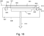
- a ceiling light apparatus includes a fixing bracket 601, a main housing 607 and a light source 609.
- the fixing bracket 601 is firstly fixed on a ceiling600.
- the fixing bracket 601 has a first end 602, a main part 603 and a second end 604.
- the main housing 607 includes a back cover 611.
- the back cover 611 has a first connector 605 and a second connector 606.
- the first end 602 is firstly attached to the first connector 605 and then the fist end 602 is rotated with respect to the first connector 605 to move the second end 604 to approach to the second connector 606 for elastically locking the second end 604 to the second connector 606.
- the light source 609 is enclosed by the main housing 607 for emitting a light 610 via a light opening 608 of the main housing 607.
- the second connector has an elastic unit connected to a button.
- Fig. 5 shows a fixing bracket 10 having a second end 12 to be fixed to a second connector.
- the second connector has a hook 40 fixed to an elastic unit like a spring.
- the hook 40 is further connected to a button 50. When users press the button, the second end 12 is released from the second connector.
- the elastic unit includes a spring with a hook for locking the second end of the fixing bracket, as shown in the example of Fig. 5 .
- a safety lock 613 is manually operated for disabling the button 614 to keep the second end 604 of the fixing bracket 601 held by the second connector 606.
- the button 614 is placed on lateral side of the main housing 607.
- the first end is a hook.
- the first connector is a shaft.
- Fig. 5 shows the first end 11 is a hook and the first connector 21 is a shaft.
- the hook is rotatable along the first connector 21.
- the hook is held by the shaft when the main housing is rotated with respect to the fixing bracket.
- the fixing bracket is an elongated bar, as shown in Fig. 18 .
- the main part has a wiring hole for an external wire to pass through.
- Fig. 16 shows a fixing bracket with a wiring hole 8824 in its main part 8821.
- Fig. 16 also shows the first end 8822 and the second end 8823 as hooks.
- the back cover has a concave wiring container for storing the external wire.
- Fig. 14 shows a concave wiring container 8813.
- the concave wiring container 8813 is located below the wiring hole.
- the back cover has a bracket groove for storing the fixing bracket.
- the main housing has a bracket groove 8812 for storing the fixing bracket 882.
- the back cover has a first groove 8811 for storing the first end of the fixing bracket 882 and has a second groove 8845 for storing the second end 8823 of the fixing bracket 882.
- the light source is disposed at an inner wall of the main housing for emitting the light to a light guide to change the light leaving via the light opening.
- Fig. 2 shows an example with a light guide 206 for directing light of the light source 201 to a light opening.
- a decoration ring 30 is detachably attached to a lateral wall of the main housing.
- the decoration ring 30 is replaceable. When different decoration rings are attached to the main housing, the light source is adjusted for emitting lights with different parameters.
- a lateral side of the main housing emits a second light.
- the light source has multiple types of LED modules.
- a manual switch is operated for adjusting a color temperature of the light.
- the manual switch 651 is placed on the fixing bracket 652.
- a driver stops electricity when the second end leaves the second connector.
- a switch is triggered to stop electricity to flow into the ceiling light apparatus.
- the fixing bracket routes an external power source via the first end and the second end to the first connector and the second connector.
- a driver box 655 is attached to the fixing bracket 652.
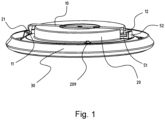
- Fig. 1 shows a ceiling light apparatus embodiment.
- the ceiling light apparatus has a fixing bracket 10.
- the fixing bracket 10 has a first end 11 and a second end 12 as hooks.
- a button 52 is operable for releasing the second end 12 from the second connector 51 to detach the main housing 20 from the fixing bracket 10.
- the first end 11 is connected to the first connector 21.
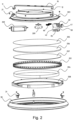
- Fig. 2 shows an exploded view of the example in Fig. 1 .
- the main housing has a back cover 203.
- a driver 202 for converting an external power to a driving current to the light source 201.
- the second connector 40 has a button 50 and an elastic unit 60.
- the button 50 may be pressed to release a hook from the second end 12.
- the manual switch 209 is used for adjusting a color temperature.
- the manual switch 209 is connected to the driver 202 for the driver 202 to adjust currents supplied to different types of LED modules to mix a desired color temperature.
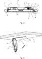
- Fig. 3 shows a cross-sectional view of the example in Fig. 2 .
- Fig. 5, Fig. 6 and Fig. 7 show steps on locking the second end of the fixing bracket to the second connector of the main housing.
- Fig. 8 shows fixing arm 23 being disposed on a lateral side of a main housing 20 to install a decoration ring 30.
- the bottom part 301 of the decoration ring adjusts light output effect.
- Fig. 9 shows another view for integrating the fixing bracket 10, the main housing 20 and the decoration ring.
- Fig. 10 shows a zoom-up view on how the fixing arm 23 to be fixed to the elastic clip 31.
- a tilt guiding surface 311 There is a block 233 disposed at an end 232 of the fixing arm 23.
- a stop block 233 at another end 231 of the fixing arm 23 to prevent releasing of the elastic clip 31.
- the fixing arm 23 has a fixing surface for contacting and holding the elastic clip 31.
- Fig. 11 shows another view of the example in Fig. 10 .
- Fig. 12 shows another view of the example in Fig. 10 and Fig. 11 .
- Fig. 13 shows a fixing bracket 882 to be installed to a main housing 881.
- the main part 8821 is stored in the groove 8812.
- Fig. 14 shows a cross-sectional view of the example in Fig. 13 .
- Fig. 15 shows a second connector that has a passing hole 8845 below the container groove 8812.
- a sliding frame 8842 attached to a main housing 8841.
- a hook 8843 to be attached to the second end of a fixing bracket using an elastic unit 8844 like a spring.
- Fig. 16 shows a fixing bracket
- Fig. 17 shows a shaft 883 with a support plate 8831 and a support tube 8832 for the first end of the fixing bracket to rotate with respect to the shaft 883.
Landscapes
- Engineering & Computer Science (AREA)
- General Engineering & Computer Science (AREA)
- Non-Portable Lighting Devices Or Systems Thereof (AREA)
- Arrangement Of Elements, Cooling, Sealing, Or The Like Of Lighting Devices (AREA)
Description
- The present invention is related to a lighting apparatus according to the preamble of claim 1.
- The time when the darkness is being lighten up by the light, human have noticed the need of lighting up this planet. Light has become one of the necessities we live with through the day and the night. During the darkness after sunset, there is no natural light, and human have been finding ways to light up the darkness with artificial light. From a torch, candles to the light we have nowadays, the use of light have been changed through decades and the development of lighting continues on.
- Early human found the control of fire which is a turning point of the human history. Fire provides light to bright up the darkness that have allowed human activities to continue into the darker and colder hour of the hour after sunset. Fire gives human beings the first form of light and heat to cook food, make tools, have heat to live through cold winter and lighting to see in the dark.
- Lighting is now not to be limited just for providing the light we need, but it is also for setting up the mood and atmosphere being created for an area. Proper lighting for an area needs a good combination of daylight conditions and artificial lights. There are many ways to improve lighting in a better cost and energy saving. LED lighting, a solid-state lamp that uses light-emitting diodes as the source of light, is a solution when it comes to energy-efficient lighting. LED lighting provides lower cost, energy saving and longer life span.
- The major use of the light emitting diodes is for illumination. The light emitting diodes is recently used in light bulb, light strip or light tube for a longer lifetime and a lower energy consumption of the light. The light emitting diodes shows a new type of illumination which brings more convenience to our lives. Nowadays, light emitting diode light may be often seen in the market with various forms and affordable prices.
- After the invention of LEDs, the neon indicator and incandescent lamps are gradually replaced. However, the cost of initial commercial LEDs was extremely high, making them rare to be applied for practical use. Also, LEDs only illuminated red light at early stage. The brightness of the light only could be used as indicator for it was too dark to illuminate an area. Unlike modern LEDs which are bound in transparent plastic cases, LEDs in early stage were packed in metal cases.
- In 1878, Thomas Edison tried to make a usable light bulb after experimenting different materials. In November 1879, Edison filed a patent for an electric lamp with a carbon filament and keep testing to find the perfect filament for his light bulb. The highest melting point of any chemical element, tungsten, was known by Edison to be an excellent material for light bulb filaments, but the machinery needed to produce super-fine tungsten wire was not available in the late 19th century. Tungsten is still the primary material used in incandescent bulb filaments today.
- Early candles were made in China in about 200 BC from whale fat and rice paper wick. They were made from other materials through time, like tallow, spermaceti, colza oil and beeswax until the discovery of paraffin wax which made production of candles cheap and affordable to everyone. Wick was also improved over time that made from paper, cotton, hemp and flax with different times and ways of burning. Although not a major light source now, candles are still here as decorative items and a light source in emergency situations. They are used for celebrations such as birthdays, religious rituals, for making atmosphere and as a decor.
- Illumination has been improved throughout the times. Even now, the lighting device we used today are still being improved. From the illumination of the sun to the time when human can control fire for providing illumination which changed human history, we have been improving the lighting source for a better efficiency and sense. From the invention of candle, gas lamp, electric carbon arc lamp, kerosene lamp, light bulb, fluorescent lamp to LED lamp, the improvement of illumination shows the necessity of light in human lives.
- There are various types of lighting apparatuses. When cost and light efficiency of LED have shown great effect compared with traditional lighting devices, people look for even better light output. It is important to recognize factors that can bring more satisfaction and light quality and flexibility.
- Ceiling light device are widely used. It is usually difficult to install a ceiling light device, particularly in a bath room.
-
EP 3 511 607 A1 discloses a ceiling lamp structure, comprising a lamp top tray and a lamp body disposed on the lamp top tray. -
EP 2 495 492 A1 discloses an illumination device including a light source part having a flat light emitting panel and a detachment part detachably attached to the light source part. -
KR 101 852 712 B1 -
US 2019/064429 A1 discloses a lighting arrangement including a light panel, a bracket, first and second retaining members and first and second connecting members. - It is beneficial and important to design a ceiling light that is easily to be installed to a ceiling.
- Object of the present invention is preferably to provide a ceiling light apparatus that can be easily installed.
- The above object is achieved by a ceiling light apparatus according to claim 1. Preferred embodiments are subject of the dependent claims.
- The ceiling light apparatus includes a fixing bracket, a main housing and a light source.
- The fixing bracket is firstly fixed on a ceiling.
- The fixing bracket has a first end, a main part and a second end.
- The main housing includes a back cover.
- The back cover has a first connector and a second connector.
- When the main housing is to be attached to the fixing bracket, the first end is firstly attached to the first connector and then the fist end is rotated with respect to the first connector to move the second end to approach to the second connector for elastically locking the second end to the second connector.
- The light source is enclosed by the main housing for emitting a light via a light opening of the main housing.
- The second connector has an elastic unit connected to a button.
- When the button is pressed, the second end of the fixing bracket is released from the second connector.
- The elastic unit includes a spring with a hook for locking the second end of the fixing bracket.
- In some embodiments, a safety lock is manually operated for disabling the button to keep the second end of the fixing bracket held by the second connector.
- In some embodiments, the button is placed on lateral side of the main housing.
- The first end is a hook, the first connector is a shaft.
- The hook is held by the shaft when the main housing is rotated with respect to the fixing bracket.
- In some embodiments, the fixing bracket is an elongated bar.
- In some embodiments, the main part has a wiring hole for an external wire to pass through.
- In some embodiments, the back cover has a concave wiring container for storing the external wire.
- The concave wiring container is located below the wiring hole.
- In some embodiments, the back cover has a bracket groove for storing the fixing bracket.
- In some embodiments, the back cover has a first groove for storing the first end of the fixing bracket and has a second groove for storing the second end of the fixing bracket.
- In some embodiments, the light source is disposed at an inner wall of the main housing for emitting the light to a light guide to change the light leaving via the light opening.
- In some embodiments, a decoration ring is detachably attached to a lateral wall of the main housing.
- In some embodiments, the decoration ring is replaceable. When different decoration rings are attached to the main housing, the light source is adjusted for emitting lights with different parameters.
- In some embodiments, a lateral side of the main housing emits a second light.
- In some embodiments, the light source has multiple types of LED modules.
- A manual switch is operated for adjusting a color temperature of the light.
- In some embodiments, the manual switch is placed on the fixing bracket.
- In some embodiments, a driver stops electricity when the second end leaves the second connector.
- In some embodiments, the fixing bracket routes an external power source via the first end and the second end to the first connector and the second connector.
- In some embodiments, a driver box is attached to the fixing bracket.
-
-
Fig. 1 illustrates a ceiling light apparatus embodiment. -
Fig. 2 illustrates an exploded view of the embodiment inFig. 1 . -
Fig. 3 illustrates a cross-sectional view of the example inFig. 1 . -
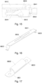
Fig. 4 illustrates an installation step in an example. -
Fig. 5 illustrates a first status when installing the ceiling light apparatus. -
Fig. 6 illustrates a second status when installing the ceiling light apparatus. -
Fig. 7 illustrates a third status when installing the ceiling light apparatus. -
Fig. 8 illustrates a decoration ring to be attached to the main housing. -
Fig. 9 illustrates the decoration ring attached to the main housing. -
Fig. 10 illustrates a zoom-up view of the connection of the decoration ring. -
Fig. 11 illustrates another view of the example inFig. 10 . -
Fig. 12 illustrates a cross-sectional view of the example inFig. 11 . -
Fig. 13 illustrates a back cover of the main housing. -
Fig. 14 illustrates a cross-sectional view of the ceiling light apparatus. -
Fig. 15 illustrates a second connector example. -
Fig. 16 illustrates a fixing bracket example. -
Fig. 17 illustrates a rotation shaft example. -
Fig. 18 illustrates another embodiment of a ceiling light apparatus. -
Fig. 19 shows an example of a fixing bracket. - In
Fig. 18 , a ceiling light apparatus includes a fixingbracket 601, amain housing 607 and alight source 609. - The fixing
bracket 601 is firstly fixed on a ceiling600. - The fixing
bracket 601 has afirst end 602, amain part 603 and asecond end 604. - The
main housing 607 includes aback cover 611. - The
back cover 611 has afirst connector 605 and asecond connector 606. - When the
main housing 607 is to be attached to the fixingbracket 601, the first end 602is firstly attached to thefirst connector 605 and then thefist end 602 is rotated with respect to thefirst connector 605 to move thesecond end 604 to approach to thesecond connector 606 for elastically locking thesecond end 604 to thesecond connector 606. - The
light source 609 is enclosed by themain housing 607 for emitting a light 610 via alight opening 608 of themain housing 607. - The second connector has an elastic unit connected to a button. For example,
Fig. 5 shows a fixingbracket 10 having asecond end 12 to be fixed to a second connector. The second connector has ahook 40 fixed to an elastic unit like a spring. Thehook 40 is further connected to abutton 50. When users press the button, thesecond end 12 is released from the second connector. - When the button is pressed, the second end of the fixing bracket is released from the second connector.
- The elastic unit includes a spring with a hook for locking the second end of the fixing bracket, as shown in the example of
Fig. 5 . - In
Fig. 18 , asafety lock 613 is manually operated for disabling thebutton 614 to keep thesecond end 604 of the fixingbracket 601 held by thesecond connector 606. - In some embodiments, the
button 614 is placed on lateral side of themain housing 607. - The first end is a hook.
- The first connector is a shaft.
- For example,
Fig. 5 shows thefirst end 11 is a hook and thefirst connector 21 is a shaft. The hook is rotatable along thefirst connector 21. - The hook is held by the shaft when the main housing is rotated with respect to the fixing bracket.
- In some embodiments, the fixing bracket is an elongated bar, as shown in
Fig. 18 . - In some embodiments, the main part has a wiring hole for an external wire to pass through. For example,
Fig. 16 shows a fixing bracket with awiring hole 8824 in itsmain part 8821.Fig. 16 also shows thefirst end 8822 and thesecond end 8823 as hooks. - In some embodiments, the back cover has a concave wiring container for storing the external wire. For example,
Fig. 14 shows aconcave wiring container 8813. - The
concave wiring container 8813 is located below the wiring hole. - In some embodiments, the back cover has a bracket groove for storing the fixing bracket. For example, in
Fig. 13 , the main housing has abracket groove 8812 for storing the fixingbracket 882. - In
Fig. 13 , the back cover has afirst groove 8811 for storing the first end of the fixingbracket 882 and has asecond groove 8845 for storing thesecond end 8823 of the fixingbracket 882. - In some embodiments, the light source is disposed at an inner wall of the main housing for emitting the light to a light guide to change the light leaving via the light opening.
- For example,
Fig. 2 shows an example with alight guide 206 for directing light of thelight source 201 to a light opening. - In
Fig. 2 , adecoration ring 30 is detachably attached to a lateral wall of the main housing. - In some embodiments, the
decoration ring 30 is replaceable. When different decoration rings are attached to the main housing, the light source is adjusted for emitting lights with different parameters. - In some embodiments, a lateral side of the main housing emits a second light.
- In some embodiments, the light source has multiple types of LED modules.
- A manual switch is operated for adjusting a color temperature of the light.
- In some embodiments, the
manual switch 651 is placed on the fixingbracket 652. - In some embodiments, a driver stops electricity when the second end leaves the second connector. For example, a switch is triggered to stop electricity to flow into the ceiling light apparatus.
- In some embodiments, the fixing bracket routes an external power source via the first end and the second end to the first connector and the second connector.
- In some embodiments, a
driver box 655 is attached to the fixingbracket 652. -
Fig. 1 shows a ceiling light apparatus embodiment. - In
Fig. 1 , the ceiling light apparatus has a fixingbracket 10. The fixingbracket 10 has afirst end 11 and asecond end 12 as hooks. Abutton 52 is operable for releasing thesecond end 12 from thesecond connector 51 to detach themain housing 20 from the fixingbracket 10. Thefirst end 11 is connected to thefirst connector 21. -
Fig. 2 shows an exploded view of the example inFig. 1 . - In addition to the components mentioned above, the main housing has a
back cover 203. There is adriver 202 for converting an external power to a driving current to thelight source 201. - The
second connector 40 has abutton 50 and anelastic unit 60. Thebutton 50 may be pressed to release a hook from thesecond end 12. There is a support base for holding thesecond connector 40. Themanual switch 209 is used for adjusting a color temperature. Themanual switch 209 is connected to thedriver 202 for thedriver 202 to adjust currents supplied to different types of LED modules to mix a desired color temperature. There is a reflector layer, alight guide 206 and a diffusion layer for changing light paths. - There is a
lateral ring 208 withelastic clips 31 for mounting adecoration ring 30. -
Fig. 3 shows a cross-sectional view of the example inFig. 2 . - In addition to the components mentioned above, there is a
container space 22 for storing the second end. - There is a
manual switch 209 for adjusting a color temperature of a light source stored in themain housing 20. - There is a
decoration ring 30 detachable attached to the main housing. - In
Fig. 4 , themain housing 20 is rotated with respect to the fixingbracket 10. Other components with the same reference numerals refer to the same components and are not repeated again in following disclosure. -
Fig. 5, Fig. 6 and Fig. 7 show steps on locking the second end of the fixing bracket to the second connector of the main housing. -
Fig. 8 shows fixing arm 23 being disposed on a lateral side of amain housing 20 to install adecoration ring 30. Thebottom part 301 of the decoration ring adjusts light output effect. - There is an
elastic clip 31 corresponding to the fixingarm 23 to fix thedecoration ring 30 to themain housing 20 by rotation. -
Fig. 9 shows another view for integrating the fixingbracket 10, themain housing 20 and the decoration ring. -
Fig. 10 shows a zoom-up view on how the fixingarm 23 to be fixed to theelastic clip 31. There is atilt guiding surface 311, ablock 233 disposed at anend 232 of the fixingarm 23. There is astop block 233 at anotherend 231 of the fixingarm 23 to prevent releasing of theelastic clip 31. - The fixing
arm 23 has a fixing surface for contacting and holding theelastic clip 31. -
Fig. 11 shows another view of the example inFig. 10 . -
Fig. 12 shows another view of the example inFig. 10 and Fig. 11 . -
Fig. 13 shows a fixingbracket 882 to be installed to amain housing 881. - There is a
second connector 884 with a passinghole 8845 for inserting thesecond end 8823 of the fixingbracket 882. Themain part 8821 is stored in thegroove 8812. There is adeeper groove 8811 with ashaft 883 as the first connector. Thedeeper groove 8811 is used for storing the first end of the fixingbracket 882. -
Fig. 14 shows a cross-sectional view of the example inFig. 13 . There is aconcave wiring groove 8813 for storing wire parts of an external wire. -
Fig. 15 shows a second connector that has a passinghole 8845 below thecontainer groove 8812. There is a slidingframe 8842 attached to amain housing 8841. There is ahook 8843 to be attached to the second end of a fixing bracket using anelastic unit 8844 like a spring. -
Fig. 16 shows a fixing bracket. -
Fig. 17 shows ashaft 883 with asupport plate 8831 and asupport tube 8832 for the first end of the fixing bracket to rotate with respect to theshaft 883. - The foregoing description, for purpose of explanation, has been described with reference to specific embodiments. However, the illustrative discussions above are not intended to be exhaustive or to limit the invention to the precise forms disclosed. Many modifications and variations are possible in view of the above teachings.
- The embodiments were chosen and described in order to best explain the principles of the techniques and their practical applications. Others skilled in the art are thereby enabled to best utilize the techniques and various embodiments with various modifications as are suited to the particular use contemplated.
- Although the disclosure and examples have been fully described with reference to the accompanying drawings, it is to be noted that various changes and modifications will become apparent to those skilled in the art.
Claims (13)
- A ceiling light apparatus, comprising:a fixing bracket (10, 601, 652, 882) to be fixed on a ceiling (600), wherein the fixing bracket (10, 601, 652, 882) has a first end (11, 602, 8822), a main part (603, 8821) and a second end (12, 604, 8823);a main housing (20, 607, 881, 8841) comprising a back cover (203, 611), wherein the back cover (203, 611) has a first connector (21, 605) and a second connector (40, 606, 884), when the main housing (20, 607, 881, 8841) is to be attached to the fixing bracket (10, 601, 652, 882), the first end (11, 602, 8822) is firstly attached to the first connector (21, 605) and then the first end is rotated with respect to the first connector (21, 605) to move the second end (12, 604, 8823) to approach to the second connector (40, 606, 884) for elastically locking the second end (12, 604, 8823) to the second connector (40, 606, 884); anda light source (201, 609) enclosed by the main housing (20, 607, 881, 8841) for emitting a light (610) via a light opening (608) of the main housing (20, 607, 881, 8841),wherein the first end (11, 602, 8822) is a hook (40, 8843), the first connector (21, 605) is a shaft (883), the hook (40, 8843) is held by the shaft (883) when the main housing (20, 607, 881, 8841) is rotated with respect to the fixing bracket (10, 601, 652, 882),characterized inthat the second connector (40, 606, 884) has an elastic unit (60, 8844) connected to a button (50, 52, 614) and comprising a spring with a hook (40, 8843) for locking the second end (12, 604, 8823) of the fixing bracket (10, 601, 652, 882), when the button (50, 52, 614) is pressed, the second end (12, 604, 8823) of the fixing bracket (10, 601, 652, 882) is released from the second connector (40, 606, 884).
- The ceiling light apparatus of claim 1, wherein a safety lock (613) is manually operated for disabling the button (50, 52, 614) to keep the second end (12, 604, 8823) of the fixing bracket (10, 601, 652, 882) held by the second connector (40, 606, 884).
- The ceiling light apparatus of claim 1 or 2, wherein the button (50, 52, 614) is placed on lateral side of the main housing (20, 607, 881, 8841).
- The ceiling light apparatus of any one of the preceding claims, wherein the fixing bracket (10, 601, 652, 882) is an elongated bar.
- The ceiling light apparatus of any one of the preceding claims, wherein the main part (603, 8821) has a wiring hole (8824) for an external wire to pass through, preferably, the back cover (203, 611) has a concave wiring container (8813) for storing the external wire, the concave wiring container (8813) is located below the wiring hole (8824).
- The ceiling light apparatus of any one of the preceding claims, wherein the back cover (203, 611) has a bracket groove (8812) for storing the fixing bracket (10, 601, 652, 882), preferably, the back cover (203, 611) has a first groove (8811) for storing the first end (11, 602, 8822) of the fixing bracket (10, 601, 652, 882) and has a second groove (8845) for storing the second end (12, 604, 8823) of the fixing bracket (10, 601, 652, 882).
- The ceiling light apparatus of any one of the preceding claims, wherein the light source (201, 609) is disposed at an inner wall of the main housing (20, 607, 881, 8841) for emitting the light (610) to a light guide (206) to change the light leaving via the light opening (608).
- The ceiling light apparatus of any one of the preceding claims, wherein a decoration ring (30) is detachably attached to a lateral wall of the main housing (20, 607, 881, 8841), preferably, the decoration ring (30) is replaceable, when different decoration rings (30) are attached to the main housing (20, 607, 881, 8841), the light source (201, 609) is adjusted for emitting lights with different parameters.
- The ceiling light apparatus of any one of the preceding claims, wherein a lateral side of the main housing (20, 607, 881, 8841) emits a second light.
- The ceiling light apparatus of any one of the preceding claims, wherein the light source (201, 609) has multiple types of LED modules, a manual switch (209, 651) is operated for adjusting a color temperature of the light, preferably, the manual switch (209, 651) is placed on the fixing bracket (10, 601, 652, 882).
- The ceiling light apparatus of any one of the preceding claims, wherein a driver stops electricity when the second end (12, 604, 8823) leaves the second connector (40, 606, 884).
- The ceiling light apparatus of any one of the preceding claims, wherein the fixing bracket (10, 601, 652, 882) routes an external power source via the first end (11, 602, 8822) and the second end (12, 604, 8823) to the first connector (21, 605) and the second connector (40, 606, 884).
- The ceiling light apparatus of any one of the preceding claims, wherein a driver box (655) is attached to the fixing bracket (10, 601, 652, 882).
Applications Claiming Priority (2)
| Application Number | Priority Date | Filing Date | Title |
|---|---|---|---|
| CN202020191741.3U CN211780588U (en) | 2020-02-20 | 2020-02-20 | A self-locking installation ceiling lamp |
| CN202021204278.8U CN212361763U (en) | 2020-06-24 | 2020-06-24 | Surface mounted lamp |
Publications (2)
| Publication Number | Publication Date |
|---|---|
| EP3869094A1 EP3869094A1 (en) | 2021-08-25 |
| EP3869094B1 true EP3869094B1 (en) | 2023-07-12 |
Family
ID=74672144
Family Applications (1)
| Application Number | Title | Priority Date | Filing Date |
|---|---|---|---|
| EP21158124.4A Active EP3869094B1 (en) | 2020-02-20 | 2021-02-19 | Ceiling light apparatus |
Country Status (2)
| Country | Link |
|---|---|
| US (1) | US20210262625A1 (en) |
| EP (1) | EP3869094B1 (en) |
Cited By (1)
| Publication number | Priority date | Publication date | Assignee | Title |
|---|---|---|---|---|
| TWI841505B (en) * | 2023-11-03 | 2024-05-01 | 展晟照明股份有限公司 | The fixed installation of lighting fixtures and their applications |
Families Citing this family (6)
| Publication number | Priority date | Publication date | Assignee | Title |
|---|---|---|---|---|
| USD953598S1 (en) * | 2021-05-19 | 2022-05-31 | Shenzhen Ouchang Technology Co., Ltd. | LED ceiling light |
| US11359780B1 (en) * | 2021-08-05 | 2022-06-14 | Dong Guan Jia Sheng Lighting Technology Co., Ltd. China | Ceiling lamp bracket assembly without using screws |
| US20230040979A1 (en) * | 2021-08-05 | 2023-02-09 | Dong Guan Jia Sheng Lighting Technology Co., Ltd. China | Ceiling Lamp Bracket Assembly Without Free Screws |
| USD1044095S1 (en) * | 2022-02-17 | 2024-09-24 | Thorn Lighting Limited | Ceiling light |
| CN219713225U (en) * | 2023-01-03 | 2023-09-19 | 漳州立达信光电子科技有限公司 | Panel light |
| CN221258688U (en) * | 2023-11-20 | 2024-07-02 | 深圳市联域光电股份有限公司 | LED lamp |
Family Cites Families (9)
| Publication number | Priority date | Publication date | Assignee | Title |
|---|---|---|---|---|
| US2477131A (en) * | 1945-12-22 | 1949-07-26 | Gen Electric | Junction box |
| JPS57127406U (en) * | 1981-02-02 | 1982-08-09 | ||
| JP5834219B2 (en) * | 2011-03-04 | 2015-12-16 | パナソニックIpマネジメント株式会社 | Lighting device |
| CN106151992A (en) * | 2016-09-06 | 2016-11-23 | 北京小米移动软件有限公司 | Ceiling light structure |
| KR101852712B1 (en) * | 2017-01-18 | 2018-04-26 | 박용우 | Directly attached type light emitting diode flat panel luminaires |
| CN107289379B (en) * | 2017-06-08 | 2023-09-19 | 东莞莹辉灯饰有限公司 | Fast-assembling ceiling lamp convenient to wire |
| US10353141B2 (en) * | 2017-08-23 | 2019-07-16 | CP IP Holdings Limited | Lighting arrangement |
| CN109163264B (en) * | 2018-09-26 | 2024-03-29 | 深圳民爆光电股份有限公司 | LED lamp |
| US20200191344A1 (en) * | 2018-12-12 | 2020-06-18 | ETi Solid State Lighting Inc. | Led light fixture with nightlight |
-
2021
- 2021-02-18 US US17/179,371 patent/US20210262625A1/en not_active Abandoned
- 2021-02-19 EP EP21158124.4A patent/EP3869094B1/en active Active
Cited By (1)
| Publication number | Priority date | Publication date | Assignee | Title |
|---|---|---|---|---|
| TWI841505B (en) * | 2023-11-03 | 2024-05-01 | 展晟照明股份有限公司 | The fixed installation of lighting fixtures and their applications |
Also Published As
| Publication number | Publication date |
|---|---|
| EP3869094A1 (en) | 2021-08-25 |
| US20210262625A1 (en) | 2021-08-26 |
Similar Documents
| Publication | Publication Date | Title |
|---|---|---|
| EP3869094A1 (en) | Ceiling light apparatus | |
| US11674670B2 (en) | Downlight apparatus | |
| US11953178B2 (en) | Downlight apparatus | |
| US20220074557A1 (en) | Downlight apparatus | |
| US20210337640A1 (en) | Lighting apparatus | |
| US11598511B2 (en) | Lighting apparatus | |
| US11598514B2 (en) | Downlight apparatus | |
| US11105496B1 (en) | Downlight apparatus having a rotation unit and shifting unit for moving and rotating light module with respect to a host housing | |
| US11598501B2 (en) | Downlight apparatus | |
| US11566779B2 (en) | Lighting apparatus | |
| US11852310B2 (en) | Lighting apparatus | |
| US20210116087A1 (en) | Lighting apparatus | |
| US11598489B2 (en) | Light bulb apparatus | |
| US11946614B2 (en) | Downlight apparatus with angularly adjustable light source and support | |
| US11168870B2 (en) | Lighting apparatus | |
| US11085622B1 (en) | Lighting apparatus | |
| US11193667B2 (en) | Lighting apparatus | |
| US11512845B2 (en) | Lighting apparatus with heat dissipation unit | |
| US12031705B2 (en) | Lighting apparatus | |
| US11543089B2 (en) | Lighting apparatus | |
| US20210116086A1 (en) | Lighting apparatus | |
| US11415306B2 (en) | Panel light apparatus |
Legal Events
| Date | Code | Title | Description |
|---|---|---|---|
| PUAI | Public reference made under article 153(3) epc to a published international application that has entered the european phase |
Free format text: ORIGINAL CODE: 0009012 |
|
| STAA | Information on the status of an ep patent application or granted ep patent |
Free format text: STATUS: EXAMINATION IS IN PROGRESS |
|
| 17P | Request for examination filed |
Effective date: 20210219 |
|
| AK | Designated contracting states |
Kind code of ref document: A1 Designated state(s): AL AT BE BG CH CY CZ DE DK EE ES FI FR GB GR HR HU IE IS IT LI LT LU LV MC MK MT NL NO PL PT RO RS SE SI SK SM TR |
|
| RIC1 | Information provided on ipc code assigned before grant |
Ipc: F21V 8/00 20060101ALN20230120BHEP Ipc: F21Y 113/10 20160101ALN20230120BHEP Ipc: F21Y 103/33 20160101ALN20230120BHEP Ipc: F21Y 115/10 20160101ALN20230120BHEP Ipc: F21V 17/14 20060101ALN20230120BHEP Ipc: F21S 8/04 20060101ALI20230120BHEP Ipc: F21V 17/16 20060101ALI20230120BHEP Ipc: F21V 21/03 20060101AFI20230120BHEP |
|
| GRAP | Despatch of communication of intention to grant a patent |
Free format text: ORIGINAL CODE: EPIDOSNIGR1 |
|
| STAA | Information on the status of an ep patent application or granted ep patent |
Free format text: STATUS: GRANT OF PATENT IS INTENDED |
|
| INTG | Intention to grant announced |
Effective date: 20230306 |
|
| GRAS | Grant fee paid |
Free format text: ORIGINAL CODE: EPIDOSNIGR3 |
|
| GRAA | (expected) grant |
Free format text: ORIGINAL CODE: 0009210 |
|
| STAA | Information on the status of an ep patent application or granted ep patent |
Free format text: STATUS: THE PATENT HAS BEEN GRANTED |
|
| AK | Designated contracting states |
Kind code of ref document: B1 Designated state(s): AL AT BE BG CH CY CZ DE DK EE ES FI FR GB GR HR HU IE IS IT LI LT LU LV MC MK MT NL NO PL PT RO RS SE SI SK SM TR |
|
| REG | Reference to a national code |
Ref country code: CH Ref legal event code: EP |
|
| REG | Reference to a national code |
Ref country code: IE Ref legal event code: FG4D |
|
| REG | Reference to a national code |
Ref country code: DE Ref legal event code: R096 Ref document number: 602021003340 Country of ref document: DE |
|
| REG | Reference to a national code |
Ref country code: LT Ref legal event code: MG9D |
|
| REG | Reference to a national code |
Ref country code: NL Ref legal event code: MP Effective date: 20230712 |
|
| REG | Reference to a national code |
Ref country code: AT Ref legal event code: MK05 Ref document number: 1587541 Country of ref document: AT Kind code of ref document: T Effective date: 20230712 |
|
| PG25 | Lapsed in a contracting state [announced via postgrant information from national office to epo] |
Ref country code: NL Free format text: LAPSE BECAUSE OF FAILURE TO SUBMIT A TRANSLATION OF THE DESCRIPTION OR TO PAY THE FEE WITHIN THE PRESCRIBED TIME-LIMIT Effective date: 20230712 |
|
| PG25 | Lapsed in a contracting state [announced via postgrant information from national office to epo] |
Ref country code: GR Free format text: LAPSE BECAUSE OF FAILURE TO SUBMIT A TRANSLATION OF THE DESCRIPTION OR TO PAY THE FEE WITHIN THE PRESCRIBED TIME-LIMIT Effective date: 20231013 |
|
| PG25 | Lapsed in a contracting state [announced via postgrant information from national office to epo] |
Ref country code: ES Free format text: LAPSE BECAUSE OF FAILURE TO SUBMIT A TRANSLATION OF THE DESCRIPTION OR TO PAY THE FEE WITHIN THE PRESCRIBED TIME-LIMIT Effective date: 20230712 |
|
| PG25 | Lapsed in a contracting state [announced via postgrant information from national office to epo] |
Ref country code: IS Free format text: LAPSE BECAUSE OF FAILURE TO SUBMIT A TRANSLATION OF THE DESCRIPTION OR TO PAY THE FEE WITHIN THE PRESCRIBED TIME-LIMIT Effective date: 20231112 |
|
| PG25 | Lapsed in a contracting state [announced via postgrant information from national office to epo] |
Ref country code: SE Free format text: LAPSE BECAUSE OF FAILURE TO SUBMIT A TRANSLATION OF THE DESCRIPTION OR TO PAY THE FEE WITHIN THE PRESCRIBED TIME-LIMIT Effective date: 20230712 Ref country code: RS Free format text: LAPSE BECAUSE OF FAILURE TO SUBMIT A TRANSLATION OF THE DESCRIPTION OR TO PAY THE FEE WITHIN THE PRESCRIBED TIME-LIMIT Effective date: 20230712 Ref country code: PT Free format text: LAPSE BECAUSE OF FAILURE TO SUBMIT A TRANSLATION OF THE DESCRIPTION OR TO PAY THE FEE WITHIN THE PRESCRIBED TIME-LIMIT Effective date: 20231113 Ref country code: NO Free format text: LAPSE BECAUSE OF FAILURE TO SUBMIT A TRANSLATION OF THE DESCRIPTION OR TO PAY THE FEE WITHIN THE PRESCRIBED TIME-LIMIT Effective date: 20231012 Ref country code: LV Free format text: LAPSE BECAUSE OF FAILURE TO SUBMIT A TRANSLATION OF THE DESCRIPTION OR TO PAY THE FEE WITHIN THE PRESCRIBED TIME-LIMIT Effective date: 20230712 Ref country code: LT Free format text: LAPSE BECAUSE OF FAILURE TO SUBMIT A TRANSLATION OF THE DESCRIPTION OR TO PAY THE FEE WITHIN THE PRESCRIBED TIME-LIMIT Effective date: 20230712 Ref country code: IS Free format text: LAPSE BECAUSE OF FAILURE TO SUBMIT A TRANSLATION OF THE DESCRIPTION OR TO PAY THE FEE WITHIN THE PRESCRIBED TIME-LIMIT Effective date: 20231112 Ref country code: HR Free format text: LAPSE BECAUSE OF FAILURE TO SUBMIT A TRANSLATION OF THE DESCRIPTION OR TO PAY THE FEE WITHIN THE PRESCRIBED TIME-LIMIT Effective date: 20230712 Ref country code: GR Free format text: LAPSE BECAUSE OF FAILURE TO SUBMIT A TRANSLATION OF THE DESCRIPTION OR TO PAY THE FEE WITHIN THE PRESCRIBED TIME-LIMIT Effective date: 20231013 Ref country code: FI Free format text: LAPSE BECAUSE OF FAILURE TO SUBMIT A TRANSLATION OF THE DESCRIPTION OR TO PAY THE FEE WITHIN THE PRESCRIBED TIME-LIMIT Effective date: 20230712 Ref country code: ES Free format text: LAPSE BECAUSE OF FAILURE TO SUBMIT A TRANSLATION OF THE DESCRIPTION OR TO PAY THE FEE WITHIN THE PRESCRIBED TIME-LIMIT Effective date: 20230712 Ref country code: AT Free format text: LAPSE BECAUSE OF FAILURE TO SUBMIT A TRANSLATION OF THE DESCRIPTION OR TO PAY THE FEE WITHIN THE PRESCRIBED TIME-LIMIT Effective date: 20230712 |
|
| PG25 | Lapsed in a contracting state [announced via postgrant information from national office to epo] |
Ref country code: PL Free format text: LAPSE BECAUSE OF FAILURE TO SUBMIT A TRANSLATION OF THE DESCRIPTION OR TO PAY THE FEE WITHIN THE PRESCRIBED TIME-LIMIT Effective date: 20230712 |
|
| REG | Reference to a national code |
Ref country code: DE Ref legal event code: R097 Ref document number: 602021003340 Country of ref document: DE |
|
| PG25 | Lapsed in a contracting state [announced via postgrant information from national office to epo] |
Ref country code: SM Free format text: LAPSE BECAUSE OF FAILURE TO SUBMIT A TRANSLATION OF THE DESCRIPTION OR TO PAY THE FEE WITHIN THE PRESCRIBED TIME-LIMIT Effective date: 20230712 Ref country code: RO Free format text: LAPSE BECAUSE OF FAILURE TO SUBMIT A TRANSLATION OF THE DESCRIPTION OR TO PAY THE FEE WITHIN THE PRESCRIBED TIME-LIMIT Effective date: 20230712 Ref country code: EE Free format text: LAPSE BECAUSE OF FAILURE TO SUBMIT A TRANSLATION OF THE DESCRIPTION OR TO PAY THE FEE WITHIN THE PRESCRIBED TIME-LIMIT Effective date: 20230712 Ref country code: DK Free format text: LAPSE BECAUSE OF FAILURE TO SUBMIT A TRANSLATION OF THE DESCRIPTION OR TO PAY THE FEE WITHIN THE PRESCRIBED TIME-LIMIT Effective date: 20230712 Ref country code: CZ Free format text: LAPSE BECAUSE OF FAILURE TO SUBMIT A TRANSLATION OF THE DESCRIPTION OR TO PAY THE FEE WITHIN THE PRESCRIBED TIME-LIMIT Effective date: 20230712 Ref country code: SK Free format text: LAPSE BECAUSE OF FAILURE TO SUBMIT A TRANSLATION OF THE DESCRIPTION OR TO PAY THE FEE WITHIN THE PRESCRIBED TIME-LIMIT Effective date: 20230712 |
|
| PLBE | No opposition filed within time limit |
Free format text: ORIGINAL CODE: 0009261 |
|
| STAA | Information on the status of an ep patent application or granted ep patent |
Free format text: STATUS: NO OPPOSITION FILED WITHIN TIME LIMIT |
|
| PG25 | Lapsed in a contracting state [announced via postgrant information from national office to epo] |
Ref country code: IT Free format text: LAPSE BECAUSE OF FAILURE TO SUBMIT A TRANSLATION OF THE DESCRIPTION OR TO PAY THE FEE WITHIN THE PRESCRIBED TIME-LIMIT Effective date: 20230712 |
|
| 26N | No opposition filed |
Effective date: 20240415 |
|
| PG25 | Lapsed in a contracting state [announced via postgrant information from national office to epo] |
Ref country code: SI Free format text: LAPSE BECAUSE OF FAILURE TO SUBMIT A TRANSLATION OF THE DESCRIPTION OR TO PAY THE FEE WITHIN THE PRESCRIBED TIME-LIMIT Effective date: 20230712 |
|
| PG25 | Lapsed in a contracting state [announced via postgrant information from national office to epo] |
Ref country code: MC Free format text: LAPSE BECAUSE OF FAILURE TO SUBMIT A TRANSLATION OF THE DESCRIPTION OR TO PAY THE FEE WITHIN THE PRESCRIBED TIME-LIMIT Effective date: 20230712 |
|
| REG | Reference to a national code |
Ref country code: CH Ref legal event code: PL |
|
| PG25 | Lapsed in a contracting state [announced via postgrant information from national office to epo] |
Ref country code: LU Free format text: LAPSE BECAUSE OF NON-PAYMENT OF DUE FEES Effective date: 20240219 |
|
| PG25 | Lapsed in a contracting state [announced via postgrant information from national office to epo] |
Ref country code: CH Free format text: LAPSE BECAUSE OF NON-PAYMENT OF DUE FEES Effective date: 20240229 |
|
| PG25 | Lapsed in a contracting state [announced via postgrant information from national office to epo] |
Ref country code: LU Free format text: LAPSE BECAUSE OF NON-PAYMENT OF DUE FEES Effective date: 20240219 Ref country code: CH Free format text: LAPSE BECAUSE OF NON-PAYMENT OF DUE FEES Effective date: 20240229 |
|
| PG25 | Lapsed in a contracting state [announced via postgrant information from national office to epo] |
Ref country code: BG Free format text: LAPSE BECAUSE OF FAILURE TO SUBMIT A TRANSLATION OF THE DESCRIPTION OR TO PAY THE FEE WITHIN THE PRESCRIBED TIME-LIMIT Effective date: 20230712 |
|
| PG25 | Lapsed in a contracting state [announced via postgrant information from national office to epo] |
Ref country code: BG Free format text: LAPSE BECAUSE OF FAILURE TO SUBMIT A TRANSLATION OF THE DESCRIPTION OR TO PAY THE FEE WITHIN THE PRESCRIBED TIME-LIMIT Effective date: 20230712 |
|
| REG | Reference to a national code |
Ref country code: BE Ref legal event code: MM Effective date: 20240229 |
|
| PG25 | Lapsed in a contracting state [announced via postgrant information from national office to epo] |
Ref country code: BE Free format text: LAPSE BECAUSE OF NON-PAYMENT OF DUE FEES Effective date: 20240229 |
|
| PG25 | Lapsed in a contracting state [announced via postgrant information from national office to epo] |
Ref country code: IE Free format text: LAPSE BECAUSE OF NON-PAYMENT OF DUE FEES Effective date: 20240219 |
|
| PG25 | Lapsed in a contracting state [announced via postgrant information from national office to epo] |
Ref country code: IE Free format text: LAPSE BECAUSE OF NON-PAYMENT OF DUE FEES Effective date: 20240219 Ref country code: BE Free format text: LAPSE BECAUSE OF NON-PAYMENT OF DUE FEES Effective date: 20240229 |
|
| PG25 | Lapsed in a contracting state [announced via postgrant information from national office to epo] |
Ref country code: CY Free format text: LAPSE BECAUSE OF FAILURE TO SUBMIT A TRANSLATION OF THE DESCRIPTION OR TO PAY THE FEE WITHIN THE PRESCRIBED TIME-LIMIT; INVALID AB INITIO Effective date: 20210219 |
|
| PG25 | Lapsed in a contracting state [announced via postgrant information from national office to epo] |
Ref country code: HU Free format text: LAPSE BECAUSE OF FAILURE TO SUBMIT A TRANSLATION OF THE DESCRIPTION OR TO PAY THE FEE WITHIN THE PRESCRIBED TIME-LIMIT; INVALID AB INITIO Effective date: 20210219 |
|
| PG25 | Lapsed in a contracting state [announced via postgrant information from national office to epo] |
Ref country code: TR Free format text: LAPSE BECAUSE OF FAILURE TO SUBMIT A TRANSLATION OF THE DESCRIPTION OR TO PAY THE FEE WITHIN THE PRESCRIBED TIME-LIMIT Effective date: 20230712 |
|
| PGFP | Annual fee paid to national office [announced via postgrant information from national office to epo] |
Ref country code: GB Payment date: 20251218 Year of fee payment: 6 |
|
| PGFP | Annual fee paid to national office [announced via postgrant information from national office to epo] |
Ref country code: FR Payment date: 20251218 Year of fee payment: 6 |
|
| PGFP | Annual fee paid to national office [announced via postgrant information from national office to epo] |
Ref country code: DE Payment date: 20251217 Year of fee payment: 6 |