EP3869009A1 - Damper for a turbine blade - Google Patents
Damper for a turbine blade Download PDFInfo
- Publication number
- EP3869009A1 EP3869009A1 EP20211380.9A EP20211380A EP3869009A1 EP 3869009 A1 EP3869009 A1 EP 3869009A1 EP 20211380 A EP20211380 A EP 20211380A EP 3869009 A1 EP3869009 A1 EP 3869009A1
- Authority
- EP
- European Patent Office
- Prior art keywords
- elongated body
- dampening
- turbine
- turbine blade
- masses
- Prior art date
- Legal status (The legal status is an assumption and is not a legal conclusion. Google has not performed a legal analysis and makes no representation as to the accuracy of the status listed.)
- Granted
Links
Images


Classifications
-
- F—MECHANICAL ENGINEERING; LIGHTING; HEATING; WEAPONS; BLASTING
- F01—MACHINES OR ENGINES IN GENERAL; ENGINE PLANTS IN GENERAL; STEAM ENGINES
- F01D—NON-POSITIVE DISPLACEMENT MACHINES OR ENGINES, e.g. STEAM TURBINES
- F01D5/00—Blades; Blade-carrying members; Heating, heat-insulating, cooling or antivibration means on the blades or the members
- F01D5/12—Blades
- F01D5/14—Form or construction
- F01D5/16—Form or construction for counteracting blade vibration
-
- F—MECHANICAL ENGINEERING; LIGHTING; HEATING; WEAPONS; BLASTING
- F01—MACHINES OR ENGINES IN GENERAL; ENGINE PLANTS IN GENERAL; STEAM ENGINES
- F01D—NON-POSITIVE DISPLACEMENT MACHINES OR ENGINES, e.g. STEAM TURBINES
- F01D5/00—Blades; Blade-carrying members; Heating, heat-insulating, cooling or antivibration means on the blades or the members
- F01D5/12—Blades
- F01D5/14—Form or construction
- F01D5/18—Hollow blades, i.e. blades with cooling or heating channels or cavities; Heating, heat-insulating or cooling means on blades
-
- F—MECHANICAL ENGINEERING; LIGHTING; HEATING; WEAPONS; BLASTING
- F05—INDEXING SCHEMES RELATING TO ENGINES OR PUMPS IN VARIOUS SUBCLASSES OF CLASSES F01-F04
- F05D—INDEXING SCHEME FOR ASPECTS RELATING TO NON-POSITIVE-DISPLACEMENT MACHINES OR ENGINES, GAS-TURBINES OR JET-PROPULSION PLANTS
- F05D2220/00—Application
- F05D2220/30—Application in turbines
-
- F—MECHANICAL ENGINEERING; LIGHTING; HEATING; WEAPONS; BLASTING
- F05—INDEXING SCHEMES RELATING TO ENGINES OR PUMPS IN VARIOUS SUBCLASSES OF CLASSES F01-F04
- F05D—INDEXING SCHEME FOR ASPECTS RELATING TO NON-POSITIVE-DISPLACEMENT MACHINES OR ENGINES, GAS-TURBINES OR JET-PROPULSION PLANTS
- F05D2260/00—Function
- F05D2260/96—Preventing, counteracting or reducing vibration or noise
Definitions
- Embodiments of the subject matter described herein relate to dampening elongated bodies that reduce or eliminate vibrations of blades in rotor assemblies.
- Rotor assemblies are used in various systems, such as gas turbine engines and turbochargers.
- pressurized air that is produced in a compression system is mixed with fuel in a combustor and ignited, generating hot combustion gases which flow through one or more turbine stages.
- the turbine stages extract energy from the hot combustion gases for generating engine thrust to propel a vehicle (e.g., a train, an aircraft, a marine vessel, etc.) or to power a load, such as an electrical generator.
- the gas turbine includes a rotor assembly having a plurality of blades extending radially outward from a rotor disk.
- Large industrial gas turbine (IGT) blades are exposed to unsteady aerodynamic loading, causing the blades to vibrate. If these vibrations are not adequately damped, they may cause high cycle fatigue and premature failure in the blades.
- the last-stage blade (LSB) is the tallest and therefore is the most vibrationally challenged component of the turbine.
- Vibration damping methods for turbine blades include platform dampers, damping wires, shrouds etc. However, each method includes drawbacks.
- platform dampers sit underneath the blade platform and are effective for medium and long shank blades which have motion at the blade platform.
- IGT aft-stage blades have short shanks to reduce the weight of the blade and in turn reduce the pull load on the rotor which renders platform dampers ineffective.
- tip shrouds and in particular part-span-shroud blades have a high contact load that may prevent the shroud contact surfaces from sliding and providing damping.
- a second part span shroud may be added, the second part span shroud adds weight and may reduce performance of the rotor assembly.
- a turbine damper may be provided that may include an elongated body sized to fit inside a turbine blade, the elongated body elongated along a radial direction of the turbine blade relative to a rotation axis of the turbine blade, and plural dampening masses coupled with the elongated body and disposed at different locations along the radial direction.
- the plural dampening masses may be one or more of sized to dampen different vibration modes of the turbine blade, or moveable relative to and along the elongated body in the radial direction.
- a turbine damper may be provided that may include an elongated body that may be sized to fit inside a turbine blade, the elongated body elongated along a radial direction of the turbine blade relative to a rotation axis of the turbine blade, and plural dampening masses may be coupled with the elongated body and disposed at different locations along the radial direction, wherein the dampening masses are sized to dampen different vibration modes of the turbine blade.
- a turbine damper may be provided that may include an elongated body that may be sized to fit inside a turbine blade, the elongated body elongated along a radial direction of the turbine blade relative to a rotation axis of the turbine blade, and plural dampening masses coupled with the elongated body and disposed at different locations along the radial direction, The dampening masses may be moveable relative to and along the elongated body in the radial direction.
- the turbine dampers may be located within each blade of a blade assembly for a turbine and comprise an elongated body and dampening masses spaced along the elongated body.
- the dampening masses may move in relation to the elongated body and move between mass stops also disposed within the blade.
- the mass stops may be secured to the elongated body or formed from a housing encasing the elongated body.
- the movable dampening masses function to provide friction dampening for the blade.
- the dampening masses may be fixed to the elongated body and not moveable along the elongated body. By being fixed to the elongated body, the dampening masses provide impact dampening within the blade.
- tip shrouds used for dampening may be eliminated.
- Figure 1 shows a schematic view of a gas turbine engine system 10 according to an embodiment which includes a compressor 15, a combustion system 25, and a turbine 40.
- the compressor and turbine may include rows of blades that are axially stacked in stages. Each stage includes a row of circumferentially spaced blades, which are fixed, and a row of rotor blades, which rotate about one or more central shafts.
- the compressor rotor blades rotate about the shaft and, acting in concert with the stator blades, compress a flow of air 20.
- the compression system delivers the compressed flow of air to a combustion system.
- the combustion system 25 mixes the compressed flow 20 of air with a pressurized flow of fuel 30 and ignites the mixture to provide a flow of combustion gases 35.
- the flow of combustion gases may be delivered to the turbine 40.
- the turbine rotor blades rotate about the shaft and, acting in concert with the stator blades, expand the combustion gases 35 through the turbine 40 so as to produce mechanical work.
- the mechanical work produced in the turbine 40 drives the compression system 15 via one or more shafts 45 and may drive an external load 50, such as an electrical generator or the like, via one or more shafts 46.
- the gas turbine engine system 10 may have different shaft, compressor, and turbine configurations and use other types of components in other embodiments. Other types of turbines may also be used.
- the embodiments of the rotor assembly described herein may be used in the gas turbine engine system 10, such as on the turbine 40 or the compressor 15.
- the embodiments of the rotor assembly described herein are not limited to use in the engine system 10 shown in Figure 1 , and may be used in other devices, such as turbochargers, HVAC systems, and the like.
- FIG 2 illustrates a portion of a rotor disk 133 and a pair of blades 124, 124A of a rotor assembly 122 of a turbine according to one embodiment.
- the turbine is the turbine illustrated in Figure 1 .
- Each blade 124, 124A includes portions of a turbine damper disposed therein as will be described in more detail in relation to Figures 4-6 .
- the rotor disk 133 has a curved outer periphery
- the rotor assembly 122 further includes additional blades 124 extending radially from the rotor disk 133 at spaced apart locations along the outer periphery of the rotor disk 133.
- the blades 124 have mounting segments 208 that mount to the rotor disk 133, airfoils 200 that extend from the rotor disk 133, and optionally also include platforms 206 disposed between the airfoil 200 and the mounting segment 208.
- the platforms 206 extend laterally outward from the corresponding blades 124 towards at least one neighboring (e.g., immediately adjacent) blade 124.
- the mounting segments 208 are received in corresponding support slots 210 of the rotor disk 133 to mount the blades 124.
- the mounting segments 208 may be referred to herein as dovetails 208 due to the shapes of the mounting segments 208.
- the support slots 210 have a complementary shape to the dovetails 208.
- the airfoils 200 extend from the platforms 206 to distal tips 204 of the airfoils 200.
- the airfoils 200 receive energy from the gas (e.g., air, exhaust, or the like) flowing through the rotor assembly 122.
- the blades 124 may have a pair of first and second shrouds 216, 218 that extend outward from the airfoil 200.
- the shrouds 216, 218 may be located at a common location along a length of the airfoil 200 between the platform 206 and the distal tip 204.
- the shrouds 216, 218 are mid-span shrouds that are located in a medial region 220 of the airfoil 200 that is spaced apart from the distal tip 204 and the platform 206.
- the shrouds 216, 218 may be tip shrouds that are located at the distal tips 204 of the airfoils 200.
- the blades 124 may include both mid-span shrouds and tip shrouds ( Figure 3 ). The first and second shrouds 216, 218 in each pair extend in generally opposite directions from the respective airfoil 200.
- the first shroud 216 may extend from a first side (e.g., a pressure side) of the airfoil 200, and the second shroud 218 extends from an opposite second side (e.g., a suction side) of the airfoil 200.
- first side e.g., a pressure side
- second side e.g., a suction side
- the shrouds 216, 218 of the blades 124 extend circumferentially and define a shroud ring that is concentric with the rotor disc 133.
- the shrouds 216, 218 are cantilevered, extending from attachment ends 222 connected to the airfoil 200 to distal ends 224 that are remote from the airfoil 200.
- the distal end 224 of the first shroud 216 of a first blade 124A is disposed at least proximate to the distal end 224 of the second shroud 218 of a neighboring, second blade 124B.
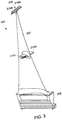
- FIG 3 is a perspective view of a blade of the rotor assembly (shown in Figure 2 ) according to an alternative embodiment.
- the airfoil of the blade extends from the platform to the distal tip.
- the airfoil includes a first set 302 of mid-span shrouds and a second set 304 of tip shrouds.
- the first set of mid-span shrouds include mid-span shrouds 216A, 218A.
- the tip shrouds include a carrier shroud 216B and a lid shroud 218B, which are located at the distal tip 204. Therefore, in some example embodiments, the blade may include multiple sets of shrouds.
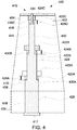
- FIG 4 illustrates a blade assembly 400 that includes an airfoil 402 that represents a blade.
- the blade assembly 400 may include the blade of Figures 2-3 .
- the airfoil 402 extends from a distal tip 404 to a platform 406.
- the airfoil 402 may be comprised of a housing 408 that includes a hollow interior 410 that extends from the distil tip 404 to the platform 406.
- the housing 408 may refer to both the wall of the air foil itself, or to a separate structure that is within the airfoil and contains a turbine damper 412.
- the housing 408 is the airfoil or blade interior 410.
- disposed within the hollow interior of the housing 408 may be the turbine damper 412 for dampening vibrations of the blade assembly 400.
- the turbine damper 412 in the example of Figure 4 may include an elongated body 414 that extends within the housing 408 from the distal tip 404 to the platform 406.
- the elongated body 414 may be elongated along a radial direction of the turbine blade relative to a rotation axis of the turbine blade.
- the elongated body 414 may be a rod, stick, pole, shaft, etc.
- the elongated body 414 may have a circular cross-section, square cross-section, a rectangular cross-section, a triangular cross-section, be frustoconical, have a tapering or variable cross-section, a combination of any of the previous cross-sections described, or the like.
- the elongated body 414 engages the distal tip 404 and platform 406 to frictionally fit within the housing.
- the elongated body 414 may be removably coupled to the distal tip 404 and/or platform 406 through a fastener, compression fit, or the like.
- the elongated body 414 is of one-piece construction being integrally formed with the housing 408.
- the elongated body 414 couples to the distal tip 404 and/or platform 406, while alternatively, the elongated body 414 merely extends adjacent the distal tip 404 and/or platform 406, but does not couple to the distal tip 404 and/or platform 406, instead coupling to a sidewall of a housing 408.
- the elongated body 414 extends from a distal end 416 to a base 417 at a platform end 418.
- the elongated body 414 receives plural dampening masses 420A, 420B, 420C at different locations along the radial direction.
- the elongated body 414 includes a first portion 426 having a first diameter or width and a second portion 428 extending therefrom that has a second diameter or width that is less than the first diameter or width.
- a first stepped surface 430A is formed between the first portion 426 and second portion 428.
- the first stepped surface 430A is an annular surface that may engage the annular surface of a corresponding first dampening mass 420A.
- the first dampening mass may then be moveable to, or alternatively may engage the first mass stop 422A.
- the first portion 526 may have a square cross-surface and the first stepped surface 430A may be a flange extending from the second portion and engage a flanged surface of the first dampening mass 420A.
- the shape of the first portion, second portion, and dampening mass may be varied based on facilitating manufacturing, manufacturing costs, increasing surface area engagement between the first dampening mass 420A and the first stepped surface 430A or first mass stop 422A, or the like.
- the elongated body 414 may also include a third portion 432 having a third diameter or width that extends from the second portion 428, where the third diameter or width may be less than the second diameter or width of the second portion 428.
- a second stepped surface 430B may be formed similar to the first stepped surface 430A.
- the second stepped surface 430B may be of size and shape as described in relation to the first stepped surface 430A.
- the second stepped surface 430B may engage the second dampening mass 420B that engages the second mass stop 422B.
- the second mass stop 422B may be of size and shape to accommodate the second dampening mass 420B.
- a fourth portion 434 may extend from the third portion 432 of the elongated body to form a third stepped surface 430C that engages the third dampening mass 420C.
- the third dampening mass 420C then is moveable to, or engages the third mass stop 422C similar to other dampening masses and mass stops described herein.
- each of the plural dampening masses 420A-C movably surround the elongated body 414 to move in relation to the elongated body 414.
- each of the plural dampening masses 420A-C may be annular bodies, or doughnut shaped with a centrally located opening, or hole with a diameter that may be slightly larger than the diameter of the elongated body 414. While three dampening masses 420A-C are illustrated in the example embodiment of Figure 4 , in other example embodiments more or less dampening masses may be utilized.
- each of the plural dampening masses 420A-C has a corresponding mass stop 422A-C.
- Each corresponding mass stop 422A-C may be configured to prevent movement of the plural masses 420A-C relative to the elongated body 414.
- the plural mass stops 422A-C may be secured to the elongated body 414, be of one-piece construction with the elongated body, secured to the housing 408, be of one-piece construction with the housing 408, coupled to an intermediary structure secured to the housing, etc. In each example, similar to the elongated body, the plural mass stops 422A-C do not move relative to the housing.
- the elongated body may move relative to the housing, where the plural mass stops 422A-C do not move relative to the elongated body 414, or do move relative to the elongated body, but not relative to the housing 408.
- the number of plural mass stops 422A-C differs from the plural masses 420AC.
- the distal tip 404 or platform 406 may function as a mass stop without providing a separate mass stop accordingly. To this end, only a single mass stop may be provided for three separate masses. In such an embodiment, the distal tip 404 and/or platform 406 may be considered as mass stops as described herein.
- Each mass stop 422A-C defines a movement path 424A-C for each mass 420A-C.
- the movement path is the path along the elongated body 414 each mass 420A-C moves.
- gravity overcomes the radial forces on each mass 420A-C such that each mass 420A-C remains in a first location of a movement path that positions each mass 420A-C closest to the platform 406, or results in movement of the mass 420A-C towards the platform.
- each mass 420A-C reaches a second location when each mass is closest to the distal tip 404.
- each mass engages a mass stop 422A-C and is held against the mass stop 422A-C to provide friction damping until the rotation of the rotor slows and the speed of the rotor again falls below the threshold speed.
- the dampening masses 420A-C may be disposed closer to a radial inward end of the elongated body 414 along the radial direction prior to rotation of the turbine blade around the rotation axis and the dampening masses 420A-C may be disposed farther from the radial inward end of the elongated body 414 along the radial direction during the rotation of the turbine blade around the rotation axis.
- the contact loading provided is only from the centrifugal load instead of from another load, such as an interference fit, to ensure that the contact loading does not change over time.
- another load such as an interference fit
- tuning of natural frequencies of the elongated body 414 and masses 420A-C may be determined and used to cover the blade modes of interest of the blade assembly 400.
- the movable masses 420A-C are pushed outboard due to centrifugal loading and load up against the mass stops 422A-C.
- the elongated body 414 and masses 420A-C are designed such that there are several damper natural modes covering the frequency range of the critical blade modes. So, as the blade undergoes a resonant crossing the elongated body 414 also vibrates and forces the masses 420A-C to move laterally and rub against the mass stops 422A-C creating friction damping.
- the masses 420A-C may be designed such that the natural frequencies of the elongated body 414 and masses 420A-C cover the range of blade modes that need to be damped.
- the blade vibrates, it excites the elongated body 414 and the attached masses 420A-C that dissipate energy either through impact or friction.
- turbine damper 412 uses friction to provide the damping.
- the plural masses 420A-C can be movable relative to and along the elongated body 414 in the radial direction, while the mass stops 422A-C can provide resting spots for the masses.
- the elongated body 414 can either be inserted directly in the blade or be assembled inside a housing and the entire elongated body housing assembly can then be inserted in the blade.
- Features that act as radial stops 422A-C for the masses 420A-C can either be cast in the blade or be manufactured as a part of the housing. Consequently, energy may be dissipated through friction between the elongated body mounted dampening masses 420A-C and the mass stops 422A-C.
- the turbine damper 412 may include plural elongated bodies, each to be used in a corresponding blade of a rotor.
- the turbine damper 412 include a first elongated body that is within a first blade, such as blade 124 of Figure 2 , and also include a second elongated body that is within a second blade, such as blade 124A of Figure 2 .
- the turbine damper 412 includes each elongated body disposed within a blade of a blade assembly 400 that provides damping for the blade assembly.
- Figure 5 illustrates an alternative blade assembly 500.
- the blade assembly 500 may include the blade of Figures 2-3 . Similar to the example embodiment of Figure 4 , the blade assembly 500 of Figure 5 includes a friction based turbine damper. Similar to the blade assembly of Figure 4 , the blade assembly 500 of Figure 5 includes an airfoil 502 that extends from a distal tip 504 to a platform 506.
- the airfoil 502 may be comprised of a housing 508 that includes a hollow interior 510 that extends from the distil tip 504 to a platform 506.
- a separate housing 508 apart from the interior of the blade is illustrated. Disposed within the hollow interior may be a turbine damper 512 for dampening vibrations of the blade assembly 500.
- the turbine damper 512 in the example of Figure 5 may include an elongated body 514 that extends within the housing 508 from the distal end 516 to a base 517 at a platform end 518.
- the elongated body 514 may be elongated along a radial direction of the turbine blade relative to a rotation axis of the turbine blade.
- the elongated body 514 may be a rod, stick, pole, shaft, etc.
- the elongated body 514 in the example embodiment of Figure 5 has a variable diameter that receives the plural dampening masses 520A, 520B, 520C while the housing 508 provides the plural mass stops 522A, 522B, 522C.
- the plural dampening masses 520A-C may movably surround the elongated body 514 to move in relation to the elongated body 514.
- each of the plural dampening masses 520A-C may be annular bodies, or doughnut shaped with a centrally located opening, or hole with a diameter that may be slightly larger than the diameter of the elongated body 514.
- the dampening masses 520A-C may include varying hole diameters to accommodate the varying diameters of the elongated body 514.
- elongated body 514 or masses 520A-C do not slide against spanwise-oriented blade surfaces such as surfaces 521A-C (e.g., in the spanwise-running inner wall of a blade channel oriented from dovetail/root to the blade tip). Instead, the masses 520A-C slide against surfaces 523A-C that are substantially perpendicular to the spanwise direction to provide the friction dampening.
- the contact loading between masses 520A-C and surfaces 523A-C can vary as a function of rotor rotational speed.
- the plural mass stops 522A-C are formed integrally within the housing 508 as different steps that may include different diameters or widths that the masses can engage.
- the housing includes plural annular aligned bores, with each bore having a different diameter and forming a mass stop surface 523A, 523B, 523C accordingly.
- the aligned bores may have a cross-section other than a circular, and thus each aligned bore includes a differing width to again define mass stop surfaces 523A-C of the mass stops 522A-C.
- the elongated body 514 includes a first portion 526 having a first diameter or width and a second portion 528 extending therefrom that has a second diameter or width that is less than the first diameter or width.
- a first stepped surface 530A is formed between the first portion 526 and second portion 528.
- the first stepped surface 530A is an annular surface that may engage the annular surface of a corresponding first dampening mass 520A. The first dampening mass may then be moveable to, or alternatively may engage the first mass stop 522A.
- the first portion 526 may have a square cross-surface and the first stepped surface 530A may be a flange extending from the second portion and engage a flanged surface of the first dampening mass 520A.
- the shape of the first portion, second portion, and dampening mass may be varied based on facilitating manufacturing, manufacturing costs, increasing surface area engagement between the first dampening mass 520A and the first stepped surface 530A or first mass stop 522A, or the like.
- the elongated body 514 may also include a third portion 532 having a third diameter or width that extends from the second portion 528, where the third diameter or width may be less than the second diameter or width of the second portion 528.
- a second stepped surface 530B may be formed similar to the first stepped surface 530A.
- the second stepped surface 530B may be of size and shape as described in relation to the first stepped surface 530A.
- the second stepped surface 530B may engage the second dampening mass 520B that engages the second mass stop surface 523B of the second mass stop 522B.
- the second mass stop 522B may be formed in the housing similar to the first mass stop 522A, and may be of size and shape to accommodate the second dampening mass 520B.
- a fourth portion 534 may extend from the third portion 532 of the elongated body to form a third stepped surface 530C that engages the third dampening mass 520C.
- the third dampening mass 520C then is moveable to, or engages the third mass stop surface 523C of the third mass stop 522C similar to other dampening masses and mass stops described herein.
- the turbine damper 512 includes an elongated body 514 on which several movable dampening masses 520A-C are mounted.
- the elongated body 514 may be shaped in a stepped manner such that that each dampening mass 520A-C slides on an elongated body portion until a certain point.
- stepped aligned bores with different sized sections may be machined on or in the blade or on or in a housing 508 such that the elongated body 514 of the turbine damper 512 can be inserted all the way in the aligned bores and each dampening mass 520A-C may be prevented from sliding along the elongated body 514 by a stepped surface of the elongated mass 514 and a mass stop of the housing 508.
- the dampening masses 520A-520C When a blade including the turbine damper 512 of Figure 5 rotates, the dampening masses 520A-520C are pushed outboard due to centrifugal loading and they load up against the mass stops 522A-C.
- the elongated body 514 and dampening masses 520A-C may be designed such that there are several damper natural modes covering the frequency range of the critical blade modes. So, as the blade undergoes a resonant crossing the elongated body 514 also vibrates and forces the dampening masses 520A-C to move laterally with the elongated body 514 to rub against each corresponding mass stop surface 523A-C of the housing, to create friction damping.
- the elongated body 514 may be expected to exhibit first flex motion and hence the dampening mass 520A adjacent the distal tip 504 is expected to provide the most damping.
- the other masses may also contribute significantly to the overall damping.
- the dampening masses 520A-C may be sized for frequency tuning or may provide a contact load to generate friction damping.
- the turbine damper 512 may include plural elongated bodies, each to be used in a corresponding blade of a rotor.
- the turbine damper 512 include a first elongated body that is within a first blade, such as blade 124 of Figure 2 , and also include a second elongated body that is within a second blade, such as blade 124A of Figure 2 .
- the turbine damper 512 includes each elongated body disposed within a blade of a blade assembly 500 that provides damping for the blade assembly.
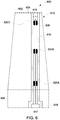
- Figure 6 illustrates another example embodiment of a blade assembly 600.
- the blade assembly 600 may include the blade of Figures 2-3 . Similar to the example embodiment of Figures 4-5 , the blade assembly 600 of Figure 6 may include an airfoil 602 that extends from a distal tip 604 to a platform 606.
- the airfoil 602 may be comprised of a housing 608 that includes a hollow interior 610 that extends from the distil tip 604 to the platform 606. Disposed within the hollow interior may be a turbine damper 612 for dampening vibrations of the blade assembly 600.
- energy instead of friction based energy dissipation, energy may be dissipated through impact between dampening masses and the housing, or internal walls of the blade.
- the turbine damper 612 in the example of Figure 6 may include and elongated body 614 that extends within the housing 608 from a distal end 616 to a base 617 at a platform end 618.
- the elongated body 614 may be elongated along a radial direction of the turbine blade relative to a rotation axis of the turbine blade.
- the elongated body 614 may be a rod, stick, pole, shaft, etc.
- the elongated body 614 in the example embodiment of Figure 6 includes plural dampening masses 620A, 620B, 620C that are secured thereto.
- the dampening masses may be fixed to the elongated body 614, may be of one piece construction with the elongated body 614, or the like such that the dampening masses 620A-C do not move in relation to the elongated body 614.
- the dampening masses 620A-C engage the housing 608 to transfer impact energy between the elongated body 614, dampening masses 620A-C, and housing 608.
- three dampening masses 620A-C may be provided, while in other examples only one dampening mass may be provided. Alternatively, more than five dampening masses or more may be provided.
- the dampening masses 620A-C are rigidly attached on the elongated body 614.
- the elongated body 614 can be either inserted in a separate housing and can be inserted in the blade, or the elongated body 614 can directly be inserted in the blade.
- the elongated body 614 and dampening masses 620A-C may be designed such that the natural frequency of the first few modes of the elongated body 614 covers the critical blade modes to be damped.
- the dampening masses may be sized to dampen different vibration modes of the turbine blade.
- a size of each of the dampening masses may be dictated based on the vibration mode experienced by the turbine blade at the location of the corresponding dampening mass.
- the elongated body 614 may also undergo vibratory motion and the dampening masses 620A-C impact the inner walls of the blade (or housing) creating impact damping.
- the turbine damper 612 may include plural elongated bodies, each to be used in a corresponding blade of a rotor.
- the turbine damper 612 include a first elongated body that is within a first blade, such as blade 124 of Figure 2 , and also include a second elongated body that is within a second blade, such as blade 124A of Figure 2 .
- the turbine damper 612 includes each elongated body disposed within a blade of a blade assembly 600 that provides damping for the blade assembly.
- a turbine damper that may result in larger, lighter gas turbine blades, including larger, lighter last stage blades.
- the turbine damper relies on friction or impact damping, which are proven damping technologies in turbomachinery.
- other damping assemblies may be eliminated that are exterior to the turbine blade and can reduce size and overall performance of the rotor assembly.
- a turbine damper may be provided that may include an elongated body sized to fit inside a turbine blade, the elongated body elongated along a radial direction of the turbine blade relative to a rotation axis of the turbine blade, and plural dampening masses coupled with the elongated body and disposed at different locations along the radial direction.
- the plural dampening masses may be one or more of sized to dampen different vibration modes of the turbine blade, or moveable relative to and along the elongated body in the radial direction.
- the dampening masses may be sized for frequency tuning or providing contact load to generate friction damping.
- a size of each of the dampening masses may be dictated based on the vibration mode experienced by the turbine blade at the location of the corresponding dampening mass, and each of the dampening masses may not move relative to the elongated body.
- the dampening masses may be annular bodies extending around the elongated body and moveable relative to and along the elongated body in the radial direction.
- the locations of the dampening masses may be first locations along the radial direction of the turbine blade, and may also include mass stops disposed inside the turbine blade at different second locations along the radial direction of the turbine blade.
- the mass stops may be positioned inside the turbine blade to engage the dampening masses and stop radial movement of the dampening masses along the radial direction.
- each of the mass stops may be positioned inside the turbine blade to engage a different dampening mass of the dampening masses and stop the radial movement of the different dampening mass of the dampening masses.
- the elongated body may be stepped in diameter such that different segments of the elongated body that encompass different portions of a length of the elongated body in the radial direction have different diameters.
- the annular bodies of the dampening masses may have differently sized holes such that the annular bodies fit over different segments of the elongated body.
- the dampening masses may be disposed closer to a radial inward end of the elongated body along the radial direction prior to rotation of the turbine blade around the rotation axis and the dampening masses may be disposed farther from the radial inward end of the elongated body along the radial direction during the rotation of the turbine blade around the rotation axis.
- a turbine damper may be provided that may include an elongated body that may be sized to fit inside a turbine blade, the elongated body elongated along a radial direction of the turbine blade relative to a rotation axis of the turbine blade, and plural dampening masses may be coupled with the elongated body and disposed at different locations along the radial direction, wherein the dampening masses are sized to dampen different vibration modes of the turbine blade.
- the dampening masses may be sized to dampen the different vibration modes of the turbine blade such that a size of each of the dampening masses may be dictated based on the vibration mode experienced by the turbine blade at the location of the corresponding dampening mass.
- the dampening masses may be fixed in position along the elongated body.
- the elongated body may be a first elongated body
- the dampening masses may be a first set of the dampening masses
- the turbine blade may be a first turbine blade.
- the turbine damper may also include a second elongated body that may be sized to fit inside a second turbine blade, the second elongated body elongated along a radial direction of the second turbine blade relative to a rotation axis of the second turbine blade.
- the turbine damper may also include plural second dampening masses coupled with the second elongated body and disposed at different locations along the radial direction of the second turbine blade.
- the second dampening masses may be one or more of (a) are disposed at the locations along the radial direction of the second turbine blade that differ from the locations of the first dampening masses along the radial direction of the first turbine blade or (b) have different sizes than the first dampening masses of the first turbine blade.
- a turbine damper may be provided that may include an elongated body that may be sized to fit inside a turbine blade, the elongated body elongated along a radial direction of the turbine blade relative to a rotation axis of the turbine blade, and plural dampening masses coupled with the elongated body and disposed at different locations along the radial direction, The dampening masses may be moveable relative to and along the elongated body in the radial direction.
- the dampening masses may be annular bodies extending around the elongated body and moveable relative to and along the elongated body in the radial direction.
- the locations of the dampening masses may be first locations along the radial direction of the turbine blade.
- the turbine damper may also include mass stops disposed inside the turbine blade at different second locations along the radial direction of the turbine blade, the mass stops positioned inside the turbine blade to engage the dampening masses and stop radial movement of the dampening masses along the radial direction.
- each of the mass stops may be positioned inside the turbine blade to engage a different dampening mass of the dampening masses and stop the radial movement of the different dampening mass of the dampening masses.
- the elongated body may be stepped in diameter such that different segments of the elongated body that encompass different portions of a length of the elongated body in the radial direction have different diameters.
- the annular bodies of the dampening masses may have differently sized holes such that the annular bodies fit over different segments of the elongated body.
- the dampening masses may be disposed closer to a radial inward end of the elongated body along the radial direction prior to rotation of the turbine blade around the rotation axis and the dampening masses are disposed farther from the radial inward end of the elongated body along the radial direction during the rotation of the turbine blade around the rotation axis.
Landscapes
- Engineering & Computer Science (AREA)
- Mechanical Engineering (AREA)
- General Engineering & Computer Science (AREA)
- Turbine Rotor Nozzle Sealing (AREA)
Abstract
Description
- This invention was made with government support under contract number DE-FE0031613 awarded by the Department of Energy. The government has certain rights in the invention.
- Embodiments of the subject matter described herein relate to dampening elongated bodies that reduce or eliminate vibrations of blades in rotor assemblies.
- Rotor assemblies are used in various systems, such as gas turbine engines and turbochargers. In a gas turbine engine, pressurized air that is produced in a compression system is mixed with fuel in a combustor and ignited, generating hot combustion gases which flow through one or more turbine stages. The turbine stages extract energy from the hot combustion gases for generating engine thrust to propel a vehicle (e.g., a train, an aircraft, a marine vessel, etc.) or to power a load, such as an electrical generator.
- The gas turbine includes a rotor assembly having a plurality of blades extending radially outward from a rotor disk. Large industrial gas turbine (IGT) blades are exposed to unsteady aerodynamic loading, causing the blades to vibrate. If these vibrations are not adequately damped, they may cause high cycle fatigue and premature failure in the blades. Of all the turbine stages, the last-stage blade (LSB) is the tallest and therefore is the most vibrationally challenged component of the turbine. Vibration damping methods for turbine blades include platform dampers, damping wires, shrouds etc. However, each method includes drawbacks.
- For example, platform dampers sit underneath the blade platform and are effective for medium and long shank blades which have motion at the blade platform. IGT aft-stage blades have short shanks to reduce the weight of the blade and in turn reduce the pull load on the rotor which renders platform dampers ineffective. Meanwhile, tip shrouds , and in particular part-span-shroud blades have a high contact load that may prevent the shroud contact surfaces from sliding and providing damping. While a second part span shroud may be added, the second part span shroud adds weight and may reduce performance of the rotor assembly.
- In an embodiment, a turbine damper may be provided that may include an elongated body sized to fit inside a turbine blade, the elongated body elongated along a radial direction of the turbine blade relative to a rotation axis of the turbine blade, and plural dampening masses coupled with the elongated body and disposed at different locations along the radial direction. The plural dampening masses may be one or more of sized to dampen different vibration modes of the turbine blade, or moveable relative to and along the elongated body in the radial direction.
- In another embodiment, a turbine damper may be provided that may include an elongated body that may be sized to fit inside a turbine blade, the elongated body elongated along a radial direction of the turbine blade relative to a rotation axis of the turbine blade, and plural dampening masses may be coupled with the elongated body and disposed at different locations along the radial direction, wherein the dampening masses are sized to dampen different vibration modes of the turbine blade.
- In another embodiment, a turbine damper may be provided that may include an elongated body that may be sized to fit inside a turbine blade, the elongated body elongated along a radial direction of the turbine blade relative to a rotation axis of the turbine blade, and plural dampening masses coupled with the elongated body and disposed at different locations along the radial direction, The dampening masses may be moveable relative to and along the elongated body in the radial direction.
- The subject matter described herein will be better understood from reading the following description of non-limiting embodiments, with reference to the attached drawings, wherein below:
-
Figure 1 shows a schematic view of a gas turbine engine system according to an embodiment which includes a compressor, a combustor, and a turbine; -
Figure 2 illustrates a portion of a rotor disk and a pair of blades of a rotor assembly according to one embodiment; -
Figure 3 is a perspective view of a blade of the rotor assembly according to an alternative embodiment; -
Figure 4 is a side plan view with hidden lines of a blade assembly according to one embodiment; -
Figure 5 is a side plan view with hidden lines of a blade assembly according to one embodiment; and -
Figure 6 is a side plan view with hidden lines of a blade assembly according to one embodiment. - One or more embodiments described herein provide turbine dampers for a rotor. The turbine dampers may be located within each blade of a blade assembly for a turbine and comprise an elongated body and dampening masses spaced along the elongated body. In some embodiments, the dampening masses may move in relation to the elongated body and move between mass stops also disposed within the blade. The mass stops may be secured to the elongated body or formed from a housing encasing the elongated body. The movable dampening masses function to provide friction dampening for the blade. Alternatively, the dampening masses may be fixed to the elongated body and not moveable along the elongated body. By being fixed to the elongated body, the dampening masses provide impact dampening within the blade. Thus, by providing the turbine dampers within each blade, tip shrouds used for dampening may be eliminated.
-
Figure 1 shows a schematic view of a gasturbine engine system 10 according to an embodiment which includes acompressor 15, acombustion system 25, and aturbine 40. The compressor and turbine may include rows of blades that are axially stacked in stages. Each stage includes a row of circumferentially spaced blades, which are fixed, and a row of rotor blades, which rotate about one or more central shafts. - In operation, the compressor rotor blades rotate about the shaft and, acting in concert with the stator blades, compress a flow of
air 20. The compression system delivers the compressed flow of air to a combustion system. Thecombustion system 25 mixes thecompressed flow 20 of air with a pressurized flow offuel 30 and ignites the mixture to provide a flow ofcombustion gases 35. The flow of combustion gases may be delivered to theturbine 40. The turbine rotor blades rotate about the shaft and, acting in concert with the stator blades, expand thecombustion gases 35 through theturbine 40 so as to produce mechanical work. The mechanical work produced in theturbine 40 drives thecompression system 15 via one ormore shafts 45 and may drive anexternal load 50, such as an electrical generator or the like, via one ormore shafts 46. The gasturbine engine system 10 may have different shaft, compressor, and turbine configurations and use other types of components in other embodiments. Other types of turbines may also be used. - The embodiments of the rotor assembly described herein may be used in the gas
turbine engine system 10, such as on theturbine 40 or thecompressor 15. However, the embodiments of the rotor assembly described herein are not limited to use in theengine system 10 shown inFigure 1 , and may be used in other devices, such as turbochargers, HVAC systems, and the like. -
Figure 2 illustrates a portion of arotor disk 133 and a pair ofblades rotor assembly 122 of a turbine according to one embodiment. In one example, the turbine is the turbine illustrated inFigure 1 . Eachblade Figures 4-6 . Although not shown, therotor disk 133 has a curved outer periphery, and therotor assembly 122 further includesadditional blades 124 extending radially from therotor disk 133 at spaced apart locations along the outer periphery of therotor disk 133. Theblades 124 havemounting segments 208 that mount to therotor disk 133,airfoils 200 that extend from therotor disk 133, and optionally also includeplatforms 206 disposed between theairfoil 200 and themounting segment 208. Theplatforms 206 extend laterally outward from thecorresponding blades 124 towards at least one neighboring (e.g., immediately adjacent)blade 124. Themounting segments 208 are received incorresponding support slots 210 of therotor disk 133 to mount theblades 124. Themounting segments 208 may be referred to herein asdovetails 208 due to the shapes of themounting segments 208. Thesupport slots 210 have a complementary shape to thedovetails 208. - The
airfoils 200 extend from theplatforms 206 todistal tips 204 of theairfoils 200. Theairfoils 200 receive energy from the gas (e.g., air, exhaust, or the like) flowing through therotor assembly 122. Theblades 124 may have a pair of first andsecond shrouds airfoil 200. Theshrouds airfoil 200 between theplatform 206 and thedistal tip 204. In the illustrated embodiment, theshrouds medial region 220 of theairfoil 200 that is spaced apart from thedistal tip 204 and theplatform 206. In an alternative embodiment, theshrouds distal tips 204 of theairfoils 200. In another alternative embodiment, theblades 124 may include both mid-span shrouds and tip shrouds (Figure 3 ). The first andsecond shrouds respective airfoil 200. For example, thefirst shroud 216 may extend from a first side (e.g., a pressure side) of theairfoil 200, and thesecond shroud 218 extends from an opposite second side (e.g., a suction side) of theairfoil 200. When therotor assembly 122 is fully assembled, theshrouds blades 124 extend circumferentially and define a shroud ring that is concentric with therotor disc 133. Theshrouds airfoil 200 todistal ends 224 that are remote from theairfoil 200. Thedistal end 224 of thefirst shroud 216 of afirst blade 124A is disposed at least proximate to thedistal end 224 of thesecond shroud 218 of a neighboring,second blade 124B. -
Figure 3 is a perspective view of a blade of the rotor assembly (shown inFigure 2 ) according to an alternative embodiment. The airfoil of the blade extends from the platform to the distal tip. The airfoil includes a first set 302 of mid-span shrouds and a second set 304 of tip shrouds. The first set of mid-span shrouds includemid-span shrouds carrier shroud 216B and alid shroud 218B, which are located at thedistal tip 204. Therefore, in some example embodiments, the blade may include multiple sets of shrouds. -
Figure 4 illustrates ablade assembly 400 that includes anairfoil 402 that represents a blade. In one example, theblade assembly 400 may include the blade ofFigures 2-3 . Theairfoil 402 extends from adistal tip 404 to aplatform 406. Theairfoil 402 may be comprised of a housing 408 that includes ahollow interior 410 that extends from thedistil tip 404 to theplatform 406. When used herein, the housing 408 may refer to both the wall of the air foil itself, or to a separate structure that is within the airfoil and contains aturbine damper 412. In this example embodiment, the housing 408 is the airfoil orblade interior 410. Specifically, disposed within the hollow interior of the housing 408 may be theturbine damper 412 for dampening vibrations of theblade assembly 400. - The
turbine damper 412 in the example ofFigure 4 may include anelongated body 414 that extends within the housing 408 from thedistal tip 404 to theplatform 406. In particular, theelongated body 414 may be elongated along a radial direction of the turbine blade relative to a rotation axis of the turbine blade. Theelongated body 414 may be a rod, stick, pole, shaft, etc. Theelongated body 414 may have a circular cross-section, square cross-section, a rectangular cross-section, a triangular cross-section, be frustoconical, have a tapering or variable cross-section, a combination of any of the previous cross-sections described, or the like. In one example, theelongated body 414 engages thedistal tip 404 andplatform 406 to frictionally fit within the housing. In another example, theelongated body 414 may be removably coupled to thedistal tip 404 and/orplatform 406 through a fastener, compression fit, or the like. Alternatively, theelongated body 414 is of one-piece construction being integrally formed with the housing 408. In yet another example, theelongated body 414 couples to thedistal tip 404 and/orplatform 406, while alternatively, theelongated body 414 merely extends adjacent thedistal tip 404 and/orplatform 406, but does not couple to thedistal tip 404 and/orplatform 406, instead coupling to a sidewall of a housing 408. - The
elongated body 414 extends from adistal end 416 to a base 417 at aplatform end 418. Theelongated body 414 receives plural dampeningmasses elongated body 414 includes afirst portion 426 having a first diameter or width and asecond portion 428 extending therefrom that has a second diameter or width that is less than the first diameter or width. As a result, a first steppedsurface 430A is formed between thefirst portion 426 andsecond portion 428. In an example, when thefirst portion 426 andsecond portion 428 both have circular cross-sections, the first steppedsurface 430A is an annular surface that may engage the annular surface of a corresponding first dampeningmass 420A. The first dampening mass may then be moveable to, or alternatively may engage the firstmass stop 422A. Alternatively, thefirst portion 526 may have a square cross-surface and the first steppedsurface 430A may be a flange extending from the second portion and engage a flanged surface of the first dampeningmass 420A. Specifically, the shape of the first portion, second portion, and dampening mass may be varied based on facilitating manufacturing, manufacturing costs, increasing surface area engagement between the first dampeningmass 420A and the first steppedsurface 430A or firstmass stop 422A, or the like. - The
elongated body 414 may also include athird portion 432 having a third diameter or width that extends from thesecond portion 428, where the third diameter or width may be less than the second diameter or width of thesecond portion 428. In this manner, a second steppedsurface 430B may be formed similar to the first steppedsurface 430A. The second steppedsurface 430B may be of size and shape as described in relation to the first steppedsurface 430A. To this end, the second steppedsurface 430B may engage the second dampeningmass 420B that engages the secondmass stop 422B. In particular, the secondmass stop 422B may be of size and shape to accommodate the second dampeningmass 420B. In a similar manner, afourth portion 434 may extend from thethird portion 432 of the elongated body to form a third steppedsurface 430C that engages the third dampeningmass 420C. The third dampeningmass 420C then is moveable to, or engages the thirdmass stop 422C similar to other dampening masses and mass stops described herein. - In the example of
Figure 4 , theplural dampening masses 420A-C movably surround theelongated body 414 to move in relation to theelongated body 414. As an example, when theelongated body 414 has a circular cross section, each of theplural dampening masses 420A-C may be annular bodies, or doughnut shaped with a centrally located opening, or hole with a diameter that may be slightly larger than the diameter of theelongated body 414. While three dampeningmasses 420A-C are illustrated in the example embodiment ofFigure 4 , in other example embodiments more or less dampening masses may be utilized. - In the example embodiment of
Figure 4 , each of theplural dampening masses 420A-C has a corresponding mass stop 422A-C. Each corresponding mass stop 422A-C may be configured to prevent movement of theplural masses 420A-C relative to theelongated body 414. The plural mass stops 422A-C may be secured to theelongated body 414, be of one-piece construction with the elongated body, secured to the housing 408, be of one-piece construction with the housing 408, coupled to an intermediary structure secured to the housing, etc. In each example, similar to the elongated body, the plural mass stops 422A-C do not move relative to the housing. Alternatively, the elongated body may move relative to the housing, where the plural mass stops 422A-C do not move relative to theelongated body 414, or do move relative to the elongated body, but not relative to the housing 408. In example embodiments, there are the same number of plural mass stops 422A-C asplural masses 420A-C. In other embodiments, the number of plural mass stops 422A-C differs from the plural masses 420AC. Specifically, in some embodiments, thedistal tip 404 orplatform 406 may function as a mass stop without providing a separate mass stop accordingly. To this end, only a single mass stop may be provided for three separate masses. In such an embodiment, thedistal tip 404 and/orplatform 406 may be considered as mass stops as described herein. - Each mass stop 422A-C defines a
movement path 424A-C for each mass 420A-C. The movement path is the path along theelongated body 414 each mass 420A-C moves. In particular, as the rotor rotates below a threshold speed, gravity overcomes the radial forces on each mass 420A-C such that each mass 420A-C remains in a first location of a movement path that positions each mass 420A-C closest to theplatform 406, or results in movement of the mass 420A-C towards the platform. Once above the threshold radial force, the plural masses overcome gravity and frictional forces and begin moving radially away from theplatform 406 toward thedistal tip 404 until each mass 420A-C reaches a second location when each mass is closest to thedistal tip 404. Specifically, each mass engages amass stop 422A-C and is held against the mass stop 422A-C to provide friction damping until the rotation of the rotor slows and the speed of the rotor again falls below the threshold speed. In this manner, the dampeningmasses 420A-C may be disposed closer to a radial inward end of theelongated body 414 along the radial direction prior to rotation of the turbine blade around the rotation axis and the dampeningmasses 420A-C may be disposed farther from the radial inward end of theelongated body 414 along the radial direction during the rotation of the turbine blade around the rotation axis. Thus, the contact loading provided is only from the centrifugal load instead of from another load, such as an interference fit, to ensure that the contact loading does not change over time. In particular, when an interference fit is used, deformation over time results in loading changes. By having only the centrifugal load, such loading changes do not occur, improving functionality. - Additionally, by providing
movable masses 420A-C, tuning of natural frequencies of theelongated body 414 andmasses 420A-C may be determined and used to cover the blade modes of interest of theblade assembly 400. In particular, when the blade rotates themovable masses 420A-C are pushed outboard due to centrifugal loading and load up against the mass stops 422A-C. Theelongated body 414 andmasses 420A-C are designed such that there are several damper natural modes covering the frequency range of the critical blade modes. So, as the blade undergoes a resonant crossing theelongated body 414 also vibrates and forces themasses 420A-C to move laterally and rub against the mass stops 422A-C creating friction damping. Thus, themasses 420A-C may be designed such that the natural frequencies of theelongated body 414 andmasses 420A-C cover the range of blade modes that need to be damped. When the blade vibrates, it excites theelongated body 414 and the attachedmasses 420A-C that dissipate energy either through impact or friction. - Specifically, in the example embodiment of
Figure 4 ,turbine damper 412 uses friction to provide the damping. In this embodiment, theplural masses 420A-C can be movable relative to and along theelongated body 414 in the radial direction, while the mass stops 422A-C can provide resting spots for the masses. Theelongated body 414 can either be inserted directly in the blade or be assembled inside a housing and the entire elongated body housing assembly can then be inserted in the blade. Features that act as radial stops 422A-C for themasses 420A-C can either be cast in the blade or be manufactured as a part of the housing. Consequently, energy may be dissipated through friction between the elongated body mounted dampeningmasses 420A-C and the mass stops 422A-C. - While in the example embodiment of
Figure 4 , only a single blade is illustrated, theturbine damper 412 may include plural elongated bodies, each to be used in a corresponding blade of a rotor. For example, in one example, theturbine damper 412 include a first elongated body that is within a first blade, such asblade 124 ofFigure 2 , and also include a second elongated body that is within a second blade, such asblade 124A ofFigure 2 . In particular, theturbine damper 412 includes each elongated body disposed within a blade of ablade assembly 400 that provides damping for the blade assembly. -
Figure 5 illustrates analternative blade assembly 500. In one example, theblade assembly 500 may include the blade ofFigures 2-3 . Similar to the example embodiment ofFigure 4 , theblade assembly 500 ofFigure 5 includes a friction based turbine damper. Similar to the blade assembly ofFigure 4 , theblade assembly 500 ofFigure 5 includes anairfoil 502 that extends from adistal tip 504 to aplatform 506. Theairfoil 502 may be comprised of ahousing 508 that includes ahollow interior 510 that extends from thedistil tip 504 to aplatform 506. In the example ofFigure 5 , aseparate housing 508 apart from the interior of the blade is illustrated. Disposed within the hollow interior may be aturbine damper 512 for dampening vibrations of theblade assembly 500. - The
turbine damper 512 in the example ofFigure 5 may include anelongated body 514 that extends within thehousing 508 from thedistal end 516 to a base 517 at aplatform end 518. In particular, theelongated body 514 may be elongated along a radial direction of the turbine blade relative to a rotation axis of the turbine blade. Theelongated body 514 may be a rod, stick, pole, shaft, etc. - The
elongated body 514 in the example embodiment ofFigure 5 has a variable diameter that receives theplural dampening masses housing 508 provides the plural mass stops 522A, 522B, 522C. Theplural dampening masses 520A-C may movably surround theelongated body 514 to move in relation to theelongated body 514. As an example, when theelongated body 514 has a circular cross section, each of theplural dampening masses 520A-C may be annular bodies, or doughnut shaped with a centrally located opening, or hole with a diameter that may be slightly larger than the diameter of theelongated body 514. In the example embodiment ofFigure 5 where theelongated body 514 includes varying stepped diameters, the dampeningmasses 520A-C may include varying hole diameters to accommodate the varying diameters of theelongated body 514. - By positioning the
masses 520A-C to provide friction surfaces perpendicular to the spanwise direction (e.g., in the chord-wise and/or circumferential directions) of the turbine blade, improved dampening is provided. Specifically,elongated body 514 ormasses 520A-C do not slide against spanwise-oriented blade surfaces such assurfaces 521A-C (e.g., in the spanwise-running inner wall of a blade channel oriented from dovetail/root to the blade tip). Instead, themasses 520A-C slide againstsurfaces 523A-C that are substantially perpendicular to the spanwise direction to provide the friction dampening. Thus, the contact loading betweenmasses 520A-C and surfaces 523A-C can vary as a function of rotor rotational speed. - In one example, the plural mass stops 522A-C are formed integrally within the
housing 508 as different steps that may include different diameters or widths that the masses can engage. In one example, the housing includes plural annular aligned bores, with each bore having a different diameter and forming amass stop surface - Meanwhile, the
elongated body 514 includes afirst portion 526 having a first diameter or width and asecond portion 528 extending therefrom that has a second diameter or width that is less than the first diameter or width. As a result, a first stepped surface 530A is formed between thefirst portion 526 andsecond portion 528. In an example, when thefirst portion 526 andsecond portion 528 both have circular cross-sections, the first stepped surface 530A is an annular surface that may engage the annular surface of a corresponding first dampeningmass 520A. The first dampening mass may then be moveable to, or alternatively may engage the firstmass stop 522A. Alternatively, thefirst portion 526 may have a square cross-surface and the first stepped surface 530A may be a flange extending from the second portion and engage a flanged surface of the first dampeningmass 520A. Specifically, the shape of the first portion, second portion, and dampening mass may be varied based on facilitating manufacturing, manufacturing costs, increasing surface area engagement between the first dampeningmass 520A and the first stepped surface 530A or firstmass stop 522A, or the like. - The
elongated body 514 may also include athird portion 532 having a third diameter or width that extends from thesecond portion 528, where the third diameter or width may be less than the second diameter or width of thesecond portion 528. In this manner, a second stepped surface 530B may be formed similar to the first stepped surface 530A. The second stepped surface 530B may be of size and shape as described in relation to the first stepped surface 530A. To this end, the second stepped surface 530B may engage the second dampeningmass 520B that engages the secondmass stop surface 523B of the secondmass stop 522B. In particular, the secondmass stop 522B may be formed in the housing similar to the firstmass stop 522A, and may be of size and shape to accommodate the second dampeningmass 520B. In a similar manner, afourth portion 534 may extend from thethird portion 532 of the elongated body to form a third stepped surface 530C that engages the third dampeningmass 520C. The third dampeningmass 520C then is moveable to, or engages the thirdmass stop surface 523C of the thirdmass stop 522C similar to other dampening masses and mass stops described herein. - Thus, the
turbine damper 512 includes anelongated body 514 on which several movable dampeningmasses 520A-C are mounted. Theelongated body 514 may be shaped in a stepped manner such that that each dampening mass 520A-C slides on an elongated body portion until a certain point. Similarly, stepped aligned bores with different sized sections may be machined on or in the blade or on or in ahousing 508 such that theelongated body 514 of theturbine damper 512 can be inserted all the way in the aligned bores and each dampening mass 520A-C may be prevented from sliding along theelongated body 514 by a stepped surface of theelongated mass 514 and a mass stop of thehousing 508. - When a blade including the
turbine damper 512 ofFigure 5 rotates, the dampeningmasses 520A-520C are pushed outboard due to centrifugal loading and they load up against the mass stops 522A-C. Theelongated body 514 and dampeningmasses 520A-C may be designed such that there are several damper natural modes covering the frequency range of the critical blade modes. So, as the blade undergoes a resonant crossing theelongated body 514 also vibrates and forces the dampeningmasses 520A-C to move laterally with theelongated body 514 to rub against each correspondingmass stop surface 523A-C of the housing, to create friction damping. For lower frequency modes theelongated body 514 may be expected to exhibit first flex motion and hence the dampeningmass 520A adjacent thedistal tip 504 is expected to provide the most damping. For higher order modes the other masses may also contribute significantly to the overall damping. In this manner, the dampeningmasses 520A-C may be sized for frequency tuning or may provide a contact load to generate friction damping. - While in the example embodiment of
Figure 5 , only a single blade is illustrated, theturbine damper 512 may include plural elongated bodies, each to be used in a corresponding blade of a rotor. For example, in one example, theturbine damper 512 include a first elongated body that is within a first blade, such asblade 124 ofFigure 2 , and also include a second elongated body that is within a second blade, such asblade 124A ofFigure 2 . In particular, theturbine damper 512 includes each elongated body disposed within a blade of ablade assembly 500 that provides damping for the blade assembly. -
Figure 6 illustrates another example embodiment of ablade assembly 600. In one example, theblade assembly 600 may include the blade ofFigures 2-3 . Similar to the example embodiment ofFigures 4-5 , theblade assembly 600 ofFigure 6 may include anairfoil 602 that extends from adistal tip 604 to aplatform 606. Theairfoil 602 may be comprised of ahousing 608 that includes ahollow interior 610 that extends from thedistil tip 604 to theplatform 606. Disposed within the hollow interior may be aturbine damper 612 for dampening vibrations of theblade assembly 600. In this example embodiment, instead of friction based energy dissipation, energy may be dissipated through impact between dampening masses and the housing, or internal walls of the blade. - The
turbine damper 612 in the example ofFigure 6 may include and elongated body 614 that extends within thehousing 608 from adistal end 616 to a base 617 at aplatform end 618. In particular, the elongated body 614 may be elongated along a radial direction of the turbine blade relative to a rotation axis of the turbine blade. The elongated body 614 may be a rod, stick, pole, shaft, etc. - The elongated body 614 in the example embodiment of
Figure 6 includes plural dampeningmasses masses 620A-C do not move in relation to the elongated body 614. Instead, the dampeningmasses 620A-C engage thehousing 608 to transfer impact energy between the elongated body 614, dampeningmasses 620A-C, andhousing 608. In one example, three dampeningmasses 620A-C may be provided, while in other examples only one dampening mass may be provided. Alternatively, more than five dampening masses or more may be provided. - In the embodiment of
Figure 6 , the dampeningmasses 620A-C are rigidly attached on the elongated body 614. The elongated body 614 can be either inserted in a separate housing and can be inserted in the blade, or the elongated body 614 can directly be inserted in the blade. - The elongated body 614 and dampening
masses 620A-C may be designed such that the natural frequency of the first few modes of the elongated body 614 covers the critical blade modes to be damped. Specifically, the dampening masses may be sized to dampen different vibration modes of the turbine blade. Specifically, a size of each of the dampening masses may be dictated based on the vibration mode experienced by the turbine blade at the location of the corresponding dampening mass. When the blade vibrates, the elongated body 614 may also undergo vibratory motion and the dampeningmasses 620A-C impact the inner walls of the blade (or housing) creating impact damping. - While in the example embodiment of
Figure 6 , only a single blade is illustrated, theturbine damper 612 may include plural elongated bodies, each to be used in a corresponding blade of a rotor. For example, in one example, theturbine damper 612 include a first elongated body that is within a first blade, such asblade 124 ofFigure 2 , and also include a second elongated body that is within a second blade, such asblade 124A ofFigure 2 . In particular, theturbine damper 612 includes each elongated body disposed within a blade of ablade assembly 600 that provides damping for the blade assembly. - Thus, provided is a turbine damper that may result in larger, lighter gas turbine blades, including larger, lighter last stage blades. The turbine damper relies on friction or impact damping, which are proven damping technologies in turbomachinery. By using the internal turbine damper, other damping assemblies may be eliminated that are exterior to the turbine blade and can reduce size and overall performance of the rotor assembly.
- In one or more embodiments, a turbine damper may be provided that may include an elongated body sized to fit inside a turbine blade, the elongated body elongated along a radial direction of the turbine blade relative to a rotation axis of the turbine blade, and plural dampening masses coupled with the elongated body and disposed at different locations along the radial direction. The plural dampening masses may be one or more of sized to dampen different vibration modes of the turbine blade, or moveable relative to and along the elongated body in the radial direction.
- Optionally, the dampening masses may be sized for frequency tuning or providing contact load to generate friction damping.
- Optionally, a size of each of the dampening masses may be dictated based on the vibration mode experienced by the turbine blade at the location of the corresponding dampening mass, and each of the dampening masses may not move relative to the elongated body.
- Optionally, the dampening masses may be annular bodies extending around the elongated body and moveable relative to and along the elongated body in the radial direction.
- Optionally, the locations of the dampening masses may be first locations along the radial direction of the turbine blade, and may also include mass stops disposed inside the turbine blade at different second locations along the radial direction of the turbine blade. The mass stops may be positioned inside the turbine blade to engage the dampening masses and stop radial movement of the dampening masses along the radial direction.
- Optionally, each of the mass stops may be positioned inside the turbine blade to engage a different dampening mass of the dampening masses and stop the radial movement of the different dampening mass of the dampening masses.
- Optionally, the elongated body may be stepped in diameter such that different segments of the elongated body that encompass different portions of a length of the elongated body in the radial direction have different diameters.
- Optionally, the annular bodies of the dampening masses may have differently sized holes such that the annular bodies fit over different segments of the elongated body.
- Optionally, the dampening masses may be disposed closer to a radial inward end of the elongated body along the radial direction prior to rotation of the turbine blade around the rotation axis and the dampening masses may be disposed farther from the radial inward end of the elongated body along the radial direction during the rotation of the turbine blade around the rotation axis.
- In one or more embodiments, a turbine damper may be provided that may include an elongated body that may be sized to fit inside a turbine blade, the elongated body elongated along a radial direction of the turbine blade relative to a rotation axis of the turbine blade, and plural dampening masses may be coupled with the elongated body and disposed at different locations along the radial direction, wherein the dampening masses are sized to dampen different vibration modes of the turbine blade.
- Optionally, the dampening masses may be sized to dampen the different vibration modes of the turbine blade such that a size of each of the dampening masses may be dictated based on the vibration mode experienced by the turbine blade at the location of the corresponding dampening mass.
- Optionally, the dampening masses may be fixed in position along the elongated body.
- Optionally, the elongated body may be a first elongated body, the dampening masses may be a first set of the dampening masses, and the turbine blade may be a first turbine blade. The turbine damper may also include a second elongated body that may be sized to fit inside a second turbine blade, the second elongated body elongated along a radial direction of the second turbine blade relative to a rotation axis of the second turbine blade. The turbine damper may also include plural second dampening masses coupled with the second elongated body and disposed at different locations along the radial direction of the second turbine blade. The second dampening masses may be one or more of (a) are disposed at the locations along the radial direction of the second turbine blade that differ from the locations of the first dampening masses along the radial direction of the first turbine blade or (b) have different sizes than the first dampening masses of the first turbine blade.
- In one or more embodiment a turbine damper may be provided that may include an elongated body that may be sized to fit inside a turbine blade, the elongated body elongated along a radial direction of the turbine blade relative to a rotation axis of the turbine blade, and plural dampening masses coupled with the elongated body and disposed at different locations along the radial direction, The dampening masses may be moveable relative to and along the elongated body in the radial direction.
- Optionally, the dampening masses may be annular bodies extending around the elongated body and moveable relative to and along the elongated body in the radial direction.
- Optionally, the locations of the dampening masses may be first locations along the radial direction of the turbine blade. The turbine damper may also include mass stops disposed inside the turbine blade at different second locations along the radial direction of the turbine blade, the mass stops positioned inside the turbine blade to engage the dampening masses and stop radial movement of the dampening masses along the radial direction.
- Optionally, each of the mass stops may be positioned inside the turbine blade to engage a different dampening mass of the dampening masses and stop the radial movement of the different dampening mass of the dampening masses.
- Optionally, the elongated body may be stepped in diameter such that different segments of the elongated body that encompass different portions of a length of the elongated body in the radial direction have different diameters.
- Optionally, the annular bodies of the dampening masses may have differently sized holes such that the annular bodies fit over different segments of the elongated body.
- Optionally, the dampening masses may be disposed closer to a radial inward end of the elongated body along the radial direction prior to rotation of the turbine blade around the rotation axis and the dampening masses are disposed farther from the radial inward end of the elongated body along the radial direction during the rotation of the turbine blade around the rotation axis.
- It is to be understood that the above description is intended to be illustrative, and not restrictive. For example, the above-described embodiments (and/or aspects thereof) may be used in combination with each other. In addition, many modifications may be made to adapt a particular situation or material to the teachings of the inventive subject matter without departing from its scope. While the dimensions and types of materials described herein are intended to define the parameters of the inventive subject matter, they are by no means limiting and are exemplary embodiments. Many other embodiments will be apparent to one of ordinary skill in the art upon reviewing the above description. The scope of the inventive subject matter should, therefore, be determined with reference to the appended claims, along with the full scope of equivalents to which such claims are entitled. In the appended claims, the terms "including" and "in which" are used as the plain-English equivalents of the respective terms "comprising" and "wherein." Moreover, in the following claims, the terms "first," "second," and "third," etc. are used merely as labels, and are not intended to impose numerical requirements on their objects. Further, the limitations of the following claims are not written in means-plus-function format and are not intended to be interpreted based on 35 U.S.C. § 112(f), unless and until such claim limitations expressly use the phrase "means for" followed by a statement of function void of further structure.
- This written description uses examples to disclose several embodiments of the inventive subject matter and also to enable a person of ordinary skill in the art to practice the embodiments of the inventive subject matter, including making and using any devices or systems and performing any incorporated methods. The patentable scope of the inventive subject matter is defined by the claims, and may include other examples that occur to those of ordinary skill in the art. Such other examples are intended to be within the scope of the claims if they have structural elements that do not differ from the literal language of the claims, or if they include equivalent structural elements with insubstantial differences from the literal languages of the claims.
- The foregoing description of certain embodiments of the inventive subject matter will be better understood when read in conjunction with the appended drawings. The various embodiments are not limited to the arrangements and instrumentality shown in the drawings.
- As used herein, an element or step recited in the singular and proceeded with the word "a" or "an" should be understood as not excluding plural of said elements or steps, unless such exclusion is explicitly stated. Furthermore, references to "one embodiment" of the inventive subject matter are not intended to be interpreted as excluding the existence of additional embodiments that also incorporate the recited features. Moreover, unless explicitly stated to the contrary, embodiments "comprising," "including," or "having" an element or a plurality of elements having a particular property may include additional such elements not having that property.
Claims (12)
- A turbine damper (412) comprising:an elongated body (414) sized to fit inside a turbine blade (124), the elongated body (414) elongated along a radial direction of the turbine blade (124) relative to a rotation axis of the turbine blade (124); anddampening masses (420A-C) coupled with the elongated body (414) and disposed at different locations along the radial direction, wherein the dampening masses (420A-C) are one or more of:sized and positioned to dampen different vibration modes of the turbine blade (124), ormoveable relative to and along the elongated body (414) in the radial direction.
- The turbine damper (412) of claim 1, wherein the dampening masses (420A-C) are annular bodies extending around the elongated body (414) and moveable relative to and along the elongated body (414) in the radial direction.
- The turbine damper (412) of claim 1 or 2, wherein the locations of the dampening masses (420A-C) are first locations along the radial direction of the turbine blade (124), and further comprising:
mass stops (422A-C) disposed inside the turbine blade (124) at different second locations along the radial direction of the turbine blade (124), the mass stops (422A-C) positioned inside the turbine blade (124) to engage the dampening masses (420A-C) and stop radial movement of the dampening masses (420A-C) along the radial direction. - The turbine damper (412) of claim 3, wherein each of the mass stops (422A-C) is positioned inside the turbine blade (124) to engage a different dampening mass of the dampening masses (420A-C) and stop the radial movement of the different dampening mass of the dampening masses (420A-C).
- The turbine damper (412) of claim 2, wherein the elongated body (414) is stepped in diameter such that different segments (426, 428) of the elongated body (414) that encompass different portions of a length of the elongated body (414) in the radial direction have different diameters.
- The turbine damper (412) of claim 5, wherein the annular bodies of the dampening masses (420A-C) have differently sized holes such that the annular bodies fit over different segments (426, 428) of the elongated body (414).
- The turbine damper (412) of claim 1 or 2, wherein the dampening masses (420A-C) are disposed closer to a radial inward end of the elongated body (414) along the radial direction prior to rotation of the turbine blade (124) around the rotation axis, and the dampening masses (420A-C) are disposed farther from the radial inward end of the elongated body (414) along the radial direction during the rotation of the turbine blade (124) around the rotation axis.
- The turbine damper (412) of claim 1, wherein the dampening masses (420A-C) are sized for frequency tuning or providing contact load to generate friction damping.
- The turbine damper (412) of claim 8, wherein a size of each of the dampening masses (420A-C) is based in part on the vibration mode experienced by the turbine blade (124) at the location of the respective dampening mass.
- The turbine damper (412) of claim 8, wherein friction surfaces of the dampening masses (420A-C) are configured to be positioned perpendicular to a spanwise direction of the turbine blade (124).
- The turbine damper (412) of claim 1 or 2, wherein the dampening masses (420A-C) are fixed in position along the elongated body (414).
- The turbine damper (412) of claim1 or 2, wherein the elongated body (414) is a first elongated body (414), the dampening masses (420A-C) are a first set of the dampening masses, and the turbine blade (124) is a first turbine blade (124), and further comprising:a second elongated body (414) sized to fit inside a second turbine blade (124), the second elongated body (414) elongated along a radial direction of the second turbine blade (124) relative to a rotation axis of the second turbine blade (124); andsecond dampening masses (420A-C) coupled with the second elongated body (414) and disposed at different locations along the radial direction of the second turbine blade (124), wherein the second dampening masses (420A-C) one or more of (a) are disposed at the locations along the radial direction of the second turbine blade (124) that differ from the locations of the first dampening masses along the radial direction of the first turbine blade (124) or (b) have different sizes than the first dampening masses (420A-C) of the first turbine blade (124).
Applications Claiming Priority (1)
| Application Number | Priority Date | Filing Date | Title |
|---|---|---|---|
| US16/794,732 US11371358B2 (en) | 2020-02-19 | 2020-02-19 | Turbine damper |
Publications (2)
| Publication Number | Publication Date |
|---|---|
| EP3869009A1 true EP3869009A1 (en) | 2021-08-25 |
| EP3869009B1 EP3869009B1 (en) | 2024-04-03 |
Family
ID=73698538
Family Applications (1)
| Application Number | Title | Priority Date | Filing Date |
|---|---|---|---|
| EP20211380.9A Active EP3869009B1 (en) | 2020-02-19 | 2020-12-02 | Damper for a turbine blade |
Country Status (3)
| Country | Link |
|---|---|
| US (2) | US11371358B2 (en) |
| EP (1) | EP3869009B1 (en) |
| JP (1) | JP7706880B2 (en) |
Families Citing this family (13)
| Publication number | Priority date | Publication date | Assignee | Title |
|---|---|---|---|---|
| US11808166B1 (en) * | 2021-08-19 | 2023-11-07 | United States Of America As Represented By The Administrator Of Nasa | Additively manufactured bladed-disk having blades with integral tuned mass absorbers |
| US11572791B1 (en) | 2022-01-12 | 2023-02-07 | General Electric Company | Vibration damping system for turbine nozzle or blade using damper pins with wire mesh members 1HEREON |
| US11634991B1 (en) * | 2022-01-12 | 2023-04-25 | General Electric Company | Vibration damping system for turbine nozzle or blade using elongated body and wire mesh member |
| US11519276B1 (en) * | 2022-01-12 | 2022-12-06 | General Electric Company | Vibration damping system for turbine blade or nozzle, retention system therefor, and method of assembly |
| US12071862B2 (en) | 2022-07-27 | 2024-08-27 | Ge Infrastructure Technology Llc | Vibration damping system for turbine nozzle or blade using stacked plate members |
| US11976565B2 (en) | 2022-07-27 | 2024-05-07 | Ge Infrastructure Technology Llc | Nested damper pin and vibration dampening system for turbine nozzle or blade |
| US12276205B2 (en) | 2023-06-29 | 2025-04-15 | Ge Infrastructure Technology Llc | Damper element with flexible legs for vibration dampening system for turbine blade |
| US12134972B1 (en) * | 2023-06-29 | 2024-11-05 | Ge Infrastructure Technology Llc | Damper element with spring-suspended bearing member for vibration dampening system for turbine blade |
| US12006831B1 (en) | 2023-06-29 | 2024-06-11 | Ge Infrastructure Technology Llc | Damper element with spring-suspended bearing member for vibration dampening system for turbine blade |
| US12553349B2 (en) * | 2023-06-29 | 2026-02-17 | Ge Infrastructure Technology Llc | Vibration dampening system including resonant-tuned elongated body for damper element(s) for turbine component |
| US12421856B2 (en) | 2023-06-29 | 2025-09-23 | Ge Infrastructure Technology Llc | Damper element with flexible legs for vibration dampening system for turbine blade |
| US12371998B2 (en) | 2023-06-29 | 2025-07-29 | Ge Infrastructure Technology Llc | Nested damper pin and vibration dampening system for turbine nozzle or blade |
| US12371999B2 (en) * | 2023-12-29 | 2025-07-29 | Rtx Corporation | Damping system for an integrally bladed rotor |
Citations (5)
| Publication number | Priority date | Publication date | Assignee | Title |
|---|---|---|---|---|
| US3966357A (en) * | 1974-09-25 | 1976-06-29 | General Electric Company | Blade baffle damper |
| US6283707B1 (en) * | 1999-03-19 | 2001-09-04 | Rolls-Royce Plc | Aerofoil blade damper |
| EP2653657A2 (en) * | 2009-08-13 | 2013-10-23 | Siemens Energy, Inc. | Turbine blade having a constant thickness airfoil skin |
| US20130280045A1 (en) * | 2012-04-24 | 2013-10-24 | Gregory M. Dolansky | Airfoil including damper member |
| EP3097268A1 (en) * | 2014-01-24 | 2016-11-30 | United Technologies Corporation | Additive manufacturing process grown integrated torsional damper mechanism in gas turbine engine blade |
Family Cites Families (40)
| Publication number | Priority date | Publication date | Assignee | Title |
|---|---|---|---|---|
| US1833751A (en) * | 1929-07-05 | 1931-11-24 | Gen Electric | Vibration damping device |
| US2984453A (en) * | 1957-03-25 | 1961-05-16 | Westinghouse Electric Corp | Vibration damper for blading in elastic fluid apparatus |
| US2999669A (en) * | 1958-11-21 | 1961-09-12 | Westinghouse Electric Corp | Damping apparatus |
| US3240468A (en) * | 1964-12-28 | 1966-03-15 | Curtiss Wright Corp | Transpiration cooled blades for turbines, compressors, and the like |
| JPS5429201U (en) * | 1977-07-29 | 1979-02-26 | ||
| US4802823A (en) * | 1988-05-09 | 1989-02-07 | Avco Corporation | Stress relief support structures and assemblies |
| US5165860A (en) | 1991-05-20 | 1992-11-24 | United Technologies Corporation | Damped airfoil blade |
| US5232344A (en) | 1992-01-17 | 1993-08-03 | United Technologies Corporation | Internally damped blades |
| US5407321A (en) * | 1993-11-29 | 1995-04-18 | United Technologies Corporation | Damping means for hollow stator vane airfoils |
| US5558497A (en) | 1995-07-31 | 1996-09-24 | United Technologies Corporation | Airfoil vibration damping device |
| US5947688A (en) * | 1997-12-22 | 1999-09-07 | General Electric Company | Frequency tuned hybrid blade |
| US6033186A (en) * | 1999-04-16 | 2000-03-07 | General Electric Company | Frequency tuned hybrid blade |
| US6827551B1 (en) * | 2000-02-01 | 2004-12-07 | The United States Of America As Represented By The Administrator Of The National Aeronautics And Space Administration | Self-tuning impact damper for rotating blades |
| DE10301755A1 (en) * | 2003-01-18 | 2004-07-29 | Rolls-Royce Deutschland Ltd & Co Kg | Fan blade for a gas turbine engine |
| DE10356237A1 (en) | 2003-12-02 | 2005-06-30 | Alstom Technology Ltd | Damping arrangement for a blade of an axial turbine |
| US6929451B2 (en) | 2003-12-19 | 2005-08-16 | United Technologies Corporation | Cooled rotor blade with vibration damping device |
| US7125225B2 (en) | 2004-02-04 | 2006-10-24 | United Technologies Corporation | Cooled rotor blade with vibration damping device |
| US7217093B2 (en) | 2004-05-27 | 2007-05-15 | United Technologies Corporation | Rotor blade with a stick damper |
| US7413405B2 (en) | 2005-06-14 | 2008-08-19 | General Electric Company | Bipedal damper turbine blade |
| US7270517B2 (en) | 2005-10-06 | 2007-09-18 | Siemens Power Generation, Inc. | Turbine blade with vibration damper |
| US7736124B2 (en) | 2007-04-10 | 2010-06-15 | General Electric Company | Damper configured turbine blade |
| US7824158B2 (en) | 2007-06-25 | 2010-11-02 | General Electric Company | Bimaterial turbine blade damper |
| US8267662B2 (en) | 2007-12-13 | 2012-09-18 | General Electric Company | Monolithic and bi-metallic turbine blade dampers and method of manufacture |
| GB2468528B (en) * | 2009-03-13 | 2011-03-30 | Rolls Royce Plc | Vibration damper |
| US8579593B2 (en) | 2009-11-06 | 2013-11-12 | Siemens Energy, Inc. | Damping element for reducing the vibration of an airfoil |
| EP2568117A1 (en) * | 2011-09-06 | 2013-03-13 | ALSTOM Technology Ltd | Rotating element for a turbomachine with vibration damper, corresponding turbomachine and use of a liquid metal for a vibration damper |
| US8763360B2 (en) * | 2011-11-03 | 2014-07-01 | United Technologies Corporation | Hollow fan blade tuning using distinct filler materials |
| US9267380B2 (en) | 2012-04-24 | 2016-02-23 | United Technologies Corporation | Airfoil including loose damper |
| US9249668B2 (en) * | 2012-04-24 | 2016-02-02 | United Technologies Corporation | Airfoil with break-way, free-floating damper member |
| ES2546992T3 (en) * | 2012-10-24 | 2015-09-30 | MTU Aero Engines AG | Method for de-tuning the blades of a gas turbine engine |
| EP2971537B1 (en) * | 2013-03-15 | 2019-05-22 | United Technologies Corporation | Vibration damping for structural guide vanes |
| EP2806106A1 (en) | 2013-05-23 | 2014-11-26 | MTU Aero Engines GmbH | Blade of a turbomachine having an impulse body |
| US10316670B2 (en) * | 2013-12-05 | 2019-06-11 | United Technologies Corporation | Hollow blade having internal damper |
| US9879551B2 (en) * | 2014-05-22 | 2018-01-30 | United Technologies Corporation | Fluid damper and method of making |
| EP3018292B1 (en) * | 2014-11-10 | 2020-08-12 | Ansaldo Energia Switzerland AG | Turbine blade and corresponding gas turbine and manufacturing method |
| US10260372B2 (en) * | 2015-01-29 | 2019-04-16 | United Technologies Corporation | Vibration damping assembly and method of damping vibration in a gas turbine engine |
| EP3130757B1 (en) * | 2015-08-12 | 2018-07-04 | MTU Aero Engines GmbH | Bladed gas turbine rotor |
| US10442531B2 (en) * | 2015-08-18 | 2019-10-15 | Sikorsky Aircraft Corporation | Rotor damping |
| US20170130585A1 (en) * | 2015-11-09 | 2017-05-11 | General Electric Company | Airfoil with energy absorbing edge guard |
| US10287895B2 (en) * | 2015-12-28 | 2019-05-14 | General Electric Company | Midspan shrouded turbine rotor blades |
-
2020
- 2020-02-19 US US16/794,732 patent/US11371358B2/en active Active
- 2020-11-27 JP JP2020197055A patent/JP7706880B2/en active Active
- 2020-12-02 EP EP20211380.9A patent/EP3869009B1/en active Active
-
2022
- 2022-06-07 US US17/834,361 patent/US11773725B2/en active Active
Patent Citations (5)
| Publication number | Priority date | Publication date | Assignee | Title |
|---|---|---|---|---|
| US3966357A (en) * | 1974-09-25 | 1976-06-29 | General Electric Company | Blade baffle damper |
| US6283707B1 (en) * | 1999-03-19 | 2001-09-04 | Rolls-Royce Plc | Aerofoil blade damper |
| EP2653657A2 (en) * | 2009-08-13 | 2013-10-23 | Siemens Energy, Inc. | Turbine blade having a constant thickness airfoil skin |
| US20130280045A1 (en) * | 2012-04-24 | 2013-10-24 | Gregory M. Dolansky | Airfoil including damper member |
| EP3097268A1 (en) * | 2014-01-24 | 2016-11-30 | United Technologies Corporation | Additive manufacturing process grown integrated torsional damper mechanism in gas turbine engine blade |
Also Published As
| Publication number | Publication date |
|---|---|
| US11371358B2 (en) | 2022-06-28 |
| EP3869009B1 (en) | 2024-04-03 |
| US11773725B2 (en) | 2023-10-03 |
| JP7706880B2 (en) | 2025-07-14 |
| US20220307375A1 (en) | 2022-09-29 |
| JP2021131087A (en) | 2021-09-09 |
| US20210254478A1 (en) | 2021-08-19 |
Similar Documents
| Publication | Publication Date | Title |
|---|---|---|
| EP3869009B1 (en) | Damper for a turbine blade | |
| EP1250516B1 (en) | Turbine engine damper | |
| US8066479B2 (en) | Non-integral platform and damper for an airfoil | |
| US10648347B2 (en) | Damping inserts and methods for shrouded turbine blades | |
| US5407321A (en) | Damping means for hollow stator vane airfoils | |
| EP3112588A2 (en) | Rotor damper | |
| EP2412926B1 (en) | Hollow blade for a gas turbine | |
| CN112943376A (en) | Damper stack for a turbomachine rotor blade | |
| JP3177010B2 (en) | Rotor blade, rotor assembly for engine, and rotor blade modification method | |
| WO2014133649A2 (en) | Component retention with probe | |
| US11634991B1 (en) | Vibration damping system for turbine nozzle or blade using elongated body and wire mesh member | |
| WO2014158447A1 (en) | Fan blade dovetail and spacer | |
| US20030194324A1 (en) | Turbine blade assembly with pin dampers | |
| EP3901413B1 (en) | Blades having tip pockets | |
| Chakrabarti et al. | Turbine damper | |
| US20210108530A1 (en) | Vane seal system and seal therefor | |
| EP3957825B1 (en) | Turbine blade with friction and impact vibration damping elements | |
| WO2017146724A1 (en) | Damping for fabricated hollow turbine blades | |
| JP7599361B2 (en) | Turbine blades and turbines | |
| US10119410B2 (en) | Vane seal system having spring positively locating seal member in axial direction |
Legal Events
| Date | Code | Title | Description |
|---|---|---|---|
| PUAI | Public reference made under article 153(3) epc to a published international application that has entered the european phase |
Free format text: ORIGINAL CODE: 0009012 |
|
| STAA | Information on the status of an ep patent application or granted ep patent |
Free format text: STATUS: THE APPLICATION HAS BEEN PUBLISHED |
|
| AK | Designated contracting states |
Kind code of ref document: A1 Designated state(s): AL AT BE BG CH CY CZ DE DK EE ES FI FR GB GR HR HU IE IS IT LI LT LU LV MC MK MT NL NO PL PT RO RS SE SI SK SM TR |
|
| STAA | Information on the status of an ep patent application or granted ep patent |
Free format text: STATUS: REQUEST FOR EXAMINATION WAS MADE |
|
| 17P | Request for examination filed |
Effective date: 20220225 |
|
| RBV | Designated contracting states (corrected) |
Designated state(s): AL AT BE BG CH CY CZ DE DK EE ES FI FR GB GR HR HU IE IS IT LI LT LU LV MC MK MT NL NO PL PT RO RS SE SI SK SM TR |
|
| RIC1 | Information provided on ipc code assigned before grant |
Ipc: F01D 5/18 20060101ALN20231030BHEP Ipc: F01D 5/16 20060101AFI20231030BHEP |
|
| GRAP | Despatch of communication of intention to grant a patent |
Free format text: ORIGINAL CODE: EPIDOSNIGR1 |
|
| STAA | Information on the status of an ep patent application or granted ep patent |
Free format text: STATUS: GRANT OF PATENT IS INTENDED |
|
| RAP1 | Party data changed (applicant data changed or rights of an application transferred) |
Owner name: GENERAL ELECTRIC TECHNOLOGY GMBH |
|
| INTG | Intention to grant announced |
Effective date: 20231211 |
|
| GRAS | Grant fee paid |
Free format text: ORIGINAL CODE: EPIDOSNIGR3 |
|
| GRAA | (expected) grant |
Free format text: ORIGINAL CODE: 0009210 |
|
| STAA | Information on the status of an ep patent application or granted ep patent |
Free format text: STATUS: THE PATENT HAS BEEN GRANTED |
|
| AK | Designated contracting states |
Kind code of ref document: B1 Designated state(s): AL AT BE BG CH CY CZ DE DK EE ES FI FR GB GR HR HU IE IS IT LI LT LU LV MC MK MT NL NO PL PT RO RS SE SI SK SM TR |
|
| REG | Reference to a national code |
Ref country code: CH Ref legal event code: EP |
|
| REG | Reference to a national code |
Ref country code: DE Ref legal event code: R096 Ref document number: 602020028248 Country of ref document: DE |
|
| REG | Reference to a national code |
Ref country code: IE Ref legal event code: FG4D |
|
| REG | Reference to a national code |
Ref country code: LT Ref legal event code: MG9D |
|
| REG | Reference to a national code |
Ref country code: NL Ref legal event code: MP Effective date: 20240403 |
|
| REG | Reference to a national code |
Ref country code: AT Ref legal event code: MK05 Ref document number: 1672517 Country of ref document: AT Kind code of ref document: T Effective date: 20240403 |
|
| PG25 | Lapsed in a contracting state [announced via postgrant information from national office to epo] |
Ref country code: NL Free format text: LAPSE BECAUSE OF FAILURE TO SUBMIT A TRANSLATION OF THE DESCRIPTION OR TO PAY THE FEE WITHIN THE PRESCRIBED TIME-LIMIT Effective date: 20240403 |
|
| PG25 | Lapsed in a contracting state [announced via postgrant information from national office to epo] |
Ref country code: NL Free format text: LAPSE BECAUSE OF FAILURE TO SUBMIT A TRANSLATION OF THE DESCRIPTION OR TO PAY THE FEE WITHIN THE PRESCRIBED TIME-LIMIT Effective date: 20240403 |
|
| PG25 | Lapsed in a contracting state [announced via postgrant information from national office to epo] |
Ref country code: IS Free format text: LAPSE BECAUSE OF FAILURE TO SUBMIT A TRANSLATION OF THE DESCRIPTION OR TO PAY THE FEE WITHIN THE PRESCRIBED TIME-LIMIT Effective date: 20240803 |
|
| PG25 | Lapsed in a contracting state [announced via postgrant information from national office to epo] |
Ref country code: BG Free format text: LAPSE BECAUSE OF FAILURE TO SUBMIT A TRANSLATION OF THE DESCRIPTION OR TO PAY THE FEE WITHIN THE PRESCRIBED TIME-LIMIT Effective date: 20240403 |
|
| PG25 | Lapsed in a contracting state [announced via postgrant information from national office to epo] |
Ref country code: FI Free format text: LAPSE BECAUSE OF FAILURE TO SUBMIT A TRANSLATION OF THE DESCRIPTION OR TO PAY THE FEE WITHIN THE PRESCRIBED TIME-LIMIT Effective date: 20240403 Ref country code: HR Free format text: LAPSE BECAUSE OF FAILURE TO SUBMIT A TRANSLATION OF THE DESCRIPTION OR TO PAY THE FEE WITHIN THE PRESCRIBED TIME-LIMIT Effective date: 20240403 |
|
| PG25 | Lapsed in a contracting state [announced via postgrant information from national office to epo] |
Ref country code: GR Free format text: LAPSE BECAUSE OF FAILURE TO SUBMIT A TRANSLATION OF THE DESCRIPTION OR TO PAY THE FEE WITHIN THE PRESCRIBED TIME-LIMIT Effective date: 20240704 |
|
| PG25 | Lapsed in a contracting state [announced via postgrant information from national office to epo] |
Ref country code: PT Free format text: LAPSE BECAUSE OF FAILURE TO SUBMIT A TRANSLATION OF THE DESCRIPTION OR TO PAY THE FEE WITHIN THE PRESCRIBED TIME-LIMIT Effective date: 20240805 |
|
| PG25 | Lapsed in a contracting state [announced via postgrant information from national office to epo] |
Ref country code: ES Free format text: LAPSE BECAUSE OF FAILURE TO SUBMIT A TRANSLATION OF THE DESCRIPTION OR TO PAY THE FEE WITHIN THE PRESCRIBED TIME-LIMIT Effective date: 20240403 |
|
| PG25 | Lapsed in a contracting state [announced via postgrant information from national office to epo] |
Ref country code: CZ Free format text: LAPSE BECAUSE OF FAILURE TO SUBMIT A TRANSLATION OF THE DESCRIPTION OR TO PAY THE FEE WITHIN THE PRESCRIBED TIME-LIMIT Effective date: 20240403 |
|
| PG25 | Lapsed in a contracting state [announced via postgrant information from national office to epo] |
Ref country code: AT Free format text: LAPSE BECAUSE OF FAILURE TO SUBMIT A TRANSLATION OF THE DESCRIPTION OR TO PAY THE FEE WITHIN THE PRESCRIBED TIME-LIMIT Effective date: 20240403 |
|
| PG25 | Lapsed in a contracting state [announced via postgrant information from national office to epo] |
Ref country code: PL Free format text: LAPSE BECAUSE OF FAILURE TO SUBMIT A TRANSLATION OF THE DESCRIPTION OR TO PAY THE FEE WITHIN THE PRESCRIBED TIME-LIMIT Effective date: 20240403 |
|
| PG25 | Lapsed in a contracting state [announced via postgrant information from national office to epo] |
Ref country code: LV Free format text: LAPSE BECAUSE OF FAILURE TO SUBMIT A TRANSLATION OF THE DESCRIPTION OR TO PAY THE FEE WITHIN THE PRESCRIBED TIME-LIMIT Effective date: 20240403 |
|
| PG25 | Lapsed in a contracting state [announced via postgrant information from national office to epo] |
Ref country code: PT Free format text: LAPSE BECAUSE OF FAILURE TO SUBMIT A TRANSLATION OF THE DESCRIPTION OR TO PAY THE FEE WITHIN THE PRESCRIBED TIME-LIMIT Effective date: 20240805 Ref country code: PL Free format text: LAPSE BECAUSE OF FAILURE TO SUBMIT A TRANSLATION OF THE DESCRIPTION OR TO PAY THE FEE WITHIN THE PRESCRIBED TIME-LIMIT Effective date: 20240403 Ref country code: NO Free format text: LAPSE BECAUSE OF FAILURE TO SUBMIT A TRANSLATION OF THE DESCRIPTION OR TO PAY THE FEE WITHIN THE PRESCRIBED TIME-LIMIT Effective date: 20240703 Ref country code: LV Free format text: LAPSE BECAUSE OF FAILURE TO SUBMIT A TRANSLATION OF THE DESCRIPTION OR TO PAY THE FEE WITHIN THE PRESCRIBED TIME-LIMIT Effective date: 20240403 Ref country code: IS Free format text: LAPSE BECAUSE OF FAILURE TO SUBMIT A TRANSLATION OF THE DESCRIPTION OR TO PAY THE FEE WITHIN THE PRESCRIBED TIME-LIMIT Effective date: 20240803 Ref country code: HR Free format text: LAPSE BECAUSE OF FAILURE TO SUBMIT A TRANSLATION OF THE DESCRIPTION OR TO PAY THE FEE WITHIN THE PRESCRIBED TIME-LIMIT Effective date: 20240403 Ref country code: GR Free format text: LAPSE BECAUSE OF FAILURE TO SUBMIT A TRANSLATION OF THE DESCRIPTION OR TO PAY THE FEE WITHIN THE PRESCRIBED TIME-LIMIT Effective date: 20240704 Ref country code: FI Free format text: LAPSE BECAUSE OF FAILURE TO SUBMIT A TRANSLATION OF THE DESCRIPTION OR TO PAY THE FEE WITHIN THE PRESCRIBED TIME-LIMIT Effective date: 20240403 Ref country code: ES Free format text: LAPSE BECAUSE OF FAILURE TO SUBMIT A TRANSLATION OF THE DESCRIPTION OR TO PAY THE FEE WITHIN THE PRESCRIBED TIME-LIMIT Effective date: 20240403 Ref country code: CZ Free format text: LAPSE BECAUSE OF FAILURE TO SUBMIT A TRANSLATION OF THE DESCRIPTION OR TO PAY THE FEE WITHIN THE PRESCRIBED TIME-LIMIT Effective date: 20240403 Ref country code: BG Free format text: LAPSE BECAUSE OF FAILURE TO SUBMIT A TRANSLATION OF THE DESCRIPTION OR TO PAY THE FEE WITHIN THE PRESCRIBED TIME-LIMIT Effective date: 20240403 Ref country code: AT Free format text: LAPSE BECAUSE OF FAILURE TO SUBMIT A TRANSLATION OF THE DESCRIPTION OR TO PAY THE FEE WITHIN THE PRESCRIBED TIME-LIMIT Effective date: 20240403 Ref country code: RS Free format text: LAPSE BECAUSE OF FAILURE TO SUBMIT A TRANSLATION OF THE DESCRIPTION OR TO PAY THE FEE WITHIN THE PRESCRIBED TIME-LIMIT Effective date: 20240703 |
|
| REG | Reference to a national code |
Ref country code: DE Ref legal event code: R097 Ref document number: 602020028248 Country of ref document: DE |
|
| PG25 | Lapsed in a contracting state [announced via postgrant information from national office to epo] |
Ref country code: DK Free format text: LAPSE BECAUSE OF FAILURE TO SUBMIT A TRANSLATION OF THE DESCRIPTION OR TO PAY THE FEE WITHIN THE PRESCRIBED TIME-LIMIT Effective date: 20240403 |
|
| PG25 | Lapsed in a contracting state [announced via postgrant information from national office to epo] |
Ref country code: EE Free format text: LAPSE BECAUSE OF FAILURE TO SUBMIT A TRANSLATION OF THE DESCRIPTION OR TO PAY THE FEE WITHIN THE PRESCRIBED TIME-LIMIT Effective date: 20240403 |
|
| PG25 | Lapsed in a contracting state [announced via postgrant information from national office to epo] |
Ref country code: SK Free format text: LAPSE BECAUSE OF FAILURE TO SUBMIT A TRANSLATION OF THE DESCRIPTION OR TO PAY THE FEE WITHIN THE PRESCRIBED TIME-LIMIT Effective date: 20240403 Ref country code: RO Free format text: LAPSE BECAUSE OF FAILURE TO SUBMIT A TRANSLATION OF THE DESCRIPTION OR TO PAY THE FEE WITHIN THE PRESCRIBED TIME-LIMIT Effective date: 20240403 |
|
| PG25 | Lapsed in a contracting state [announced via postgrant information from national office to epo] |
Ref country code: SM Free format text: LAPSE BECAUSE OF FAILURE TO SUBMIT A TRANSLATION OF THE DESCRIPTION OR TO PAY THE FEE WITHIN THE PRESCRIBED TIME-LIMIT Effective date: 20240403 |
|
| PG25 | Lapsed in a contracting state [announced via postgrant information from national office to epo] |
Ref country code: SM Free format text: LAPSE BECAUSE OF FAILURE TO SUBMIT A TRANSLATION OF THE DESCRIPTION OR TO PAY THE FEE WITHIN THE PRESCRIBED TIME-LIMIT Effective date: 20240403 Ref country code: SK Free format text: LAPSE BECAUSE OF FAILURE TO SUBMIT A TRANSLATION OF THE DESCRIPTION OR TO PAY THE FEE WITHIN THE PRESCRIBED TIME-LIMIT Effective date: 20240403 Ref country code: RO Free format text: LAPSE BECAUSE OF FAILURE TO SUBMIT A TRANSLATION OF THE DESCRIPTION OR TO PAY THE FEE WITHIN THE PRESCRIBED TIME-LIMIT Effective date: 20240403 Ref country code: EE Free format text: LAPSE BECAUSE OF FAILURE TO SUBMIT A TRANSLATION OF THE DESCRIPTION OR TO PAY THE FEE WITHIN THE PRESCRIBED TIME-LIMIT Effective date: 20240403 Ref country code: DK Free format text: LAPSE BECAUSE OF FAILURE TO SUBMIT A TRANSLATION OF THE DESCRIPTION OR TO PAY THE FEE WITHIN THE PRESCRIBED TIME-LIMIT Effective date: 20240403 |
|
| PLBE | No opposition filed within time limit |
Free format text: ORIGINAL CODE: 0009261 |
|
| STAA | Information on the status of an ep patent application or granted ep patent |
Free format text: STATUS: NO OPPOSITION FILED WITHIN TIME LIMIT |
|
| 26N | No opposition filed |
Effective date: 20250106 |
|
| PG25 | Lapsed in a contracting state [announced via postgrant information from national office to epo] |
Ref country code: SI Free format text: LAPSE BECAUSE OF FAILURE TO SUBMIT A TRANSLATION OF THE DESCRIPTION OR TO PAY THE FEE WITHIN THE PRESCRIBED TIME-LIMIT Effective date: 20240403 |
|
| PG25 | Lapsed in a contracting state [announced via postgrant information from national office to epo] |
Ref country code: MC Free format text: LAPSE BECAUSE OF FAILURE TO SUBMIT A TRANSLATION OF THE DESCRIPTION OR TO PAY THE FEE WITHIN THE PRESCRIBED TIME-LIMIT Effective date: 20240403 |
|
| REG | Reference to a national code |
Ref country code: CH Ref legal event code: PL |
|
| PG25 | Lapsed in a contracting state [announced via postgrant information from national office to epo] |
Ref country code: LU Free format text: LAPSE BECAUSE OF NON-PAYMENT OF DUE FEES Effective date: 20241202 |
|
| PG25 | Lapsed in a contracting state [announced via postgrant information from national office to epo] |
Ref country code: SE Free format text: LAPSE BECAUSE OF FAILURE TO SUBMIT A TRANSLATION OF THE DESCRIPTION OR TO PAY THE FEE WITHIN THE PRESCRIBED TIME-LIMIT Effective date: 20240403 |
|
| REG | Reference to a national code |
Ref country code: BE Ref legal event code: MM Effective date: 20241231 |
|
| PG25 | Lapsed in a contracting state [announced via postgrant information from national office to epo] |
Ref country code: BE Free format text: LAPSE BECAUSE OF NON-PAYMENT OF DUE FEES Effective date: 20241231 |
|
| PG25 | Lapsed in a contracting state [announced via postgrant information from national office to epo] |
Ref country code: FR Free format text: LAPSE BECAUSE OF NON-PAYMENT OF DUE FEES Effective date: 20241231 |
|
| PG25 | Lapsed in a contracting state [announced via postgrant information from national office to epo] |
Ref country code: CH Free format text: LAPSE BECAUSE OF NON-PAYMENT OF DUE FEES Effective date: 20241231 |
|
| PG25 | Lapsed in a contracting state [announced via postgrant information from national office to epo] |
Ref country code: IE Free format text: LAPSE BECAUSE OF NON-PAYMENT OF DUE FEES Effective date: 20241202 |
|
| PGFP | Annual fee paid to national office [announced via postgrant information from national office to epo] |
Ref country code: DE Payment date: 20251126 Year of fee payment: 6 |
|
| PGFP | Annual fee paid to national office [announced via postgrant information from national office to epo] |
Ref country code: GB Payment date: 20251119 Year of fee payment: 6 |
|
| PG25 | Lapsed in a contracting state [announced via postgrant information from national office to epo] |
Ref country code: IT Free format text: LAPSE BECAUSE OF FAILURE TO SUBMIT A TRANSLATION OF THE DESCRIPTION OR TO PAY THE FEE WITHIN THE PRESCRIBED TIME-LIMIT Effective date: 20240403 |
|
| PG25 | Lapsed in a contracting state [announced via postgrant information from national office to epo] |
Ref country code: CY Free format text: LAPSE BECAUSE OF FAILURE TO SUBMIT A TRANSLATION OF THE DESCRIPTION OR TO PAY THE FEE WITHIN THE PRESCRIBED TIME-LIMIT; INVALID AB INITIO Effective date: 20201202 |