EP3868944A1 - Laundry treating apparatus - Google Patents
Laundry treating apparatus Download PDFInfo
- Publication number
- EP3868944A1 EP3868944A1 EP21157817.4A EP21157817A EP3868944A1 EP 3868944 A1 EP3868944 A1 EP 3868944A1 EP 21157817 A EP21157817 A EP 21157817A EP 3868944 A1 EP3868944 A1 EP 3868944A1
- Authority
- EP
- European Patent Office
- Prior art keywords
- opening
- extension portion
- detergent
- storage unit
- stopper
- Prior art date
- Legal status (The legal status is an assumption and is not a legal conclusion. Google has not performed a legal analysis and makes no representation as to the accuracy of the status listed.)
- Granted
Links
Images







Classifications
-
- D—TEXTILES; PAPER
- D06—TREATMENT OF TEXTILES OR THE LIKE; LAUNDERING; FLEXIBLE MATERIALS NOT OTHERWISE PROVIDED FOR
- D06F—LAUNDERING, DRYING, IRONING, PRESSING OR FOLDING TEXTILE ARTICLES
- D06F29/00—Combinations of a washing machine with other separate apparatus in a common frame or the like, e.g. with rinsing apparatus
- D06F29/005—Combinations of a washing machine with other separate apparatus in a common frame or the like, e.g. with rinsing apparatus the other separate apparatus being a drying appliance
-
- D—TEXTILES; PAPER
- D06—TREATMENT OF TEXTILES OR THE LIKE; LAUNDERING; FLEXIBLE MATERIALS NOT OTHERWISE PROVIDED FOR
- D06F—LAUNDERING, DRYING, IRONING, PRESSING OR FOLDING TEXTILE ARTICLES
- D06F39/00—Details of washing machines not specific to a single type of machines covered by groups D06F9/00 - D06F27/00
- D06F39/02—Devices for adding soap or other washing agents
-
- D—TEXTILES; PAPER
- D06—TREATMENT OF TEXTILES OR THE LIKE; LAUNDERING; FLEXIBLE MATERIALS NOT OTHERWISE PROVIDED FOR
- D06F—LAUNDERING, DRYING, IRONING, PRESSING OR FOLDING TEXTILE ARTICLES
- D06F39/00—Details of washing machines not specific to a single type of machines covered by groups D06F9/00 - D06F27/00
- D06F39/02—Devices for adding soap or other washing agents
- D06F39/022—Devices for adding soap or other washing agents in a liquid state
-
- D—TEXTILES; PAPER
- D06—TREATMENT OF TEXTILES OR THE LIKE; LAUNDERING; FLEXIBLE MATERIALS NOT OTHERWISE PROVIDED FOR
- D06F—LAUNDERING, DRYING, IRONING, PRESSING OR FOLDING TEXTILE ARTICLES
- D06F31/00—Washing installations comprising an assembly of several washing machines or washing units, e.g. continuous flow assemblies
-
- D—TEXTILES; PAPER
- D06—TREATMENT OF TEXTILES OR THE LIKE; LAUNDERING; FLEXIBLE MATERIALS NOT OTHERWISE PROVIDED FOR
- D06F—LAUNDERING, DRYING, IRONING, PRESSING OR FOLDING TEXTILE ARTICLES
- D06F34/00—Details of control systems for washing machines, washer-dryers or laundry dryers
- D06F34/28—Arrangements for program selection, e.g. control panels therefor; Arrangements for indicating program parameters, e.g. the selected program or its progress
- D06F34/34—Arrangements for program selection, e.g. control panels therefor; Arrangements for indicating program parameters, e.g. the selected program or its progress characterised by mounting or attachment features, e.g. detachable control panels or detachable display panels
-
- D—TEXTILES; PAPER
- D06—TREATMENT OF TEXTILES OR THE LIKE; LAUNDERING; FLEXIBLE MATERIALS NOT OTHERWISE PROVIDED FOR
- D06F—LAUNDERING, DRYING, IRONING, PRESSING OR FOLDING TEXTILE ARTICLES
- D06F35/00—Washing machines, apparatus, or methods not otherwise provided for
- D06F35/005—Methods for washing, rinsing or spin-drying
-
- D—TEXTILES; PAPER
- D06—TREATMENT OF TEXTILES OR THE LIKE; LAUNDERING; FLEXIBLE MATERIALS NOT OTHERWISE PROVIDED FOR
- D06F—LAUNDERING, DRYING, IRONING, PRESSING OR FOLDING TEXTILE ARTICLES
- D06F37/00—Details specific to washing machines covered by groups D06F21/00 - D06F25/00
- D06F37/26—Casings; Tubs
- D06F37/267—Tubs specially adapted for mounting thereto components or devices not provided for in preceding subgroups
-
- D—TEXTILES; PAPER
- D06—TREATMENT OF TEXTILES OR THE LIKE; LAUNDERING; FLEXIBLE MATERIALS NOT OTHERWISE PROVIDED FOR
- D06F—LAUNDERING, DRYING, IRONING, PRESSING OR FOLDING TEXTILE ARTICLES
- D06F39/00—Details of washing machines not specific to a single type of machines covered by groups D06F9/00 - D06F27/00
- D06F39/08—Liquid supply or discharge arrangements
- D06F39/083—Liquid discharge or recirculation arrangements
-
- D—TEXTILES; PAPER
- D06—TREATMENT OF TEXTILES OR THE LIKE; LAUNDERING; FLEXIBLE MATERIALS NOT OTHERWISE PROVIDED FOR
- D06F—LAUNDERING, DRYING, IRONING, PRESSING OR FOLDING TEXTILE ARTICLES
- D06F39/00—Details of washing machines not specific to a single type of machines covered by groups D06F9/00 - D06F27/00
- D06F39/12—Casings; Tubs
-
- D—TEXTILES; PAPER
- D06—TREATMENT OF TEXTILES OR THE LIKE; LAUNDERING; FLEXIBLE MATERIALS NOT OTHERWISE PROVIDED FOR
- D06F—LAUNDERING, DRYING, IRONING, PRESSING OR FOLDING TEXTILE ARTICLES
- D06F25/00—Washing machines with receptacles, e.g. perforated, having a rotary movement, e.g. oscillatory movement, the receptacle serving both for washing and for centrifugally separating water from the laundry and having further drying means, e.g. using hot air
Definitions
- the present disclosure relates to a laundry treating apparatus, and more specifically, relates to a laundry treating apparatus having a detergent supply.
- the laundry treating apparatus receives laundry including clothes, bedding, etc. inside a drum and removes contaminations from the laundry.
- the laundry treating apparatus may perform processes such as washing, rinsing, spinning and drying.
- the laundry treating apparatus may be classified into a top loading scheme apparatus and a front loading front scheme apparatus based on a scheme in which laundry is injected into the drum.
- the laundry treating apparatus may include a cabinet defining an appearance, a tub accommodated inside the cabinet, a drum that is rotatably mounted inside the tub, and into which laundry is injected, and a detergent supply that supplies detergent into the drum.
- the detergent supply has a detergent supply function to improve the washing effect.
- detergent refers to substances that enhance the washing effect, such as fabric detergent, fabric softener and fabric bleach.
- Detergent may be used in a powder form and a liquid form.
- Korean Patent Application Publication No. 10-2018-0090003 A1 discloses a detergent supply included in a laundry treating apparatus. In the laundry treating apparatus, a user may retract or extend a detergent storage unit of the detergent supply into or from the cabinet.
- the detergent storage unit may enter or drawn out through a detergent opening of the cabinet.
- corrosion of the portion of the cabinet may occur, resulting in reduced durability. Damage such as scratches may occur on a surface of the detergent storage unit due to edges of the cabinet around the detergent opening.
- Implementations of the present disclosure are intended to provide a laundry treating apparatus that may effectively suppress corrosion or deformation of the cabinet and improve durability thereof.
- implementations of the present disclosure are intended to provide a laundry treating apparatus that has excellent structural stability, improved coupling stability, and efficient arrangement between components.
- implementations of the present disclosure are intended to provide a laundry treating apparatus that may effectively improve utility of the detergent storage unit.
- the laundry treating apparatus may include a protective casing to prevent corrosion or durability degradation otherwise caused when detergent or washing water is discharged onto a portion of the cabinet around the detergent opening defined in a front panel when a drawer type detergent storage unit extends or retracts from or into the cabinet through the detergent opening.
- a coating on an exposed portion of the front panel around the detergent opening may be peeled off due to corrosion resulting from leakage of the detergent from the detergent storage unit.
- a coupling structure wrapping the exposed portion of the front panel using an injection molded component may prevent detergent from contacting the portion of the front panel.
- the cabinet may include a stainless steel (STS) material.
- STS stainless steel
- the detergent opening may be defined in the cabinet by partially opening the cabinet. Thus, an inner face of the opening may be exposed to an outside and thus may be vulnerable to the corrosion.
- the protective casing coupled to an opening extension portion of the front panel may be a plastic injection-molded component.
- the protective casing may have a structure that covers the exposed inner face of the opening defined in the cabinet.
- the protective casing may be coupled to a rear face of the front panel of the cabinet in a hooked manner.
- a laundry treating apparatus comprising: a cabinet including a front panel having a detergent opening defined therein; a tub disposed inside the cabinet; a drum rotatably disposed inside the tub; and a detergent storage unit retracting into the cabinet through the detergent opening, wherein detergent to be supplied to the drum is stored in the detergent storage unit, wherein the front panel has an opening extension portion extending from a periphery of the detergent opening toward an inside of the cabinet, wherein the apparatus further comprises a protective casing disposed inside the cabinet and coupled to the opening extension portion, wherein the protective casing surrounds at least a portion of the detergent storage unit retracting into the cabinet through the detergent opening, wherein the protective casing includes an opening protection wall constructed to cover an inner face of the opening extension portion facing toward the detergent opening to protect the opening extension portion.
- the opening protection wall surrounds the detergent opening, and is located between the opening extension portion and the detergent storage unit to screen at least a portion of the inner face of the opening extension portion.
- the protective casing further includes an opening coupler disposed on an outer face of the opening protection wall facing toward the opening extension portion, wherein the opening extension portion is inserted into and coupled to the opening coupler in a front to rear direction.
- the opening coupler includes: an outward extension portion extending outwards from the outer face of the opening protection wall; and a frontward extension portion extending forwards from the outward extension portion and spaced apart from the opening protection wall, wherein the opening extension portion is inserted into a space between the opening protection wall and the frontward extension portion.
- a front end of the opening protection wall is located in front of a front end of the frontward extension portion.
- the opening protection wall extends so that a rear end thereof is located in rear of the opening extension portion and supports at least a portion of the detergent storage unit retracting into the cabinet.
- the opening protection wall includes an opening coupling protrusion protruding outwards from the outer face, wherein the opening extension portion includes a protrusion receiving portion into which the opening coupling protrusion is inserted.
- the opening coupling protrusion is located in front of a front end of the frontward extension portion.
- the opening extension portion includes: a first extension portion extending rearward from the front panel by a first length; and a second extension portion extending rearward from the front panel by a second length larger than the first length, wherein the protrusion receiving portion is defined in the second extension portion.
- the opening coupler includes: a first coupler portion into which the first extension portion is inserted; and a second coupler portion disposed in rear of the first extension portion, wherein the second extension portion is inserted into the second coupler portion.
- the outward extension portion of the second coupler portion has a separation opening defined therein, wherein the separation opening is disposed in rear of the opening coupling protrusion and exposes the second extension portion in a rear direction.
- a height of the outward extension portion of the second coupler portion in which the separation opening is defined is greater than a height of the outward extension portion of the first coupler portion.
- the opening protection wall further includes an assembly guide protrusion protruding outwards from the outer face, wherein the opening extension portion further include an assembly guide groove open in a rear direction, wherein the assembly guide protrusion is inserted into the assembly guide groove in a rear to front direction.
- the assembly guide protrusion extends forward from the outward extension portion, wherein a front end of the assembly guide protrusion protrudes frontwards of the frontward extension portion.
- the detergent storage unit has a handle on a front end thereof, wherein the opening protection wall extends so that a rear end thereof is located in rear of the opening extension portion and surrounds and supports the handle.
- the protective casing further includes a rear wall located in rear of the opening extension portion and connected to the opening protection wall, wherein the rear wall has a through-opening defined therein through which the detergent storage unit passes, wherein the handle of the detergent storage unit is supported forwards by the rear wall, while a rest portion of the detergent storage unit except for the handle retracts into the cabinet through the through-opening.
- a front face of the handle is coplanar with a front face of the front panel while the handle is in contact with the rear wall.
- the apparatus further comprises a supply casing disposed inside the cabinet, and in rear of the protective casing, wherein a front end of the supply casing is coupled to the rear wall of the protective casing, wherein the supply casing accommodates therein the detergent storage unit retracting into the cabinet.
- the rear wall includes an opening stopper protruding from an inner circumferential face of the through-opening toward the detergent storage unit, wherein the detergent storage unit further includes a stopper protrusion overlapping with the opening stopper in a front and rear direction, wherein during a drawn-out process of the detergent storage unit from the cabinet, the stopper protrusion contacts the opening stopper such that an extending distance of the detergent storage unit is limited.
- the apparatus further comprises an inner stopper disposed inside the cabinet, and protruding toward the detergent storage unit retracting into the cabinet, wherein the inner stopper is located in rear of the opening stopper, and is located in front of the stopper protrusion of the detergent storage unit retracting into the cabinet.
- the apparatus further comprises a dispenser disposed inside the cabinet, and located above the detergent storage unit, wherein the dispenser supplies washing-water to the detergent storage unit, and includes the inner stopper.
- the stopper protrusion is constructed to bypass the inner stopper in the front and rear direction and to contact the opening stopper during the drawn-out process of the detergent storage unit.
- the front panel and the opening extension portion are made of metal, and are integral with each other, wherein the opening protection wall is made of plastic.
- One implementation of the present disclosure may improve the utility of the detergent storage unit simply and effectively using the inner stopper and the opening stopper.
- One implementation of the present disclosure may effectively protect the opening extension portion using the protective casing including the opening protection wall made of plastic material and thus may effectively prevent damage to the detergent storage unit.
- the implementations of the present disclosure may provide the laundry treating apparatus that may effectively suppress corrosion or deformation of the cabinet and improve durability.
- implementations of the present disclosure may provide the laundry treating apparatus having excellent structural stability, improved coupling stability, and efficient arrangement between the components.
- implementations of the present disclosure may provide the laundry treating apparatus that may effectively improve the utility of the detergent storage unit.
- FIGS. For simplicity and clarity of illustration, elements in the FIGS. are not necessarily drawn to scale.
- the same reference numbers in different FIGS. denote the same or similar elements, and as such perform similar functionality.
- descriptions and details of well-known steps and elements are omitted for simplicity of the description.
- numerous specific details are set forth in order to provide a thorough understanding of the present disclosure. However, it will be understood that the present disclosure may be practiced without these specific details. In other instances, well-known methods, procedures, components, and circuits have not been described in detail so as not to unnecessarily obscure aspects of the present disclosure.
- first element or layer when a first element or layer is referred to as being present "on" a second element or layer, the first element may be disposed directly on the second element or may be disposed indirectly on the second element with a third element or layer being disposed between the first and second elements or layers. It will be understood that when an element or layer is referred to as being “connected to”, or “coupled to” another element or layer, it may be directly on, connected to, or coupled to the other element or layer, or one or more intervening elements or layers may be present. In addition, it will also be understood that when an element or layer is referred to as being “between” two elements or layers, it may be the only element or layer between the two elements or layers, or one or more intervening elements or layers may also be present.
- the term "and/or” includes any and all combinations of one or more of the associated listed items. Expression such as “at least one of” when preceding a list of elements may modify the entire list of elements and may not modify the individual elements of the list.
- FIG. 1 is a perspective view of a laundry treating apparatus 10 according to one implementation of the present disclosure.
- the laundry treating apparatus 10 may include a cabinet 100 including a front panel 110 having a detergent opening 120 defined therein, a tub 12 disposed inside the cabinet 100, and a drum 14 rotatably disposed inside the tub 12.
- the laundry treating apparatus 10 may include a washing machine in which laundry is inserted into a washing tub to perform washing, rinsing and dehydration of the laundry, or a dryer in which wet laundry is inserted to perform drying thereof.
- the laundry treating apparatus 10 may be classified into a top load scheme apparatus and a front load scheme apparatus.
- FIG. 1 shows the laundry treating apparatus 10 as the front load scheme apparatus. This is only for convenience of description. The present disclosure may be applied not only to the washing machine as the front load scheme apparatus, but also to the washing machine as the top load scheme apparatus.
- the laundry treating apparatus 10 includes the cabinet 100 that defines the appearance thereof.
- the cabinet 100 may have the front panel 110.
- a detergent opening 120 may be defined in the front panel 110.
- a detergent storage unit 300 which will be described later may retract or extend into or from the cabinet 100 through the detergent opening 120.
- the cabinet 100 may have a manipulator having a display that displays information on an operating state while receiving various control commands from the user.
- the manipulator may be disposed on the front panel 110 or a separate control panel.
- the cabinet 100 may have a door installed on the front panel 110.
- the door is pivotally disposed on the cabinet 100 to control entry and exit of the laundry into and from the drum 14.
- the cabinet 100 defines the appearance of the laundry treating apparatus 10.
- the cabinet 100 may have an inner space defined therein in which various components constituting the laundry treating apparatus 10 may be accommodated.
- the drum 14 may be installed to accommodate therein the laundry input through an laundry inlet.
- the cabinet 100 may receive the tub 12 containing washing-water, and the drum 14 that is rotatably disposed inside the tub 12 to accommodate laundry therein.
- a balancer to compensate for eccentricity caused by rotation may be installed at one side of the drum 14.
- the manipulator may include various keys for controlling the operation state of the laundry treating apparatus 10 and the display for displaying the operation state of the laundry treating apparatus 10.
- the door may include a transparent member such as a tempered glass so that the interior of the cabinet 100 or the drum 14 may be visually identified.
- the laundry treating apparatus 10 the detergent opening 120 may be defined in the front panel 110.
- the detergent storage unit 300 may retract into the cabinet 100 through the detergent opening 120.
- Detergent to be supplied to the drum 14 may be stored inside the detergent storage unit 300.
- a detergent supply may be disposed in rear of the opening and in the cabinet 100.
- the detergent storage unit 300 may define a portion of the detergent supply inside the cabinet 100.
- FIG. 1 shows an example in which the detergent opening 120 is opened frontwards in the front panel 110 of the cabinet 100.
- the detergent opening 120 may be located in a corner area at a front face of the cabinet 100, for example, on one side of a top portion of the front panel 110.
- the detergent supply may be located inside the cabinet 100 and in rear of the detergent opening 120.
- the detergent supply may include the detergent storage unit 300 that may store detergent therein, a dispenser 450 that is located above the detergent storage unit 300 and supplies water to the detergent storage unit 300, and a supply casing 400 that accommodates therein the detergent storage unit 300 retracting into the cabinet.
- the detergent supply serves to automatically supply the detergent stored in the detergent storage unit 300 into the drum 14 during the washing step.
- Detergent refers to a substance that may enhance the laundry effect of the laundry, and may include powder based or liquid based fabric detergent and fabric softener.
- FIG. 2 shows a stack-type laundry treating apparatus including lower and upper laundry treating apparatuses 10 and 20 according to one implementation of the present disclosure.
- the upper laundry treating apparatus 10 may be stacked on the lower laundry treating apparatus 20.
- the laundry treating apparatuses 10 and 20 may be stacked vertically and be coupled to each other.
- a control panel may be disposed between front panels 110 of the laundry treating apparatuses 10 and 20.
- the control panel may communicate a signal with the upper laundry treating apparatus 20 and/or the lower laundry treating apparatus 10, and may include a display that provides information on each of the laundry treating apparatuses10 and 20 and a manipulator for controlling each of the laundry treating apparatuses 10 and 20.
- a single control panel may be used to control or display operating states of the plurality of laundry treating apparatuses 10 and 20 together.
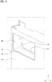
- FIG. 3 shows the front panel 110 of the cabinet 100 and a protective casing 200 coupled to the front panel 110 in the laundry treating apparatus 10 according to one implementation of the present disclosure.
- a side cross-section view of the protective casing 200 is shown in FIG. 3 .
- the protective casing 200 in FIG. 3 is spaced from the front panel 110.
- the laundry treating apparatus 10 may further include an opening extension portion 130 in the front panel 110.
- the protective casing 200 has an opening protection wall 210.
- the front panel 110 of the cabinet 100 may have the opening extension portion 130 defined therein that surrounds at least a portion of the detergent opening 120 and extends inwardly of the cabinet 100.
- the protective casing 200 is coupled to the opening extension portion 130 and is disposed inside the cabinet 100.
- the protective casing 200 may be constructed such that the detergent storage unit 300 passes through the protective casing 200.
- the protective casing 200 may include the opening protection wall 210 that has at least a portion covering an inner face of the opening extension portion 130 facing toward the detergent opening 120 to protect the opening extension portion 130.
- the opening extension portion 130 may extend rearward from the cabinet 100, and may be constructed to surround at least a portion of the detergent opening 120.
- the opening extension portion 130 may have a ring-shaped closed section extending along a perimeter of the detergent opening 120.
- the opening extension portion 130 may also have a circular ring shape surrounding the detergent opening 120.
- the opening extension portion 130 may also have a polygonal ring shape corresponding to the detergent opening 120.
- the opening extension portion 130 may be manufactured separately from the front panel 110 and then coupled to a rear face of the front panel 110 or may be integral with the front panel 110. When the opening extension portion 130 is integral with the front panel 110, the opening extension portion 130 may have a bent shape extending rearwards from the periphery of the detergent opening 120 of the front panel 110.
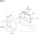
- FIG. 5 shows the opening extension portion 130 that extends rearwards from the periphery of the detergent opening 120 and defines a portion of the front panel 110 according to one implementation of the present disclosure.
- the protective casing 200 may be coupled to the opening extension portion 130 and may be disposed inside the cabinet 100.
- the protective casing 200 may be disposed on a rear face of the front panel 110 and coupled to the opening extension portion 130, and may have a ring-shaped cross section corresponding to a shape of the opening extension portion 130.
- the detergent storage unit 300 when the detergent storage unit 300 retracts into the cabinet 100 through the detergent opening 120, the detergent storage unit 300 passes through the opening extension portion 130 and the protective casing 200 and may retract into the cabinet 100.
- the detergent storage unit 300 may be constructed such that when the detergent storage unit 300 retracts into the cabinet 100, at least a portion thereof passes through a center of the protective casing 200 and is surrounded by the protective casing 200.
- the detergent opening 120 has an approximately rectangular cross section.
- the opening extension portion 130 may be embodied as a ring having an approximately rectangular cross section corresponding to that of the detergent opening 120.
- the protective casing 200 has an approximately rectangular ring cross section corresponding to that of the opening extension portion 130.
- the protective casing 200 may include the opening protection wall 210.
- the opening protection wall 210 may be constructed such that at least a portion of an outer face thereof away from the detergent opening 120 covers an inner face of the opening extension portion 130 facing toward the detergent opening 120.
- the opening protection wall 210 may be constructed to cover the opening extension portion 130 while being in direct contact with or spaced apart from an inner face of the opening extension portion 130 to prevent the opening extension portion 130 from being exposed to the outside.
- the opening protection wall 210 may have a ring shape extending in a front and rear direction X of the cabinet 100.
- the opening protection wall 210 may have a ring-shaped cross section having a diameter smaller than that of the opening extension portion 130.
- the protective casing 200 is constructed to be coupled to the opening extension portion 130, and to have the opening protection wall 210 covering the inner face of the opening extension portion 130, thus preventing the opening extension portion 130 from being exposed to the outside and protecting the opening extension portion 130.
- the laundry treating apparatus 10 may be a washing machine in which detergent and washing-water are used.
- the detergent storage unit 300 retracting or extending through the detergent opening 120 may contain detergent or water therein.
- the opening extension portion 130 surrounding the detergent opening 120 in which the detergent storage unit 300 is located may act as a frame that supports the detergent storage unit 300 or which is coupled to the detergent supply inside the cabinet 100 to secure rigidity to support the detergent supply.
- the opening extension portion 130 may be formed as a portion of the cabinet 100 during a forming process of the cabinet 100, and may be made of a metal material as in the cabinet 100. Accordingly, when water or detergent present in the detergent storage unit 300 comes into contact with the opening extension portion 130, corrosion of the opening extension portion 130 may occur.
- an outer face and an inner face of the opening extension portion 130 may be coated with a polymer, etc. as in the cabinet 100 such that a coating having corrosion resistance is formed thereon. Even when such a coating is formed, the coating may not protect a rear end of the opening extension portion 130 from corrosion due to a thickness and a manufacturing process of the front panel 110.
- the rear end of the opening extension portion 130 may have an edge toward the detergent opening 120. This edge may damage the outer surface of the detergent storage unit 300 during the retracting or drawn-out process of the detergent storage unit 300.
- one implementation of the present disclosure includes the protective casing 200 coupled to the opening extension portion 130, wherein the protective casing 200 has the opening protection wall 210 covering the inner face of the opening extension portion 130.
- the opening protection wall 210 covers the inner face of the opening extension portion 130 so that the opening extension portion 130 or the rear end of the opening extension portion 130 is not exposed.
- water or detergent that may be transferred from the detergent storage unit 300 may be effectively prevented from being in direct contact with the opening extension portion 130, which otherwise causes corrosion. Further, the damage to the outer surface of the detergent storage unit 300 by the opening extension portion 130 be effectively prevented.
- the opening protection wall 210 surrounds the detergent opening 120 and is located between the opening extension portion 130 and the detergent storage unit 300, and screens at least a portion of the inner face of the opening extension portion 130.
- one implementation of the present disclosure may have a structure in which the opening protection wall 210 and the opening extension portion 130 are sequentially stacked in a direction from a center of the detergent opening 120 to an outside as shown in FIG. 4 .
- the opening protection wall 210 may be constructed to screen an entirety of the opening extension portion 130 as shown in FIG. 3 or to screen at least a rear end of the opening extension portion 130.
- the front panel 110 may be made of a metal material
- the protective casing 200 may include a plastic material.
- the opening extension portion 130 may be made of a metal material, and the opening protection wall 210 of the protective casing 200 may be made of a plastic material.
- the opening extension portion 130 may be formed integrally with the front panel 110, and may be made of a metal material to secure the rigidity of the detergent supply or the supporting force of the detergent storage unit 300.
- the opening protection wall 210 may be made of a plastic material that has corrosion resistance so that the wall 210 is not corroded by water or detergent.
- the protective casing 200 or the opening protection wall 210 is made of a plastic material that may have corrosion resistance to prevent corrosion of the opening extension portion 130 which otherwise may occur due to water or detergent that may leak from the detergent storage unit 300.
- FIGS. 4 and 5 show an opening coupler 230 of the protective casing 200 to which the opening extension portion 130 is coupled.
- the protective casing 200 may further include the opening coupler 230.
- the opening coupler 230 is disposed on the outer face of the opening protection wall 210.
- the opening extension portion 130 is inserted in a front to rear direction and is coupled to the opening coupler 230.
- the opening coupler 230 may protrude from an outer face of the opening protection wall 210 facing toward an opposite side of the detergent opening 120 in a direction away from the detergent opening 120.
- the opening coupler 230 may have a ring shape extending in the circumferential direction of the detergent opening 120 along the circumference of the opening protection wall 210 and surrounding the detergent opening 120.
- the rear end of the opening extension portion 130 may be inserted into the opening coupler 230 in a front to rear direction.
- the opening protection wall 210 may move in a rear to front direction of the front panel 110 and may be inserted into the opening extension portion 130.
- the opening coupler 230 extending outwards from the outer face of the opening protection wall 210 and extending in the circumferential direction of the detergent opening 120 may be coupled to the opening extension portion 130, such that the protective casing 200 may be fixed to a rear side of the detergent opening 120 defined in the front panel 110.
- FIG. 4 shows the opening coupler 230 which the opening extension portion 130 inserted into and coupled to.
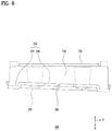
- FIG. 6 shows a top view of the protective casing 200 according to one implementation of the present disclosure.
- FIG. 7 shows a front view of the protective casing 200 according to one implementation of the present disclosure.
- the opening coupler 230 may include an outward extension portion 232 and a frontward extension portion 234.
- the outward extension portion 232 may extend outwards from the outer face of the opening protection wall 210.
- the frontward extension portion 234 may extend forwards from the outward extension portion 232 and may be spaced from the opening protection wall 210.
- the opening extension portion 130 may be inserted into between the opening protection wall 210 and the frontward extension portion 234.
- the outward extension portion 232 may protrude outwards from the outer face of the opening protection wall 210 and extend along the circumferential direction of the detergent opening 120. A height by which the outward extension portion 232 protrudes from the outer face of the opening protection wall 210 may vary as necessary.
- the frontward extension portion 234 may extend forwards from the outward extension portion 232.
- the frontward extension portion 234 may have a closed cross-section extending along the circumferential direction of the detergent opening 120. That is, the frontward extension portion 234 may have a sleeve shape spaced outwards from the opening protection wall 210.
- FIG. 4 shows a side cross-sectional view of the outward extension portion 232 and frontward extension portion 234.
- FIG. 6 shows that the frontward extension portion 234 is spaced from the opening protection wall 210 in a direction away from the detergent opening 120.
- FIG. 7 shows the outward extension portion 232 which protrudes outwards from the opening protection wall 210 and extends along the circumferential direction of the detergent opening 120.
- the frontward extension portion 234 may extend forwards from an end of the outward extension portion 232. That is, the frontward extension portion 234 may extend forwardly while being spaced apart from the opening protection wall 210 by the height by which the outward extension portion 232 protrudes.
- the opening extension portion 130 of the front panel 110 may be inserted into a space between the frontward extension portion 234 and the opening protection wall 210.
- the protrusion height of the outward extension portion 232 may be equal to or greater than a thickness of the opening extension portion 130.
- the frontward extension portion 234 may extend forwards while being spaced from the opening protection wall 210 via the outward extension portion 232, such that a space into which the opening extension portion 130 may be inserted in a front to rear direction may be defined between the frontward extension portion 234 and the opening protection wall 210.
- the opening extension portion 130 is inserted into the space by a length of the frontward extension portion 234 and is coupled to the opening coupler 230, thereby improving a coupling force therebetween.
- the opening protection wall 210 may extend so that a front end thereof is positioned in front of a front end of the frontward extension portion 234.
- the front end of the opening protection wall 210 may be located in front of the opening coupler 230 to increase an screening area of the opening extension portion 130, and may be positioned in front of a front end of the frontward extension portion 234 of the opening coupler 230.
- the front end of the opening protection wall 210 may be positioned adjacent to a front face of the front panel 110 or may be positioned in a parallel manner to the front face thereof.
- the frontward extension portion 234 extends forward from the outward extension portion 232.
- the front end of the frontward extension portion 234 may be located in rear of a rear face of the front panel 110.
- the protective casing 200 may include an opening coupling protrusion 250.
- the opening extension portion 130 may include a protrusion receiving portion 132 into which the opening coupling protrusion 250 is inserted.
- the opening coupling protrusion 250 may protrude outwards from the outer face of the opening protection wall 210.
- a shape of the opening coupling protrusion 250 may vary.
- a height by which the opening coupling protrusion 250 protrudes from the opening protection wall 210 may vary, and preferably, may be smaller than a height by which the outward extension portion 232 protrudes.
- FIGS. 6 and 7 show the opening coupling protrusion 250 protruding from the opening protection wall 210 and having a length extending along a perimeter of the protective casing 200 according to one implementation of the present disclosure.
- the opening extension portion 130 may have a protrusion receiving portion 132 into which the opening coupling protrusion 250 is inserted.
- the protrusion receiving portion 132 may be embodied as a groove into which the opening coupling protrusion 250 is inserted, or may be embodied as a hole through which the opening coupling protrusion 250 passes.
- FIG. 5 shows that the protrusion receiving portion 132 is embodied as a hole defined in the opening extension portion 130 according to one implementation of the present disclosure.
- the opening coupling protrusion 250 of the protective casing 200 may be inserted into the protrusion receiving portion 132 of the opening extension portion 130 while the opening extension portion 130 is inserted into the opening coupler 230. As the opening coupling protrusion 250 is inserted into and coupled to the protrusion receiving portion 132, the protective casing 200 may be prevented from moving in the front and rear direction X while the opening extension portion 130 is inserted into the opening coupler 230.
- the opening coupling protrusion 250 may be located in front of the front end of the frontward extension portion 234.
- the opening extension portion 130 may be pressed outwardly of the opening protection wall 210 by the opening coupling protrusion 250 until the opening coupling protrusion 250 is inserted into the protrusion receiving portion 132.
- the opening coupling protrusion 250 when the opening coupling protrusion 250 is located between the frontward extension portion 234 and the opening protection wall 210, that is, in rear of the front end of the frontward extension portion 234, the opening coupling protrusion 250 may not be easily inserted into or separated from the protrusion receiving portion 132 due to interference with the frontward extension portion 234, and the opening extension portion 130 may not be easily inserted into between the frontward extension portion 234 and the opening protection wall 210.
- the opening coupling protrusion 250 is positioned in front of the front end of the frontward extension portion 234 as shown in FIG. 6 .
- the opening extension portion 130 may be easily inserted into between the frontward extension portion 234 and the opening protection wall 210 and, at the same time, the opening coupling protrusion 250 may be easily inserted or separated into or from the protrusion receiving portion 132.
- the opening extension portion 130 may include a first extension portion 134 and a second extension portion 136.
- the first extension portion 134 may extend rearward from the front panel 110 by a first length.
- the second extension portion 136 may extend rearward from the front panel 110 by a second length longer than the first length.
- the protrusion receiving portion 132 may be defined in the second extension portion 136.
- first extension portion 134 and the second extension portion 136 may be constructed to be connected to each other and to extend along the circumferential direction of the detergent opening 120 and to surround the detergent opening 120. That is, the a portion of the opening extension portion 130 may define the first extension portion 134, and the other portion except for the first extension portion 134 may define the second extension portion 136 that extends by a larger length than that of the first extension portion 134.
- the second extension portion 136 may has the protrusion receiving portion 132 defined therein.
- a width of the protrusion receiving portion 132 in the front and rear direction X may be greater than a width of the opening coupling protrusion 250, and the second extension portion 136 should have the protrusion receiving portion 132 defined therein having a width larger than that of the opening coupling protrusion 250.
- the second extension portion 136 may extend by a larger length than that of the first extension portion 134 and may have a design margin to define the protrusion receiving portion 132 therein.
- a difference between the extending lengths of the first extension portion 134 and the second extension portion 136 may not be necessarily equal to the width of the protrusion receiving portion 132.
- the second extension portion 136 may extend from the first extension portion 134 by a smaller or larger length than the width of the protrusion receiving portion 132.
- each of the first extension portion 134 and the second extension portion 136 may vary as needed.
- the opening coupler 230 may include a first coupler portion 235 and a second coupler portion 236.
- the first extension portion 134 may be inserted into the first coupler portion 235.
- the second coupler portion 236 may be positioned in rear of the first extension portion 134.
- the second extension portion 136 may be inserted into the second coupler portion 236.
- the second extension portion 136 in which the protrusion receiving portion 132 is defined may extend by a larger length than that of the first extension portion 134. Positions of the first coupler portion 235 and the second coupler portion 236 may be adjusted based on the difference between the extending lengths of the first extension portion 134 and the second extension portion 136.
- the first coupler portion 235 and the second coupler portion 236 may be connected to each other and extend along the circumference of the protective casing 200. That is, a portion of the opening coupler 230 may define the first coupler portion 235, and a portion or an entirety of a remaining portion except for the first coupler portion 235 may define the second coupler portion 236.
- the first extension portion 134 may be inserted into the first coupler portion 235 in the front to rear direction.
- the second extension portion 136 may be inserted into the second coupler portion 236 in the front to rear direction.
- the second coupler portion 236 may be positioned in rear of the first coupler portion 235, such that the second extension portion 136 extending by a larger length than that of the first extension portion 134 may be inserted into the second coupler portion 236.
- the second coupler portion 236 may be connected to the first coupler portion 235 and may be located in rear of the first coupler portion 235.
- the frontward extension portion 234 of the second coupler portion 236 and the frontward extension portion 234 of the first coupler portion 235 may have the substantially same length.
- the outward extension portion 232 of the second coupler portion 236 may be located in rear of the outward extension portion 232 of the first coupler portion 235.
- the first coupler portion 235 may be constructed to overlap with the first extension portion 134 in the front and rear direction X, while the second coupler portion 236 may be constructed to overlap with the second extension portion 136 in the front and rear direction X. That is, the first coupler portion 235 may be constructed to face the first extension portion 134, while the second coupler portion 236 may be constructed to face the second extension portion 136.
- the second coupler portion 236 of the opening coupler 230 of the protective casing 200 is located in rear of the first coupler portion 235 thereof such that the second extension portion 136 of the opening extension portion 130 having the protrusion receiving portion 132 defined therein is longer than the first extension portion 134 thereof.
- the opening coupler 230 having a shape corresponding to a shape of the opening extension portion 130 may be formed, thereby improving coupling stability between the protective casing 200 and the opening extension portion 130.
- a separation opening 237 may be defined in the outward extension portion 232 of the second coupler portion 236.
- the separation opening 237 in rear of the opening coupling protrusion 250 may expose at least a portion of the second extension portion 136 in a rearward direction.
- the separation opening 237 may be positioned in rear of the opening coupling protrusion 250.
- a size of the separation opening 237 in a width direction of the protective casing 200 may be approximately equal to or greater than that of the opening coupling protrusion 250.
- the separation opening 237 may have a height from the outer face of the opening protection wall 210 equal to or greater than that of the opening coupling protrusion 250. However, the width and the height of the separation opening 237 may vary as needed.
- the separation opening 237 may be defined by opening at least a portion of the outward extension portion 232 of the second coupler portion 236.
- the separation opening 237 may be opened in the front and rear direction X.
- the separation opening 237 may include a portion of the outward extension portion 232 of the second coupler portion 236 that overlaps with the opening coupling protrusion 250 in the front and rear direction X.
- the protective casing 200 needs to be separated from the opening extension portion 130 of the front panel 110 for replacement, repair or other reasons.
- the separation opening 237 may be used so that the opening coupling protrusion 250 is easily separated from the protrusion receiving portion 132 of the opening extension portion 130.
- the user inserts a hand or tool into the separation opening 237 from a position in rear of the separation opening 237 and spaces the second extension portion 136 from the outer face of the opening protection wall 210.
- the second extension portion 136 which is spaced apart from the outer face of the opening protection wall 210 may be in a state in which the opening coupling protrusion 250 may be easily separated from the protrusion receiving portion 132. In this state, the user may move the protective casing 200 rearwardly and separate the casing 200 from the front panel 110.
- the user may use the separation opening 237 and then may easily separate a portion of the opening extension portion 130 where the protrusion receiving portion 132 is formed from the opening protection wall 210.
- the opening extension portion 130 may be easily pressed to a vertical level at which the protrusion receiving portion 132 deviates upwardly from the opening coupling protrusion 250.
- an extending height of the outward extension portion 232 having the separation opening 237 defined therein of the second coupler portion 236 may be greater than that of the outward extension portion 232 of the first coupler portion 235.
- a portion of the outward extension portion 232 where the separation opening 237 is defined may protrude to a higher level than the other portion thereof may protrude.
- the outward extension portion 232 of the second coupler portion 236 having the larger height than that of the outward extension portion 232 of the first coupler portion 235 may be formed along an entirety of the second coupler portion 236 or may be formed only at a portion of the second coupler portion 236where the separation opening 237 is defined.
- the portion of the outward extension portion 232 of the second coupler portion 236 where the separation opening 237 is formed should have a height than that of the outward extension portion 232 of the first coupler portion 235 to secure an area where the separation opening 237 may be formed.
- the outward extension portion 232 in which the separation opening 237 is formed has a larger height than that of a portion of the first coupler portion 235 or the second coupler portion 236 where the separation opening 237 is not formed, thereby securing an area in which the separation opening 237 may be formed.
- FIGS. 5 to 7 show an assembly guide protrusion 260 formed on the opening coupler 230 according to one implementation of the present disclosure.
- FIG. 8 shows that the assembly guide protrusion 260 of the protective casing 200 is inserted into an assembly guide groove 138 formed in the opening extension portion 130 according to one implementation of the present disclosure.
- the opening protection wall 210 further includes the assembly guide protrusion 260 protruding outwards from the outer face thereof.
- the opening extension portion 130 may further include the assembly guide groove 138 recessed in a rear end thereof in a front direction.
- the assembly guide protrusion 260 is inserted into the assembly guide groove 138 in a rear to front direction.
- the assembly guide protrusion 260 may protrude outwards from the outer face of the opening protection wall 210. That is, the assembly guide protrusion 260 may extend from the outer face of the opening protection wall 210 as an opposite face of the detergent opening 120 in a direction away from the detergent opening 120.
- the assembly guide groove 138 may be defined in a rear end of the opening extension portion 130 and may be opened rearwards. That is, the assembly guide groove 138 may be opened in a vertical direction Z, and a rear end thereof may be opened rearwards, and may have a shape extending forwards from the rear end.
- the assembly guide protrusion 260 may be inserted into the assembly guide groove 138 of the opening extension portion 130.
- the assembly guide protrusion 260 and the assembly guide groove 138 may allow the protective casing 200 to be in a normal state for assembly.
- each of the detergent opening 120, the opening extension portion 130 and the protective casing 200 is formed in a circular or rectangular shape, and even when the protective casing 200 rotates by a certain angle in the outer circumferential direction, it may be difficult for the user to visually identify the rotated state.
- width directional lengths of top and bottom faces of the protective casing 200 are different from lengths of both side faces in a lateral direction Y.
- the assembly guide protrusion 260 may be formed on one face of the protective casing 200 so that the normal state for the coupling of the protective casing 200 may be easily identified.
- the opening extension portion 130 may have the assembly guide groove 138 defined therein that is positioned in front of the assembly guide protrusion 260 and into which the assembly guide protrusion 260 is inserted.
- the assembly guide groove 138 may be defined only in one of the top face, the bottom face and both side faces of the opening protection wall 210.
- the assembly guide protrusions 260 may be formed on the top face, the bottom face and only one of both opposing side faces of the protective casing 200, so that the abnormal rotated state of the protective casing 200 may be identified.
- the assembly guide protrusion 260 when the assembly guide protrusion 260 is disposed on one side face in the lateral direction Y of the opening protection wall 210, it may be advantageous that the assembly guide protrusion 260 is not disposed on an opposing side face in the lateral direction Y of the opening protection wall 210.
- the assembly guide protrusions 260 may be arranged asymmetrically.
- one assembly guide protrusion 260 may be disposed on a center of the top face of the opening protection wall 210 in the lateral direction Y, while the other assembly guide protrusion 260 may be disposed on the bottom face thereof at a location spaced by a certain distance from the center in the lateral direction Y.
- the assembly guide protrusion 260 and the assembly guide groove 138 may not face away each other, so that the abnormal state of the protective casing 200 may be distinguished.
- the assembly guide protrusion 260 may be formed integrally with the opening coupler 230.
- the assembly guide protrusion 260 may be constructed to protrude or extend from the opening coupler 230.
- the opening coupler 230 may act as a portion of the protective casing 200 that is coupled with the opening extension portion 130.
- the assembly guide protrusion 260 is formed on the opening coupler 230 so that positional alignment between the assembly guide protrusion 260 and the assembly guide groove 138 may be naturally identified during the process of combining the protective casing 200 to the opening extension portion.
- the assembly guide protrusion 260 may extend forward from the outward extension portion 232, and a front end of the assembly guide protrusion 260 may be located in front of the frontward extension portion 234.
- the assembly guide protrusion 260 may be constructed to protrude forward from the outward extension portion 232.
- a portion of the outward extension portion 232 may have a curved shape protruding forwards from a rest portion thereof to form the assembly guide protrusion 260.
- the assembly guide protrusion 260 extending forward from the outward extension portion 232 may be connected to the outer face of the opening protection wall 210, and may also be connected to the frontward extension portion 234. That is, the assembly guide protrusion 260 extending from the outward extension portion 232 may be constructed to protrude in a direction away from the opening protection wall 210.
- the assembly guide protrusion 260 may be disposed between the opening protection wall 210 and the frontward extension portion 234, or may have a shape connected to the frontward extension portion 234.
- a portion of the outward extension portion 232 may have a curved shape protruding forwards to form the assembly guide protrusion 260.
- the assembly guide protrusion 260 and the frontward extension portion 234 may be connected to each other in a lateral direction Y, and the frontward extension portion 234 may be omitted on the top face of the assembly guide protrusion 260.
- the front end of the assembly guide protrusion 260 may be located in front of the frontward extension portion 234. That is, the assembly guide protrusion 260 is first inserted into the assembly guide groove 138 before the opening extension portion 130 is inserted into the opening coupler 230. Accordingly, before the opening extension portion 130 is inserted into the opening coupler 230, it may be checked whether the protective casing 200 is positioned in a normal state.
- FIG. 9 schematically shows a side cross-section view of a state in which the protective casing 200 is coupled to the opening extension portion 130, and the detergent storage unit 300 has retracted into the cabinet 100 through the detergent opening 120.
- the opening protection wall 210 extends so that the rear end thereof is located in rear of the opening extension portion 130, and supports at least a portion of the detergent storage unit 300 retracting into the cabinet 100.
- the front end of the opening protection wall 210 is located in front of the front end of the frontward extension portion 234 to increase a protected area of the opening extension portion 130. Furthermore, the opening protection wall 210 extends so that the rear end thereof is located in rear of the opening extension portion 130 to secure the support space for the detergent storage unit 300.
- the detergent storage unit 300 is supported while at least a portion thereof is surrounded with the protective casing 200, that is, the opening protection wall 210.
- the opening protection wall 210 extends such that the rear end of the opening protection wall 210 is located in rear of the opening extension portion 130, thus increasing a space surrounding and supporting the detergent storage unit 300.
- the protective casing 200 may be constructed to surround the detergent opening 120.
- the detergent storage unit 300 may pass through the protective casing 200 and at least a portion thereof may be accommodated in the protective casing 200.
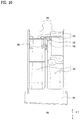
- FIG. 10 shows a top view of the detergent storage unit 300 that constitutes a portion of the detergent supply.
- the detergent storage unit 300 has a handle 305 at a front end thereof.
- the opening protection wall 210 extends so that the rear end thereof is located in rear of the opening extension portion 130 so as to surround and support the handle 305.
- the handle 305 disposed at the front end of the detergent storage unit 300 may be located on the protective casing 200 and the detergent opening 120 when the detergent storage unit 300 is housed inside the cabinet 100, so that a front face of the handle 305 is exposed to the outside of the cabinet 100.
- a gripping groove that may be held by the user may be formed in a front face of the handle 305. Accordingly, the user may extend or retract the detergent storage unit 300 from or into the cabinet 100 while holding the handle 305 of the detergent storage unit 300.
- the handle 305 may be disposed at the front end of the detergent storage unit 300.
- the handle 305 may be located inside the protective casing 200 extending in the front and rear direction X and having the rear end located in rear of the opening extension portion 130.
- the handle 305 may be surrounded with the opening protection wall 210 of the protective casing 200 and supported by the opening protection wall 210.
- a front view of a cross-sectional shape of the handle 305 may correspond to that of a cross-sectional shape of the opening protection wall 210.
- FIG. 7 shows a rear wall 270 of the protective casing 200 according to one implementation of the present disclosure.
- FIG. 9 shows a cross section of the rear wall 270.
- the protective casing 200 may further include the rear wall 270.
- the rear wall 270 may be located in rear of the opening extension portion 130 and may be connected to the opening protection wall 210, and may have a through-opening 272 defined therein which the detergent storage unit 300 passes through.
- a portion of the detergent storage unit 300 retracting inside the cabinet 100 may be located in rear of the rear wall 270, and a rest thereof may be supported forwards by the rear wall 270, such that a retracting distance thereof may be limited.
- the rear wall 270 may extend in a parallel manner to the front panel 110 of the cabinet 100.
- the rear wall 270 may extend along a boundary between an interior of the protective casing 200 surrounded with the opening protection wall 210 and an interior of the cabinet 100.
- the protective casing 200 may be constructed such that the rear end of the opening protection wall 210 is located in rear of the opening extension portion 130.
- the rear wall 270 may be connected to the rear end of the opening protection wall 210. That is, the rear wall 270 may constitute a rear face of the protective casing 200.
- the through-opening 272 may be defined in the rear wall 270. the detergent storage unit 300 passes through the through-opening 272.
- the through-opening 272 may be constructed to have a cross-sectional shape corresponding to that of the detergent storage unit 300, such that the detergent storage unit 300 may stably retract into the cabinet 100 through the through-opening 272.
- the handle 305 of the detergent storage unit 300 may be accommodated inside the protective casing 200. A rest portion of the detergent storage unit 300 except the handle 305 may retract into the cabinet 100 through the through-opening 272.
- the detergent storage unit 300 may have a detergent receiving space 320 in which detergent is stored and received.
- the space 320 may be formed in rear of the handle 305.
- the storage 300 may include a detergent storage unit container in which detergent is stored and/or a detergent cup having an open top face and storing therein detergent.
- the storage 300 may include a storage frame in which the detergent receiving space 320, the detergent storage unit container and/or detergent cup are arranged are disposed.
- FIG. 10 shows the detergent storage unit 300 according to one implementation of the present disclosure.
- the storage 300 includes the storage frame that is coupled with the handle 305 and is disposed in rear of the handle 305.
- the storage frame has the detergent receiving space 320 defined therein in which detergent is stored.
- the detergent cup or the detergent storage unit container may be inserted into inner spaces of the storage frame.
- the handle 305 may have a front cross-sectional area different from that of the storage frame in rear of the handle 305.
- the handle 305 may be constructed to have a larger front cross-sectional area than that of the storage frame in rear of the handle 305.
- a portion of the detergent storage unit 300 such as the handle 305 may be located inside the protective casing 200, while a rest portion thereof such as the storage frame, etc. may be accommodated inside the cabinet 100.
- a portion of the detergent storage unit 300 retracts into the cabinet 100 and a rest portion thereof is located inside the protective casing 200.
- a retracting distance of this detergent storage unit 300 may be limited by the rear wall 270.
- the rear wall 270 may restrict rearward movement of a protruding portion of the detergent storage unit 300. Accordingly, the portion of the detergent storage unit 300 comes into contact with the rear wall 270 and is supported forwards by the rear wall, such that the rearward movement thereof is prohibited.
- the portion of the detergent storage unit 300 may be supported by the rear wall 270 and may be disposed inside the protective casing 200.
- the retracting distance thereof to the inside of the cabinet 100 may be limited by the rear wall 270.
- the handle 305 of the detergent storage unit 300 may be supported forwards by the rear wall 270, while a rest portion thereof may retract into the cabinet 100 through the through-opening 272.
- the handle 305 has a larger cross-sectional area than that of the storage frame in rear of the handle.
- the handle 305 may be supported forwards by the rear wall 270.
- a portion of the detergent storage unit 300 that is, the storage frame thereof passes through the through-opening 272 and has retracted into the cabinet 100, and a rest portion thereof, that is, the handle 305 is supported forwards by rear wall 270, such that the retracting distance of the storage 300 into the cabinet 100 is limited.
- the handle 305 may be stably supported by the rear wall 270, thereby improving structural stability, and effectively fixing the detergent storage unit 300.
- the detergent supply for supplying the detergent to the drum 14 may be disposed inside the cabinet 100.
- the detergent storage unit 300 retracting into the cabinet 100 may define a portion of the detergent supply.
- the detergent supply may further include the supply casing 400 and the dispenser 450.
- the laundry treating apparatus 10 may further include the supply casing 400.
- the supply casing 400 may be disposed inside the cabinet 100, and the front end of the casing 400 may be coupled to the protective casing 200.
- the casing 400 may accommodate therein the detergent storage unit 300 that has retracted into the cabinet 100.
- the supply casing 400 may be located in rear of the protective casing 200, and may accommodate therein the detergent storage unit 300 that has retracted into the cabinet 100. A front end of the supply casing 400 facing towards the protective casing 200 may be coupled to the protective casing 200.
- the front panel 110, the protective casing 200 and the supply casing 400 may have coupling relationships therebetween.
- a stable structure may be realized, and the detergent storage unit 300 retracting into the cabinet 100 may be effectively accommodated in the supply casing 400.
- the front end of the supply casing 400 may be coupled to the rear wall 270 of the protective casing 200.
- the rear wall 270 of the protective casing 200 may be constructed to extend along a boundary between the interior of the protective casing 200 and the interior of the cabinet 100.
- the front end of the supply casing 400 may face toward the rear wall 270.
- the front end of the supply casing 400 may be coupled to the rear wall 270 of the protective casing 200.
- a coupling scheme between the supply casing 400 and the rear wall 270 may vary.
- a through-member such as a screw or a rivet may pass through both of the rear wall 270 and the supply casing 400.
- a fitting-type fastener such as a hook may be disposed on the rear wall 270 or the supply casing 400.
- FIG. 7 shows that a through coupler is disposed on each of both sides of the rear wall 270 in the lateral direction Y and the through member passes through the through coupler, according to one implementation of the present disclosure.
- the through member passing through the through coupler may be coupled to the supply casing 400.
- the laundry treating apparatus 10 may further include the dispenser 450.
- the dispenser 450 may be disposed inside the cabinet 100 and may supply washing-water to the detergent storage unit 300 that has retracted into the cabinet 100.
- the dispenser 450 may be placed above the supply casing 400.
- the dispenser 450 may define a portion of the detergent supply, and may be disposed inside the cabinet 100 and may be constructed to supply the washing-water to the detergent storage unit 300.
- the detergent storage unit 300 retracting into the cabinet 100 is accommodated in the supply casing 400.
- the dispenser 450 supplies washing-water to the detergent storage unit 300.
- the detergent stored inside the detergent storage unit 300 is discharged into the supply casing 400 together with the washing-water.
- the supply casing 400 may deliver the washing-water and the detergent discharged from the detergent storage unit 300 to the drum 14 inside cabinet 100.
- the dispenser 450 may be placed above the supply casing 400, and may be coupled to supply casing 400.
- the dispenser 450 may be manufactured separately from the supply casing 400 or the top face of the supply casing 400 may define the dispenser 450.
- the dispenser 450 may be placed above the supply casing 400 and may have organic coupling relationships with the supply casing 400, the detergent storage unit 300 and the protective casing 200. That is, the detergent storage unit 300 retracted through the protective casing 200 may be accommodated inside the supply casing 400 that is coupled to the protective casing 200 and is disposed in rear of the protective casing 200. Washing-water from the dispenser 450 supported upwards by the supply casing 400 may be supplied to the detergent storage unit 300.
- the detergent storage unit 300 has the detergent receiving space 320 defined therein in which detergent is accommodated.
- a detergent outlet 330 may be defined in a rear face of the storage 300 and communicate with the detergent receiving space 320.
- the detergent may be discharged through the detergent outlet 130 into the drum.
- a rear end of the bottom face 340 of the detergent storage unit 300 is located in rear of the rear face thereof to prevent detergent leakage.
- the detergent storage unit 300 may have the detergent receiving space 320 defined in the storage frame that has retracted into the cabinet 100.
- the detergent outlet 330 may be defined in the rear face of the detergent storage unit 300 to discharge the detergent contained in the detergent receiving space 320 into the drum.
- the detergent stored in the detergent receiving space 320 may be discharged to the outside of the detergent storage unit 300 through the detergent outlet 330 which is defined in the rear face of the detergent storage unit 300 and communicates with the detergent receiving space 320.
- the bottom face 340 of the detergent storage unit 300 may extend so that the rear end of the bottom face 340 is located in rear of the rear face. That is, the detergent discharged through the detergent outlet 330 defined in the rear face of the detergent storage unit 300 flows on the rear end of the bottom face 340 and may be discharged to the outside of the detergent storage unit 300.
- a portion of the detergent stored in the detergent receiving space 320 of the detergent storage unit 300 may be unintentionally discharged through the detergent outlet 330, or the detergent remaining in a flow path of the detergent may be discharged through the detergent outlet 330 during the transfer of the detergent storage unit 300.
- the detergent or the washing-water may leak from the detergent outlet to the opening protection wall 210 of the protective casing 200.
- the detergent and the washing-water leaking from the detergent storage unit 300 may act adversely, for example, may induce corrosion of the opening extension portion 130 or deform the opening protection wall 210.
- the bottom face 340 of the detergent storage unit 300 extends such that the rear end thereof is located in rear of the rear face of the storage 300 in which the detergent outlet 330 is formed.
- the protective casing 200 may include an opening stopper 275.
- the detergent storage unit 300 may include a stopper protrusion 370.
- FIG. 7 shows the opening stopper 275 disposed on the protective casing 200.
- FIG. 9 schematically shows a positional relationship between the opening stopper 275 and the stopper protrusion 370.
- FIG. 10 shows a top view of the stopper protrusion 370 of the detergent storage unit 300.
- the opening stopper 275 may be disposed on the protective casing 200 and be constructed to protrude toward the detergent storage unit 300. Further, the stopper protrusion 370 of the detergent storage unit 300 may be constructed to overlap at least a portion of the opening stopper 275 in the front and rear direction X.
- the stopper protrusion 370 may be constructed to come into contact with the opening stopper 275 when the storage 300 is moving in the front and rear direction X. While the detergent storage unit 300 has retracted into the cabinet 100, the stopper protrusion 370 may be spaced rearwardly away from the opening stopper 275.
- a shape or a location of the opening stopper 275 may vary.
- the opening stopper 275 may protrude from the inner face of the opening protection wall 210 or may protrude from an inner face of the through-opening 272 defined in the rear wall 270 as described later.
- stopper protrusion 370 may vary.
- the stopper protrusion 370 may be disposed on the storage frame of detergent storage unit 300, and may protrude upward from detergent storage unit 300 as described below.
- FIG. 11 shows a state in which the detergent storage unit 300 retracted into the cabinet 100 extends by a predefined extending distance to be described later, and the stopper protrusion 370 and the opening stopper are in contact with each other, according to one implementation of the present disclosure.
- the stopper protrusion 370 may contact the opening stopper 275 such that an extending distance of the storage 300 may be limited.
- the detergent storage unit 300 may eventually be received and utilized in the supply casing 400. Accordingly, the detergent storage unit 300 may extend outside the cabinet 100 by a predetermined extending distance and may be used by the user.
- the predefined extending distance of the detergent storage unit 300 may be determined by adjusting a spacing between the stopper protrusion 370 of the detergent storage unit 300 retracting into the cabinet 100 and the opening stopper 275 of the protective casing 200.
- the term "the predefined extending distance" refers to an extending distance by which the detergent storage unit 300 retracting into the cabinet 100 may extend by a design. Referring to FIG. 9 , the predefined extending distance may correspond to the spacing between the stopper protrusion 370 and the opening stopper 275 or an inner stopper 460 which will be described later. While the detergent storage unit 300 has extended by the predefined extending distance, the detergent receiving space 320 may be exposed to the outside, so that a process in which the user stores the detergent in the detergent storage unit 300 is not inconvenient.
- the protective casing 200 has the opening stopper 275 that contacts the stopper protrusion 370 of the detergent storage unit 300 and thus restricts the forward movement of the stopper protrusion 370.
- a sufficient spacing between the stopper protrusion 370 and the opening stopper 275 may be secured.
- the sufficient predefined extending distance of the detergent storage unit 300 may be secured so that the detergent receiving space 320 may be exposed to the outside.
- the opening stopper 275 may protrude from an inner circumferential face surrounding the through-opening 272 of the rear wall 270 toward the through-opening 272.
- the opening stopper 275 may be disposed on the rear wall 270, and may protrude from the inner face or the inner circumferential face surrounding the through-opening 272 of the rear wall 270 toward the through-opening 272.
- the opening stopper 275 may be constructed to screen a portion of the through-opening 272 in the front and rear direction X.
- a specific protrusion direction or shape of the opening stopper 275 may be variously determined as needed in relation to the stopper protrusion 370, and the like.
- FIG. 11 shows a state in which the opening stopper 275 protruding from the rear wall 270 of the protective casing 200 and the stopper protrusion 370 of the detergent storage unit 300 contact each other, according to one implementation of the present disclosure.
- the opening stopper 275 may protrude from the rear wall 270 in which the through-opening 272 is formed. This may be advantageous for the opening stopper 275 to be positioned to contact the stopper protrusion 370 during the entering or drawn-out process of the detergent storage unit 300.
- the opening stopper 275 may be constructed to extend or protrude downward from the protective casing 200.
- the stopper protrusion 370 may be constructed to extend or protrude upward from the detergent storage unit 300.
- the opening stopper 275 disposed on the rear wall 270 of the protective casing 200 may be located above the through-opening 272.
- the stopper protrusion 370 may protrude upward from the top face of the detergent storage unit 300.
- the stopper protrusion 370 may be disposed on the storage frame located in rear of the handle 305 of the detergent storage unit 300.
- the opening stopper 275 is positioned above the detergent storage unit 300, and the stopper protrusion 370 protrudes upwards from a top of the storage 300.
- the predefined extending distance may be defined by the opening stopper 275 and the stopper protrusion 370 while unnecessary structural interference along the movement of the detergent storage unit 300 is minimized.
- the stopper protrusion 370 may be located at the center of detergent storage unit 300 in the lateral direction Y.
- the opening stopper 275 may be located at a center of a top of the through-opening 272 defined therein the rear wall 270 in a positional corresponding manner with the stopper protrusion 370.
- a position of one end of the detergent storage unit 300 is fixed while the other end thereof has the stopper protrusion 370.
- the other end further has a stopper bar 380 whose a position is variable along a protruding direction of the stopper protrusion 370.
- the detergent storage unit 300 may further include the stopper bar 380.
- a position of one end of the stopper bar 380 is fixed, and the other end thereof has the stopper protrusion 370.
- a position of the other end thereof may vary along the protruding direction of the stopper protrusion 370.
- one end of the stopper bar 380 may be fixed to the detergent storage unit 300.
- the stopper bar 380 may be manufactured separately from the detergent storage unit 300 and nay be coupled to the detergent storage unit 300, or may be integrally formed with the detergent storage unit 300, for example, the storage frame.
- one end of the stopper bar 380 may be fixed to the detergent storage unit 300, and the other end thereof may define a free end whose a position is variable around one end. That is, one end of the stopper bar 380 may define a fixed end fixed to the detergent storage unit 300, and the other end thereof may define a free end separated from the detergent storage unit 300.
- the stopper bar 380 may have the stopper protrusion 370 at the other end of the stopper bar 380. That is, the stopper protrusion 370 may be disposed on the other end thereof and a position thereof may vary together with the other end thereof. The change in the position of the other end thereof may be achieved via deformation of the stopper bar 380 resulting from pressing one end.
- stopper protrusion 370 may protrude upward from the other end of stopper bar 380.
- the other end of the stopper bar 380 may move approximately along the vertical Z direction when one end thereof is pressed. That is, the other end of the stopper bar 380 defining the free end may vary in position along a direction parallel to the protruding direction of the stopper.
- the stopper protrusion 370 may move downward together with the other end of the stopper bar 380.
- the detergent storage unit 300 may extend out of the cabinet 100 through the detergent opening 120 while the extending distance is not limited by the opening stopper 275.
- the user may selectively press one end of the stopper bar 380 disposed on the detergent storage unit 300 as needed and thus selectively and completely extend the detergent storage unit 300 from the cabinet 100.
- a direction of extension of the stopper bar 380 may be varied as required.
- the stopper bar 380 may be disposed on a side face of the detergent storage unit 300 and extend in the vertical direction Z or the front and rear direction X, or may be disposed on the top face of the detergent storage unit 300 and extend in the front and rear direction X or the lateral direction Y.
- the stopper bar 380 extends along the front and rear direction X of the detergent storage unit 300. The front end thereof is fixed to the detergent storage unit 300.
- the stopper protrusion 370 is disposed on the rear end thereof. While the stopper protrusion 370 is in contact with the opening stopper 275, the front end thereof may be exposed to the outside of the cabinet 100.
- the change in the position of the other end of the stopper bar 380 may be caused by pressing one end thereof.
- One end thereof may be selectively pressed by the user.
- the stopper bar 380 extends along the front and rear direction X from the top face of the detergent storage unit 300 so that one end of the stopper bar 380 is easily pressed by the user.
- One end thereof may define a front end.
- the stopper bar 380 extends in the front and rear direction X, and the front end thereof is fixed to the detergent storage unit 300.
- the stopper protrusion 370 is disposed on the rear end thereof.
- the front end thereof may be exposed to the outside of the cabinet 100 such that the user may easily press the front end.
- the front end of the stopper bar 380 may be fixed to the detergent storage unit 300, and the front end of the stopper bar may be exposed to the outside of the cabinet 100 while the stopper protrusion 370 is in contact with the opening stopper 275.
- FIG. 11 shows a state in which the front end of the stopper bar 380 is exposed to the outside of the cabinet 100 while the forward movement of the stopper protrusion 370 is restricted by the opening stopper 275, according to one implementation of the present disclosure.
- the front end of the stopper bar 380 may be exposed to the outside even when the storage 300 is located inside the protective casing 200 as shown in FIG. 11 .
- a cross-sectional area of the protective casing 200 may correspond to that of the handle 305 of the detergent storage unit 300.
- the storage frame disposed in rear of the handle 305 may have a smaller cross-sectional area than that of the handle 305.
- the front end of the stopper bar 380 disposed on the top face of the storage frame may be exposed to the outside even when the storage 300 is received in the protective casing 200.
- FIGS. 9 and 11 show the inner stopper 460 located inside the cabinet 100.
- FIG. 12 shows a rear view of the inner stopper 460.
- one implementation of the present disclosure may further include an inner stopper 460.
- the inner stopper 460 may be disposed inside the cabinet 100, and may protrude toward the detergent storage unit 300 that has retracted into the cabinet 100.
- the inner stopper 460 may be constructed to overlap the stopper protrusion 370 of the detergent storage unit 300 along the front and rear direction X, as in the opening stopper 275. That is, the stopper protrusion 370 may be in contact with the inner stopper 460 and/or the opening stopper 275 during the drawn-out process of the detergent storage unit 300, so that the extension of the detergent storage unit 300 may be limited.
- the inner stopper 460, the opening stopper 275 and the stopper protrusion 370 may be arranged in the front and rear direction X. That is, the opening stopper 275, the inner stopper 460, and the stopper protrusion 370 may be arranged approximately in a line along the front and rear direction X.
- the inner stopper 460 may limit the extending distance of the detergent storage unit 300 while contacting the stopper protrusion 370. Accordingly, in the laundry treating apparatus 10 according to one implementation of the present disclosure, the extending distance of the detergent storage unit 300 may be adjusted in a stepwise manner.
- the inner stopper 460 may be located in rear of the opening stopper 275, and may be located in front of the stopper protrusion 370 of the detergent storage unit 300 that has retracted into the cabinet 100.
- the stopper protrusion 370 sequentially contacts the inner stopper 460 and the opening stopper 275, the stopper protrusion 370 first contacts the inner stopper 460 such that the extending distance of the detergent storage unit 300 may be first limited. Then, the stopper protrusion 370 passes by the inner stopper 460 when the user pressurizes the front end of the stopper bar 380. Thus, the stopper protrusion 370 contacts the opening stopper 275 such that the extending distance of the detergent storage unit 300 may be second limited.
- a distance L1 between the inner stopper 460 and the stopper protrusion 370 of the detergent storage unit 300 completely retracting into the cabinet 100 may correspond to a first predefined extending distance.
- a distance L2 between the stopper protrusion 370 and the opening stopper 275 may correspond to a second predefined extending distance.
- the first predefined extending distance may be set to be larger than the second predefined extending distance.
- the L1 and L2 may be determined by controlling the positions of the opening stopper 275, the inner stopper 460 and the stopper protrusion 370.
- the opening stopper 275 and the inner stopper 460 may be spaced apart from each other, and may be located in front of the stopper protrusion 370, and may protrude downwards.
- the stopper protrusion 370 may protrude upward and may be disposed in rear of the opening stopper 275 and the inner stopper 460 and overlap with the opening stopper 275 and the inner stopper 460 in the front and rear direction X.
- the stopper protrusion 370 bypasses the inner stopper 460 during the drawn-out process of the detergent storage unit 300 and contacts opening stopper 275.
- the stopper protrusion 370 contacts the inner stopper 460, and then bypasses the opening stopper 27, Alternatively, the stopper protrusion 370 may contact sequentially the inner stopper 460 and the opening stopper 275.
- a correlation between the opening stopper 275, the inner stopper 460 and the stopper protrusion 370 may be described as follows.
- the inner stopper 460 may be disposed inside the cabinet 100, and may protrude toward the detergent storage unit 300.
- the opening stopper 275 may be located in front of the inner stopper 460 and may protrude toward the detergent storage unit 300.
- the stopper protrusion 370 may be disposed on the detergent storage unit 300.
- the stopper protrusion 370 may be located in rear of the inner stopper 460 while the detergent storage unit 300 has retracted into the cabinet 100. During the drawn-out process of the detergent storage unit 300, the stopper protrusion 370 may contact at least one of the inner stopper 460 and the opening stopper 275 to limit the extending distance of the detergent storage unit 300.
- the protective casing 200 is coupled to the inner face of the front panel 110.
- the detergent storage unit 300 passes through the protective casing 200.
- the protective casing 200 includes the opening stopper 275.
- the dispenser 450 may be located in rear of the protective casing 200.
- the dispenser 450 may supply washing-water to the detergent storage unit 300.
- the dispenser 450 may include the inner stopper 460.
- FIG. 12 shows a rear view of the stopper protrusion 370 having a bypass region 375 defined therein to bypass the inner stopper 460 in the lateral direction Y.
- FIG. 13 shows a rear view of the stopper protrusion 370 which is constructed to overlap at least partially the inner stopper 460, and the opening stopper 275 in the front and rear direction X.
- the stopper protrusion 370 is constructed to overlap with the opening stopper 275 but not to overlap with the inner stopper 460 along the front and rear direction X. Thus, in the drawn-out process of the detergent storage unit 300, the stopper protrusion 370 may bypass the inner stopper 460 and may come into contact with the opening stopper 275.
- the stopper protrusion 370 may be constructed not to contact the inner stopper 460, and may be constructed to contact the opening stopper 275 in the front and rear direction X.
- the bypass region 375 may be embodied as an empty space.
- the bypass region 375 may be located in rear of the inner stopper 460, and may be located on a side of the stopper protrusion 370.
- the bypass region 375 may have a cross-sectional area greater than that of the inner stopper 460 in a front view.
- the inner stopper 460 may bypass the stopper protrusion 370 through the bypass region 375. Accordingly, the movement of the stopper protrusion 370 may not be restricted by the inner stopper 460 during the drawn-out process of the detergent storage unit 300.
- the stopper protrusion 370 bypasses the inner stopper 460 and comes into contact with the opening stopper 275 such that movement thereof is limited. Therefore, the detergent storage unit 300 may extend from the cabinet by a predefined extending distance set by the position of the opening stopper 275.
- a length of the detergent storage unit 300 or the location of the stopper protrusion 370 may be determined in various ways by design, and may vary according to a type of the detergent storage unit 300.
- the bypass region 375 may be defined on a side of the stopper protrusion 370 of the detergent storage unit 300.
- the bypass region 375 may be located in rear of the inner stopper 460.
- the inner stopper 460 may pass through the bypass region 375 and may bypass the stopper protrusion 370 in the drawn-out process of the detergent storage unit 300.
- the bypass region 375 formed on the side of the stopper protrusion 370 may be located in rear of the opening stopper 275, and the stopper protrusion 370 may be constructed to overlap with the inner stopper 460 in the front and rear direction X.
- the stopper protrusion 370 comes into contact with the inner stopper 460 and thus movement thereof is restricted.
- the opening stopper 275 passes through the bypass region 375 and bypasses the stopper protrusion 370, and the stopper protrusion 370 may bypass the opening stopper 275.
- the stopper protrusion 370 free of the bypass region 375 may be constructed to overlap the opening stopper 275 and the inner stopper 460 in the front and rear direction X.
- the laundry treating apparatus 10 has both of the opening stopper 275 and the inner stopper 460.
- the opening stopper 275 and the inner stopper 460 may be selectively used, and the extending distance of the detergent storage unit 300 may be effectively limited.
- FIG. 12 shows the detergent storage unit 300 in which the bypass region 375 overlapping with the inner stopper 460 in the front and rear direction X is located on a side of the stopper protrusion 370 in the lateral direction Y according to one implementation of the present disclosure.
- one side 276 of the opening stopper 275 in the lateral direction Y overlaps the inner stopper 460 in the front and rear direction X, and the other side 278 thereof does not overlap the inner stopper 460.
- the stopper protrusion 370 may be constructed to overlap the other side 278 of the opening stopper 275 in the front and rear direction X.
- the opening stopper 275 may be constructed so that one side 276 thereof faces the inner stopper 460, while the other side 278 thereof does not face the inner stopper 460. That is, the inner stopper 460 may be constructed to overlap only with one side 276 of the opening stopper 275.
- the stopper protrusion 370 may be constructed not to overlap with the inner stopper 460, and may be constructed to overlap with the other side 278 of the opening stopper 275. That is, the stopper protrusion 370 may be constructed to be spaced from the inner stopper 460 in the lateral direction Y and overlap with a portion of the opening stopper 275 in the rear view as shown in FIG. 12 .
- the stopper protrusion 370 may bypass the inner stopper 460 and contact the opening stopper 275 such that movement thereof is limited.
- the detergent storage unit 300 has the bypass region 375 open along the front and rear direction X of the detergent storage unit 300 on the side of the stopper protrusion 370.
- the inner stopper 460 is constructed to face the bypass region 375 along the front and rear direction X. In the drawn-out process of the detergent storage unit 300, the inner stopper 460 may pass through the bypass region 375, and the stopper protrusion 370 may be in contact with the opening stopper 275 such that the extending distance thereof may be limited.
- the detergent storage unit 300 may be constructed such that the stopper protrusion 370 overlaps the inner stopper 460, as shown in FIG. 13 .
- one side 276 of the opening stopper 275 may overlap the inner stopper 460 in the front and rear direction X.
- the stopper protrusion 370 is constructed to overlap with one side 276 of the opening stopper 275 and the inner stopper 460 in the front and rear direction X.
- the detergent storage unit 300 may not have the bypass region 375 on the side of the stopper protrusion 370 as shown in FIG. 13 .
- the inner stopper 460 overlaps one side 276 of the opening stopper 275 in the front and rear direction X.
- the stopper protrusion 370 overlapping the inner stopper 460 in the front and rear direction X may be brought into contact with the opening stopper 275 during the drawn-out process of the detergent storage unit 300.
- the opening stopper 275 is constructed such that at least a portion thereof overlaps the inner stopper 460 along the front and rear direction X.
- the stopper protrusion 370 contacts the inner stopper 460 and the opening stopper 275 in a sequential manner during the drawn-out process of the detergent storage unit 300, thereby limiting the extending distance of the detergent storage unit 300 in a stepwise manner.
- the detergent storage unit 300 may extend from the cabinet 100 by the first predefined extending distance when the stopper protrusion 370 contacts inner stopper 460.
- the stopper protrusion 370 bypasses the inner stopper 460 using the stopper bar 380, the stopper protrusion 370 comes into contact with the opening stopper 275 again, such that the three storages may extend from the cabinet 100 by the second predefined extending distance.
- the stopper bar 380 may be constructed such that the front end thereof is exposed to the outside of the cabinet 100 while the stopper protrusion 370 is in contact with the inner stopper 460.
- one side 276 of the opening stopper 275 is positioned side by side with the inner stopper 460 in the front and rear direction X, while the other side 278 thereof is constructed not to overlap with the inner stopper 460.
- This is advantageous because the use of the inner stopper 460 and the opening stopper 275 may be efficiently selected based on the position of the stopper protrusion 370 according to the replacement or design of the detergent storage unit 300.
Landscapes
- Engineering & Computer Science (AREA)
- Textile Engineering (AREA)
- Detail Structures Of Washing Machines And Dryers (AREA)
Abstract
Description
- The present disclosure relates to a laundry treating apparatus, and more specifically, relates to a laundry treating apparatus having a detergent supply.
- The laundry treating apparatus receives laundry including clothes, bedding, etc. inside a drum and removes contaminations from the laundry. The laundry treating apparatus may perform processes such as washing, rinsing, spinning and drying. The laundry treating apparatus may be classified into a top loading scheme apparatus and a front loading front scheme apparatus based on a scheme in which laundry is injected into the drum.
- The laundry treating apparatus may include a cabinet defining an appearance, a tub accommodated inside the cabinet, a drum that is rotatably mounted inside the tub, and into which laundry is injected, and a detergent supply that supplies detergent into the drum.
- When the drum rotates by a motor while washing-water is supplied to the laundry contained in the drum, dirt on the laundry may be removed via friction between, the laundry, the drum and the washing-water.
- The detergent supply has a detergent supply function to improve the washing effect. In this connection, detergent refers to substances that enhance the washing effect, such as fabric detergent, fabric softener and fabric bleach. Detergent may be used in a powder form and a liquid form. In one example, Korean Patent Application Publication No.
10-2018-0090003 A1 - The detergent storage unit may enter or drawn out through a detergent opening of the cabinet. In this process, when the detergent accidentally leaks from the detergent storage unit into a portion of the cabinet around the detergent opening, corrosion of the portion of the cabinet may occur, resulting in reduced durability. Damage such as scratches may occur on a surface of the detergent storage unit due to edges of the cabinet around the detergent opening.
- Therefore, it is an important challenge to effectively prevent the deterioration of the durability of the cabinet, or the damage to the detergent storage unit, as caused when the detergent storage unit retracts or extends into or from the cabinet.
- Implementations of the present disclosure are intended to provide a laundry treating apparatus that may effectively suppress corrosion or deformation of the cabinet and improve durability thereof.
- Further, implementations of the present disclosure are intended to provide a laundry treating apparatus that has excellent structural stability, improved coupling stability, and efficient arrangement between components.
- Further, implementations of the present disclosure are intended to provide a laundry treating apparatus that may effectively improve utility of the detergent storage unit.
- Purposes of the present disclosure are not limited to the above-mentioned purpose. Other purposes and advantages of the present disclosure as not mentioned above may be understood from following descriptions and more clearly understood from embodiments of the present disclosure. Further, it will be readily appreciated that the purposes and advantages of the present disclosure may be realized by features and combinations thereof as disclosed in the claims.
- The laundry treating apparatus according to one implementation of the present disclosure may include a protective casing to prevent corrosion or durability degradation otherwise caused when detergent or washing water is discharged onto a portion of the cabinet around the detergent opening defined in a front panel when a drawer type detergent storage unit extends or retracts from or into the cabinet through the detergent opening.
- A coating on an exposed portion of the front panel around the detergent opening may be peeled off due to corrosion resulting from leakage of the detergent from the detergent storage unit. Thus, in one implementation of the present disclosure, a coupling structure wrapping the exposed portion of the front panel using an injection molded component may prevent detergent from contacting the portion of the front panel.
- The cabinet may include a stainless steel (STS) material. The detergent opening may be defined in the cabinet by partially opening the cabinet. Thus, an inner face of the opening may be exposed to an outside and thus may be vulnerable to the corrosion.
- In one implementation of the present disclosure, the protective casing coupled to an opening extension portion of the front panel may be a plastic injection-molded component. The protective casing may have a structure that covers the exposed inner face of the opening defined in the cabinet. The protective casing may be coupled to a rear face of the front panel of the cabinet in a hooked manner.
- One aspect of the present disclosure provides a laundry treating apparatus comprising: a cabinet including a front panel having a detergent opening defined therein; a tub disposed inside the cabinet; a drum rotatably disposed inside the tub; and a detergent storage unit retracting into the cabinet through the detergent opening, wherein detergent to be supplied to the drum is stored in the detergent storage unit, wherein the front panel has an opening extension portion extending from a periphery of the detergent opening toward an inside of the cabinet, wherein the apparatus further comprises a protective casing disposed inside the cabinet and coupled to the opening extension portion, wherein the protective casing surrounds at least a portion of the detergent storage unit retracting into the cabinet through the detergent opening, wherein the protective casing includes an opening protection wall constructed to cover an inner face of the opening extension portion facing toward the detergent opening to protect the opening extension portion.
- In one implementation, the opening protection wall surrounds the detergent opening, and is located between the opening extension portion and the detergent storage unit to screen at least a portion of the inner face of the opening extension portion.
- In one implementation, the protective casing further includes an opening coupler disposed on an outer face of the opening protection wall facing toward the opening extension portion, wherein the opening extension portion is inserted into and coupled to the opening coupler in a front to rear direction.
- In one implementation, the opening coupler includes: an outward extension portion extending outwards from the outer face of the opening protection wall; and a frontward extension portion extending forwards from the outward extension portion and spaced apart from the opening protection wall, wherein the opening extension portion is inserted into a space between the opening protection wall and the frontward extension portion.
- In one implementation, a front end of the opening protection wall is located in front of a front end of the frontward extension portion.
- In one implementation, the opening protection wall extends so that a rear end thereof is located in rear of the opening extension portion and supports at least a portion of the detergent storage unit retracting into the cabinet.
- In one implementation, the opening protection wall includes an opening coupling protrusion protruding outwards from the outer face, wherein the opening extension portion includes a protrusion receiving portion into which the opening coupling protrusion is inserted.
- In one implementation, the opening coupling protrusion is located in front of a front end of the frontward extension portion.
- In one implementation, the opening extension portion includes: a first extension portion extending rearward from the front panel by a first length; and a second extension portion extending rearward from the front panel by a second length larger than the first length, wherein the protrusion receiving portion is defined in the second extension portion.
- In one implementation, the opening coupler includes: a first coupler portion into which the first extension portion is inserted; and a second coupler portion disposed in rear of the first extension portion, wherein the second extension portion is inserted into the second coupler portion.
- In one implementation, the outward extension portion of the second coupler portion has a separation opening defined therein, wherein the separation opening is disposed in rear of the opening coupling protrusion and exposes the second extension portion in a rear direction.
- In one implementation, a height of the outward extension portion of the second coupler portion in which the separation opening is defined is greater than a height of the outward extension portion of the first coupler portion.
- In one implementation, the opening protection wall further includes an assembly guide protrusion protruding outwards from the outer face, wherein the opening extension portion further include an assembly guide groove open in a rear direction, wherein the assembly guide protrusion is inserted into the assembly guide groove in a rear to front direction.
- In one implementation, the assembly guide protrusion extends forward from the outward extension portion, wherein a front end of the assembly guide protrusion protrudes frontwards of the frontward extension portion.
- In one implementation, the detergent storage unit has a handle on a front end thereof, wherein the opening protection wall extends so that a rear end thereof is located in rear of the opening extension portion and surrounds and supports the handle.
- In one implementation, the protective casing further includes a rear wall located in rear of the opening extension portion and connected to the opening protection wall, wherein the rear wall has a through-opening defined therein through which the detergent storage unit passes, wherein the handle of the detergent storage unit is supported forwards by the rear wall, while a rest portion of the detergent storage unit except for the handle retracts into the cabinet through the through-opening.
- In one implementation, a front face of the handle is coplanar with a front face of the front panel while the handle is in contact with the rear wall.
- In one implementation, the apparatus further comprises a supply casing disposed inside the cabinet, and in rear of the protective casing, wherein a front end of the supply casing is coupled to the rear wall of the protective casing, wherein the supply casing accommodates therein the detergent storage unit retracting into the cabinet.
- In one implementation, the rear wall includes an opening stopper protruding from an inner circumferential face of the through-opening toward the detergent storage unit, wherein the detergent storage unit further includes a stopper protrusion overlapping with the opening stopper in a front and rear direction, wherein during a drawn-out process of the detergent storage unit from the cabinet, the stopper protrusion contacts the opening stopper such that an extending distance of the detergent storage unit is limited.
- In one implementation, the apparatus further comprises an inner stopper disposed inside the cabinet, and protruding toward the detergent storage unit retracting into the cabinet, wherein the inner stopper is located in rear of the opening stopper, and is located in front of the stopper protrusion of the detergent storage unit retracting into the cabinet.
- In one implementation, the apparatus further comprises a dispenser disposed inside the cabinet, and located above the detergent storage unit, wherein the dispenser supplies washing-water to the detergent storage unit, and includes the inner stopper.
- In one implementation, the stopper protrusion is constructed to bypass the inner stopper in the front and rear direction and to contact the opening stopper during the drawn-out process of the detergent storage unit.
- In one implementation, the front panel and the opening extension portion are made of metal, and are integral with each other, wherein the opening protection wall is made of plastic.
- One implementation of the present disclosure may improve the utility of the detergent storage unit simply and effectively using the inner stopper and the opening stopper.
- One implementation of the present disclosure may effectively protect the opening extension portion using the protective casing including the opening protection wall made of plastic material and thus may effectively prevent damage to the detergent storage unit.
- The implementations of the present disclosure may provide the laundry treating apparatus that may effectively suppress corrosion or deformation of the cabinet and improve durability.
- Further, the implementations of the present disclosure may provide the laundry treating apparatus having excellent structural stability, improved coupling stability, and efficient arrangement between the components.
- Further, the implementations of the present disclosure may provide the laundry treating apparatus that may effectively improve the utility of the detergent storage unit.
- In addition to the effects as described above, specific effects of the present disclosure will be described together with the detailed description for carrying out the disclosure.
-
-
FIG. 1 is a diagram showing a laundry treating apparatus according to one implementation of the present disclosure. -
FIG. 2 is a diagram showing a stack-type laundry treating apparatus including upper and lower laundry treating apparatuses according to one implementation of the present disclosure. -
FIG. 3 is a perspective view showing a detergent opening and a protective casing disposed in a front panel of a laundry treating apparatus according to one implementation of the present disclosure. -
FIG. 4 is a diagram showing a cross section of the protective casing coupled to an opening extension portion in a laundry treating apparatus according to one implementation of the present disclosure. -
FIG. 5 is a perspective view showing a state in which the protective casing ofFIG. 3 is spaced from the front panel. -
FIG. 6 is a top view of the protective casing in the laundry treating apparatus according to one implementation of the present disclosure. -
FIG. 7 is a front view of the protective casing in the laundry treating apparatus according to one implementation of the present disclosure. -
FIG. 8 is a diagram showing a state in which an assembly guide protrusion of the protective casing is inserted into an assembly guide groove of the opening extension portion in the laundry treating apparatus according to one implementation of the present disclosure. -
FIG. 9 is a side cross-sectional view of an interior of a cabinet into which a detergent storage unit is inserted in the laundry treating apparatus according to one implementation of the present disclosure. -
FIG. 10 is a diagram showing the detergent storage unit retracting into the detergent opening in the laundry treating apparatus according to one implementation of the present disclosure. -
FIG. 11 is a diagram showing a state in which a stopper protrusion of the detergent storage unit contacts an opening stopper in the laundry treating apparatus according to one implementation of the present disclosure. -
FIG. 12 is a rear view showing the stopper protrusion having a bypass region in the laundry treating apparatus according to one implementation of the present disclosure. -
FIG. 13 is a rear view showing the stopper protrusion from which the bypass region is removed in the laundry treating apparatus according to one implementation of the present disclosure. - Hereinafter, a laundry treating apparatus according to an embodiment of the present disclosure will be described in detail.
- Unless otherwise defined, all terms including technical and scientific terms used herein have the same meaning as commonly understood by one of ordinary skill in the art to which this inventive concept belongs. It will be further understood that terms, such as those defined in commonly used dictionaries, should be interpreted as having a meaning that is consistent with their meaning in the context of the relevant art and will not be interpreted in an idealized or overly formal sense unless expressly so defined herein.
- For simplicity and clarity of illustration, elements in the FIGS. are not necessarily drawn to scale. The same reference numbers in different FIGS. denote the same or similar elements, and as such perform similar functionality. Moreover, descriptions and details of well-known steps and elements are omitted for simplicity of the description. Furthermore, in the following detailed description of the present disclosure, numerous specific details are set forth in order to provide a thorough understanding of the present disclosure. However, it will be understood that the present disclosure may be practiced without these specific details. In other instances, well-known methods, procedures, components, and circuits have not been described in detail so as not to unnecessarily obscure aspects of the present disclosure.
- It will be understood that, although the terms "first", "second", "third", and so on may be used herein to describe various elements, components, regions, layers and/or sections, these elements, components, regions, layers and/or sections should not be limited by these terms. These terms are used to distinguish one element, component, region, layer or section from another element, component, region, layer or section. Thus, a first element, component, region, layer or section described below could be termed a second element, component, region, layer or section, without departing from the spirit and scope of the present disclosure.
- In addition, it will also be understood that when a first element or layer is referred to as being present "on" a second element or layer, the first element may be disposed directly on the second element or may be disposed indirectly on the second element with a third element or layer being disposed between the first and second elements or layers. It will be understood that when an element or layer is referred to as being "connected to", or "coupled to" another element or layer, it may be directly on, connected to, or coupled to the other element or layer, or one or more intervening elements or layers may be present. In addition, it will also be understood that when an element or layer is referred to as being "between" two elements or layers, it may be the only element or layer between the two elements or layers, or one or more intervening elements or layers may also be present.
- The terminology used herein is for the purpose of describing particular embodiments only and is not intended to be limiting of the present disclosure. As used herein, the singular forms "a" and "an" are intended to include the plural forms as well, unless the context clearly indicates otherwise. It will be further understood that the terms "comprises", "comprising", "includes", and "including" when used in this specification, specify the presence of the stated features, integers, operations, elements, and/or components, but do not preclude the presence or addition of one or more other features, integers, operations, elements, components, and/or portions thereof.
- As used herein, the term "and/or" includes any and all combinations of one or more of the associated listed items. Expression such as "at least one of" when preceding a list of elements may modify the entire list of elements and may not modify the individual elements of the list.
-
FIG. 1 is a perspective view of alaundry treating apparatus 10 according to one implementation of the present disclosure. Referring toFIG. 1 , thelaundry treating apparatus 10 according to one implementation of the present disclosure may include acabinet 100 including afront panel 110 having adetergent opening 120 defined therein, atub 12 disposed inside thecabinet 100, and adrum 14 rotatably disposed inside thetub 12. - Specifically, the
laundry treating apparatus 10 may include a washing machine in which laundry is inserted into a washing tub to perform washing, rinsing and dehydration of the laundry, or a dryer in which wet laundry is inserted to perform drying thereof. - The
laundry treating apparatus 10 may be classified into a top load scheme apparatus and a front load scheme apparatus. -
FIG. 1 shows thelaundry treating apparatus 10 as the front load scheme apparatus. This is only for convenience of description. The present disclosure may be applied not only to the washing machine as the front load scheme apparatus, but also to the washing machine as the top load scheme apparatus. - As shown in
FIG. 1 , thelaundry treating apparatus 10 includes thecabinet 100 that defines the appearance thereof. Thecabinet 100 may have thefront panel 110. Adetergent opening 120 may be defined in thefront panel 110. Adetergent storage unit 300 which will be described later may retract or extend into or from thecabinet 100 through thedetergent opening 120. - In one example, the
cabinet 100 may have a manipulator having a display that displays information on an operating state while receiving various control commands from the user. The manipulator may be disposed on thefront panel 110 or a separate control panel. - Further, the
cabinet 100 may have a door installed on thefront panel 110. The door is pivotally disposed on thecabinet 100 to control entry and exit of the laundry into and from thedrum 14. - The
cabinet 100 defines the appearance of thelaundry treating apparatus 10. Thecabinet 100 may have an inner space defined therein in which various components constituting thelaundry treating apparatus 10 may be accommodated. Inside thecabinet 100, thedrum 14 may be installed to accommodate therein the laundry input through an laundry inlet. - Specifically, the
cabinet 100 may receive thetub 12 containing washing-water, and thedrum 14 that is rotatably disposed inside thetub 12 to accommodate laundry therein. A balancer to compensate for eccentricity caused by rotation may be installed at one side of thedrum 14. - The manipulator may include various keys for controlling the operation state of the
laundry treating apparatus 10 and the display for displaying the operation state of thelaundry treating apparatus 10. The door may include a transparent member such as a tempered glass so that the interior of thecabinet 100 or thedrum 14 may be visually identified. - In one example, in one implementation of the present disclosure, the
laundry treating apparatus 10, thedetergent opening 120 may be defined in thefront panel 110. Thedetergent storage unit 300 may retract into thecabinet 100 through thedetergent opening 120. Detergent to be supplied to thedrum 14 may be stored inside thedetergent storage unit 300. A detergent supply may be disposed in rear of the opening and in thecabinet 100. Thedetergent storage unit 300 may define a portion of the detergent supply inside thecabinet 100. - A location and a shape of the
detergent opening 120 may vary.FIG. 1 shows an example in which thedetergent opening 120 is opened frontwards in thefront panel 110 of thecabinet 100. Thedetergent opening 120 may be located in a corner area at a front face of thecabinet 100, for example, on one side of a top portion of thefront panel 110. - The detergent supply may be located inside the
cabinet 100 and in rear of thedetergent opening 120. The detergent supply may include thedetergent storage unit 300 that may store detergent therein, adispenser 450 that is located above thedetergent storage unit 300 and supplies water to thedetergent storage unit 300, and asupply casing 400 that accommodates therein thedetergent storage unit 300 retracting into the cabinet. - The detergent supply serves to automatically supply the detergent stored in the
detergent storage unit 300 into thedrum 14 during the washing step. Detergent refers to a substance that may enhance the laundry effect of the laundry, and may include powder based or liquid based fabric detergent and fabric softener. - In one example,
FIG. 2 shows a stack-type laundry treating apparatus including lower and upperlaundry treating apparatuses laundry treating apparatus 10 according to one implementation of the present disclosure may be stacked on the lowerlaundry treating apparatus 20. In this case, thelaundry treating apparatuses front panels 110 of thelaundry treating apparatuses - The control panel may communicate a signal with the upper
laundry treating apparatus 20 and/or the lowerlaundry treating apparatus 10, and may include a display that provides information on each of the laundry treating apparatuses10 and 20 and a manipulator for controlling each of thelaundry treating apparatuses - As shown in
FIG. 2 , when a plurality oflaundry treating apparatus laundry treating apparatuses - In one example,
FIG. 3 shows thefront panel 110 of thecabinet 100 and aprotective casing 200 coupled to thefront panel 110 in thelaundry treating apparatus 10 according to one implementation of the present disclosure. A side cross-section view of theprotective casing 200 is shown inFIG. 3 . InFIG. 5 , theprotective casing 200 inFIG. 3 is spaced from thefront panel 110. - Referring to
FIGS. 3 to 5 , thelaundry treating apparatus 10 according to one implementation of the present disclosure may further include anopening extension portion 130 in thefront panel 110. Theprotective casing 200 has anopening protection wall 210. - Specifically, the
front panel 110 of thecabinet 100 may have theopening extension portion 130 defined therein that surrounds at least a portion of thedetergent opening 120 and extends inwardly of thecabinet 100. - The
protective casing 200 is coupled to theopening extension portion 130 and is disposed inside thecabinet 100. Theprotective casing 200 may be constructed such that thedetergent storage unit 300 passes through theprotective casing 200. - The
protective casing 200 may include the openingprotection wall 210 that has at least a portion covering an inner face of theopening extension portion 130 facing toward thedetergent opening 120 to protect theopening extension portion 130. - The
opening extension portion 130 may extend rearward from thecabinet 100, and may be constructed to surround at least a portion of thedetergent opening 120. Theopening extension portion 130 may have a ring-shaped closed section extending along a perimeter of thedetergent opening 120. - For example, when the
detergent opening 120 has a circular cross section, theopening extension portion 130 may also have a circular ring shape surrounding thedetergent opening 120. When thedetergent opening 120 has a polygonal cross-sectional shape, theopening extension portion 130 may also have a polygonal ring shape corresponding to thedetergent opening 120. - The
opening extension portion 130 may be manufactured separately from thefront panel 110 and then coupled to a rear face of thefront panel 110 or may be integral with thefront panel 110. When theopening extension portion 130 is integral with thefront panel 110, theopening extension portion 130 may have a bent shape extending rearwards from the periphery of thedetergent opening 120 of thefront panel 110. -
FIG. 5 shows theopening extension portion 130 that extends rearwards from the periphery of thedetergent opening 120 and defines a portion of thefront panel 110 according to one implementation of the present disclosure. - In one example, the
protective casing 200 may be coupled to theopening extension portion 130 and may be disposed inside thecabinet 100. Theprotective casing 200 may be disposed on a rear face of thefront panel 110 and coupled to theopening extension portion 130, and may have a ring-shaped cross section corresponding to a shape of theopening extension portion 130. - Therefore, when the
detergent storage unit 300 retracts into thecabinet 100 through thedetergent opening 120, thedetergent storage unit 300 passes through theopening extension portion 130 and theprotective casing 200 and may retract into thecabinet 100. In other words, thedetergent storage unit 300 may be constructed such that when thedetergent storage unit 300 retracts into thecabinet 100, at least a portion thereof passes through a center of theprotective casing 200 and is surrounded by theprotective casing 200. - In
FIG. 5 , according to one implementation of the present disclosure, thedetergent opening 120 has an approximately rectangular cross section. Theopening extension portion 130 may be embodied as a ring having an approximately rectangular cross section corresponding to that of thedetergent opening 120. Theprotective casing 200 has an approximately rectangular ring cross section corresponding to that of theopening extension portion 130. - In one example, the
protective casing 200 may include the openingprotection wall 210. The openingprotection wall 210 may be constructed such that at least a portion of an outer face thereof away from thedetergent opening 120 covers an inner face of theopening extension portion 130 facing toward thedetergent opening 120. - The opening
protection wall 210 may be constructed to cover theopening extension portion 130 while being in direct contact with or spaced apart from an inner face of theopening extension portion 130 to prevent theopening extension portion 130 from being exposed to the outside. - The opening
protection wall 210 may have a ring shape extending in a front and rear direction X of thecabinet 100. For example, the openingprotection wall 210 may have a ring-shaped cross section having a diameter smaller than that of theopening extension portion 130. - The
protective casing 200 is constructed to be coupled to theopening extension portion 130, and to have the openingprotection wall 210 covering the inner face of theopening extension portion 130, thus preventing theopening extension portion 130 from being exposed to the outside and protecting theopening extension portion 130. - Specifically, the
laundry treating apparatus 10 according to one implementation of the present disclosure may be a washing machine in which detergent and washing-water are used. Thedetergent storage unit 300 retracting or extending through thedetergent opening 120 may contain detergent or water therein. - The
opening extension portion 130 surrounding thedetergent opening 120 in which thedetergent storage unit 300 is located may act as a frame that supports thedetergent storage unit 300 or which is coupled to the detergent supply inside thecabinet 100 to secure rigidity to support the detergent supply. - However, the
opening extension portion 130 may be formed as a portion of thecabinet 100 during a forming process of thecabinet 100, and may be made of a metal material as in thecabinet 100. Accordingly, when water or detergent present in thedetergent storage unit 300 comes into contact with theopening extension portion 130, corrosion of theopening extension portion 130 may occur. - Further, an outer face and an inner face of the
opening extension portion 130 may be coated with a polymer, etc. as in thecabinet 100 such that a coating having corrosion resistance is formed thereon. Even when such a coating is formed, the coating may not protect a rear end of theopening extension portion 130 from corrosion due to a thickness and a manufacturing process of thefront panel 110. - Furthermore, the rear end of the
opening extension portion 130 may have an edge toward thedetergent opening 120. This edge may damage the outer surface of thedetergent storage unit 300 during the retracting or drawn-out process of thedetergent storage unit 300. - Accordingly, one implementation of the present disclosure includes the
protective casing 200 coupled to theopening extension portion 130, wherein theprotective casing 200 has the openingprotection wall 210 covering the inner face of theopening extension portion 130. - The opening
protection wall 210 covers the inner face of theopening extension portion 130 so that theopening extension portion 130 or the rear end of theopening extension portion 130 is not exposed. Thus, water or detergent that may be transferred from thedetergent storage unit 300 may be effectively prevented from being in direct contact with theopening extension portion 130, which otherwise causes corrosion. Further, the damage to the outer surface of thedetergent storage unit 300 by theopening extension portion 130 be effectively prevented. - Further, in one implementation of the present disclosure, the opening
protection wall 210 surrounds thedetergent opening 120 and is located between theopening extension portion 130 and thedetergent storage unit 300, and screens at least a portion of the inner face of theopening extension portion 130. - Accordingly, one implementation of the present disclosure may have a structure in which the
opening protection wall 210 and theopening extension portion 130 are sequentially stacked in a direction from a center of thedetergent opening 120 to an outside as shown inFIG. 4 . The openingprotection wall 210 may be constructed to screen an entirety of theopening extension portion 130 as shown inFIG. 3 or to screen at least a rear end of theopening extension portion 130. - In one example, as described above, in one implementation of the present disclosure, the
front panel 110 may be made of a metal material, and theprotective casing 200 may include a plastic material. - Alternatively, in one implementation of the present disclosure, the
opening extension portion 130 may be made of a metal material, and the openingprotection wall 210 of theprotective casing 200 may be made of a plastic material. - The
opening extension portion 130 may be formed integrally with thefront panel 110, and may be made of a metal material to secure the rigidity of the detergent supply or the supporting force of thedetergent storage unit 300. The openingprotection wall 210 may be made of a plastic material that has corrosion resistance so that thewall 210 is not corroded by water or detergent. - Accordingly, even when the
opening extension portion 130 is made of the metal material to secure the rigidity to support thedetergent storage unit 300 or the detergent supply, theprotective casing 200 or theopening protection wall 210 is made of a plastic material that may have corrosion resistance to prevent corrosion of theopening extension portion 130 which otherwise may occur due to water or detergent that may leak from thedetergent storage unit 300. - In one example,
FIGS. 4 and5 show anopening coupler 230 of theprotective casing 200 to which theopening extension portion 130 is coupled. As shown inFIGS. 4 and5 , in one implementation of the present disclosure, theprotective casing 200 may further include theopening coupler 230. - The
opening coupler 230 is disposed on the outer face of the openingprotection wall 210. Theopening extension portion 130 is inserted in a front to rear direction and is coupled to theopening coupler 230. Specifically, theopening coupler 230 may protrude from an outer face of the openingprotection wall 210 facing toward an opposite side of thedetergent opening 120 in a direction away from thedetergent opening 120. - The
opening coupler 230 may have a ring shape extending in the circumferential direction of thedetergent opening 120 along the circumference of the openingprotection wall 210 and surrounding thedetergent opening 120. The rear end of theopening extension portion 130 may be inserted into theopening coupler 230 in a front to rear direction. The openingprotection wall 210 may move in a rear to front direction of thefront panel 110 and may be inserted into theopening extension portion 130. - The
opening coupler 230 extending outwards from the outer face of the openingprotection wall 210 and extending in the circumferential direction of thedetergent opening 120 may be coupled to theopening extension portion 130, such that theprotective casing 200 may be fixed to a rear side of thedetergent opening 120 defined in thefront panel 110.FIG. 4 shows theopening coupler 230 which theopening extension portion 130 inserted into and coupled to. - In one example,
FIG. 6 shows a top view of theprotective casing 200 according to one implementation of the present disclosure.FIG. 7 shows a front view of theprotective casing 200 according to one implementation of the present disclosure. - Referring to
FIGS. 4 to 7 , in thelaundry treating apparatus 10 according to one implementation of the present disclosure, theopening coupler 230 may include anoutward extension portion 232 and afrontward extension portion 234. - The
outward extension portion 232 may extend outwards from the outer face of the openingprotection wall 210. Thefrontward extension portion 234 may extend forwards from theoutward extension portion 232 and may be spaced from the openingprotection wall 210. Theopening extension portion 130 may be inserted into between the openingprotection wall 210 and thefrontward extension portion 234. - Specifically, the
outward extension portion 232 may protrude outwards from the outer face of the openingprotection wall 210 and extend along the circumferential direction of thedetergent opening 120. A height by which theoutward extension portion 232 protrudes from the outer face of the openingprotection wall 210 may vary as necessary. - The
frontward extension portion 234 may extend forwards from theoutward extension portion 232. Thefrontward extension portion 234 may have a closed cross-section extending along the circumferential direction of thedetergent opening 120. That is, thefrontward extension portion 234 may have a sleeve shape spaced outwards from the openingprotection wall 210. -
FIG. 4 shows a side cross-sectional view of theoutward extension portion 232 andfrontward extension portion 234.FIG. 6 shows that thefrontward extension portion 234 is spaced from the openingprotection wall 210 in a direction away from thedetergent opening 120.FIG. 7 shows theoutward extension portion 232 which protrudes outwards from the openingprotection wall 210 and extends along the circumferential direction of thedetergent opening 120. - The
frontward extension portion 234 may extend forwards from an end of theoutward extension portion 232. That is, thefrontward extension portion 234 may extend forwardly while being spaced apart from the openingprotection wall 210 by the height by which theoutward extension portion 232 protrudes. - The
opening extension portion 130 of thefront panel 110 may be inserted into a space between thefrontward extension portion 234 and the openingprotection wall 210. The protrusion height of theoutward extension portion 232 may be equal to or greater than a thickness of theopening extension portion 130. - The
frontward extension portion 234 may extend forwards while being spaced from the openingprotection wall 210 via theoutward extension portion 232, such that a space into which theopening extension portion 130 may be inserted in a front to rear direction may be defined between thefrontward extension portion 234 and the openingprotection wall 210. Thus, theopening extension portion 130 is inserted into the space by a length of thefrontward extension portion 234 and is coupled to theopening coupler 230, thereby improving a coupling force therebetween. - In one example, in one implementation of the present disclosure, the opening
protection wall 210 may extend so that a front end thereof is positioned in front of a front end of thefrontward extension portion 234. - The front end of the opening
protection wall 210 may be located in front of theopening coupler 230 to increase an screening area of theopening extension portion 130, and may be positioned in front of a front end of thefrontward extension portion 234 of theopening coupler 230. - For example, the front end of the opening
protection wall 210 may be positioned adjacent to a front face of thefront panel 110 or may be positioned in a parallel manner to the front face thereof. On the contrary, thefrontward extension portion 234 extends forward from theoutward extension portion 232. The front end of thefrontward extension portion 234 may be located in rear of a rear face of thefront panel 110. - In one example, in one implementation of the present disclosure, the
protective casing 200 may include anopening coupling protrusion 250. Theopening extension portion 130 may include aprotrusion receiving portion 132 into which theopening coupling protrusion 250 is inserted. - The opening
coupling protrusion 250 may protrude outwards from the outer face of the openingprotection wall 210. A shape of the openingcoupling protrusion 250 may vary. A height by which theopening coupling protrusion 250 protrudes from the openingprotection wall 210 may vary, and preferably, may be smaller than a height by which theoutward extension portion 232 protrudes. -
FIGS. 6 and7 show the openingcoupling protrusion 250 protruding from the openingprotection wall 210 and having a length extending along a perimeter of theprotective casing 200 according to one implementation of the present disclosure. - In one example, the
opening extension portion 130 may have aprotrusion receiving portion 132 into which theopening coupling protrusion 250 is inserted. Theprotrusion receiving portion 132 may be embodied as a groove into which theopening coupling protrusion 250 is inserted, or may be embodied as a hole through which theopening coupling protrusion 250 passes.FIG. 5 shows that theprotrusion receiving portion 132 is embodied as a hole defined in theopening extension portion 130 according to one implementation of the present disclosure. - The opening
coupling protrusion 250 of theprotective casing 200 may be inserted into theprotrusion receiving portion 132 of theopening extension portion 130 while theopening extension portion 130 is inserted into theopening coupler 230. As theopening coupling protrusion 250 is inserted into and coupled to theprotrusion receiving portion 132, theprotective casing 200 may be prevented from moving in the front and rear direction X while theopening extension portion 130 is inserted into theopening coupler 230. - In one example, as shown in
FIG. 6 , in one implementation of the present disclosure, the openingcoupling protrusion 250 may be located in front of the front end of thefrontward extension portion 234. Theopening extension portion 130 may be pressed outwardly of the openingprotection wall 210 by the openingcoupling protrusion 250 until the openingcoupling protrusion 250 is inserted into theprotrusion receiving portion 132. - Accordingly, when the opening
coupling protrusion 250 is located between thefrontward extension portion 234 and the openingprotection wall 210, that is, in rear of the front end of thefrontward extension portion 234, the openingcoupling protrusion 250 may not be easily inserted into or separated from theprotrusion receiving portion 132 due to interference with thefrontward extension portion 234, and theopening extension portion 130 may not be easily inserted into between thefrontward extension portion 234 and the openingprotection wall 210. - Accordingly, in one implementation of the present disclosure, the opening
coupling protrusion 250 is positioned in front of the front end of thefrontward extension portion 234 as shown inFIG. 6 . Theopening extension portion 130 may be easily inserted into between thefrontward extension portion 234 and the openingprotection wall 210 and, at the same time, the openingcoupling protrusion 250 may be easily inserted or separated into or from theprotrusion receiving portion 132. - In one example, referring to
FIG. 5 , in thelaundry treating apparatus 10 according to one implementation of the present disclosure, theopening extension portion 130 may include afirst extension portion 134 and asecond extension portion 136. Thefirst extension portion 134 may extend rearward from thefront panel 110 by a first length. Thesecond extension portion 136 may extend rearward from thefront panel 110 by a second length longer than the first length. Theprotrusion receiving portion 132 may be defined in thesecond extension portion 136. - Specifically, the
first extension portion 134 and thesecond extension portion 136 may be constructed to be connected to each other and to extend along the circumferential direction of thedetergent opening 120 and to surround thedetergent opening 120. That is, the a portion of theopening extension portion 130 may define thefirst extension portion 134, and the other portion except for thefirst extension portion 134 may define thesecond extension portion 136 that extends by a larger length than that of thefirst extension portion 134. - The
second extension portion 136 may has theprotrusion receiving portion 132 defined therein. A width of theprotrusion receiving portion 132 in the front and rear direction X may be greater than a width of the openingcoupling protrusion 250, and thesecond extension portion 136 should have theprotrusion receiving portion 132 defined therein having a width larger than that of the openingcoupling protrusion 250. Thus, thesecond extension portion 136 may extend by a larger length than that of thefirst extension portion 134 and may have a design margin to define theprotrusion receiving portion 132 therein. - However, a difference between the extending lengths of the
first extension portion 134 and thesecond extension portion 136 may not be necessarily equal to the width of theprotrusion receiving portion 132. For example, thesecond extension portion 136 may extend from thefirst extension portion 134 by a smaller or larger length than the width of theprotrusion receiving portion 132. - The extending length of each of the
first extension portion 134 and thesecond extension portion 136 may vary as needed. - In one example, as shown in
FIG. 6 , in one implementation of the present disclosure, theopening coupler 230 may include afirst coupler portion 235 and asecond coupler portion 236. Thefirst extension portion 134 may be inserted into thefirst coupler portion 235. Thesecond coupler portion 236 may be positioned in rear of thefirst extension portion 134. Thesecond extension portion 136 may be inserted into thesecond coupler portion 236. - As described above, the
second extension portion 136 in which theprotrusion receiving portion 132 is defined may extend by a larger length than that of thefirst extension portion 134. Positions of thefirst coupler portion 235 and thesecond coupler portion 236 may be adjusted based on the difference between the extending lengths of thefirst extension portion 134 and thesecond extension portion 136. - The
first coupler portion 235 and thesecond coupler portion 236 may be connected to each other and extend along the circumference of theprotective casing 200. That is, a portion of theopening coupler 230 may define thefirst coupler portion 235, and a portion or an entirety of a remaining portion except for thefirst coupler portion 235 may define thesecond coupler portion 236. - The
first extension portion 134 may be inserted into thefirst coupler portion 235 in the front to rear direction. Thesecond extension portion 136 may be inserted into thesecond coupler portion 236 in the front to rear direction. Thesecond coupler portion 236 may be positioned in rear of thefirst coupler portion 235, such that thesecond extension portion 136 extending by a larger length than that of thefirst extension portion 134 may be inserted into thesecond coupler portion 236. - The
second coupler portion 236 may be connected to thefirst coupler portion 235 and may be located in rear of thefirst coupler portion 235. Thefrontward extension portion 234 of thesecond coupler portion 236 and thefrontward extension portion 234 of thefirst coupler portion 235 may have the substantially same length. Theoutward extension portion 232 of thesecond coupler portion 236 may be located in rear of theoutward extension portion 232 of thefirst coupler portion 235. - The
first coupler portion 235 may be constructed to overlap with thefirst extension portion 134 in the front and rear direction X, while thesecond coupler portion 236 may be constructed to overlap with thesecond extension portion 136 in the front and rear direction X. That is, thefirst coupler portion 235 may be constructed to face thefirst extension portion 134, while thesecond coupler portion 236 may be constructed to face thesecond extension portion 136. - In one implementation of the present disclosure, the
second coupler portion 236 of theopening coupler 230 of theprotective casing 200 is located in rear of thefirst coupler portion 235 thereof such that thesecond extension portion 136 of theopening extension portion 130 having theprotrusion receiving portion 132 defined therein is longer than thefirst extension portion 134 thereof. Thus, theopening coupler 230 having a shape corresponding to a shape of theopening extension portion 130 may be formed, thereby improving coupling stability between theprotective casing 200 and theopening extension portion 130. - In one example, referring to
FIG. 7 , in one implementation of the present disclosure, aseparation opening 237 may be defined in theoutward extension portion 232 of thesecond coupler portion 236. Theseparation opening 237 in rear of the openingcoupling protrusion 250 may expose at least a portion of thesecond extension portion 136 in a rearward direction. - Specifically, the
separation opening 237 may be positioned in rear of the openingcoupling protrusion 250. A size of theseparation opening 237 in a width direction of theprotective casing 200 may be approximately equal to or greater than that of the openingcoupling protrusion 250. - The
separation opening 237 may have a height from the outer face of the openingprotection wall 210 equal to or greater than that of the openingcoupling protrusion 250. However, the width and the height of theseparation opening 237 may vary as needed. - The
separation opening 237 may be defined by opening at least a portion of theoutward extension portion 232 of thesecond coupler portion 236. Theseparation opening 237 may be opened in the front and rear direction X. Theseparation opening 237 may include a portion of theoutward extension portion 232 of thesecond coupler portion 236 that overlaps with the openingcoupling protrusion 250 in the front and rear direction X. - The
protective casing 200 needs to be separated from theopening extension portion 130 of thefront panel 110 for replacement, repair or other reasons. In this case, theseparation opening 237 may be used so that the openingcoupling protrusion 250 is easily separated from theprotrusion receiving portion 132 of theopening extension portion 130. - For example, in order to separate the
protective casing 200 from theopening extension portion 130, the user inserts a hand or tool into theseparation opening 237 from a position in rear of theseparation opening 237 and spaces thesecond extension portion 136 from the outer face of the openingprotection wall 210. - The
second extension portion 136 which is spaced apart from the outer face of the openingprotection wall 210 may be in a state in which theopening coupling protrusion 250 may be easily separated from theprotrusion receiving portion 132. In this state, the user may move theprotective casing 200 rearwardly and separate thecasing 200 from thefront panel 110. - As the
separation opening 237 is defined in theoutward extension portion 232 overlapping with the openingcoupling protrusion 250 in the front and rear direction X, the user may use theseparation opening 237 and then may easily separate a portion of theopening extension portion 130 where theprotrusion receiving portion 132 is formed from the openingprotection wall 210. - Further, when a height of the
separation opening 237 is larger than or equal to a height of the openingcoupling protrusion 250, theopening extension portion 130 may be easily pressed to a vertical level at which theprotrusion receiving portion 132 deviates upwardly from the openingcoupling protrusion 250. - In one example, as shown in
FIG. 7 , in one implementation of the present disclosure, an extending height of theoutward extension portion 232 having theseparation opening 237 defined therein of thesecond coupler portion 236 may be greater than that of theoutward extension portion 232 of thefirst coupler portion 235. - That is, a portion of the
outward extension portion 232 where theseparation opening 237 is defined may protrude to a higher level than the other portion thereof may protrude. Theoutward extension portion 232 of thesecond coupler portion 236 having the larger height than that of theoutward extension portion 232 of thefirst coupler portion 235 may be formed along an entirety of thesecond coupler portion 236 or may be formed only at a portion of the second coupler portion 236where theseparation opening 237 is defined. - The portion of the
outward extension portion 232 of thesecond coupler portion 236 where theseparation opening 237 is formed should have a height than that of theoutward extension portion 232 of thefirst coupler portion 235 to secure an area where theseparation opening 237 may be formed. - Accordingly, the
outward extension portion 232 in which theseparation opening 237 is formed has a larger height than that of a portion of thefirst coupler portion 235 or thesecond coupler portion 236 where theseparation opening 237 is not formed, thereby securing an area in which theseparation opening 237 may be formed. - In one example,
FIGS. 5 to 7 show anassembly guide protrusion 260 formed on theopening coupler 230 according to one implementation of the present disclosure.FIG. 8 shows that theassembly guide protrusion 260 of theprotective casing 200 is inserted into anassembly guide groove 138 formed in theopening extension portion 130 according to one implementation of the present disclosure. - Referring to
FIGS. 5 to 8 , in one implementation of the present disclosure, the openingprotection wall 210 further includes theassembly guide protrusion 260 protruding outwards from the outer face thereof. Theopening extension portion 130 may further include theassembly guide groove 138 recessed in a rear end thereof in a front direction. Theassembly guide protrusion 260 is inserted into theassembly guide groove 138 in a rear to front direction. - The
assembly guide protrusion 260 may protrude outwards from the outer face of the openingprotection wall 210. That is, theassembly guide protrusion 260 may extend from the outer face of the openingprotection wall 210 as an opposite face of thedetergent opening 120 in a direction away from thedetergent opening 120. - The
assembly guide groove 138 may be defined in a rear end of theopening extension portion 130 and may be opened rearwards. That is, theassembly guide groove 138 may be opened in a vertical direction Z, and a rear end thereof may be opened rearwards, and may have a shape extending forwards from the rear end. - During a process of coupling the
protective casing 200 to theopening extension portion 130, theassembly guide protrusion 260 may be inserted into theassembly guide groove 138 of theopening extension portion 130. In one implementation of the present disclosure, theassembly guide protrusion 260 and theassembly guide groove 138 may allow theprotective casing 200 to be in a normal state for assembly. - For example, when a cross section of each of the
detergent opening 120, theopening extension portion 130 and theprotective casing 200 is formed in a circular or rectangular shape, and even when theprotective casing 200 rotates by a certain angle in the outer circumferential direction, it may be difficult for the user to visually identify the rotated state. - Referring to the
protective casing 200 inFIG. 7 , width directional lengths of top and bottom faces of theprotective casing 200 are different from lengths of both side faces in a lateral direction Y. Thus, it is relatively easy for the user to identify an abnormal state in which theprotective casing 200 rotates such that the top face of theprotective casing 200 is oriented in the lateral direction Y. - However, it may be difficult for the user to easily distinguish an abnormal state that the
protective casing 200 ofFIG. 7 rotates so that the top face thereof is converted to the bottom face thereof. When theprotective casing 200 is coupled to theopening extension portion 130 in the abnormal state as described above, the coupling may not be possible. Alternatively, even when the coupling is possible, it may not be possible or easy for theprotective casing 200 to be coupled to asupply casing 400 which will be described later. - Therefore, in one implementation of the present disclosure, the
assembly guide protrusion 260 may be formed on one face of theprotective casing 200 so that the normal state for the coupling of theprotective casing 200 may be easily identified. Theopening extension portion 130 may have theassembly guide groove 138 defined therein that is positioned in front of theassembly guide protrusion 260 and into which theassembly guide protrusion 260 is inserted. - The
assembly guide groove 138 may be defined only in one of the top face, the bottom face and both side faces of the openingprotection wall 210. Alternatively, when a plurality ofassembly guide grooves 138 are defined, the assembly guideprotrusions 260 may be formed on the top face, the bottom face and only one of both opposing side faces of theprotective casing 200, so that the abnormal rotated state of theprotective casing 200 may be identified. - For example, when the
assembly guide protrusion 260 is disposed on the top face of the openingprotection wall 210 of theprotective casing 200 as shown inFIG. 7 , absence of theassembly guide protrusion 260 on the bottom face of the openingprotection wall 210 of theprotective casing 200 may be advantageous in distinguishing the top and bottom faces of the openingprotection wall 210. - Similarly, when the
assembly guide protrusion 260 is disposed on one side face in the lateral direction Y of the openingprotection wall 210, it may be advantageous that theassembly guide protrusion 260 is not disposed on an opposing side face in the lateral direction Y of the openingprotection wall 210. - Alternatively, when the assembly guide
protrusions 260 are formed on opposing faces of the openingprotection wall 210, respectively, the assembly guideprotrusions 260 may be arranged asymmetrically. For example, oneassembly guide protrusion 260 may be disposed on a center of the top face of the openingprotection wall 210 in the lateral direction Y, while the otherassembly guide protrusion 260 may be disposed on the bottom face thereof at a location spaced by a certain distance from the center in the lateral direction Y. Thus, when theprotective casing 200 rotates such that the top face is converted to the bottom face, theassembly guide protrusion 260 and theassembly guide groove 138 may not face away each other, so that the abnormal state of theprotective casing 200 may be distinguished. - In one example, as shown in
FIG. 8 , in thelaundry treating apparatus 10 according to one implementation of the present disclosure, theassembly guide protrusion 260 may be formed integrally with theopening coupler 230. - That is, the
assembly guide protrusion 260 may be constructed to protrude or extend from theopening coupler 230. Theopening coupler 230 may act as a portion of theprotective casing 200 that is coupled with theopening extension portion 130. Accordingly, in one implementation of the present disclosure, theassembly guide protrusion 260 is formed on theopening coupler 230 so that positional alignment between theassembly guide protrusion 260 and theassembly guide groove 138 may be naturally identified during the process of combining theprotective casing 200 to the opening extension portion. - In one example, in one implementation of the present disclosure, the
assembly guide protrusion 260 may extend forward from theoutward extension portion 232, and a front end of theassembly guide protrusion 260 may be located in front of thefrontward extension portion 234. - The
assembly guide protrusion 260 may be constructed to protrude forward from theoutward extension portion 232. Alternatively, a portion of theoutward extension portion 232 may have a curved shape protruding forwards from a rest portion thereof to form theassembly guide protrusion 260. - The
assembly guide protrusion 260 extending forward from theoutward extension portion 232 may be connected to the outer face of the openingprotection wall 210, and may also be connected to thefrontward extension portion 234. That is, theassembly guide protrusion 260 extending from theoutward extension portion 232 may be constructed to protrude in a direction away from the openingprotection wall 210. - Further, in one implementation of the present disclosure, the
assembly guide protrusion 260 may be disposed between the openingprotection wall 210 and thefrontward extension portion 234, or may have a shape connected to thefrontward extension portion 234. For example, as shown inFIG. 8 , a portion of theoutward extension portion 232 may have a curved shape protruding forwards to form theassembly guide protrusion 260. Theassembly guide protrusion 260 and thefrontward extension portion 234 may be connected to each other in a lateral direction Y, and thefrontward extension portion 234 may be omitted on the top face of theassembly guide protrusion 260. - Further, the front end of the
assembly guide protrusion 260 may be located in front of thefrontward extension portion 234. That is, theassembly guide protrusion 260 is first inserted into theassembly guide groove 138 before theopening extension portion 130 is inserted into theopening coupler 230. Accordingly, before theopening extension portion 130 is inserted into theopening coupler 230, it may be checked whether theprotective casing 200 is positioned in a normal state. - In one example,
FIG. 9 schematically shows a side cross-section view of a state in which theprotective casing 200 is coupled to theopening extension portion 130, and thedetergent storage unit 300 has retracted into thecabinet 100 through thedetergent opening 120. - Referring to
FIG. 9 , in thelaundry treating apparatus 10 according to one implementation of the present disclosure, the openingprotection wall 210 extends so that the rear end thereof is located in rear of theopening extension portion 130, and supports at least a portion of thedetergent storage unit 300 retracting into thecabinet 100. - Specifically, as described above, the front end of the opening
protection wall 210 is located in front of the front end of thefrontward extension portion 234 to increase a protected area of theopening extension portion 130. Furthermore, the openingprotection wall 210 extends so that the rear end thereof is located in rear of theopening extension portion 130 to secure the support space for thedetergent storage unit 300. - That is, the
detergent storage unit 300 is supported while at least a portion thereof is surrounded with theprotective casing 200, that is, the openingprotection wall 210. The openingprotection wall 210 extends such that the rear end of the openingprotection wall 210 is located in rear of theopening extension portion 130, thus increasing a space surrounding and supporting thedetergent storage unit 300. - That is, in one implementation of the present disclosure, the
protective casing 200 may be constructed to surround thedetergent opening 120. Thedetergent storage unit 300 may pass through theprotective casing 200 and at least a portion thereof may be accommodated in theprotective casing 200. - In one example,
FIG. 10 shows a top view of thedetergent storage unit 300 that constitutes a portion of the detergent supply. Referring toFIGS. 9 and10 , in one implementation of the present disclosure, thedetergent storage unit 300 has ahandle 305 at a front end thereof. The openingprotection wall 210 extends so that the rear end thereof is located in rear of theopening extension portion 130 so as to surround and support thehandle 305. - The
handle 305 disposed at the front end of thedetergent storage unit 300 may be located on theprotective casing 200 and thedetergent opening 120 when thedetergent storage unit 300 is housed inside thecabinet 100, so that a front face of thehandle 305 is exposed to the outside of thecabinet 100. - A gripping groove that may be held by the user may be formed in a front face of the
handle 305. Accordingly, the user may extend or retract thedetergent storage unit 300 from or into thecabinet 100 while holding thehandle 305 of thedetergent storage unit 300. - Further, the
handle 305 may be disposed at the front end of thedetergent storage unit 300. Thus, thehandle 305 may be located inside theprotective casing 200 extending in the front and rear direction X and having the rear end located in rear of theopening extension portion 130. - That is, the
handle 305 may be surrounded with the openingprotection wall 210 of theprotective casing 200 and supported by the openingprotection wall 210. A front view of a cross-sectional shape of thehandle 305 may correspond to that of a cross-sectional shape of the openingprotection wall 210. - In one example,
FIG. 7 shows arear wall 270 of theprotective casing 200 according to one implementation of the present disclosure.FIG. 9 shows a cross section of therear wall 270. Referring toFIGS. 7 and9 , in one implementation of the present disclosure, theprotective casing 200 may further include therear wall 270. - The
rear wall 270 may be located in rear of theopening extension portion 130 and may be connected to theopening protection wall 210, and may have a through-opening 272 defined therein which thedetergent storage unit 300 passes through. A portion of thedetergent storage unit 300 retracting inside thecabinet 100 may be located in rear of therear wall 270, and a rest thereof may be supported forwards by therear wall 270, such that a retracting distance thereof may be limited. - The
rear wall 270 may extend in a parallel manner to thefront panel 110 of thecabinet 100. Therear wall 270 may extend along a boundary between an interior of theprotective casing 200 surrounded with the openingprotection wall 210 and an interior of thecabinet 100. - The
protective casing 200 may be constructed such that the rear end of the openingprotection wall 210 is located in rear of theopening extension portion 130. Therear wall 270 may be connected to the rear end of the openingprotection wall 210. That is, therear wall 270 may constitute a rear face of theprotective casing 200. - The through-opening 272 may be defined in the
rear wall 270. thedetergent storage unit 300 passes through the through-opening 272. The through-opening 272 may be constructed to have a cross-sectional shape corresponding to that of thedetergent storage unit 300, such that thedetergent storage unit 300 may stably retract into thecabinet 100 through the through-opening 272. - In one example, as described above, the
handle 305 of thedetergent storage unit 300 may be accommodated inside theprotective casing 200. A rest portion of thedetergent storage unit 300 except thehandle 305 may retract into thecabinet 100 through the through-opening 272. - The
detergent storage unit 300 may have adetergent receiving space 320 in which detergent is stored and received. Thespace 320 may be formed in rear of thehandle 305. Thestorage 300 may include a detergent storage unit container in which detergent is stored and/or a detergent cup having an open top face and storing therein detergent. Thestorage 300 may include a storage frame in which thedetergent receiving space 320, the detergent storage unit container and/or detergent cup are arranged are disposed. -
FIG. 10 shows thedetergent storage unit 300 according to one implementation of the present disclosure. InFIG. 10 , thestorage 300 includes the storage frame that is coupled with thehandle 305 and is disposed in rear of thehandle 305. The storage frame has thedetergent receiving space 320 defined therein in which detergent is stored. The detergent cup or the detergent storage unit container may be inserted into inner spaces of the storage frame. - As shown in
FIG. 10 , in one implementation of the present disclosure, thehandle 305 may have a front cross-sectional area different from that of the storage frame in rear of thehandle 305. For example, thehandle 305 may be constructed to have a larger front cross-sectional area than that of the storage frame in rear of thehandle 305. - In one example, as described above, a portion of the
detergent storage unit 300 such as thehandle 305 may be located inside theprotective casing 200, while a rest portion thereof such as the storage frame, etc. may be accommodated inside thecabinet 100. - In other words, a portion of the
detergent storage unit 300 retracts into thecabinet 100 and a rest portion thereof is located inside theprotective casing 200. A retracting distance of thisdetergent storage unit 300 may be limited by therear wall 270. - For example, the
rear wall 270 may restrict rearward movement of a protruding portion of thedetergent storage unit 300. Accordingly, the portion of thedetergent storage unit 300 comes into contact with therear wall 270 and is supported forwards by the rear wall, such that the rearward movement thereof is prohibited. - Eventually, the portion of the
detergent storage unit 300 may be supported by therear wall 270 and may be disposed inside theprotective casing 200. Thus, the retracting distance thereof to the inside of thecabinet 100 may be limited by therear wall 270. - In one example, in one implementation of the present disclosure, the
handle 305 of thedetergent storage unit 300 may be supported forwards by therear wall 270, while a rest portion thereof may retract into thecabinet 100 through the through-opening 272. - As described above, the
handle 305 has a larger cross-sectional area than that of the storage frame in rear of the handle. Thus, in the entering process of thedetergent storage unit 300 into thecabinet 100 through theprotective casing 200, thehandle 305 may be supported forwards by therear wall 270. - In
FIG. 9 , according to one implementation of the present disclosure, a portion of thedetergent storage unit 300, that is, the storage frame thereof passes through the through-opening 272 and has retracted into thecabinet 100, and a rest portion thereof, that is, thehandle 305 is supported forwards byrear wall 270, such that the retracting distance of thestorage 300 into thecabinet 100 is limited. - In one implementation of the present disclosure, due to the
rear wall 270 of theprotective casing 200, as a portion of thedetergent storage unit 300 is retracting into thecabinet 100, thehandle 305 may be stably supported by therear wall 270, thereby improving structural stability, and effectively fixing thedetergent storage unit 300. - In one example, as described above, the detergent supply for supplying the detergent to the
drum 14 may be disposed inside thecabinet 100. Thedetergent storage unit 300 retracting into thecabinet 100 may define a portion of the detergent supply. The detergent supply may further include thesupply casing 400 and thedispenser 450. - As shown in
FIG. 9 , thelaundry treating apparatus 10 according to one implementation of the present disclosure may further include thesupply casing 400. Thesupply casing 400 may be disposed inside thecabinet 100, and the front end of thecasing 400 may be coupled to theprotective casing 200. Thecasing 400 may accommodate therein thedetergent storage unit 300 that has retracted into thecabinet 100. - The
supply casing 400 may be located in rear of theprotective casing 200, and may accommodate therein thedetergent storage unit 300 that has retracted into thecabinet 100. A front end of thesupply casing 400 facing towards theprotective casing 200 may be coupled to theprotective casing 200. - In other words, the
front panel 110, theprotective casing 200 and thesupply casing 400 may have coupling relationships therebetween. As a result, a stable structure may be realized, and thedetergent storage unit 300 retracting into thecabinet 100 may be effectively accommodated in thesupply casing 400. - In one example, the front end of the
supply casing 400 may be coupled to therear wall 270 of theprotective casing 200. Specifically, therear wall 270 of theprotective casing 200 may be constructed to extend along a boundary between the interior of theprotective casing 200 and the interior of thecabinet 100. The front end of thesupply casing 400 may face toward therear wall 270. - Accordingly, in one implementation of the present disclosure, the front end of the
supply casing 400 may be coupled to therear wall 270 of theprotective casing 200. A coupling scheme between thesupply casing 400 and therear wall 270 may vary. - For example, a through-member such as a screw or a rivet may pass through both of the
rear wall 270 and thesupply casing 400. Alternatively, a fitting-type fastener such as a hook may be disposed on therear wall 270 or thesupply casing 400. -
FIG. 7 shows that a through coupler is disposed on each of both sides of therear wall 270 in the lateral direction Y and the through member passes through the through coupler, according to one implementation of the present disclosure. The through member passing through the through coupler may be coupled to thesupply casing 400. - In one example, as shown in
FIG. 9 , thelaundry treating apparatus 10 according to one implementation of the present disclosure may further include thedispenser 450. Thedispenser 450 may be disposed inside thecabinet 100 and may supply washing-water to thedetergent storage unit 300 that has retracted into thecabinet 100. Thedispenser 450 may be placed above thesupply casing 400. - As described above, the
dispenser 450 may define a portion of the detergent supply, and may be disposed inside thecabinet 100 and may be constructed to supply the washing-water to thedetergent storage unit 300. - As for the detergent supply, the
detergent storage unit 300 retracting into thecabinet 100 is accommodated in thesupply casing 400. Thedispenser 450 supplies washing-water to thedetergent storage unit 300. The detergent stored inside thedetergent storage unit 300 is discharged into thesupply casing 400 together with the washing-water. Thesupply casing 400 may deliver the washing-water and the detergent discharged from thedetergent storage unit 300 to thedrum 14 insidecabinet 100. - The
dispenser 450 may be placed above thesupply casing 400, and may be coupled to supplycasing 400. Thedispenser 450 may be manufactured separately from thesupply casing 400 or the top face of thesupply casing 400 may define thedispenser 450. - The
dispenser 450 may be placed above thesupply casing 400 and may have organic coupling relationships with thesupply casing 400, thedetergent storage unit 300 and theprotective casing 200. That is, thedetergent storage unit 300 retracted through theprotective casing 200 may be accommodated inside thesupply casing 400 that is coupled to theprotective casing 200 and is disposed in rear of theprotective casing 200. Washing-water from thedispenser 450 supported upwards by thesupply casing 400 may be supplied to thedetergent storage unit 300. - In one example, referring to
FIG. 10 , in one implementation of the present disclosure, thedetergent storage unit 300 has thedetergent receiving space 320 defined therein in which detergent is accommodated. Adetergent outlet 330 may be defined in a rear face of thestorage 300 and communicate with thedetergent receiving space 320. The detergent may be discharged through thedetergent outlet 130 into the drum. A rear end of thebottom face 340 of thedetergent storage unit 300 is located in rear of the rear face thereof to prevent detergent leakage. - As described above, the
detergent storage unit 300 may have thedetergent receiving space 320 defined in the storage frame that has retracted into thecabinet 100. Thedetergent outlet 330 may be defined in the rear face of thedetergent storage unit 300 to discharge the detergent contained in thedetergent receiving space 320 into the drum. - That is, the detergent stored in the
detergent receiving space 320 may be discharged to the outside of thedetergent storage unit 300 through thedetergent outlet 330 which is defined in the rear face of thedetergent storage unit 300 and communicates with thedetergent receiving space 320. - In one example, the
bottom face 340 of thedetergent storage unit 300 may extend so that the rear end of thebottom face 340 is located in rear of the rear face. That is, the detergent discharged through thedetergent outlet 330 defined in the rear face of thedetergent storage unit 300 flows on the rear end of thebottom face 340 and may be discharged to the outside of thedetergent storage unit 300. - A portion of the detergent stored in the
detergent receiving space 320 of thedetergent storage unit 300 may be unintentionally discharged through thedetergent outlet 330, or the detergent remaining in a flow path of the detergent may be discharged through thedetergent outlet 330 during the transfer of thedetergent storage unit 300. - In this case, for example, when the
detergent storage unit 300 extends from thecabinet 100, the detergent or the washing-water may leak from the detergent outlet to theopening protection wall 210 of theprotective casing 200. - As described above, the detergent and the washing-water leaking from the
detergent storage unit 300 may act adversely, for example, may induce corrosion of theopening extension portion 130 or deform theopening protection wall 210. - Therefore, in one implementation of the present disclosure, the
bottom face 340 of thedetergent storage unit 300 extends such that the rear end thereof is located in rear of the rear face of thestorage 300 in which thedetergent outlet 330 is formed. Thus, even when the detergent or the washing-water accidentally leaks from thedetergent outlet 330, the leakage thereof into theopening extension portion 130 or theopening protection wall 210 may be prevented or suppressed because the detergent or the washing-water remains on the rear end of thebottom face 340. - In one example, in one implementation of the present disclosure, the
protective casing 200 may include anopening stopper 275. Thedetergent storage unit 300 may include astopper protrusion 370. -
FIG. 7 shows theopening stopper 275 disposed on theprotective casing 200.FIG. 9 schematically shows a positional relationship between the openingstopper 275 and thestopper protrusion 370.FIG. 10 shows a top view of thestopper protrusion 370 of thedetergent storage unit 300. - The
opening stopper 275 may be disposed on theprotective casing 200 and be constructed to protrude toward thedetergent storage unit 300. Further, thestopper protrusion 370 of thedetergent storage unit 300 may be constructed to overlap at least a portion of theopening stopper 275 in the front and rear direction X. - That is, the
stopper protrusion 370 may be constructed to come into contact with theopening stopper 275 when thestorage 300 is moving in the front and rear direction X. While thedetergent storage unit 300 has retracted into thecabinet 100, thestopper protrusion 370 may be spaced rearwardly away from theopening stopper 275. - A shape or a location of the
opening stopper 275 may vary. For example, theopening stopper 275 may protrude from the inner face of the openingprotection wall 210 or may protrude from an inner face of the through-opening 272 defined in therear wall 270 as described later. - Further, a shape and a location of the
stopper protrusion 370 may vary. For example, thestopper protrusion 370 may be disposed on the storage frame ofdetergent storage unit 300, and may protrude upward fromdetergent storage unit 300 as described below. - In one example,
FIG. 11 shows a state in which thedetergent storage unit 300 retracted into thecabinet 100 extends by a predefined extending distance to be described later, and thestopper protrusion 370 and the opening stopper are in contact with each other, according to one implementation of the present disclosure. - Referring to
FIG. 11 , in one implementation of the present disclosure, in the drawn-out process of thedetergent storage unit 300 from thecabinet 100, thestopper protrusion 370 may contact theopening stopper 275 such that an extending distance of thestorage 300 may be limited. - In one implementation of the present disclosure, the
detergent storage unit 300 may eventually be received and utilized in thesupply casing 400. Accordingly, thedetergent storage unit 300 may extend outside thecabinet 100 by a predetermined extending distance and may be used by the user. - That is, in one implementation of the present disclosure, the predefined extending distance of the
detergent storage unit 300 may be determined by adjusting a spacing between thestopper protrusion 370 of thedetergent storage unit 300 retracting into thecabinet 100 and theopening stopper 275 of theprotective casing 200. - As used herein, the term "the predefined extending distance" refers to an extending distance by which the
detergent storage unit 300 retracting into thecabinet 100 may extend by a design. Referring toFIG. 9 , the predefined extending distance may correspond to the spacing between thestopper protrusion 370 and theopening stopper 275 or aninner stopper 460 which will be described later. While thedetergent storage unit 300 has extended by the predefined extending distance, thedetergent receiving space 320 may be exposed to the outside, so that a process in which the user stores the detergent in thedetergent storage unit 300 is not inconvenient. - In one implementation of the present disclosure, the
protective casing 200 has theopening stopper 275 that contacts thestopper protrusion 370 of thedetergent storage unit 300 and thus restricts the forward movement of thestopper protrusion 370. Thus, a sufficient spacing between thestopper protrusion 370 and theopening stopper 275 may be secured. Further, the sufficient predefined extending distance of thedetergent storage unit 300 may be secured so that thedetergent receiving space 320 may be exposed to the outside. - In one example, in one implementation of the present disclosure, the
opening stopper 275 may protrude from an inner circumferential face surrounding the through-opening 272 of therear wall 270 toward the through-opening 272. - Referring to
FIG. 7 , in one implementation of the present disclosure, theopening stopper 275 may be disposed on therear wall 270, and may protrude from the inner face or the inner circumferential face surrounding the through-opening 272 of therear wall 270 toward the through-opening 272. - That is, the
opening stopper 275 may be constructed to screen a portion of the through-opening 272 in the front and rear direction X. A specific protrusion direction or shape of theopening stopper 275 may be variously determined as needed in relation to thestopper protrusion 370, and the like. -
FIG. 11 shows a state in which theopening stopper 275 protruding from therear wall 270 of theprotective casing 200 and thestopper protrusion 370 of thedetergent storage unit 300 contact each other, according to one implementation of the present disclosure. - In one implementation of the present disclosure, the
opening stopper 275 may protrude from therear wall 270 in which the through-opening 272 is formed. This may be advantageous for theopening stopper 275 to be positioned to contact thestopper protrusion 370 during the entering or drawn-out process of thedetergent storage unit 300. - In one example, as shown in
FIGS. 7 and11 , in one implementation of the present disclosure, theopening stopper 275 may be constructed to extend or protrude downward from theprotective casing 200. As shown inFIGS. 9 and10 , in one implementation of the present disclosure, thestopper protrusion 370 may be constructed to extend or protrude upward from thedetergent storage unit 300. - The
opening stopper 275 disposed on therear wall 270 of theprotective casing 200 may be located above the through-opening 272. Thestopper protrusion 370 may protrude upward from the top face of thedetergent storage unit 300. Thestopper protrusion 370 may be disposed on the storage frame located in rear of thehandle 305 of thedetergent storage unit 300. - In one implementation of the present disclosure, the
opening stopper 275 is positioned above thedetergent storage unit 300, and thestopper protrusion 370 protrudes upwards from a top of thestorage 300. Thus, the predefined extending distance may be defined by theopening stopper 275 and thestopper protrusion 370 while unnecessary structural interference along the movement of thedetergent storage unit 300 is minimized. - As shown in
FIG. 10 , in one implementation of the present disclosure, thestopper protrusion 370 may be located at the center ofdetergent storage unit 300 in the lateral direction Y. Theopening stopper 275 may be located at a center of a top of the through-opening 272 defined therein therear wall 270 in a positional corresponding manner with thestopper protrusion 370. - A position of one end of the
detergent storage unit 300 is fixed while the other end thereof has thestopper protrusion 370. The other end further has astopper bar 380 whose a position is variable along a protruding direction of thestopper protrusion 370. - In one example, as shown in
FIGS. 9 and11 , in one implementation of the present disclosure, thedetergent storage unit 300 may further include thestopper bar 380. A position of one end of the stopper bar 380is fixed, and the other end thereof has thestopper protrusion 370. A position of the other end thereof may vary along the protruding direction of thestopper protrusion 370. - Specifically, one end of the
stopper bar 380 may be fixed to thedetergent storage unit 300. Thestopper bar 380 may be manufactured separately from thedetergent storage unit 300 and nay be coupled to thedetergent storage unit 300, or may be integrally formed with thedetergent storage unit 300, for example, the storage frame. - In one example, one end of the
stopper bar 380 may be fixed to thedetergent storage unit 300, and the other end thereof may define a free end whose a position is variable around one end. That is, one end of thestopper bar 380 may define a fixed end fixed to thedetergent storage unit 300, and the other end thereof may define a free end separated from thedetergent storage unit 300. - The
stopper bar 380 may have thestopper protrusion 370 at the other end of thestopper bar 380. That is, thestopper protrusion 370 may be disposed on the other end thereof and a position thereof may vary together with the other end thereof. The change in the position of the other end thereof may be achieved via deformation of thestopper bar 380 resulting from pressing one end. - Further, the
stopper protrusion 370 may protrude upward from the other end ofstopper bar 380. The other end of thestopper bar 380 may move approximately along the vertical Z direction when one end thereof is pressed. That is, the other end of thestopper bar 380 defining the free end may vary in position along a direction parallel to the protruding direction of the stopper. - Accordingly, when one end of the
stopper bar 380 is pressed downward, thestopper protrusion 370 may move downward together with the other end of thestopper bar 380. Whenstopper protrusion 370 moves downward and reaches a level lower than a level of theopening stopper 275, thedetergent storage unit 300 may extend out of thecabinet 100 through thedetergent opening 120 while the extending distance is not limited by theopening stopper 275. - In other words, the user may selectively press one end of the
stopper bar 380 disposed on thedetergent storage unit 300 as needed and thus selectively and completely extend thedetergent storage unit 300 from thecabinet 100. - A direction of extension of the
stopper bar 380 may be varied as required. For example, thestopper bar 380 may be disposed on a side face of thedetergent storage unit 300 and extend in the vertical direction Z or the front and rear direction X, or may be disposed on the top face of thedetergent storage unit 300 and extend in the front and rear direction X or the lateral direction Y. - In one example, in one implementation of the present disclosure, the
stopper bar 380 extends along the front and rear direction X of thedetergent storage unit 300. The front end thereof is fixed to thedetergent storage unit 300. Thestopper protrusion 370 is disposed on the rear end thereof. While thestopper protrusion 370 is in contact with theopening stopper 275, the front end thereof may be exposed to the outside of thecabinet 100. - As described above, the change in the position of the other end of the
stopper bar 380 may be caused by pressing one end thereof. One end thereof may be selectively pressed by the user. In one implementation of the present disclosure, thestopper bar 380 extends along the front and rear direction X from the top face of thedetergent storage unit 300 so that one end of thestopper bar 380 is easily pressed by the user. One end thereof may define a front end. - In one implementation of the present disclosure, the
stopper bar 380 extends in the front and rear direction X, and the front end thereof is fixed to thedetergent storage unit 300. Thestopper protrusion 370 is disposed on the rear end thereof. Thus, while thestopper protrusion 370 comes into contact with theopening stopper 275 and thus thedetergent storage unit 300 extends by the predefined extending distance from the cabinet, the front end thereof may be exposed to the outside of thecabinet 100 such that the user may easily press the front end. - In other words, in one implementation of the present disclosure, the front end of the
stopper bar 380 may be fixed to thedetergent storage unit 300, and the front end of the stopper bar may be exposed to the outside of thecabinet 100 while thestopper protrusion 370 is in contact with theopening stopper 275. -
FIG. 11 shows a state in which the front end of thestopper bar 380 is exposed to the outside of thecabinet 100 while the forward movement of thestopper protrusion 370 is restricted by theopening stopper 275, according to one implementation of the present disclosure. - The front end of the
stopper bar 380 may be exposed to the outside even when thestorage 300 is located inside theprotective casing 200 as shown inFIG. 11 . For example, a cross-sectional area of theprotective casing 200 may correspond to that of thehandle 305 of thedetergent storage unit 300. The storage frame disposed in rear of thehandle 305 may have a smaller cross-sectional area than that of thehandle 305. Considering the cross-sectional area of theprotective casing 200, the front end of thestopper bar 380 disposed on the top face of the storage frame may be exposed to the outside even when thestorage 300 is received in theprotective casing 200. - In one example,
FIGS. 9 and11 show theinner stopper 460 located inside thecabinet 100.FIG. 12 shows a rear view of theinner stopper 460. - Referring to
FIGS. 9 and11 , one implementation of the present disclosure may further include aninner stopper 460. Theinner stopper 460 may be disposed inside thecabinet 100, and may protrude toward thedetergent storage unit 300 that has retracted into thecabinet 100. - The
inner stopper 460 may be constructed to overlap thestopper protrusion 370 of thedetergent storage unit 300 along the front and rear direction X, as in theopening stopper 275. That is, thestopper protrusion 370 may be in contact with theinner stopper 460 and/or theopening stopper 275 during the drawn-out process of thedetergent storage unit 300, so that the extension of thedetergent storage unit 300 may be limited. - The
inner stopper 460, theopening stopper 275 and thestopper protrusion 370 may be arranged in the front and rear direction X. That is, theopening stopper 275, theinner stopper 460, and thestopper protrusion 370 may be arranged approximately in a line along the front and rear direction X. - Like the
opening stopper 275, theinner stopper 460 may limit the extending distance of thedetergent storage unit 300 while contacting thestopper protrusion 370. Accordingly, in thelaundry treating apparatus 10 according to one implementation of the present disclosure, the extending distance of thedetergent storage unit 300 may be adjusted in a stepwise manner. - In one example, the
inner stopper 460 may be located in rear of theopening stopper 275, and may be located in front of thestopper protrusion 370 of thedetergent storage unit 300 that has retracted into thecabinet 100. - Accordingly, when the
stopper protrusion 370 sequentially contacts theinner stopper 460 and theopening stopper 275, thestopper protrusion 370 first contacts theinner stopper 460 such that the extending distance of thedetergent storage unit 300 may be first limited. Then, thestopper protrusion 370 passes by theinner stopper 460 when the user pressurizes the front end of thestopper bar 380. Thus, thestopper protrusion 370 contacts theopening stopper 275 such that the extending distance of thedetergent storage unit 300 may be second limited. - Referring to
FIG. 9 , in one implementation of the present disclosure, when thestopper protrusion 370 contacts theinner stopper 460 and theopening stopper 275 sequentially, a distance L1 between theinner stopper 460 and thestopper protrusion 370 of thedetergent storage unit 300 completely retracting into thecabinet 100 may correspond to a first predefined extending distance. A distance L2 between thestopper protrusion 370 and theopening stopper 275 may correspond to a second predefined extending distance. - The first predefined extending distance may be set to be larger than the second predefined extending distance. The L1 and L2 may be determined by controlling the positions of the
opening stopper 275, theinner stopper 460 and thestopper protrusion 370. - In one example, the
inner stopper 460 may be disposed on thedispenser 450 as described above. Specifically,dispenser 450 may be located above thesupply casing 400 that accommodates thedetergent storage unit 300. Theinner stopper 460 may protrude downward from a bottom face of thedispenser 450. - That is, the
opening stopper 275 and theinner stopper 460 may be spaced apart from each other, and may be located in front of thestopper protrusion 370, and may protrude downwards. Thestopper protrusion 370 may protrude upward and may be disposed in rear of theopening stopper 275 and theinner stopper 460 and overlap with theopening stopper 275 and theinner stopper 460 in the front and rear direction X. - As described above, the
stopper protrusion 370 may protrude upward from thedetergent storage unit 300 and contact at least one of theopening stopper 275 and theinner stopper 460 during the drawn-out process of thedetergent storage unit 300. - For example, the
stopper protrusion 370 bypasses theinner stopper 460 during the drawn-out process of thedetergent storage unit 300 andcontacts opening stopper 275. Alternatively, thestopper protrusion 370 contacts theinner stopper 460, and then bypasses the opening stopper 27, Alternatively, thestopper protrusion 370 may contact sequentially theinner stopper 460 and theopening stopper 275. - In the
laundry treating apparatus 10 according to one implementation of the present disclosure, a correlation between the openingstopper 275, theinner stopper 460 and thestopper protrusion 370 may be described as follows. - The
inner stopper 460 may be disposed inside thecabinet 100, and may protrude toward thedetergent storage unit 300. Theopening stopper 275 may be located in front of theinner stopper 460 and may protrude toward thedetergent storage unit 300. - The
stopper protrusion 370 may be disposed on thedetergent storage unit 300. Thestopper protrusion 370 may be located in rear of theinner stopper 460 while thedetergent storage unit 300 has retracted into thecabinet 100. During the drawn-out process of thedetergent storage unit 300, thestopper protrusion 370 may contact at least one of theinner stopper 460 and theopening stopper 275 to limit the extending distance of thedetergent storage unit 300. - Further, in one implementation of the present disclosure, the
protective casing 200 is coupled to the inner face of thefront panel 110. Thedetergent storage unit 300 passes through theprotective casing 200. Theprotective casing 200 includes theopening stopper 275. - Further, in one implementation of the present disclosure, the
dispenser 450 may be located in rear of theprotective casing 200. Thedispenser 450 may supply washing-water to thedetergent storage unit 300. Thedispenser 450 may include theinner stopper 460. - In one example,
FIG. 12 shows a rear view of thestopper protrusion 370 having abypass region 375 defined therein to bypass theinner stopper 460 in the lateral direction Y.FIG. 13 shows a rear view of thestopper protrusion 370 which is constructed to overlap at least partially theinner stopper 460, and theopening stopper 275 in the front and rear direction X. - Referring to
FIG. 12 , in one implementation of the present disclosure, thestopper protrusion 370 is constructed to overlap with theopening stopper 275 but not to overlap with theinner stopper 460 along the front and rear direction X. Thus, in the drawn-out process of thedetergent storage unit 300, thestopper protrusion 370 may bypass theinner stopper 460 and may come into contact with theopening stopper 275. - That is, in one implementation of the present disclosure, the
stopper protrusion 370 may be constructed not to contact theinner stopper 460, and may be constructed to contact theopening stopper 275 in the front and rear direction X. - The
bypass region 375 may be embodied as an empty space. Thebypass region 375 may be located in rear of theinner stopper 460, and may be located on a side of thestopper protrusion 370. Thebypass region 375 may have a cross-sectional area greater than that of theinner stopper 460 in a front view. - That is, in the drawn-out process the
detergent storage unit 300, theinner stopper 460 may bypass thestopper protrusion 370 through thebypass region 375. Accordingly, the movement of thestopper protrusion 370 may not be restricted by theinner stopper 460 during the drawn-out process of thedetergent storage unit 300. - In this case, the
stopper protrusion 370 bypasses theinner stopper 460 and comes into contact with theopening stopper 275 such that movement thereof is limited. Therefore, thedetergent storage unit 300 may extend from the cabinet by a predefined extending distance set by the position of theopening stopper 275. - A length of the
detergent storage unit 300 or the location of thestopper protrusion 370 may be determined in various ways by design, and may vary according to a type of thedetergent storage unit 300. - When the
detergent storage unit 300 according to one implementation of the present disclosure is intended to extend by only the predefined extending distance defined by theopening stopper 275, thebypass region 375 may be defined on a side of thestopper protrusion 370 of thedetergent storage unit 300. Thebypass region 375 may be located in rear of theinner stopper 460. Theinner stopper 460 may pass through thebypass region 375 and may bypass thestopper protrusion 370 in the drawn-out process of thedetergent storage unit 300. - In one example, when
detergent storage unit 300 intends to use only theinner stopper 460, thebypass region 375 formed on the side of thestopper protrusion 370 may be located in rear of theopening stopper 275, and thestopper protrusion 370 may be constructed to overlap with theinner stopper 460 in the front and rear direction X. - Accordingly, in the process of drawn-out the
detergent storage unit 300, thestopper protrusion 370 comes into contact with theinner stopper 460 and thus movement thereof is restricted. When thestopper protrusion 370 bypasses theinner stopper 460 via the pressing of thestopper bar 380, theopening stopper 275 passes through thebypass region 375 and bypasses thestopper protrusion 370, and thestopper protrusion 370 may bypass theopening stopper 275. - In one example, when the
detergent storage unit 300 is constructed so that the extending distance thereof is sequentially limited by theinner stopper 460 and theopening stopper 275, thestopper protrusion 370 free of thebypass region 375 may be constructed to overlap theopening stopper 275 and theinner stopper 460 in the front and rear direction X. - Thus, the
laundry treating apparatus 10 according to one implementation of the present disclosure has both of theopening stopper 275 and theinner stopper 460. Thus, depending on the type of thedetergent storage unit 300 or the location of thestopper protrusion 370, theopening stopper 275 and theinner stopper 460 may be selectively used, and the extending distance of thedetergent storage unit 300 may be effectively limited. -
FIG. 12 shows thedetergent storage unit 300 in which thebypass region 375 overlapping with theinner stopper 460 in the front and rear direction X is located on a side of thestopper protrusion 370 in the lateral direction Y according to one implementation of the present disclosure. - In one example, in one implementation of the present disclosure, one side 276 of the
opening stopper 275 in the lateral direction Y overlaps theinner stopper 460 in the front and rear direction X, and theother side 278 thereof does not overlap theinner stopper 460. Thestopper protrusion 370 may be constructed to overlap theother side 278 of theopening stopper 275 in the front and rear direction X. - Referring to
FIG. 12 , in thelaundry treating apparatus 10 according to one implementation of the present disclosure, theopening stopper 275 may be constructed so that one side 276 thereof faces theinner stopper 460, while theother side 278 thereof does not face theinner stopper 460. That is, theinner stopper 460 may be constructed to overlap only with one side 276 of theopening stopper 275. - In one example, the
stopper protrusion 370 may be constructed not to overlap with theinner stopper 460, and may be constructed to overlap with theother side 278 of theopening stopper 275. That is, thestopper protrusion 370 may be constructed to be spaced from theinner stopper 460 in the lateral direction Y and overlap with a portion of theopening stopper 275 in the rear view as shown inFIG. 12 . - Accordingly, in the drawn-out process of the
detergent storage unit 300, thestopper protrusion 370 may bypass theinner stopper 460 and contact theopening stopper 275 such that movement thereof is limited. - In other words, the
detergent storage unit 300 has thebypass region 375 open along the front and rear direction X of thedetergent storage unit 300 on the side of thestopper protrusion 370. Theinner stopper 460 is constructed to face thebypass region 375 along the front and rear direction X. In the drawn-out process of thedetergent storage unit 300, theinner stopper 460 may pass through thebypass region 375, and thestopper protrusion 370 may be in contact with theopening stopper 275 such that the extending distance thereof may be limited. - However, when the user intends to use both the
inner stopper 460 and theopening stopper 275 or when thedetergent storage unit 300 is designed to use both theinner stopper 460 and theopening stopper 275, thedetergent storage unit 300 may be constructed such that thestopper protrusion 370 overlaps theinner stopper 460, as shown inFIG. 13 . - In
FIG. 13 , one side 276 of theopening stopper 275 may overlap theinner stopper 460 in the front and rear direction X. Thestopper protrusion 370 is constructed to overlap with one side 276 of theopening stopper 275 and theinner stopper 460 in the front and rear direction X. In this connection, thedetergent storage unit 300 may not have thebypass region 375 on the side of thestopper protrusion 370 as shown inFIG. 13 . - The
inner stopper 460 overlaps one side 276 of theopening stopper 275 in the front and rear direction X. Thus, thestopper protrusion 370 overlapping theinner stopper 460 in the front and rear direction X may be brought into contact with theopening stopper 275 during the drawn-out process of thedetergent storage unit 300. - That is, the
opening stopper 275 is constructed such that at least a portion thereof overlaps theinner stopper 460 along the front and rear direction X. Thestopper protrusion 370 contacts theinner stopper 460 and theopening stopper 275 in a sequential manner during the drawn-out process of thedetergent storage unit 300, thereby limiting the extending distance of thedetergent storage unit 300 in a stepwise manner. - For example, the
detergent storage unit 300 may extend from thecabinet 100 by the first predefined extending distance when thestopper protrusion 370 contactsinner stopper 460. When thestopper protrusion 370 bypasses theinner stopper 460 using thestopper bar 380, thestopper protrusion 370 comes into contact with theopening stopper 275 again, such that the three storages may extend from thecabinet 100 by the second predefined extending distance. - However, the
stopper protrusion 370 should bypass theinner stopper 460 according to the user's intention. Therefore, thestopper bar 380 may be constructed such that the front end thereof is exposed to the outside of thecabinet 100 while thestopper protrusion 370 is in contact with theinner stopper 460. - In one implementation of the present disclosure, as shown in
FIG. 12 , one side 276 of theopening stopper 275 is positioned side by side with theinner stopper 460 in the front and rear direction X, while theother side 278 thereof is constructed not to overlap with theinner stopper 460. This is advantageous because the use of theinner stopper 460 and theopening stopper 275 may be efficiently selected based on the position of thestopper protrusion 370 according to the replacement or design of thedetergent storage unit 300. - As described above, the preferred embodiments according to the present disclosure has been described in detail. However, a person with ordinary knowledge in the technical field to which the present disclosure belongs may implement the present disclosure in various modified manners without deviating from the scope and the spirit of the present disclosure defined in the appended claims. Therefore, the modifications of the embodiments according to the present disclosure may fall into the scope of the present disclosure.
Claims (15)
- A laundry treating apparatus (10) comprising:a cabinet (100) including a front panel (110) having a detergent opening (120) defined therein;a tub (12) disposed inside the cabinet (100);a drum (14) rotatably disposed inside the tub (12); anda detergent storage unit (300) retracting into the cabinet (100) through the detergent opening (120), wherein detergent to be supplied to the drum (14) is stored in the detergent storage unit (300),wherein the front panel (110) has an opening extension portion (130) extending from a periphery of the detergent opening (120) toward an inside of the cabinet (100),wherein the apparatus (10) further comprises a protective casing (200) disposed inside the cabinet (100) and coupled to the opening extension portion (130), wherein the protective casing (200) surrounds at least a portion of the detergent storage unit (300) retracting into the cabinet (100) through the detergent opening (210),wherein the protective casing (200) includes an opening protection wall (210) configured to cover an inner face of the opening extension portion (130) facing toward the detergent opening (120) to protect the opening extension portion (130).
- The apparatus of claim 1, wherein the opening protection wall (210) surrounds the detergent opening (120), and is located between the opening extension portion (130) and the detergent storage unit (300) to cover at least a portion of the inner face of the opening extension portion (130).
- The apparatus of claim 1 or 2, wherein the protective casing (200) further includes an opening coupler (230) disposed on an outer face of the opening protection wall (210) facing toward the opening extension portion (130),
wherein the opening extension portion (130) is inserted into and coupled to the opening coupler (230) from the front of the opening coupler (230),
wherein the opening coupler (230) includes:an outward extension portion (232) extending outwards from the outer face of the opening protection wall 210); anda frontward extension portion (234) extending forwards from the outward extension portion (232) and spaced apart from the opening protection wall (210),wherein the opening extension portion (130) is inserted into a space between the opening protection wall (210) and the frontward extension portion (234). - The apparatus of claim 3, wherein a front end of the opening protection wall (210) is located in front of a front end of the frontward extension portion (234), and
wherein the opening protection wall (210) extends so that a rear end thereof is located in rear of the opening extension portion (130) and supports at least a portion of the detergent storage unit (300) retracting into the cabinet (100). - The apparatus of claim 3 or 4, wherein the opening protection wall (210) includes an opening coupling protrusion (250) protruding outwards from the outer face,
wherein the opening extension portion (130) includes a protrusion receiving portion (132) into which the opening coupling protrusion (250) is inserted,
wherein the opening coupling protrusion (250) is located in front of a front end of the frontward extension portion (234). - The apparatus of claim 5, wherein the opening extension portion (130) includes:a first extension portion (134) extending rearward from the front panel (110) by a first length; anda second extension portion (136) extending rearward from the front panel (110) by a second length larger than the first length,wherein the protrusion receiving portion (132) is defined in the second extension portion (136),wherein the opening coupler (320) includes:a first coupler portion (235) into which the first extension portion (134) is inserted; anda second coupler portion (236) disposed in rear of the first extension portion (134), wherein the second extension portion (136) is inserted into the second coupler portion (236).
- The apparatus of claim 6, wherein the outward extension portion (232) of the second coupler portion (236) has a separation opening (237) defined therein, wherein the separation opening (237) is disposed in rear of the opening coupling protrusion (250) and exposes the second extension portion (136) in a rear direction.
- The apparatus of claim 7, wherein a height of the outward extension portion (232) of the second coupler portion (236) in which the separation opening (237) is defined is greater than a height of the outward extension portion (232) of the first coupler portion (235).
- The apparatus of any one of claims 5 to 8, wherein the opening protection wall (210) further includes an assembly guide protrusion (260) protruding outwards from the outer face,
wherein the assembly guide protrusion (260) extends forward from the outward extension portion (232), wherein a front end of the assembly guide protrusion (260) protrudes frontwards of the frontward extension portion (234),
wherein the opening extension portion (130) further includes an assembly guide groove (138) open in a rear direction, wherein the assembly guide protrusion (260) is inserted into the assembly guide groove (138) from a rear of the assembly guide groove (138). - The apparatus of any one of claims 1 to 9, wherein the detergent storage unit (300) has a handle (305) on a front end thereof,
wherein the opening protection wall (210) extends so that a rear end thereof is located in rear of the opening extension portion (130) and surrounds and supports the handle (305),
wherein the protective casing (200) further includes a rear wall (270) located in rear of the opening extension portion (130) and connected to the opening protection wall (210), wherein the rear wall (270) has a through-opening (272) defined therein through which the detergent storage unit (300) passes,
wherein the handle (305) of the detergent storage unit (300) is supported forwards by the rear wall (270). - The apparatus of claim 10, wherein the apparatus (10) further comprises a supply casing (400) disposed inside the cabinet (100), wherein a front end of the supply casing (400) is coupled to the rear wall (270) of the protective casing (200), wherein the supply casing (400) accommodates therein the detergent storage unit (300) retracting into the cabinet (100).
- The apparatus of claim 10 or 11, wherein the rear wall (270) includes an opening stopper (275) protruding from an inner circumferential face of the through-opening (272) toward the detergent storage unit (300),
wherein the detergent storage unit (300) further includes a stopper protrusion (370) overlapping with the opening stopper (275) in a front and rear direction,
wherein the stopper protrusion (370) contacts the opening stopper (275) such that an drawn-out distance of the detergent storage unit (300) is limited in a drawn-out process of the detergent storage unit (300) from the cabinet (100). - The apparatus of claim 12, wherein the apparatus (10) further comprises an inner stopper (460) disposed inside the cabinet (100), and protruding toward the detergent storage unit (300) retracting into the cabinet (100),
wherein the inner stopper (460) is located in rear of the opening stopper (275), and is located in front of the stopper protrusion (370) of the detergent storage unit (300) retracting into the cabinet (100). - The apparatus of claim 13, wherein the stopper protrusion (370) is configured to bypass the inner stopper (460) in the front and rear direction and to contact the opening stopper (275) in the drawn-out process of the detergent storage unit (300) from the cabinet (100).
- The apparatus of any one of claims 1 to 14, wherein the front panel (110) and the opening extension portion (130) are made of metal, and are integral with each other,
wherein the opening protection wall (210) is made of plastic.
Priority Applications (1)
| Application Number | Priority Date | Filing Date | Title |
|---|---|---|---|
| EP25174928.9A EP4606943A3 (en) | 2020-02-20 | 2021-02-18 | Laundry treating apparatus |
Applications Claiming Priority (1)
| Application Number | Priority Date | Filing Date | Title |
|---|---|---|---|
| KR1020200021055A KR102493053B1 (en) | 2020-02-20 | 2020-02-20 | Laundry treating apparatus |
Related Child Applications (1)
| Application Number | Title | Priority Date | Filing Date |
|---|---|---|---|
| EP25174928.9A Division EP4606943A3 (en) | 2020-02-20 | 2021-02-18 | Laundry treating apparatus |
Publications (2)
| Publication Number | Publication Date |
|---|---|
| EP3868944A1 true EP3868944A1 (en) | 2021-08-25 |
| EP3868944B1 EP3868944B1 (en) | 2025-05-14 |
Family
ID=74668667
Family Applications (2)
| Application Number | Title | Priority Date | Filing Date |
|---|---|---|---|
| EP21157817.4A Active EP3868944B1 (en) | 2020-02-20 | 2021-02-18 | Laundry treating apparatus |
| EP25174928.9A Pending EP4606943A3 (en) | 2020-02-20 | 2021-02-18 | Laundry treating apparatus |
Family Applications After (1)
| Application Number | Title | Priority Date | Filing Date |
|---|---|---|---|
| EP25174928.9A Pending EP4606943A3 (en) | 2020-02-20 | 2021-02-18 | Laundry treating apparatus |
Country Status (5)
| Country | Link |
|---|---|
| US (2) | US11702784B2 (en) |
| EP (2) | EP3868944B1 (en) |
| KR (3) | KR102493053B1 (en) |
| CN (1) | CN113279207B (en) |
| AU (1) | AU2021201087B2 (en) |
Cited By (1)
| Publication number | Priority date | Publication date | Assignee | Title |
|---|---|---|---|---|
| EP4528011A4 (en) * | 2022-06-16 | 2025-08-27 | Lg Electronics Inc | LAUNDRY TREATMENT DEVICE |
Citations (3)
| Publication number | Priority date | Publication date | Assignee | Title |
|---|---|---|---|---|
| EP2837727A1 (en) * | 2013-08-13 | 2015-02-18 | Electrolux Appliances Aktiebolag | A laundry treatment device having a control panel assembly |
| EP2876198A1 (en) * | 2013-11-25 | 2015-05-27 | Electrolux Appliances Aktiebolag | Washing machine with drawer assembly |
| KR20180090003A (en) | 2017-02-02 | 2018-08-10 | 엘지전자 주식회사 | A laundry treating apparatus |
Family Cites Families (6)
| Publication number | Priority date | Publication date | Assignee | Title |
|---|---|---|---|---|
| ITMI20021193A1 (en) * | 2002-06-03 | 2003-12-03 | Candy Spa | WASHING AND DRYING MACHINE |
| DE102008006111A1 (en) * | 2008-01-25 | 2009-07-30 | BSH Bosch und Siemens Hausgeräte GmbH | Domestic appliance combination with at least two domestic appliances as well as procedures for their operation |
| KR20110110660A (en) * | 2010-04-01 | 2011-10-07 | 엘지전자 주식회사 | Clothing processing apparatus having a stack structure |
| KR101757740B1 (en) | 2011-01-12 | 2017-07-27 | 삼성전자주식회사 | Detergent case and washing machine having the same |
| WO2014206481A1 (en) | 2013-06-28 | 2014-12-31 | Electrolux Appliances Aktiebolag | Laundry washing machine |
| CN108221286A (en) | 2016-12-14 | 2018-06-29 | 青岛海尔滚筒洗衣机有限公司 | A kind of box component for washing agent and washing machine |
-
2020
- 2020-02-20 KR KR1020200021055A patent/KR102493053B1/en active Active
-
2021
- 2021-02-18 EP EP21157817.4A patent/EP3868944B1/en active Active
- 2021-02-18 EP EP25174928.9A patent/EP4606943A3/en active Pending
- 2021-02-19 US US17/179,736 patent/US11702784B2/en active Active
- 2021-02-19 AU AU2021201087A patent/AU2021201087B2/en active Active
- 2021-02-19 CN CN202110192104.7A patent/CN113279207B/en active Active
-
2023
- 2023-01-20 KR KR1020230008844A patent/KR102717318B1/en active Active
- 2023-05-31 US US18/326,570 patent/US12152329B2/en active Active
-
2024
- 2024-10-08 KR KR1020240137016A patent/KR20240152804A/en active Pending
Patent Citations (3)
| Publication number | Priority date | Publication date | Assignee | Title |
|---|---|---|---|---|
| EP2837727A1 (en) * | 2013-08-13 | 2015-02-18 | Electrolux Appliances Aktiebolag | A laundry treatment device having a control panel assembly |
| EP2876198A1 (en) * | 2013-11-25 | 2015-05-27 | Electrolux Appliances Aktiebolag | Washing machine with drawer assembly |
| KR20180090003A (en) | 2017-02-02 | 2018-08-10 | 엘지전자 주식회사 | A laundry treating apparatus |
Cited By (1)
| Publication number | Priority date | Publication date | Assignee | Title |
|---|---|---|---|---|
| EP4528011A4 (en) * | 2022-06-16 | 2025-08-27 | Lg Electronics Inc | LAUNDRY TREATMENT DEVICE |
Also Published As
| Publication number | Publication date |
|---|---|
| EP4606943A3 (en) | 2025-11-12 |
| AU2021201087B2 (en) | 2023-04-20 |
| US11702784B2 (en) | 2023-07-18 |
| KR20240152804A (en) | 2024-10-22 |
| KR102717318B1 (en) | 2024-10-15 |
| US20210262136A1 (en) | 2021-08-26 |
| US20230304209A1 (en) | 2023-09-28 |
| CN113279207B (en) | 2023-12-12 |
| KR20230020457A (en) | 2023-02-10 |
| EP4606943A2 (en) | 2025-08-27 |
| EP3868944B1 (en) | 2025-05-14 |
| AU2021201087A1 (en) | 2021-09-09 |
| KR102493053B1 (en) | 2023-01-30 |
| CN113279207A (en) | 2021-08-20 |
| KR20210106195A (en) | 2021-08-30 |
| US12152329B2 (en) | 2024-11-26 |
Similar Documents
| Publication | Publication Date | Title |
|---|---|---|
| EP3875657B1 (en) | Laundry treating apparatus | |
| EP2063014B1 (en) | Washing machine | |
| AU2021201089B2 (en) | Laundry treating apparatus | |
| KR102931231B1 (en) | Laundry Treating Apparatus | |
| US12152329B2 (en) | Laundry treating apparatus | |
| US8959962B2 (en) | Washer/dryer | |
| US11479900B2 (en) | Laundry treating apparatus | |
| KR20120085121A (en) | Clothes treating apparatus with clothes tray | |
| KR102861419B1 (en) | Laundry treating apparatus | |
| US8006522B2 (en) | Liquid detergent dispensing system for a washing machine | |
| AU2022305405B2 (en) | Laundry processing apparatus | |
| US12031262B2 (en) | Laundry treating apparatus | |
| KR20220049911A (en) | A laundry treating apparatus | |
| KR102774800B1 (en) | Laundry treating apparatus | |
| KR102883454B1 (en) | Laundry Treatment Apparatus | |
| KR102853488B1 (en) | Laundry treating apparatus | |
| KR20230001298A (en) | Laundry treating apparatus |
Legal Events
| Date | Code | Title | Description |
|---|---|---|---|
| PUAI | Public reference made under article 153(3) epc to a published international application that has entered the european phase |
Free format text: ORIGINAL CODE: 0009012 |
|
| STAA | Information on the status of an ep patent application or granted ep patent |
Free format text: STATUS: REQUEST FOR EXAMINATION WAS MADE |
|
| 17P | Request for examination filed |
Effective date: 20210318 |
|
| AK | Designated contracting states |
Kind code of ref document: A1 Designated state(s): AL AT BE BG CH CY CZ DE DK EE ES FI FR GB GR HR HU IE IS IT LI LT LU LV MC MK MT NL NO PL PT RO RS SE SI SK SM TR |
|
| RBV | Designated contracting states (corrected) |
Designated state(s): AL AT BE BG CH CY CZ DE DK EE ES FI FR GB GR HR HU IE IS IT LI LT LU LV MC MK MT NL NO PL PT RO RS SE SI SK SM TR |
|
| GRAP | Despatch of communication of intention to grant a patent |
Free format text: ORIGINAL CODE: EPIDOSNIGR1 |
|
| STAA | Information on the status of an ep patent application or granted ep patent |
Free format text: STATUS: GRANT OF PATENT IS INTENDED |
|
| RIC1 | Information provided on ipc code assigned before grant |
Ipc: D06F 39/12 20060101ALN20241120BHEP Ipc: D06F 39/02 20060101AFI20241120BHEP |
|
| RIC1 | Information provided on ipc code assigned before grant |
Ipc: D06F 39/12 20060101ALN20241128BHEP Ipc: D06F 39/02 20060101AFI20241128BHEP |
|
| INTG | Intention to grant announced |
Effective date: 20241205 |
|
| GRAS | Grant fee paid |
Free format text: ORIGINAL CODE: EPIDOSNIGR3 |
|
| GRAA | (expected) grant |
Free format text: ORIGINAL CODE: 0009210 |
|
| STAA | Information on the status of an ep patent application or granted ep patent |
Free format text: STATUS: THE PATENT HAS BEEN GRANTED |
|
| AK | Designated contracting states |
Kind code of ref document: B1 Designated state(s): AL AT BE BG CH CY CZ DE DK EE ES FI FR GB GR HR HU IE IS IT LI LT LU LV MC MK MT NL NO PL PT RO RS SE SI SK SM TR |
|
| REG | Reference to a national code |
Ref country code: GB Ref legal event code: FG4D |
|
| REG | Reference to a national code |
Ref country code: CH Ref legal event code: EP |
|
| REG | Reference to a national code |
Ref country code: DE Ref legal event code: R096 Ref document number: 602021030664 Country of ref document: DE |
|
| REG | Reference to a national code |
Ref country code: IE Ref legal event code: FG4D |
|
| REG | Reference to a national code |
Ref country code: NL Ref legal event code: MP Effective date: 20250514 |
|
| PG25 | Lapsed in a contracting state [announced via postgrant information from national office to epo] |
Ref country code: PT Free format text: LAPSE BECAUSE OF FAILURE TO SUBMIT A TRANSLATION OF THE DESCRIPTION OR TO PAY THE FEE WITHIN THE PRESCRIBED TIME-LIMIT Effective date: 20250915 Ref country code: FI Free format text: LAPSE BECAUSE OF FAILURE TO SUBMIT A TRANSLATION OF THE DESCRIPTION OR TO PAY THE FEE WITHIN THE PRESCRIBED TIME-LIMIT Effective date: 20250514 Ref country code: ES Free format text: LAPSE BECAUSE OF FAILURE TO SUBMIT A TRANSLATION OF THE DESCRIPTION OR TO PAY THE FEE WITHIN THE PRESCRIBED TIME-LIMIT Effective date: 20250514 |
|
| REG | Reference to a national code |
Ref country code: LT Ref legal event code: MG9D |
|
| PG25 | Lapsed in a contracting state [announced via postgrant information from national office to epo] |
Ref country code: GR Free format text: LAPSE BECAUSE OF FAILURE TO SUBMIT A TRANSLATION OF THE DESCRIPTION OR TO PAY THE FEE WITHIN THE PRESCRIBED TIME-LIMIT Effective date: 20250815 Ref country code: NO Free format text: LAPSE BECAUSE OF FAILURE TO SUBMIT A TRANSLATION OF THE DESCRIPTION OR TO PAY THE FEE WITHIN THE PRESCRIBED TIME-LIMIT Effective date: 20250814 |
|
| PG25 | Lapsed in a contracting state [announced via postgrant information from national office to epo] |
Ref country code: PL Free format text: LAPSE BECAUSE OF FAILURE TO SUBMIT A TRANSLATION OF THE DESCRIPTION OR TO PAY THE FEE WITHIN THE PRESCRIBED TIME-LIMIT Effective date: 20250514 Ref country code: NL Free format text: LAPSE BECAUSE OF FAILURE TO SUBMIT A TRANSLATION OF THE DESCRIPTION OR TO PAY THE FEE WITHIN THE PRESCRIBED TIME-LIMIT Effective date: 20250514 |
|
| REG | Reference to a national code |
Ref country code: AT Ref legal event code: MK05 Ref document number: 1794852 Country of ref document: AT Kind code of ref document: T Effective date: 20250514 |
|
| PG25 | Lapsed in a contracting state [announced via postgrant information from national office to epo] |
Ref country code: BG Free format text: LAPSE BECAUSE OF FAILURE TO SUBMIT A TRANSLATION OF THE DESCRIPTION OR TO PAY THE FEE WITHIN THE PRESCRIBED TIME-LIMIT Effective date: 20250514 |
|
| PG25 | Lapsed in a contracting state [announced via postgrant information from national office to epo] |
Ref country code: HR Free format text: LAPSE BECAUSE OF FAILURE TO SUBMIT A TRANSLATION OF THE DESCRIPTION OR TO PAY THE FEE WITHIN THE PRESCRIBED TIME-LIMIT Effective date: 20250514 |
|
| PG25 | Lapsed in a contracting state [announced via postgrant information from national office to epo] |
Ref country code: AT Free format text: LAPSE BECAUSE OF FAILURE TO SUBMIT A TRANSLATION OF THE DESCRIPTION OR TO PAY THE FEE WITHIN THE PRESCRIBED TIME-LIMIT Effective date: 20250514 |
|
| PG25 | Lapsed in a contracting state [announced via postgrant information from national office to epo] |
Ref country code: RS Free format text: LAPSE BECAUSE OF FAILURE TO SUBMIT A TRANSLATION OF THE DESCRIPTION OR TO PAY THE FEE WITHIN THE PRESCRIBED TIME-LIMIT Effective date: 20250814 |
|
| PG25 | Lapsed in a contracting state [announced via postgrant information from national office to epo] |
Ref country code: IS Free format text: LAPSE BECAUSE OF FAILURE TO SUBMIT A TRANSLATION OF THE DESCRIPTION OR TO PAY THE FEE WITHIN THE PRESCRIBED TIME-LIMIT Effective date: 20250914 |
|
| PG25 | Lapsed in a contracting state [announced via postgrant information from national office to epo] |
Ref country code: LV Free format text: LAPSE BECAUSE OF FAILURE TO SUBMIT A TRANSLATION OF THE DESCRIPTION OR TO PAY THE FEE WITHIN THE PRESCRIBED TIME-LIMIT Effective date: 20250514 |
|
| PG25 | Lapsed in a contracting state [announced via postgrant information from national office to epo] |
Ref country code: SM Free format text: LAPSE BECAUSE OF FAILURE TO SUBMIT A TRANSLATION OF THE DESCRIPTION OR TO PAY THE FEE WITHIN THE PRESCRIBED TIME-LIMIT Effective date: 20250514 Ref country code: DK Free format text: LAPSE BECAUSE OF FAILURE TO SUBMIT A TRANSLATION OF THE DESCRIPTION OR TO PAY THE FEE WITHIN THE PRESCRIBED TIME-LIMIT Effective date: 20250514 |
|
| PG25 | Lapsed in a contracting state [announced via postgrant information from national office to epo] |
Ref country code: CZ Free format text: LAPSE BECAUSE OF FAILURE TO SUBMIT A TRANSLATION OF THE DESCRIPTION OR TO PAY THE FEE WITHIN THE PRESCRIBED TIME-LIMIT Effective date: 20250514 |
|
| PG25 | Lapsed in a contracting state [announced via postgrant information from national office to epo] |
Ref country code: EE Free format text: LAPSE BECAUSE OF FAILURE TO SUBMIT A TRANSLATION OF THE DESCRIPTION OR TO PAY THE FEE WITHIN THE PRESCRIBED TIME-LIMIT Effective date: 20250514 |
|
| PG25 | Lapsed in a contracting state [announced via postgrant information from national office to epo] |
Ref country code: RO Free format text: LAPSE BECAUSE OF FAILURE TO SUBMIT A TRANSLATION OF THE DESCRIPTION OR TO PAY THE FEE WITHIN THE PRESCRIBED TIME-LIMIT Effective date: 20250514 Ref country code: SK Free format text: LAPSE BECAUSE OF FAILURE TO SUBMIT A TRANSLATION OF THE DESCRIPTION OR TO PAY THE FEE WITHIN THE PRESCRIBED TIME-LIMIT Effective date: 20250514 |
|
| REG | Reference to a national code |
Ref country code: DE Ref legal event code: R097 Ref document number: 602021030664 Country of ref document: DE |
|
| PLBE | No opposition filed within time limit |
Free format text: ORIGINAL CODE: 0009261 |
|
| STAA | Information on the status of an ep patent application or granted ep patent |
Free format text: STATUS: NO OPPOSITION FILED WITHIN TIME LIMIT |
|
| REG | Reference to a national code |
Ref country code: CH Ref legal event code: L10 Free format text: ST27 STATUS EVENT CODE: U-0-0-L10-L00 (AS PROVIDED BY THE NATIONAL OFFICE) Effective date: 20260325 |
|
| PGFP | Annual fee paid to national office [announced via postgrant information from national office to epo] |
Ref country code: DE Payment date: 20260105 Year of fee payment: 6 |
|
| PGFP | Annual fee paid to national office [announced via postgrant information from national office to epo] |
Ref country code: IT Payment date: 20260108 Year of fee payment: 6 |
|
| PGFP | Annual fee paid to national office [announced via postgrant information from national office to epo] |
Ref country code: FR Payment date: 20260108 Year of fee payment: 6 |
|
| 26N | No opposition filed |
Effective date: 20260217 |