EP3868728A1 - Optical fiber - Google Patents
Optical fiber Download PDFInfo
- Publication number
- EP3868728A1 EP3868728A1 EP20885455.4A EP20885455A EP3868728A1 EP 3868728 A1 EP3868728 A1 EP 3868728A1 EP 20885455 A EP20885455 A EP 20885455A EP 3868728 A1 EP3868728 A1 EP 3868728A1
- Authority
- EP
- European Patent Office
- Prior art keywords
- optical fiber
- coating layer
- less
- glass portion
- outside diameter
- Prior art date
- Legal status (The legal status is an assumption and is not a legal conclusion. Google has not performed a legal analysis and makes no representation as to the accuracy of the status listed.)
- Pending
Links
- 239000013307 optical fiber Substances 0.000 title claims abstract description 261
- 239000011247 coating layer Substances 0.000 claims abstract description 190
- 239000011521 glass Substances 0.000 claims abstract description 115
- 230000003287 optical effect Effects 0.000 claims abstract description 19
- 239000011248 coating agent Substances 0.000 claims description 69
- 238000000576 coating method Methods 0.000 claims description 69
- 238000005452 bending Methods 0.000 claims description 46
- 239000006185 dispersion Substances 0.000 claims description 46
- 230000002093 peripheral effect Effects 0.000 claims description 8
- 230000001902 propagating effect Effects 0.000 claims description 8
- 238000004804 winding Methods 0.000 description 42
- 238000004891 communication Methods 0.000 description 12
- 239000010410 layer Substances 0.000 description 11
- 229920005989 resin Polymers 0.000 description 10
- 239000011347 resin Substances 0.000 description 10
- 238000010586 diagram Methods 0.000 description 9
- 239000010453 quartz Substances 0.000 description 8
- VYPSYNLAJGMNEJ-UHFFFAOYSA-N silicon dioxide Inorganic materials O=[Si]=O VYPSYNLAJGMNEJ-UHFFFAOYSA-N 0.000 description 8
- 230000005540 biological transmission Effects 0.000 description 7
- 239000000835 fiber Substances 0.000 description 7
- 239000000853 adhesive Substances 0.000 description 5
- 230000001070 adhesive effect Effects 0.000 description 5
- 239000002019 doping agent Substances 0.000 description 5
- 230000004308 accommodation Effects 0.000 description 4
- 229920001187 thermosetting polymer Polymers 0.000 description 4
- 229910052796 boron Inorganic materials 0.000 description 3
- 238000000034 method Methods 0.000 description 3
- ZAMOUSCENKQFHK-UHFFFAOYSA-N Chlorine atom Chemical compound [Cl] ZAMOUSCENKQFHK-UHFFFAOYSA-N 0.000 description 2
- 238000012512 characterization method Methods 0.000 description 2
- 230000009977 dual effect Effects 0.000 description 2
- 230000002349 favourable effect Effects 0.000 description 2
- 229910052732 germanium Inorganic materials 0.000 description 2
- GNPVGFCGXDBREM-UHFFFAOYSA-N germanium atom Chemical compound [Ge] GNPVGFCGXDBREM-UHFFFAOYSA-N 0.000 description 2
- 239000000463 material Substances 0.000 description 2
- 238000011160 research Methods 0.000 description 2
- 230000035945 sensitivity Effects 0.000 description 2
- ZOXJGFHDIHLPTG-UHFFFAOYSA-N Boron Chemical compound [B] ZOXJGFHDIHLPTG-UHFFFAOYSA-N 0.000 description 1
- PXGOKWXKJXAPGV-UHFFFAOYSA-N Fluorine Chemical compound FF PXGOKWXKJXAPGV-UHFFFAOYSA-N 0.000 description 1
- AFCARXCZXQIEQB-UHFFFAOYSA-N N-[3-oxo-3-(2,4,6,7-tetrahydrotriazolo[4,5-c]pyridin-5-yl)propyl]-2-[[3-(trifluoromethoxy)phenyl]methylamino]pyrimidine-5-carboxamide Chemical compound O=C(CCNC(=O)C=1C=NC(=NC=1)NCC1=CC(=CC=C1)OC(F)(F)F)N1CC2=C(CC1)NN=N2 AFCARXCZXQIEQB-UHFFFAOYSA-N 0.000 description 1
- 239000004698 Polyethylene Substances 0.000 description 1
- 241000206607 Porphyra umbilicalis Species 0.000 description 1
- 230000002238 attenuated effect Effects 0.000 description 1
- 229910052801 chlorine Inorganic materials 0.000 description 1
- 239000000460 chlorine Substances 0.000 description 1
- 230000005684 electric field Effects 0.000 description 1
- 238000002474 experimental method Methods 0.000 description 1
- 229910052731 fluorine Inorganic materials 0.000 description 1
- 239000011737 fluorine Substances 0.000 description 1
- 238000007496 glass forming Methods 0.000 description 1
- 230000009477 glass transition Effects 0.000 description 1
- 238000012886 linear function Methods 0.000 description 1
- 238000000691 measurement method Methods 0.000 description 1
- 239000002245 particle Substances 0.000 description 1
- 239000004038 photonic crystal Substances 0.000 description 1
- -1 polyethylene Polymers 0.000 description 1
- 229920000573 polyethylene Polymers 0.000 description 1
- 230000005855 radiation Effects 0.000 description 1
- 239000002356 single layer Substances 0.000 description 1
- 238000012360 testing method Methods 0.000 description 1
- 229920005992 thermoplastic resin Polymers 0.000 description 1
Images


Classifications
-
- C—CHEMISTRY; METALLURGY
- C03—GLASS; MINERAL OR SLAG WOOL
- C03C—CHEMICAL COMPOSITION OF GLASSES, GLAZES OR VITREOUS ENAMELS; SURFACE TREATMENT OF GLASS; SURFACE TREATMENT OF FIBRES OR FILAMENTS MADE FROM GLASS, MINERALS OR SLAGS; JOINING GLASS TO GLASS OR OTHER MATERIALS
- C03C3/00—Glass compositions
- C03C3/04—Glass compositions containing silica
- C03C3/06—Glass compositions containing silica with more than 90% silica by weight, e.g. quartz
-
- G—PHYSICS
- G02—OPTICS
- G02B—OPTICAL ELEMENTS, SYSTEMS OR APPARATUS
- G02B6/00—Light guides; Structural details of arrangements comprising light guides and other optical elements, e.g. couplings
- G02B6/02—Optical fibres with cladding with or without a coating
- G02B6/02395—Glass optical fibre with a protective coating, e.g. two layer polymer coating deposited directly on a silica cladding surface during fibre manufacture
-
- C—CHEMISTRY; METALLURGY
- C03—GLASS; MINERAL OR SLAG WOOL
- C03C—CHEMICAL COMPOSITION OF GLASSES, GLAZES OR VITREOUS ENAMELS; SURFACE TREATMENT OF GLASS; SURFACE TREATMENT OF FIBRES OR FILAMENTS MADE FROM GLASS, MINERALS OR SLAGS; JOINING GLASS TO GLASS OR OTHER MATERIALS
- C03C25/00—Surface treatment of fibres or filaments made from glass, minerals or slags
- C03C25/10—Coating
- C03C25/104—Coating to obtain optical fibres
- C03C25/1065—Multiple coatings
-
- G—PHYSICS
- G02—OPTICS
- G02B—OPTICAL ELEMENTS, SYSTEMS OR APPARATUS
- G02B6/00—Light guides; Structural details of arrangements comprising light guides and other optical elements, e.g. couplings
- G02B6/02—Optical fibres with cladding with or without a coating
- G02B6/02004—Optical fibres with cladding with or without a coating characterised by the core effective area or mode field radius
- G02B6/02009—Large effective area or mode field radius, e.g. to reduce nonlinear effects in single mode fibres
-
- G—PHYSICS
- G02—OPTICS
- G02B—OPTICAL ELEMENTS, SYSTEMS OR APPARATUS
- G02B6/00—Light guides; Structural details of arrangements comprising light guides and other optical elements, e.g. couplings
- G02B6/02—Optical fibres with cladding with or without a coating
- G02B6/02033—Core or cladding made from organic material, e.g. polymeric material
-
- G—PHYSICS
- G02—OPTICS
- G02B—OPTICAL ELEMENTS, SYSTEMS OR APPARATUS
- G02B6/00—Light guides; Structural details of arrangements comprising light guides and other optical elements, e.g. couplings
- G02B6/02—Optical fibres with cladding with or without a coating
- G02B6/02214—Optical fibres with cladding with or without a coating tailored to obtain the desired dispersion, e.g. dispersion shifted, dispersion flattened
- G02B6/02219—Characterised by the wavelength dispersion properties in the silica low loss window around 1550 nm, i.e. S, C, L and U bands from 1460-1675 nm
- G02B6/02228—Dispersion flattened fibres, i.e. having a low dispersion variation over an extended wavelength range
- G02B6/02238—Low dispersion slope fibres
-
- G—PHYSICS
- G02—OPTICS
- G02B—OPTICAL ELEMENTS, SYSTEMS OR APPARATUS
- G02B6/00—Light guides; Structural details of arrangements comprising light guides and other optical elements, e.g. couplings
- G02B6/02—Optical fibres with cladding with or without a coating
- G02B6/028—Optical fibres with cladding with or without a coating with core or cladding having graded refractive index
- G02B6/0288—Multimode fibre, e.g. graded index core for compensating modal dispersion
-
- G—PHYSICS
- G02—OPTICS
- G02B—OPTICAL ELEMENTS, SYSTEMS OR APPARATUS
- G02B6/00—Light guides; Structural details of arrangements comprising light guides and other optical elements, e.g. couplings
- G02B6/02—Optical fibres with cladding with or without a coating
- G02B6/036—Optical fibres with cladding with or without a coating core or cladding comprising multiple layers
- G02B6/03694—Multiple layers differing in properties other than the refractive index, e.g. attenuation, diffusion, stress properties
-
- G—PHYSICS
- G02—OPTICS
- G02B—OPTICAL ELEMENTS, SYSTEMS OR APPARATUS
- G02B6/00—Light guides; Structural details of arrangements comprising light guides and other optical elements, e.g. couplings
- G02B6/44—Mechanical structures for providing tensile strength and external protection for fibres, e.g. optical transmission cables
- G02B6/4401—Optical cables
- G02B6/4403—Optical cables with ribbon structure
-
- C—CHEMISTRY; METALLURGY
- C03—GLASS; MINERAL OR SLAG WOOL
- C03C—CHEMICAL COMPOSITION OF GLASSES, GLAZES OR VITREOUS ENAMELS; SURFACE TREATMENT OF GLASS; SURFACE TREATMENT OF FIBRES OR FILAMENTS MADE FROM GLASS, MINERALS OR SLAGS; JOINING GLASS TO GLASS OR OTHER MATERIALS
- C03C2201/00—Glass compositions
- C03C2201/06—Doped silica-based glasses
- C03C2201/08—Doped silica-based glasses containing boron or halide
- C03C2201/10—Doped silica-based glasses containing boron or halide containing boron
-
- C—CHEMISTRY; METALLURGY
- C03—GLASS; MINERAL OR SLAG WOOL
- C03C—CHEMICAL COMPOSITION OF GLASSES, GLAZES OR VITREOUS ENAMELS; SURFACE TREATMENT OF GLASS; SURFACE TREATMENT OF FIBRES OR FILAMENTS MADE FROM GLASS, MINERALS OR SLAGS; JOINING GLASS TO GLASS OR OTHER MATERIALS
- C03C2201/00—Glass compositions
- C03C2201/06—Doped silica-based glasses
- C03C2201/08—Doped silica-based glasses containing boron or halide
- C03C2201/11—Doped silica-based glasses containing boron or halide containing chlorine
-
- C—CHEMISTRY; METALLURGY
- C03—GLASS; MINERAL OR SLAG WOOL
- C03C—CHEMICAL COMPOSITION OF GLASSES, GLAZES OR VITREOUS ENAMELS; SURFACE TREATMENT OF GLASS; SURFACE TREATMENT OF FIBRES OR FILAMENTS MADE FROM GLASS, MINERALS OR SLAGS; JOINING GLASS TO GLASS OR OTHER MATERIALS
- C03C2201/00—Glass compositions
- C03C2201/06—Doped silica-based glasses
- C03C2201/08—Doped silica-based glasses containing boron or halide
- C03C2201/12—Doped silica-based glasses containing boron or halide containing fluorine
-
- C—CHEMISTRY; METALLURGY
- C03—GLASS; MINERAL OR SLAG WOOL
- C03C—CHEMICAL COMPOSITION OF GLASSES, GLAZES OR VITREOUS ENAMELS; SURFACE TREATMENT OF GLASS; SURFACE TREATMENT OF FIBRES OR FILAMENTS MADE FROM GLASS, MINERALS OR SLAGS; JOINING GLASS TO GLASS OR OTHER MATERIALS
- C03C2201/00—Glass compositions
- C03C2201/06—Doped silica-based glasses
- C03C2201/30—Doped silica-based glasses containing metals
- C03C2201/31—Doped silica-based glasses containing metals containing germanium
-
- G—PHYSICS
- G02—OPTICS
- G02B—OPTICAL ELEMENTS, SYSTEMS OR APPARATUS
- G02B6/00—Light guides; Structural details of arrangements comprising light guides and other optical elements, e.g. couplings
- G02B6/44—Mechanical structures for providing tensile strength and external protection for fibres, e.g. optical transmission cables
- G02B6/4401—Optical cables
- G02B6/4407—Optical cables with internal fluted support member
- G02B6/4409—Optical cables with internal fluted support member for ribbons
-
- G—PHYSICS
- G02—OPTICS
- G02B—OPTICAL ELEMENTS, SYSTEMS OR APPARATUS
- G02B6/00—Light guides; Structural details of arrangements comprising light guides and other optical elements, e.g. couplings
- G02B6/44—Mechanical structures for providing tensile strength and external protection for fibres, e.g. optical transmission cables
- G02B6/4401—Optical cables
- G02B6/4429—Means specially adapted for strengthening or protecting the cables
- G02B6/443—Protective covering
- G02B6/4432—Protective covering with fibre reinforcements
- G02B6/4433—Double reinforcement laying in straight line with optical transmission element
Definitions
- the present invention relates to an optical fiber, specifically, to an optical fiber that can be used for an optical fiber cable.
- Patent Literature 1 describes that the elastic modulus and the glass transition point of an optical fiber coating are adjusted to reduce the coating thickness of the optical fiber so that the microbend loss can be suppressed even when the diameter of the optical fiber is reduced.
- the aforementioned microbend loss tends to be affected by parameters related to the geometry of the optical fiber such as the coating thickness of the optical fiber, the outside diameter of the glass forming the core and the clad, the Young's modulus of the aforementioned glass, and the Young's modulus of the coating, and parameters related to the optical characteristics of the optical fiber such as the mode field diameter of light propagating through the optical fiber, the cutoff wavelength, and the macrobend loss.
- the coating thickness is taken into consideration as the aforementioned parameter in terms of suppressing microbend loss, but the parameters other than the coating thickness are not taken into consideration. Therefore, there is a demand for an optical fiber capable of suppressing microbend loss that takes into consideration various parameters that affect microbend loss.
- an object of the present invention is to provide an optical fiber capable of suppressing microbend loss.
- Non-Patent Literature 1 J. Baldauf, et al., "Relationship of Mechanical Characteristics of Dual Coated Single Mode Optical Fibers and Microbending Loss, "IEICE Trans. Commun., vol. E76-B, No. 4, 1993 .) and Non-Patent Literature 2 ( C. Unger, et al., "Characterization of the bending sensitivity of fibers by the MAC-value, "Optics Communications vol. 107, no. 5-6, pp.361-364, 1994 .), tends to be affected by both the geometry and the optical characteristics of the optical fiber.
- the geometry of the optical fiber is a parameter related to the structure of the optical fiber, and, in the present invention, the spring coefficient ⁇ s of a primary coating layer of the optical fiber, the bending rigidity H f of a glass portion, the deformation resistance D 0 of a secondary coating layer, the bending rigidity H 0 of the secondary coating layer, the Young's modulus E g of the glass portion, the Young's modulus E p of the primary coating layer, the Young's modulus E s of the secondary coating layer, the outside diameter d f of the glass portion (diameter of the glass portion), the radius R p of the primary coating layer, the radius R s of the secondary coating layer, the thickness t p of the primary coating layer, and the thickness t s of the secondary coating layer.
- the optical characteristics of the optical fiber are parameters related to the characteristics of the light propagating through the optical fiber, and are, in the present invention, the mode field diameter 2w of the light propagating through the optical fiber, the cutoff wavelength ⁇ cc of the optical fiber, and the macrobend loss (bending loss) ⁇ BL of the optical fiber.
- the microbend loss of such an optical fiber may be represented by the value of sandpaper tension winding loss increase, which is the difference between the transmission loss measured in a state where the optical fiber is wound in one layer with a predetermined tension on a roughened bobbin body portion and the transmission loss measured in a state where the optical fiber is unwound from the bobbin with almost no tension applied.
- a so-called tape slot type cable (RSCC: Ribbon Slotted Core Cable) including a plurality of tape core wires accommodated in each of a plurality of slots formed on a holding body for holding the tape core wires and a small-diameter high-density cable (UHDC: Ultra-High Density Cable) including tape core wires densely arranged inside the cable without using the aforementioned holding body are known.
- RSCC Ribbon Slotted Core Cable
- UHDC Ultra-High Density Cable
- the present inventor has diligently studied the relationship between the sandpaper tension winding loss increase and the aforementioned various parameters regarding the optical fiber used for the optical fiber cable. As a result, it was found that the value of microbend loss characteristic factor F ⁇ BL_GO represented by the aforementioned formula has a high correlation with the value of sandpaper tension winding loss increase. That is, the present inventor has found that the value of the microbend loss characteristic factor has a substantially positive slope proportional relationship with the value of sandpaper tension winding loss increase.
- the present inventor has conducted further research and found that when the value of the aforementioned microbend loss characteristic factor is 2.6 ([GPa -1 ⁇ ⁇ m -10.5. dB/turn] ⁇ 10 -27 ), the value of the sandpaper tension winding loss increase is a value slightly smaller than 0.6 dB/km. As described above, the value of the microbend loss characteristic factor has a substantially positive slope proportional relationship with the value of sandpaper tension winding loss increase. Therefore, by setting the value of the microbend loss characteristic factor of the optical fiber to 2.6 ([GPa -1 ⁇ ⁇ m -10.5. dB/turn] ⁇ 10 -27 ) or less, the microbend loss can be suppressed to the extent that the optical fiber can be applied to the tape slot type cable.
- the microbend loss can be suppressed.
- the value of the microbend loss characteristic factor is 1.3 ([GPa -1. ⁇ m -10.5. dB/turn] ⁇ 10 -27 ) or less.
- the tape core wires are densely arranged as described above. Therefore, similar to the tape slot type cable, the optical fiber constituting the tape core wire is subjected to a lateral pressure, and the microbend loss can occur. Furthermore, since the small-diameter high-density cable is slotless as described above and all the tape core wires are densely arranged inside the cable, the optical fiber tends to be subjected to a large lateral pressure as compared with the tape slot type cable in which the tape core wires are separately arranged in a plurality of grooves.
- the small-diameter high-density cable it is recommended to use an optical fiber having a smaller microbend loss than the optical fiber used for the tape slot type cable.
- an optical fiber in which the value of sandpaper tension winding loss increase is suppressed to 0.34 dB/km or less.
- the present inventor has found that the value of the microbend loss characteristic factor substantially corresponding to the value (0.34 dB/km) of the sandpaper tension winding loss increase is 1.3 ([GPa -1 ⁇ ⁇ m -10.5. dB/turn] ⁇ 10 -27 ). Therefore, by setting the value of the microbend loss characteristic factor of the optical fiber to 1.3 ([GPa -1 ⁇ ⁇ m -10.5. dB/turn] ⁇ 10 -27 ) or less, the microbend loss can be suppressed to the extent that the optical fiber can also be applied to the small-diameter high-density cable.
- the coating thickness of a sum of the thickness of the primary coating layer and the thickness of the secondary coating layer is 42.0 ⁇ m or less.
- the optical fiber used for the optical fiber cable constituting the communication infrastructures generally has a coating thickness of approximately 60 ⁇ m. Therefore, when the coating thickness is 42.0 ⁇ m or less, it is possible to realize an optical fiber having a smaller diameter than a general optical fiber constituting the communication infrastructures.
- the value of the microbend loss characteristic factor is determined by various parameters as described above, and the parameters include the thickness of the primary coating layer and the thickness of the secondary coating layer.
- the value of the microbend loss characteristic factor can be 2.6 ([GPa -1 ⁇ m -10.5. dB/turn] ⁇ 10 -27 )or less or can be 1.3 ([GPa -1 ⁇ m -10.5. dB/turn] ⁇ 10 -27 ) or less by adjusting other parameters. Therefore, even when the coating thickness of the optical fiber of the present invention is 42.0 ⁇ m or less, the microbend loss can be suppressed to the extent that the optical fiber can be used for the tape slot type cable or the small-diameter high-density cable.
- the coating thickness is 38.0 ⁇ m or less.
- the coating thickness is 36.5 ⁇ m or less.
- the coating thickness is 34.5 ⁇ m or less.
- the coating thickness is 34.0 ⁇ m or less.
- the microbend loss can be suppressed to the extent that the optical fiber can be used for the tape slot type cable or the small-diameter high-density cable, and an optical fiber with a smaller diameter can be realized.
- the outside diameter of the glass portion may be 65 ⁇ m or more and 100 ⁇ m or less.
- the optical fiber used for the optical fiber cable constituting the communication infrastructures is generally formed such that the outside diameter of the glass portion is approximately 125 ⁇ m. Therefore, when the coating thickness is 42.0 ⁇ m or less and the outside diameter of the glass portion is 100 ⁇ m or less, it is possible to realize an optical fiber having a smaller diameter than a general optical fiber constituting the communication infrastructures.
- the value of the microbend loss characteristic factor is determined by various parameters as described above, and the parameters include the coating thickness and the outside diameter of the glass portion.
- the value of the microbend loss characteristic factor can be 2.6 ([GPa -1 ⁇ m -10.5. dB/turn] ⁇ 10 -27 )or less or can be 1.3 ([GPa -1 ⁇ m -10.5. dB/turn] ⁇ 10 -27 ) or less by adjusting other parameters. Therefore, even when the coating thickness of the optical fiber of the present invention is 42.0 ⁇ m or less and the outside diameter of the glass portion is 100 ⁇ m or less, the microbend loss can be suppressed to the extent that the optical fiber can be used for the tape slot type cable or the small-diameter high-density cable.
- the mechanical bending resistance of the optical fiber can be increased by the amount that the brittle glass is thinned.
- the outside diameter of the glass portion is 90 ⁇ m or less.
- the outside diameter of the glass portion is 80 ⁇ m or less.
- the outside diameter of the glass portion is 75 ⁇ m or less.
- the outside diameter of the glass portion is 70 ⁇ m or less.
- the microbend loss can be suppressed to the extent that the optical fiber can be used for the tape slot type cable or the small-diameter high-density cable, and an optical fiber with a far smaller diameter can be realized.
- the mode field diameter of light having a wavelength of 1310 nm may be 7.6 ⁇ m or more and 8.7 ⁇ m or less
- the cable cutoff wavelength may be 1260 nm or less
- the zero dispersion wavelength may be 1300 nm or more and 1324 nm or less
- the zero dispersion slope may be 0.073 ps/km/nm or more and 0.092 ps/km/nm or less.
- the macrobend loss of light having a wavelength of 1625 nm by bending at a radius of 10 mm may be 1.5 dB/turn or less.
- the macrobend loss of light having a wavelength of 1625 nm by bending at a radius of 10 mm may be 0.2 dB/turn or less.
- the macrobend loss of light having a wavelength of 1625 nm by bending at a radius of 10 mm may be 0.1 dB/turn or less.
- an optical fiber capable of suppressing the microbend loss.
- FIG. 1 is a diagram schematically showing a structure of a cross section perpendicular to a longitudinal direction of an optical fiber cable 1 according to the first embodiment.
- the optical fiber cable 1 is a so-called tape slot type cable (RSCC: Ribbon Slotted Core Cable).
- the optical fiber cable 1 includes a sheath 3, a plurality of tape core wires 4, a holding body 5, and a tensile strength body 6 as main configurations.
- the sheath 3 is a tubular member and may be formed of a thermoplastic resin such as polyethylene.
- the aforementioned holding body 5 is accommodated in the internal space of the sheath 3. In this way, the sheath 3 accommodates the holding body 5 inside and protects the holding body 5.
- the holding body 5 is a member that holds the plurality of tape core wires 4.
- a plurality of slots 5S are formed on the holding body 5, and the plurality of tape core wires 4 are accommodated in the slots 5S. Note that by increasing the number of tape core wires 4 accommodated in the slots 5S, the number of cores of optical fiber included in the optical fiber cable 1 can be increased.
- the tensile strength body 6 is embedded in the substantially center of the holding body 5 in the cross-sectional view of FIG. 1 .
- Such tensile strength body 6 can suppress the tape core wires 4 from being stretched more than necessary when tension is applied in the longitudinal direction of the tape core wires 4.
- FIG. 2 is a perspective view schematically showing an example of the tape core wire 4.
- the tape core wire 4 of the present embodiment is a so-called intermittent adhesive type tape core wire.
- the tape core wire 4 has a configuration in which a plurality of optical fibers 10 are arranged along a direction perpendicular to the longitudinal direction, and the arranged optical fibers 10 are adhered to each other.
- the tape core wire 4 includes adhesive portions 4A and single core portions 4B.
- the adhesive portion 4A is a portion where adjacent optical fibers 10 are adhered to each other, and is provided intermittently at a constant pitch along the longitudinal direction.
- the single core portion 4B is a portion located between the adhesive portions 4A, and is a portion where the optical fibers 10 are not adhered to each other. With such a configuration, the tape core wire 4 can be easily deformed, for example, twisted or bundled in a substantially cylindrical shape.
- FIG. 1 schematically shows a state in which each tape core wire 4 is bundled.
- FIG. 2 shows an example in which the tape core wire 4 includes four optical fibers 10, but this is an example. That is, the number of optical fibers 10 constituting the tape core wire 4 is not particularly limited, and may be less than four or may be more than four.
- the tape core wire 4 may include 12-core optical fibers 10.
- the tape core wire 4 is not limited to the intermittent adhesive type.
- FIG. 3 is a diagram showing a structure of a cross section perpendicular to the longitudinal direction of the optical fiber 10 constituting the tape core wire 4.
- the optical fiber 10 of the present embodiment is a single-mode optical fiber. As shown in FIG. 3 , the optical fiber 10 includes a core 11, a clad 12 that surrounds the core 11 without gaps, a primary coating layer 14 that covers the clad 12, and a secondary coating layer 15 that covers the primary coating layer 14 as the main configurations.
- the clad 12 has a lower refractive index than the core 11.
- the core 11 may be formed of pure quartz to which no dopant has been added, or may be formed of quartz to which germanium (Ge) or the like that increases the refractive index has been added as a dopant.
- the clad 12 has a lower refractive index than the core 11 as described above.
- the clad 12 may be formed of quartz to which fluorine (F), boron (B), or the like that lowers the refractive index has been added as a dopant
- the core 11 is formed of quartz to which germanium (Ge) or the like that increases the refractive index has been added as a dopant
- the clad 12 may be formed of pure quartz to which no dopant has been added.
- the clad 12 may be formed of quartz to which chlorine (C12) has been added.
- the clad 12 may be a single layer, may include a plurality of layers having different refractive indexes, or may be a hole-assisted type.
- the core 11 and the clad 12 are both formed of quartz (glass). Therefore, the core 11 and the clad 12 are collectively referred to as a glass portion 13. That is, the glass portion 13 includes the core 11 and the clad 12, and the glass portion 13 is covered with the primary coating layer 14. Note that the glass portion 13 is sometimes referred to as an optical fiber bare wire portion.
- the outside diameter (diameter) d f of such glass portion 13 is generally approximately 125 ⁇ m. However, in the present embodiment, the outside diameter d f of the glass portion 13 can be a smaller outside diameter.
- it can be 65 ⁇ m or more and 100 ⁇ m or less, 65 ⁇ m or more and 90 ⁇ m or less, 65 ⁇ m or more and 80 ⁇ m or less, 65 ⁇ m or more and 75 ⁇ m or less, or 65 ⁇ m or more and 70 ⁇ m or less.
- the reason why the outside diameter d f of the glass portion 13 can be small in this way will be described later.
- the mechanical bending resistance of the optical fiber can be increased by the amount that the brittle glass is thinned.
- the primary coating layer 14 is formed of, for example, an ultraviolet curable resin or a thermosetting resin, and is formed on an outer side of the glass portion 13 with a thickness t p ( ⁇ m).
- the Young's modulus E g of the primary coating layer 14 is lower than the Young's modulus E s of the secondary coating layer 15.
- the radius of the outer peripheral surface of the primary coating layer 14 is R p ( ⁇ m)
- the outside diameter of the primary coating layer 14 is represented by 2R p
- the radius (d f ⁇ 1/2) of the glass portion is R g ( ⁇ m)
- the aforementioned thickness t p of the primary coating layer 14 is represented by the formula described below.
- the secondary coating layer 15 is a layer forming the outermost layer of the optical fiber 10, and is formed of, for example, an ultraviolet curable resin or a thermosetting resin different from the type of resin forming the primary coating layer 14, and is formed on an outer side of the primary coating layer 14 with a thickness t s ( ⁇ m).
- the secondary coating layer 15 may be formed of an ultraviolet curable resin different from the ultraviolet curable resin forming the primary coating layer 14, and when the primary coating layer 14 is formed of a thermosetting resin, the secondary coating layer 15 may be formed of a thermosetting resin different from that of the primary coating layer 14.
- the Young's modulus E s of the secondary coating layer 15 is higher than the Young's modulus E g of the primary coating layer 14.
- the glass portion 13 can be appropriately protected from the external force.
- the radius of the outer peripheral surface of the secondary coating layer 15 is R s
- the outside diameter of the secondary coating layer 15, i.e., the outside diameter of the optical fiber 10 is represented by 2R s
- the aforementioned thickness t s of the secondary coating layer 15 is represented by the formula described below.
- the outside diameter of the optical fiber used for the optical fiber cable is generally approximately 240 ⁇ m to 250 ⁇ m. Therefore, the outside diameter of the secondary coating layer 15 may be approximately 240 ⁇ m. However, in the present embodiment, the outside diameter of the secondary coating layer 15 can be smaller than 240 ⁇ m. For example, it can be approximately 190 ⁇ m, approximately 150 ⁇ m to approximately 160 ⁇ m, or approximately 125 ⁇ m. The reason why the outside diameter of the secondary coating layer 15, i.e., the outside diameter of the optical fiber 10 can be small in this way will be described later.
- the coating thickness of the optical fiber used for the optical fiber cable is generally approximately 60 ⁇ m. Therefore, the coating thickness t of the optical fiber 10 may be approximately 60 ⁇ m. However, in the present embodiment, the coating thickness t of the optical fiber 10 can be smaller than 60 ⁇ m. For example, it can be 42.5 ⁇ m or less, 38.0 ⁇ m or less, 36.5 ⁇ m or less, 34.5 ⁇ m or less, or 34.0 ⁇ m or less. The reason why the coating thickness of the optical fiber 10 can be small in this way will be described later.
- the tape core wires 4 including a plurality of such optical fibers 10 are densely accommodated in the slots 5S of the holding body 5.
- the optical fiber cable 1 can accommodate a large number of cores of optical fiber.
- the optical fiber cable 1 accommodates 1000-core or more optical fibers.
- the glass portion 13 can be formed to have an outside diameter smaller than that of the glass portion of a general optical fiber, and the coating thickness can be formed to be smaller than the coating thickness of a general optical fiber. Therefore, the outside diameter of the optical fiber 10 can be smaller than the outside diameter of a general optical fiber, and the diameter of the optical fiber 10 can be reduced.
- the size of the tape core wire 4 can be smaller than the size of a general tape core wire. Therefore, the tape core wires 4 having such a small size are accommodated in the slots 5S, and the number of cores of optical fiber accommodated in the optical fiber cable 1 can be further increased. Alternatively, the tape core wires 4 having such a small size are accommodated in the slots 5S, and the size of the optical fiber cable 1 can be reduced.
- the lateral pressure acting on the optical fiber tends to increase.
- the shaft of the optical fiber is slightly bent, and the microbend loss can occur.
- the glass portion is susceptible to the lateral pressure, and eventually the microbend loss can occur.
- the optical fiber 10 of the present embodiment is formed so that the value of the microbend loss characteristic factor F ⁇ BL_GO described later is 1.3 ([GPa -1 ⁇ ⁇ m -10.5. dB/turn] ⁇ 10 -27 ) or less. Therefore, even when the outside diameter of the glass portion and the coating thickness are reduced and the number of cores of the optical fiber 10 accommodated in the slots 5S is increased, the microbend loss can be suppressed. The reason for this will be described in detail below.
- Non-Patent Literature 1 J. Baldauf, et al., "Relationship of Mechanical Characteristics of Dual Coated Single Mode Optical Fibers and Microbending Loss, "IEICE Trans. Commun., vol. E76-B, No. 4, 1993 .) and Non-Patent Literature 2 ( C. Unger, et al., "Characterization of the bending sensitivity of fibers by the MAC-value, "Optics Communications vol. 107, no. 5-6, pp.361-364, 1994 .), tends to be affected by both the geometry and the optical characteristics of the optical fiber.
- the geometry of the optical fiber is a parameter related to the structure of the optical fiber, and is, in the present embodiment, the spring coefficient ⁇ s of the primary coating layer of the optical fiber, the bending rigidity H f of the glass portion, the deformation resistance D 0 of the secondary coating layer, the bending rigidity H 0 of the secondary coating layer, the Young's modulus E g of the glass portion, the Young's modulus E p of the primary coating layer, the Young's modulus E s of the secondary coating layer, the outside diameter d f of the glass portion (diameter of the glass portion), the radius R p of the primary coating layer, the radius R s of the secondary coating layer, the thickness t p of the primary coating layer, and the thickness t s of the secondary coating layer.
- the optical characteristics of the optical fiber are parameters related to the characteristics of the light propagating through the optical fiber, and are, in the present embodiment, the mode field diameter 2w of the light propagating through the optical fiber, the cutoff wavelength ⁇ cc of the optical fiber, and the macrobend loss (bending loss) ⁇ BL of the optical fiber.
- the microbend loss of such an optical fiber may be represented by the value of sandpaper tension winding loss increase, which is the difference between the transmission loss measured in a state where the optical fiber is wound in one layer with a predetermined tension on a roughened bobbin body portion and the transmission loss measured in a state where the optical fiber is unwound from the bobbin with almost no tension applied.
- the tape slot type cable such as the optical fiber cable 1 of the present embodiment can cause the microbend loss as described above. Therefore, the tape slot type cable has the required characteristics that the value of sandpaper tension winding loss increase is 0.6 dB/km or less in consideration of such microbend loss.
- Non-Patent Literature 3 K. Kobayashi, et al., "Study of Microbending loss in thin coated fibers and fiber ribbons," IWCS, pp. 386-392, 1993 .
- the typical value of the constant ⁇ in the aforementioned formula (1) is "3". Therefore, the aforementioned formula (1) becomes the formula (4) described below.
- the present inventor has conducted further research and found that when the value of the aforementioned microbend loss characteristic factor is 2.6 ([GPa -1 ⁇ m -10.5 ⁇ dB/turn] ⁇ 10 -27 ), the value of the sandpaper tension winding loss increase is a value slightly smaller than 0.6 dB/km. As described above, the value of the microbend loss characteristic factor has a substantially positive slope proportional relationship with the value of sandpaper tension winding loss increase. Therefore, by setting the value of the microbend loss characteristic factor of the optical fiber to 2.6 ([GPa -1 ⁇ m -10.5. dB/turn] ⁇ 10 -27 )or less, the microbend loss can be suppressed to the extent that the required characteristics of the tape slot type cable are satisfied.
- the optical fiber 10 of the present embodiment is formed so that the value of the microbend loss characteristic factor F ⁇ BL_GO is 2.6 ([GPa -1. ⁇ m -10.5. dB/turn] ⁇ 10 -27 ) or less. Therefore, in the optical fiber 10 of the present embodiment, the microbend loss can be suppressed to the extent that the required characteristics of the tape slot type cable are satisfied. Therefore, the optical fiber cable 1 using the optical fiber 10 can exhibit favorable optical characteristics.
- the microbend loss characteristic factor F ⁇ BL_GO is 2.6 ([GPa -1 ⁇ m -10.5. dB/turn] ⁇ 10 -27 ) or less, the microbend loss can be suppressed to the extent that the required characteristics of the tape slot type cable are satisfied.
- FIG. 4 is a diagram schematically showing a structure of a cross section perpendicular to a longitudinal direction of an optical fiber cable 2 according to the present embodiment. Note that the same or equivalent components as those of the first embodiment are designated by the same reference numerals and duplicated description will be omitted unless otherwise specified.
- the optical fiber cable 2 of the present embodiment has the same configuration as the optical fiber cable 1 of the first embodiment in that tape core wires 4 having substantially the same configuration as that of the first embodiment are accommodated inside.
- the optical fiber cable 2 is mainly different from the optical fiber cable 1 on the points described below.
- the optical fiber cable 1 is a tape slot type cable (RSCC) as described above.
- the optical fiber cable 2 of the present embodiment does not have the holding body 5. That is, the optical fiber cable 2 is a so-called small-diameter high-density cable (UHDC: Ultra-High Density Cable) in which the tape core wires are not accommodated in the slots of the holding body but are directly accommodated in the sheath. That is, an accommodation space 3S is formed inside the sheath 3 of the optical fiber cable 2, and a plurality of tape core wires 4 are arranged in the accommodation space 3S.
- the tensile strength bodies 6 may be embedded in the sheath 3 of the optical fiber cable 2 at positions facing each other across the center of the optical fiber cable 2.
- the tape core wire 4 of the present embodiment has substantially the same configuration as the tape core wire 4 of the first embodiment.
- the value of the microbend loss characteristic factor F ⁇ BL_GO of the optical fiber 10 included in the tape core wire 4 of the present embodiment is 1.3 ([GPa -1 ⁇ m -10.5. dB/turn] ⁇ 10 -27 ) or less for the reason described later.
- the tape core wires 4 can be densely arranged in the accommodation space 3S of the sheath 3. Therefore, a large number of tape core wires can be accommodated as compared with the tape slot type cable such as the optical fiber cable 1.
- the small-diameter high-density cable since many tape core wires are densely arranged in one place as described above, a large lateral pressure tends to be applied to the optical fiber as compared with the tape slot type cable. Therefore, in the small-diameter high-density cable, it is recommended to use an optical fiber having a smaller microbend loss than the optical fiber used for the tape slot type cable. In view of the above, the small-diameter high-density cable has the required characteristics that the value of the aforementioned sandpaper tension winding loss increase is 0.34 dB/km or less.
- the present inventor has calculated the value of the microbend loss characteristic factor F ⁇ BL_GO corresponding to the value (0.34 dB/km) of the sandpaper tension winding loss increase on the basis of the aforementioned formulae (2) to (4) and found that the value is 1.3 ([GPa -1 ⁇ ⁇ m -10.5. dB/turn] ⁇ 10 -27 ). That is, it has been found that by setting the value of the microbend loss characteristic factor F ⁇ BL_GO to 1.3 ([GPa -1 ⁇ m -10.5. dB/turn] ⁇ 10 -27 ) or less, the microbend loss can be suppressed to the extent that the required characteristics of the small-diameter high-density cable are satisfied.
- the optical fiber 10 of the present embodiment is configured so that the aforementioned various parameters are adjusted so that the value of the microbend loss characteristic factor F ⁇ BL_GO is 1.3 ([GPa -1. ⁇ m -10.5. dB/turn] ⁇ 10 -27 ) or less. Therefore, the microbend loss can be suppressed to the extent that the required characteristics of the small-diameter high-density cable are satisfied. Therefore, the optical fiber cable 2 using the optical fiber 10 can exhibit favorable optical characteristics.
- the optical fiber 10 of the present embodiment even when the optical fiber 10 has a reduced diameter by making the outside diameter d f of the glass portion 13 smaller than 125 ⁇ m and the coating thickness t smaller than 57.5 ⁇ m, the microbend loss can be suppressed to the extent that the required characteristics of the small-diameter high-density cable are satisfied. Therefore, by using the optical fiber 10 whose diameter is reduced in this way, a small-diameter high-density cable having excellent optical characteristics that realizes an increase in the number of cores and a small size can be configured.
- the present inventor performed the following Examples 1 to 48 in order to verify the relationship between the value of the microbend loss characteristic factor F ⁇ BL_GO and the value of the sandpaper tension winding loss increase ⁇ ⁇ BL . Note that aspects for carrying out the present invention are not limited to Examples 1 to 48.
- the present inventor prepared Samples 1 to 22 of optical fiber in which the aforementioned various parameters were changed, measured the value of sandpaper tension winding loss increase for each of Samples 1 to 22, and calculated the value of the microbend loss characteristic factor F ⁇ BL_GO on the basis of the aforementioned formulae (2) to (4).
- the optical fiber of Sample 1 is the optical fiber of Example 1
- the optical fiber of Sample 2 is the optical fiber of Example 2.
- the sample numbers of the optical fibers correspond to the numbers of the Examples.
- the optical fiber of Sample 8 is an optical fiber generally used for an optical fiber cable constituting the communication infrastructures, and has an outside diameter of the glass portion of 125 ⁇ m and a coating thickness of 57.5 ⁇ m.
- the optical fiber of Sample 8 may be referred to as the "general optical fiber".
- the test for sandpaper tension winding loss increase was performed in the manner described below. That is, first, sandpaper (SiC having an average particle diameter of 50 ⁇ m (for example, model number #360)) was wound around the bobbin body portion having a body diameter of 380 mm, and one layer of optical fiber wire was wound therearound at 100 gf, and light having a wavelength of 1550 nm was caused to propagate. The transmission loss at this time was measured. Thereafter, the optical fiber wire was unwound from the bobbin, light having a wavelength of 1550 nm was caused to propagate with almost no tension applied, and the transmission loss was measured. Then, the difference between these transmission losses was obtained, and the value of this difference was defined as sandpaper tension winding loss increase ⁇ ⁇ BL .
- Tables 1 to 5 below show the parameter specifications for each of Samples 1 to 22, the values of the microbend loss characteristic factor F ⁇ BL_GO for each of Samples 1 to 22, and the values of sandpaper tension winding loss increase ⁇ ⁇ BL for each of Samples 1 to 22.
- the mode field diameter is the mode field diameter of light in the LP01 mode when light having a wavelength of 1310 nm is caused to propagate through the optical fiber.
- E(r) represents the electric field strength at the point where the distance from the central axis of the optical fiber is r.
- the aforementioned cutoff wavelength indicates the minimum wavelength at which the high-order mode is sufficiently attenuated.
- This high-order mode refers to, for example, LP11 mode. Specifically, it is the minimum wavelength at which the loss of the high-order mode is 19.3 dB.
- the cutoff wavelength includes a fiber cutoff wavelength and a cable cutoff wavelength, and can be measured by, for example, the measurement method described in ITU-T Recommendation G.650.
- the cutoff wavelengths described in Tables 1 to 5 are cable cutoff wavelengths.
- the MAC value is the ratio of the mode field diameter 2w at a wavelength of 1310 nm to the cable cutoff wavelength ⁇ cc , and is defined as 2w/ ⁇ cc .
- the macrobend losses shown in Tables 1 to 5 are the bend loss of light caused by light having a wavelength of 1625 nm propagating through a bent portion formed when the optical fiber is bent with a radius of 10 mm.
- the unit "/turn" of macrobend loss means "per turn of optical fiber”.
- the propagation constant difference is the difference between the propagation constant of light having a wavelength of 1550 nm in the waveguide mode and the propagation constant of light having a wavelength of 1550 in the radiation mode, and, in this experiment, is the difference between the propagation constant of light having a wavelength of 1550 nm in the LP01 mode and the propagation constant in the LP11 mode.
- the propagation constant was calculated using the two-dimensional finite element method described in Non-Patent Literature 4 ( K. Saitoh and M. Koshiba, "Full-Vectorial Imaginary-Distance Beam Propagation Method Based on a Finite Element Scheme: Application to Photonic Crystal Fibers," IEEE J. Quant. Elect. vol. 38, pp. 927-933, 2002 .) on the basis of the refractive index profile of a prototyped optical fiber.
- the zero dispersion wavelength refers to a wavelength at which the value of the wavelength dispersion becomes zero.
- the wavelength dispersion is the sum of material dispersion and waveguide dispersion.
- the zero dispersion slope refers to the rate of change of wavelength dispersion with respect to the wavelength at the zero dispersion wavelength.
- Table 1 Example 1 2 3 4 5 Outside diameter of glass portion( ⁇ m) 80 80 80 125 80 Outside diameter of primary coating layer( ⁇ m) 125 115 115 159 115 Outside diameter of secondary coating layer( ⁇ m) 156 152 164 193 153 Young's modulus of glass portion(GPa) 74 74 74 74 74 74 Young's modulus of primary coating layer(MPa) 0.2 0.2 0.2 0.5 0.2 Young's modulus of secondary coating layer(MPa) 1150 1400 1400 1150 1400 Thickness of primary coating layer( ⁇ m) 22.5 17.5 17.5 17 17.5 Thickness of secondary coating layer( ⁇ m) 15.5 18.5 24.5 17 19 Coating thickness( ⁇ m) 38 36 42 34 36.5 Bending rigidity of glass portion(MPa ⁇ ⁇ m 4 ) 1.49X10 11 1.
- the present inventor plotted the values of the microbend loss characteristic factor F ⁇ BL_GO and the values of the sandpaper tension winding loss increase ⁇ ⁇ BL of each of Samples 1 to 22 with respect to a coordinate system in which the value of microbend loss characteristic factor F ⁇ BL_GO is on the horizontal axis (X-axis) and the value of sandpaper tension winding loss increase ⁇ ⁇ BL is on the vertical axis (Y-axis).
- the scatter diagram shown in FIG. 5 was obtained.
- a linear function with a positive slope represented by the formula (6) below was obtained.
- the correlation coefficient of the data in FIG. 5 was 89% or more.
- Y 0.2355 X
- the value of the microbend loss characteristic factor F ⁇ BL_GO and the value of the sandpaper tension winding loss increase ⁇ ⁇ BL had a high correlation, and specifically the value of the microbend loss characteristic factor F ⁇ BL_GO and the value of the sandpaper tension winding loss increase ⁇ ⁇ BL had a proportional relationship having a generally positive slope.
- the tape slot type cable (RSCC) has the required characteristics that the value of the sandpaper tension winding loss increase ⁇ ⁇ BL is 0.60 (dm/km) or less.
- the small-diameter high-density cable (UHDC) has the required characteristics that the value of the sandpaper tension winding loss increase ⁇ ⁇ BL is 0.34 (dm/km) or less.
- Table 6 indicates the values of the microbend loss characteristic factor F ⁇ BL_GO , the values of the sandpaper tension winding loss increase ⁇ ⁇ BL , the pass/fail of the required characteristics of the tape slot type cable (RSCC), and the pass/fail of the required characteristics of the small-diameter high-density cable (UHDC) of Examples 1 to 22. Note that in Table 6, Y means that the required characteristics are satisfied, and N means that the required characteristics are not satisfied.
- the value of the microbend loss characteristic factor F ⁇ BL_GO is 1.3 ([GPa -1 ⁇ m -10.5 ⁇ dB/turn] ⁇ 10 -27 ) or less, the value of the sandpaper tension winding loss increase ⁇ ⁇ BL tends to be approximately 0.34 or less and when the value of the microbend loss characteristic factor F ⁇ BL_GO is larger than 1.3 ([GPa -1 ⁇ ⁇ m -10.5 ⁇ dB/turn] ⁇ 10 -27 ), the value of the sandpaper tension winding loss increase ⁇ ⁇ BL tends to exceed 0.34.
- the required characteristics of the small-diameter high-density cable can be satisfied by adjusting the values of the parameters described in Tables 1 to 5 described above so that the value of the microbend loss characteristic factor F ⁇ BL_GO is 1.3 ([GPa -1 ⁇ m -10.5 ⁇ dB/turn] ⁇ 10 -27 ) or less.
- the samples satisfying the required characteristics of the tape slot type cable were the samples excluding Samples 1, 5, and 6. Furthermore, the samples satisfying the required characteristics of the small-diameter high-density cable in addition to the required characteristics of the tape slot type cable were the samples excluding Examples 1, 2, 5, 6, 13, and 18.
- the samples satisfying at least the required characteristics of the tape slot type cable among Samples 1 to 22 it was found that the samples excluding Samples 4, 7, and 8 have an outside diameter of the glass portion of 80 ⁇ m or 90 ⁇ m smaller than the outside diameter (125 ⁇ m) of the glass portion of the general optical fiber. Specifically, it was found that Samples 2, 3, 9 to 14, and 18 to 22 have an outside diameter of the glass portion of 80 ⁇ m, and Samples 15 to 17 have an outside diameter of the glass portion of 90 ⁇ m. That is, it was found that, by adjusting the parameters as in Samples 2, 3, and 9 to 22, an optical fiber that satisfies at least the required characteristics of the tape slot type cable and has the outside diameter of the glass portion smaller than that of the general optical fiber can be formed.
- the samples, excluding Sample 8, satisfying at least the required characteristics of the tape slot type cable among Samples 1 to 22 have a coating thickness smaller than the coating thickness (approximately 57.5 ⁇ m) of the general optical fiber.
- Samples 3, 9, and 12 have a coating thickness of 42.0 ⁇ m
- Samples 10, 11, 13, 14, 18, and 20 to 22 have a coating thickness of 36.5 ⁇ m
- Sample 2 has a coating thickness of 36.0 ⁇ m
- Samples 15 to 17 have a coating thickness of 34.5 ⁇ m
- Samples 4 and 7 have a coating thickness of 34.0 ⁇ m. That is, it was found that, by adjusting the parameters as in Samples 2 to 4, 7, and 9 to 22, an optical fiber that satisfies at least the required characteristics of the tape slot type cable and has the coating thickness smaller than that of the general optical fiber can be formed.
- the samples excluding Samples 1, 5, 6, and 8 satisfy at least the required characteristics of the tape slot type cable and have the outside diameter of the glass portion and the coating thickness smaller than those of the general optical fiber.
- the optical fibers of Samples 1 to 22 have an MFD of 7.6 ⁇ m or more.
- MFD 7.6 ⁇ m or more.
- the MFD mismatch when connection to a general-purpose optical fiber is established can be small. Therefore, the occurrence of connection loss can be effectively suppressed.
- the optical fibers of Samples 5 to 8 meet the international standard ITU-.G.657.A1. That is, the MFD at a wavelength of 1310 nm is 8.2 ⁇ m or more and 9.6 ⁇ m or less, the cable cutoff wavelength is 1260 nm or less, the zero dispersion wavelength is 1300 to 1324 nm, the zero dispersion slope is 0.073 ps/km/nm or more and 0.092 ps/km/nm or less, and the macrobend loss at a wavelength of 1625 nm by bending at a radius of 10 mm is 1.5 dB/turn or less. Furthermore, the optical fibers of Samples 1 to 4 satisfy ITU-T.G.657.A2.
- the MFD at a wavelength of 1310 nm is 8.2 ⁇ m or more and 9.6 ⁇ m or less
- the cable cutoff wavelength is 1260 nm or less
- the zero dispersion wavelength is 1300 nm or more and 1324 nm or less
- the zero dispersion slope is 0.073 ps/km/nm or more and 0.092 ps/km/nm or less
- the macrobend loss at a wavelength of 1625 nm by bending at a radius of 10 mm is 0.2 dB/turn or less.
- the optical fibers of Samples 13 to 15 satisfy ITU-T.G.657.B3.
- the MFD at a wavelength of 1310 nm is 8.2 ⁇ m or more and 9.6 ⁇ m or less
- the cable cutoff wavelength is 1260 nm or less
- the zero dispersion wavelength is 1300 nm or more and 1324 nm or less
- the zero dispersion slope is 0.073 ps/km/nm or more and 0.092 ps/km/nm or less
- the macrobend loss at a wavelength of 1625 nm by bending at a radius of 10 mm is 0.1 dB/turn or less.
- the present inventor determined the values of the microbend loss characteristic factor F ⁇ BL_GO of Samples 23 to 28 of optical fiber adjusted as indicated in Table 7 below on the assumption of an optical fiber having the same optical characteristics as Samples 16, 17, and 19, specifically, the same MFD, cable cutoff wavelength, MAC value, macrobend loss (bending loss), propagation constant difference, zero dispersion wavelength, and zero dispersion slope as those samples, the same thickness of the primary coating layer and thickness of the secondary coating layer as those of Sample 19, and an outside diameter of the glass portion of 65 ⁇ m.
- each of Samples 23 to 28 has an outside diameter of the glass portion of 65 ⁇ m and a coating thickness of 42 ⁇ m. Furthermore, it was found that the values of the microbend loss characteristic factor F ⁇ BL_GO of Samples 23 to 28 are all 2.6 ([GPa -1 ⁇ ⁇ m- 10-5 ⁇ dB/turn] ⁇ 10 -27 ) or less, and Samples 23 to 28 satisfy the required characteristics of the tape slot type cable.
- the values of the microbend loss characteristic factor F ⁇ BL_GO of Samples 23 to 28 are all 1.3 ([GPa -1 ⁇ m 10.5 ⁇ dB/turn] ⁇ 10 -27 ) or less, and Samples 23 to 28 satisfy the required characteristics of the small-diameter high-density cable in addition to the required characteristics of the tape slot type cable.
- the present inventor determined the values of the microbend loss characteristic factor F ⁇ BL_GO of Samples 29 to 36 of optical fiber adjusted as indicated in Tables 8 and 9 below on the assumption of an optical fiber having the same optical characteristics as Samples 15, 16, 17, and 19, specifically, the same MFD, cable cutoff wavelength, MAC value, macrobend loss, propagation constant difference, zero dispersion wavelength, and zero dispersion slope as those samples, the same thickness of the primary coating layer and thickness of the secondary coating layer as those of Example 19, and an outside diameter of the glass portion of 70 ⁇ m.
- each of Samples 29 to 36 has an outside diameter of the glass portion of 70 ⁇ m and a coating thickness of 42 ⁇ m. Furthermore, it was found that the values of the microbend loss characteristic factor F ⁇ BL_GO of Samples 29 to 36 are all 2.6 ([GPa -1 ⁇ m- 10.5 ⁇ dB/turn] ⁇ 10 -27 ) or less, and Samples 29 to 36 satisfy the required characteristics of the tape slot type cable.
- the values of the microbend loss characteristic factor F ⁇ BL_GO of Samples 29 to 36 are all 1.3 ([GPa -1 ⁇ m 10.5 ⁇ dB/turn] ⁇ 10 -27 ) or less, and Samples 29 to 36 satisfy the required characteristics of the small-diameter high-density cable in addition to the required characteristics of the tape slot type cable.
- the present inventor determined the values of the microbend loss characteristic factor F ⁇ BL_GO of Samples 37 to 42 of optical fiber adjusted as indicated in Table 10 below on the assumption of an optical fiber having the same optical characteristics as Samples 15, 17, and 19, specifically, the same MFD, cable cutoff wavelength, MAC value, macrobend loss, propagation constant difference, zero dispersion wavelength, and zero dispersion slope as those samples, the same thickness of the primary coating layer and thickness of the secondary coating layer as those of Example 19, and an outside diameter of the glass portion of 75 ⁇ m.
- each of Samples 37 to 42 has an outside diameter of the glass portion of 75 ⁇ m and a coating thickness of 42 ⁇ m. Furthermore, it was found that the values of the microbend loss characteristic factor F ⁇ BL_GO of Samples 37 to 42 are all 2.6 ([GPa -1 ⁇ m -10.5 ⁇ dB/turn] ⁇ 10 -27 ) or less, and Samples 37 to 42 satisfy the required characteristics of the tape slot type cable.
- the values of the microbend loss characteristic factor F ⁇ BL_GO of Samples 37 to 42 are all 1.3 ([GPa -1 ⁇ m 10.5 ⁇ dB/turn] ⁇ 10 -27 ) or less, and Samples 37 to 42 satisfy the required characteristics of the small-diameter high-density cable in addition to the required characteristics of the tape slot type cable.
- the present inventor determined the values of the microbend loss characteristic factor F ⁇ BL_GO of Samples 43 to 48 of optical fiber adjusted as indicated in Table 11 below on the assumption of an optical fiber having the same optical characteristics as Samples 15, 17, and 19, specifically, the same MFD, cable cutoff wavelength, MAC value, macrobend loss, propagation constant difference, zero dispersion wavelength, and zero dispersion slope as those samples, an outside diameter of the secondary coating layer of 125 ⁇ m, and an outside diameter of the glass portion of 80 ⁇ m.
- each of Samples 43 to 48 has an outside diameter of the glass portion of 80 ⁇ m, an outside diameter of the secondary coating layer of 125 ⁇ m, and a thickness of the coating layer of 22.5 ⁇ m. Furthermore, it was found that the values of the microbend loss characteristic factor F ⁇ BL_GO of Samples 43, 44, 47, and 48 are all 1.3 ([GPa -1 ⁇ m 10.5 ⁇ dB/turn] ⁇ 10 -27 ) or less, and Samples 43, 44, 47, and 48 satisfy the required characteristics of the small-diameter high-density cable in addition to the required characteristics of the tape slot type cable.
- Samples 45 and 46 have an outside diameter of the glass portion of 80 ⁇ m, an outside diameter of the secondary coating layer of 125 ⁇ m, and a thickness of the coating layer of 22.5 ⁇ m, but the values of the microbend loss characteristic factor F ⁇ BL_GO exceed 2.6 ([GPa -1 ⁇ m -10.5 ⁇ dB/turn] ⁇ 10 -27 ), and do not satisfy the required characteristics of the tape slot type cable or the required characteristics of the small-diameter high-density cable.
- the secondary coating layer is the outermost layer of the optical fiber.
- the secondary coating layer and the colored layer can be applied to the present invention as a second coating layer, i.e., the secondary coating layer as long as the Young's modulus of the colored layer is not significantly different from the Young's modulus of the secondary coating layer.
- an optical fiber capable of suppressing microbend loss is provided, and can be used in a field such as a communication infrastructure.
Landscapes
- Physics & Mathematics (AREA)
- General Physics & Mathematics (AREA)
- Optics & Photonics (AREA)
- Chemical & Material Sciences (AREA)
- Dispersion Chemistry (AREA)
- Life Sciences & Earth Sciences (AREA)
- Chemical Kinetics & Catalysis (AREA)
- General Chemical & Material Sciences (AREA)
- Geochemistry & Mineralogy (AREA)
- Materials Engineering (AREA)
- Organic Chemistry (AREA)
- Engineering & Computer Science (AREA)
- General Life Sciences & Earth Sciences (AREA)
- Optical Fibers, Optical Fiber Cores, And Optical Fiber Bundles (AREA)
Abstract
Description
- The present invention relates to an optical fiber, specifically, to an optical fiber that can be used for an optical fiber cable.
- In recent years, the traffic of communication infrastructures constructed by optical fiber cables and the like has been increasing due to the maturity of Fiber To The Home (FTTH) services, the spread of mobile terminals, the expansion of cloud service usage, the increase in video traffic, and the like. Therefore, it is demanded to construct communication infrastructures more economically and efficiently than before. Under such background, there is a demand to increase the number of mounting cores and mounting density of optical fibers mounted in optical fiber cables.
- As a means for increasing the number of mounting cores and mounting density of the optical fibers, it is conceivable to reduce the diameter of the optical fibers. However, in this case, the optical fibers are easily affected by the lateral pressure, and the microbend loss, which is the optical loss caused by the shaft of the optical fibers being slightly bent, can be large.
Patent Literature 1 below describes that the elastic modulus and the glass transition point of an optical fiber coating are adjusted to reduce the coating thickness of the optical fiber so that the microbend loss can be suppressed even when the diameter of the optical fiber is reduced. - [Patent Literature 1]
JP 2012-508395 A - However, the aforementioned microbend loss tends to be affected by parameters related to the geometry of the optical fiber such as the coating thickness of the optical fiber, the outside diameter of the glass forming the core and the clad, the Young's modulus of the aforementioned glass, and the Young's modulus of the coating, and parameters related to the optical characteristics of the optical fiber such as the mode field diameter of light propagating through the optical fiber, the cutoff wavelength, and the macrobend loss. In
Patent Literature 1 described above, the coating thickness is taken into consideration as the aforementioned parameter in terms of suppressing microbend loss, but the parameters other than the coating thickness are not taken into consideration. Therefore, there is a demand for an optical fiber capable of suppressing microbend loss that takes into consideration various parameters that affect microbend loss. - Therefore, an object of the present invention is to provide an optical fiber capable of suppressing microbend loss.
- In order to achieve the aforementioned object, the present invention is an optical fiber including a glass portion including a core and a clad surrounding the core, a primary coating layer covering the clad, and a secondary coating layer covering the primary coating layer,
in which
a value of microbend loss characteristic factor FµBL_GO ([GPa-1· µm-10.5. dB/turn] ·10-27) represented by
geometry microbend loss characteristic FµBL_C (GPa-1 · µm-10.5.10-27) of the optical fiber represented by

optical microbend loss characteristic FµBL_O (dB/turn) of the optical fiber represented by
when a mode field diameter of light having a wavelength of 1310 nm propagating through the optical fiber is 2w (µm), a cutoff wavelength of the optical fiber is λcc (µm), and a macrobend loss of the optical fiber at a wavelength of 1625 nm and a radius of 10 nm is αBL (dB/turn),
is 2.6 or less. - The microbend loss of optical fiber is, as described in Non-Patent Literature 1 (J. Baldauf, et al., "Relationship of Mechanical Characteristics of Dual Coated Single Mode Optical Fibers and Microbending Loss, "IEICE Trans. Commun., vol. E76-B, No. 4, 1993.) and Non-Patent Literature 2 (C. Unger, et al., "Characterization of the bending sensitivity of fibers by the MAC-value, "Optics Communications vol. 107, no. 5-6, pp.361-364, 1994.), tends to be affected by both the geometry and the optical characteristics of the optical fiber.
- Here, the geometry of the optical fiber is a parameter related to the structure of the optical fiber, and, in the present invention, the spring coefficient κs of a primary coating layer of the optical fiber, the bending rigidity Hf of a glass portion, the deformation resistance D0 of a secondary coating layer, the bending rigidity H0 of the secondary coating layer, the Young's modulus Eg of the glass portion, the Young's modulus Ep of the primary coating layer, the Young's modulus Es of the secondary coating layer, the outside diameter df of the glass portion (diameter of the glass portion), the radius Rp of the primary coating layer, the radius Rs of the secondary coating layer, the thickness tp of the primary coating layer, and the thickness ts of the secondary coating layer.
- Furthermore, the optical characteristics of the optical fiber are parameters related to the characteristics of the light propagating through the optical fiber, and are, in the present invention, the mode field diameter 2w of the light propagating through the optical fiber, the cutoff wavelength λcc of the optical fiber, and the macrobend loss (bending loss) αBL of the optical fiber.
- The microbend loss of such an optical fiber may be represented by the value of sandpaper tension winding loss increase, which is the difference between the transmission loss measured in a state where the optical fiber is wound in one layer with a predetermined tension on a roughened bobbin body portion and the transmission loss measured in a state where the optical fiber is unwound from the bobbin with almost no tension applied. The smaller the value of such sandpaper tension winding loss increase becomes, the smaller is the microbend loss of the optical fiber.
- By the way, as an optical fiber cable constituting communication infrastructures, a so-called tape slot type cable (RSCC: Ribbon Slotted Core Cable) including a plurality of tape core wires accommodated in each of a plurality of slots formed on a holding body for holding the tape core wires and a small-diameter high-density cable (UHDC: Ultra-High Density Cable) including tape core wires densely arranged inside the cable without using the aforementioned holding body are known. Of these, since the tape slot type cable has a structure in which a plurality of tape core wires are accommodated in the slots as described above, a lateral pressure is applied to the optical fibers constituting the tape core wires, which may cause microbend loss. Therefore, in the tape slot type cable, in consideration of such microbend loss, it is preferable to use an optical fiber in which the value of sandpaper tension winding loss increase is suppressed to 0.6 dB/km or less.
- The present inventor has diligently studied the relationship between the sandpaper tension winding loss increase and the aforementioned various parameters regarding the optical fiber used for the optical fiber cable. As a result, it was found that the value of microbend loss characteristic factor FµBL_GO represented by the aforementioned formula has a high correlation with the value of sandpaper tension winding loss increase. That is, the present inventor has found that the value of the microbend loss characteristic factor has a substantially positive slope proportional relationship with the value of sandpaper tension winding loss increase.
- Furthermore, the present inventor has conducted further research and found that when the value of the aforementioned microbend loss characteristic factor is 2.6 ([GPa-1· µm-10.5. dB/turn] · 10-27), the value of the sandpaper tension winding loss increase is a value slightly smaller than 0.6 dB/km. As described above, the value of the microbend loss characteristic factor has a substantially positive slope proportional relationship with the value of sandpaper tension winding loss increase. Therefore, by setting the value of the microbend loss characteristic factor of the optical fiber to 2.6 ([GPa-1 · µm-10.5.dB/turn] ·10-27) or less, the microbend loss can be suppressed to the extent that the optical fiber can be applied to the tape slot type cable.
- As described above, with the optical fiber of the present invention, the microbend loss can be suppressed.
- Furthermore, it is more preferable that the value of the microbend loss characteristic factor is 1.3 ([GPa-1. µm-10.5.dB/turn] ·10-27) or less.
- Among the optical fiber cables constituting the communication infrastructures, in the small-diameter high-density cable, the tape core wires are densely arranged as described above. Therefore, similar to the tape slot type cable, the optical fiber constituting the tape core wire is subjected to a lateral pressure, and the microbend loss can occur. Furthermore, since the small-diameter high-density cable is slotless as described above and all the tape core wires are densely arranged inside the cable, the optical fiber tends to be subjected to a large lateral pressure as compared with the tape slot type cable in which the tape core wires are separately arranged in a plurality of grooves. Therefore, in the small-diameter high-density cable, it is recommended to use an optical fiber having a smaller microbend loss than the optical fiber used for the tape slot type cable. In view of the above, in the small-diameter high-density cable, it is preferable to use an optical fiber in which the value of sandpaper tension winding loss increase is suppressed to 0.34 dB/km or less.
- The present inventor has found that the value of the microbend loss characteristic factor substantially corresponding to the value (0.34 dB/km) of the sandpaper tension winding loss increase is 1.3 ([GPa-1 · µm-10.5.dB/turn] ·10-27). Therefore, by setting the value of the microbend loss characteristic factor of the optical fiber to 1.3 ([GPa-1· µm-10.5.dB/turn] ·10-27) or less, the microbend loss can be suppressed to the extent that the optical fiber can also be applied to the small-diameter high-density cable.
- Furthermore, in the aforementioned optical fiber, it is preferable that the coating thickness of a sum of the thickness of the primary coating layer and the thickness of the secondary coating layer is 42.0 µm or less.
- The larger the aforementioned coating thickness becomes, the larger the outside diameter of the optical fiber tends to be, and the smaller the coating thickness becomes, the smaller the outside diameter of the optical fiber tends to be. The optical fiber used for the optical fiber cable constituting the communication infrastructures generally has a coating thickness of approximately 60 µm. Therefore, when the coating thickness is 42.0 µm or less, it is possible to realize an optical fiber having a smaller diameter than a general optical fiber constituting the communication infrastructures. By the way, the value of the microbend loss characteristic factor is determined by various parameters as described above, and the parameters include the thickness of the primary coating layer and the thickness of the secondary coating layer. Therefore, according to the present invention, even when the thickness of the primary coating layer or the thickness of the secondary coating layer is reduced, the value of the microbend loss characteristic factor can be 2.6 ([GPa-1·µm-10.5.dB/turn] · 10-27)or less or can be 1.3 ([GPa-1·µm-10.5.dB/turn] ·10-27) or less by adjusting other parameters. Therefore, even when the coating thickness of the optical fiber of the present invention is 42.0 µm or less, the microbend loss can be suppressed to the extent that the optical fiber can be used for the tape slot type cable or the small-diameter high-density cable.
- Furthermore, it is more preferable that the coating thickness is 38.0 µm or less.
- Furthermore, it is further preferable that the coating thickness is 36.5 µm or less.
- Furthermore, it is further preferable that the coating thickness is 34.5 µm or less.
- Furthermore, it is further preferable that the coating thickness is 34.0 µm or less.
- By reducing the coating thickness in this way, the microbend loss can be suppressed to the extent that the optical fiber can be used for the tape slot type cable or the small-diameter high-density cable, and an optical fiber with a smaller diameter can be realized.
- Furthermore, when the coating thickness is 42.0 µm or less, the outside diameter of the glass portion may be 65 µm or more and 100 µm or less.
- The larger the outside diameter of the aforementioned glass portion becomes, the larger the outside diameter of the optical fiber tends to be, and the smaller the outside diameter of the glass portion becomes, the smaller the outside diameter of the optical fiber tends to be. The optical fiber used for the optical fiber cable constituting the communication infrastructures is generally formed such that the outside diameter of the glass portion is approximately 125 µm. Therefore, when the coating thickness is 42.0 µm or less and the outside diameter of the glass portion is 100 µm or less, it is possible to realize an optical fiber having a smaller diameter than a general optical fiber constituting the communication infrastructures. By the way, the value of the microbend loss characteristic factor is determined by various parameters as described above, and the parameters include the coating thickness and the outside diameter of the glass portion. Therefore, according to the present invention, even when the coating thickness is reduced and the outside diameter of the glass portion is reduced, the value of the microbend loss characteristic factor can be 2.6 ([GPa-1·µm-10.5.dB/turn] · 10-27)or less or can be 1.3 ([GPa-1·µm-10.5.dB/turn] ·10-27) or less by adjusting other parameters. Therefore, even when the coating thickness of the optical fiber of the present invention is 42.0 µm or less and the outside diameter of the glass portion is 100 µm or less, the microbend loss can be suppressed to the extent that the optical fiber can be used for the tape slot type cable or the small-diameter high-density cable.
- Note that when the outside diameter of a glass portion having brittleness is as thin as approximately 65 pm, the mechanical bending resistance of the optical fiber can be increased by the amount that the brittle glass is thinned.
- Furthermore, it is more preferable that the outside diameter of the glass portion is 90 µm or less.
- Furthermore, it is more preferable that the outside diameter of the glass portion is 80 µm or less.
- Furthermore, it is more preferable that the outside diameter of the glass portion is 75 µm or less.
- Furthermore, it is more preferable that the outside diameter of the glass portion is 70 µm or less.
- By reducing the outside diameter of the glass portion in this way, the microbend loss can be suppressed to the extent that the optical fiber can be used for the tape slot type cable or the small-diameter high-density cable, and an optical fiber with a far smaller diameter can be realized.
- Furthermore, when the aforementioned coating thickness is 42.0 µm or less, the mode field diameter of light having a wavelength of 1310 nm may be 7.6 µm or more and 8.7 µm or less, the cable cutoff wavelength may be 1260 nm or less, the zero dispersion wavelength may be 1300 nm or more and 1324 nm or less, and the zero dispersion slope may be 0.073 ps/km/nm or more and 0.092 ps/km/nm or less.
- In this case, the macrobend loss of light having a wavelength of 1625 nm by bending at a radius of 10 mm may be 1.5 dB/turn or less.
- Alternatively, the macrobend loss of light having a wavelength of 1625 nm by bending at a radius of 10 mm may be 0.2 dB/turn or less.
- Alternatively, the macrobend loss of light having a wavelength of 1625 nm by bending at a radius of 10 mm may be 0.1 dB/turn or less.
- As described above, according to the present invention, there is provided an optical fiber capable of suppressing the microbend loss.
-
-
FIG. 1 is a diagram schematically showing a structure of a cross section perpendicular to a longitudinal direction of an optical fiber cable according to a first embodiment of the present invention. -
FIG. 2 is a perspective view schematically showing an example of an optical fiber tape core wire included in the optical fiber cable shown inFIG. 1 . -
FIG. 3 is a diagram schematically showing a structure of a cross section perpendicular to the longitudinal direction of the optical fiber included in the optical fiber tape core wire shown inFIG. 2 . -
FIG. 4 is a diagram showing a structure of a cross section perpendicular to a longitudinal direction of an optical fiber cable according to a second embodiment of the present invention. -
FIG. 5 is a diagram showing a relationship between a value of microbend loss characteristic factor and sandpaper tension winding loss increase in the optical fiber shown inFIG. 3 . - Aspects for carrying out the optical fiber according to the present invention will be illustrated below together with the accompanying drawings. The embodiments illustrated below are for facilitating the understanding of the present invention, and are not for limiting the interpretation of the present invention. The present invention can be changed or modified from the embodiments below without departing from the spirit. Furthermore, in the present specification, the dimensions of each member may be exaggerated for ease of understanding.
-
FIG. 1 is a diagram schematically showing a structure of a cross section perpendicular to a longitudinal direction of anoptical fiber cable 1 according to the first embodiment. As shown inFIG. 1 , theoptical fiber cable 1 is a so-called tape slot type cable (RSCC: Ribbon Slotted Core Cable). Theoptical fiber cable 1 includes asheath 3, a plurality oftape core wires 4, a holdingbody 5, and atensile strength body 6 as main configurations. - The
sheath 3 is a tubular member and may be formed of a thermoplastic resin such as polyethylene. Theaforementioned holding body 5 is accommodated in the internal space of thesheath 3. In this way, thesheath 3 accommodates the holdingbody 5 inside and protects the holdingbody 5. - The holding
body 5 is a member that holds the plurality oftape core wires 4. A plurality ofslots 5S are formed on the holdingbody 5, and the plurality oftape core wires 4 are accommodated in theslots 5S. Note that by increasing the number oftape core wires 4 accommodated in theslots 5S, the number of cores of optical fiber included in theoptical fiber cable 1 can be increased. - In the present embodiment, the
tensile strength body 6 is embedded in the substantially center of the holdingbody 5 in the cross-sectional view ofFIG. 1 . Suchtensile strength body 6 can suppress thetape core wires 4 from being stretched more than necessary when tension is applied in the longitudinal direction of thetape core wires 4. -
FIG. 2 is a perspective view schematically showing an example of thetape core wire 4. As shown inFIG. 2 , thetape core wire 4 of the present embodiment is a so-called intermittent adhesive type tape core wire. Thetape core wire 4 has a configuration in which a plurality ofoptical fibers 10 are arranged along a direction perpendicular to the longitudinal direction, and the arrangedoptical fibers 10 are adhered to each other. Thetape core wire 4 includesadhesive portions 4A andsingle core portions 4B. Theadhesive portion 4A is a portion where adjacentoptical fibers 10 are adhered to each other, and is provided intermittently at a constant pitch along the longitudinal direction. Thesingle core portion 4B is a portion located between theadhesive portions 4A, and is a portion where theoptical fibers 10 are not adhered to each other. With such a configuration, thetape core wire 4 can be easily deformed, for example, twisted or bundled in a substantially cylindrical shape.FIG. 1 schematically shows a state in which eachtape core wire 4 is bundled. - Note that
FIG. 2 shows an example in which thetape core wire 4 includes fouroptical fibers 10, but this is an example. That is, the number ofoptical fibers 10 constituting thetape core wire 4 is not particularly limited, and may be less than four or may be more than four. For example, thetape core wire 4 may include 12-coreoptical fibers 10. Furthermore, thetape core wire 4 is not limited to the intermittent adhesive type. -
FIG. 3 is a diagram showing a structure of a cross section perpendicular to the longitudinal direction of theoptical fiber 10 constituting thetape core wire 4. Theoptical fiber 10 of the present embodiment is a single-mode optical fiber. As shown inFIG. 3 , theoptical fiber 10 includes a core 11, a clad 12 that surrounds thecore 11 without gaps, aprimary coating layer 14 that covers the clad 12, and asecondary coating layer 15 that covers theprimary coating layer 14 as the main configurations. In theoptical fiber 10, the clad 12 has a lower refractive index than thecore 11. - The core 11 may be formed of pure quartz to which no dopant has been added, or may be formed of quartz to which germanium (Ge) or the like that increases the refractive index has been added as a dopant.
- The clad 12 has a lower refractive index than the core 11 as described above. For example, when the
core 11 is formed of pure quartz, the clad 12 may be formed of quartz to which fluorine (F), boron (B), or the like that lowers the refractive index has been added as a dopant, and when thecore 11 is formed of quartz to which germanium (Ge) or the like that increases the refractive index has been added as a dopant, the clad 12 may be formed of pure quartz to which no dopant has been added. Furthermore, the clad 12 may be formed of quartz to which chlorine (C12) has been added. Furthermore, the clad 12 may be a single layer, may include a plurality of layers having different refractive indexes, or may be a hole-assisted type. - As described above, the
core 11 and the clad 12 are both formed of quartz (glass). Therefore, thecore 11 and the clad 12 are collectively referred to as aglass portion 13. That is, theglass portion 13 includes thecore 11 and the clad 12, and theglass portion 13 is covered with theprimary coating layer 14. Note that theglass portion 13 is sometimes referred to as an optical fiber bare wire portion. The outside diameter (diameter) df ofsuch glass portion 13 is generally approximately 125 µm. However, in the present embodiment, the outside diameter df of theglass portion 13 can be a smaller outside diameter. For example, it can be 65 µm or more and 100 µm or less, 65 µm or more and 90 µm or less, 65 µm or more and 80 µm or less, 65 µm or more and 75 µm or less, or 65 µm or more and 70 µm or less. The reason why the outside diameter df of theglass portion 13 can be small in this way will be described later. - Note that when the outside diameter df of a glass portion having brittleness is as thin as approximately 65 µm, the mechanical bending resistance of the optical fiber can be increased by the amount that the brittle glass is thinned.
- The
primary coating layer 14 is formed of, for example, an ultraviolet curable resin or a thermosetting resin, and is formed on an outer side of theglass portion 13 with a thickness tp (µm). In the present embodiment, the Young's modulus Eg of theprimary coating layer 14 is lower than the Young's modulus Es of thesecondary coating layer 15. By setting theprimary coating layer 14 in direct contact with the glass portion to have a low Young's modulus in this way, theprimary coating layer 14 acts as a cushioning material, and the external force acting on theglass portion 13 can be reduced. Note that assuming that the radius of the outer peripheral surface of theprimary coating layer 14 is Rp (µm), the outside diameter of theprimary coating layer 14 is represented by 2Rp, and assuming that the radius (df×1/2) of the glass portion is Rg (µm), the aforementioned thickness tp of theprimary coating layer 14 is represented by the formula described below.
- In the present embodiment, the
secondary coating layer 15 is a layer forming the outermost layer of theoptical fiber 10, and is formed of, for example, an ultraviolet curable resin or a thermosetting resin different from the type of resin forming theprimary coating layer 14, and is formed on an outer side of theprimary coating layer 14 with a thickness ts (µm). For example, when theprimary coating layer 14 is formed of an ultraviolet curable resin, thesecondary coating layer 15 may be formed of an ultraviolet curable resin different from the ultraviolet curable resin forming theprimary coating layer 14, and when theprimary coating layer 14 is formed of a thermosetting resin, thesecondary coating layer 15 may be formed of a thermosetting resin different from that of theprimary coating layer 14. In the present embodiment, the Young's modulus Es of thesecondary coating layer 15 is higher than the Young's modulus Eg of theprimary coating layer 14. As described above, by setting thesecondary coating layer 15 forming the outermost layer of theoptical fiber 10 to have a high Young's modulus, theglass portion 13 can be appropriately protected from the external force. Note that assuming that the radius of the outer peripheral surface of thesecondary coating layer 15 is Rs, the outside diameter of thesecondary coating layer 15, i.e., the outside diameter of theoptical fiber 10 is represented by 2Rs, and the aforementioned thickness ts of thesecondary coating layer 15 is represented by the formula described below.
- By the way, the outside diameter of the optical fiber used for the optical fiber cable is generally approximately 240 µm to 250 µm. Therefore, the outside diameter of the
secondary coating layer 15 may be approximately 240 µm. However, in the present embodiment, the outside diameter of thesecondary coating layer 15 can be smaller than 240 µm. For example, it can be approximately 190 µm, approximately 150 µm to approximately 160 µm, or approximately 125 µm. The reason why the outside diameter of thesecondary coating layer 15, i.e., the outside diameter of theoptical fiber 10 can be small in this way will be described later. - Furthermore, assuming that the sum of the thickness tp of the
primary coating layer 14 and the thickness ts of thesecondary coating layer 15 is the coating thickness t, the coating thickness of the optical fiber used for the optical fiber cable is generally approximately 60 µm. Therefore, the coating thickness t of theoptical fiber 10 may be approximately 60 µm. However, in the present embodiment, the coating thickness t of theoptical fiber 10 can be smaller than 60 µm. For example, it can be 42.5 µm or less, 38.0 µm or less, 36.5 µm or less, 34.5 µm or less, or 34.0 µm or less. The reason why the coating thickness of theoptical fiber 10 can be small in this way will be described later. - As described above, in the
optical fiber cable 1 of the present embodiment, thetape core wires 4 including a plurality of suchoptical fibers 10 are densely accommodated in theslots 5S of the holdingbody 5. As a result, theoptical fiber cable 1 can accommodate a large number of cores of optical fiber. For example, theoptical fiber cable 1 accommodates 1000-core or more optical fibers. Furthermore, as described above, in theoptical fiber 10 of the present embodiment, theglass portion 13 can be formed to have an outside diameter smaller than that of the glass portion of a general optical fiber, and the coating thickness can be formed to be smaller than the coating thickness of a general optical fiber. Therefore, the outside diameter of theoptical fiber 10 can be smaller than the outside diameter of a general optical fiber, and the diameter of theoptical fiber 10 can be reduced. By reducing the diameter of theoptical fiber 10 in this way, the size of thetape core wire 4 can be smaller than the size of a general tape core wire. Therefore, thetape core wires 4 having such a small size are accommodated in theslots 5S, and the number of cores of optical fiber accommodated in theoptical fiber cable 1 can be further increased. Alternatively, thetape core wires 4 having such a small size are accommodated in theslots 5S, and the size of theoptical fiber cable 1 can be reduced. - On the other hand, as the accommodation density of the tape core wires in the slots increases, the lateral pressure acting on the optical fiber tends to increase. When the optical fiber receives the lateral pressure in this way, the shaft of the optical fiber is slightly bent, and the microbend loss can occur. Furthermore, when the outside diameter of the glass portion of the optical fiber or the coating thickness of the optical fiber is reduced, the glass portion is susceptible to the lateral pressure, and eventually the microbend loss can occur.
- However, the
optical fiber 10 of the present embodiment is formed so that the value of the microbend loss characteristic factor FµBL_GO described later is 1.3 ([GPa-1· µm-10.5.dB/turn] ·10-27) or less. Therefore, even when the outside diameter of the glass portion and the coating thickness are reduced and the number of cores of theoptical fiber 10 accommodated in theslots 5S is increased, the microbend loss can be suppressed. The reason for this will be described in detail below. - The microbend loss of optical fiber is, as described in Non-Patent Literature 1 (J. Baldauf, et al., "Relationship of Mechanical Characteristics of Dual Coated Single Mode Optical Fibers and Microbending Loss, "IEICE Trans. Commun., vol. E76-B, No. 4, 1993.) and Non-Patent Literature 2 (C. Unger, et al., "Characterization of the bending sensitivity of fibers by the MAC-value, "Optics Communications vol. 107, no. 5-6, pp.361-364, 1994.), tends to be affected by both the geometry and the optical characteristics of the optical fiber.
- Here, the geometry of the optical fiber is a parameter related to the structure of the optical fiber, and is, in the present embodiment, the spring coefficient κs of the primary coating layer of the optical fiber, the bending rigidity Hf of the glass portion, the deformation resistance D0 of the secondary coating layer, the bending rigidity H0 of the secondary coating layer, the Young's modulus Eg of the glass portion, the Young's modulus Ep of the primary coating layer, the Young's modulus Es of the secondary coating layer, the outside diameter df of the glass portion (diameter of the glass portion), the radius Rp of the primary coating layer, the radius Rs of the secondary coating layer, the thickness tp of the primary coating layer, and the thickness ts of the secondary coating layer.
- Furthermore, the optical characteristics of the optical fiber are parameters related to the characteristics of the light propagating through the optical fiber, and are, in the present embodiment, the mode field diameter 2w of the light propagating through the optical fiber, the cutoff wavelength λcc of the optical fiber, and the macrobend loss (bending loss) αBL of the optical fiber.
- The microbend loss of such an optical fiber may be represented by the value of sandpaper tension winding loss increase, which is the difference between the transmission loss measured in a state where the optical fiber is wound in one layer with a predetermined tension on a roughened bobbin body portion and the transmission loss measured in a state where the optical fiber is unwound from the bobbin with almost no tension applied. The smaller the value of such sandpaper tension winding loss increase becomes, the smaller is the microbend loss of the optical fiber.
- By the way, the tape slot type cable (RSCC) such as the
optical fiber cable 1 of the present embodiment can cause the microbend loss as described above. Therefore, the tape slot type cable has the required characteristics that the value of sandpaper tension winding loss increase is 0.6 dB/km or less in consideration of such microbend loss. - The present inventor has diligently studied the relationship between the sandpaper tension winding loss increase and the aforementioned various parameters regarding the optical fiber used for the optical fiber cable. As a result, it was found that a value of microbend loss characteristic factor FµBL_GO represented by the formula (3) below

geometry microbend loss characteristic FµBL_G determined by the formula (1) below
related to a spring coefficient κs of the primary coating layer, a bending rigidity Hf of the glass portion, a deformation resistance D0 of the secondary coating layer, a bending rigidity H0 of the secondary coating layer, a Young's modulus Eg of the glass portion, a Young's modulus Ep of the primary coating layer, a Young's modulus Es of the secondary coating layer, an outside diameter df of the glass portion, a radius Rp of the outer peripheral surface of the primary coating layer, a radius Rs of the outer peripheral surface of the secondary coating layer, a thickness tp of the primary coating layer, and a thickness ts of the secondary coating layer, which are parameters related to geometry,
and
optical microbend loss characteristic FµBL_O determined by the formula (2) below
related to a mode field diameter 2w, a cutoff wavelength λcc of the optical fiber, and a macrobend loss αBL, which are parameters related to optical characteristics,
has a high correlation with the value of sandpaper tension winding loss increase. That is, the present inventor has found that the value of the microbend loss characteristic factor has a substantially positive slope proportional relationship with the value of sandpaper tension winding loss increase. - Note that according to Non-Patent Literature 3 (K. Kobayashi, et al., "Study of Microbending loss in thin coated fibers and fiber ribbons," IWCS, pp. 386-392, 1993.), the typical value of the constant µ in the aforementioned formula (1) is "3". Therefore, the aforementioned formula (1) becomes the formula (4) described below.
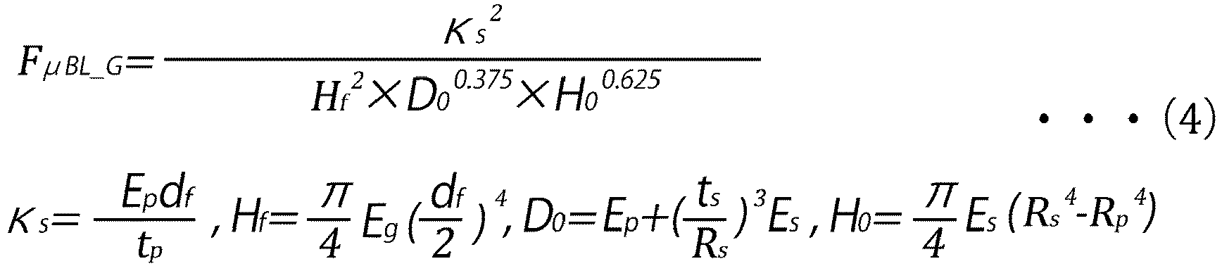
- Furthermore, the present inventor has conducted further research and found that when the value of the aforementioned microbend loss characteristic factor is 2.6 ([GPa-1 ·µm-10.5·dB/turn] ·10-27), the value of the sandpaper tension winding loss increase is a value slightly smaller than 0.6 dB/km. As described above, the value of the microbend loss characteristic factor has a substantially positive slope proportional relationship with the value of sandpaper tension winding loss increase. Therefore, by setting the value of the microbend loss characteristic factor of the optical fiber to 2.6 ([GPa-1·µm-10.5.dB/turn] ·10-27)or less, the microbend loss can be suppressed to the extent that the required characteristics of the tape slot type cable are satisfied.
- As described above, the
optical fiber 10 of the present embodiment is formed so that the value of the microbend loss characteristic factor FµBL_GO is 2.6 ([GPa-1.µm-10.5.dB/turn] ·10-27) or less. Therefore, in theoptical fiber 10 of the present embodiment, the microbend loss can be suppressed to the extent that the required characteristics of the tape slot type cable are satisfied. Therefore, theoptical fiber cable 1 using theoptical fiber 10 can exhibit favorable optical characteristics. - Furthermore, as described above, in the
optical fiber 10 of the present embodiment, even when the outside diameter df of theglass portion 13 is made smaller than 125 µm or the coating thickness t is made smaller than 60 µm, because parameters other than the outside diameter df of the glass portion and the coating thickness t are adjusted so that the value of the microbend loss characteristic factor FµBL_GO is 2.6 ([GPa-1·µm-10.5.dB/turn] ·10-27) or less, the microbend loss can be suppressed to the extent that the required characteristics of the tape slot type cable are satisfied. Here, as shown inFIG. 3 , the outside diameter 2Rs of theoptical fiber 10 is represented by
optical fiber 10 whose diameter is reduced and microbend loss is suppressed in this way, a tape slot type cable having excellent optical characteristics that realizes an increase in the number of cores and a small size can be configured. - Next, the second embodiment will be described with reference to
FIG. 4. FIG. 4 is a diagram schematically showing a structure of a cross section perpendicular to a longitudinal direction of anoptical fiber cable 2 according to the present embodiment. Note that the same or equivalent components as those of the first embodiment are designated by the same reference numerals and duplicated description will be omitted unless otherwise specified. - As shown in
FIG. 4 , theoptical fiber cable 2 of the present embodiment has the same configuration as theoptical fiber cable 1 of the first embodiment in thattape core wires 4 having substantially the same configuration as that of the first embodiment are accommodated inside. However, theoptical fiber cable 2 is mainly different from theoptical fiber cable 1 on the points described below. - The
optical fiber cable 1 is a tape slot type cable (RSCC) as described above. On the other hand, as shown inFIG. 4 , theoptical fiber cable 2 of the present embodiment does not have the holdingbody 5. That is, theoptical fiber cable 2 is a so-called small-diameter high-density cable (UHDC: Ultra-High Density Cable) in which the tape core wires are not accommodated in the slots of the holding body but are directly accommodated in the sheath. That is, anaccommodation space 3S is formed inside thesheath 3 of theoptical fiber cable 2, and a plurality oftape core wires 4 are arranged in theaccommodation space 3S. Note that thetensile strength bodies 6 may be embedded in thesheath 3 of theoptical fiber cable 2 at positions facing each other across the center of theoptical fiber cable 2. - Furthermore, as described above, the
tape core wire 4 of the present embodiment has substantially the same configuration as thetape core wire 4 of the first embodiment. However, the value of the microbend loss characteristic factor FµBL_GO of theoptical fiber 10 included in thetape core wire 4 of the present embodiment is 1.3 ([GPa-1·µm-10.5.dB/turn] ·10-27) or less for the reason described later. - Since the small-diameter high-density cable such as the
optical fiber cable 2 does not have the holdingbody 5 as described above and is slotless, thetape core wires 4 can be densely arranged in theaccommodation space 3S of thesheath 3. Therefore, a large number of tape core wires can be accommodated as compared with the tape slot type cable such as theoptical fiber cable 1. - On the other hand, in the small-diameter high-density cable, since many tape core wires are densely arranged in one place as described above, a large lateral pressure tends to be applied to the optical fiber as compared with the tape slot type cable. Therefore, in the small-diameter high-density cable, it is recommended to use an optical fiber having a smaller microbend loss than the optical fiber used for the tape slot type cable. In view of the above, the small-diameter high-density cable has the required characteristics that the value of the aforementioned sandpaper tension winding loss increase is 0.34 dB/km or less.
- The present inventor has calculated the value of the microbend loss characteristic factor FµBL_GO corresponding to the value (0.34 dB/km) of the sandpaper tension winding loss increase on the basis of the aforementioned formulae (2) to (4) and found that the value is 1.3 ([GPa-1· µm-10.5.dB/turn] ·10-27). That is, it has been found that by setting the value of the microbend loss characteristic factor FµBL_GO to 1.3 ([GPa-1·µm-10.5.dB/turn] ·10-27) or less, the microbend loss can be suppressed to the extent that the required characteristics of the small-diameter high-density cable are satisfied.
- As described above, the
optical fiber 10 of the present embodiment is configured so that the aforementioned various parameters are adjusted so that the value of the microbend loss characteristic factor FµBL_GO is 1.3 ([GPa-1.µm-10.5.dB/turn] ·10-27) or less. Therefore, the microbend loss can be suppressed to the extent that the required characteristics of the small-diameter high-density cable are satisfied. Therefore, theoptical fiber cable 2 using theoptical fiber 10 can exhibit favorable optical characteristics. - Furthermore, as described above, in the
optical fiber 10 of the present embodiment, even when theoptical fiber 10 has a reduced diameter by making the outside diameter df of theglass portion 13 smaller than 125 µm and the coating thickness t smaller than 57.5 µm, the microbend loss can be suppressed to the extent that the required characteristics of the small-diameter high-density cable are satisfied. Therefore, by using theoptical fiber 10 whose diameter is reduced in this way, a small-diameter high-density cable having excellent optical characteristics that realizes an increase in the number of cores and a small size can be configured. - Next, the reason why the outside diameter df of the
glass portion 13 can be small, the reason why the coating thickness of theoptical fiber 10 can be small, the reason why the outside diameter of theoptical fiber 10 can be small, and the like will be described. - The present inventor performed the following Examples 1 to 48 in order to verify the relationship between the value of the microbend loss characteristic factor FµBL_GO and the value of the sandpaper tension winding loss increase αµBL. Note that aspects for carrying out the present invention are not limited to Examples 1 to 48.
- The present inventor
prepared Samples 1 to 22 of optical fiber in which the aforementioned various parameters were changed, measured the value of sandpaper tension winding loss increase for each ofSamples 1 to 22, and calculated the value of the microbend loss characteristic factor FµBL_GO on the basis of the aforementioned formulae (2) to (4). The optical fiber ofSample 1 is the optical fiber of Example 1, and the optical fiber ofSample 2 is the optical fiber of Example 2. Thus, the sample numbers of the optical fibers correspond to the numbers of the Examples. Note that the optical fiber of Sample 8 is an optical fiber generally used for an optical fiber cable constituting the communication infrastructures, and has an outside diameter of the glass portion of 125 µm and a coating thickness of 57.5 µm. The optical fiber of Sample 8 may be referred to as the "general optical fiber". - The test for sandpaper tension winding loss increase was performed in the manner described below. That is, first, sandpaper (SiC having an average particle diameter of 50 µm (for example, model number #360)) was wound around the bobbin body portion having a body diameter of 380 mm, and one layer of optical fiber wire was wound therearound at 100 gf, and light having a wavelength of 1550 nm was caused to propagate. The transmission loss at this time was measured. Thereafter, the optical fiber wire was unwound from the bobbin, light having a wavelength of 1550 nm was caused to propagate with almost no tension applied, and the transmission loss was measured. Then, the difference between these transmission losses was obtained, and the value of this difference was defined as sandpaper tension winding loss increase αµBL.
- Tables 1 to 5 below show the parameter specifications for each of
Samples 1 to 22, the values of the microbend loss characteristic factor FµBL_GO for each ofSamples 1 to 22, and the values of sandpaper tension winding loss increase αµBL for each ofSamples 1 to 22. - Note that in Tables 1 to 5 below and Tables 7 to 10 described below, mode field diameter (MFD), cutoff wavelength, macrobend loss, and the like are as described below. The mode field diameter is the mode field diameter of light in the LP01 mode when light having a wavelength of 1310 nm is caused to propagate through the optical fiber.
- Note that the aforementioned mode field diameter is expressed by Petermann II definition formula (formula (5) below) in ITU-T Recommendation G.650.1. Here, E(r) represents the electric field strength at the point where the distance from the central axis of the optical fiber is r.

- Furthermore, the aforementioned cutoff wavelength indicates the minimum wavelength at which the high-order mode is sufficiently attenuated. This high-order mode refers to, for example, LP11 mode. Specifically, it is the minimum wavelength at which the loss of the high-order mode is 19.3 dB. The cutoff wavelength includes a fiber cutoff wavelength and a cable cutoff wavelength, and can be measured by, for example, the measurement method described in ITU-T Recommendation G.650. The cutoff wavelengths described in Tables 1 to 5 are cable cutoff wavelengths. Furthermore, the MAC value is the ratio of the mode field diameter 2w at a wavelength of 1310 nm to the cable cutoff wavelength λcc, and is defined as 2w/λcc. Furthermore, the macrobend losses shown in Tables 1 to 5 are the bend loss of light caused by light having a wavelength of 1625 nm propagating through a bent portion formed when the optical fiber is bent with a radius of 10 mm. The unit "/turn" of macrobend loss means "per turn of optical fiber". Furthermore, the propagation constant difference is the difference between the propagation constant of light having a wavelength of 1550 nm in the waveguide mode and the propagation constant of light having a wavelength of 1550 in the radiation mode, and, in this experiment, is the difference between the propagation constant of light having a wavelength of 1550 nm in the LP01 mode and the propagation constant in the LP11 mode. The propagation constant was calculated using the two-dimensional finite element method described in Non-Patent Literature 4 (K. Saitoh and M. Koshiba, "Full-Vectorial Imaginary-Distance Beam Propagation Method Based on a Finite Element Scheme: Application to Photonic Crystal Fibers," IEEE J. Quant. Elect. vol. 38, pp. 927-933, 2002.) on the basis of the refractive index profile of a prototyped optical fiber. The zero dispersion wavelength refers to a wavelength at which the value of the wavelength dispersion becomes zero. Here, the wavelength dispersion is the sum of material dispersion and waveguide dispersion. Furthermore, the zero dispersion slope refers to the rate of change of wavelength dispersion with respect to the wavelength at the zero dispersion wavelength.
Table 1 Example 1 2 3 4 5 Outside diameter of glass portion(µm) 80 80 80 125 80 Outside diameter of primary coating layer(µm) 125 115 115 159 115 Outside diameter of secondary coating layer(µm) 156 152 164 193 153 Young's modulus of glass portion(GPa) 74 74 74 74 74 Young's modulus of primary coating layer(MPa) 0.2 0.2 0.2 0.5 0.2 Young's modulus of secondary coating layer(MPa) 1150 1400 1400 1150 1400 Thickness of primary coating layer(µm) 22.5 17.5 17.5 17 17.5 Thickness of secondary coating layer(µm) 15.5 18.5 24.5 17 19 Coating thickness(µm) 38 36 42 34 36.5 Bending rigidity of glass portion(MPa· µm4) 1.49X10¹¹ 1.49X10¹¹ 1.49X10¹¹ 8.87X10¹¹ 1.49X10¹¹ Bending rigidity of secondary coating layer(MPa· µm4) 1.97X10¹⁰ 2.47X10¹⁰ 3.77X10¹⁰ 4.22X10¹⁰ 2.56X10¹⁰ µ(a.u.) 3 3 3 3 3 s(MPa)
0.71 0.91 0.91 3.68 0.91 Deformation resistance of secondary coating layer(MPa) 9.22 20.39 37.54 6.79 21.65 F µBL_G(GPa-1·µm-10.5·10-27) 3.66 3.90 2.38 1.92 3.72 Mode field diameter(µm) 8.83 8.66 8.66 8.6 8.6 Cable cutoff wavelength(µm) 1.230 1.230 1.230 1.230 1.200 MAC value(a.u.) 7.18 7.04 7.04 6.99 7.17 Macrobend loss(dB/turn) 0.100 0.050 0.050 0.050 0.200 Propagation constant difference (rad/m) 12498 13182 13182 13066 11613 Zero dispersion wavelength(µm) 1.311 1.316 1.316 1.317 1.310 Zero dispersion slope(ps/km/nm2) 0.088 0.086 0.086 0.086 0.087 F µ BL_O(dB/turn) 0.72 0.35 0.35 0.35 1.43 F µ BL_GO ({GPa-1 · µ m-10.5·dB/turn}·10-27) 2.63 1.37 0.84 0.67 5.33 Sandpaper tension winding loss increase(dB/km) 0.85 0.46 0.3 0.22 0.98 Table 2 Example 6 7 8 9 10 Outside diameter of glass portion(µm) 80 125 125 80 80 Outside diameter of primary coating layer(µm) 115 159 190 113 113 Outside diameter of secondary coating layer(µm) 153 193 240 164 153 Young's modulus of glass portion(GPa) 74 74 74 114 74 Young's modulus of primary coating layer(MPa) 0.2 0.5 0.6 0.2 0.2 Young's modulus of secondary coating layer(MPa) 1150 1150 800 1150 1150 Thickness of primary coating layer(µm) 17.5 17 32.5 16.5 16.5 Thickness of secondary coating layer(µm) 19 17 25 25.5 20 Coating thickness(µm) 36.5 34 57.5 42 36.5 Bending rigidity of glass portion(MPa· µm4) 1.49X10" 8.87X10¹¹ 8.87X10¹¹ 2.29X10¹¹ 1.49X10¹¹ Bending rigidity of secondary coating layer(MPa· µm4) 2.11X10¹⁰ 4.22X10¹⁰ 7.91X10¹⁰ 3.16X10¹⁰ 2.17X10¹⁰ µ(a.u.) 3 3 3 3 3 s(MPa)0.91 3.68 2.31 0.97 0.97 Deformation resistance of secondary coating layer(MPa) 17.82 6.79 7.83 34.78 20.75 F µ BL_G(GPa-1·µ m-10-5·10-27) 4.53 1.92 0.48 1.29 4.72 Mode field diameter(µm) 8.48 8.5 8.55 8.51 8.47 Cable cutoff wavelength(µm) 1.209 1.203 1.197 1.287 1.330 MAC value(a.u.) 7.01 7.07 7.14 6.61 6.37 Macrobend loss(dB/turn) 0.200 0.091 0.133 0.013 0.035 Propagation constant difference (rad/m) 11403 11971 11623 14259 14296 Zero dispersion wavelength(µm) 1.313 1.313 1.313 1.309 1.309 Zero dispersion slope(ps/km/nm2) 0.085 0.086 0.086 0.091 0.091 F µBL_O(dB/turn) 1.40 0.65 0.95 0.09 0.22 F µ BL_GO ({GPa-1 · µm-10.5·dB/turn}.10-27) 6.35 1.24 0.47 0.11 1.05 Sandpaper tension winding loss increase(dB/km) 1.5 0.3 0.05 0.218 0.315 Table 3 Example 11 12 13 14 15 Outside diameter of glass portion (µ m) 80 80 80 80 90 Outside diameter of primary coating layer(µm) 114 114 115 115 121 Outside diameter of secondary coating layer(µm) 153 164 153 153 159 Young's modulus of glass portion(GPa) 74 74 74 74 74 Young's modulus of primary coating layer(MPa) 0.2 0.2 0.2 0.2 0.2 Young's modulus of secondary coating layer(MPa) 1150 1150 1150 1400 1150 Thickness of primary coating layer(µm) 17 17 17.5 17.5 15.5 Thickness of secondary coating layer(µm) 19.5 25 19 19 19 Coating thickness(µm) 36.5 42 36.5 36.5 34.5 Bending rigidity of glass portion(MPa· µm4) 1.49X10¹¹ 1.49X10¹¹ 1.49X10¹¹ 1.49X10¹¹ 2.38X10¹¹ Bending rigidity of secondary coating layer(MPa · µm4) 2.14X10¹⁰ 3.13X10¹⁰ 2.11X10¹⁰ 2.56X10¹⁰ 2.40X10¹⁰ µ(a.u.) 3 3 3 3 3 s(MPa)0.94 0.94 0.91 0.91 1.16 Deformation resistance of secondary coating layer(MPa) 19.25 32.79 17.82 21.65 15.90 F µ BL_G(GPa-1· µm-10-5·10-27) 4.61 2.98 4.53 3.72 2.74 Mode field diameter(µm) 8.47 8.5 8.36 8.4 8.52 Cable cutoff wavelength(µm) 1.357 1.367 1.174 1.188 1.221 MAC value(a.u.) 6.24 6.22 7.12 7.07 6.98 Macrobend loss(dB/turn) 0.010 0.010 0.080 0.040 0.040 Propagation constant difference (rad/m) 15223 15007 13198 15278 14687 Zero dispersion wavelength(µm) 1.309 1.309 1.310 1.310 1.309 Zero dispersion slope(ps/km/nm2) 0.091 0.091 0.089 0.089 0.091 F µ BL_O(dB/turn) 0.06 0.06 0.57 0.28 0.28 F µ BL_GO ({GPa-1 · µm-10.5·dB/turn}·10-27) 0.29 0.19 2.58 1.05 0.76 Sandpaper tension winding loss increase(dB/km) 0.231 0.289 0.57 0.27 0.197 Table 4 Example 16 17 18 19 20 Outside diameter of glass portion (µm) 90 90 80 80 80 Outside diameter of primary coating layer(µm) 121 121 115 115 115 Outside diameter of secondary coating layer(µm) 159 159 153 164 153 Young' s modulus of glass portion(GPa) 74 74 74 74 74 Young's modulus of primary coating layer(MPa) 0.2 0.2 0.2 0.2 0.2 Young's modulus of secondary coating layer(MPa) 1150 1150 1150 1150 1150 Thickness of primary coating layer(µm) 15.5 15.5 17.5 17.5 17.5 Thickness of secondary coating layer(µm) 19 19 19 24.5 19 Coating thickness(µm) 34.5 34.5 36.5 42 36.5 Bending rigidity of glass portion(MPa· µm4) 2.38X10¹¹ 2.38X10¹¹ 1.49X10¹¹ 1.49X10¹¹ 1.49X10¹¹ Bending rigidity of secondary coating layer(MPa ·µm4) 2.40X10¹⁰ 2.40X10¹⁰ 2.11X10¹⁰ 3.10X10¹⁰ 2.11X10¹⁰ µ(a.u.) 3 3 3 3 3 s(MPa)1.16 1.16 0.91 0.91 0.91 Deformation resistance of secondary coating layer(MPa) 15.90 15.90 17.82 30.87 17.82 F µ BL_G(GPa-1· µ m-10.5·10-27) 2.74 2.74 4.53 2.90 4.53 Mode field diameter(µm) 8.506 8.46 7.645 7.64 7.607 Cable cutoff wavelength(µm) 1.270 1.286 1.184 1.245 1.271 MAC value(a.u.) 6.70 6.58 6.46 6.14 5.99 Macrobend loss(dB/turn) 0.017 0.008 0.070 0.006 0.004 Propagation constant difference (rad/m) 14392 15187 12929 13865 14825 Zero dispersion wavelength(µm) 1.309 1.309 1.336 1.336 1.336 Zero dispersion slope(ps/km/nm2) 0.091 0.091 0.079 0.079 0.079 F µ BL_O(dB/turn) 0.11 0.05 0.45 0.04 0.02 F µ BL_GO ([GPa-1· µm-10.5·dB/turn} · 10-27) 0.31 0.14 2.05 0.11 0.11 Sandpaper tension winding loss increase(dB/km) 0.23 0.164 0.577 0.23 0.259 Table 5 Example 21 22 Outside diameter of glass portion (µm) 80 80 Outside diameter of primary coating layer(µm) 115 115 Outside diameter of secondary coating layer(µm) 153 153 Young's modulus of glass portion(GPa) 74 74 Young's modulus of primary coating layer(MPa) 0.2 0.2 Young's modulus of secondary coating layer(MPa) 1150 1400 Thickness of primary coating layer(µm) 17.5 17.5 Thickness of secondary coating layer(µm) 19 19 Coating thickness(µm) 36.5 36.5 Bending rigidity of glass portion(MPa · µm4) 1.49X10¹¹ 1.49X10¹¹ Bending rigidity of secondary coating layer(MPa· µm4) 2.11X10¹⁰ 2.56X10¹⁰ µ(a.u.) 3 3 s(MPa)0.91 0.91 Deformation resistance of secondary coating layer(MPa) 17.82 21.65 F µ BL_G(GPa-1·µm-10.5·10-27) 4.53 3.72 Mode field diameter(µm) 7.627 7.7 Cable cutoff wavelength(µm) 1.300 1.183 MAC value(a.u.) 5.87 6.51 Macrobend loss(dB/turn) 0.001 0.040 Propagation constant difference (rad/m) 15702 13192 Zero dispersion wavelength(µm) 1.336 1.339 Zero dispersion slope(ps/km/nm2) 0.079 0.079 F µ BL_O(dB/turn) 0.01 0.26 F µBL_GO ({GPa-1 · µm-10.5·dB/turn} · 10-27) 0.03 0.97 Sandpaper tension winding loss increase(dB/km) 0.165 0.334 - The present inventor plotted the values of the microbend loss characteristic factor FµBL_GO and the values of the sandpaper tension winding loss increase αµBL of each of
Samples 1 to 22 with respect to a coordinate system in which the value of microbend loss characteristic factor FµBL_GO is on the horizontal axis (X-axis) and the value of sandpaper tension winding loss increase αµBL is on the vertical axis (Y-axis). As a result, the scatter diagram shown inFIG. 5 was obtained. When the function was obtained from this scatter diagram using the least-squares method, a linear function with a positive slope represented by the formula (6) below was obtained. Furthermore, the correlation coefficient of the data inFIG. 5 was 89% or more.
- That is, it was found that the value of the microbend loss characteristic factor FµBL_GO and the value of the sandpaper tension winding loss increase αµBL had a high correlation, and specifically the value of the microbend loss characteristic factor FµBL_GO and the value of the sandpaper tension winding loss increase αµBL had a proportional relationship having a generally positive slope.
- By the way, as described above, the tape slot type cable (RSCC) has the required characteristics that the value of the sandpaper tension winding loss increase αµBL is 0.60 (dm/km) or less. Furthermore, the small-diameter high-density cable (UHDC) has the required characteristics that the value of the sandpaper tension winding loss increase αµBL is 0.34 (dm/km) or less. Therefore, Table 6 below indicates the values of the microbend loss characteristic factor FµBL_GO, the values of the sandpaper tension winding loss increase αµBL, the pass/fail of the required characteristics of the tape slot type cable (RSCC), and the pass/fail of the required characteristics of the small-diameter high-density cable (UHDC) of Examples 1 to 22. Note that in Table 6, Y means that the required characteristics are satisfied, and N means that the required characteristics are not satisfied.
Table 6 Example αµ BL (dB/km) F µ BL_GO ({GPa-1 · µ m-10.5 · dB/turn}· 10-27) Application to RSCC (F µ BL_GO≦2.6) Application to UHDC (F µBL_GO≦1.3) 21 0.17 0.03 Y Y 19 0.23 0.11 Y Y 20 0.26 0.11 Y Y 9 0.22 0.11 Y Y 17 0.16 0.14 Y Y 12 0.29 0.19 Y Y 11 0.23 0.29 Y Y 16 0.23 0.31 Y Y 8 0.05 0.46 Y Y 4 0.22 0.67 Y Y 15 0.20 0.76 Y Y 3 0.30 0.84 Y Y 22 0.33 0.97 Y Y 10 0.32 1.05 Y Y 14 0.27 1.05 Y Y 7 0.30 1.24 Y Y 2 0.46 1.37 Y N 18 0.58 2.05 Y N 13 0.57 2.58 Y N 1 0.85 2.63 N N 5 0.98 5.33 N N 6 1.50 6.35 N N - From Table 6, it was found that when the value of the microbend loss characteristic factor FµBL_GO is 2.6 ([GPa-1·µm-10.5·dB/turn] ·10-27) or less, the value of the sandpaper tension winding loss increase αµBL tends to be approximately 0.60 or less and when the value of the microbend loss characteristic factor FµBL_GO is larger than 2.6 ([GPa-1· µm-10.5·dB/turn] ·10-27), the value of the sandpaper tension winding loss increase αµBL tends to exceed 0.60. In other words, it was found that the required characteristics of the tape slot type cable can be satisfied by adjusting the values of the parameters described in Tables 1 to 5 described above so that the value of the microbend loss characteristic factor FµBL_GO is 2.6 ([GPa-1·µm-10.5·dB/turn] ·10-27) or less.
- Furthermore, it was found that when the value of the microbend loss characteristic factor FµBL_GO is 1.3 ([GPa-1·µm-10.5·dB/turn]·10-27) or less, the value of the sandpaper tension winding loss increase αµBL tends to be approximately 0.34 or less and when the value of the microbend loss characteristic factor FµBL_GO is larger than 1.3 ([GPa-1· µm-10.5·dB/turn] ·10-27), the value of the sandpaper tension winding loss increase αµBL tends to exceed 0.34. In other words, it was found that in addition to the required characteristics of the tape slot type cable, the required characteristics of the small-diameter high-density cable can be satisfied by adjusting the values of the parameters described in Tables 1 to 5 described above so that the value of the microbend loss characteristic factor FµBL_GO is 1.3 ([GPa-1·µm-10.5·dB/turn] ·10-27) or less.
- Specifically, among
Samples 1 to 22, the samples satisfying the required characteristics of the tape slot type cable were thesamples excluding Samples - Furthermore, among the samples satisfying at least the required characteristics of the tape slot type cable among
Samples 1 to 22, it was found that thesamples excluding Samples Samples Samples 15 to 17 have an outside diameter of the glass portion of 90 µm. That is, it was found that, by adjusting the parameters as inSamples - Furthermore, it was found that the samples, excluding Sample 8, satisfying at least the required characteristics of the tape slot type cable among
Samples 1 to 22 have a coating thickness smaller than the coating thickness (approximately 57.5 µm) of the general optical fiber. Specifically, it was found thatSamples Samples Sample 2 has a coating thickness of 36.0 µm,Samples 15 to 17 have a coating thickness of 34.5 µm, andSamples Samples 2 to 4, 7, and 9 to 22, an optical fiber that satisfies at least the required characteristics of the tape slot type cable and has the coating thickness smaller than that of the general optical fiber can be formed. - As described above, it was found that, among
Samples 1 to 22, thesamples excluding Samples - Furthermore, the optical fibers of
Samples 1 to 22 have an MFD of 7.6 µm or more. When the MFD is too small, an MFD mismatch can occur when connection to a general-purpose optical fiber is established. However, when the MFD of the optical fiber is 7.6 µm or more, the MFD mismatch when connection to a general-purpose optical fiber is established can be small. Therefore, the occurrence of connection loss can be effectively suppressed. - Moreover, the optical fibers of
Samples 5 to 8 meet the international standard ITU-.G.657.A1. That is, the MFD at a wavelength of 1310 nm is 8.2 µm or more and 9.6 µm or less, the cable cutoff wavelength is 1260 nm or less, the zero dispersion wavelength is 1300 to 1324 nm, the zero dispersion slope is 0.073 ps/km/nm or more and 0.092 ps/km/nm or less, and the macrobend loss at a wavelength of 1625 nm by bending at a radius of 10 mm is 1.5 dB/turn or less. Furthermore, the optical fibers ofSamples 1 to 4 satisfy ITU-T.G.657.A2. That is, the MFD at a wavelength of 1310 nm is 8.2 µm or more and 9.6 µm or less, the cable cutoff wavelength is 1260 nm or less, the zero dispersion wavelength is 1300 nm or more and 1324 nm or less, the zero dispersion slope is 0.073 ps/km/nm or more and 0.092 ps/km/nm or less, and the macrobend loss at a wavelength of 1625 nm by bending at a radius of 10 mm is 0.2 dB/turn or less. Furthermore, the optical fibers ofSamples 13 to 15 satisfy ITU-T.G.657.B3. That is, the MFD at a wavelength of 1310 nm is 8.2 µm or more and 9.6 µm or less, the cable cutoff wavelength is 1260 nm or less, the zero dispersion wavelength is 1300 nm or more and 1324 nm or less, the zero dispersion slope is 0.073 ps/km/nm or more and 0.092 ps/km/nm or less, and the macrobend loss at a wavelength of 1625 nm by bending at a radius of 10 mm is 0.1 dB/turn or less. - Furthermore, the present inventor determined the values of the microbend loss characteristic factor FµBL_GO of Samples 23 to 28 of optical fiber adjusted as indicated in Table 7 below on the assumption of an optical fiber having the same optical characteristics as Samples 16, 17, and 19, specifically, the same MFD, cable cutoff wavelength, MAC value, macrobend loss (bending loss), propagation constant difference, zero dispersion wavelength, and zero dispersion slope as those samples, the same thickness of the primary coating layer and thickness of the secondary coating layer as those of Sample 19, and an outside diameter of the glass portion of 65 µm.
Table 7 Example 23 24 25 26 27 28 Outside diameter of glass portion (µm) 65 65 65 65 65 65 Outside diameter of primary coating layer(µm) 100 100 100 100 100 100 Outside diameter of secondary coating layer(µm) 149 149 149 149 149 149 Young's modulus of glass portion(GPa) 74 74 74 74 74 74 Young's modulus of primary coating layer(MPa) 0.2 0.2 0.2 0.2 0.2 0.2 Young's modulus of secondary coating layer(MPa) 1400 1150 1400 1150 1400 1150 Thickness of primary coating layer(µm) 17.5 17.5 17.5 17.5 17.5 17.5 Thickness of secondary coating layer(µm) 24.5 24.5 24.5 24.5 24.5 24.5 Coating thickness(µm) 42 42 42 42 42 42 Bending rigidity of glass portion(MPa· µm4) 6.48X10¹⁰ 6.48X10¹⁰ 6.48X10¹⁰ 6.48X10¹⁰ 6.48X10¹⁰ 6.48X10¹⁰ Bending rigidity of secondary coating layer(MPa·µm4) 2.70X10¹⁰ 2.22X10¹⁰ 2.70X10¹⁰ 2.22X10¹⁰ 2.70X10¹⁰ 2.22X10¹⁰ µ (a.u.) 3 3 3 3 3 3 s(MPa)0.74 0.74 0.74 0.74 0.74 0.74 Deformation resistance of secondary coating layer(MPa) 49.99 41.10 49.99 41.10 49.99 41.10 Fµ BL_G(GPa-1·µm-10.5·10-27) 9.15 11.14 9.15 11.14 9.15 11.14 Mode field diameter(µm) 7.64 7.64 8.506 8.506 8.46 8.46 Cable cutoff wavelength(µm) 1.245 1.245 1.270 1.270 1.286 1.286 MAC value(a.u.) 6.14 6.14 6.70 6.70 6.58 6.58 Macrobend loss(dB/turn) 0.006 0.006 0.017 0.017 0.008 0.008 Propagation constant difference (rad/m) 13865 13865 14392 14392 15187 15187 Zero dispersion wavelength(µm) 1.336 1.336 1.309 1.309 1.309 1.309 Zero dispersion slope(ps/km/nm2) 0.079 0.079 0.091 0.091 0.091 0.091 F µ BL_O(dB/turn) 0.04 0.04 0.11 0.11 0.05 0.05 F µ BL_GO ([GPa-1· µm-10-5·dB/turn} · 10-27) 0.34 0.41 1.04 1.27 0.48 0.59 Application to RSCC Y Y Y Y Y Y Application to UHDC Y Y Y Y Y Y - As indicated in Table 7, each of Samples 23 to 28 has an outside diameter of the glass portion of 65 µm and a coating thickness of 42 µm. Furthermore, it was found that the values of the microbend loss characteristic factor FµBL_GO of Samples 23 to 28 are all 2.6 ([GPa-1 · µm-10-5·dB/turn] ·10-27) or less, and Samples 23 to 28 satisfy the required characteristics of the tape slot type cable. Furthermore, it was found that the values of the microbend loss characteristic factor FµBL_GO of Samples 23 to 28 are all 1.3 ([GPa-1 µm10.5·dB/turn] · 10-27) or less, and Samples 23 to 28 satisfy the required characteristics of the small-diameter high-density cable in addition to the required characteristics of the tape slot type cable.
- Furthermore, the present inventor determined the values of the microbend loss characteristic factor FµBL_GO of Samples 29 to 36 of optical fiber adjusted as indicated in Tables 8 and 9 below on the assumption of an optical fiber having the same optical characteristics as
Samples 15, 16, 17, and 19, specifically, the same MFD, cable cutoff wavelength, MAC value, macrobend loss, propagation constant difference, zero dispersion wavelength, and zero dispersion slope as those samples, the same thickness of the primary coating layer and thickness of the secondary coating layer as those of Example 19, and an outside diameter of the glass portion of 70 µm.Table 8 Example 29 30 31 32 Outside diameter of glass portion (µm) 70 70 70 70 Outside diameter of primary coating layer(µm) 105 105 105 105 Outside diameter of secondary coating layer(µm) 154 154 154 154 Young's modulus of glass portion(GPa) 74 74 74 74 Young's modulus of primary coating layer(MPa) 0.2 0.2 0.15 0.15 Young's modulus of secondary coating layer(MPa) 1400 1150 1400 1150 Thickness of primary coating layer(µm) 17.5 17.5 17.5 17.5 Thickness of secondary coating layer(µm) 24.5 24.5 24.5 24.5 Coating thickness(µm) 42 42 42 42 Bending rigidity of glass portion(MPa· µm4) 8.72X10¹⁰ 8.72X10¹⁰ 8.72X10¹⁰ 8.72X10¹⁰ Bending rigidity of secondary coating layer(MPa· µm4) 3.03X10¹⁰ 2.49X10¹⁰ 3.03X10¹⁰ 2.49X10¹⁰ µ(a.u.) 3 3 3 3 κs (MPa) 0.80 0.80 0.60 0.60 Deformation resistance of secondary coating layer(MPa) 45.30 37.24 45.25 37.19 F µBL_G(GPa-1 ·µm-10.5 · 10-27) 5.66 6.89 3.19 3.88 Mode field diameter(µm) 7.64 7.64 8.52 8.52 Cable cutoff wavelength(µm) 1.245 1.245 1.221 1.221 MAC value(a.u.) 6.14 6.14 6.98 6.98 Macrobend loss(dB/turn) 0.006 0.006 0.040 0.040 Propagation constant difference (rad/m) 13865 13865 14687 14687 Zero dispersion wavelength(µm) 1.336 1.336 1.309 1.309 Zero dispersion slope(ps/km/nm2) 0.079 0.079 0.091 0.091 F µ BL_o(dB/turn) 0.04 0.04 0.28 0.28 Fµ BL_GO ({GPa-1 · µm-10.5·dB/turn}·10-27) 0.21 0.25 0.89 1.08 Application to RSCC Y Y Y Y Application to UHDC Y Y Y Y Table 9 Example 33 34 35 36 Outside diameter of glass portion (µm) 70 70 70 70 Outside diameter of primary coating layer(µm) 105 105 105 105 Outside diameter of secondary coating layer(µm) 154 154 154 154 Young's modulus of glass portion(GPa) 74 74 74 74 Young's modulus of primary coating layer(MPa) 0.2 0.2 0.2 0.2 Young's modulus of secondary coating layer(MPa) 1400 1150 1400 1150 Thickness of primary coating layer(µm) 17.5 17.5 17.5 17.5 Thickness of secondary coating layer(µm) 24.5 24.5 24.5 24.5 Coating thickness(µm) 42 42 42 42 Bending rigidity of glass portion(MPa· µm4) 8.72X10¹⁰ 8.72X10¹⁰ 8.72X10¹⁰ 8.72X10¹⁰ Bending rigidity of secondary coating laver(MPa·µm4) 3.03X10¹⁰ 2.49X10¹⁰ 3.03X10¹⁰ 2.49X10¹⁰ µ(a.u.) 3 3 3 3 κs (MPa) 0.80 0.80 0.80 0.80 Deformation resistance of secondary coating layer(MPa) 45.30 37.24 45.30 37.24 Fµ BL_G(GPa-1·µm-10.5 ·10-27) 5.66 6.89 5.66 6.89 Mode field diameter(µm) 8.506 8.506 8.46 8.46 Cable cutoff wavelength(µm) 1.270 1.270 1.286 1.286 MAC value(a.u.) 6.70 6.70 6.58 6.58 Macrobend loss(dB/turn) 0.017 0.017 0.008 0.008 Propagation constant difference (rad/m) 14392 14392 15187 15187 Zero dispersion wavelength(µm) 1.309 1.309 1.309 1.309 Zero dispersion slope(ps/km/nm2) 0.091 0.091 0.091 0.091 Fµ BL_o(dB/turn) 0.11 0.11 0.05 0.05 Fµ BL_GO ([GPa-1· µm-10.5·dB/turn}·10-27) 0.64 0.78 0.30 0.36 Application to RSCC Y Y Y Y Application to UHDC Y Y Y Y - As indicated in Tables 8 and 9, each of Samples 29 to 36 has an outside diameter of the glass portion of 70 µm and a coating thickness of 42 µm. Furthermore, it was found that the values of the microbend loss characteristic factor FµBL_GO of Samples 29 to 36 are all 2.6 ([GPa-1·µm-10.5·dB/turn]·10-27) or less, and Samples 29 to 36 satisfy the required characteristics of the tape slot type cable. Furthermore, it was found that the values of the microbend loss characteristic factor FµBL_GO of Samples 29 to 36 are all 1.3 ([GPa-1 µm10.5·dB/turn] · 10-27) or less, and Samples 29 to 36 satisfy the required characteristics of the small-diameter high-density cable in addition to the required characteristics of the tape slot type cable.
- Furthermore, the present inventor determined the values of the microbend loss characteristic factor FµBL_GO of Samples 37 to 42 of optical fiber adjusted as indicated in Table 10 below on the assumption of an optical fiber having the same optical characteristics as
Samples 15, 17, and 19, specifically, the same MFD, cable cutoff wavelength, MAC value, macrobend loss, propagation constant difference, zero dispersion wavelength, and zero dispersion slope as those samples, the same thickness of the primary coating layer and thickness of the secondary coating layer as those of Example 19, and an outside diameter of the glass portion of 75 µm.Table 10 Example 37 38 39 40 41 42 Outside diameter of glass portion (µm) 75 75 75 75 75 75 Outside diameter of primary coating layer(µm) 110 110 110 110 110 110 Outside diameter of secondary coating layer(µm) 159 159 159 159 159 159 Young's modulus of glass portion(GPa) 74 74 74 74 74 74 Young's modulus of primary coating layer(MPa) 0.2 0.2 0.2 0.2 0.2 0.2 Young's modulus of secondary coating layer(MPa) 1400 1150 1400 1150 1400 1150 Thickness of primary coating layer(µm) 17.5 17.5 17.5 17.5 17.5 17.5 Thickness of secondary coating layer(µm) 24.5 24.5 24.5 24.5 24.5 24.5 Coating thickness(µm) 42 42 42 42 42 42 Bending rigidity of glass portion(MPa· µm4) 1.15X10¹¹ 1.15X10" 1.15X10" 1.15X10¹¹ 1.15X10¹¹ 1.15X10¹¹ Bending rigidity of secondary coating layer(MPa·µm4) 3.39X10¹⁰ 2.78X10¹⁰ 3.39X10¹⁰ 2.78X10¹⁰ 3.39X10¹⁰ 2.78X10¹⁰ µ(a.u.) 3 3 3 3 3 3 κs (MPa) 0.86 0.86 0.86 0.86 0.86 0.86 Deformation resistance of secondary coating layer(MPa) 41.18 33.86 41.18 33.86 41.18 33.86 FµBL_G(GPa-1·µm-10.5·10-27) 3.62 4.40 3.62 4.40 3.62 4.40 Mode field diameter(µm) 7.64 7.64 8.52 8.52 8.46 8.46 Cable cutoff wavelength(µm) 1.245 1.245 1.221 1.221 1.286 1.286 MAC value(a.u.) 6.14 6.14 6.98 6.98 6.58 6.58 Macrobend loss(dB/turn) 0.006 0.006 0.040 0.040 0.008 0.008 Propagation constant difference (rad/m) 13865 13865 14687 14687 15187 15187 Zero dispersion wavelength(µm) 1.336 1.336 1.309 1.309 1.309 1.309 Zero dispersion slope(ps/km/nm2) 0.079 0.079 0.091 0.091 0.091 0.091 Fµ BL_o(dB/turn) 0.04 0.04 0.28 0.28 0.05 0.05 Fµ BL_GO ({GPa-1 · µm-10.5·dB/turn}·10-27) 0.13 0.16 1.01 1.23 0.19 0.23 Application to RSCC Y Y Y Y Y Y Application to UHDC Y Y Y Y Y Y - As indicated in Table 10, each of Samples 37 to 42 has an outside diameter of the glass portion of 75 µm and a coating thickness of 42 µm. Furthermore, it was found that the values of the microbend loss characteristic factor FµBL_GO of Samples 37 to 42 are all 2.6 ([GPa-1 ·µm-10.5 ·dB/turn] · 10-27) or less, and Samples 37 to 42 satisfy the required characteristics of the tape slot type cable. Furthermore, it was found that the values of the microbend loss characteristic factor FµBL_GO of Samples 37 to 42 are all 1.3 ([GPa-1·µm10.5·dB/turn] · 10-27) or less, and Samples 37 to 42 satisfy the required characteristics of the small-diameter high-density cable in addition to the required characteristics of the tape slot type cable.
- Furthermore, the present inventor determined the values of the microbend loss characteristic factor FµBL_GO of Samples 43 to 48 of optical fiber adjusted as indicated in Table 11 below on the assumption of an optical fiber having the same optical characteristics as
Samples 15, 17, and 19, specifically, the same MFD, cable cutoff wavelength, MAC value, macrobend loss, propagation constant difference, zero dispersion wavelength, and zero dispersion slope as those samples, an outside diameter of the secondary coating layer of 125 µm, and an outside diameter of the glass portion of 80 µm.Table 11 Example 43 44 45 46 47 48 Outside diameter of glass portion (µm) 80 80 80 80 80 80 Outside diameter of primary coating layer(µm) 100 100 100 100 100 100 Outside diameter of secondary coating layer(µm) 125 125 125 125 125 125 Young's modulus of glass portion(GPa) 74 74 74 74 74 74 Young's modulus of primary coating layer(MPa) 0.15 0.15 0.15 0.15 0.15 0.15 Young's modulus of secondary coating layer(MPa) 1400 1150 1400 1150 1400 1150 Thickness of primary coating layer(µm) 10 10 10 10 10 10 Thickness of secondary coating layer(µm) 12.5 12.5 12.5 12.5 12.5 12.5 Coating thickness(µm) 22.5 22.5 22.5 22.5 22.5 22.5 Bending rigidity of glass portion(MPa·µm4) 1.49X10¹¹ 1.49X10" 1.49X10¹¹ 1.49X10¹¹ 1.49X10¹¹ 1.49X10¹¹ Bending rigidity of secondary coating layer(MPa·µm4) 9.91X10⁹ 8.14X10⁹ 9.91X10⁹ 8.14X10⁹ 9.91X10⁹ 8.14X10⁹ µ(a.u.) 3 3 3 3 3 3 κs (MPa) 1.20 1.20 1.20 1.20 1.20 1.20 Deformation resistance of secondary coating layer(MPa) 11.35 9.35 11.35 9.35 11.35 9.35 Fµ BL_G(GPa-1·µm-10.5·10-27) 14.80 17.99 14.80 17.99 14.80 17.99 Mode field diameter(µm) 7.64 7.64 8.52 8.52 8.46 8.46 Cable cutoff wavelength(µm) 1.245 1.245 1.221 1.221 1.286 1.286 MAC value(a.u.) 6.14 6.14 6.98 6.98 6.58 6.58 Macrobend loss(dB/turn) 0.006 0.006 0.040 0.040 0.008 0.008 Propagation constant difference (rad/m) 13865 13865 14687 14687 15187 15187 Zero dispersion wavelength(µm) 1.336 1.336 1.309 1.309 1.309 1.309 Zero dispersion slope(ps/km/nm2) 0.079 0.079 0.091 0.091 0.091 0.091 Fµ BL_O(dB/turn) 0.04 0.04 0.28 0.28 0.05 0.05 Fµ BL_GO ({GPa-1·µm-10.5·dB/turn}·10-27) 0.54 0.66 4.13 5.02 0.78 0.95 Application to RSCC Y Y N N Y Y Application to UHDC Y Y N N Y Y - As indicated in Table 11, each of Samples 43 to 48 has an outside diameter of the glass portion of 80 µm, an outside diameter of the secondary coating layer of 125 µm, and a thickness of the coating layer of 22.5 µm. Furthermore, it was found that the values of the microbend loss characteristic factor FµBL_GO of Samples 43, 44, 47, and 48 are all 1.3 ([GPa-1·µm10.5·dB/turn] ·10-27) or less, and Samples 43, 44, 47, and 48 satisfy the required characteristics of the small-diameter high-density cable in addition to the required characteristics of the tape slot type cable. Note that similar to Samples 43, 44, 47 and 48, Samples 45 and 46 have an outside diameter of the glass portion of 80 µm, an outside diameter of the secondary coating layer of 125 µm, and a thickness of the coating layer of 22.5 µm, but the values of the microbend loss characteristic factor FµBL_GO exceed 2.6 ([GPa-1 ·µm-10.5·dB/turn] ·10-27), and do not satisfy the required characteristics of the tape slot type cable or the required characteristics of the small-diameter high-density cable.
- Although the present invention has been described above by taking the aforementioned embodiments as an example, the present invention is not limited thereto.
- For example, in the first and second embodiments described above, the example in which the secondary coating layer is the outermost layer of the optical fiber has been described. However, even when a colored layer is further provided as a third coating layer on the outer periphery of the secondary coating layer, the secondary coating layer and the colored layer can be applied to the present invention as a second coating layer, i.e., the secondary coating layer as long as the Young's modulus of the colored layer is not significantly different from the Young's modulus of the secondary coating layer.
- According to the present invention, an optical fiber capable of suppressing microbend loss is provided, and can be used in a field such as a communication infrastructure.
Claims (16)
- An optical fiber comprising a glass portion including a core and a clad surrounding the core, a primary coating layer covering the clad, and a secondary coating layer covering the primary coating layer,
wherein
a value of microbend loss characteristic factor FµBL_GO ([GPa-1 ·µm-10.5 · dB/turn] ·10-27) represented by
geometry microbend loss characteristic FµBL_G (GPa-1·µm-10.5·10-27) of the optical fiber represented by

optical microbend loss characteristic FµBL_O (dB/turn) of the optical fiber represented by
is 2.6 ([GPa-1 µm10.5·dB/turn] ·10-27) or less. - The optical fiber according to claim 1, wherein the value of the microbend loss characteristic factor is 1.3 ([GPa-1·µm-10.5·dB/turn]·10-27) or less.
- The optical fiber according to claim 1 or 2, wherein a coating thickness of a sum of the thickness of the primary coating layer and the thickness of the secondary coating layer is 42.0 µm or less.
- The optical fiber according to claim 3, wherein the coating thickness is 38.0 µm or less.
- The optical fiber according to claim 4, wherein the coating thickness is 36.5 µm or less.
- The optical fiber according to claim 5, wherein the coating thickness is 34.5 µm or less.
- The optical fiber according to claim 6, wherein the coating thickness is 34.0 µm or less.
- The optical fiber according to any one of claims 3 to 7, wherein the outside diameter of the glass portion is 65 µm or more and 100 µm or less.
- The optical fiber according to claim 8, wherein the outside diameter of the glass portion is 90 µm or less.
- The optical fiber according to claim 9, wherein the outside diameter of the glass portion is 80 µm or less.
- The optical fiber according to claim 10, wherein the outside diameter of the glass portion is 75 µm or less.
- The optical fiber according to claim 11, wherein the outside diameter of the glass portion is 70 µm or less.
- The optical fiber according to any of claims 3 to 11, wherein the mode field diameter of light having a wavelength of 1310 nm is 7.6 µm or more and 8.7 µm or less, the cable cutoff wavelength is 1260 nm or less, zero dispersion wavelength is 1300 nm or more and 1324 nm or less, and zero dispersion slope is 0.073 ps/km/nm or more and 0.092 ps/km/nm or less.
- The optical fiber according to claim 13, wherein the macrobend loss of light having a wavelength of 1625 nm by bending at a radius of 10 mm is 1.5 dB/turn or less.
- The optical fiber according to claim 13, wherein the macrobend loss of light having a wavelength of 1625 nm by bending at a radius of 10 mm is 0.2 dB/turn or less.
- The optical fiber according to claim 13, wherein the macrobend loss of light having a wavelength of 1625 nm by bending at a radius of 10 mm is 0.1 dB/turn or less.
Applications Claiming Priority (2)
| Application Number | Priority Date | Filing Date | Title |
|---|---|---|---|
| JP2019203555 | 2019-11-08 | ||
| PCT/JP2020/041537 WO2021090912A1 (en) | 2019-11-08 | 2020-11-06 | Optical fiber |
Publications (2)
| Publication Number | Publication Date |
|---|---|
| EP3868728A1 true EP3868728A1 (en) | 2021-08-25 |
| EP3868728A4 EP3868728A4 (en) | 2022-03-09 |
Family
ID=75848954
Family Applications (1)
| Application Number | Title | Priority Date | Filing Date |
|---|---|---|---|
| EP20885455.4A Pending EP3868728A4 (en) | 2019-11-08 | 2020-11-06 | OPTICAL FIBER |
Country Status (5)
| Country | Link |
|---|---|
| US (1) | US11460632B2 (en) |
| EP (1) | EP3868728A4 (en) |
| JP (1) | JP7135207B2 (en) |
| CN (1) | CN113099726B (en) |
| WO (1) | WO2021090912A1 (en) |
Families Citing this family (8)
| Publication number | Priority date | Publication date | Assignee | Title |
|---|---|---|---|---|
| US11803007B2 (en) * | 2019-11-08 | 2023-10-31 | Fujikura Ltd. | Optical fiber |
| JPWO2021090913A1 (en) * | 2019-11-08 | 2021-11-25 | 株式会社フジクラ | Optical fiber |
| AU2021365910B2 (en) * | 2020-10-19 | 2024-08-01 | Fujikura Ltd. | Optical fiber cable |
| US20250291143A1 (en) * | 2022-04-27 | 2025-09-18 | Fujikura Ltd. | Optical fiber element wire and manufacturing method of optical fiber ribbon |
| US12353002B2 (en) * | 2022-12-22 | 2025-07-08 | Sterlite Technologies Limited | Optical fiber with improved microbending performance |
| WO2024172150A1 (en) * | 2023-02-16 | 2024-08-22 | 住友電気工業株式会社 | Optical fiber |
| EP4667432A1 (en) * | 2023-02-16 | 2025-12-24 | Sumitomo Electric Industries, Ltd. | Method for producing optical fiber and method for producing optical cable |
| US20240418930A1 (en) * | 2024-07-26 | 2024-12-19 | Sumitomo Electric Industries, Ltd. | Optical fiber and optical cable |
Family Cites Families (33)
| Publication number | Priority date | Publication date | Assignee | Title |
|---|---|---|---|---|
| US3301001A (en) | 1965-11-05 | 1967-01-31 | Coleman Co | Automatic refrigerant storage for reversible heat pump |
| EP1141754B1 (en) * | 1998-12-18 | 2008-09-03 | Prysmian Cavi e Sistemi Energia S.r.l. | Optical fiber for metropolitan and access network systems |
| JP3725523B2 (en) * | 1999-08-12 | 2005-12-14 | 株式会社フジクラ | Optical fiber and optical transmission system |
| JP3471271B2 (en) * | 1999-08-12 | 2003-12-02 | 株式会社フジクラ | Optical fiber and optical transmission system |
| KR100396281B1 (en) * | 2001-08-28 | 2003-09-02 | 삼성전자주식회사 | Loose tube optical ribbon cable |
| US20030202763A1 (en) * | 2002-04-24 | 2003-10-30 | Starodubov Dmitry S. | Method for forming a protective coating on an optical fiber |
| US7715675B2 (en) * | 2003-07-18 | 2010-05-11 | Corning Incorporated | Optical fiber coating system and coated optical fiber |
| EP1930753B1 (en) * | 2006-12-04 | 2015-02-18 | Draka Comteq B.V. | Optical fiber with high Brillouin threshold power and low bending losses |
| DK2206001T3 (en) * | 2007-11-09 | 2014-07-07 | Draka Comteq Bv | Optical fiber resistant to microbending |
| DK2581770T3 (en) * | 2008-02-22 | 2014-06-30 | Sumitomo Electric Industries | Optical fiber and optical cable |
| JP5588451B2 (en) | 2008-11-07 | 2014-09-10 | ドラカ・コムテツク・ベー・ベー | Small diameter optical fiber |
| US20110054862A1 (en) * | 2009-09-02 | 2011-03-03 | Panduit Corp. | Multimode Fiber Having Improved Reach |
| US20110188822A1 (en) * | 2010-02-04 | 2011-08-04 | Ofs Fitel, Llc | Optical fiber coatings for reducing microbend losses |
| US8542969B2 (en) | 2010-02-26 | 2013-09-24 | Corning Incorporated | Low bend loss optical fiber |
| ES2539824T3 (en) * | 2010-03-17 | 2015-07-06 | Draka Comteq B.V. | Single mode fiber optic with reduced curvature losses |
| JP6269782B2 (en) | 2011-08-25 | 2018-01-31 | 住友電気工業株式会社 | Optical fiber |
| US8731357B2 (en) * | 2011-09-23 | 2014-05-20 | Sumitomo Electric Industries, Ltd. | Optical fiber |
| EP3032301B1 (en) * | 2011-11-14 | 2019-11-20 | Sumitomo Electric Industries, Ltd. | Optical fiber |
| JP5790942B2 (en) * | 2012-06-22 | 2015-10-07 | 住友電気工業株式会社 | Optical fiber |
| US9057817B2 (en) * | 2013-04-15 | 2015-06-16 | Corning Incorporated | Low diameter optical fiber |
| US9618692B2 (en) * | 2014-07-10 | 2017-04-11 | Corning Incorporated | High chlorine content low attenuation optical fiber |
| CN104777553B (en) * | 2015-04-28 | 2017-12-29 | 长飞光纤光缆股份有限公司 | A kind of ultralow decay single-mode fiber |
| US9964697B2 (en) * | 2015-05-27 | 2018-05-08 | Fujikura Ltd. | Optical fiber |
| JP7049252B2 (en) | 2015-09-15 | 2022-04-06 | コーニング インコーポレイテッド | Low bending loss single-mode fiber optics with chlorine updoping clad |
| US9851501B2 (en) | 2016-03-29 | 2017-12-26 | Corning Incorporated | Low bend loss optical fiber |
| CN109562989B (en) | 2016-08-02 | 2021-10-26 | 住友电气工业株式会社 | Optical fiber and method for manufacturing optical fiber |
| JP6611766B2 (en) * | 2017-08-09 | 2019-11-27 | 株式会社フジクラ | Manufacturing method of optical fiber and optical fiber |
| JP7214352B2 (en) | 2018-03-08 | 2023-01-30 | 古河電気工業株式会社 | optical fiber |
| US11181686B2 (en) * | 2018-04-30 | 2021-11-23 | Corning Incorporated | Small diameter low attenuation optical fiber |
| WO2019212800A1 (en) | 2018-04-30 | 2019-11-07 | Corning Incorporated | Small outer diameter low attenuation optical fiber |
| JP7384827B2 (en) | 2018-04-30 | 2023-11-21 | コーニング インコーポレイテッド | Small diameter, low attenuation optical fiber |
| US10837804B2 (en) * | 2018-06-28 | 2020-11-17 | Corning Incorporated | Enhanced microbend sensor |
| WO2021039914A1 (en) | 2019-08-30 | 2021-03-04 | 古河電気工業株式会社 | Optical fiber |
-
2020
- 2020-11-06 CN CN202080006063.1A patent/CN113099726B/en active Active
- 2020-11-06 US US17/296,174 patent/US11460632B2/en active Active
- 2020-11-06 EP EP20885455.4A patent/EP3868728A4/en active Pending
- 2020-11-06 JP JP2021513355A patent/JP7135207B2/en active Active
- 2020-11-06 WO PCT/JP2020/041537 patent/WO2021090912A1/en not_active Ceased
Also Published As
| Publication number | Publication date |
|---|---|
| EP3868728A4 (en) | 2022-03-09 |
| JPWO2021090912A1 (en) | 2021-11-25 |
| CN113099726B (en) | 2023-08-04 |
| JP7135207B2 (en) | 2022-09-12 |
| US11460632B2 (en) | 2022-10-04 |
| CN113099726A (en) | 2021-07-09 |
| WO2021090912A1 (en) | 2021-05-14 |
| US20220011505A1 (en) | 2022-01-13 |
Similar Documents
| Publication | Publication Date | Title |
|---|---|---|
| EP3868728A1 (en) | Optical fiber | |
| KR20030061676A (en) | Optical fiber, optical fiber tape, optical cable, and optical connector with optical fiber | |
| JP7403574B2 (en) | optical fiber | |
| KR102848777B1 (en) | fiber optic cable | |
| US11803007B2 (en) | Optical fiber | |
| US11808972B2 (en) | Optical fiber | |
| CN116324558B (en) | Fiber optic cable | |
| CA3195858C (en) | Optical fiber cable | |
| JP4568305B2 (en) | Optical fiber |
Legal Events
| Date | Code | Title | Description |
|---|---|---|---|
| STAA | Information on the status of an ep patent application or granted ep patent |
Free format text: STATUS: THE INTERNATIONAL PUBLICATION HAS BEEN MADE |
|
| PUAI | Public reference made under article 153(3) epc to a published international application that has entered the european phase |
Free format text: ORIGINAL CODE: 0009012 |
|
| STAA | Information on the status of an ep patent application or granted ep patent |
Free format text: STATUS: REQUEST FOR EXAMINATION WAS MADE |
|
| 17P | Request for examination filed |
Effective date: 20210520 |
|
| AK | Designated contracting states |
Kind code of ref document: A1 Designated state(s): AL AT BE BG CH CY CZ DE DK EE ES FI FR GB GR HR HU IE IS IT LI LT LU LV MC MK MT NL NO PL PT RO RS SE SI SK SM TR |
|
| A4 | Supplementary search report drawn up and despatched |
Effective date: 20220207 |
|
| RIC1 | Information provided on ipc code assigned before grant |
Ipc: G02B 6/44 20060101ALI20220201BHEP Ipc: C03C 25/50 20060101ALI20220201BHEP Ipc: C03C 25/1065 20180101AFI20220201BHEP |
|
| DAV | Request for validation of the european patent (deleted) | ||
| DAX | Request for extension of the european patent (deleted) | ||
| STAA | Information on the status of an ep patent application or granted ep patent |
Free format text: STATUS: EXAMINATION IS IN PROGRESS |
|
| 17Q | First examination report despatched |
Effective date: 20230627 |