EP3868650A1 - Shock wave suppression device and aircraft - Google Patents
Shock wave suppression device and aircraft Download PDFInfo
- Publication number
- EP3868650A1 EP3868650A1 EP21153194.2A EP21153194A EP3868650A1 EP 3868650 A1 EP3868650 A1 EP 3868650A1 EP 21153194 A EP21153194 A EP 21153194A EP 3868650 A1 EP3868650 A1 EP 3868650A1
- Authority
- EP
- European Patent Office
- Prior art keywords
- shock wave
- suppression device
- wave suppression
- blade surface
- bump cover
- Prior art date
- Legal status (The legal status is an assumption and is not a legal conclusion. Google has not performed a legal analysis and makes no representation as to the accuracy of the status listed.)
- Withdrawn
Links
- 230000035939 shock Effects 0.000 title claims abstract description 81
- 230000001629 suppression Effects 0.000 title claims abstract description 62
- 239000012530 fluid Substances 0.000 claims abstract description 28
- 238000011144 upstream manufacturing Methods 0.000 claims abstract description 6
- 238000010438 heat treatment Methods 0.000 claims description 17
- 229910045601 alloy Inorganic materials 0.000 claims description 6
- 239000000956 alloy Substances 0.000 claims description 6
- 239000012781 shape memory material Substances 0.000 claims description 5
- 229910001285 shape-memory alloy Inorganic materials 0.000 claims description 4
- 239000000463 material Substances 0.000 claims description 3
- 238000000605 extraction Methods 0.000 description 8
- 230000009466 transformation Effects 0.000 description 3
- 239000000470 constituent Substances 0.000 description 2
- 230000000694 effects Effects 0.000 description 2
- 239000000446 fuel Substances 0.000 description 2
- 229910052751 metal Inorganic materials 0.000 description 2
- 239000002184 metal Substances 0.000 description 2
- 229910000838 Al alloy Inorganic materials 0.000 description 1
- 229910001069 Ti alloy Inorganic materials 0.000 description 1
- 230000007423 decrease Effects 0.000 description 1
- 238000001514 detection method Methods 0.000 description 1
- 230000006870 function Effects 0.000 description 1
- 230000001939 inductive effect Effects 0.000 description 1
- 238000012856 packing Methods 0.000 description 1
- 238000007789 sealing Methods 0.000 description 1
- 229920000431 shape-memory polymer Polymers 0.000 description 1
- 239000010935 stainless steel Substances 0.000 description 1
- 229910001220 stainless steel Inorganic materials 0.000 description 1
- 238000004804 winding Methods 0.000 description 1
Images



Classifications
-
- B—PERFORMING OPERATIONS; TRANSPORTING
- B64—AIRCRAFT; AVIATION; COSMONAUTICS
- B64C—AEROPLANES; HELICOPTERS
- B64C3/00—Wings
- B64C3/30—Wings comprising inflatable structural components
-
- B—PERFORMING OPERATIONS; TRANSPORTING
- B64—AIRCRAFT; AVIATION; COSMONAUTICS
- B64C—AEROPLANES; HELICOPTERS
- B64C21/00—Influencing air flow over aircraft surfaces by affecting boundary layer flow
- B64C21/10—Influencing air flow over aircraft surfaces by affecting boundary layer flow using other surface properties, e.g. roughness
-
- B—PERFORMING OPERATIONS; TRANSPORTING
- B64—AIRCRAFT; AVIATION; COSMONAUTICS
- B64C—AEROPLANES; HELICOPTERS
- B64C23/00—Influencing air flow over aircraft surfaces, not otherwise provided for
- B64C23/04—Influencing air flow over aircraft surfaces, not otherwise provided for by generating shock waves
-
- B—PERFORMING OPERATIONS; TRANSPORTING
- B64—AIRCRAFT; AVIATION; COSMONAUTICS
- B64C—AEROPLANES; HELICOPTERS
- B64C3/00—Wings
- B64C3/38—Adjustment of complete wings or parts thereof
- B64C3/44—Varying camber
-
- B—PERFORMING OPERATIONS; TRANSPORTING
- B64—AIRCRAFT; AVIATION; COSMONAUTICS
- B64C—AEROPLANES; HELICOPTERS
- B64C3/00—Wings
- B64C3/38—Adjustment of complete wings or parts thereof
- B64C3/44—Varying camber
- B64C3/46—Varying camber by inflatable elements
-
- B—PERFORMING OPERATIONS; TRANSPORTING
- B64—AIRCRAFT; AVIATION; COSMONAUTICS
- B64C—AEROPLANES; HELICOPTERS
- B64C3/00—Wings
- B64C3/10—Shape of wings
- B64C3/14—Aerofoil profile
- B64C2003/148—Aerofoil profile comprising protuberances, e.g. for modifying boundary layer flow
-
- B—PERFORMING OPERATIONS; TRANSPORTING
- B64—AIRCRAFT; AVIATION; COSMONAUTICS
- B64C—AEROPLANES; HELICOPTERS
- B64C3/00—Wings
- B64C3/10—Shape of wings
- B64C3/14—Aerofoil profile
- B64C2003/149—Aerofoil profile for supercritical or transonic flow
-
- B—PERFORMING OPERATIONS; TRANSPORTING
- B64—AIRCRAFT; AVIATION; COSMONAUTICS
- B64C—AEROPLANES; HELICOPTERS
- B64C3/00—Wings
- B64C3/38—Adjustment of complete wings or parts thereof
- B64C3/44—Varying camber
- B64C2003/445—Varying camber by changing shape according to the speed, e.g. by morphing
-
- B—PERFORMING OPERATIONS; TRANSPORTING
- B64—AIRCRAFT; AVIATION; COSMONAUTICS
- B64C—AEROPLANES; HELICOPTERS
- B64C2230/00—Boundary layer controls
- B64C2230/06—Boundary layer controls by explicitly adjusting fluid flow, e.g. by using valves, variable aperture or slot areas, variable pump action or variable fluid pressure
-
- B—PERFORMING OPERATIONS; TRANSPORTING
- B64—AIRCRAFT; AVIATION; COSMONAUTICS
- B64C—AEROPLANES; HELICOPTERS
- B64C2230/00—Boundary layer controls
- B64C2230/10—Boundary layer controls by influencing fluid flow by heating using other means than combustion
-
- Y—GENERAL TAGGING OF NEW TECHNOLOGICAL DEVELOPMENTS; GENERAL TAGGING OF CROSS-SECTIONAL TECHNOLOGIES SPANNING OVER SEVERAL SECTIONS OF THE IPC; TECHNICAL SUBJECTS COVERED BY FORMER USPC CROSS-REFERENCE ART COLLECTIONS [XRACs] AND DIGESTS
- Y02—TECHNOLOGIES OR APPLICATIONS FOR MITIGATION OR ADAPTATION AGAINST CLIMATE CHANGE
- Y02T—CLIMATE CHANGE MITIGATION TECHNOLOGIES RELATED TO TRANSPORTATION
- Y02T50/00—Aeronautics or air transport
- Y02T50/10—Drag reduction
Definitions
- the present disclosure relates to a shock wave suppression device and an aircraft.
- a shock bump for inducing a smeared shock foot with a lambda waveform pattern for a shock generated on a surface of an aerodynamic structure are known conventionally (for example, see Patent Document 1).
- the shock bump is provided to protrude from a surface of a blade, which is the surface of the aerodynamic structure.
- Patent Document 1 JP 2011-513116 T
- the shock bump according to Patent Document 1 induces the smeared shock foot with a lambda waveform pattern, so that a drag increase (an increase in the drag coefficient CD) on a blade surface due to the generation of a shock wave is suppressed.
- the drag reduction by the shock bump exerts an effect within a range of a predetermined lift coefficient CL. That is, the shock bump causes a drag increase on the blade surface outside the range of the predetermined lift coefficient CL.
- an object of the present disclosure is to provide a shock wave suppression device and an aircraft capable of suitably reducing the drag on the blade surface.
- the shock wave suppression device is a shock wave suppression device for suppressing a shock wave generated on a blade surface of a blade, the shock wave suppression device including: a bump cover provided to follow the blade surface and being deformable to protrude outward from the blade surface; and a displacing unit configured to displace the bump cover between a steady state to follow the blade surface and a deformed state to protrude outward from the blade surface.
- the aircraft of the present disclosure includes a fuselage, a blade body provided to the fuselage, and the above-described shock wave suppression device provided to the blade surface of the blade body.
- the drag on the blade surface can be suitably reduced.
- a shock wave suppression device 10 according to the first embodiment is provided, for example, on a main wing 3 of an aircraft 1, and is provided to a blade surface of the main wing 3, in particular, on an upper blade surface that is the low pressure side.
- a shock wave suppression device 10 is provided, for example, on a main wing 3 of an aircraft 1, and is provided to a blade surface of the main wing 3, in particular, on an upper blade surface that is the low pressure side.
- FIG. 1 is a schematic view of an aircraft provided with the shock wave suppression device according to the first embodiment.
- the aircraft 1 includes a fuselage 2, a main wing 3, a horizontal tail and vertical tail (not illustrated), a gas turbine engine 5, and the shock wave suppression device 10.
- the fuselage 2 is provided to extend along the roll axis direction connecting a nose and a tail.
- the fuselage 2 is formed in a cylindrical shape having the roll axis as a center.
- the main wing 3 includes blades provided to protrude to both outsides at a center of the roll axis direction of the fuselage 2 in a pitch axis direction orthogonal to the roll axis direction.
- the horizontal tail and the vertical tail are provided on the tail side of the fuselage 2.
- the gas turbine engine 5 is provided on the lower surface side of the main wing 3.
- an extracted heating fluid serves as a heat source of the shock wave suppression device 10.
- the heating fluid may be compressed air compressed in a compressor provided to the gas turbine engine 5, or may be an exhaust gas exhausted from a turbine provided to the gas turbine engine 5.
- FIG. 2 is a perspective view of a shock wave suppression device according to the first embodiment.
- FIGS. 3 to 5 are cross-sectional views schematically illustrating examples of shock wave suppression devices according to the first embodiment.
- FIG. 6 is an explanatory view illustrating a transformation of states of a shock wave suppression device according to the first embodiment.
- the shock wave suppression device 10 is provided to the upper blade surface 3a that is the low pressure side of the main wing 3.
- a plurality of the shock wave suppression devices 10 is provided side-by-side at a predetermined interval in a blade longitudinal direction connecting a base end and a leading end of the main wing 3.
- the shock wave suppression device 10 includes a bump cover 13 provided to follow the upper blade surface 3a, and a displacing unit 14 configured to displace the state of the bump cover 13. Further, the shock wave suppression device 10 includes a temperature pressure sensor 15 and a control unit 16.
- the bump cover 13 is a plate material using an elastic alloy.
- the elastic alloy is a metal configured to deform by an elastic strain amount of 1% or greater without phase transformation, and includes a superelastic alloy.
- the bump cover 13 is provided from the leading edge side to the trailing edge side of the main wing 3.
- the upstream side in the flow direction of a fluid passing through the main wing 3 is the leading edge side and the downstream side is the trailing edge side.
- the direction connecting the leading edge side and the trailing edge side is the blade width direction.
- the bump cover 13 is a plate capable of elastically deforming within a range of from 10% to 60% with respect to a length in the blade width direction.
- the bump cover 13 has a shape in a state before deformation, that is, in a steady state, the shape being configured to follow the upper blade surface 3a.
- the bump cover 13 has a shape in a state after deformation, that is, in a deformed state, the shape being configured to protrude to the outside of the upper blade surface 3a.
- the bump cover 13 has a curved shape in the deformed state configured to be a continuous surface from the leading edge side to the trailing edge side.
- the bump cover 13 since the bump cover 13 is elastically deformed in the deformed state, it has a restoring force for returning to the steady state.
- the leading edge side is fixed to the upper blade surface 3a, and the trailing edge side is connected to the upper blade surface 3a via a sliding mechanism unit 17.
- the sliding mechanism unit 17 is, for example, a linear slider provided to extend with the blade width direction being a moving direction.
- the sliding mechanism unit 17 allows the bump cover 13 to be deformed by the trailing edge side of the bump cover 13 moving to follow the deformation of the bump cover 13.
- occlusion members 20 are provided to occlude a gap between the bump cover 13 in the deformed state and the upper blade surface 3a.
- the occlusion member 20 may be configured to follow the deformation of the bump cover 13, and is, for example, a rubber packing, a rubber sheet, a shape memory film, and a deformable metal shield.
- the displacing unit 14 displaces the bump cover 13 between the steady state and the deformed state.
- the displacing unit 14 includes a push-up member 18 configured to deform the bump cover 13, and a heat source 19 configured to heat the push-up member 18.
- the push-up member 18 has a configuration to include a shape memory material configured to deform by being heated.
- the shape memory material is, for example, a shape memory alloy or a shape memory polymer.
- the push-up member 18 deforms toward the outside of the upper blade surface 3a by being heated, so that the bump cover 13 becomes in the deformed state.
- the push-up member 18 transforms to a shape before the deformation by being cooled to allow the bump cover 13 to be the steady state.
- the heat source 19 heats the push-up member 18, and as described above, the heating fluid extracted from the gas turbine engine 5 is used.
- the heat source 19 includes an air extraction line 21 connected to the gas turbine engine 5, and an on-off valve 22 provided to the air extraction line 21.
- the heating fluid extracted from the gas turbine engine 5 flows through the air extraction line 21.
- the on-off valve 22 in the valve-on state allows for the flow of the heating fluid from the air extraction line 21 to the push-up member 18, so that the push-up member 18 is heated.
- the on-off valve 22 in the valve-off state restricts the flow of the heating fluid from the air extraction line 21 to the push-up member 18, so that the heating to the push-up member 18 is stopped.
- the heat source 19 is not particularly limited to the above, and for example, a heating device such as a heater may be applied.
- a push-up member 18a illustrated in FIG. 3 has a coil shape after deformation deformed by being heated with the heat source 19. Furthermore, the push-up member 18a is in an unjoined state with respect to the bump cover 13.
- a push-up member 18b illustrated in FIG. 4 has a spiral shape after deformation deformed by being heated with the heat source 19.
- the push-up member 18b is formed in the spiral shape, for example, by winding a plate-shaped member of the shape memory alloy. Similar to the push-up member 18a, the push-up member 18b is in an unjoined state with respect to the bump cover 13.
- a push-up member 18c illustrated in FIG. 5 has a shape after deformation deformed by being heated with the heat source 19, the shape being configured to follow a surface on the inside of the protruding bump cover 13.
- the push-up member 18c has a plate shape configured to be joined to the surface on the inside of the bump cover 13.
- the temperature pressure sensor 15 is a sensor configured to detect the temperature and the pressure of the heating fluid flowing through the air extraction line 21.
- the temperature pressure sensor 15 may include a temperature sensor and a pressure sensor that are integrated or separated.
- the temperature pressure sensor 15 is connected to the control unit 16, and outputs information regarding the temperature and the pressure to the control unit 16.
- the control unit 16 includes an integrated circuit such as a Central Processing Unit (CPU).
- the control unit 16 is connected to the displacing unit 14 and the temperature pressure sensor 15.
- the control unit 16 acquires information on the aircraft 1, and the information on the aircraft 1 includes, for example, a fuselage weight based on the remaining amount of fuel in the aircraft 1, a navigation speed (Mach number) of the aircraft 1, an attack angle of the aircraft 1, and a fuselage altitude of the aircraft 1.
- the control unit 16 calculates a lift coefficient (CL) on the basis of the information on the aircraft 1.
- the control unit 16 performs the control of the displacing unit 14 on the basis of the calculated lift coefficient and the detection result of the temperature pressure sensor 15. Note that when performing the control of the displacing unit 14, the control unit 16 sets a preset setting range of the lift coefficient.
- the setting range is obtained in advance by analysis, experimentation, or the like, and is a range of the lift coefficient in which the shock wave is generated. Then, the control unit 16 performs the control of the displacing unit 14 on the basis of the preset setting range of the lift coefficient and the calculated lift coefficient CL.
- the control unit 16 controls the displacing unit 14 to cause the bump cover 13 to be deformed to protrude outward from the upper blade surface 3a, while in the case of outside of the setting range, controls the displacing unit 14 to cause the bump cover 13 to follow the upper blade surface 3a.
- the control unit 16 opens the on-off valve 22 to heat and deform the push-up member 18 with the heating fluid to cause the bump cover 13 to be in the deformed state.
- control unit 16 calculates, based on the temperature detected by the temperature pressure sensor 15, a supply amount of the heating fluid so as to correspond to the amount of heat required for deforming the push-up member 18, and controls the on-off valve 22 so as to be a degree of opening corresponding to the calculated supply amount.
- the control unit 16 closes the on-off valve 22 to stop heating the push-up member 18 with the heating fluid, causes the push-up member 18 to transform to the state before deformation, and causes the bump cover 13 to transform to the steady state by the restoring force of the bump cover 13.
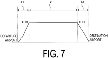
- FIG. 7 is a graph of a time chart relating to the control of the shock wave suppression device according to the first embodiment.
- the aircraft 1 performs takeoff and climb flight operation in a predetermined time period T1 from the aircraft 1 takes off from a departure airport until the aircraft 1 reaches a predetermined cruising altitude, which is Top of Climb (TOC), after taking off. Then, the aircraft 1 performs a cruising operation for cruising at a predetermined cruising altitude in a predetermined time period T2. When reaching a predetermined cruising altitude, which is Top of Descent (TOD), the aircraft 1 performs landing and descending operation and lands on a destination airport in a predetermined time period T3.
- TOC Top of Climb
- the control unit 16 controls the displacing unit 14 in the time period T2 during which the cruising operation is performed. As described above, when the calculated lift coefficient is within the setting range, the control unit 16 sets the bump cover 13 in the deformed state and, in the case of outside of the setting range, sets the bump cover 13 in the steady state. Note that the control of the displacing unit 14 is not particularly limited to the control described above. During the time period T2 during which the cruising operation is performed, the bump cover 13 may be always set in the deformed state, and in the time periods T1 and T3, the bump cover 13 may be set in the steady state. In the first embodiment, the control of the displacing unit 14 is performed automatically, but may be performed manually.
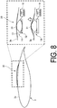
- FIG. 8 is a cross-sectional view schematically illustrating an example of the shock wave suppression device according to the second embodiment.
- the displacing unit 14 has a different configuration from that of the first embodiment. Specifically, the displacing unit 14 includes a contact member 31, a push-up member 32, and a heat source 19.
- the contact member 31 is provided in contact with a surface on the inside of the bump cover 13.
- the contact member 31 has a curved shape in which an upper surface facing the bump cover 13 is convex to the bump cover 13 side from the leading edge side toward the trailing edge side, and deforms the bump cover 13 into a shape in the deformed state.
- the contact member 31 is formed using, for example, a titanium alloy, a stainless steel or an aluminum alloy.
- the push-up member 32 has a configuration to include a shape memory material configured to deform by being heated.
- the push-up member 32 deforms, by being heated, so as to push up the contact member 31 toward the bump cover 13, so that the bump cover 13 is in a deformed state.
- the push-up member 32 pushes up the contact member 31 to deform the bump cover 13 to follow the upper face of the contact member 31.
- the push-up member 32 transforms to a shape before deformation, by being cooled, so as to retract the contact member 31 from the bump cover 13, so that the bump cover 13 is allowed to return to the steady state.
- FIG. 9 is a cross-sectional view schematically illustrating an example of a shock wave suppression device according to the third embodiment.
- the displacing unit 14 has a different configuration from that of the first embodiment. Specifically, the displacing unit 14 includes a pressurizing chamber 41 and a pressurizing source 42.
- the pressurizing chamber 41 is provided in contact with the inside of the bump cover 13.
- the bump cover 13 constitutes a part of the pressurizing chamber 41.
- a pressurizing source 42 is connected to the pressurizing chamber 41 via piping.
- the pressurizing source 42 is a pressurizing fluid extracted from the gas turbine engine 5.
- the pressurizing source 42 is the same as the heat source 19 of the first embodiment, and is a pressurizing fluid supplied to the pressurizing chamber 41 via the air extraction line 21, which is connected to the pressurizing chamber 41.
- the shock wave suppression device 40 pressurizes the interior of the pressurizing chamber 41 by opening the on-off valve 22 to cause the pressurizing fluid to flow into the pressurizing chamber 41.
- the shock wave suppression device 40 decreases the pressure of interior of the pressurizing chamber 41 by closing the on-off valve 22 to cause the pressurizing fluid to flow out of an opening (not illustrated) of the pressurizing chamber 41, so that the bump cover 13 transforms from the deformed state to the steady state by the restoring force of the bump cover 13.
- shock wave suppression devices 10, 30, 40 and the aircraft 1 according to the first to third embodiments are grasped as follows, for example.
- the shock wave suppression devices 10, 30, and 40 are configured to suppress the shock wave generated on the blade surface of the blade (upper blade surface 3a), the shock wave suppression devices including the bump cover 13 provided to follow the blade surface and deformable to protrude outward from the blade surface, and the displacing unit 14 configured to displace the bump cover 13 between the steady state to follow the blade surface and the deformed state to protrude outward from the blade surface.
- the displacing unit 14 can cause the bump cover 13 to transform between the steady state and the deformed state.
- the drag to the blade drag coefficient CD
- the shock wave is generated, an increase in drag due to the shock wave generated on the blade surface can be suppressed by setting the bump cover 13 in the deformed state.
- the bump cover has a curved shape in the deformed state configured to be a continuous surface from the upstream side to the downstream side in the flow direction of the fluid flowing through the blade surface.
- the bump cover 13 can be made to have a shape suitable for suppressing the shock wave.
- the bump cover 13 is the plate material using the elastic alloy.
- the bump cover 13 can be formed using the elastic alloy, the bump cover 13 can be suitably changed from the steady state to the deformed state even in a case where the drag force due to the fluid flowing through the blade surface is large. Additionally, since the bump cover 13 can be transformed from the deformed state to the steady state by the restoring force of the bump cover 13, the configuration can be made simple.
- a portion on the upstream side in the flow direction of the fluid flowing through the blade surface is fixed to the blade surface, and a portion on the downstream side is slidably connected to the blade surface.
- the bump cover 13 since the portion on the downstream side of the bump cover 13 can be slidable, the bump cover 13 can be suitably allowed to be deformed.
- the displacing unit 14 includes the push-up member 18 including the shape memory material configured to deform the bump cover 13 by being heated and the heat source 19 configured to heat the push-up member 18.
- the bump cover 13 can be deformed from the steady state to the deformed state with the simple configuration in which the push-up member 18 is heated by the heat source 19.
- the push-up member 18 has a coil shape after deformation deformed by being heated with the heat source 19.
- the bump cover 13 can be suitably deformed by expanding the push-up member 18.
- the push-up member 18 has a spiral shape after deformation deformed by being heated with the heat source.
- the bump cover 13 can be suitably deformed by expanding the push-up member 18.
- the push-up member 18 has a shape after deformation deformed by being heated with the heat source 19, the shape being configured to follow a surface on the inside of the protruding bump cover 13.
- the bump cover 13 can be suitably deformed by deforming the push-up member 18.
- the displacing unit 14 includes the contact member 31 configured to be in contact with the inside of the bump cover 13, the push-up member 32 including the shape memory alloy configured to deform by being heated to move the contact member 31 toward the bump cover 13, and the heat source 19 configured to heat the push-up member 32.
- the bump cover 13 can be accurately deformed to follow the contact member 31 by heating the push-up member 32 with the heat source 19.
- the heat source 19 is a heating fluid extracted from an engine (gas turbine engine 5) provided to the aircraft 1.
- the configuration since the heating fluid extracted from the engine can be used, the configuration can be simplified without providing a new heat source.
- the displacing unit 14 includes the pressurizing chamber 41 provided in contact with the bump cover 13, and the pressurizing source 42 configured to deform the bump cover 13 by pressurizing the inside of the pressurizing chamber 41.
- the bump cover 13 can be deformed with the simple configuration by pressurizing the inside of the pressurizing chamber 41 with the pressurizing source 42.
- the pressurizing source 42 is a pressurizing fluid extracted from the engine (gas turbine engine 5) provided to the aircraft 1.
- the configuration since the pressurizing fluid extracted from the engine can be used, the configuration can be simplified without providing a new pressure source.
- each of the shock wave suppression devices further includes the control unit 16 configured to control the displacing unit 14, the control unit 16 calculating a lift coefficient on the basis of information on the aircraft 1, and when the calculated lift coefficient is within the preset setting range of the lift coefficient, the control unit 16 controlling the displacing unit 14 to cause the bump cover 13 to be deformed to protrude outward from the blade surface, while in the case of outside of the setting range, the control unit 16 controlling the displacing unit 14 to cause the bump cover 13 to follow the blade surface.
- a drag increase to the blade due to the shock wave can be suppressed by setting the bump cover 13 in the deformed state, and when the lift coefficient is outside of the setting range of the lift coefficient, the drag to the blade can be reduced by setting the bump cover 13 in the steady state.
- An aircraft 1 according to a fourteenth aspect includes the fuselage 2, the blade body (main wing 3) provided to the fuselage 2, and above-described shock wave suppression devices 10, 30, and 40 provided to the blade surface of the blade body.
- the aircraft 1 since the drag on the blade surface can be suitably reduced, the aircraft 1 can be made improved fuel economy efficiency.
Landscapes
- Engineering & Computer Science (AREA)
- Aviation & Aerospace Engineering (AREA)
- Mechanical Engineering (AREA)
- Turbine Rotor Nozzle Sealing (AREA)
- Vibration Dampers (AREA)
- Toys (AREA)
Abstract
Problem
A shock wave suppression device (10) and an aircraft (1) capable of suitably reducing drag on a blade surface are provided.
Solving Means
A shock wave suppression device (10) is configured to suppress a shock wave generated on a blade surface (3a) of a blade (3), the shock wave suppression device including a bump cover (13) provided to follow the blade surface and deformable to protrude outward from the blade surface, and a displacing unit (14) configured to displace the bump cover between a steady state to follow the blade surface and a deformed state to protrude outward from the blade surface. The bump cover has a curved shape in the deformed state configured to be a continuous surface from an upstream side to a downstream side in a flow direction of a fluid flowing through the blade surface.
Description
- The present disclosure relates to a shock wave suppression device and an aircraft.
- A shock bump for inducing a smeared shock foot with a lambda waveform pattern for a shock generated on a surface of an aerodynamic structure are known conventionally (for example, see Patent Document 1). The shock bump is provided to protrude from a surface of a blade, which is the surface of the aerodynamic structure.
- Patent Document 1:
JP 2011-513116 T - The shock bump according to Patent Document 1 induces the smeared shock foot with a lambda waveform pattern, so that a drag increase (an increase in the drag coefficient CD) on a blade surface due to the generation of a shock wave is suppressed. However, the drag reduction by the shock bump exerts an effect within a range of a predetermined lift coefficient CL. That is, the shock bump causes a drag increase on the blade surface outside the range of the predetermined lift coefficient CL.
- Thus, an object of the present disclosure is to provide a shock wave suppression device and an aircraft capable of suitably reducing the drag on the blade surface.
- The shock wave suppression device according to the present disclosure is a shock wave suppression device for suppressing a shock wave generated on a blade surface of a blade, the shock wave suppression device including: a bump cover provided to follow the blade surface and being deformable to protrude outward from the blade surface; and a displacing unit configured to displace the bump cover between a steady state to follow the blade surface and a deformed state to protrude outward from the blade surface.
- The aircraft of the present disclosure includes a fuselage, a blade body provided to the fuselage, and the above-described shock wave suppression device provided to the blade surface of the blade body.
- According to the present disclosure, the drag on the blade surface can be suitably reduced.
-
-
FIG. 1 is a schematic view of an aircraft provided with a shock wave suppression device according to a first embodiment. -
FIG. 2 is a perspective view of the shock wave suppression device according to the first embodiment. -
FIG. 3 is a cross-sectional view schematically illustrating an example of the shock wave suppression device according to the first embodiment. -
FIG. 4 is a cross-sectional view schematically illustrating an example of the shock wave suppression device according to the first embodiment. -
FIG. 5 is a cross-sectional view schematically illustrating an example of the shock wave suppression device according to the first embodiment. -
FIG. 6 is an explanatory view illustrating a transformation of states of the shock wave suppression device according to the first embodiment. -
FIG. 7 is a graph of a time chart relating to control of the shock wave suppression device according to the first embodiment. -
FIG. 8 is a cross-sectional view schematically illustrating an example of a shock wave suppression device according to a second embodiment. -
FIG. 9 is a cross-sectional view schematically illustrating an example of a shock wave suppression device according to a third embodiment. - Detailed descriptions will be given below of embodiments according to the present disclosure on the basis of the drawings. Note that, the invention is not limited to the embodiments. Further, the constituent elements in the following embodiments include those that can be easily replaced by a person skilled in the art or those that are substantially the same. Further, the constituent elements described below can be combined as appropriate, and in case of a plurality of embodiments, the embodiments can be combined with one another.
- A shock
wave suppression device 10 according to the first embodiment is provided, for example, on amain wing 3 of an aircraft 1, and is provided to a blade surface of themain wing 3, in particular, on an upper blade surface that is the low pressure side. First, with reference toFIG. 1 , description is made of the aircraft 1. -
FIG. 1 is a schematic view of an aircraft provided with the shock wave suppression device according to the first embodiment. The aircraft 1 includes afuselage 2, amain wing 3, a horizontal tail and vertical tail (not illustrated), agas turbine engine 5, and the shockwave suppression device 10. - The
fuselage 2 is provided to extend along the roll axis direction connecting a nose and a tail. Thefuselage 2 is formed in a cylindrical shape having the roll axis as a center. Themain wing 3 includes blades provided to protrude to both outsides at a center of the roll axis direction of thefuselage 2 in a pitch axis direction orthogonal to the roll axis direction. The horizontal tail and the vertical tail are provided on the tail side of thefuselage 2. Thegas turbine engine 5 is provided on the lower surface side of themain wing 3. As will be described in detail below, in thegas turbine engine 5, an extracted heating fluid serves as a heat source of the shockwave suppression device 10. Note that the heating fluid may be compressed air compressed in a compressor provided to thegas turbine engine 5, or may be an exhaust gas exhausted from a turbine provided to thegas turbine engine 5. - Next, the shock
wave suppression device 10 will be described with reference toFIGS. 1 to 6 .FIG. 2 is a perspective view of a shock wave suppression device according to the first embodiment.FIGS. 3 to 5 are cross-sectional views schematically illustrating examples of shock wave suppression devices according to the first embodiment.FIG. 6 is an explanatory view illustrating a transformation of states of a shock wave suppression device according to the first embodiment. - As illustrated in
FIG. 2 , the shockwave suppression device 10 is provided to theupper blade surface 3a that is the low pressure side of themain wing 3. A plurality of the shockwave suppression devices 10 is provided side-by-side at a predetermined interval in a blade longitudinal direction connecting a base end and a leading end of themain wing 3. - As illustrated in
FIG. 3 , the shockwave suppression device 10 includes abump cover 13 provided to follow theupper blade surface 3a, and adisplacing unit 14 configured to displace the state of thebump cover 13. Further, the shockwave suppression device 10 includes atemperature pressure sensor 15 and acontrol unit 16. - The
bump cover 13 is a plate material using an elastic alloy. The elastic alloy is a metal configured to deform by an elastic strain amount of 1% or greater without phase transformation, and includes a superelastic alloy. Thebump cover 13 is provided from the leading edge side to the trailing edge side of themain wing 3. Here, the upstream side in the flow direction of a fluid passing through themain wing 3 is the leading edge side and the downstream side is the trailing edge side. The direction connecting the leading edge side and the trailing edge side is the blade width direction. Thebump cover 13 is a plate capable of elastically deforming within a range of from 10% to 60% with respect to a length in the blade width direction. - As illustrated in
FIG. 6 , thebump cover 13 has a shape in a state before deformation, that is, in a steady state, the shape being configured to follow theupper blade surface 3a. On the other hand, thebump cover 13 has a shape in a state after deformation, that is, in a deformed state, the shape being configured to protrude to the outside of theupper blade surface 3a. Specifically, thebump cover 13 has a curved shape in the deformed state configured to be a continuous surface from the leading edge side to the trailing edge side. Here, since thebump cover 13 is elastically deformed in the deformed state, it has a restoring force for returning to the steady state. - As illustrated in
FIG. 6 , in thebump cover 13, the leading edge side is fixed to theupper blade surface 3a, and the trailing edge side is connected to theupper blade surface 3a via asliding mechanism unit 17. The slidingmechanism unit 17 is, for example, a linear slider provided to extend with the blade width direction being a moving direction. The slidingmechanism unit 17 allows thebump cover 13 to be deformed by the trailing edge side of thebump cover 13 moving to follow the deformation of thebump cover 13. - On both sides in the blade longitudinal direction of the
bump cover 13,occlusion members 20 are provided to occlude a gap between thebump cover 13 in the deformed state and theupper blade surface 3a. Theocclusion member 20 may be configured to follow the deformation of thebump cover 13, and is, for example, a rubber packing, a rubber sheet, a shape memory film, and a deformable metal shield. - As illustrated in
FIGS. 3 to 5 , the displacingunit 14 displaces thebump cover 13 between the steady state and the deformed state. The displacingunit 14 includes a push-upmember 18 configured to deform thebump cover 13, and aheat source 19 configured to heat the push-upmember 18. - The push-up
member 18 has a configuration to include a shape memory material configured to deform by being heated. The shape memory material is, for example, a shape memory alloy or a shape memory polymer. The push-upmember 18 deforms toward the outside of theupper blade surface 3a by being heated, so that thebump cover 13 becomes in the deformed state. On the other hand, the push-upmember 18 transforms to a shape before the deformation by being cooled to allow thebump cover 13 to be the steady state. - The
heat source 19 heats the push-upmember 18, and as described above, the heating fluid extracted from thegas turbine engine 5 is used. Specifically, as illustrated inFIG. 1 , theheat source 19 includes anair extraction line 21 connected to thegas turbine engine 5, and an on-offvalve 22 provided to theair extraction line 21. The heating fluid extracted from thegas turbine engine 5 flows through theair extraction line 21. The on-offvalve 22 in the valve-on state allows for the flow of the heating fluid from theair extraction line 21 to the push-upmember 18, so that the push-upmember 18 is heated. On the other hand, the on-offvalve 22 in the valve-off state restricts the flow of the heating fluid from theair extraction line 21 to the push-upmember 18, so that the heating to the push-upmember 18 is stopped. Note that theheat source 19 is not particularly limited to the above, and for example, a heating device such as a heater may be applied. - Examples of the push-up
member 18 will now be described with reference toFIGS. 3 to 5 . A push-upmember 18a illustrated inFIG. 3 has a coil shape after deformation deformed by being heated with theheat source 19. Furthermore, the push-upmember 18a is in an unjoined state with respect to thebump cover 13. - A push-up
member 18b illustrated inFIG. 4 has a spiral shape after deformation deformed by being heated with theheat source 19. The push-upmember 18b is formed in the spiral shape, for example, by winding a plate-shaped member of the shape memory alloy. Similar to the push-upmember 18a, the push-upmember 18b is in an unjoined state with respect to thebump cover 13. - A push-up
member 18c illustrated inFIG. 5 has a shape after deformation deformed by being heated with theheat source 19, the shape being configured to follow a surface on the inside of the protrudingbump cover 13. The push-upmember 18c has a plate shape configured to be joined to the surface on the inside of thebump cover 13. - As illustrated in
FIG. 1 , thetemperature pressure sensor 15 is a sensor configured to detect the temperature and the pressure of the heating fluid flowing through theair extraction line 21. Thetemperature pressure sensor 15 may include a temperature sensor and a pressure sensor that are integrated or separated. Thetemperature pressure sensor 15 is connected to thecontrol unit 16, and outputs information regarding the temperature and the pressure to thecontrol unit 16. - The
control unit 16 includes an integrated circuit such as a Central Processing Unit (CPU). Thecontrol unit 16 is connected to the displacingunit 14 and thetemperature pressure sensor 15. Thecontrol unit 16 acquires information on the aircraft 1, and the information on the aircraft 1 includes, for example, a fuselage weight based on the remaining amount of fuel in the aircraft 1, a navigation speed (Mach number) of the aircraft 1, an attack angle of the aircraft 1, and a fuselage altitude of the aircraft 1. - The
control unit 16 calculates a lift coefficient (CL) on the basis of the information on the aircraft 1. Thecontrol unit 16 performs the control of the displacingunit 14 on the basis of the calculated lift coefficient and the detection result of thetemperature pressure sensor 15. Note that when performing the control of the displacingunit 14, thecontrol unit 16 sets a preset setting range of the lift coefficient. The setting range is obtained in advance by analysis, experimentation, or the like, and is a range of the lift coefficient in which the shock wave is generated. Then, thecontrol unit 16 performs the control of the displacingunit 14 on the basis of the preset setting range of the lift coefficient and the calculated lift coefficient CL. - When the calculated lift coefficient CL is within the preset setting range of the lift coefficient, the
control unit 16 controls the displacingunit 14 to cause thebump cover 13 to be deformed to protrude outward from theupper blade surface 3a, while in the case of outside of the setting range, controls the displacingunit 14 to cause thebump cover 13 to follow theupper blade surface 3a. In other words, when the calculated lift coefficient is within the preset setting range of the lift coefficient, thecontrol unit 16 opens the on-offvalve 22 to heat and deform the push-upmember 18 with the heating fluid to cause thebump cover 13 to be in the deformed state. At this time, thecontrol unit 16 calculates, based on the temperature detected by thetemperature pressure sensor 15, a supply amount of the heating fluid so as to correspond to the amount of heat required for deforming the push-upmember 18, and controls the on-offvalve 22 so as to be a degree of opening corresponding to the calculated supply amount. - On the other hand, when the calculated lift coefficient is outside of the preset setting range of the lift coefficient, the
control unit 16 closes the on-offvalve 22 to stop heating the push-upmember 18 with the heating fluid, causes the push-upmember 18 to transform to the state before deformation, and causes thebump cover 13 to transform to the steady state by the restoring force of thebump cover 13. - Next, with reference to
FIG. 7 , the control of the displacingunit 14 by thecontrol unit 16 will be described.FIG. 7 is a graph of a time chart relating to the control of the shock wave suppression device according to the first embodiment. The aircraft 1 performs takeoff and climb flight operation in a predetermined time period T1 from the aircraft 1 takes off from a departure airport until the aircraft 1 reaches a predetermined cruising altitude, which is Top of Climb (TOC), after taking off. Then, the aircraft 1 performs a cruising operation for cruising at a predetermined cruising altitude in a predetermined time period T2. When reaching a predetermined cruising altitude, which is Top of Descent (TOD), the aircraft 1 performs landing and descending operation and lands on a destination airport in a predetermined time period T3. - The
control unit 16 controls the displacingunit 14 in the time period T2 during which the cruising operation is performed. As described above, when the calculated lift coefficient is within the setting range, thecontrol unit 16 sets thebump cover 13 in the deformed state and, in the case of outside of the setting range, sets thebump cover 13 in the steady state. Note that the control of the displacingunit 14 is not particularly limited to the control described above. During the time period T2 during which the cruising operation is performed, thebump cover 13 may be always set in the deformed state, and in the time periods T1 and T3, thebump cover 13 may be set in the steady state. In the first embodiment, the control of the displacingunit 14 is performed automatically, but may be performed manually. - Next, with reference to
FIG. 8 , a shockwave suppression device 30 according to the second embodiment is described. In the second embodiment, in order to avoid redundant descriptions, descriptions will be given only for structural elements different from those of the first embodiment, and the same reference numerals will be assigned to structural elements having the same configuration as that of the first embodiment.FIG. 8 is a cross-sectional view schematically illustrating an example of the shock wave suppression device according to the second embodiment. - As illustrated in
FIG. 8 , in the shockwave suppression device 30 according to the second embodiment, the displacingunit 14 has a different configuration from that of the first embodiment. Specifically, the displacingunit 14 includes acontact member 31, a push-upmember 32, and aheat source 19. - The
contact member 31 is provided in contact with a surface on the inside of thebump cover 13. Thecontact member 31 has a curved shape in which an upper surface facing thebump cover 13 is convex to thebump cover 13 side from the leading edge side toward the trailing edge side, and deforms thebump cover 13 into a shape in the deformed state. Thecontact member 31 is formed using, for example, a titanium alloy, a stainless steel or an aluminum alloy. - Similar to the push-up
member 18 of the first embodiment, the push-upmember 32 has a configuration to include a shape memory material configured to deform by being heated. the push-upmember 32 deforms, by being heated, so as to push up thecontact member 31 toward thebump cover 13, so that thebump cover 13 is in a deformed state. The push-upmember 32 pushes up thecontact member 31 to deform thebump cover 13 to follow the upper face of thecontact member 31. On the other hand, the push-upmember 32 transforms to a shape before deformation, by being cooled, so as to retract thecontact member 31 from thebump cover 13, so that thebump cover 13 is allowed to return to the steady state. - Next, with reference to
FIG. 9 , a shockwave suppression device 40 according to a third embodiment is described. In the third embodiment, in order to avoid redundant descriptions, descriptions will be given only for structural elements different from those of the first and second embodiments, and the same reference numerals will be assigned to structural elements having the same configuration as that of the first embodiment.FIG. 9 is a cross-sectional view schematically illustrating an example of a shock wave suppression device according to the third embodiment. - As illustrated in
FIG. 9 , in the shockwave suppression device 40 according to the third embodiment, the displacingunit 14 has a different configuration from that of the first embodiment. Specifically, the displacingunit 14 includes a pressurizingchamber 41 and a pressurizingsource 42. - The pressurizing
chamber 41 is provided in contact with the inside of thebump cover 13. In other words, thebump cover 13 constitutes a part of the pressurizingchamber 41. A pressurizingsource 42 is connected to the pressurizingchamber 41 via piping. The pressurizingsource 42 is a pressurizing fluid extracted from thegas turbine engine 5. In other words, the pressurizingsource 42 is the same as theheat source 19 of the first embodiment, and is a pressurizing fluid supplied to the pressurizingchamber 41 via theair extraction line 21, which is connected to the pressurizingchamber 41. - The shock
wave suppression device 40 pressurizes the interior of the pressurizingchamber 41 by opening the on-offvalve 22 to cause the pressurizing fluid to flow into the pressurizingchamber 41. When the pressure inside the pressurizingchamber 41 increases, thebump cover 13 deforms from the steady state to the deformed state by the pressure. On the other hand, the shockwave suppression device 40 decreases the pressure of interior of the pressurizingchamber 41 by closing the on-offvalve 22 to cause the pressurizing fluid to flow out of an opening (not illustrated) of the pressurizingchamber 41, so that thebump cover 13 transforms from the deformed state to the steady state by the restoring force of thebump cover 13. - Note that when the
bump cover 13 is deformed, the trailing edge side of thebump cover 13 slides by the slidingmechanism unit 17, and thus a sealing function may be added to the slidingmechanism unit 17 so that the pressurizing fluid does not leak from the pressurizingchamber 41 via the slidingmechanism unit 17. - As described above, the shock
wave suppression devices - The shock
wave suppression devices upper blade surface 3a), the shock wave suppression devices including thebump cover 13 provided to follow the blade surface and deformable to protrude outward from the blade surface, and the displacingunit 14 configured to displace thebump cover 13 between the steady state to follow the blade surface and the deformed state to protrude outward from the blade surface. - According to the configuration, the displacing
unit 14 can cause thebump cover 13 to transform between the steady state and the deformed state. Thus, when the shock wave is not generated, the drag to the blade (drag coefficient CD) can be reduced by setting thebump cover 13 in the steady state. On the other hand, when the shock wave is generated, an increase in drag due to the shock wave generated on the blade surface can be suppressed by setting thebump cover 13 in the deformed state. - As a second aspect, the bump cover has a curved shape in the deformed state configured to be a continuous surface from the upstream side to the downstream side in the flow direction of the fluid flowing through the blade surface.
- According to the configuration, the
bump cover 13 can be made to have a shape suitable for suppressing the shock wave. - As a third aspect, the
bump cover 13 is the plate material using the elastic alloy. - According to the configuration, since the
bump cover 13 can be formed using the elastic alloy, thebump cover 13 can be suitably changed from the steady state to the deformed state even in a case where the drag force due to the fluid flowing through the blade surface is large. Additionally, since thebump cover 13 can be transformed from the deformed state to the steady state by the restoring force of thebump cover 13, the configuration can be made simple. - As a fourth aspect, in the bump cover, a portion on the upstream side in the flow direction of the fluid flowing through the blade surface is fixed to the blade surface, and a portion on the downstream side is slidably connected to the blade surface.
- According to the configuration, since the portion on the downstream side of the
bump cover 13 can be slidable, thebump cover 13 can be suitably allowed to be deformed. - As a fifth aspect, the displacing
unit 14 includes the push-upmember 18 including the shape memory material configured to deform thebump cover 13 by being heated and theheat source 19 configured to heat the push-upmember 18. - According to the configuration, the
bump cover 13 can be deformed from the steady state to the deformed state with the simple configuration in which the push-upmember 18 is heated by theheat source 19. - As a sixth aspect, the push-up
member 18 has a coil shape after deformation deformed by being heated with theheat source 19. - According to the configuration, the
bump cover 13 can be suitably deformed by expanding the push-upmember 18. - As a seventh aspect, the push-up
member 18 has a spiral shape after deformation deformed by being heated with the heat source. - According to the configuration, the
bump cover 13 can be suitably deformed by expanding the push-upmember 18. - As an eighth aspect, the push-up
member 18 has a shape after deformation deformed by being heated with theheat source 19, the shape being configured to follow a surface on the inside of the protrudingbump cover 13. - According to the configuration, the
bump cover 13 can be suitably deformed by deforming the push-upmember 18. - As a ninth aspect, the displacing
unit 14 includes thecontact member 31 configured to be in contact with the inside of thebump cover 13, the push-upmember 32 including the shape memory alloy configured to deform by being heated to move thecontact member 31 toward thebump cover 13, and theheat source 19 configured to heat the push-upmember 32. - According to the configuration, the
bump cover 13 can be accurately deformed to follow thecontact member 31 by heating the push-upmember 32 with theheat source 19. - As a tenth aspect, the
heat source 19 is a heating fluid extracted from an engine (gas turbine engine 5) provided to the aircraft 1. - According to the configuration, since the heating fluid extracted from the engine can be used, the configuration can be simplified without providing a new heat source.
- As an eleventh aspect, the displacing
unit 14 includes the pressurizingchamber 41 provided in contact with thebump cover 13, and the pressurizingsource 42 configured to deform thebump cover 13 by pressurizing the inside of the pressurizingchamber 41. - According to the configuration, the
bump cover 13 can be deformed with the simple configuration by pressurizing the inside of the pressurizingchamber 41 with the pressurizingsource 42. - As a twelfth aspect, the pressurizing
source 42 is a pressurizing fluid extracted from the engine (gas turbine engine 5) provided to the aircraft 1. - According to the configuration, since the pressurizing fluid extracted from the engine can be used, the configuration can be simplified without providing a new pressure source.
- As a thirteenth aspect, each of the shock wave suppression devices further includes the
control unit 16 configured to control the displacingunit 14, thecontrol unit 16 calculating a lift coefficient on the basis of information on the aircraft 1, and when the calculated lift coefficient is within the preset setting range of the lift coefficient, thecontrol unit 16 controlling the displacingunit 14 to cause thebump cover 13 to be deformed to protrude outward from the blade surface, while in the case of outside of the setting range, thecontrol unit 16 controlling the displacingunit 14 to cause thebump cover 13 to follow the blade surface. - According to the configuration, when the lift coefficient is within the setting range, a drag increase to the blade due to the shock wave can be suppressed by setting the
bump cover 13 in the deformed state, and when the lift coefficient is outside of the setting range of the lift coefficient, the drag to the blade can be reduced by setting thebump cover 13 in the steady state. - An aircraft 1 according to a fourteenth aspect includes the
fuselage 2, the blade body (main wing 3) provided to thefuselage 2, and above-described shockwave suppression devices - According to the configuration, since the drag on the blade surface can be suitably reduced, the aircraft 1 can be made improved fuel economy efficiency.
-
- 1 Aircraft
- 2 Fuselage
- 3 Main wing
- 3a Upper blade surface
- 5 Gas turbine engine
- 10, 30, 40 Shock wave suppression device
- 13 Bump cover
- 14 Displacing unit
- 15 Temperature pressure sensor
- 16 Control unit
- 17 Sliding mechanism unit
- 18, 32 Push-up member
- 19 Heat source
- 20 Occlusion member
- 21 Air extraction line
- 22 On-off valve
- 31 Contact member
- 41 Pressurizing chamber
- 42 Pressurizing source
Claims (14)
- A shock wave suppression device for suppressing a shock wave generated on a blade surface of a blade, the shock wave suppression device comprising:a bump cover provided to follow the blade surface and being deformable to protrude outward from the blade surface; anda displacing unit configured to displace the bump cover between a steady state to follow the blade surface and a deformed state to protrude outward from the blade surface.
- The shock wave suppression device according to claim 1,
wherein the bump cover has a curved shape in the deformed state configured to be a continuous surface from an upstream side to a downstream side in a flow direction of a fluid flowing through the blade surface. - The shock wave suppression device according to claim 1 or 2,
wherein the bump cover is a plate material using an elastic alloy. - The shock wave suppression device according to any one of claims 1 to 3,
wherein, in the bump cover, a portion on an upstream side in a flow direction of a fluid flowing through the blade surface is fixed to the blade surface, and a portion on a downstream side is slidably connected to the blade surface. - The shock wave suppression device according to any one of claims 1 to 4, wherein the displacing unit includes:a push-up member including a shape memory material configured to deform the bump cover by being heated, anda heat source configured to heat the push-up member.
- The shock wave suppression device according to claim 5,
wherein the push-up member has a coil shape after deformation deformed by being heated with the heat source. - The shock wave suppression device according to claim 5,
wherein the push-up member has a spiral shape after deformation deformed by being heated with the heat source. - The shock wave suppression device according to claim 5,
wherein the push-up member has a shape after deformation deformed by being heated with the heat source, the shape being configured to follow a surface on the inside of the protruding bump cover. - The shock wave suppression device according to any one of claims 1 to 4, wherein the displacing unit includes:a contact member configured to be in contact with the inside of the bump cover,a push-up member including a shape memory alloy configured to deform by being heated to move the contact member toward the bump cover, anda heat source configured to heat the push-up member.
- The shock wave suppression device according to any one of claims 5 to 9,
wherein the heat source is a heating fluid extracted from an engine provided to an aircraft. - The shock wave suppression device according to any one of claims 1 to 4,
wherein the displacing unit includes:a pressurizing chamber provided in contact with the bump cover, anda pressurizing source configured to deform the bump cover by pressurizing the inside of the pressurizing chamber. - The shock wave suppression device according to claim 11,
wherein the pressurizing source is a pressurizing fluid extracted from an engine provided to an aircraft. - The shock wave suppression device according to any one of claims 1 to 12, further comprising:a control unit configured to control the displacing unit,wherein the control unit calculating a lift coefficient on the basis of information on the aircraft, and when the calculated lift coefficient is within the preset setting range of the lift coefficient, controlling the displacing unit to cause the bump cover to be deformed to protrude outward from the blade surface, while in the case of outside of the setting range, controlling the displacing unit to cause the bump cover to follow the blade surface.
- An aircraft comprising:a fuselage;a blade body provided to the fuselage; andthe shock wave suppression device according to any one of claims 1 to 13 provided to the blade surface of the blade body.
Applications Claiming Priority (1)
| Application Number | Priority Date | Filing Date | Title |
|---|---|---|---|
| JP2020026257A JP2021130375A (en) | 2020-02-19 | 2020-02-19 | Shock wave suppression device and aircraft |
Publications (1)
| Publication Number | Publication Date |
|---|---|
| EP3868650A1 true EP3868650A1 (en) | 2021-08-25 |
Family
ID=74215833
Family Applications (1)
| Application Number | Title | Priority Date | Filing Date |
|---|---|---|---|
| EP21153194.2A Withdrawn EP3868650A1 (en) | 2020-02-19 | 2021-01-25 | Shock wave suppression device and aircraft |
Country Status (4)
| Country | Link |
|---|---|
| US (1) | US11530029B2 (en) |
| EP (1) | EP3868650A1 (en) |
| JP (1) | JP2021130375A (en) |
| CN (1) | CN113277072A (en) |
Families Citing this family (3)
| Publication number | Priority date | Publication date | Assignee | Title |
|---|---|---|---|---|
| EP4054933B1 (en) * | 2019-11-06 | 2024-06-26 | Airbus Operations GmbH | Flow body for an aircraft with a selectively activatable shock bump |
| DE102019130596B4 (en) * | 2019-11-13 | 2022-10-27 | Deutsches Zentrum für Luft- und Raumfahrt e.V. | Method for suppressing aeroelastic instabilities on transonic aircraft and aircraft with devices for carrying out the method by direct intervention in the aerodynamic boundary layer |
| DE102022115072B4 (en) | 2022-06-15 | 2024-10-17 | Deutsches Zentrum für Luft- und Raumfahrt e.V. | Transonic wing for a flying object |
Citations (6)
| Publication number | Priority date | Publication date | Assignee | Title |
|---|---|---|---|---|
| US3158338A (en) * | 1963-02-18 | 1964-11-24 | Walton W Cushman | Sustaining airfoils having variable configurations to vary lift characteristics |
| US5433404A (en) * | 1991-08-01 | 1995-07-18 | The Secretary Of State For Defence In Her Britannic Majesty's Government Of The United Kingdom Of Great Britain And Northern Ireland | Airfoil with variable geometry expansion surface |
| GB2296696A (en) * | 1994-12-23 | 1996-07-10 | Deutsche Forsch Luft Raumfahrt | Deformable aerofoil |
| US20110042524A1 (en) * | 2008-02-21 | 2011-02-24 | Cornerstone Research Group | Passive adaptive structures |
| JP2011513116A (en) | 2008-02-29 | 2011-04-28 | エアバス・ユ―ケ―・リミテッド | Aerodynamic structure with unevenly spaced shock bumps |
| EP2562080A1 (en) * | 2011-08-16 | 2013-02-27 | The Boeing Company | Variable camber fluid-dynamic body utilizing optimized smart materials |
Family Cites Families (1)
| Publication number | Priority date | Publication date | Assignee | Title |
|---|---|---|---|---|
| GB0803730D0 (en) | 2008-02-29 | 2008-04-09 | Airbus Uk Ltd | Shock bump array |
-
2020
- 2020-02-19 JP JP2020026257A patent/JP2021130375A/en not_active Withdrawn
-
2021
- 2021-01-22 US US17/155,491 patent/US11530029B2/en active Active
- 2021-01-25 EP EP21153194.2A patent/EP3868650A1/en not_active Withdrawn
- 2021-01-28 CN CN202110116922.9A patent/CN113277072A/en not_active Withdrawn
Patent Citations (6)
| Publication number | Priority date | Publication date | Assignee | Title |
|---|---|---|---|---|
| US3158338A (en) * | 1963-02-18 | 1964-11-24 | Walton W Cushman | Sustaining airfoils having variable configurations to vary lift characteristics |
| US5433404A (en) * | 1991-08-01 | 1995-07-18 | The Secretary Of State For Defence In Her Britannic Majesty's Government Of The United Kingdom Of Great Britain And Northern Ireland | Airfoil with variable geometry expansion surface |
| GB2296696A (en) * | 1994-12-23 | 1996-07-10 | Deutsche Forsch Luft Raumfahrt | Deformable aerofoil |
| US20110042524A1 (en) * | 2008-02-21 | 2011-02-24 | Cornerstone Research Group | Passive adaptive structures |
| JP2011513116A (en) | 2008-02-29 | 2011-04-28 | エアバス・ユ―ケ―・リミテッド | Aerodynamic structure with unevenly spaced shock bumps |
| EP2562080A1 (en) * | 2011-08-16 | 2013-02-27 | The Boeing Company | Variable camber fluid-dynamic body utilizing optimized smart materials |
Also Published As
| Publication number | Publication date |
|---|---|
| US20210253226A1 (en) | 2021-08-19 |
| CN113277072A (en) | 2021-08-20 |
| US11530029B2 (en) | 2022-12-20 |
| JP2021130375A (en) | 2021-09-09 |
Similar Documents
| Publication | Publication Date | Title |
|---|---|---|
| EP3868650A1 (en) | Shock wave suppression device and aircraft | |
| CA2114129C (en) | Aerofoil with variable geometry expansion surface | |
| Green | Laminar flow control-back to the future? | |
| Coder | Enhancement of the amplification factor transport transition modeling framework | |
| Genç et al. | Flow over an aerofoil without and with a leading-edge slat at a transitional Reynolds number | |
| Ko et al. | Development of a morphing flap using shape memory alloy actuators: the aerodynamic characteristics of a morphing flap | |
| Johnston et al. | Investigation of a bio-inspired lift-enhancing effector on a 2D airfoil | |
| Hartwich et al. | AFC-enabled simplified high-lift system integration study | |
| Hövelmann et al. | AVT-183 diamond wing flow field characteristics Part 1: Varying leading-edge roughness and the effects on flow separation onset | |
| Currier et al. | Analysis of the onset of dynamic stall | |
| Fricke et al. | Numerical studies of active flow control applied at the engine-wing junction | |
| Kozul et al. | Direct numerical simulation of riblets applied to gas turbine compressor blades at on-and off-design incidences | |
| Ciobaca et al. | Active flow control for an outer wing model of a take-off transport aircraft configuration-a numerical study | |
| Hawkins | YF-16 inlet design and performance | |
| Raghunathan et al. | Computed effects of heat transfer on the transonic flow over an aerofoil | |
| EP3725673B1 (en) | Transonic airfoil, blade, and aircraft | |
| Şahin et al. | Aerodynamic modelling and analysis of a novel mechanism for chord and camber morphing wing | |
| Venkatachari et al. | Pretest computational assessment of boundary layer transition in the NASA juncture flow model with an NACA 0015-based wing | |
| Heine et al. | Aerodynamic scaling of general aviation airfoil for low Reynolds number application | |
| Frink | Numerical analysis of incipient separation on 53-deg swept diamond wing | |
| Ismail et al. | Applying computational fluid dynamic to predict the thermal performance of the nacelle anti-icing system in real flight scenarios | |
| Ciobaca et al. | Wind tunnel experiments with active flow control for an outer wing model | |
| GOLDBERG et al. | Starting criterion for hypersonic inlets | |
| Donovan | Control of shock wave/turbulent boundary layer interactions using tangential injection | |
| Luckring et al. | An Application of CFD to Guide Forced Boundary-Layer Transition at Subsonic and Transonic Speeds for a Lambda-Wing Configuration |
Legal Events
| Date | Code | Title | Description |
|---|---|---|---|
| PUAI | Public reference made under article 153(3) epc to a published international application that has entered the european phase |
Free format text: ORIGINAL CODE: 0009012 |
|
| STAA | Information on the status of an ep patent application or granted ep patent |
Free format text: STATUS: REQUEST FOR EXAMINATION WAS MADE |
|
| 17P | Request for examination filed |
Effective date: 20210125 |
|
| AK | Designated contracting states |
Kind code of ref document: A1 Designated state(s): AL AT BE BG CH CY CZ DE DK EE ES FI FR GB GR HR HU IE IS IT LI LT LU LV MC MK MT NL NO PL PT RO RS SE SI SK SM TR |
|
| STAA | Information on the status of an ep patent application or granted ep patent |
Free format text: STATUS: THE APPLICATION HAS BEEN WITHDRAWN |
|
| 18W | Application withdrawn |
Effective date: 20230427 |