EP3868646A1 - Dispositif de portabilite variable comprenant un diffuseur anti stratification - Google Patents
Dispositif de portabilite variable comprenant un diffuseur anti stratification Download PDFInfo
- Publication number
- EP3868646A1 EP3868646A1 EP21155129.6A EP21155129A EP3868646A1 EP 3868646 A1 EP3868646 A1 EP 3868646A1 EP 21155129 A EP21155129 A EP 21155129A EP 3868646 A1 EP3868646 A1 EP 3868646A1
- Authority
- EP
- European Patent Office
- Prior art keywords
- sheath
- air
- variable
- mixer
- variable portability
- Prior art date
- Legal status (The legal status is an assumption and is not a legal conclusion. Google has not performed a legal analysis and makes no representation as to the accuracy of the status listed.)
- Granted
Links
Images



Classifications
-
- B—PERFORMING OPERATIONS; TRANSPORTING
- B64—AIRCRAFT; AVIATION; COSMONAUTICS
- B64B—LIGHTER-THAN AIR AIRCRAFT
- B64B1/00—Lighter-than-air aircraft
- B64B1/58—Arrangements or construction of gas-bags; Filling arrangements
- B64B1/62—Controlling gas pressure, heating, cooling, or discharging gas
-
- B—PERFORMING OPERATIONS; TRANSPORTING
- B64—AIRCRAFT; AVIATION; COSMONAUTICS
- B64B—LIGHTER-THAN AIR AIRCRAFT
- B64B1/00—Lighter-than-air aircraft
- B64B1/02—Non-rigid airships
-
- B—PERFORMING OPERATIONS; TRANSPORTING
- B64—AIRCRAFT; AVIATION; COSMONAUTICS
- B64B—LIGHTER-THAN AIR AIRCRAFT
- B64B1/00—Lighter-than-air aircraft
- B64B1/58—Arrangements or construction of gas-bags; Filling arrangements
-
- B—PERFORMING OPERATIONS; TRANSPORTING
- B64—AIRCRAFT; AVIATION; COSMONAUTICS
- B64B—LIGHTER-THAN AIR AIRCRAFT
- B64B1/00—Lighter-than-air aircraft
- B64B1/58—Arrangements or construction of gas-bags; Filling arrangements
- B64B1/64—Gas valve operating mechanisms
Definitions
- the present invention relates to the field of variable portability devices using a gas lighter than air to rise in the atmosphere. More specifically, the invention relates to variable portability devices provided with a single reservoir for storing under pressure gas lighter than air such as helium, neon, methane, ethane and hydrogen. .
- a variable portability device can be interpreted as a stratospheric airship platform with a pressurized flexible envelope, known by the Anglo-Saxon name “Blimp”.
- variable portability devices have had several completely sealed balloons containing the lighter-than-air gas. It is these balloons filled with the lighter-than-air gas that provide lift for the variable portability devices. These balloons are included in a flexible structure forming the envelope of the variable portability devices. The rest of the volume of the envelope is occupied by air. To go up, air is ejected and to go down, air is injected. The multiplicity of air balloons guarantees longitudinal static stability regardless of the air filling rate.
- the gas lighter than air being contained in the balloons it is never in direct contact with the air injected into the envelope of the variable portability device.
- a solution of injecting air directly into a single reservoir is not viable.
- the heterogeneous mixture between the gas lighter than air and the air which results from it can induce an instability in attitude of the device of variable portability, that is to say too great an angular difference between the horizontal plane and the longitudinal axis of the stratospheric variable portability device.
- This instability can increase to the point of completely tilting the stratospheric variable portability device to the vertical.
- the gas lighter than air having a density lower than the density of the air the gas lighter than air would naturally be disposed in the upper part of the tank leaving the air in the part. stratospheric variable portability device tank bass.
- the invention aims to overcome all or part of the problems mentioned above by proposing a device of variable portability comprising a mixer capable of ensuring a homogeneous mixture between air and a gas lighter than air within a single hermetic pressure chamber.
- the mixer comprises a sheath provided with at least one perforation and at least one air injector in the sheath.
- the sheath is obtained from a porous fabric.
- variable portability device extends along a first longitudinal axis and the sheath has the shape of a tube extending substantially along the first longitudinal axis of the variable portability device.
- the sheath extends along a second axis intersecting with the first longitudinal axis of the variable portability device.
- At least one injector is placed along the sheath of the mixer along the first longitudinal axis of the variable portability device.
- At least one injector is placed at one end of the sheath of the mixer.
- a section of the sheath of the mixer substantially perpendicular to the first longitudinal axis is defined by a characteristic dimension greater than 15 centimeters.
- the section of the sheath of the mixer substantially perpendicular to the first longitudinal axis is defined by a characteristic dimension less than 250 centimeters.
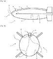
- the figure 1a shows a schematic side view of a sectional view of a variable portability device 1.
- the sectional view of the figure 1a is produced in a vertical plane comprising a longitudinal axis A1 of the variable portability device 1.
- the figure 1b shows a schematic front view of a sectional view of the variable portability device 1.
- the sectional view of the figure 1b is produced in a vertical plane perpendicular to the longitudinal axis A1 of the variable portability device 1.
- the variable portability device 1 comprises a hermetic chamber 4 under pressure intended to accommodate a gas of density less than the density of air . This hermetic enclosure 4 can correspond, from an external point of view to the envelope of the variable portability device 1.
- the hermetic enclosure 4 is therefore in contact, along an external face 41, with an external medium 3, and, along an internal face 42, gas of density less than the density of air.
- the hermetic enclosure 4 provides the seal between the external environment 3 and the gas contained in the hermetic enclosure 4.
- the invention also applies with an additional balloon containing the gas lighter than air which ensures the sealing. In this case, the additional balloon acts as the hermetic enclosure 4.
- the variable portability device 1 also comprises a mixer 6, partially disposed in the hermetic enclosure 4 capable of introducing air inside the hermetic enclosure 4 and of mixing this air with the gas of lower density. the density of the air inside the enclosure hermetic 4.
- the mixer 6 comprises a sheath 61 arranged inside the hermetic enclosure 4 and an injector 62 connected on the one hand to the sheath 61 and on the other hand to the external environment 3. In this way , the injector 62 makes it possible to inject air from the external medium 3 inside the sheath 61.
- the mixer 6 is positioned against an upper part 43 of the internal face 42 of the hermetic enclosure 4. More precisely, the sheath 61 of the mixer 6 is positioned against the upper part 43 of the hermetic enclosure 4 and the injector 62 pierces. the upper part 43 of the hermetic enclosure 4 in order to be able to communicate with the air of the external environment 3. More generally, the invention applies with an injector 62 connected to the sheath 61, regardless of its positioning at the level of the sheath 61.
- the injector 62 makes it possible to inject air coming from the external environment 3 into the sheath 61.
- the air passes through the sheath 61 in a homogeneous manner and diffuses into the hermetic enclosure 4.
- the sheath 61 of the mixer 6 advantageously takes the form of a tube and extends substantially along the longitudinal axis A1 which is defined as the axis horizontally passing through the variable portability device 1.
- the sheath 61 can take any shape. of tube such as for example and without limitation a tube with a square section or a tube with a circular section.
- the sheath 61 is flexible and naturally takes the form of a cylindrical tube. According to the invention, the sheath 61 can take any other form occupying a portion of volume in the hermetic enclosure 4.
- the sheath 61 can be obtained from a rigid material such as polyvinyl chloride or other rigid plastic material.
- the sheath 61 is obtained from a flexible material such as a fabric. Thus, the mass of the sheath 61 is reduced.
- the sheath 61 can be defined by a section of sheath S1 which is the section of the tube. This section may be a square section for a sheath 61 made of a square section tube or may be a circular section for a cylindrical sheath 61.
- the sheath section S1 is defined by a characteristic dimension D1.
- the characteristic dimension D1 can be a straight section and for a circular section of S1 sheath, the characteristic dimension D1 can be the diameter.
- the characteristic dimension D1 is the diameter of the section of the circular sheath S1.
- the characteristic dimension D1 is a length which depends on the dimensions of the variable portability device 1. However, the characteristic dimension D1 can be defined as a length between 15 centimeters and 250 centimeters. Ideally, the characteristic dimension D1 is a length of 100 centimeters.
- the sheath 61 is pierced in its entirety with multiple perforations 63.
- the invention also relates to the case where the sheath 61 is partially pierced, that is to say with a minimum perforation 63, and advantageously a plurality of perforations 63.
- the perforations 63 of the sheath 61 make it possible to obtain a direct exchange between the air injected by the injector 62 and the gas of density lower than the density of the air.
- convective exchanges can appear between the air of the external medium 3 injected by the injector 62 and the gas of density lower than the density of the air.
- the air injected into the sheath 61 using the injector 62 creates an overpressure inside the sheath 61.
- the excess air within the sheath 61 is then discharged. via the perforations 63.
- the density of the injected air being greater than that of the gas with a density less than the density of the air, the injected air naturally migrates towards a lower part 44 of the enclosure hermetic 4 which creates a convection cell which promotes mixing in the hermetic enclosure 4.
- the fabric that forms the sheath 61 is porous.
- porosity is defined as the set of voids in a solid material.
- a void in a solid material can be interpreted as a perforation.
- a porous fabric is therefore a fabric provided with multiple perforations 63.
- the sheath 61 is obtained from a porous fabric in order to improve as much as possible the passage of the air injected by the. injector 62 of the sheath 61 towards the hermetic enclosure 4.
- the multiple perforations 63 obtained either by perforations as such or via the porosity of the sheath, make it possible to increase the contact surface between the injected air and the gas present in the hermetic enclosure 4.
- the mixing zone can be compared to an isosceles triangle with the main apex of the injection zone air.
- the contact surface is then formed by the sides of the triangle thus formed.
- the surface area of the mixing zone between the two gases thus increased contributes to the good mixing of the air in the gas of the hermetic enclosure 4.
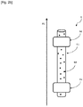
- the mixer 6 may comprise, according to a first embodiment, as shown in figure 2a , a single injector 62 positioned along the sheath 61.
- the mixer 6 may include two injectors 62, as shown in figure 2b , positioned along the sheath 61.
- the invention is also applicable in the case where the mixer 6 comprises more than two injectors 62.
- the injector 62 is positioned, according to a second embodiment, at one end of the sheath 61 of the mixer 6 along the longitudinal axis A1.
- two injectors 62 can be positioned at different ends of the sheath 61 of the mixer 6 along the longitudinal axis A1, as shown in FIG. figure 3b .
- the mixer 6 can have more than two injectors 62 as long as the mass added by the number of injectors 62 does not penalize the lift and the overall weight of the variable portability device 1.
- the sheath 61 of the mixer 6 which extends along the longitudinal axis A1, may include a secondary part 611 of the sheath 61.
- the secondary part 611 of the sheath 61 takes the tubular shape of the sheath 61 and extends along a second axis A2 secant to the longitudinal axis A1 of the variable portability device 1.
- the second axis A2 is orthogonal to the longitudinal axis A1.
- the secondary part 611 of the sheath 61 comprises, like the sheath 61, at least one and preferably a plurality of perforations 63.
- the secondary part 611 of the sheath 61 is defined by a secondary section S2.
- the secondary section S2 is preferably identical to the section of the sheath S1.
- the secondary section S2 of the secondary part 611 of the sheath 61 may be different from the section of the sheath S1.
- This embodiment shown in figure 4 makes it possible to increase the potential exchange surface between the air injected through the perforations 63 of the sheath 61 and of the secondary part 611 and the gas of density lower than the mass air volume. In this way, the homogenization of the mixture is improved.
- the invention is based on the injection of a so-called heavy gas onto a so-called light gas contained in the hermetic enclosure 4.
- This injection (that is to say the injection of air into the hermetic enclosure 4 ) is advantageously carried out over a large area, along the sheath 61 of the mixer 6, in order to obtain an optimum mixture between the two gases.
- This results in the formation of convection cells which make it possible to improve the mixing of the gases and the heat transfer with the external medium 3.
- the invention takes advantage of an injection of air into the sheath 61 and of the mixing of the gases. gas in the hermetic enclosure 4 to provide good controllability of the variable portability device 1 during its descent.
Landscapes
- Engineering & Computer Science (AREA)
- Mechanical Engineering (AREA)
- Aviation & Aerospace Engineering (AREA)
- Processing And Handling Of Plastics And Other Materials For Molding In General (AREA)
- Air Transport Of Granular Materials (AREA)
- Refuse Collection And Transfer (AREA)
- Jet Pumps And Other Pumps (AREA)
Abstract
• une enceinte hermétique (4) sous pression accueillant un gaz de masse volumique inférieure à la masse volumique de l'air ;
• un mélangeur (6) disposé au moins partiellement à l'intérieur de l'enceinte hermétique (4) configuré pour introduire de l'air à l'intérieur de l'enceinte hermétique (4).
Description
- La présente invention concerne le domaine des dispositifs de portabilité variable utilisant un gaz plus léger que l'air pour s'élever dans l'atmosphère. Plus précisément, l'invention a trait aux dispositifs de portabilité variable munis d'un unique réservoir pour stocker sous pression le gaz plus léger que l'air tel que l'hélium, le néon, le méthane, l'éthane et l'hydrogène.
- Un dispositif de portabilité variable peut être interprété comme une plateforme dirigeable stratosphérique à enveloppe souple pressurisée, connue sous l'appellation anglo-saxonne « Blimp ».
- Traditionnellement, les dispositifs de portabilité variable sont dotés de plusieurs ballonnets complètement hermétiques contenant le gaz plus léger que l'air. Ce sont ces ballonnets emplis du gaz plus léger que l'air qui assurent la portance des dispositifs de portabilité variable. Ces ballonnets sont compris dans une structure souple formant l'enveloppe des dispositifs de portabilité variable. Le reste du volume de l'enveloppe est occupé par de l'air. Pour monter, de l'air est éjecté et pour descendre, de l'air est injecté. La multiplicité des ballonnets d'air garantit la stabilité statique longitudinale quel que soit le taux de remplissage en air.
- Ce modèle est particulièrement apprécié pour les dispositifs de portabilité variable troposphériques, là où la masse volumique de l'air est forte. Cependant, dans le cas de dispositifs de portabilité variable stratosphériques, c'est-à-dire, des dispositifs de portabilité variable dont l'altitude de croisière s'établit au-delà de la tropopause, la masse volumique de l'air est très inférieure à la masse volumique de l'air dans la troposphère. La masse des dispositifs de portabilité variable stratosphériques doit donc être diminuée afin de permettre aux dispositifs de portabilité variable de s'élever jusqu'à ces altitudes.
- Or, la multiplicité des structures (l'enveloppe et les ballonnets) a tendance à fortement augmenter la masse du dispositif de portabilité variable.
- L'utilisation d'un unique réservoir hermétique permettrait d'éviter l'utilisation de plusieurs ballonnets et réduirait fortement la masse embarquée.
- Selon l'art antérieur décrit précédemment, le gaz plus léger que l'air étant contenu dans les ballonnets, il n'est jamais en contact direct avec l'air injecté dans l'enveloppe du dispositif de portabilité variable.
- Une solution consistant à injecter de l'air directement dans un unique réservoir n'est pas viable. Le mélange hétérogène entre le gaz plus léger que l'air et l'air qui en résulte peut induire une instabilité en assiette du dispositif de portabilité variable, c'est-à-dire une trop grande différence angulaire entre le plan horizontal et l'axe longitudinal du dispositif de portabilité variable stratosphérique. Cette instabilité peut s'accroître jusqu'à incliner totalement le dispositif de portabilité variable stratosphérique à la verticale. En effet, le gaz plus léger que l'air ayant une masse volumique plus faible que la masse volumique de l'air, le gaz plus léger que l'air se disposerait naturellement dans la partie haute du réservoir laissant l'air dans la partie basse du réservoir du dispositif de portabilité variable stratosphérique. Autrement dit, dans le cas d'un ballonnet unique, l'injection d'air entraine une migration de l'air vers le bas du réservoir et génère cette instabilité en assiette. Le phénomène est le même dans le cas où l'air est injecté autour des ballonnets et est mal mélangé. L'air, comme dit précédemment, plus dense que le gaz plus léger que l'air, migre vers le bas de l'enveloppe. La disposition n'étant pas homogène sur l'axe longitudinal du dispositif de portabilité variable stratosphérique, une instabilité de l'angle de l'assiette apparait.
- Lors des phases de variation de la portance, comme en phase de descente, il est donc nécessaire d'obtenir un mélange homogène à l'intérieur d'un potentiel unique réservoir afin d'assurer la pilotabilité d'un tel dispositif de portabilité variable stratosphérique.
- L'invention vise à pallier tout ou partie des problèmes cités plus haut en proposant un dispositif de portabilité variable comprenant mélangeur capable d'assurer un mélange homogène entre de l'air et un gaz plus léger que l'air au sein d'une unique enceinte hermétique sous pression.
- A cet effet, l'invention a pour objet un dispositif de portabilité variable caractérisé en ce qu'il comporte :
- une enceinte hermétique sous pression accueillant un gaz de masse volumique inférieure à la masse volumique de l'air ;
- un mélangeur disposé au moins partiellement à l'intérieur de l'enceinte hermétique configuré pour introduire de l'air à l'intérieur de l'enceinte hermétique.
- Selon un aspect de l'invention, le mélangeur comprend une gaine pourvue d'au moins une perforation et au moins un injecteur d'air dans la gaine.
- Selon un aspect de l'invention, la gaine est obtenue à partir d'un tissu poreux.
- Selon un aspect de l'invention, le dispositif de portabilité variable s'étend selon un premier axe longitudinal et la gaine possède une forme de tube s'étendant sensiblement selon le premier axe longitudinal du dispositif de portabilité variable.
- Selon un aspect de l'invention, la gaine s'étend selon un deuxième axe sécant au premier axe longitudinal du dispositif de portabilité variable.
- Selon un aspect de l'invention, au moins un injecteur est placé le long de la gaine du mélangeur selon le premier axe longitudinal du dispositif de portabilité variable.
- Selon un aspect de l'invention, au moins un injecteur est placé à une extrémité de la gaine du mélangeur.
- Selon un aspect de l'invention, une section de la gaine du mélangeur sensiblement perpendiculaire au premier axe longitudinal est définie par une dimension caractéristique supérieure à 15 centimètres.
- Selon un aspect de l'invention, la section de la gaine du mélangeur sensiblement perpendiculaire au premier axe longitudinal est définie par une dimension caractéristique inférieure à 250 centimètres.
- L'invention sera mieux comprise et d'autres avantages apparaîtront à la lecture de la description détaillée d'un mode de réalisation donné à titre d'exemple, description illustrée par le dessin joint dans lequel :
- [
Fig.1a ] lafigure 1a représente une vue latérale schématisée d'une vue en coupe du dispositif de portabilité variable selon l'invention ; - [
Fig.1b ] lafigure 1b représente une vue frontale schématisée d'une vue en coupe du dispositif de portabilité variable selon l'invention ; - [
Fig.2a ] lafigure 2a représente une vue schématisée du mélangeur du dispositif de portabilité variable selon un premier mode de réalisation. - [
Fig.2b ] lafigure 2b représente une variante du premier mode de réalisation du mélangeur du dispositif de portabilité variable. - [
Fig.3a ] lafigure 3a représente une vue schématisée du mélangeur du dispositif de portabilité variable selon un deuxième mode de réalisation. - [
Fig.3b ] lafigure 3b représente une variante du deuxième mode de réalisation du mélangeur du dispositif de portabilité variable. - [
Fig.4 ] lafigure 4 représente une vue schématisée du mélangeur du dispositif de portabilité variable selon un troisième mode de réalisation. - Par souci de clarté, les mêmes éléments porteront les mêmes repères dans les différentes figures.
- La
figure 1a représente une vue latérale schématisée d'une vue en coupe d'un dispositif de portabilité variable 1. La vue en coupe de lafigure 1a est réalisée selon un plan vertical comprenant un axe longitudinal A1 du dispositif de portabilité variable 1. Lafigure 1b représente une vue frontale schématisée d'une vue en coupe du dispositif de portabilité variable 1. La vue en coupe de lafigure 1b est réalisée selon un plan vertical perpendiculaire à l'axe longitudinal A1 du dispositif de portabilité variable 1. Le dispositif de portabilité variable 1 comporte une enceinte hermétique 4 sous pression destinée à accueillir un gaz de masse volumique inférieure à la masse volumique de l'air. Cette enceinte hermétique 4 peut correspondre, d'un point de vue extérieur à l'enveloppe du dispositif de portabilité variable 1. L'enceinte hermétique 4 est donc au contact, suivant une face externe 41, d'un milieu extérieur 3, et, suivant une face interne 42, du gaz de masse volumique inférieur à la masse volumique de l'air. L'enceinte hermétique 4 assure l'étanchéité entre le milieu extérieur 3 et le gaz contenu dans l'enceinte hermétique 4. Toutefois l'invention s'applique aussi avec un ballonnet additionnel contenant le gaz plus léger que l'air qui assure l'étanchéité. Dans ce cas, le ballonnet additionnel joue le rôle de l'enceinte hermétique 4. - Le dispositif de portabilité variable 1 comporte également un mélangeur 6, disposé partiellement dans l'enceinte hermétique 4 capable d'introduire de l'air à l'intérieur de l'enceinte hermétique 4 et de mélanger cet air avec le gaz de masse volumique inférieure à la masse volumique de l'air à l'intérieur de l'enceinte hermétique 4. En effet, le mélangeur 6 comprend une gaine 61 disposée à l'intérieur de l'enceinte hermétique 4 et un injecteur 62 connecté d'une part à la gaine 61 et d'autre part au milieu extérieur 3. De cette manière, l'injecteur 62 permet d'injecter de l'air du milieu extérieur 3 à l'intérieur de la gaine 61.
- Le mélangeur 6 est positionné contre une partie supérieure 43 de la face interne 42 de l'enceinte hermétique 4. Plus précisément, la gaine 61 du mélangeur 6 est positionnée contre la partie supérieure 43 de l'enceinte hermétique 4 et l'injecteur 62 transperce la partie supérieure 43 de l'enceinte hermétique 4 afin de pouvoir communiquer avec l'air du milieu extérieur 3. Plus généralement, l'invention s'applique avec un injecteur 62 connecté à la gaine 61, quel que soit son positionnement au niveau de la gaine 61.
- De cette manière, l'injecteur 62 permet d'injecter de l'air provenant du milieu extérieur 3 dans la gaine 61. Ainsi, l'air passe à travers la gaine 61 de manière homogène et se diffuse dans l'enceinte hermétique 4.
- La gaine 61 du mélangeur 6 prend avantageusement la forme d'un tube et s'étend sensiblement selon l'axe longitudinal A1 qui est défini comme l'axe traversant horizontalement le dispositif de portabilité variable 1. Ainsi, la gaine 61 peut prendre toute forme de tube comme par exemple et de façon non limitative un tube à section carré ou un tube à section circulaire. Avantageusement, la gaine 61 est souple et prend naturellement la forme d'un tube cylindrique. Selon l'invention, la gaine 61 peut prendre toute autre forme occupant une portion de volume dans l'enceinte hermétique 4.
- La gaine 61 peut être obtenue à partir d'un matériau rigide comme du polychlorure de vinyle ou autre matériau plastique rigide. Avantageusement, la gaine 61 est obtenue à partir d'un matériau souple comme un tissu. Ainsi, la masse de la gaine 61 est réduite.
- En outre, la gaine 61 peut être définie par une section de gaine S1 qui est la section du tube. Cette section peut être une section carrée pour une gaine 61 en tube à section carré ou peut être une section circulaire pour une gaine 61 cylindrique. La section de gaine S1 est définie par une dimension caractéristique D1. Pour une section de gaine S1 carrée, la dimension caractéristique D1 peut être une section droite et pour une section de gaine S1 circulaire, la dimension caractéristique D1 peut être le diamètre. Avantageusement, la dimension caractéristique D1 est le diamètre de la section de la gaine S1 circulaire. La dimension caractéristique D1 est une longueur qui dépend des dimensions du dispositif de portabilité variable 1. Néanmoins, la dimension caractéristique D1 peut être définie comme une longueur comprise entre 15 centimètres et 250 centimètres. Idéalement, la dimension caractéristique D1 est une longueur de 100 centimètres.
- De plus, comme le montrent les
figures 2a et2b , qui représentent la gaine 61 accompagnée d'un injecteur 62 pour lafigure 2a et de deux injecteurs pour lafigure 2b , la gaine 61 est percée dans son entièreté de multiples perforations 63. Il s'agit d'un exemple d'application. L'invention concerne aussi le cas où la gaine 61 est partiellement percée, c'est-à-dire avec une perforation 63 au minimum, et avantageusement une pluralité de perforations 63. - Les perforations 63 de la gaine 61 permettent d'obtenir un échange direct entre l'air injecté par l'injecteur 62 et le gaz de masse volumique inférieure à la masse volumique de l'air. Ainsi, des échanges convectifs peuvent apparaitre entre l'air du milieu extérieur 3 injecté par l'injecteur 62 et le gaz de masse volumique inférieure à la masse volumique de l'air. En effet, l'air injecté dans la gaine 61 à l'aide de l'injecteur 62 crée une surpression à l'intérieur de la gaine 61. L'évacuation de l'air en surplus au sein de la gaine 61 se fait alors par l'intermédiaire des perforations 63. La densité de l'air injecté étant plus importante que celle du gaz de masse volumique inférieure à la masse volumique de l'air, l'air injecté migre naturellement vers une partie inférieure 44 de l'enceinte hermétique 4 ce qui crée une cellule de convection qui favorise le mélange dans l'enceinte hermétique 4.
- De manière profitable, le tissu à l'origine de la gaine 61 est poreux. En effet, la porosité est définie comme l'ensemble des vides d'un matériau solide. Or un vide dans un matériau solide peut être interprété comme une perforation. Un tissu poreux est donc un tissu doté de multiples perforations 63. Ainsi, à titre d'exemple, la gaine 61 est obtenue à partir d'un tissu poreux afin d'améliorer du mieux possible le passage de l'air injecté par l'injecteur 62 de la gaine 61 vers l'enceinte hermétique 4. Les multiples perforations 63, obtenues soit par des perforations en tant que telles ou soit via la porosité de la gaine, permettent d'augmenter la surface de contact entre l'air injecté et le gaz présent dans l'enceinte hermétique 4. En effet, la zone de mélange est assimilable à un triangle isocèle de sommet principal la zone d'injection de l'air. La surface de contact est alors constituée par les côtés du triangle ainsi formé. La surface de la zone de mélange entre les deux gaz ainsi augmentée contribue au bon mélange de l'air dans le gaz de l'enceinte hermétique 4.
- Le mélangeur 6 peut comporter selon un premier mode de réalisation, comme représenté sur la
figure 2a , un unique injecteur 62 positionné le long de la gaine 61. - Par ailleurs, le mélangeur 6 peut comporter deux injecteurs 62, comme représenté sur la
figure 2b , positionnés le long de la gaine 61. L'invention est également applicable au cas où le mélangeur 6 comprend plus de deux injecteurs 62. - Préférentiellement, comme représenté en
figure 3a , l'injecteur 62 est positionné, selon un deuxième mode de réalisation, à une extrémité de la gaine 61 du mélangeur 6 suivant l'axe longitudinal A1. - De la même manière, deux injecteurs 62 peuvent être positionnés à des extrémités différentes de la gaine 61 du mélangeur 6 suivant l'axe longitudinal A1, comme représenté sur la
figure 3b . Le mélangeur 6 peut comporter plus de deux injecteurs 62 tant que la masse ajoutée par le nombre d'injecteur 62 ne pénalise pas la portance et le poids global du dispositif de portabilité variable 1. - Enfin, un troisième mode de réalisation, représenté en
figure 4 , peut être envisagé. La gaine 61 du mélangeur 6 qui s'étend selon l'axe longitudinal A1, peut comprendre une partie secondaire 611 de la gaine 61. La partie secondaire 611 de la gaine 61 prend la forme tubulaire de la gaine 61 et s'étend selon un deuxième axe A2 sécant à l'axe longitudinal A1 du dispositif de portabilité variable 1. Dans un mode de réalisation préférentiel, le deuxième axe A2 est orthogonal à l'axe longitudinal A1. La partie secondaire 611 de la gaine 61 comprend, comme la gaine 61, au moins une et préférentiellement une pluralité de perforations 63. - En outre, la partie secondaire 611 de la gaine 61 est définie par une section secondaire S2. La section secondaire S2 est, préférentiellement, identique à la section de la gaine S1. Cependant, la section secondaire S2 de la partie secondaire 611 de la gaine 61 peut être différente de la section de la gaine S1.
- Ce mode de réalisation représenté en
figure 4 permet d'augmenter la surface potentielle d'échange entre l'air injecté à travers les perforations 63 de la gaine 61 et de la partie secondaire 611 et le gaz de masse volumique inférieure à la masse volumique de l'air. De cette manière, l'homogénéisation du mélange s'en trouve améliorée. - L'invention repose sur l'injection d'un gaz dit lourd sur un gaz dit léger contenu dans l'enceinte hermétique 4. Cette injection (c'est-à-dire l'injection de l'air dans l'enceinte hermétique 4) se fait avantageusement sur une grande surface, le long de la gaine 61 du mélangeur 6, afin d'obtenir un mélange optimal entre les deux gaz. Il en résulte la formation de cellules de convection qui permettent d'améliorer le mélange des gaz et le transfert thermique avec le milieu extérieur 3. Ainsi, l'invention tire profit d'une injection d'air dans la gaine 61 et du mélange des gaz dans l'enceinte hermétique 4 pour offrir une bonne pilotabilité du dispositif de portabilité variable 1 pendant sa descente.
Claims (8)
- Dispositif de portabilité variable (1) caractérisé en ce qu'il comporte :• une enceinte hermétique (4) sous pression accueillant un gaz de masse volumique inférieure à la masse volumique de l'air l'air en contact avec un milieu extérieur (3) ;• un mélangeur (6) disposé au moins partiellement à l'intérieur de l'enceinte hermétique (4) configuré pour introduire de l'air à l'intérieur de l'enceinte hermétique (4), le mélangeur (4) comprenant une gaine (61) pourvue d'au moins une perforation (63) et au moins un injecteur (62), connecté au milieu extérieur (3), d'air dans la gaine (61).
- Dispositif de portabilité variable (1) selon la revendication 1, dans lequel la gaine (61) est obtenue à partir d'un tissu poreux.
- Dispositif de portabilité variable (1) selon l'une des revendications 1 à 2, s'étendant selon un premier axe longitudinal (A1), dans lequel la gaine (61) possède une forme de tube s'étendant sensiblement selon le premier axe longitudinal (A1) du dispositif de portabilité variable (1).
- Dispositif de portabilité variable (1) selon la revendication 3, dans lequel la gaine (61) s'étend selon un deuxième axe (A2) sécant au premier axe longitudinal (A1) du dispositif de portabilité variable (1).
- Dispositif de portabilité variable (1) selon l'une des revendications 1 à 4, dans lequel l'au moins un injecteur (62) est placé le long de la gaine (61) du mélangeur (6) selon le premier axe longitudinal (A1) du dispositif de portabilité variable (1).
- Dispositif de portabilité variable (1) selon la revendication 5, dans lequel l'au moins un injecteur (62) est placé à une extrémité de la gaine (61) du mélangeur (6).
- Dispositif de portabilité variable (1) selon l'une des revendications 3 à 6, dans lequel une section de la gaine (S1) du mélangeur (6) sensiblement perpendiculaire au premier axe longitudinal (A1) est définie par une dimension caractéristique (D1) supérieure à 15 centimètres.
- Dispositif de portabilité variable (1) selon l'une des revendications 3 à 7, dans lequel la section de la gaine (S1) du mélangeur sensiblement perpendiculaire au premier axe longitudinal (A1) est définie par une dimension caractéristique (D1) inférieure à 250 centimètres.
Applications Claiming Priority (1)
| Application Number | Priority Date | Filing Date | Title |
|---|---|---|---|
| FR2001399A FR3107251B1 (fr) | 2020-02-13 | 2020-02-13 | Dispositif de portabilite variable comprenant un diffiseur anti stratification |
Publications (3)
| Publication Number | Publication Date |
|---|---|
| EP3868646A1 true EP3868646A1 (fr) | 2021-08-25 |
| EP3868646C0 EP3868646C0 (fr) | 2024-05-15 |
| EP3868646B1 EP3868646B1 (fr) | 2024-05-15 |
Family
ID=71661944
Family Applications (1)
| Application Number | Title | Priority Date | Filing Date |
|---|---|---|---|
| EP21155129.6A Active EP3868646B1 (fr) | 2020-02-13 | 2021-02-04 | Dispositif de portabilite variable comprenant un diffuseur anti stratification |
Country Status (6)
| Country | Link |
|---|---|
| US (1) | US11524760B2 (fr) |
| EP (1) | EP3868646B1 (fr) |
| JP (1) | JP7820912B2 (fr) |
| CN (1) | CN113247231A (fr) |
| ES (1) | ES2981505T3 (fr) |
| FR (1) | FR3107251B1 (fr) |
Citations (3)
| Publication number | Priority date | Publication date | Assignee | Title |
|---|---|---|---|---|
| US3063657A (en) * | 1959-12-21 | 1962-11-13 | Ernest A Coester | Balloon and method of inflating the same |
| WO1995014607A1 (fr) * | 1993-11-22 | 1995-06-01 | Lockheed Martin Corporation | Systeme de ballonnets pour un aeronef plus leger que l'air |
| CN108298058A (zh) * | 2018-03-31 | 2018-07-20 | 丹阳昊天飞行器技术有限公司 | 一种多级减压式充气装置 |
Family Cites Families (7)
| Publication number | Priority date | Publication date | Assignee | Title |
|---|---|---|---|---|
| US1475210A (en) * | 1923-11-27 | upson | ||
| US5538203A (en) * | 1994-06-20 | 1996-07-23 | Lockheed Corporation | Ballonet system for a lighter-than-air vehicle |
| JP3952255B2 (ja) * | 2001-08-06 | 2007-08-01 | 独立行政法人情報通信研究機構 | 飛行船の吸排気方法および装置 |
| FR3008500B1 (fr) * | 2013-07-10 | 2015-09-04 | Liebherr Aerospace Toulouse Sas | Trompe de melange de gaz destinee notamment a un systeme de chauffage |
| US9573671B1 (en) * | 2013-12-31 | 2017-02-21 | X Development Llc | Fabric diffuser for high flowrate inflation |
| US9090323B1 (en) * | 2014-02-12 | 2015-07-28 | Google Inc. | Controlling descent of a zero pressure balloon |
| CN107054611A (zh) * | 2017-04-05 | 2017-08-18 | 杭州东沣科技有限公司 | 一种飞艇囊体快速充气系统及方法 |
-
2020
- 2020-02-13 FR FR2001399A patent/FR3107251B1/fr active Active
-
2021
- 2021-02-04 EP EP21155129.6A patent/EP3868646B1/fr active Active
- 2021-02-04 ES ES21155129T patent/ES2981505T3/es active Active
- 2021-02-10 US US17/173,078 patent/US11524760B2/en active Active
- 2021-02-10 JP JP2021020040A patent/JP7820912B2/ja active Active
- 2021-02-18 CN CN202110187444.0A patent/CN113247231A/zh active Pending
Patent Citations (3)
| Publication number | Priority date | Publication date | Assignee | Title |
|---|---|---|---|---|
| US3063657A (en) * | 1959-12-21 | 1962-11-13 | Ernest A Coester | Balloon and method of inflating the same |
| WO1995014607A1 (fr) * | 1993-11-22 | 1995-06-01 | Lockheed Martin Corporation | Systeme de ballonnets pour un aeronef plus leger que l'air |
| CN108298058A (zh) * | 2018-03-31 | 2018-07-20 | 丹阳昊天飞行器技术有限公司 | 一种多级减压式充气装置 |
Also Published As
| Publication number | Publication date |
|---|---|
| JP7820912B2 (ja) | 2026-02-26 |
| FR3107251A1 (fr) | 2021-08-20 |
| ES2981505T3 (es) | 2024-10-09 |
| EP3868646C0 (fr) | 2024-05-15 |
| JP2021127113A (ja) | 2021-09-02 |
| EP3868646B1 (fr) | 2024-05-15 |
| CN113247231A (zh) | 2021-08-13 |
| FR3107251B1 (fr) | 2022-09-09 |
| US11524760B2 (en) | 2022-12-13 |
| US20210253217A1 (en) | 2021-08-19 |
Similar Documents
| Publication | Publication Date | Title |
|---|---|---|
| EP0042784B1 (fr) | Réservoir à tension superficielle | |
| EP0202172B1 (fr) | Récipient pour gaz liquide, incorporé ou non dans un appareil d'utilisation | |
| EP0265319B1 (fr) | Procédé, cellule et dispositif de cristallogénèse, notamment par vaisseau spatial | |
| WO1986003469A1 (fr) | Ballon aerostatique pilotable | |
| FR2887638A1 (fr) | Lentille a focale variable a variation de pression interne reduite | |
| EP3868646B1 (fr) | Dispositif de portabilite variable comprenant un diffuseur anti stratification | |
| EP0132175A1 (fr) | Réservoir de stockage de liquide à confinement capillaire | |
| CA1331314C (fr) | Procede et dispositif pour declencher une avalanche | |
| EP0681924A1 (fr) | Article d'écriture à encre liquide, notamment à base de solvant | |
| FR3068013B1 (fr) | Dispositif de dosage destine a equiper un recipient et recipient comprenant un tel dispositif | |
| LU83809A1 (fr) | Filtre a cigarette | |
| EP4165363B1 (fr) | Equipement pour système de déclenchement d'avalanches et système comprenant un tel équipement et une enceinte d'explosion | |
| FR2764395A1 (fr) | Cable a tube etanche comprenant au moins un conducteur optique | |
| EP3187410A1 (fr) | Dirigeable hydride a enveloppe exterieure souple et compartimentee | |
| EP0043777B1 (fr) | Dispositif de stockage de liquide utilisant la tension superficielle de celui-ci | |
| EP2393714B1 (fr) | Réservoir cryogénique et lanceur supatial comportant un tel réservoir | |
| FR2472075A1 (en) | Tunnel anchor bolt for rock - bolt is surrounded by cylindrical cover with tubes to introduce tamping material | |
| EP0500663A1 (fr) | Diffuseur de liquide par evaporation a partir d'une substance absorbante poreuse | |
| WO2023021250A1 (fr) | Cuve de stockage et/ou de transport de gaz liquide destinée à un navire | |
| FR2610071A1 (fr) | Soupape en particulier pour le degazage de reservoirs de carburant de vehicules automobiles | |
| FR2601706A1 (fr) | Procede d'ancrage d'un pieu de fondation dans le sol et dispositif pour la mise en oeuvre de ce procede | |
| FR3099063A1 (fr) | Extincteur pyrotechnique pour véhicule | |
| FR3134382A1 (fr) | Dispositif recharge en vin ou spiritueux d’un contenant final, ensemble de recharge comprenant un tel dispositif et procédé de mise en œuvre | |
| CH554191A (fr) | Appareil pour la diffusion de gaz dans un liquide. | |
| FR3163997A1 (fr) | Injecteur pour un réservoir de gaz et réservoir équipé d’un tel injecteur. |
Legal Events
| Date | Code | Title | Description |
|---|---|---|---|
| PUAI | Public reference made under article 153(3) epc to a published international application that has entered the european phase |
Free format text: ORIGINAL CODE: 0009012 |
|
| STAA | Information on the status of an ep patent application or granted ep patent |
Free format text: STATUS: THE APPLICATION HAS BEEN PUBLISHED |
|
| AK | Designated contracting states |
Kind code of ref document: A1 Designated state(s): AL AT BE BG CH CY CZ DE DK EE ES FI FR GB GR HR HU IE IS IT LI LT LU LV MC MK MT NL NO PL PT RO RS SE SI SK SM TR |
|
| STAA | Information on the status of an ep patent application or granted ep patent |
Free format text: STATUS: REQUEST FOR EXAMINATION WAS MADE |
|
| 17P | Request for examination filed |
Effective date: 20220118 |
|
| RBV | Designated contracting states (corrected) |
Designated state(s): AL AT BE BG CH CY CZ DE DK EE ES FI FR GB GR HR HU IE IS IT LI LT LU LV MC MK MT NL NO PL PT RO RS SE SI SK SM TR |
|
| STAA | Information on the status of an ep patent application or granted ep patent |
Free format text: STATUS: EXAMINATION IS IN PROGRESS |
|
| 17Q | First examination report despatched |
Effective date: 20221219 |
|
| GRAP | Despatch of communication of intention to grant a patent |
Free format text: ORIGINAL CODE: EPIDOSNIGR1 |
|
| STAA | Information on the status of an ep patent application or granted ep patent |
Free format text: STATUS: GRANT OF PATENT IS INTENDED |
|
| INTG | Intention to grant announced |
Effective date: 20240108 |
|
| GRAS | Grant fee paid |
Free format text: ORIGINAL CODE: EPIDOSNIGR3 |
|
| GRAA | (expected) grant |
Free format text: ORIGINAL CODE: 0009210 |
|
| STAA | Information on the status of an ep patent application or granted ep patent |
Free format text: STATUS: THE PATENT HAS BEEN GRANTED |
|
| AK | Designated contracting states |
Kind code of ref document: B1 Designated state(s): AL AT BE BG CH CY CZ DE DK EE ES FI FR GB GR HR HU IE IS IT LI LT LU LV MC MK MT NL NO PL PT RO RS SE SI SK SM TR |
|
| RAP3 | Party data changed (applicant data changed or rights of an application transferred) |
Owner name: THALES |
|
| REG | Reference to a national code |
Ref country code: CH Ref legal event code: EP |
|
| REG | Reference to a national code |
Ref country code: DE Ref legal event code: R096 Ref document number: 602021013197 Country of ref document: DE |
|
| REG | Reference to a national code |
Ref country code: IE Ref legal event code: FG4D Free format text: LANGUAGE OF EP DOCUMENT: FRENCH |
|
| U01 | Request for unitary effect filed |
Effective date: 20240527 |
|
| U07 | Unitary effect registered |
Designated state(s): AT BE BG DE DK EE FI FR IT LT LU LV MT NL PT SE SI Effective date: 20240604 |
|
| PG25 | Lapsed in a contracting state [announced via postgrant information from national office to epo] |
Ref country code: IS Free format text: LAPSE BECAUSE OF FAILURE TO SUBMIT A TRANSLATION OF THE DESCRIPTION OR TO PAY THE FEE WITHIN THE PRESCRIBED TIME-LIMIT Effective date: 20240915 |
|
| REG | Reference to a national code |
Ref country code: ES Ref legal event code: FG2A Ref document number: 2981505 Country of ref document: ES Kind code of ref document: T3 Effective date: 20241009 |
|
| PG25 | Lapsed in a contracting state [announced via postgrant information from national office to epo] |
Ref country code: HR Free format text: LAPSE BECAUSE OF FAILURE TO SUBMIT A TRANSLATION OF THE DESCRIPTION OR TO PAY THE FEE WITHIN THE PRESCRIBED TIME-LIMIT Effective date: 20240515 |
|
| PG25 | Lapsed in a contracting state [announced via postgrant information from national office to epo] |
Ref country code: GR Free format text: LAPSE BECAUSE OF FAILURE TO SUBMIT A TRANSLATION OF THE DESCRIPTION OR TO PAY THE FEE WITHIN THE PRESCRIBED TIME-LIMIT Effective date: 20240816 |
|
| PG25 | Lapsed in a contracting state [announced via postgrant information from national office to epo] |
Ref country code: PL Free format text: LAPSE BECAUSE OF FAILURE TO SUBMIT A TRANSLATION OF THE DESCRIPTION OR TO PAY THE FEE WITHIN THE PRESCRIBED TIME-LIMIT Effective date: 20240515 |
|
| PG25 | Lapsed in a contracting state [announced via postgrant information from national office to epo] |
Ref country code: PL Free format text: LAPSE BECAUSE OF FAILURE TO SUBMIT A TRANSLATION OF THE DESCRIPTION OR TO PAY THE FEE WITHIN THE PRESCRIBED TIME-LIMIT Effective date: 20240515 Ref country code: NO Free format text: LAPSE BECAUSE OF FAILURE TO SUBMIT A TRANSLATION OF THE DESCRIPTION OR TO PAY THE FEE WITHIN THE PRESCRIBED TIME-LIMIT Effective date: 20240815 Ref country code: IS Free format text: LAPSE BECAUSE OF FAILURE TO SUBMIT A TRANSLATION OF THE DESCRIPTION OR TO PAY THE FEE WITHIN THE PRESCRIBED TIME-LIMIT Effective date: 20240915 Ref country code: HR Free format text: LAPSE BECAUSE OF FAILURE TO SUBMIT A TRANSLATION OF THE DESCRIPTION OR TO PAY THE FEE WITHIN THE PRESCRIBED TIME-LIMIT Effective date: 20240515 Ref country code: GR Free format text: LAPSE BECAUSE OF FAILURE TO SUBMIT A TRANSLATION OF THE DESCRIPTION OR TO PAY THE FEE WITHIN THE PRESCRIBED TIME-LIMIT Effective date: 20240816 Ref country code: RS Free format text: LAPSE BECAUSE OF FAILURE TO SUBMIT A TRANSLATION OF THE DESCRIPTION OR TO PAY THE FEE WITHIN THE PRESCRIBED TIME-LIMIT Effective date: 20240815 |
|
| PG25 | Lapsed in a contracting state [announced via postgrant information from national office to epo] |
Ref country code: CZ Free format text: LAPSE BECAUSE OF FAILURE TO SUBMIT A TRANSLATION OF THE DESCRIPTION OR TO PAY THE FEE WITHIN THE PRESCRIBED TIME-LIMIT Effective date: 20240515 |
|
| PG25 | Lapsed in a contracting state [announced via postgrant information from national office to epo] |
Ref country code: SK Free format text: LAPSE BECAUSE OF FAILURE TO SUBMIT A TRANSLATION OF THE DESCRIPTION OR TO PAY THE FEE WITHIN THE PRESCRIBED TIME-LIMIT Effective date: 20240515 Ref country code: RO Free format text: LAPSE BECAUSE OF FAILURE TO SUBMIT A TRANSLATION OF THE DESCRIPTION OR TO PAY THE FEE WITHIN THE PRESCRIBED TIME-LIMIT Effective date: 20240515 |
|
| PG25 | Lapsed in a contracting state [announced via postgrant information from national office to epo] |
Ref country code: SM Free format text: LAPSE BECAUSE OF FAILURE TO SUBMIT A TRANSLATION OF THE DESCRIPTION OR TO PAY THE FEE WITHIN THE PRESCRIBED TIME-LIMIT Effective date: 20240515 |
|
| PG25 | Lapsed in a contracting state [announced via postgrant information from national office to epo] |
Ref country code: SM Free format text: LAPSE BECAUSE OF FAILURE TO SUBMIT A TRANSLATION OF THE DESCRIPTION OR TO PAY THE FEE WITHIN THE PRESCRIBED TIME-LIMIT Effective date: 20240515 Ref country code: SK Free format text: LAPSE BECAUSE OF FAILURE TO SUBMIT A TRANSLATION OF THE DESCRIPTION OR TO PAY THE FEE WITHIN THE PRESCRIBED TIME-LIMIT Effective date: 20240515 Ref country code: RO Free format text: LAPSE BECAUSE OF FAILURE TO SUBMIT A TRANSLATION OF THE DESCRIPTION OR TO PAY THE FEE WITHIN THE PRESCRIBED TIME-LIMIT Effective date: 20240515 Ref country code: CZ Free format text: LAPSE BECAUSE OF FAILURE TO SUBMIT A TRANSLATION OF THE DESCRIPTION OR TO PAY THE FEE WITHIN THE PRESCRIBED TIME-LIMIT Effective date: 20240515 |
|
| REG | Reference to a national code |
Ref country code: DE Ref legal event code: R097 Ref document number: 602021013197 Country of ref document: DE |
|
| U20 | Renewal fee for the european patent with unitary effect paid |
Year of fee payment: 5 Effective date: 20250122 |
|
| PLBE | No opposition filed within time limit |
Free format text: ORIGINAL CODE: 0009261 |
|
| STAA | Information on the status of an ep patent application or granted ep patent |
Free format text: STATUS: NO OPPOSITION FILED WITHIN TIME LIMIT |
|
| 26N | No opposition filed |
Effective date: 20250218 |
|
| PG25 | Lapsed in a contracting state [announced via postgrant information from national office to epo] |
Ref country code: MC Free format text: LAPSE BECAUSE OF FAILURE TO SUBMIT A TRANSLATION OF THE DESCRIPTION OR TO PAY THE FEE WITHIN THE PRESCRIBED TIME-LIMIT Effective date: 20240515 |
|
| REG | Reference to a national code |
Ref country code: CH Ref legal event code: PL |
|
| PG25 | Lapsed in a contracting state [announced via postgrant information from national office to epo] |
Ref country code: CH Free format text: LAPSE BECAUSE OF NON-PAYMENT OF DUE FEES Effective date: 20250228 |
|
| PG25 | Lapsed in a contracting state [announced via postgrant information from national office to epo] |
Ref country code: IE Free format text: LAPSE BECAUSE OF NON-PAYMENT OF DUE FEES Effective date: 20250204 |
|
| U20 | Renewal fee for the european patent with unitary effect paid |
Year of fee payment: 6 Effective date: 20260119 |
|
| PGFP | Annual fee paid to national office [announced via postgrant information from national office to epo] |
Ref country code: GB Payment date: 20260119 Year of fee payment: 6 |
|
| PGFP | Annual fee paid to national office [announced via postgrant information from national office to epo] |
Ref country code: ES Payment date: 20260310 Year of fee payment: 6 |