EP3868593B1 - Power-transmission axle for vehicle and vehicle - Google Patents
Power-transmission axle for vehicle and vehicle Download PDFInfo
- Publication number
- EP3868593B1 EP3868593B1 EP19873723.1A EP19873723A EP3868593B1 EP 3868593 B1 EP3868593 B1 EP 3868593B1 EP 19873723 A EP19873723 A EP 19873723A EP 3868593 B1 EP3868593 B1 EP 3868593B1
- Authority
- EP
- European Patent Office
- Prior art keywords
- shaft
- vehicle
- segment
- traction
- flange
- Prior art date
- Legal status (The legal status is an assumption and is not a legal conclusion. Google has not performed a legal analysis and makes no representation as to the accuracy of the status listed.)
- Active
Links
Images



Classifications
-
- B—PERFORMING OPERATIONS; TRANSPORTING
- B60—VEHICLES IN GENERAL
- B60K—ARRANGEMENT OR MOUNTING OF PROPULSION UNITS OR OF TRANSMISSIONS IN VEHICLES; ARRANGEMENT OR MOUNTING OF PLURAL DIVERSE PRIME-MOVERS IN VEHICLES; AUXILIARY DRIVES FOR VEHICLES; INSTRUMENTATION OR DASHBOARDS FOR VEHICLES; ARRANGEMENTS IN CONNECTION WITH COOLING, AIR INTAKE, GAS EXHAUST OR FUEL SUPPLY OF PROPULSION UNITS IN VEHICLES
- B60K17/00—Arrangement or mounting of transmissions in vehicles
- B60K17/36—Arrangement or mounting of transmissions in vehicles for driving tandem wheels
-
- B—PERFORMING OPERATIONS; TRANSPORTING
- B60—VEHICLES IN GENERAL
- B60B—VEHICLE WHEELS; CASTORS; AXLES FOR WHEELS OR CASTORS; INCREASING WHEEL ADHESION
- B60B35/00—Axle units; Parts thereof ; Arrangements for lubrication of axles
- B60B35/12—Torque-transmitting axles
- B60B35/14—Torque-transmitting axles composite or split, e.g. half- axles; Couplings between axle parts or sections
-
- B—PERFORMING OPERATIONS; TRANSPORTING
- B60—VEHICLES IN GENERAL
- B60K—ARRANGEMENT OR MOUNTING OF PROPULSION UNITS OR OF TRANSMISSIONS IN VEHICLES; ARRANGEMENT OR MOUNTING OF PLURAL DIVERSE PRIME-MOVERS IN VEHICLES; AUXILIARY DRIVES FOR VEHICLES; INSTRUMENTATION OR DASHBOARDS FOR VEHICLES; ARRANGEMENTS IN CONNECTION WITH COOLING, AIR INTAKE, GAS EXHAUST OR FUEL SUPPLY OF PROPULSION UNITS IN VEHICLES
- B60K17/00—Arrangement or mounting of transmissions in vehicles
- B60K17/02—Arrangement or mounting of transmissions in vehicles characterised by arrangement, location, or kind of clutch
-
- B—PERFORMING OPERATIONS; TRANSPORTING
- B60—VEHICLES IN GENERAL
- B60K—ARRANGEMENT OR MOUNTING OF PROPULSION UNITS OR OF TRANSMISSIONS IN VEHICLES; ARRANGEMENT OR MOUNTING OF PLURAL DIVERSE PRIME-MOVERS IN VEHICLES; AUXILIARY DRIVES FOR VEHICLES; INSTRUMENTATION OR DASHBOARDS FOR VEHICLES; ARRANGEMENTS IN CONNECTION WITH COOLING, AIR INTAKE, GAS EXHAUST OR FUEL SUPPLY OF PROPULSION UNITS IN VEHICLES
- B60K17/00—Arrangement or mounting of transmissions in vehicles
- B60K17/22—Arrangement or mounting of transmissions in vehicles characterised by arrangement, location, or type of main drive shafting, e.g. cardan shaft
-
- B—PERFORMING OPERATIONS; TRANSPORTING
- B60—VEHICLES IN GENERAL
- B60K—ARRANGEMENT OR MOUNTING OF PROPULSION UNITS OR OF TRANSMISSIONS IN VEHICLES; ARRANGEMENT OR MOUNTING OF PLURAL DIVERSE PRIME-MOVERS IN VEHICLES; AUXILIARY DRIVES FOR VEHICLES; INSTRUMENTATION OR DASHBOARDS FOR VEHICLES; ARRANGEMENTS IN CONNECTION WITH COOLING, AIR INTAKE, GAS EXHAUST OR FUEL SUPPLY OF PROPULSION UNITS IN VEHICLES
- B60K17/00—Arrangement or mounting of transmissions in vehicles
- B60K17/34—Arrangement or mounting of transmissions in vehicles for driving both front and rear wheels, e.g. four wheel drive vehicles
- B60K17/348—Arrangement or mounting of transmissions in vehicles for driving both front and rear wheels, e.g. four wheel drive vehicles having differential means for driving one set of wheels, e.g. the front, at one speed and the other set, e.g. the rear, at a different speed
- B60K17/35—Arrangement or mounting of transmissions in vehicles for driving both front and rear wheels, e.g. four wheel drive vehicles having differential means for driving one set of wheels, e.g. the front, at one speed and the other set, e.g. the rear, at a different speed including arrangements for suppressing or influencing the power transfer, e.g. viscous clutches
-
- B—PERFORMING OPERATIONS; TRANSPORTING
- B60—VEHICLES IN GENERAL
- B60K—ARRANGEMENT OR MOUNTING OF PROPULSION UNITS OR OF TRANSMISSIONS IN VEHICLES; ARRANGEMENT OR MOUNTING OF PLURAL DIVERSE PRIME-MOVERS IN VEHICLES; AUXILIARY DRIVES FOR VEHICLES; INSTRUMENTATION OR DASHBOARDS FOR VEHICLES; ARRANGEMENTS IN CONNECTION WITH COOLING, AIR INTAKE, GAS EXHAUST OR FUEL SUPPLY OF PROPULSION UNITS IN VEHICLES
- B60K23/00—Arrangement or mounting of control devices for vehicle transmissions, or parts thereof, not otherwise provided for
- B60K23/08—Arrangement or mounting of control devices for vehicle transmissions, or parts thereof, not otherwise provided for for changing number of driven wheels, for switching from driving one axle to driving two or more axles
-
- B—PERFORMING OPERATIONS; TRANSPORTING
- B60—VEHICLES IN GENERAL
- B60K—ARRANGEMENT OR MOUNTING OF PROPULSION UNITS OR OF TRANSMISSIONS IN VEHICLES; ARRANGEMENT OR MOUNTING OF PLURAL DIVERSE PRIME-MOVERS IN VEHICLES; AUXILIARY DRIVES FOR VEHICLES; INSTRUMENTATION OR DASHBOARDS FOR VEHICLES; ARRANGEMENTS IN CONNECTION WITH COOLING, AIR INTAKE, GAS EXHAUST OR FUEL SUPPLY OF PROPULSION UNITS IN VEHICLES
- B60K23/00—Arrangement or mounting of control devices for vehicle transmissions, or parts thereof, not otherwise provided for
- B60K23/08—Arrangement or mounting of control devices for vehicle transmissions, or parts thereof, not otherwise provided for for changing number of driven wheels, for switching from driving one axle to driving two or more axles
- B60K23/0808—Arrangement or mounting of control devices for vehicle transmissions, or parts thereof, not otherwise provided for for changing number of driven wheels, for switching from driving one axle to driving two or more axles for varying torque distribution between driven axles, e.g. by transfer clutch
- B60K2023/0816—Arrangement or mounting of control devices for vehicle transmissions, or parts thereof, not otherwise provided for for changing number of driven wheels, for switching from driving one axle to driving two or more axles for varying torque distribution between driven axles, e.g. by transfer clutch for varying front-rear torque distribution with a central differential
- B60K2023/0833—Arrangement or mounting of control devices for vehicle transmissions, or parts thereof, not otherwise provided for for changing number of driven wheels, for switching from driving one axle to driving two or more axles for varying torque distribution between driven axles, e.g. by transfer clutch for varying front-rear torque distribution with a central differential for adding torque to the rear wheels
-
- B—PERFORMING OPERATIONS; TRANSPORTING
- B60—VEHICLES IN GENERAL
- B60K—ARRANGEMENT OR MOUNTING OF PROPULSION UNITS OR OF TRANSMISSIONS IN VEHICLES; ARRANGEMENT OR MOUNTING OF PLURAL DIVERSE PRIME-MOVERS IN VEHICLES; AUXILIARY DRIVES FOR VEHICLES; INSTRUMENTATION OR DASHBOARDS FOR VEHICLES; ARRANGEMENTS IN CONNECTION WITH COOLING, AIR INTAKE, GAS EXHAUST OR FUEL SUPPLY OF PROPULSION UNITS IN VEHICLES
- B60K23/00—Arrangement or mounting of control devices for vehicle transmissions, or parts thereof, not otherwise provided for
- B60K23/08—Arrangement or mounting of control devices for vehicle transmissions, or parts thereof, not otherwise provided for for changing number of driven wheels, for switching from driving one axle to driving two or more axles
- B60K2023/085—Arrangement or mounting of control devices for vehicle transmissions, or parts thereof, not otherwise provided for for changing number of driven wheels, for switching from driving one axle to driving two or more axles automatically actuated
- B60K2023/0866—Arrangement or mounting of control devices for vehicle transmissions, or parts thereof, not otherwise provided for for changing number of driven wheels, for switching from driving one axle to driving two or more axles automatically actuated with hydraulic means only
-
- B—PERFORMING OPERATIONS; TRANSPORTING
- B60—VEHICLES IN GENERAL
- B60Y—INDEXING SCHEME RELATING TO ASPECTS CROSS-CUTTING VEHICLE TECHNOLOGY
- B60Y2200/00—Type of vehicle
- B60Y2200/10—Road Vehicles
- B60Y2200/14—Trucks; Load vehicles, Busses
-
- B—PERFORMING OPERATIONS; TRANSPORTING
- B60—VEHICLES IN GENERAL
- B60Y—INDEXING SCHEME RELATING TO ASPECTS CROSS-CUTTING VEHICLE TECHNOLOGY
- B60Y2400/00—Special features of vehicle units
- B60Y2400/40—Actuators for moving a controlled member
- B60Y2400/406—Hydraulic actuators
-
- B—PERFORMING OPERATIONS; TRANSPORTING
- B60—VEHICLES IN GENERAL
- B60Y—INDEXING SCHEME RELATING TO ASPECTS CROSS-CUTTING VEHICLE TECHNOLOGY
- B60Y2400/00—Special features of vehicle units
- B60Y2400/40—Actuators for moving a controlled member
- B60Y2400/408—Pneumatic actuators
-
- B—PERFORMING OPERATIONS; TRANSPORTING
- B60—VEHICLES IN GENERAL
- B60Y—INDEXING SCHEME RELATING TO ASPECTS CROSS-CUTTING VEHICLE TECHNOLOGY
- B60Y2400/00—Special features of vehicle units
- B60Y2400/42—Clutches or brakes
- B60Y2400/421—Dog type clutches or brakes
Definitions
- This invention refers, in a general sense, to a propeller shaft of an automotive vehicle, which has a coupling and decoupling system to allow the selection of the vehicle's traction type, transmitting or not the power to the subsequent shaft.
- This invention also refers to an automotive vehicle comprising the present propeller shaft.
- automotive vehicles and particularly those intended for the transportation of goods, such as trucks, are usually pulled by their rear shaft having a powertrain formed by the engine and gearbox mounted at the front of the vehicle.
- the connection between the powertrain and the traction wheels is formed by a shaft, commonly called the cardan shaft, which, on the one hand, is connected to the output of the powertrain, usually the gearbox and, on the other hand, is connected to the differential of the shaft that is responsible for transmitting the power to the wheels.
- the vehicle may have a 6 ⁇ 2 or 6 ⁇ 4 traction configuration, i.e., of the six wheels of the vehicle, only two are pulled, usually the two wheels of the first rear shaft, or the four wheels of the two rear shafts are pulled.
- 6 ⁇ 2 or 6 ⁇ 4 traction configuration i.e., of the six wheels of the vehicle, only two are pulled, usually the two wheels of the first rear shaft, or the four wheels of the two rear shafts are pulled.
- they may also have an 8 ⁇ 4 or even 6 ⁇ 6 or 8 ⁇ 8 traction configuration.
- the traction configuration is, for example, a 6 ⁇ 2 configuration
- one of the rear shafts, the one not pulled can potentially be suspended and thus achieve a reduction in fuel consumption and tire wear. This is possible using some solutions that are already known, and where an air bag is generally used to suspend the shaft, thus taking advantage of the compressed air line fitted in these models of vehicles.
- a propeller shaft for a motor vehicle particularly those used for transporting loads with a traction configuration of 6 ⁇ 4 or 8 ⁇ 4, where said propeller shaft is equipped with technical, constructive and functional characteristics designed and developed to allow for the decoupling and coupling of at least one of the traction shafts in order to eliminate the problems, limitations and inconveniences of the solutions previously known to the state of the art, and as summarized above.
- Another aim of this invention is to provide a vehicle, such as those used for the transportation of loads, which is configured with traction of the 6 ⁇ 4 or 8 ⁇ 4 type, and equipped with at least one propeller shaft as mentioned above, installed in place of the conventional cardan shaft of the vehicle, allowing for the selection of the type of traction.
- the present invention refers to a propeller shaft and a vehicle as claimed in the appended set of claims.
- Figure 1 schematically represents a vehicle (V) intended for the transportation of cargo or goods, such as a truck known to the state of the art.
- This vehicle (V) as schematically represented in Figure 1 , may be, for example, a model manufactured and marketed by CNH Industrial N. V.
- the vehicle (V) comprises a control and operation cab (C) under which are provided a transmission powertrain (M), such as a combustion engine associated with a gearbox, which are mounted on a chassis (E) supported by a front shaft (TD), a first rear shaft (T1) and a second rear shaft (T2).
- a transmission powertrain such as a combustion engine associated with a gearbox
- TD front shaft
- T1 first rear shaft
- T2 second rear shaft
- these rear shafts (T1, T2) are pulled and, thus, will potentially be indicated as the first traction shaft (T1) and the second traction shaft (T2).
- the drive assembly (M) which is formed of the gearbox within which are arranged a series of gears and other components responsible for transmitting the power generated in the engine and, from which extends a first cardan shaft 1 to a first differential of the first traction shaft (T1) and, from the differential of the first traction shaft (T1), extends a second cardan shaft 2 to the differential of the second traction shaft (T2).
- the power is generally divided equally between the first and second differentials to the wheels of the first (T1) and second (T2) traction shafts.
- the differentials transmit the power to the wheels of each shaft in a normal way using a crown/pinion system and epicycloidal gears, which is already well known to persons skilled in the art and, thus, will not be explored in this case.
- other details of the vehicle (V) are represented in a schematic way and do not require further explanation, since they are known in conventional cargo transport vehicles.
- the present invention aims, precisely, to allow for the coupling or decoupling, selectively and according to the interests of the driver, of the second differential from the second traction shaft (T2), transforming the traction configuration from 6x4 to a 6x2 traction configuration.
- T2 second traction shaft
- the invention can obviously be used in any traction configuration where one wishes to activate or deactivate a second traction shaft, such as a 4 ⁇ 4 / 4 ⁇ 2, 8 ⁇ 4 / 8 ⁇ 2 traction configuration, etc.
- a transmission shaft 10 is shown, such as for coupling in a cardan shaft or replacing a conventional cardan shaft, which is specifically mounted between the first traction shaft (T1) and the second traction shaft (T2) of a vehicle (V).
- the shaft 10 can be mounted between the differentials of two rear traction shafts of a vehicle comprising, for example, a 6 ⁇ 4 traction configuration, or even replace the second cardan shaft 2.
- first rear shaft (T1) and the second rear shaft (T2) can have different assembly heights or can also be mounted to the suspension of the vehicle, being subject to oscillations in height and, consequently, at a distance from each other, crossheads 3 and 4 are provided at the ends of the shaft 10, which form the mechanical connection with the rest of the transmission powertrain of the vehicle.
- the shaft 10 comprises an assembly 5 of two concentric toothed shafts, which allow for the compensation of the distance that may exist between the first traction shaft (T1) and the second traction shaft (T2).
- both the crossheads 3 and 4, and the assembly 5 are mechanical constructions used in cardan shafts that are widely known and used in the state of the art, and can thus be replaced by any equivalent mechanical constructions, such as homokinetic joints or flanges associated with screws and nuts, in cases where the coupling is mounted on a long cardan shaft.
- the decision to choose crossheads, homokinetic joints or other mechanical construction elements does not alter the technical effects foreseen for the present invention.
- the present invention refers to a new propeller shaft 10 comprising a first shaft segment 12, which can be mounted on a power output, and a second shaft segment 13, which can be mounted on a power input to receive the power coming from the first shaft segment 12.
- Both shaft segments 12, 13 are concentrically mounted within a housing 11, so that the first shaft segment 12 can be rotated independently in relation to the second shaft segment 13, where this first shaft segment 12 comprises, on the one hand, a power input and, on the other hand, is mounted concentrically with the second shaft segment 13.
- the second shaft segment 13 also has, on one side, a toothed face (16) to receive a power input and, on the other side, it has a power output.
- first 12 and second 13 shaft segments are coupled and decoupled selectively by means of a flange 15, which is mounted concentrically on the first shaft segment and comprises a toothed face for the respective coupling with the toothed face of the second shaft segment. Furthermore, this flange 15 can move between a coupled and uncoupled position due to the coaxial displacement along the said first shaft segment 12.
- the said flange 15 is driven by a coupler 14 formed of an actuator 14a that possesses a shaft 18c equipped with a means of return 20, and a fork 17 connected to said flange 15 provided with a groove in its internal diameter for connection with a grooved part 12a provided for in the first shaft segment 12, and teeth 15a on its lateral face to enable the connection with the teeth 16a arranged on the toothed face 16 of the second shaft segment 13.
- the propeller shaft 10, according to the present invention can be installed in place of the second cardan shaft 2, between the first traction shaft (T1) and the second traction shaft (T2) of said vehicle (V).
- the first shaft segment 12 is mounted next at a power output deriving from the first cardan shaft 1
- the second shaft segment 13 is mounted on the power input, for example, on the differential of the second traction shaft (T2), said shaft segments 12, 13 being selectively connected through said coupler 14 which is responsible for blocking and transmitting the power between the shaft segments 12, 13.
- said housing 11 comprises sealant elements 8 to securely hold a lubricating and cooling fluid in contact with said shaft segments 12, 13, as well as with the actuator 14.
- first shaft segment 12 can be mounted on a power output and the second shaft segment 13 can be mounted on a power input
- configuration may be reversed, i.e., the first shaft segment 12 can be mounted on a power input and the second shaft segment 13 can be mounted on a power output without any prejudice or difference in relation to the technical effect achieved by the present invention.
- said toothed face 16 may be a fixed flange that is provided with a grooved surface on its inner diameter for connection with a respective grooved part 13a positioned at the end of the second shaft segment 13.
- the toothed face 16 or said fixed flange possesses teeth 16a on its lateral face to enable the connection with the teeth 15a arranged on the side face of the mobile flange 15 of the first shaft segment 12.
- said driver 14a can be of any model and use different appropriate means, such as, but not limited to, mechanical, magnetic, electrical or hydraulic means or a combination thereof, provided that it can enable the movement of said fork 17 between at least two positions and, consequently, achieve coupling or decoupling between the said first and second shaft segments 12, 13.
- said driver 14a comprises a chamber 18 with airtight closure that is formed by a fixed cover 18a installed in a branch 11a of the housing 11, and inside said chamber 18 a mobile piston 18b is positioned that is supported on the shaft 18c which supports the aforementioned fork 17 and the means of return 20.
- the fixed cover 18a of the driver 14a is equipped with a channel 19a, that is fluidly connected to the hydraulic or pneumatic system of the vehicle (V) for feeding the chamber 18.
- V hydraulic or pneumatic system of the vehicle
- the driver is able to alter the configuration and traction of the vehicle from a configuration of 6 ⁇ 2 to 6 ⁇ 4 by simply activating and feeding said chamber 18 of the driver 14a.
- the fixed cover 18a of the driver 14a comprises a complementary input 19b to allow for the installation of sensors, for example, a sensor for monitoring the pressure inside the chamber 18.
- compressed air or hydraulic fluid is used.
- the use of these components as one of the ways to enable the displacement of the fork 17 and, consequently, the mobile flange 15, is appropriate since the lines of compressed air and, potentially, of hydraulic fluid already present in most commercial vehicles and machinery can be used.
- ambient pressure and “increased pressure” with ambient pressure as a reference
- other pressure differentials that are not necessarily based on atmospheric pressure such as the base pressure can be used, including higher or even negative pressures, using a vacuum, provided that the pressure differential applied in the chamber 18 is sufficient to cause a shift of the mobile flange 15 through an axial movement, as indicated above.
- the means of return 20 may be a helical spring, ensuring that the coupler 14 remains in a predetermined position, such as a decoupled standard position, as represented in the drawings, or, conversely, a coupled standard position.
- the means of return can be suppressed if other forms of displacement of the fork 17 are used, such as magnetic or electromechanical means. Nevertheless, other means of return can also be provided, such as magnetic, mechanical or hydraulic means, etc.
- the coupling and decoupling of the coupler 14 must be done with the vehicle stationary, that is, without the first shaft segment 12 rotating, however, though less advantageous, there is nothing to prevent such coupling and/or decoupling being done with the vehicle in motion.
- the present invention also refers to a vehicle (V) for the transportation of cargo or goods, which comprises a control and operation cabin (C) and under which are provided a transmission powertrain (M), such as a combustion engine associated with a gearbox, which are mounted on a chassis (E), which is supported by a front shaft (TD), a first rear traction shaft (T1) and a second rear traction shaft (T2), connected by a propeller shaft 10, like that observed above.
- a transmission powertrain such as a combustion engine associated with a gearbox
- said vehicle (V) is a truck, such as those used in the road transportation of cargo or goods and, more particularly, which possesses the traction configuration of the 6 ⁇ 4 or 8 ⁇ 4 type, or the like.
Landscapes
- Engineering & Computer Science (AREA)
- Mechanical Engineering (AREA)
- Chemical & Material Sciences (AREA)
- Combustion & Propulsion (AREA)
- Transportation (AREA)
- Motor Power Transmission Devices (AREA)
- Retarders (AREA)
- Shafts, Cranks, Connecting Bars, And Related Bearings (AREA)
Description
- This invention refers, in a general sense, to a propeller shaft of an automotive vehicle, which has a coupling and decoupling system to allow the selection of the vehicle's traction type, transmitting or not the power to the subsequent shaft. This invention also refers to an automotive vehicle comprising the present propeller shaft.
- According to the state of the art, automotive vehicles and particularly those intended for the transportation of goods, such as trucks, are usually pulled by their rear shaft having a powertrain formed by the engine and gearbox mounted at the front of the vehicle. The connection between the powertrain and the traction wheels is formed by a shaft, commonly called the cardan shaft, which, on the one hand, is connected to the output of the powertrain, usually the gearbox and, on the other hand, is connected to the differential of the shaft that is responsible for transmitting the power to the wheels.
- In the case of road transport vehicles, such as truck-tractors with two rear shafts, the vehicle may have a 6×2 or 6×4 traction configuration, i.e., of the six wheels of the vehicle, only two are pulled, usually the two wheels of the first rear shaft, or the four wheels of the two rear shafts are pulled. In some vehicle applications configured for "off-road", they may also have an 8×4 or even 6×6 or 8×8 traction configuration.
- The use of at least two traction shafts, as in a 6×4 configuration, can be quite interesting, both for legal reasons (in certain countries, such as Brazil, to transport a higher load limit the vehicle must have a 6×4 traction configuration), and reasons of use, as in the case of vehicles for off-road use, such as sugarcane or mining vehicles.
- However, when the vehicle is not loaded, to save fuel and tires, it is desirable that one of the shafts is not used. If the traction configuration is, for example, a 6×2 configuration, one of the rear shafts, the one not pulled, can potentially be suspended and thus achieve a reduction in fuel consumption and tire wear. This is possible using some solutions that are already known, and where an air bag is generally used to suspend the shaft, thus taking advantage of the compressed air line fitted in these models of vehicles.
- However, this solution cannot be used in vehicles with a 6×4 or 8×4 traction configuration, for example, since a traction shaft cannot be suspended because the power to the suspended shaft would be lost.
- So, there is a need to allow the coupling or decoupling of the traction of at least one shaft of a vehicle, particularly a cargo vehicle, such as a truck or truck-tractor.
- The state of the art reveals some solutions by which it is possible to automatically or manually select the traction of one or more shafts. A known solution is to engage or disengage the gear from the central differential that sends power to the shaft. This solution, however, cannot be used in the 6×4 or 8×4 traction configurations, since no central differential is generally employed; rather the traction is transmitted from one differential to another, sequentially, through a cardan shaft.
- Another more elaborate solution, such as that revealed in the state-of-the-art document
US 2012/0260758 , uses more complex features such as lamella clutches and electronic management. These solutions are complex and expensive, and may not work properly for very high torques, as in the case of goods transport vehicles, whose torque at the engine output can easily exceed 1500 Nm, and reach up to around 3000 Nm. - Another solution revealed in the state of the art can be observed in the document PCTBR201605050182, which refers to a coupling system driven by pneumatic devices installed concentrically with the propeller shaft between shafts to, thus, enable the coupling/decoupling of one of the pulled shafts. Although functional and revealing a solution to the means known to the state of the art, this option could be improved and refined, particularly with regard to the construction and assembly of the components responsible for the coupling and decoupling. More specifically, this state-of-the-art solution reveals a complex construction, requiring excessive expenditure of time and resources for its manufacture, assembly and application to vehicles.
- Other examples known in the art are disclosed in publications
DE102017003905 A1 ,EP2574490 A2 ,GB736884 A EP3333001 A1 . - Thus, considering the present scenario, it is observed that there is still a need for a simple, practical and functional technical solution that can be easily applied to commercial cargo transport vehicles, without the need for substantial investments and resources, thus enabling the effective application of a safe solution to simpler models of vehicles with 6×4, 8×4 or similar traction configurations. The invention aims, among others, to overcome these inconveniences of the state of the art.
- So, in the light of the above, it is one of the aims of the present invention to provide a propeller shaft for a motor vehicle, particularly those used for transporting loads with a traction configuration of 6×4 or 8×4, where said propeller shaft is equipped with technical, constructive and functional characteristics designed and developed to allow for the decoupling and coupling of at least one of the traction shafts in order to eliminate the problems, limitations and inconveniences of the solutions previously known to the state of the art, and as summarized above.
- Another aim of this invention is to provide a vehicle, such as those used for the transportation of loads, which is configured with traction of the 6×4 or 8×4 type, and equipped with at least one propeller shaft as mentioned above, installed in place of the conventional cardan shaft of the vehicle, allowing for the selection of the type of traction.
- Thus, as described above, and with the aim of achieving the aforementioned objectives and technical effects, the present invention refers to a propeller shaft and a vehicle as claimed in the appended set of claims.
- The characteristics, advantages and technical effects of the present invention, as indicated above, will be better understood by a person skilled in the art from the following detailed description, provided for merely exemplative and non-restrictive purposes, of some embodiments, and with reference to the following schematic figures, where:
-
Figure 1 shows a schematic side view of a cargo transport vehicle, such as a truck or tractor-truck, possessing a 6×4 traction configuration; -
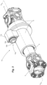
Figure 2 shows a perspective view of the propeller shaft according to one embodiment of the present invention; -
Figure 3 shows a side view in cross-section of the propeller shaft, as indicated by line A-A represented inFigure2 , according to the present invention, in the coupled state; -
Figure 4 shows a side view in cross-section of the propeller shaft, as indicated by line A-A represented inFigure 2 , according to the present invention, but in the decoupled state; and -
Figure 5 is a schematic view in exploded perspective of the propeller shaft, according to the present invention. - The invention is now described in relation to its particular embodiments with reference to the figures attached as examples of embodiments. These figures are schematic, and their dimensions and/or proportions may not correspond to reality, since they merely aim to describe the invention didactically. In addition, certain known and common constructive details may have been omitted for better clarity and concision of the description provided below. The reference numbers indicated in the figures are repeated along the different views to indicate equal or similar technical characteristics. In addition, the terms sometimes used here, such as: above, below, upper, lower, side, right, left, frontal, rear and their variants should be interpreted according to the guidance given in
Figure 1 . - Initially, for merely illustrative purposes, and particularly for the due contextualization and better understanding of the matter, according to the present invention,
Figure 1 schematically represents a vehicle (V) intended for the transportation of cargo or goods, such as a truck known to the state of the art. This vehicle (V), as schematically represented inFigure 1 , may be, for example, a model manufactured and marketed by CNH Industrial N. V. - Basically, it is possible to say that the vehicle (V) comprises a control and operation cab (C) under which are provided a transmission powertrain (M), such as a combustion engine associated with a gearbox, which are mounted on a chassis (E) supported by a front shaft (TD), a first rear shaft (T1) and a second rear shaft (T2). According to this description, these rear shafts (T1, T2) are pulled and, thus, will potentially be indicated as the first traction shaft (T1) and the second traction shaft (T2).
- From the drive assembly (M), which is formed of the gearbox within which are arranged a series of gears and other components responsible for transmitting the power generated in the engine and, from which extends a
first cardan shaft 1 to a first differential of the first traction shaft (T1) and, from the differential of the first traction shaft (T1), extends asecond cardan shaft 2 to the differential of the second traction shaft (T2). The power is generally divided equally between the first and second differentials to the wheels of the first (T1) and second (T2) traction shafts. Thus, the differentials transmit the power to the wheels of each shaft in a normal way using a crown/pinion system and epicycloidal gears, which is already well known to persons skilled in the art and, thus, will not be explored in this case. In addition, other details of the vehicle (V) are represented in a schematic way and do not require further explanation, since they are known in conventional cargo transport vehicles. - As mentioned above, it may be of interest, in certain applications, such as an unloaded vehicle (V), that power is not transmitted from the differential of the first traction shaft (T1) to the differential of the second traction shaft (T2), causing the vehicle (V) with 6x4 traction to take on a 6x2 traction configuration. With this 6x2 traction configuration, it is possible for the second traction shaft (T2) to be raised, generating fuel and tire savings. The raising of the second rear shaft can be done by normal means known to the state of the art, such as using components driven by the pneumatic system of the vehicle itself.
- The present invention aims, precisely, to allow for the coupling or decoupling, selectively and according to the interests of the driver, of the second differential from the second traction shaft (T2), transforming the traction configuration from 6x4 to a 6x2 traction configuration. Of course, in this more in-depth description of one embodiment of the invention, reference is made to a 6×4 and 6×2 traction configuration, but the invention can obviously be used in any traction configuration where one wishes to activate or deactivate a second traction shaft, such as a 4×4 / 4×2, 8×4 / 8×2 traction configuration, etc.
- With reference now to
Figure 2 , atransmission shaft 10 is shown, such as for coupling in a cardan shaft or replacing a conventional cardan shaft, which is specifically mounted between the first traction shaft (T1) and the second traction shaft (T2) of a vehicle (V). In this regard, theshaft 10 can be mounted between the differentials of two rear traction shafts of a vehicle comprising, for example, a 6×4 traction configuration, or even replace thesecond cardan shaft 2. - Since the first rear shaft (T1) and the second rear shaft (T2) can have different assembly heights or can also be mounted to the suspension of the vehicle, being subject to oscillations in height and, consequently, at a distance from each other,
crossheads shaft 10, which form the mechanical connection with the rest of the transmission powertrain of the vehicle. Furthermore, theshaft 10 comprises anassembly 5 of two concentric toothed shafts, which allow for the compensation of the distance that may exist between the first traction shaft (T1) and the second traction shaft (T2). - It is worth noting that both the
crossheads assembly 5, are mechanical constructions used in cardan shafts that are widely known and used in the state of the art, and can thus be replaced by any equivalent mechanical constructions, such as homokinetic joints or flanges associated with screws and nuts, in cases where the coupling is mounted on a long cardan shaft. The decision to choose crossheads, homokinetic joints or other mechanical construction elements does not alter the technical effects foreseen for the present invention. - In this regard, based on the scenario summarized above, it may be said that the present invention refers to a
new propeller shaft 10 comprising afirst shaft segment 12, which can be mounted on a power output, and asecond shaft segment 13, which can be mounted on a power input to receive the power coming from thefirst shaft segment 12. Bothshaft segments housing 11, so that thefirst shaft segment 12 can be rotated independently in relation to thesecond shaft segment 13, where thisfirst shaft segment 12 comprises, on the one hand, a power input and, on the other hand, is mounted concentrically with thesecond shaft segment 13. Thesecond shaft segment 13 also has, on one side, a toothed face (16) to receive a power input and, on the other side, it has a power output. Thus, the first 12 and second 13 shaft segments are coupled and decoupled selectively by means of aflange 15, which is mounted concentrically on the first shaft segment and comprises a toothed face for the respective coupling with the toothed face of the second shaft segment. Furthermore, thisflange 15 can move between a coupled and uncoupled position due to the coaxial displacement along the saidfirst shaft segment 12. - According to one embodiment of the present invention, the said
flange 15 is driven by acoupler 14 formed of anactuator 14a that possesses ashaft 18c equipped with a means ofreturn 20, and afork 17 connected to saidflange 15 provided with a groove in its internal diameter for connection with agrooved part 12a provided for in thefirst shaft segment 12, andteeth 15a on its lateral face to enable the connection with theteeth 16a arranged on thetoothed face 16 of thesecond shaft segment 13. - In these circumstances, it may be noted that the
propeller shaft 10, according to the present invention, can be installed in place of thesecond cardan shaft 2, between the first traction shaft (T1) and the second traction shaft (T2) of said vehicle (V). Thus, thefirst shaft segment 12 is mounted next at a power output deriving from thefirst cardan shaft 1, and thesecond shaft segment 13 is mounted on the power input, for example, on the differential of the second traction shaft (T2), saidshaft segments coupler 14 which is responsible for blocking and transmitting the power between theshaft segments - Also, in order to maintain the good functioning, and increase the service life, of said
propeller shaft 10, the object of the present invention, saidhousing 11 comprisessealant elements 8 to securely hold a lubricating and cooling fluid in contact with saidshaft segments actuator 14. - Of course, although it is mentioned here that the
first shaft segment 12 can be mounted on a power output and thesecond shaft segment 13 can be mounted on a power input, the configuration may be reversed, i.e., thefirst shaft segment 12 can be mounted on a power input and thesecond shaft segment 13 can be mounted on a power output without any prejudice or difference in relation to the technical effect achieved by the present invention. - According to one embodiment, said
toothed face 16 may be a fixed flange that is provided with a grooved surface on its inner diameter for connection with a respectivegrooved part 13a positioned at the end of thesecond shaft segment 13. In addition, as noted above, thetoothed face 16 or said fixed flange possessesteeth 16a on its lateral face to enable the connection with theteeth 15a arranged on the side face of themobile flange 15 of thefirst shaft segment 12. - According to one embodiment of the present invention, said
driver 14a can be of any model and use different appropriate means, such as, but not limited to, mechanical, magnetic, electrical or hydraulic means or a combination thereof, provided that it can enable the movement of saidfork 17 between at least two positions and, consequently, achieve coupling or decoupling between the said first andsecond shaft segments - According to one embodiment of the
coupler 14, in accordance with the present invention, saiddriver 14a comprises achamber 18 with airtight closure that is formed by a fixedcover 18a installed in abranch 11a of thehousing 11, and inside saidchamber 18 amobile piston 18b is positioned that is supported on theshaft 18c which supports theaforementioned fork 17 and the means ofreturn 20. - According to one embodiment of the present invention, the fixed
cover 18a of thedriver 14a is equipped with achannel 19a, that is fluidly connected to the hydraulic or pneumatic system of the vehicle (V) for feeding thechamber 18. Thus, on introducing compressed air or hydraulic fluid inside thechamber 18, this tends to expand its volume, shifting themobile piston 18b axially along theshaft 18c, towards the arrow "X", and, consequently, thefork 17, causing themobile flange 15 to move until it achieves the corresponding coupling with the fixedflange 16, thus transmitting power to thesecond shaft segment 13 and, consequently, to the second traction shaft (T2). Under these conditions, the driver is able to alter the configuration and traction of the vehicle from a configuration of 6×2 to 6×4 by simply activating and feeding saidchamber 18 of thedriver 14a. - Conversely, in order for the vehicle (V) to achieve a traction configuration of the 6×2 type, it is necessary for the pressure inside the
chamber 18 of thedriver 14a to be alleviated, allowing thefork 17 to shift themovable flange 15 in the direction of the arrow "Y", causing it to decouple from thetoothed face 16, interrupting the power transmission to the second traction shaft (T2) and thus allowing this second shaft to be raised. - Optionally, the fixed
cover 18a of thedriver 14a comprises acomplementary input 19b to allow for the installation of sensors, for example, a sensor for monitoring the pressure inside thechamber 18. - In accordance with the aforementioned embodiments, compressed air or hydraulic fluid is used. The use of these components as one of the ways to enable the displacement of the
fork 17 and, consequently, themobile flange 15, is appropriate since the lines of compressed air and, potentially, of hydraulic fluid already present in most commercial vehicles and machinery can be used. - Naturally, as highlighted above, although this description refers to the use of compressed air to vary the pressure inside the
chamber 18, other means can be provided, such as other fluids, like oil or water, or magnetic or even electromechanical means, such as solenoid valves. Furthermore, although it is noted that themobile flange 15 is in the disengaged position when the pressure inside thechamber 18 is approximately equal to the ambient pressure, it is clear that this embodiment can be reversed, so that theflange 15 is in the disengaged position only when the pressure inside thechamber 18 is increased, but this is less preferential, due to questions of operating safety. Nevertheless, although this specification refers to the terms "ambient pressure" and "increased pressure" with ambient pressure as a reference, it is clear that other pressure differentials that are not necessarily based on atmospheric pressure such as the base pressure can be used, including higher or even negative pressures, using a vacuum, provided that the pressure differential applied in thechamber 18 is sufficient to cause a shift of themobile flange 15 through an axial movement, as indicated above. - Additionally, it is important to highlight that, to ensure the return of the
fork 17 and, consequently, the decoupling of themobile flange 15, when there is a reduction of pressure in thechamber 18, and for the purpose of preventing the coupling medium from escaping from a coupled position to a decoupled position, the means ofreturn 20 may be a helical spring, ensuring that thecoupler 14 remains in a predetermined position, such as a decoupled standard position, as represented in the drawings, or, conversely, a coupled standard position. Obviously, the means of return can be suppressed if other forms of displacement of thefork 17 are used, such as magnetic or electromechanical means. Nevertheless, other means of return can also be provided, such as magnetic, mechanical or hydraulic means, etc. - Specifically, the coupling and decoupling of the
coupler 14 must be done with the vehicle stationary, that is, without thefirst shaft segment 12 rotating, however, though less advantageous, there is nothing to prevent such coupling and/or decoupling being done with the vehicle in motion. - Finally, and as observed above, the present invention also refers to a vehicle (V) for the transportation of cargo or goods, which comprises a control and operation cabin (C) and under which are provided a transmission powertrain (M), such as a combustion engine associated with a gearbox, which are mounted on a chassis (E), which is supported by a front shaft (TD), a first rear traction shaft (T1) and a second rear traction shaft (T2), connected by a
propeller shaft 10, like that observed above. - According to specific embodiments of the present invention, said vehicle (V) is a truck, such as those used in the road transportation of cargo or goods and, more particularly, which possesses the traction configuration of the 6×4 or 8×4 type, or the like.
- In the light of the above, it is important to clarify that this description is intended only to present and describe in exemplary form, specific embodiments of a propeller shaft for a vehicle, in accordance with the present invention. For these reasons, as persons skilled in the art should understand, various modifications and constructive combinations of equivalent elements are possible without, thus, departing from the scope of protection defined by the attached claims.
Claims (13)
- Propeller shaft for a vehicle, comprising:a first shaft segment (12);a second shaft segment (13);wherein said first and second shaft segments (12, 13) are mounted concentrically within a housing (11), the first shaft segment being able to rotate independently in relation to the second shaft segment,wherein the first shaft segment (12) possesses, on the one hand, a power input and, on the other hand, is mounted concentrically on the second shaft segment (13);the second shaft segment (13) comprising, on the one hand, a toothed face (16) to receive a power input and, on the other hand, having a power output,wherein said first and second shaft segments can be coupled or decoupled selectively by a flange (15),the flange (15) comprising a toothed face for coupling to the toothed face (16) of the second shaft segment (13) and being mounted concentrically on the first shaft segment (12);the flange (15) also being able to move between a coupled and a decoupled position due to coaxial displacement along said first shaft segment (12),the propeller shaft being characterized by further comprising, at its ends, crossheads (3, 4) for mechanical connection with the rest of the transmission powertrain of the vehicle (V), and also possessing an assembly (5) formed of toothed concentric shafts to compensate for the distance between a first traction shaft (T1) and a second traction shaft (T2) of the vehicle (V).
- Propeller shaft for a vehicle, according to claim 1, wherein that said flange (15) is activated using a coupler (14) formed of an actuator (14a) that possesses a shaft (18c) equipped with a means of return (20), and a fork (17) connected to said flange (15) that interacts with the toothed face (1) of said second shaft segment (13).
- Propeller shaft for a vehicle, according to claim 1, wherein said flange (15) comprises a groove in its internal diameter of connection with a grooved part (12A) provided in the first shaft segment (12), and teeth (15A) on its side face for connecting with the teeth (16a) positioned on the toothed face (16) of the second segment shaft (13).
- Propeller shaft for a vehicle, according to claim 1, wherein said first shaft segment (12) is mounted on a power output deriving from a first cardan shaft (1), and the second shaft segment (13) is mounted on a power input of a differential of the second traction shaft (T2).
- Propeller shaft for a vehicle, according to claim 1, wherein said housing (11) comprises sealant elements (8) for holding a lubricating and cooling fluid in contact with said shaft segments (12, 13) and the coupler (14).
- Propeller shaft for a vehicle, according to claim 1, wherein said toothed face (16) is foreseen in a fixed flange provided with a grooved surface in its internal diameter of connection with a corresponding grooved part (13a) positioned at the end of said second shaft segment (13).
- Propeller shaft for a vehicle, according to claim 2, wherein the said actuator (14a) is of the mechanical, magnetic, electrical or hydraulic type or a combination thereof.
- Propeller shaft for a vehicle, in accordance with claim 2, wherein said actuator (14a) comprises a chamber (18) with an airtight closure formed by a fixed cover (18a) installed in a branch (11a) of said housing (11), and inside said chamber (18) a mobile piston (18b) is positioned that is supported by a shaft (18c) that supports said fork (17) and the means of return (20).
- Propeller shaft for a vehicle, according to claim 8, wherein said fixed cover (18a) is equipped with a channel (19a) that is directly connected to the hydraulic or pneumatic system of the vehicle (V).
- Propeller shaft for a vehicle, according to claim 8, wherein said fixed cover (18a) comprises a complementary input (19b) for the installation of sensors, such as a pressure monitoring sensor.
- Propeller shaft for a vehicle, according to claim 2, wherein said means of return (20) is a helical spring.
- Vehicle, comprising a control and operation cabin (C) and under which a transmission powertrain (M) is provided, such as a combustion engine associated with a gearbox, which are mounted on a chassis (E) that is supported by a front shaft (TD), a first rear traction shaft (T1) and a second rear traction shaft (T2), characterized by the fact that the first rear traction shaft (T1) and the second rear traction shaft (T2) are connected by means of a propeller shaft (10) according to any of the previous claims.
- Vehicle, according to claim 12, wherein said vehicle is intended for the transportation of cargo and goods and has a 6×4 or 8×4 traction configuration.
Applications Claiming Priority (2)
| Application Number | Priority Date | Filing Date | Title |
|---|---|---|---|
| BR102018071263-2A BR102018071263B1 (en) | 2018-10-16 | POWER TRANSMISSION SHAFT FOR VEHICLE AND VEHICLE | |
| PCT/BR2019/050413 WO2020077425A1 (en) | 2018-10-16 | 2019-09-20 | Power-transmission axle for vehicle and vehicle |
Publications (3)
| Publication Number | Publication Date |
|---|---|
| EP3868593A1 EP3868593A1 (en) | 2021-08-25 |
| EP3868593A4 EP3868593A4 (en) | 2022-08-10 |
| EP3868593B1 true EP3868593B1 (en) | 2025-01-01 |
Family
ID=70282907
Family Applications (1)
| Application Number | Title | Priority Date | Filing Date |
|---|---|---|---|
| EP19873723.1A Active EP3868593B1 (en) | 2018-10-16 | 2019-09-20 | Power-transmission axle for vehicle and vehicle |
Country Status (2)
| Country | Link |
|---|---|
| EP (1) | EP3868593B1 (en) |
| WO (1) | WO2020077425A1 (en) |
Family Cites Families (10)
| Publication number | Priority date | Publication date | Assignee | Title |
|---|---|---|---|---|
| GB736884A (en) * | 1952-03-06 | 1955-09-14 | Arnaud Labeguerie | Improvements in motor vehicles having two rear driving axles |
| JP5257482B2 (en) | 2011-04-13 | 2013-08-07 | トヨタ自動車株式会社 | Power transmission device for four-wheel drive vehicles |
| CN103596794B (en) * | 2011-04-20 | 2017-08-25 | Gkn 动力传动系统有限责任公司 | Power transmission unit |
| US8651994B2 (en) * | 2011-09-30 | 2014-02-18 | Arvinmeritor Technology, Llc | Drive axle assembly and disengagement system |
| US8911321B2 (en) * | 2012-08-23 | 2014-12-16 | Dana Heavy Vehicle Systems Group, Llc | Tandem axle system |
| EP2928718B1 (en) * | 2012-12-05 | 2020-08-19 | Mack Trucks, Inc. | Vehicle with multiple drive axle assembly with a raisable and lowerable rear drive axle, and method of neutralizing the rear drive axle and operating such a vehicle |
| WO2015080722A1 (en) * | 2013-11-27 | 2015-06-04 | Volvo Truck Corporation | Vehicle with rear drive axle assembly and the ability to neutralize |
| WO2016205480A1 (en) * | 2015-06-16 | 2016-12-22 | Dana Heavy Vehicle Systems Group, Llc | Disconnectable 6x4 tandem axle and method of operation |
| BR102015018592A2 (en) * | 2015-08-03 | 2017-02-07 | Cnh Ind Latin America Ltda | axle and vehicle coupling |
| SE540826C2 (en) * | 2016-04-29 | 2018-11-20 | Scania Cv Ab | An axle gear system, a driving axle system and a motor vehicle |
-
2019
- 2019-09-20 EP EP19873723.1A patent/EP3868593B1/en active Active
- 2019-09-20 WO PCT/BR2019/050413 patent/WO2020077425A1/en not_active Ceased
Also Published As
| Publication number | Publication date |
|---|---|
| EP3868593A1 (en) | 2021-08-25 |
| WO2020077425A1 (en) | 2020-04-23 |
| BR102018071263A2 (en) | 2020-04-28 |
| EP3868593A4 (en) | 2022-08-10 |
Similar Documents
| Publication | Publication Date | Title |
|---|---|---|
| US10378634B2 (en) | Axle assembly having a clutch collar actuator mechanism | |
| US9784355B1 (en) | Axle disconnect and differential lock combination | |
| EP3385106B1 (en) | Axle assembly having multiple clutch collars | |
| EP2574490B1 (en) | Drive axle assembly and disengagement system | |
| EP3333001B1 (en) | Shaft connection for a vehicle | |
| US10197144B2 (en) | Drive unit with torque vectoring and an axle disconnect and reconnect mechanism | |
| US5098351A (en) | Torque distribution control system for a four-wheel drive motor vehicle | |
| US7448977B2 (en) | Motor vehicle transaxle having a differential mechanism controlled by an on-demand clutch | |
| US20050261101A1 (en) | Torque coupling differential assembly with torque disconnect | |
| US10233976B2 (en) | Vehicle drivetrain assembly having a clutch collar actuator mechanism | |
| CN115867736B (en) | Hubs for mounting wheels on axles of work vehicles | |
| KR102617112B1 (en) | Electro-hydraulic limited slip differential system | |
| EP3868593B1 (en) | Power-transmission axle for vehicle and vehicle | |
| CN114728545B (en) | Hub for mounting wheels on axles of work vehicles | |
| US9849778B2 (en) | Multi-speed transfer case | |
| EP2302246B1 (en) | A rotary transmission coupling | |
| BR102018071263B1 (en) | POWER TRANSMISSION SHAFT FOR VEHICLE AND VEHICLE | |
| JPH07137551A (en) | Differential gear mechanism |
Legal Events
| Date | Code | Title | Description |
|---|---|---|---|
| STAA | Information on the status of an ep patent application or granted ep patent |
Free format text: STATUS: THE INTERNATIONAL PUBLICATION HAS BEEN MADE |
|
| PUAI | Public reference made under article 153(3) epc to a published international application that has entered the european phase |
Free format text: ORIGINAL CODE: 0009012 |
|
| STAA | Information on the status of an ep patent application or granted ep patent |
Free format text: STATUS: REQUEST FOR EXAMINATION WAS MADE |
|
| 17P | Request for examination filed |
Effective date: 20210514 |
|
| AK | Designated contracting states |
Kind code of ref document: A1 Designated state(s): AL AT BE BG CH CY CZ DE DK EE ES FI FR GB GR HR HU IE IS IT LI LT LU LV MC MK MT NL NO PL PT RO RS SE SI SK SM TR |
|
| DAV | Request for validation of the european patent (deleted) | ||
| DAX | Request for extension of the european patent (deleted) | ||
| A4 | Supplementary search report drawn up and despatched |
Effective date: 20220712 |
|
| RIC1 | Information provided on ipc code assigned before grant |
Ipc: B60B 35/14 20060101ALI20220707BHEP Ipc: B60B 35/12 20060101ALI20220707BHEP Ipc: B60K 17/02 20060101ALI20220707BHEP Ipc: B60K 17/36 20060101ALI20220707BHEP Ipc: B60K 17/35 20060101ALI20220707BHEP Ipc: B60K 17/22 20060101ALI20220707BHEP Ipc: B60K 23/08 20060101AFI20220707BHEP |
|
| GRAP | Despatch of communication of intention to grant a patent |
Free format text: ORIGINAL CODE: EPIDOSNIGR1 |
|
| STAA | Information on the status of an ep patent application or granted ep patent |
Free format text: STATUS: GRANT OF PATENT IS INTENDED |
|
| INTG | Intention to grant announced |
Effective date: 20240729 |
|
| P01 | Opt-out of the competence of the unified patent court (upc) registered |
Free format text: CASE NUMBER: APP_49353/2024 Effective date: 20240830 |
|
| GRAS | Grant fee paid |
Free format text: ORIGINAL CODE: EPIDOSNIGR3 |
|
| GRAA | (expected) grant |
Free format text: ORIGINAL CODE: 0009210 |
|
| STAA | Information on the status of an ep patent application or granted ep patent |
Free format text: STATUS: THE PATENT HAS BEEN GRANTED |
|
| AK | Designated contracting states |
Kind code of ref document: B1 Designated state(s): AL AT BE BG CH CY CZ DE DK EE ES FI FR GB GR HR HU IE IS IT LI LT LU LV MC MK MT NL NO PL PT RO RS SE SI SK SM TR |
|
| REG | Reference to a national code |
Ref country code: GB Ref legal event code: FG4D |
|
| REG | Reference to a national code |
Ref country code: CH Ref legal event code: EP |
|
| REG | Reference to a national code |
Ref country code: DE Ref legal event code: R096 Ref document number: 602019064404 Country of ref document: DE |
|
| REG | Reference to a national code |
Ref country code: IE Ref legal event code: FG4D |
|
| REG | Reference to a national code |
Ref country code: LT Ref legal event code: MG9D |
|
| REG | Reference to a national code |
Ref country code: NL Ref legal event code: MP Effective date: 20250101 |
|
| REG | Reference to a national code |
Ref country code: AT Ref legal event code: MK05 Ref document number: 1755914 Country of ref document: AT Kind code of ref document: T Effective date: 20250101 |
|
| PG25 | Lapsed in a contracting state [announced via postgrant information from national office to epo] |
Ref country code: NL Free format text: LAPSE BECAUSE OF FAILURE TO SUBMIT A TRANSLATION OF THE DESCRIPTION OR TO PAY THE FEE WITHIN THE PRESCRIBED TIME-LIMIT Effective date: 20250101 |
|
| PG25 | Lapsed in a contracting state [announced via postgrant information from national office to epo] |
Ref country code: FI Free format text: LAPSE BECAUSE OF FAILURE TO SUBMIT A TRANSLATION OF THE DESCRIPTION OR TO PAY THE FEE WITHIN THE PRESCRIBED TIME-LIMIT Effective date: 20250101 |
|
| PG25 | Lapsed in a contracting state [announced via postgrant information from national office to epo] |
Ref country code: PL Free format text: LAPSE BECAUSE OF FAILURE TO SUBMIT A TRANSLATION OF THE DESCRIPTION OR TO PAY THE FEE WITHIN THE PRESCRIBED TIME-LIMIT Effective date: 20250101 |
|
| PG25 | Lapsed in a contracting state [announced via postgrant information from national office to epo] |
Ref country code: ES Free format text: LAPSE BECAUSE OF FAILURE TO SUBMIT A TRANSLATION OF THE DESCRIPTION OR TO PAY THE FEE WITHIN THE PRESCRIBED TIME-LIMIT Effective date: 20250101 |
|
| PG25 | Lapsed in a contracting state [announced via postgrant information from national office to epo] |
Ref country code: NO Free format text: LAPSE BECAUSE OF FAILURE TO SUBMIT A TRANSLATION OF THE DESCRIPTION OR TO PAY THE FEE WITHIN THE PRESCRIBED TIME-LIMIT Effective date: 20250401 Ref country code: IS Free format text: LAPSE BECAUSE OF FAILURE TO SUBMIT A TRANSLATION OF THE DESCRIPTION OR TO PAY THE FEE WITHIN THE PRESCRIBED TIME-LIMIT Effective date: 20250501 |
|
| PG25 | Lapsed in a contracting state [announced via postgrant information from national office to epo] |
Ref country code: HR Free format text: LAPSE BECAUSE OF FAILURE TO SUBMIT A TRANSLATION OF THE DESCRIPTION OR TO PAY THE FEE WITHIN THE PRESCRIBED TIME-LIMIT Effective date: 20250101 |
|
| PG25 | Lapsed in a contracting state [announced via postgrant information from national office to epo] |
Ref country code: LV Free format text: LAPSE BECAUSE OF FAILURE TO SUBMIT A TRANSLATION OF THE DESCRIPTION OR TO PAY THE FEE WITHIN THE PRESCRIBED TIME-LIMIT Effective date: 20250101 Ref country code: PT Free format text: LAPSE BECAUSE OF FAILURE TO SUBMIT A TRANSLATION OF THE DESCRIPTION OR TO PAY THE FEE WITHIN THE PRESCRIBED TIME-LIMIT Effective date: 20250502 |
|
| PG25 | Lapsed in a contracting state [announced via postgrant information from national office to epo] |
Ref country code: GR Free format text: LAPSE BECAUSE OF FAILURE TO SUBMIT A TRANSLATION OF THE DESCRIPTION OR TO PAY THE FEE WITHIN THE PRESCRIBED TIME-LIMIT Effective date: 20250402 Ref country code: BG Free format text: LAPSE BECAUSE OF FAILURE TO SUBMIT A TRANSLATION OF THE DESCRIPTION OR TO PAY THE FEE WITHIN THE PRESCRIBED TIME-LIMIT Effective date: 20250101 |
|
| PG25 | Lapsed in a contracting state [announced via postgrant information from national office to epo] |
Ref country code: AT Free format text: LAPSE BECAUSE OF FAILURE TO SUBMIT A TRANSLATION OF THE DESCRIPTION OR TO PAY THE FEE WITHIN THE PRESCRIBED TIME-LIMIT Effective date: 20250101 |
|
| PG25 | Lapsed in a contracting state [announced via postgrant information from national office to epo] |
Ref country code: CZ Free format text: LAPSE BECAUSE OF FAILURE TO SUBMIT A TRANSLATION OF THE DESCRIPTION OR TO PAY THE FEE WITHIN THE PRESCRIBED TIME-LIMIT Effective date: 20250101 |
|
| PG25 | Lapsed in a contracting state [announced via postgrant information from national office to epo] |
Ref country code: SE Free format text: LAPSE BECAUSE OF FAILURE TO SUBMIT A TRANSLATION OF THE DESCRIPTION OR TO PAY THE FEE WITHIN THE PRESCRIBED TIME-LIMIT Effective date: 20250101 |
|
| REG | Reference to a national code |
Ref country code: DE Ref legal event code: R097 Ref document number: 602019064404 Country of ref document: DE |
|
| PG25 | Lapsed in a contracting state [announced via postgrant information from national office to epo] |
Ref country code: SM Free format text: LAPSE BECAUSE OF FAILURE TO SUBMIT A TRANSLATION OF THE DESCRIPTION OR TO PAY THE FEE WITHIN THE PRESCRIBED TIME-LIMIT Effective date: 20250101 |
|
| PG25 | Lapsed in a contracting state [announced via postgrant information from national office to epo] |
Ref country code: DK Free format text: LAPSE BECAUSE OF FAILURE TO SUBMIT A TRANSLATION OF THE DESCRIPTION OR TO PAY THE FEE WITHIN THE PRESCRIBED TIME-LIMIT Effective date: 20250101 |
|
| PGFP | Annual fee paid to national office [announced via postgrant information from national office to epo] |
Ref country code: DE Payment date: 20250926 Year of fee payment: 7 |
|
| PGFP | Annual fee paid to national office [announced via postgrant information from national office to epo] |
Ref country code: IT Payment date: 20250909 Year of fee payment: 7 |
|
| PGFP | Annual fee paid to national office [announced via postgrant information from national office to epo] |
Ref country code: FR Payment date: 20250925 Year of fee payment: 7 |
|
| PG25 | Lapsed in a contracting state [announced via postgrant information from national office to epo] |
Ref country code: EE Free format text: LAPSE BECAUSE OF FAILURE TO SUBMIT A TRANSLATION OF THE DESCRIPTION OR TO PAY THE FEE WITHIN THE PRESCRIBED TIME-LIMIT Effective date: 20250101 |
|
| PG25 | Lapsed in a contracting state [announced via postgrant information from national office to epo] |
Ref country code: RO Free format text: LAPSE BECAUSE OF FAILURE TO SUBMIT A TRANSLATION OF THE DESCRIPTION OR TO PAY THE FEE WITHIN THE PRESCRIBED TIME-LIMIT Effective date: 20250101 |
|
| PG25 | Lapsed in a contracting state [announced via postgrant information from national office to epo] |
Ref country code: SK Free format text: LAPSE BECAUSE OF FAILURE TO SUBMIT A TRANSLATION OF THE DESCRIPTION OR TO PAY THE FEE WITHIN THE PRESCRIBED TIME-LIMIT Effective date: 20250101 |
|
| PLBE | No opposition filed within time limit |
Free format text: ORIGINAL CODE: 0009261 |
|
| STAA | Information on the status of an ep patent application or granted ep patent |
Free format text: STATUS: NO OPPOSITION FILED WITHIN TIME LIMIT |
|
| 26N | No opposition filed |
Effective date: 20251002 |