EP3868561A1 - Liquid ejection head and liquid ejection apparatus - Google Patents
Liquid ejection head and liquid ejection apparatus Download PDFInfo
- Publication number
- EP3868561A1 EP3868561A1 EP21151228.0A EP21151228A EP3868561A1 EP 3868561 A1 EP3868561 A1 EP 3868561A1 EP 21151228 A EP21151228 A EP 21151228A EP 3868561 A1 EP3868561 A1 EP 3868561A1
- Authority
- EP
- European Patent Office
- Prior art keywords
- liquid ejection
- flow path
- ink
- temperature control
- base portion
- Prior art date
- Legal status (The legal status is an assumption and is not a legal conclusion. Google has not performed a legal analysis and makes no representation as to the accuracy of the status listed.)
- Granted
Links
Images



Classifications
-
- B—PERFORMING OPERATIONS; TRANSPORTING
- B41—PRINTING; LINING MACHINES; TYPEWRITERS; STAMPS
- B41J—TYPEWRITERS; SELECTIVE PRINTING MECHANISMS, i.e. MECHANISMS PRINTING OTHERWISE THAN FROM A FORME; CORRECTION OF TYPOGRAPHICAL ERRORS
- B41J2/00—Typewriters or selective printing mechanisms characterised by the printing or marking process for which they are designed
- B41J2/005—Typewriters or selective printing mechanisms characterised by the printing or marking process for which they are designed characterised by bringing liquid or particles selectively into contact with a printing material
- B41J2/01—Ink jet
- B41J2/135—Nozzles
- B41J2/14—Structure thereof only for on-demand ink jet heads
-
- B—PERFORMING OPERATIONS; TRANSPORTING
- B41—PRINTING; LINING MACHINES; TYPEWRITERS; STAMPS
- B41J—TYPEWRITERS; SELECTIVE PRINTING MECHANISMS, i.e. MECHANISMS PRINTING OTHERWISE THAN FROM A FORME; CORRECTION OF TYPOGRAPHICAL ERRORS
- B41J2202/00—Embodiments of or processes related to ink-jet or thermal heads
- B41J2202/01—Embodiments of or processes related to ink-jet heads
- B41J2202/08—Embodiments of or processes related to ink-jet heads dealing with thermal variations, e.g. cooling
Definitions
- Embodiments described herein relate generally to a liquid ejection head and a liquid ejection apparatus.
- a liquid ejection head used in various liquid ejection apparatuses is known to have a configuration in which, for example, a liquid ejection unit including an actuator for ejecting liquid, an inflow path connected to a primary side of the liquid ejection unit, and an outflow path connected to a secondary side of the liquid ejection unit are included.
- a liquid ejection head in order to reduce a temperature difference of ink in the liquid ejection head and improve printing performance, a substrate including a flow path through which hot water flows may be provided.
- Embodiments provide a liquid ejection head and a liquid ejection apparatus that are small and have high printing performance.
- a liquid ejection head including a liquid ejection unit configured to eject liquid, an ink flow path connected to the liquid ejection unit and through which ink supplied to the liquid ejection unit passes, and a base portion where a temperature control flow path through which a fluid for temperature control passes is formed.
- the liquid ejection unit is configured to include an actuator including a plurality of pressure chambers communicating with a plurality of nozzles for ejecting liquid and a common liquid chamber communicating with the plurality of pressure chambers
- the base portion is configured to include a pair of base plates that are assembled facing each other, and the ink flow path and the temperature control flow path are formed by grooves formed on at least one of facing surfaces of the pair of the base plates.
- the liquid ejection unit is configured to include a pair of the actuators
- the base portion is configured to include a plurality of the ink flow paths communicating with the common liquid chamber of a plurality of the actuators, and the temperature control flow path.
- the base portion is configured to include a pair of the ink flow paths respectively connected to the pair of the actuators, ports on a primary side and a secondary side of the ink flow path connected to one of the actuators are arranged on one main surface side of the base portion, ports on the primary side and the secondary side of the ink flow path connected to the other of the actuators are arranged on the other main surface side of the base portion, and a port on a primary side and a port on a secondary side of the temperature control flow path are arranged on one main surface side and the other main surface side of the base portion, respectively.
- a liquid ejection apparatus comprising: the liquid ejection head as described above; and a moving device configured to move a recording medium relative to the liquid ejection head.
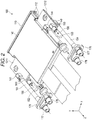
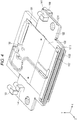
- FIGS. 1 and 2 are perspective views illustrating the configuration of the liquid ejection head 100 according to the first embodiment.
- FIG. 3 is a cross-sectional view of the liquid ejection head 100.
- FIG. 4 is a perspective view illustrating a partial configuration of the liquid ejection head 100.
- FIG. 5 is a perspective view illustrating a part of the liquid ejection head 100 in an exploded manner.
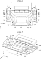
- FIG. 6 is a plan view of a base portion
- FIG. 7 is a perspective view of a base plate 1212.
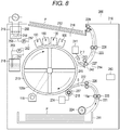
- FIG. 8 is an explanatory diagram illustrating a configuration of the liquid ejection apparatus using the liquid ejection head 100.
- arrows X, Y, and Z indicate three directions orthogonal to each other.
- the X-axis is along a first direction, which is an arrangement direction of nozzles
- the Y-axis is along a second direction, which is an arrangement direction of nozzle rows
- the Z-axis is along a third direction, which is the direction in which liquid droplets are ejected.
- the configuration is illustrated enlarged, reduced or omitted in each figure as appropriate.
- the liquid ejection head 100 includes a liquid ejection unit 110, a base portion 120, a plurality of circuit board units 130, a cover 140, and a pair of ink supply pipes 151 and 154, a pair of ink recovery pipes 153 and 152, a temperature control supply pipe 155, and a temperature control recovery pipe 156.
- the liquid ejection head 100 is a two-color head including ink flow paths of two systems and a drive system and ejecting two different types of ink. When the same ink is used for the two systems, the liquid ejection head 100 becomes a single color head with doubled resolution.
- the liquid ejection head 100 is provided in a liquid ejection apparatus 200 such as an ink jet recording apparatus illustrated in FIG. 8 , for example.
- the liquid ejection head 100 is provided in a circulation type ink circuit in which ink flow paths are respectively connected to a pair of ink tanks 251 as liquid accommodating portions provided in the liquid ejection apparatus 200 and ink is circulated to and from the ink tanks 251.
- the liquid ejection head 100 is disposed, for example, in a posture in which nozzles 114 of the liquid ejection unit 110 are directed downward. As the liquid ejection head 100, a common liquid chamber circulation type head will be illustrated.
- the liquid ejection unit 110 includes a nozzle plate 111 and a pair of actuators 1121 and 1122.
- the nozzle plate 111 is configured in a plate shape and includes a plurality of nozzles 114 aligned in the first direction.
- the nozzle plate 111 includes one or more rows of nozzles, for example, the same number as the actuators 1121 and 1122, in which a plurality of nozzles 114 are arranged in the first direction. In the present embodiment, two rows of nozzles are arranged in two colors, one row for each flow path.
- Each nozzle 114 is a through-hole that penetrates the nozzle plate 111.
- An axial direction of the nozzle 114 is along the third direction.
- the actuators 1121 and 1122 are provided on one side and the other side in the second direction along the thickness direction of the base portion 120 at the end portions of the base portion 120 on the nozzle plate 111 side, respectively.
- Each of the actuators 1121 and 1122 includes a plurality of pressure chambers aligned in the first direction and a common liquid chamber 115 communicating with the plurality of pressure chambers.
- the common liquid chamber 115 extends in the first direction and configures a path for allowing ink to flow from one side to the other side or from the other side to one side of each of the actuators 1121 and 1122 in the first direction.
- the actuators 1121 and 1122 include a plurality of drive element portions for driving each pressure chamber in the first direction.
- the first actuator 1121 configures a path for allowing ink to flow from one side to the other side
- the other actuator 1122 configures a path for allowing ink to flow from the other side to one side.
- the plurality of pressure chambers of the actuators 1121 and 1122 respectively communicate with the nozzles 114 of the nozzle plate 111 disposed to face the actuators 1121 and 1122.
- An electrode is formed in each pressure chamber.
- the electrode is electrically connected to a drive IC 133 via a wiring formed on a circuit board 131 and a flexible wiring board 132 of the circuit board unit 130.
- the base portion 120 is configured by assembling a pair of base plates 1211 and 1212 made of a ceramic material in a plate shape by bonding.
- a first ink supply flow path 122, a first ink recovery flow path 123, a second ink supply flow path 124, a second ink recovery flow path 125, and a temperature control flow path 126 are formed in the base portion 120 by grooves formed in predetermined regions on facing surfaces of the pair of base plates 1211 and 1212.
- a first supply opening 161, a first recovery opening 162, a first introduction port 142, a first discharge port 143, and a temperature control recovery opening 166 are formed on one base plate 1211.
- the first supply opening 161, the first recovery opening 162, the first introduction port 142, the first discharge port 143, and the temperature control recovery opening 166 are openings that penetrate the base plate 1211 in the second direction, which is the thickness direction.
- the first supply opening 161, the first recovery opening 162, and the temperature control recovery opening 166 bring the first ink supply flow path 122, the first ink recovery flow path 123, and the temperature control flow path 126 into communication with ports 141, 144, and 150 provided on the main surface on one side of the base plate 1211, respectively.
- the first introduction port 142 and the first discharge port 143 bring the first ink supply flow path 122 and the first ink recovery flow path 123 into communication with the common liquid chamber 115 of the first actuator 1121 provided on one main surface of the base plate 1211.
- a second supply opening 164, a second recovery opening 163, a second introduction port 147, a second discharge port 146, and a temperature control supply opening 165 are formed on the other base plate 1212.
- the second supply opening 164, the second recovery opening 163, the second introduction port 147, the second discharge port 146, and the temperature control supply opening 165 are openings that penetrate the base plate 1212 in the second direction, which is the thickness direction.
- the second ink supply port 164, the second ink recovery port 163, and the temperature control supply opening 165 bring the second ink supply flow path 124, the second ink recovery flow path 125, and the temperature control flow path 126 into communication with ports 148, 144, and 149 provided on the main surface on the other side of the base plate 1212 respectively.
- the second introduction port 147 and the second discharge port 146 bring the second supply flow path 124 and the second ink recovery flow path 125 into communication with the common liquid chamber 115 of the second actuator 1121 provided on the other main surface of the base plate 1212.
- the openings are configured in a predetermined position and shape so that a flow path resistance and flow path length of each flow path become predetermined values.
- the first ink supply flow path 122 is formed from the first supply opening 161 communicating with the first supply port 141 provided on the main surface on one side of the base portion 120 to the first introduction port 142 communicating with the primary side of the common liquid chamber 115 of one actuator 1121.
- the first ink recovery flow path 123 is formed from the first discharge port 143 communicating with the secondary side of the common liquid chamber 115 of one actuator 1121 to the first recovery opening 162 communicating with the first recovery port 144 provided on the main surface on one side of the base portion 120.
- the second ink supply flow path 124 is formed from the second supply opening 164 communicating with the second supply port 148 provided on the main surface on the other side of the base portion 120 to the second introduction port 147 communicating with the primary side of the common liquid chamber 115 of the other actuator 1122.
- the second ink recovery flow path 125 is formed from the second discharge port 146 communicating with the secondary side of the common liquid chamber 115 of the other actuator 1122 to the second recovery opening 163 communicating with the second recovery port 145 provided on the main surface on the other side of the base portion 120.
- the temperature control flow path 126 is formed from the temperature control supply opening 165 that communicates with the temperature control supply port 149 arranged on one end side of the base portion 120 in the first direction to the temperature control recovery opening 166 that communicates with the temperature control recovery port 150 arranged on the other end side of the first direction of the base portion 120 through a target region where the drive IC is arranged and a region adjacent to the common liquid chamber 115 of each of the actuators 1121 and 1122.
- the temperature control flow path 126 partially branches to pass through the respective regions.
- Flow paths of three systems of the first ink flow path 128 configured with the first ink supply flow path 122 and the first ink recovery flow path 123, the second ink flow path 129 configured with the second ink supply flow path 124 and the second ink recovery flow path 125, and the temperature control flow path 126 are provided in the same base portion 120. That is, the flow paths are formed by the grooves formed on the facing surfaces of the pair of base plates 1211 and 1212, most of the flow paths are formed at the same position in the second direction along the thickness direction of the base portion 120. That is, the pair of ink flow paths 128 and 129 and the temperature control flow path 126 include a flow path portion configured by the grooves formed on the same surface.
- the temperature control flow path 126 includes a main flow path portion 127 arranged at the center of the base portion 120 in the first direction.
- the main flow path portion 127 is arranged in a region where heat generating components such as the drive IC are arranged and a region where the actuators 1121 and 1122 are arranged.
- the second ink recovery flow path 125 is fluidly and independently arranged adjacent to one side of the main flow path portion 127 of the temperature control flow path 126 in the first direction, and further, the first ink supply flow path 122 is fluidly and independently arranged adjacent to one side of the second ink recovery flow path 125 in the first direction.
- the first ink recovery flow path 123 is fluidly and independently arranged adjacent to the other side of the main flow path portion 127 of the temperature control flow path 126 in the first direction, and further, the second ink supply flow path 124 is fluidly and independently arranged adjacent to the other side of the first ink recovery flow path 123 in the first direction.
- the primary side and secondary side end portions of the first ink flow path 128 are guided to the main surface on one side of the base portion 120, and are connected to the first supply port 141 and the first recovery port 144 arranged on the main surface on one side, respectively.
- the first supply port 141 and the first recovery port 144 are respectively connected to the ink supply pipe 151 and the ink recovery pipe 153, and are connected to the ink tank 251 via a connection flow path 253 configured with the ink supply pipe 151, the ink recovery pipe 153, and a connection pipe such as other pipe-shaped members.
- the primary side and secondary side end portions of the second ink flow path 129 are guided to the main surface on other side of the base portion 120, and are connected to the second supply port 148 and the second recovery port 145 provided on the other main surface side, respectively.
- the second supply port 148 and the second recovery port 145 are respectively connected to the ink supply pipe 154 and the ink recovery pipe 152, and are connected to another ink tank 251 via the connection flow path 253 configured with the ink supply pipe 154, the ink recovery pipe 152, and a connection pipe such as other pipe-shaped members.
- the temperature control flow path 126 branches from the temperature control supply port 149 provided on the other main surface side of the base portion 120, which is one end side in the first direction, into two flow paths, flows from one side to the other side in the first direction through the target portion where the actuators 1121 and 1122 are arranged, merges, and reaches the temperature control recovery port 150 provided on one main surface side of the base portion 120, which is the other end side in the first direction.
- the primary side end portion of the temperature control channel 126 is connected to the temperature control supply port 149 arranged on the other main surface side of the base portion 120, and the secondary side end portion of the temperature control channel 126 is connected to the temperature control recovery port 150 arranged on one main surface side of the base portion 120.
- the temperature control supply port 149 and the temperature control recovery port 150 are connected to the temperature control supply pipe 155 and the temperature control recovery pipe 156, respectively, and are connected to a hot water tank 255 via a connection flow path 258 configured with the temperature control supply pipe 155, the temperature control recovery pipe 156 and other connecting pipes such as pipe-shaped members.
- the circuit board units 130 are provided on both sides of the base portion 120 to sandwich the base portion 120 in the second direction.
- One pair of circuit board units 130 includes a circuit board 131, flexible wiring boards 132, and the drive IC 133.
- Various electronic components and connectors are mounted on the circuit.
- a plurality of flexible wiring boards 132 are disposed in parallel in the first direction.
- the drive IC 133 is mounted on the plurality of flexible wiring boards 132.
- One end side of the flexible wiring board 132 in the third direction is connected to the circuit board 131, and the other end side is connected to the actuators 1121 and 1122.
- the circuit board unit 130 is arranged in the central portion of the base portion 120 in the first direction.
- a part of the base portion 120 extends outward in the first direction of the circuit board unit 130, and the ports 141, 144, 145, 148, 149, and 150 and the pipes 151 to 156 are arranged outside the circuit board unit 130 in the first direction.
- the drive IC 133 is electrically connected to the electrode formed in the pressure chamber via the wiring on the circuit board 131, via the flexible wiring board 132.
- the liquid ejection head 100 configured as described above applies a drive voltage to the electrodes of the actuators 1121 and 1122 by the drive IC to increase or decrease the volume of the pressure chamber to eject liquid droplets from the nozzles 114 facing the pressure chamber.
- ink flows from the plurality of ink tanks 251 to pass through the first ink supply flow path 122 and the second ink supply flow path 124 of the base portion 120, respectively, through the pair of supply pipes 151 and 154, and reaches the plurality of pressure chambers from the common liquid chamber 115 of the pair of actuators.
- the ink is ejected from the nozzles 114 of the nozzle row disposed to face the pressure chamber.
- the ink is recovered again in the ink tank 251 by being flowed from the pressure chamber and passed through the common liquid chamber 115 and the first ink recovery flow path 123 and the second ink recovery flow path 125 of the base portion 120 through the pair of recovery pipes 153 and 152, and circulates.
- the supply pipes 151 and 154 are provided with filters 176.
- the filter 176 includes a supply port portion 177 and an outlet portion 178 for removing air bubbles.
- hot water or cold water passes through the temperature control flow path 126 to exchange heat with the members surrounding the temperature control flow path 126 in order to make the temperature of the liquid discharge head 100 uniform.
- FIG. 8 is an explanatory diagram illustrating the configuration of an ink jet printer as the liquid ejection apparatus 200.
- the liquid ejection apparatus 200 is an apparatus that performs various processing such as image formation while conveying, for example, paper P which is a recording medium.
- the liquid ejection apparatus 200 includes a casing 210 configuring an outer shell, a paper feed cassette 211 as a paper supply unit, a paper discharge tray 212 as a discharge unit, a holding roller 213 as a moving device that moves paper P relative to the liquid ejection head 100 by rotating while holding the paper P on the outer surface thereof, a conveyance device 214, a holding device 215, an image forming device 216, a discharging and peeling device 217, a plurality of liquid supply devices 218, and a plurality of temperature control devices 219.
- FIG. 8 only one of the plurality of liquid supply devices 218 and one of the plurality of temperature control devices 219 is illustrated.
- the paper feed cassette 211 is provided inside the casing 210, and the paper discharge tray 212 holding the paper P as a recording medium is provided at the upper part of the casing 210.
- the paper discharge tray 212 supports the paper P discharged to the outside of the casing 210 by the conveyance device 214.
- the holding roller 213 is configured in a cylindrical shape having a constant length in the axial direction.
- the holding roller 213 conveys the paper P by rotating while holding the paper P on the surface thereof.
- the holding roller 213 rotates clockwise in FIG. 7 to convey the paper P clockwise along the outer periphery.
- the holding device 215, the image forming device 216, and the discharging and peeling device 217 are provided in order from the upstream side to the downstream side in the outer peripheral portion of the holding roller 213.
- the conveyance device 214 includes a plurality of guide members 221 to 223 and a plurality of conveyance rollers 224 to 229 provided along a conveyance path.
- the conveyance rollers 224 to 229 rotate by being driven by a conveyance motor to send the paper P to the downstream side along the conveyance path 201.
- the conveyance device 214 conveys the paper P along a predetermined conveyance path formed from the paper feed cassette 211 through the outer periphery of the holding roller 213 to the paper discharge tray 212.
- the holding device 215 includes a charging roller 237 disposed to face the surface of the holding roller 213.
- the charging roller 237 is configured in a columnar shape to include a metal rotating shaft and a conductive rubber layer arranged around a rotating shaft.
- the charging roller 237 is configured to be able to switch a charge supply state and to move in the direction of contacting and separating from the surface of the holding roller 213.
- the charging roller 237 is connected to a high voltage generating circuit.
- the holding device 215 presses the paper P against the outer surface of the holding roller 213 and sucks and holds the paper P on the surface (outer peripheral surface) of the holding roller 213 and supplies electric power to the charging roller 237 with the charging roller 237 in close proximity to the holding roller 213, thereby generating (charging) an electrostatic force in the direction of sucking the paper P to the holding roller 213.
- the paper P is sucked on the surface of the holding roller 213 by this electrostatic force.
- the image forming apparatus 216 includes the plurality of liquid ejection heads 100 disposed to face a portion above the surface of the holding roller 213, which is the downstream side of the charging roller 237.
- the plurality of liquid ejection heads 100 are ink jet heads that eject ink onto the paper P from the nozzles provided at predetermined pitches to form an image.
- the discharging and peeling device 217 discharges the paper P and peels the paper P from the holding roller 213.
- the discharging and peeling device 217 includes a discharging device 241 for discharging the paper P and a peeling device 242 for peeling the paper P from the surface of the holding roller 213 after discharge.
- the discharging and peeling device 217 discharges the paper P and peels the paper P from the holding roller 213.
- the discharging device 241 is provided on the downstream side of the image forming device 216 in the direction in which the paper P is conveyed, and includes a chargeable static elimination roller 243.
- the discharging device 241 supplies an electric charge to discharge the paper P, thereby releasing a sucking force and making the paper P easy to peel off from the holding roller 213.
- the peeling device 242 is provided on the downstream side of the discharging device 241 and includes a separation blade 245 capable of rotating (moving).
- the separation blade 245 is rotatable between a peeling position inserted between the paper P and the holding roller 213 and a retracting position retracted from the holding roller 213, and peels the paper P from the surface of the holding roller 213 while being disposed at the peeling position.
- Each ink supply device 218 is provided for each of the actuators 1121 and 1122 of each liquid ejection head 100.
- the ink supply device 218 includes the ink tank 251 connected to the liquid ejection head 100, an ink pump 252 as a supply mechanism, and a pressure adjustment mechanism.
- Each ink tank 251 is connected to each of the ink flow paths 128 and 129 of the liquid ejection head 100 via the connection flow path 253 for ink.
- the plurality of liquid supply devices 218 circulate the ink in the ink tanks 251 with the liquid ejection heads 100.
- Each temperature control device 219 is provided for each liquid ejection head 100.
- the temperature control device 219 includes the hot water tank 255, a heater 256, and a hot water pump 257 as a supply mechanism.
- the hot water tank 255 is connected to the temperature control flow path of the liquid ejection head 100 via a hot water connection flow path 258.
- the heater 256 heats the inside of the hot water tank 255 under the control of a control unit, and adjusts the temperature of the water in the hot water tank 255 to a desired temperature.
- the temperature control device 219 sends the water or hot water in the hot water tank 255 to the liquid ejection head 100 by a pump driven by the control of the control unit, and circulates water or hot water between the hot water tank 255 and the temperature control flow path 126 of the liquid discharge head 100.
- the control unit 280 includes a central processing unit (CPU) as an example of a processor, a read only memory (ROM) that stores various programs, and the like, a random access memory (RAM) that temporarily stores various variable data and image data, and an interface portion for receiving data input from the outside and outputting data to the outside.
- CPU central processing unit
- ROM read only memory
- RAM random access memory
- the control unit 280 when driving to eject liquid from the nozzles 114, changes the pressure in the pressure chamber by applying a drive voltage to the actuators 1121 and 1122 by the drive IC 133, and causes ink droplets to be ejected from the nozzles 114 disposed to face each pressure chamber.
- the ink flow paths 128 and 129 and the temperature control flow path 126 are provided in the same base portion 120, and thus the thickness dimension of the liquid ejection head 100 can be reduced as compared with a configuration in which other members are stacked.
- the stacking dimension of tubular members can be reduced as compared with a configuration in which the tubular members forming the ink flow paths are provided by being stacked on a plate including the flow path for temperature control. Accordingly, the ink temperature and the base temperature can be kept uniform with the small liquid ejection head, and the printing performance can be improved.
- the distance between colors can be reduced.
- the common liquid chamber 115 communicating with the ink flow paths 128 and 129 of the base portion 120 is formed as a part of the actuators 1121 and 1122, and a path for ink to flow from one side to the other side or from the other side to one side in the first direction is formed by using a part of the actuators 1121 and 1122, thereby capable of realizing a common liquid chamber circulation in a small size.
- the flow path resistance can be reduced and the distance between the flow paths can also be reduced.
- the two-color head provided with the ink flow paths of two systems is illustrated, but is not limited thereto.
- the second ink flow path may be omitted and a single color may be used.
- the liquid ejection head 100 a head of a type that circulates a liquid is exemplified, but is not limited thereto.
- the liquid ejection head 100 can also be applied to a head of a type that does not circulate a liquid.
- the type that does not circulate the liquid since the discharge port that communicates with the common liquid chamber is not provided, the ink does not flow in the ink recovery flow path, and thus the ink recovery flow path does not need to be formed.
- Liquid to be ejected is not limited to ink for printing, and for example, a device for ejecting a liquid containing conductive particles for forming a wiring pattern of a printed wiring board may be used.
- the liquid ejection head may have a structure in which ink droplets are ejected by deforming a diaphragm by static electricity, or a structure in which ink droplets are ejected from a nozzle by utilizing thermal energy of a heater or the like.
- the liquid ejection head is illustrated as an example of being used in the liquid ejection apparatus such as an ink jet recording device, but is not limited thereto, and can also be used for, for example, a 3D printer, an industrial manufacturing machine, and a medical application, and can be reduced in size, weight, and cost.
Landscapes
- Ink Jet (AREA)
- Particle Formation And Scattering Control In Inkjet Printers (AREA)
Abstract
Description
- Embodiments described herein relate generally to a liquid ejection head and a liquid ejection apparatus.
- A liquid ejection head used in various liquid ejection apparatuses is known to have a configuration in which, for example, a liquid ejection unit including an actuator for ejecting liquid, an inflow path connected to a primary side of the liquid ejection unit, and an outflow path connected to a secondary side of the liquid ejection unit are included. In such a liquid ejection head, in order to reduce a temperature difference of ink in the liquid ejection head and improve printing performance, a substrate including a flow path through which hot water flows may be provided.
- Embodiments provide a liquid ejection head and a liquid ejection apparatus that are small and have high printing performance.
-
-
FIG. 1 is a perspective view illustrating a configuration of a liquid ejection head according to a first embodiment; -
FIG. 2 is a perspective view illustrating the configuration of the liquid ejection head; -
FIG. 3 is a cross-sectional view illustrating the configuration of the liquid ejection head; -
FIG. 4 is a perspective view illustrating a part of the liquid ejection head; -
FIG. 5 is a perspective view illustrating a part of the liquid ejection head in an exploded manner; -
FIG. 6 is a plan view illustrating a partial configuration of the liquid ejection head; -
FIG. 7 is a perspective view illustrating the partial configuration of the liquid ejection head; and -
FIG. 8 is an explanatory diagram illustrating a configuration of a liquid ejection apparatus using the liquid ejection head. - In general, according to one embodiment, there is provided a liquid ejection head including a liquid ejection unit configured to eject liquid, an ink flow path connected to the liquid ejection unit and through which ink supplied to the liquid ejection unit passes, and a base portion where a temperature control flow path through which a fluid for temperature control passes is formed.
- Preferably, the liquid ejection unit is configured to include an actuator including a plurality of pressure chambers communicating with a plurality of nozzles for ejecting liquid and a common liquid chamber communicating with the plurality of pressure chambers, the base portion is configured to include a pair of base plates that are assembled facing each other, and the ink flow path and the temperature control flow path are formed by grooves formed on at least one of facing surfaces of the pair of the base plates.
- Preferably, the liquid ejection unit is configured to include a pair of the actuators, and the base portion is configured to include a plurality of the ink flow paths communicating with the common liquid chamber of a plurality of the actuators, and the temperature control flow path.
- Preferably, the base portion is configured to include a pair of the ink flow paths respectively connected to the pair of the actuators, ports on a primary side and a secondary side of the ink flow path connected to one of the actuators are arranged on one main surface side of the base portion, ports on the primary side and the secondary side of the ink flow path connected to the other of the actuators are arranged on the other main surface side of the base portion, and a port on a primary side and a port on a secondary side of the temperature control flow path are arranged on one main surface side and the other main surface side of the base portion, respectively.
- There is also provided a liquid ejection apparatus comprising: the liquid ejection head as described above; and a moving device configured to move a recording medium relative to the liquid ejection head.
- Hereinafter, a
liquid ejection head 100 and aliquid ejection apparatus 200 according to a first embodiment will be described with reference toFIGS. 1 to 8 .FIGS. 1 and2 are perspective views illustrating the configuration of theliquid ejection head 100 according to the first embodiment.FIG. 3 is a cross-sectional view of theliquid ejection head 100.FIG. 4 is a perspective view illustrating a partial configuration of theliquid ejection head 100.FIG. 5 is a perspective view illustrating a part of theliquid ejection head 100 in an exploded manner.FIG. 6 is a plan view of a base portion, andFIG. 7 is a perspective view of abase plate 1212.FIG. 8 is an explanatory diagram illustrating a configuration of the liquid ejection apparatus using theliquid ejection head 100. - In the figures, arrows X, Y, and Z indicate three directions orthogonal to each other. The X-axis is along a first direction, which is an arrangement direction of nozzles, the Y-axis is along a second direction, which is an arrangement direction of nozzle rows, and the Z-axis is along a third direction, which is the direction in which liquid droplets are ejected. For the sake of explanation, the configuration is illustrated enlarged, reduced or omitted in each figure as appropriate.
- As illustrated in
FIGS. 1 to 7 , theliquid ejection head 100 includes aliquid ejection unit 110, abase portion 120, a plurality ofcircuit board units 130, acover 140, and a pair ofink supply pipes ink recovery pipes control supply pipe 155, and a temperaturecontrol recovery pipe 156. In the present embodiment, theliquid ejection head 100 is a two-color head including ink flow paths of two systems and a drive system and ejecting two different types of ink. When the same ink is used for the two systems, theliquid ejection head 100 becomes a single color head with doubled resolution. - The
liquid ejection head 100 is provided in aliquid ejection apparatus 200 such as an ink jet recording apparatus illustrated inFIG. 8 , for example. Theliquid ejection head 100 is provided in a circulation type ink circuit in which ink flow paths are respectively connected to a pair ofink tanks 251 as liquid accommodating portions provided in theliquid ejection apparatus 200 and ink is circulated to and from theink tanks 251. Theliquid ejection head 100 is disposed, for example, in a posture in whichnozzles 114 of theliquid ejection unit 110 are directed downward. As the liquid ejection head 100, a common liquid chamber circulation type head will be illustrated. - The
liquid ejection unit 110 includes anozzle plate 111 and a pair ofactuators - The
nozzle plate 111 is configured in a plate shape and includes a plurality ofnozzles 114 aligned in the first direction. Thenozzle plate 111 includes one or more rows of nozzles, for example, the same number as theactuators nozzles 114 are arranged in the first direction. In the present embodiment, two rows of nozzles are arranged in two colors, one row for each flow path. Eachnozzle 114 is a through-hole that penetrates thenozzle plate 111. An axial direction of thenozzle 114 is along the third direction. - The
actuators base portion 120 at the end portions of thebase portion 120 on thenozzle plate 111 side, respectively. Each of theactuators liquid chamber 115 communicating with the plurality of pressure chambers. The commonliquid chamber 115 extends in the first direction and configures a path for allowing ink to flow from one side to the other side or from the other side to one side of each of theactuators actuators first actuator 1121 configures a path for allowing ink to flow from one side to the other side, and theother actuator 1122 configures a path for allowing ink to flow from the other side to one side. - The plurality of pressure chambers of the
actuators nozzles 114 of thenozzle plate 111 disposed to face theactuators - An electrode is formed in each pressure chamber. The electrode is electrically connected to a
drive IC 133 via a wiring formed on acircuit board 131 and aflexible wiring board 132 of thecircuit board unit 130. - The
base portion 120 is configured by assembling a pair ofbase plates supply flow path 122, a first inkrecovery flow path 123, a second inksupply flow path 124, a second inkrecovery flow path 125, and a temperaturecontrol flow path 126 are formed in thebase portion 120 by grooves formed in predetermined regions on facing surfaces of the pair ofbase plates - On one
base plate 1211, afirst supply opening 161, afirst recovery opening 162, afirst introduction port 142, afirst discharge port 143, and a temperaturecontrol recovery opening 166 are formed. The first supply opening 161, the first recovery opening 162, thefirst introduction port 142, thefirst discharge port 143, and the temperaturecontrol recovery opening 166 are openings that penetrate thebase plate 1211 in the second direction, which is the thickness direction. The first supply opening 161, the first recovery opening 162, and the temperaturecontrol recovery opening 166 bring the first inksupply flow path 122, the first inkrecovery flow path 123, and the temperaturecontrol flow path 126 into communication withports base plate 1211, respectively. Thefirst introduction port 142 and thefirst discharge port 143 bring the first inksupply flow path 122 and the first inkrecovery flow path 123 into communication with the commonliquid chamber 115 of thefirst actuator 1121 provided on one main surface of thebase plate 1211. - On the
other base plate 1212, a second supply opening 164, a second recovery opening 163, asecond introduction port 147, asecond discharge port 146, and a temperaturecontrol supply opening 165 are formed. The second supply opening 164, the second recovery opening 163, thesecond introduction port 147, thesecond discharge port 146, and the temperaturecontrol supply opening 165 are openings that penetrate thebase plate 1212 in the second direction, which is the thickness direction. The secondink supply port 164, the secondink recovery port 163, and the temperaturecontrol supply opening 165 bring the second inksupply flow path 124, the second inkrecovery flow path 125, and the temperaturecontrol flow path 126 into communication withports base plate 1212 respectively. Thesecond introduction port 147 and thesecond discharge port 146 bring the secondsupply flow path 124 and the second inkrecovery flow path 125 into communication with the commonliquid chamber 115 of thesecond actuator 1121 provided on the other main surface of thebase plate 1212. The openings are configured in a predetermined position and shape so that a flow path resistance and flow path length of each flow path become predetermined values. - The first ink
supply flow path 122 is formed from thefirst supply opening 161 communicating with thefirst supply port 141 provided on the main surface on one side of thebase portion 120 to thefirst introduction port 142 communicating with the primary side of the commonliquid chamber 115 of oneactuator 1121. - The first ink
recovery flow path 123 is formed from thefirst discharge port 143 communicating with the secondary side of the commonliquid chamber 115 of oneactuator 1121 to thefirst recovery opening 162 communicating with thefirst recovery port 144 provided on the main surface on one side of thebase portion 120. - The second ink
supply flow path 124 is formed from thesecond supply opening 164 communicating with thesecond supply port 148 provided on the main surface on the other side of thebase portion 120 to thesecond introduction port 147 communicating with the primary side of thecommon liquid chamber 115 of theother actuator 1122. - The second ink
recovery flow path 125 is formed from thesecond discharge port 146 communicating with the secondary side of thecommon liquid chamber 115 of theother actuator 1122 to the second recovery opening 163 communicating with thesecond recovery port 145 provided on the main surface on the other side of thebase portion 120. - The temperature
control flow path 126 is formed from the temperaturecontrol supply opening 165 that communicates with the temperaturecontrol supply port 149 arranged on one end side of thebase portion 120 in the first direction to the temperature control recovery opening 166 that communicates with the temperaturecontrol recovery port 150 arranged on the other end side of the first direction of thebase portion 120 through a target region where the drive IC is arranged and a region adjacent to thecommon liquid chamber 115 of each of theactuators control flow path 126 partially branches to pass through the respective regions. - Flow paths of three systems of the first ink flow path 128 configured with the first ink
supply flow path 122 and the first inkrecovery flow path 123, the second ink flow path 129 configured with the second inksupply flow path 124 and the second inkrecovery flow path 125, and the temperaturecontrol flow path 126 are provided in thesame base portion 120. That is, the flow paths are formed by the grooves formed on the facing surfaces of the pair ofbase plates base portion 120. That is, the pair of ink flow paths 128 and 129 and the temperaturecontrol flow path 126 include a flow path portion configured by the grooves formed on the same surface. - The temperature
control flow path 126 includes a mainflow path portion 127 arranged at the center of thebase portion 120 in the first direction. The mainflow path portion 127 is arranged in a region where heat generating components such as the drive IC are arranged and a region where theactuators recovery flow path 125 is fluidly and independently arranged adjacent to one side of the mainflow path portion 127 of the temperaturecontrol flow path 126 in the first direction, and further, the first inksupply flow path 122 is fluidly and independently arranged adjacent to one side of the second inkrecovery flow path 125 in the first direction. The first inkrecovery flow path 123 is fluidly and independently arranged adjacent to the other side of the mainflow path portion 127 of the temperaturecontrol flow path 126 in the first direction, and further, the second inksupply flow path 124 is fluidly and independently arranged adjacent to the other side of the first inkrecovery flow path 123 in the first direction. - The primary side and secondary side end portions of the first ink flow path 128 are guided to the main surface on one side of the
base portion 120, and are connected to thefirst supply port 141 and thefirst recovery port 144 arranged on the main surface on one side, respectively. - The
first supply port 141 and thefirst recovery port 144 are respectively connected to theink supply pipe 151 and theink recovery pipe 153, and are connected to theink tank 251 via aconnection flow path 253 configured with theink supply pipe 151, theink recovery pipe 153, and a connection pipe such as other pipe-shaped members. - The primary side and secondary side end portions of the second ink flow path 129 are guided to the main surface on other side of the
base portion 120, and are connected to thesecond supply port 148 and thesecond recovery port 145 provided on the other main surface side, respectively. - The
second supply port 148 and thesecond recovery port 145 are respectively connected to theink supply pipe 154 and theink recovery pipe 152, and are connected to anotherink tank 251 via theconnection flow path 253 configured with theink supply pipe 154, theink recovery pipe 152, and a connection pipe such as other pipe-shaped members. - The temperature
control flow path 126 branches from the temperaturecontrol supply port 149 provided on the other main surface side of thebase portion 120, which is one end side in the first direction, into two flow paths, flows from one side to the other side in the first direction through the target portion where theactuators control recovery port 150 provided on one main surface side of thebase portion 120, which is the other end side in the first direction. - The primary side end portion of the
temperature control channel 126 is connected to the temperaturecontrol supply port 149 arranged on the other main surface side of thebase portion 120, and the secondary side end portion of thetemperature control channel 126 is connected to the temperaturecontrol recovery port 150 arranged on one main surface side of thebase portion 120. - The temperature
control supply port 149 and the temperaturecontrol recovery port 150 are connected to the temperaturecontrol supply pipe 155 and the temperaturecontrol recovery pipe 156, respectively, and are connected to ahot water tank 255 via aconnection flow path 258 configured with the temperaturecontrol supply pipe 155, the temperaturecontrol recovery pipe 156 and other connecting pipes such as pipe-shaped members. - The
circuit board units 130 are provided on both sides of thebase portion 120 to sandwich thebase portion 120 in the second direction. One pair ofcircuit board units 130 includes acircuit board 131,flexible wiring boards 132, and thedrive IC 133. Various electronic components and connectors are mounted on the circuit. A plurality offlexible wiring boards 132 are disposed in parallel in the first direction. Thedrive IC 133 is mounted on the plurality offlexible wiring boards 132. One end side of theflexible wiring board 132 in the third direction is connected to thecircuit board 131, and the other end side is connected to theactuators circuit board unit 130 is arranged in the central portion of thebase portion 120 in the first direction. That is, a part of thebase portion 120 extends outward in the first direction of thecircuit board unit 130, and theports pipes 151 to 156 are arranged outside thecircuit board unit 130 in the first direction. - The
drive IC 133 is electrically connected to the electrode formed in the pressure chamber via the wiring on thecircuit board 131, via theflexible wiring board 132. - The
liquid ejection head 100 configured as described above applies a drive voltage to the electrodes of theactuators nozzles 114 facing the pressure chamber. - In the
liquid ejection head 100 configured as described above, ink flows from the plurality ofink tanks 251 to pass through the first inksupply flow path 122 and the second inksupply flow path 124 of thebase portion 120, respectively, through the pair ofsupply pipes common liquid chamber 115 of the pair of actuators. The ink is ejected from thenozzles 114 of the nozzle row disposed to face the pressure chamber. The ink is recovered again in theink tank 251 by being flowed from the pressure chamber and passed through thecommon liquid chamber 115 and the first inkrecovery flow path 123 and the second inkrecovery flow path 125 of thebase portion 120 through the pair ofrecovery pipes supply pipes filters 176. Thefilter 176 includes asupply port portion 177 and anoutlet portion 178 for removing air bubbles. - In the
liquid ejection head 100, hot water or cold water passes through the temperaturecontrol flow path 126 to exchange heat with the members surrounding the temperaturecontrol flow path 126 in order to make the temperature of theliquid discharge head 100 uniform. - Hereinafter, the
liquid ejection apparatus 200 including theliquid ejection head 100 will be described with reference toFIG. 8. FIG. 8 is an explanatory diagram illustrating the configuration of an ink jet printer as theliquid ejection apparatus 200. As illustrated inFIG. 8 , theliquid ejection apparatus 200 is an apparatus that performs various processing such as image formation while conveying, for example, paper P which is a recording medium. Theliquid ejection apparatus 200 includes acasing 210 configuring an outer shell, apaper feed cassette 211 as a paper supply unit, apaper discharge tray 212 as a discharge unit, a holdingroller 213 as a moving device that moves paper P relative to theliquid ejection head 100 by rotating while holding the paper P on the outer surface thereof, aconveyance device 214, a holdingdevice 215, animage forming device 216, a discharging and peelingdevice 217, a plurality ofliquid supply devices 218, and a plurality oftemperature control devices 219. InFIG. 8 , only one of the plurality ofliquid supply devices 218 and one of the plurality oftemperature control devices 219 is illustrated. - The
paper feed cassette 211 is provided inside thecasing 210, and thepaper discharge tray 212 holding the paper P as a recording medium is provided at the upper part of thecasing 210. Thepaper discharge tray 212 supports the paper P discharged to the outside of thecasing 210 by theconveyance device 214. - The holding
roller 213 is configured in a cylindrical shape having a constant length in the axial direction. The holdingroller 213 conveys the paper P by rotating while holding the paper P on the surface thereof. Here, the holdingroller 213 rotates clockwise inFIG. 7 to convey the paper P clockwise along the outer periphery. - The holding
device 215, theimage forming device 216, and the discharging and peelingdevice 217 are provided in order from the upstream side to the downstream side in the outer peripheral portion of the holdingroller 213. - The
conveyance device 214 includes a plurality ofguide members 221 to 223 and a plurality ofconveyance rollers 224 to 229 provided along a conveyance path. Theconveyance rollers 224 to 229 rotate by being driven by a conveyance motor to send the paper P to the downstream side along the conveyance path 201. Theconveyance device 214 conveys the paper P along a predetermined conveyance path formed from thepaper feed cassette 211 through the outer periphery of the holdingroller 213 to thepaper discharge tray 212. - The holding
device 215 includes a chargingroller 237 disposed to face the surface of the holdingroller 213. The chargingroller 237 is configured in a columnar shape to include a metal rotating shaft and a conductive rubber layer arranged around a rotating shaft. The chargingroller 237 is configured to be able to switch a charge supply state and to move in the direction of contacting and separating from the surface of the holdingroller 213. The chargingroller 237 is connected to a high voltage generating circuit. The holdingdevice 215 presses the paper P against the outer surface of the holdingroller 213 and sucks and holds the paper P on the surface (outer peripheral surface) of the holdingroller 213 and supplies electric power to the chargingroller 237 with the chargingroller 237 in close proximity to the holdingroller 213, thereby generating (charging) an electrostatic force in the direction of sucking the paper P to the holdingroller 213. The paper P is sucked on the surface of the holdingroller 213 by this electrostatic force. - The
image forming apparatus 216 includes the plurality of liquid ejection heads 100 disposed to face a portion above the surface of the holdingroller 213, which is the downstream side of the chargingroller 237. The plurality of liquid ejection heads 100 are ink jet heads that eject ink onto the paper P from the nozzles provided at predetermined pitches to form an image. - The discharging and peeling
device 217 discharges the paper P and peels the paper P from the holdingroller 213. The discharging and peelingdevice 217 includes a dischargingdevice 241 for discharging the paper P and apeeling device 242 for peeling the paper P from the surface of the holdingroller 213 after discharge. The discharging and peelingdevice 217 discharges the paper P and peels the paper P from the holdingroller 213. - The discharging
device 241 is provided on the downstream side of theimage forming device 216 in the direction in which the paper P is conveyed, and includes a chargeablestatic elimination roller 243. The dischargingdevice 241 supplies an electric charge to discharge the paper P, thereby releasing a sucking force and making the paper P easy to peel off from the holdingroller 213. - The
peeling device 242 is provided on the downstream side of the dischargingdevice 241 and includes aseparation blade 245 capable of rotating (moving). Theseparation blade 245 is rotatable between a peeling position inserted between the paper P and the holdingroller 213 and a retracting position retracted from the holdingroller 213, and peels the paper P from the surface of the holdingroller 213 while being disposed at the peeling position. - Each
ink supply device 218 is provided for each of theactuators liquid ejection head 100. Theink supply device 218 includes theink tank 251 connected to theliquid ejection head 100, anink pump 252 as a supply mechanism, and a pressure adjustment mechanism. Eachink tank 251 is connected to each of the ink flow paths 128 and 129 of theliquid ejection head 100 via theconnection flow path 253 for ink. The plurality ofliquid supply devices 218 circulate the ink in theink tanks 251 with the liquid ejection heads 100. - Each
temperature control device 219 is provided for eachliquid ejection head 100. Thetemperature control device 219 includes thehot water tank 255, aheater 256, and ahot water pump 257 as a supply mechanism. Thehot water tank 255 is connected to the temperature control flow path of theliquid ejection head 100 via a hot waterconnection flow path 258. Theheater 256 heats the inside of thehot water tank 255 under the control of a control unit, and adjusts the temperature of the water in thehot water tank 255 to a desired temperature. Thetemperature control device 219 sends the water or hot water in thehot water tank 255 to theliquid ejection head 100 by a pump driven by the control of the control unit, and circulates water or hot water between thehot water tank 255 and the temperaturecontrol flow path 126 of theliquid discharge head 100. - The
control unit 280 includes a central processing unit (CPU) as an example of a processor, a read only memory (ROM) that stores various programs, and the like, a random access memory (RAM) that temporarily stores various variable data and image data, and an interface portion for receiving data input from the outside and outputting data to the outside. - In the
liquid ejection head 100 and theliquid ejection apparatus 200, when driving to eject liquid from thenozzles 114, thecontrol unit 280 changes the pressure in the pressure chamber by applying a drive voltage to theactuators drive IC 133, and causes ink droplets to be ejected from thenozzles 114 disposed to face each pressure chamber. - According to the present embodiment, it is possible to provide a liquid ejection head and a liquid ejection apparatus that are small and have high printing performance. In the
liquid ejection head 100 according to the embodiment described above, the ink flow paths 128 and 129 and the temperaturecontrol flow path 126 are provided in thesame base portion 120, and thus the thickness dimension of theliquid ejection head 100 can be reduced as compared with a configuration in which other members are stacked. For example, the stacking dimension of tubular members can be reduced as compared with a configuration in which the tubular members forming the ink flow paths are provided by being stacked on a plate including the flow path for temperature control. Accordingly, the ink temperature and the base temperature can be kept uniform with the small liquid ejection head, and the printing performance can be improved. In particular, when aligning a plurality of liquid ejection heads in the thickness direction, the distance between colors can be reduced. - In the
liquid ejection head 100, by providing the ink flow paths of two systems in thesame base portion 120, two-color ink flow paths can be configured in a small size. Thecommon liquid chamber 115 communicating with the ink flow paths 128 and 129 of thebase portion 120 is formed as a part of theactuators actuators - By configuring the ink flow paths 128 and 129 and the temperature
control flow path 126 by forming grooves on a pair of theceramic base plates base plates - The present disclosure is not limited to the embodiment described above as it is, and at an implementation stage, constituent elements can be modified and embodied without departing from the gist thereof.
- In the first embodiment described above, the two-color head provided with the ink flow paths of two systems is illustrated, but is not limited thereto. For example, the second ink flow path may be omitted and a single color may be used.
- As the
liquid ejection head 100, a head of a type that circulates a liquid is exemplified, but is not limited thereto. Theliquid ejection head 100 can also be applied to a head of a type that does not circulate a liquid. In the type that does not circulate the liquid, since the discharge port that communicates with the common liquid chamber is not provided, the ink does not flow in the ink recovery flow path, and thus the ink recovery flow path does not need to be formed. - Liquid to be ejected is not limited to ink for printing, and for example, a device for ejecting a liquid containing conductive particles for forming a wiring pattern of a printed wiring board may be used.
- In addition to the matters described above, the liquid ejection head may have a structure in which ink droplets are ejected by deforming a diaphragm by static electricity, or a structure in which ink droplets are ejected from a nozzle by utilizing thermal energy of a heater or the like.
- In the embodiment described above, the liquid ejection head is illustrated as an example of being used in the liquid ejection apparatus such as an ink jet recording device, but is not limited thereto, and can also be used for, for example, a 3D printer, an industrial manufacturing machine, and a medical application, and can be reduced in size, weight, and cost.
- According to at least one embodiment described above, it is possible to provide a liquid ejection head and a liquid ejection apparatus having a high heat dissipation property.
- While certain embodiments have been described, these embodiments have been presented by way of example only, and are not intended to limit the scope of the inventions. Indeed, the novel embodiments described herein may be embodied in a variety of other forms; furthermore, various omissions, substitutions and changes in the form of the embodiments described herein may be made without departing from the scope of the inventions. The accompanying claims and their equivalents are intended to cover such forms or modifications as would fall within the scope of the inventions.
Claims (5)
- A liquid ejection head comprising:a liquid ejection unit configured to eject liquid; anda base portion comprising:an ink flow path connected to the liquid ejection unit and through which ink supplied to the liquid ejection unit passes; anda temperature control flow path through which a fluid for temperature control passes,wherein the liquid ejection unit comprises an actuator including a plurality of pressure chambers communicating with a plurality of nozzles for ejecting liquid and a common liquid chamber communicating with the plurality of pressure chambers,the base portion comprises a pair of base plates that are assembled facing each other, andthe ink flow path and the temperature control flow path are formed by grooves formed on at least one of facing surfaces of the pair of the base plates.
- The liquid ejection head according to claim 1, wherein a port on a primary side and a port on a secondary side of the temperature control flow path are arranged on one main surface side and the other main surface side of the base portion, respectively.
- The liquid ejection head according to claim 1 or 2, wherein the base portion comprises:a plurality of the ink flow paths each communicating with the common liquid chamber of a plurality of the actuators, andthe temperature control flow path.
- The liquid ejection head according to claim 1 or 2, wherein
the liquid ejection unit comprises a pair of the actuators, and
the base portion comprises a pair of the ink flow paths respectively connected to the pair of the actuators,
ports on a primary side and a secondary side of the ink flow path connected to one of the actuators are arranged on one main surface side of the base portion,
ports on the primary side and the secondary side of the ink flow path connected to the other of the actuators are arranged on the other main surface side of the base portion. - A liquid ejection apparatus comprising:the liquid ejection head according to any one of claims 1 to 4; anda moving device configured to move a recording medium relative to the liquid ejection head.
Applications Claiming Priority (1)
| Application Number | Priority Date | Filing Date | Title |
|---|---|---|---|
| JP2020027371A JP7467159B2 (en) | 2020-02-20 | 2020-02-20 | Liquid ejection head and liquid ejection device |
Publications (2)
| Publication Number | Publication Date |
|---|---|
| EP3868561A1 true EP3868561A1 (en) | 2021-08-25 |
| EP3868561B1 EP3868561B1 (en) | 2023-08-30 |
Family
ID=74205612
Family Applications (1)
| Application Number | Title | Priority Date | Filing Date |
|---|---|---|---|
| EP21151228.0A Active EP3868561B1 (en) | 2020-02-20 | 2021-01-12 | Liquid ejection head and liquid ejection apparatus |
Country Status (3)
| Country | Link |
|---|---|
| EP (1) | EP3868561B1 (en) |
| JP (1) | JP7467159B2 (en) |
| CN (1) | CN113276560B (en) |
Cited By (2)
| Publication number | Priority date | Publication date | Assignee | Title |
|---|---|---|---|---|
| US11872812B2 (en) | 2021-01-25 | 2024-01-16 | Toshiba Tec Kabushiki Kaisha | Liquid ejection head and liquid ejection device |
| EP4344890A1 (en) * | 2022-09-27 | 2024-04-03 | SII Printek Inc. | Liquid jet head, liquid jet recording device, and method of assembling liquid jet head |
Families Citing this family (1)
| Publication number | Priority date | Publication date | Assignee | Title |
|---|---|---|---|---|
| JP7802543B2 (en) * | 2022-01-14 | 2026-01-20 | 理想テクノロジーズ株式会社 | Liquid ejection head |
Citations (3)
| Publication number | Priority date | Publication date | Assignee | Title |
|---|---|---|---|---|
| JP2007168112A (en) * | 2005-12-19 | 2007-07-05 | Canon Inc | Inkjet recording head |
| US20090141062A1 (en) * | 2007-11-30 | 2009-06-04 | Canon Kabushiki Kaisha | Inkjet print head and inkjet printing apparatus |
| US20180072051A1 (en) * | 2016-09-15 | 2018-03-15 | Toshiba Tec Kabushiki Kaisha | Ink jet head |
Family Cites Families (9)
| Publication number | Priority date | Publication date | Assignee | Title |
|---|---|---|---|---|
| AU2003221145A1 (en) | 2002-03-25 | 2003-10-08 | Loympus Corporation | Method of assembling ink jet head unit |
| JP2007216544A (en) | 2006-02-17 | 2007-08-30 | Toshiba Tec Corp | Inkjet print head |
| JP4983765B2 (en) | 2008-09-30 | 2012-07-25 | ブラザー工業株式会社 | Droplet ejector |
| JP6033803B2 (en) | 2014-02-13 | 2016-11-30 | 株式会社東芝 | Inkjet head |
| WO2017023246A1 (en) | 2015-07-31 | 2017-02-09 | Hewlett-Packard Development Company, L.P. | Print head slot convection flow |
| JP6724923B2 (en) * | 2015-09-18 | 2020-07-15 | コニカミノルタ株式会社 | Inkjet head and inkjet recording device |
| US10214014B2 (en) * | 2016-02-12 | 2019-02-26 | Canon Kabushiki Kaisha | Liquid ejection head and liquid ejection apparatus |
| JP2018043434A (en) | 2016-09-15 | 2018-03-22 | 東芝テック株式会社 | Inkjet head |
| JP7055656B2 (en) * | 2018-02-13 | 2022-04-18 | 東芝テック株式会社 | Liquid discharge head and liquid discharge device |
-
2020
- 2020-02-20 JP JP2020027371A patent/JP7467159B2/en active Active
- 2020-12-25 CN CN202011567441.1A patent/CN113276560B/en active Active
-
2021
- 2021-01-12 EP EP21151228.0A patent/EP3868561B1/en active Active
Patent Citations (3)
| Publication number | Priority date | Publication date | Assignee | Title |
|---|---|---|---|---|
| JP2007168112A (en) * | 2005-12-19 | 2007-07-05 | Canon Inc | Inkjet recording head |
| US20090141062A1 (en) * | 2007-11-30 | 2009-06-04 | Canon Kabushiki Kaisha | Inkjet print head and inkjet printing apparatus |
| US20180072051A1 (en) * | 2016-09-15 | 2018-03-15 | Toshiba Tec Kabushiki Kaisha | Ink jet head |
Cited By (3)
| Publication number | Priority date | Publication date | Assignee | Title |
|---|---|---|---|---|
| US11872812B2 (en) | 2021-01-25 | 2024-01-16 | Toshiba Tec Kabushiki Kaisha | Liquid ejection head and liquid ejection device |
| EP4344890A1 (en) * | 2022-09-27 | 2024-04-03 | SII Printek Inc. | Liquid jet head, liquid jet recording device, and method of assembling liquid jet head |
| US12496824B2 (en) * | 2022-09-27 | 2025-12-16 | Sii Printek Inc. | Liquid jet head, liquid jet recording device, and method of assembling liquid jet head |
Also Published As
| Publication number | Publication date |
|---|---|
| JP7467159B2 (en) | 2024-04-15 |
| JP2021130273A (en) | 2021-09-09 |
| CN113276560B (en) | 2022-10-28 |
| CN113276560A (en) | 2021-08-20 |
| EP3868561B1 (en) | 2023-08-30 |
Similar Documents
| Publication | Publication Date | Title |
|---|---|---|
| EP3868561B1 (en) | Liquid ejection head and liquid ejection apparatus | |
| EP4155081B1 (en) | Liquid ejection head | |
| CN114103442B (en) | Liquid ejecting head and liquid ejecting apparatus | |
| EP4303012A1 (en) | Liquid ejection head | |
| EP4311675B1 (en) | Liquid ejection head | |
| CN116442653B (en) | Liquid nozzle | |
| CN116262390B (en) | Liquid ejection head | |
| EP4328037B1 (en) | Liquid ejection head | |
| JP7724149B2 (en) | Liquid ejection head | |
| JP7707007B2 (en) | Liquid ejection head | |
| JP2021181184A (en) | Liquid discharge head and liquid discharge device | |
| JP7654517B2 (en) | Liquid ejection head | |
| EP4431289A1 (en) | Liquid ejection head | |
| CN118752909A (en) | Liquid ejection head and liquid ejection device | |
| CN114248551A (en) | Liquid spray head and liquid spray device | |
| CN120382726A (en) | Liquid ejection head | |
| CN119502558A (en) | Liquid ejection head and liquid ejection device |
Legal Events
| Date | Code | Title | Description |
|---|---|---|---|
| PUAI | Public reference made under article 153(3) epc to a published international application that has entered the european phase |
Free format text: ORIGINAL CODE: 0009012 |
|
| STAA | Information on the status of an ep patent application or granted ep patent |
Free format text: STATUS: THE APPLICATION HAS BEEN PUBLISHED |
|
| AK | Designated contracting states |
Kind code of ref document: A1 Designated state(s): AL AT BE BG CH CY CZ DE DK EE ES FI FR GB GR HR HU IE IS IT LI LT LU LV MC MK MT NL NO PL PT RO RS SE SI SK SM TR |
|
| STAA | Information on the status of an ep patent application or granted ep patent |
Free format text: STATUS: REQUEST FOR EXAMINATION WAS MADE |
|
| 17P | Request for examination filed |
Effective date: 20220225 |
|
| RBV | Designated contracting states (corrected) |
Designated state(s): AL AT BE BG CH CY CZ DE DK EE ES FI FR GB GR HR HU IE IS IT LI LT LU LV MC MK MT NL NO PL PT RO RS SE SI SK SM TR |
|
| RIC1 | Information provided on ipc code assigned before grant |
Ipc: B41J 2/14 20060101AFI20230130BHEP |
|
| GRAP | Despatch of communication of intention to grant a patent |
Free format text: ORIGINAL CODE: EPIDOSNIGR1 |
|
| STAA | Information on the status of an ep patent application or granted ep patent |
Free format text: STATUS: GRANT OF PATENT IS INTENDED |
|
| INTG | Intention to grant announced |
Effective date: 20230321 |
|
| GRAS | Grant fee paid |
Free format text: ORIGINAL CODE: EPIDOSNIGR3 |
|
| GRAA | (expected) grant |
Free format text: ORIGINAL CODE: 0009210 |
|
| STAA | Information on the status of an ep patent application or granted ep patent |
Free format text: STATUS: THE PATENT HAS BEEN GRANTED |
|
| AK | Designated contracting states |
Kind code of ref document: B1 Designated state(s): AL AT BE BG CH CY CZ DE DK EE ES FI FR GB GR HR HU IE IS IT LI LT LU LV MC MK MT NL NO PL PT RO RS SE SI SK SM TR |
|
| REG | Reference to a national code |
Ref country code: GB Ref legal event code: FG4D |
|
| REG | Reference to a national code |
Ref country code: CH Ref legal event code: EP |
|
| REG | Reference to a national code |
Ref country code: DE Ref legal event code: R096 Ref document number: 602021004569 Country of ref document: DE |
|
| REG | Reference to a national code |
Ref country code: IE Ref legal event code: FG4D |
|
| REG | Reference to a national code |
Ref country code: LT Ref legal event code: MG9D |
|
| REG | Reference to a national code |
Ref country code: NL Ref legal event code: MP Effective date: 20230830 |
|
| REG | Reference to a national code |
Ref country code: AT Ref legal event code: MK05 Ref document number: 1604957 Country of ref document: AT Kind code of ref document: T Effective date: 20230830 |
|
| PG25 | Lapsed in a contracting state [announced via postgrant information from national office to epo] |
Ref country code: GR Free format text: LAPSE BECAUSE OF FAILURE TO SUBMIT A TRANSLATION OF THE DESCRIPTION OR TO PAY THE FEE WITHIN THE PRESCRIBED TIME-LIMIT Effective date: 20231201 |
|
| PG25 | Lapsed in a contracting state [announced via postgrant information from national office to epo] |
Ref country code: IS Free format text: LAPSE BECAUSE OF FAILURE TO SUBMIT A TRANSLATION OF THE DESCRIPTION OR TO PAY THE FEE WITHIN THE PRESCRIBED TIME-LIMIT Effective date: 20231230 |
|
| PG25 | Lapsed in a contracting state [announced via postgrant information from national office to epo] |
Ref country code: SE Free format text: LAPSE BECAUSE OF FAILURE TO SUBMIT A TRANSLATION OF THE DESCRIPTION OR TO PAY THE FEE WITHIN THE PRESCRIBED TIME-LIMIT Effective date: 20230830 Ref country code: RS Free format text: LAPSE BECAUSE OF FAILURE TO SUBMIT A TRANSLATION OF THE DESCRIPTION OR TO PAY THE FEE WITHIN THE PRESCRIBED TIME-LIMIT Effective date: 20230830 Ref country code: NO Free format text: LAPSE BECAUSE OF FAILURE TO SUBMIT A TRANSLATION OF THE DESCRIPTION OR TO PAY THE FEE WITHIN THE PRESCRIBED TIME-LIMIT Effective date: 20231130 Ref country code: LV Free format text: LAPSE BECAUSE OF FAILURE TO SUBMIT A TRANSLATION OF THE DESCRIPTION OR TO PAY THE FEE WITHIN THE PRESCRIBED TIME-LIMIT Effective date: 20230830 Ref country code: LT Free format text: LAPSE BECAUSE OF FAILURE TO SUBMIT A TRANSLATION OF THE DESCRIPTION OR TO PAY THE FEE WITHIN THE PRESCRIBED TIME-LIMIT Effective date: 20230830 Ref country code: IS Free format text: LAPSE BECAUSE OF FAILURE TO SUBMIT A TRANSLATION OF THE DESCRIPTION OR TO PAY THE FEE WITHIN THE PRESCRIBED TIME-LIMIT Effective date: 20231230 Ref country code: HR Free format text: LAPSE BECAUSE OF FAILURE TO SUBMIT A TRANSLATION OF THE DESCRIPTION OR TO PAY THE FEE WITHIN THE PRESCRIBED TIME-LIMIT Effective date: 20230830 Ref country code: GR Free format text: LAPSE BECAUSE OF FAILURE TO SUBMIT A TRANSLATION OF THE DESCRIPTION OR TO PAY THE FEE WITHIN THE PRESCRIBED TIME-LIMIT Effective date: 20231201 Ref country code: FI Free format text: LAPSE BECAUSE OF FAILURE TO SUBMIT A TRANSLATION OF THE DESCRIPTION OR TO PAY THE FEE WITHIN THE PRESCRIBED TIME-LIMIT Effective date: 20230830 Ref country code: AT Free format text: LAPSE BECAUSE OF FAILURE TO SUBMIT A TRANSLATION OF THE DESCRIPTION OR TO PAY THE FEE WITHIN THE PRESCRIBED TIME-LIMIT Effective date: 20230830 |
|
| PG25 | Lapsed in a contracting state [announced via postgrant information from national office to epo] |
Ref country code: PL Free format text: LAPSE BECAUSE OF FAILURE TO SUBMIT A TRANSLATION OF THE DESCRIPTION OR TO PAY THE FEE WITHIN THE PRESCRIBED TIME-LIMIT Effective date: 20230830 Ref country code: NL Free format text: LAPSE BECAUSE OF FAILURE TO SUBMIT A TRANSLATION OF THE DESCRIPTION OR TO PAY THE FEE WITHIN THE PRESCRIBED TIME-LIMIT Effective date: 20230830 |
|
| PG25 | Lapsed in a contracting state [announced via postgrant information from national office to epo] |
Ref country code: ES Free format text: LAPSE BECAUSE OF FAILURE TO SUBMIT A TRANSLATION OF THE DESCRIPTION OR TO PAY THE FEE WITHIN THE PRESCRIBED TIME-LIMIT Effective date: 20230830 |
|
| PG25 | Lapsed in a contracting state [announced via postgrant information from national office to epo] |
Ref country code: SM Free format text: LAPSE BECAUSE OF FAILURE TO SUBMIT A TRANSLATION OF THE DESCRIPTION OR TO PAY THE FEE WITHIN THE PRESCRIBED TIME-LIMIT Effective date: 20230830 Ref country code: RO Free format text: LAPSE BECAUSE OF FAILURE TO SUBMIT A TRANSLATION OF THE DESCRIPTION OR TO PAY THE FEE WITHIN THE PRESCRIBED TIME-LIMIT Effective date: 20230830 Ref country code: ES Free format text: LAPSE BECAUSE OF FAILURE TO SUBMIT A TRANSLATION OF THE DESCRIPTION OR TO PAY THE FEE WITHIN THE PRESCRIBED TIME-LIMIT Effective date: 20230830 Ref country code: EE Free format text: LAPSE BECAUSE OF FAILURE TO SUBMIT A TRANSLATION OF THE DESCRIPTION OR TO PAY THE FEE WITHIN THE PRESCRIBED TIME-LIMIT Effective date: 20230830 Ref country code: DK Free format text: LAPSE BECAUSE OF FAILURE TO SUBMIT A TRANSLATION OF THE DESCRIPTION OR TO PAY THE FEE WITHIN THE PRESCRIBED TIME-LIMIT Effective date: 20230830 Ref country code: CZ Free format text: LAPSE BECAUSE OF FAILURE TO SUBMIT A TRANSLATION OF THE DESCRIPTION OR TO PAY THE FEE WITHIN THE PRESCRIBED TIME-LIMIT Effective date: 20230830 Ref country code: SK Free format text: LAPSE BECAUSE OF FAILURE TO SUBMIT A TRANSLATION OF THE DESCRIPTION OR TO PAY THE FEE WITHIN THE PRESCRIBED TIME-LIMIT Effective date: 20230830 Ref country code: PT Free format text: LAPSE BECAUSE OF FAILURE TO SUBMIT A TRANSLATION OF THE DESCRIPTION OR TO PAY THE FEE WITHIN THE PRESCRIBED TIME-LIMIT Effective date: 20240102 |
|
| PG25 | Lapsed in a contracting state [announced via postgrant information from national office to epo] |
Ref country code: IT Free format text: LAPSE BECAUSE OF FAILURE TO SUBMIT A TRANSLATION OF THE DESCRIPTION OR TO PAY THE FEE WITHIN THE PRESCRIBED TIME-LIMIT Effective date: 20230830 |
|
| REG | Reference to a national code |
Ref country code: DE Ref legal event code: R097 Ref document number: 602021004569 Country of ref document: DE |
|
| PLBE | No opposition filed within time limit |
Free format text: ORIGINAL CODE: 0009261 |
|
| STAA | Information on the status of an ep patent application or granted ep patent |
Free format text: STATUS: NO OPPOSITION FILED WITHIN TIME LIMIT |
|
| PG25 | Lapsed in a contracting state [announced via postgrant information from national office to epo] |
Ref country code: SI Free format text: LAPSE BECAUSE OF FAILURE TO SUBMIT A TRANSLATION OF THE DESCRIPTION OR TO PAY THE FEE WITHIN THE PRESCRIBED TIME-LIMIT Effective date: 20230830 |
|
| 26N | No opposition filed |
Effective date: 20240603 |
|
| REG | Reference to a national code |
Ref country code: DE Ref legal event code: R081 Ref document number: 602021004569 Country of ref document: DE Owner name: RISO TECHNOLOGIES CORP., JP Free format text: FORMER OWNER: TOSHIBA TEC KABUSHIKI KAISHA, TOKYO, JP |
|
| PG25 | Lapsed in a contracting state [announced via postgrant information from national office to epo] |
Ref country code: MC Free format text: LAPSE BECAUSE OF FAILURE TO SUBMIT A TRANSLATION OF THE DESCRIPTION OR TO PAY THE FEE WITHIN THE PRESCRIBED TIME-LIMIT Effective date: 20230830 |
|
| PG25 | Lapsed in a contracting state [announced via postgrant information from national office to epo] |
Ref country code: MC Free format text: LAPSE BECAUSE OF FAILURE TO SUBMIT A TRANSLATION OF THE DESCRIPTION OR TO PAY THE FEE WITHIN THE PRESCRIBED TIME-LIMIT Effective date: 20230830 |
|
| REG | Reference to a national code |
Ref country code: CH Ref legal event code: PL |
|
| PG25 | Lapsed in a contracting state [announced via postgrant information from national office to epo] |
Ref country code: LU Free format text: LAPSE BECAUSE OF NON-PAYMENT OF DUE FEES Effective date: 20240112 |
|
| PG25 | Lapsed in a contracting state [announced via postgrant information from national office to epo] |
Ref country code: LU Free format text: LAPSE BECAUSE OF NON-PAYMENT OF DUE FEES Effective date: 20240112 |
|
| PG25 | Lapsed in a contracting state [announced via postgrant information from national office to epo] |
Ref country code: BE Free format text: LAPSE BECAUSE OF NON-PAYMENT OF DUE FEES Effective date: 20240131 |
|
| PG25 | Lapsed in a contracting state [announced via postgrant information from national office to epo] |
Ref country code: CH Free format text: LAPSE BECAUSE OF NON-PAYMENT OF DUE FEES Effective date: 20240131 |
|
| REG | Reference to a national code |
Ref country code: GB Ref legal event code: 732E Free format text: REGISTERED BETWEEN 20240926 AND 20241002 |
|
| PG25 | Lapsed in a contracting state [announced via postgrant information from national office to epo] |
Ref country code: CH Free format text: LAPSE BECAUSE OF NON-PAYMENT OF DUE FEES Effective date: 20240131 Ref country code: BE Free format text: LAPSE BECAUSE OF NON-PAYMENT OF DUE FEES Effective date: 20240131 |
|
| REG | Reference to a national code |
Ref country code: BE Ref legal event code: MM Effective date: 20240131 |
|
| PG25 | Lapsed in a contracting state [announced via postgrant information from national office to epo] |
Ref country code: BG Free format text: LAPSE BECAUSE OF FAILURE TO SUBMIT A TRANSLATION OF THE DESCRIPTION OR TO PAY THE FEE WITHIN THE PRESCRIBED TIME-LIMIT Effective date: 20230830 |
|
| PG25 | Lapsed in a contracting state [announced via postgrant information from national office to epo] |
Ref country code: BG Free format text: LAPSE BECAUSE OF FAILURE TO SUBMIT A TRANSLATION OF THE DESCRIPTION OR TO PAY THE FEE WITHIN THE PRESCRIBED TIME-LIMIT Effective date: 20230830 |
|
| PG25 | Lapsed in a contracting state [announced via postgrant information from national office to epo] |
Ref country code: IE Free format text: LAPSE BECAUSE OF NON-PAYMENT OF DUE FEES Effective date: 20240112 |
|
| PG25 | Lapsed in a contracting state [announced via postgrant information from national office to epo] |
Ref country code: IE Free format text: LAPSE BECAUSE OF NON-PAYMENT OF DUE FEES Effective date: 20240112 |
|
| P01 | Opt-out of the competence of the unified patent court (upc) registered |
Free format text: CASE NUMBER: APP_68121/2024 Effective date: 20241226 |
|
| P02 | Opt-out of the competence of the unified patent court (upc) changed |
Free format text: CASE NUMBER: APP_68486/2024 Effective date: 20241227 |
|
| PG25 | Lapsed in a contracting state [announced via postgrant information from national office to epo] |
Ref country code: CY Free format text: LAPSE BECAUSE OF FAILURE TO SUBMIT A TRANSLATION OF THE DESCRIPTION OR TO PAY THE FEE WITHIN THE PRESCRIBED TIME-LIMIT; INVALID AB INITIO Effective date: 20210112 |
|
| PG25 | Lapsed in a contracting state [announced via postgrant information from national office to epo] |
Ref country code: HU Free format text: LAPSE BECAUSE OF FAILURE TO SUBMIT A TRANSLATION OF THE DESCRIPTION OR TO PAY THE FEE WITHIN THE PRESCRIBED TIME-LIMIT; INVALID AB INITIO Effective date: 20210112 |
|
| PG25 | Lapsed in a contracting state [announced via postgrant information from national office to epo] |
Ref country code: TR Free format text: LAPSE BECAUSE OF FAILURE TO SUBMIT A TRANSLATION OF THE DESCRIPTION OR TO PAY THE FEE WITHIN THE PRESCRIBED TIME-LIMIT Effective date: 20230830 |
|
| PGFP | Annual fee paid to national office [announced via postgrant information from national office to epo] |
Ref country code: GB Payment date: 20260121 Year of fee payment: 6 |
|
| PGFP | Annual fee paid to national office [announced via postgrant information from national office to epo] |
Ref country code: DE Payment date: 20260120 Year of fee payment: 6 |
|
| PGFP | Annual fee paid to national office [announced via postgrant information from national office to epo] |
Ref country code: FR Payment date: 20260116 Year of fee payment: 6 |