EP3868456A1 - End cap assembly, filter, and method of use - Google Patents
End cap assembly, filter, and method of use Download PDFInfo
- Publication number
- EP3868456A1 EP3868456A1 EP21157773.9A EP21157773A EP3868456A1 EP 3868456 A1 EP3868456 A1 EP 3868456A1 EP 21157773 A EP21157773 A EP 21157773A EP 3868456 A1 EP3868456 A1 EP 3868456A1
- Authority
- EP
- European Patent Office
- Prior art keywords
- connector element
- snap
- connector
- tooth
- arches
- Prior art date
- Legal status (The legal status is an assumption and is not a legal conclusion. Google has not performed a legal analysis and makes no representation as to the accuracy of the status listed.)
- Granted
Links
Images






Classifications
-
- B—PERFORMING OPERATIONS; TRANSPORTING
- B01—PHYSICAL OR CHEMICAL PROCESSES OR APPARATUS IN GENERAL
- B01D—SEPARATION
- B01D46/00—Filters or filtering processes specially modified for separating dispersed particles from gases or vapours
- B01D46/0002—Casings; Housings; Frame constructions
- B01D46/0004—Details of removable closures, lids, caps or filter heads
-
- B—PERFORMING OPERATIONS; TRANSPORTING
- B01—PHYSICAL OR CHEMICAL PROCESSES OR APPARATUS IN GENERAL
- B01D—SEPARATION
- B01D29/00—Filters with filtering elements stationary during filtration, e.g. pressure or suction filters, not covered by groups B01D24/00 - B01D27/00; Filtering elements therefor
- B01D29/96—Filters with filtering elements stationary during filtration, e.g. pressure or suction filters, not covered by groups B01D24/00 - B01D27/00; Filtering elements therefor in which the filtering elements are moved between filtering operations; Particular measures for removing or replacing the filtering elements; Transport systems for filters
-
- B—PERFORMING OPERATIONS; TRANSPORTING
- B01—PHYSICAL OR CHEMICAL PROCESSES OR APPARATUS IN GENERAL
- B01D—SEPARATION
- B01D29/00—Filters with filtering elements stationary during filtration, e.g. pressure or suction filters, not covered by groups B01D24/00 - B01D27/00; Filtering elements therefor
- B01D29/11—Filters with filtering elements stationary during filtration, e.g. pressure or suction filters, not covered by groups B01D24/00 - B01D27/00; Filtering elements therefor with bag, cage, hose, tube, sleeve or like filtering elements
-
- B—PERFORMING OPERATIONS; TRANSPORTING
- B01—PHYSICAL OR CHEMICAL PROCESSES OR APPARATUS IN GENERAL
- B01D—SEPARATION
- B01D29/00—Filters with filtering elements stationary during filtration, e.g. pressure or suction filters, not covered by groups B01D24/00 - B01D27/00; Filtering elements therefor
- B01D29/11—Filters with filtering elements stationary during filtration, e.g. pressure or suction filters, not covered by groups B01D24/00 - B01D27/00; Filtering elements therefor with bag, cage, hose, tube, sleeve or like filtering elements
- B01D29/13—Supported filter elements
-
- B—PERFORMING OPERATIONS; TRANSPORTING
- B01—PHYSICAL OR CHEMICAL PROCESSES OR APPARATUS IN GENERAL
- B01D—SEPARATION
- B01D35/00—Filtering devices having features not specifically covered by groups B01D24/00 - B01D33/00, or for applications not specifically covered by groups B01D24/00 - B01D33/00; Auxiliary devices for filtration; Filter housing constructions
- B01D35/30—Filter housing constructions
-
- B—PERFORMING OPERATIONS; TRANSPORTING
- B01—PHYSICAL OR CHEMICAL PROCESSES OR APPARATUS IN GENERAL
- B01D—SEPARATION
- B01D35/00—Filtering devices having features not specifically covered by groups B01D24/00 - B01D33/00, or for applications not specifically covered by groups B01D24/00 - B01D33/00; Auxiliary devices for filtration; Filter housing constructions
- B01D35/30—Filter housing constructions
- B01D35/306—Filter mounting adapter
-
- B—PERFORMING OPERATIONS; TRANSPORTING
- B01—PHYSICAL OR CHEMICAL PROCESSES OR APPARATUS IN GENERAL
- B01D—SEPARATION
- B01D46/00—Filters or filtering processes specially modified for separating dispersed particles from gases or vapours
- B01D46/24—Particle separators, e.g. dust precipitators, using rigid hollow filter bodies
- B01D46/2403—Particle separators, e.g. dust precipitators, using rigid hollow filter bodies characterised by the physical shape or structure of the filtering element
- B01D46/2411—Filter cartridges
- B01D46/2414—End caps including additional functions or special forms
-
- B—PERFORMING OPERATIONS; TRANSPORTING
- B01—PHYSICAL OR CHEMICAL PROCESSES OR APPARATUS IN GENERAL
- B01D—SEPARATION
- B01D2201/00—Details relating to filtering apparatus
- B01D2201/29—Filter cartridge constructions
- B01D2201/291—End caps
-
- B—PERFORMING OPERATIONS; TRANSPORTING
- B01—PHYSICAL OR CHEMICAL PROCESSES OR APPARATUS IN GENERAL
- B01D—SEPARATION
- B01D2201/00—Details relating to filtering apparatus
- B01D2201/40—Special measures for connecting different parts of the filter
- B01D2201/4084—Snap or Seeger ring connecting means
-
- B—PERFORMING OPERATIONS; TRANSPORTING
- B01—PHYSICAL OR CHEMICAL PROCESSES OR APPARATUS IN GENERAL
- B01D—SEPARATION
- B01D2201/00—Details relating to filtering apparatus
- B01D2201/40—Special measures for connecting different parts of the filter
- B01D2201/4092—Threaded sections, e.g. screw
-
- B—PERFORMING OPERATIONS; TRANSPORTING
- B01—PHYSICAL OR CHEMICAL PROCESSES OR APPARATUS IN GENERAL
- B01D—SEPARATION
- B01D2265/00—Casings, housings or mounting for filters specially adapted for separating dispersed particles from gases or vapours
- B01D2265/02—Non-permanent measures for connecting different parts of the filter
- B01D2265/027—Quick closing means for, e.g. filter heads, caps, maintenance openings
Definitions
- Filters and filter elements can be provided with end caps. However, attaching the end caps can be labor intensive and/or costly.
- the present invention provides for ameliorating at least some of the disadvantages of the prior art.
- An embodiment of the invention provides an end cap assembly comprising (a) a first connector element comprising at least two first connector snap arches, each of the at least two first connector snap arches including a snap tooth lock; and at least two first connector snap arms, each of the at least two first connector snap arms including a snap tooth; the first connector element having a central cavity closed off with a wall; (b) a second connector element comprising at least two second connector snap arches, each of the at least two second connector snap arches including a snap tooth lock; and at least two second connector snap arms, each of the at least two second connector snap arms including a snap tooth; the second connector element having a central opening, and an annular channel for receiving an end of a hollow cylindrical filter element; and, (c) a gasket arranged between the first connector element and the second connector element, the gasket having a central opening; wherein the first connector element and the second connector element are lockably engageable with each other when placed in contact with each other and axial force is applied such that each first connector snap tooth is retained in each respective
- An end cap assembly comprises (a) a first connector element comprising at least two first connector snap arches, each of the at least two first connector snap arches including a snap tooth lock; and at least two first connector snap arms, each of the at least two first connector snap arms including a snap tooth; the first connector element having a central opening with side walls having an internal thread; (b) a second connector element comprising at least two second connector snap arches, each of the at least two second connector snap arches including a snap tooth lock; and at least two second connector snap arms, each of the at least two second connector snap arms including a snap tooth; the second connector element having a central opening, and an annular channel for receiving an end of a hollow cylindrical filter element; and, (c) a gasket arranged between the first connector element and the second connector element, the gasket having a central opening; wherein the first connector element and the second connector element are lockably engageable with each other when placed in contact with each other and axial force is applied such that each first connector snap tooth is retained in each respective
- a filter comprises (a) a first connector element comprising at least two first connector snap arches, each of the at least two first connector snap arches including a snap tooth lock; and at least two first connector snap arms, each of the at least two first connector snap arms including a snap tooth; the first connector element having a central cavity closed off with a wall; (b) a second connector element comprising at least two second connector snap arches, each of the at least two second connector snap arches including a snap tooth lock; and at least two second connector snap arms, each of the at least two second connector snap arms including a snap tooth; the second connector element having a central opening, and an annular channel receiving an end of a hollow cylindrical filter element; (c) the hollow cylindrical filter element, having a first end and a second end; and, (d) a gasket arranged between the first connector element and the second connector element, the gasket having a central opening; wherein the first connector element and the second connector element are lockably engageable with each other when placed in contact with each other and axial force
- a filter comprises (a) a first connector element comprising at least two first connector snap arches, each of the at least two first connector snap arches including a snap tooth lock; and at least two first connector snap arms, each of the at least two first connector snap arms including a snap tooth; the first connector element having a central opening with side walls having an internal thread; (b) a second connector element comprising at least two second connector snap arches, each of the at least two second connector snap arches including a snap tooth lock; and at least two second connector snap arms, each of the at least two second connector snap arms including a snap tooth; the second connector element having a central opening, and an annular channel receiving an end of a hollow cylindrical filter element; (c) the hollow cylindrical filter element, having a first end and a second end; and, (d) a gasket arranged between the first connector element and the second connector element, the gasket having a central opening; wherein the first connector element and the second connector element are lockably engageable with each other when placed in contact with each other and axial
- a method of attaching an end cap to a filter element comprises axially aligning (a) a first connector element comprising at least two first connector snap arches, each of the at least two first connector snap arches including a snap tooth lock; and at least two first connector snap arms, each of the at least two first connector snap arms including a snap tooth; the first connector element having a central cavity closed off with a wall; with (b) a second connector element comprising at least two second connector snap arches, each of the at least two second connector snap arches including a snap tooth lock; and at least two second connector snap arms, each of the at least two second connector snap arms including a snap tooth; the second connector element having a central opening, and an annular channel receiving an end of a hollow cylindrical filter element having a first end and a second end; wherein (c) a gasket is arranged between the first connector element and the second connector element, the gasket having a central opening; and, applying an axial force to the first connector element or the filter element such that each first connector element or the filter element
- a method of attaching an end cap to a filter element comprises axially aligning (a) a first connector element comprising at least two first connector snap arches, each of the at least two first connector snap arches including a snap tooth lock; and at least two first connector snap arms, each of the at least two first connector snap arms including a snap tooth; the first connector element having a central opening with side walls having an internal thread; with (b) a second connector element comprising at least two second connector snap arches, each of the at least two second connector snap arches including a snap tooth lock; and at least two second connector snap arms, each of the at least two second connector snap arms including a snap tooth; the second connector element having a central opening, and an annular channel receiving an end of a hollow cylindrical filter element having a first end and a second end; wherein (c) a gasket is arranged between the first connector element and the second connector element, the gasket having a central opening; and, applying an axial force to the first connector element or the filter element such that each
- An embodiment of the invention provides an end cap assembly comprising (a) a first connector element comprising at least two first connector element snap arches, each of the at least two first connector element snap arches including a snap tooth lock; and at least two first connector element snap arms, each of the at least two first connector element snap arms including a snap tooth; the first connector element having a central cavity closed off with a wall; (b) a second connector element comprising at least two second connector element snap arches, each of the at least two second connector element snap arches including a snap tooth lock; and at least two second connector element snap arms, each of the at least two second connector element snap arms including a snap tooth; the second connector element having a central opening, and an annular channel for receiving an end of a hollow cylindrical filter element; and, (c) a gasket arranged between the first connector element and the second connector element, the gasket having a central opening; wherein the first connector element and the second connector element are lockably engageable with each other when placed in contact with each other and axial force is applied such that each first
- An end cap assembly comprises (a) a first connector element comprising at least two first connector element snap arches, each of the at least two first connector element snap arches including a snap tooth lock; and at least two first connector element snap arms, each of the at least two first connector element snap arms including a snap tooth; the first connector element having a central opening with side walls having an internal thread; (b) a second connector element comprising at least two second connector element snap arches, each of the at least two second connector element snap arches including a snap tooth lock; and at least two second connector element snap arms, each of the at least two second connector element snap arms including a snap tooth; the second connector element having a central opening, and an annular channel for receiving an end of a hollow cylindrical filter element; and, (c) a gasket arranged between the first connector element and the second connector element, the gasket having a central opening; wherein the first connector element and the second connector element are lockably engageable with each other when placed in contact with each other and axial force is applied such that each first connector element and the second connector
- each connector element snap tooth includes a snap ramp.
- each of the first and second connector elements includes two walls, each wall having a hyperbolic paraboloid shape.
- a filter comprises (a) a first connector element comprising at least two first connector element snap arches, each of the at least two first connector element snap arches including a snap tooth lock; and at least two first connector element snap arms, each of the at least two first connector element snap arms including a snap tooth; the first connector element having a central cavity closed off with a wall; (b) a second connector element comprising at least two second connector element snap arches, each of the at least two second connector element snap arches including a snap tooth lock; and at least two second connector element snap arms, each of the at least two second connector element snap arms including a snap tooth; the second connector element having a central opening, and an annular channel receiving an end of a hollow cylindrical filter element; (c) the hollow cylindrical filter element, having a first end and a second end; and, (d) a gasket arranged between the first connector element and the second connector element, the gasket having a central opening; wherein the first connector element and the second connector element are lockably engageable with each other when placed in
- a filter comprises (a) a first connector element comprising at least two first connector element snap arches, each of the at least two first connector element snap arches including a snap tooth lock; and at least two first connector element snap arms, each of the at least two first connector element snap arms including a snap tooth; the first connector element having a central opening with side walls having an internal thread; (b) a second connector element comprising at least two second connector element snap arches, each of the at least two second connector element snap arches including a snap tooth lock; and at least two second connector element snap arms, each of the at least two second connector element snap arms including a snap tooth; the second connector element having a central opening, and an annular channel receiving an end of a hollow cylindrical filter element; (c) the hollow cylindrical filter element, having a first end and a second end; and, (d) a gasket arranged between the first connector element and the second connector element, the gasket having a central opening; wherein the first connector element and the second connector element are lockably engageable with each other when placed
- one of the first or second ends of the hollow cylindrical filter element is received in the annular channel of the second connector element, and the other of the first or second ends of the hollow cylindrical filter element is received in an annular channel of an additional second connector element which is lockably engageable with an additional first connector element, or, one of the first or second ends of the hollow cylindrical filter element is received in the annular channel of the second connector element, and the other of the first or second ends of the hollow cylindrical filter element is connected to a conventional end cap.
- a method of attaching an end cap to a filter element comprises axially aligning (a) a first connector element comprising at least two first connector element snap arches, each of the at least two first connector element snap arches including a snap tooth lock; and at least two first connector element snap arms, each of the at least two first connector element snap arms including a snap tooth; the first connector element having a central cavity closed off with a wall; with (b) a second connector element comprising at least two second connector element snap arches, each of the at least two second connector element snap arches including a snap tooth lock; and at least two second connector element snap arms, each of the at least two second connector element snap arms including a snap tooth; the second connector element having a central opening, and an annular channel receiving an end of a hollow cylindrical filter element having a first end and a second end; wherein (c) a gasket is arranged between the first connector element and the second connector element, the gasket having a central opening; and, applying an axial force to the first connector element
- a method of attaching an end cap to a filter element comprises axially aligning (a) a first connector element comprising at least two first connector element snap arches, each of the at least two first connector element snap arches including a snap tooth lock; and at least two first connector s element nap arms, each of the at least two first connector element snap arms including a snap tooth; the first connector element having a central opening with side walls having an internal thread; with (b) a second connector element comprising at least two second connector element snap arches, each of the at least two second connector element snap arches including a snap tooth lock; and at least two second connector element snap arms, each of the at least two second connector element snap arms including a snap tooth; the second connector element having a central opening, and an annular channel receiving an end of a hollow cylindrical filter element having a first end and a second end; wherein (c) a gasket is arranged between the first connector element and the second connector element, the gasket having a central opening; and, applying an axial force to the
- a filter device comprises an embodiment of at least one filter arranged in a housing having an inlet and an outlet and defining a fluid flow path between the inlet and the outlet with the filter arranged across the fluid flow path.
- a method of filtration according to an embodiment of the invention comprises passing a fluid along the fluid flow path through embodiment of the filter device.
- the filter device comprises a coalescer, coalescing water and/or oil (and in some embodiments, removing particulate matter) from the stream of fluid being processed.
- separate filters having various filter element lengths can be produced in advance and shipped, providing a cost-effective option for obtaining different filters for different applications.
- different filter element end caps can be bound to filter elements to provide more options for the resultant final filter and filter device.
- first and second connector elements have some of the same corresponding elements, and thus, those components have the same names.
- first connector elements 50A and 50A1 each have the following like components (reference numbers will be provided with the figure descriptions below):
- Each connector element includes, projecting upwardly from the base, a concentrically arranged crown including a snap tooth lock, extending in a circumferential direction forming a snap arch wherein the connector elements each also include a snap arm including a snap tooth preferably having a snap ramp, and a centering rib and a snap root.
- the presence of centering ribs, that are present between the outside of a snap arm and the inside of a crown, can be desirable in reducing or preventing radial sliding, e.g., coaxial dislocation of the two connector elements once connected or assembled.
- each first connector element and each second connector element has at least two crowns each including a snap arches, and at least two snap arms.
- first and second elements are brought together, positioned coaxially with the respect snap teeth aligned with the snap teeth locks, and with a gasket placed coaxially between the elements, axial force is applied and the respective snap arches are engaged and the snap arms are slightly flexed inwardly and the snap arches are slightly deflected outwardly, and the snap teeth pass over the snap arches into the snap teeth locks.
- the snap ramps pass over the snap arches and secure the snap teeth into the snap teeth locks, and spring back to their original configuration such that the snap arches retain the trailing edges of the snap teeth and prevent reverse axial action out of the snap teeth locks.
- Figures 1A and 1B show, respectively, top and bottom perspective views of a first connector element 50A of an open end cap assembly according to an embodiment of the invention, the first connector element having a central opening 51A with side walls having an internal thread 65. The presence of the central opening with an internal thread allows the connection to a threaded adapter and/or threaded filter housing.
- Figure 1B also shows an optional collar 48 and optional collar support ribs 47.
- Figures 2A and 2B shows, respectively, top and bottom perspective views of a first connector element 50A1 of a closed end cap assembly according to another embodiment of the invention, the first connector element having a central cavity 45 closed off with a wall 41 having an inner surface 41' and an outer surface 41". While the outer surface 41" can have a variety of configuration, e.g., planar or substantially planar, Figure 2A shows an optional raised portion 43.
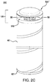
- FIGs 1C and 2C show perspective views of filters 500 comprising the first connector elements 50A ( Figure 1C ) and 50A1 ( Figure 2C ) connected to the second connector element 50B, forming an assembled embodiment of a connector assembly 100, wherein a filter element 401 having a first and a second end has one filter end bonded to an embodiment of the second connector element 50B, and the other filter end bonded to an end cap 601.
- Figures 1C and 2C show an end cap 601 illustrated as a conventional end cap (that can be open or closed; typically, if connector element 50A1 is at one end of the filter, the conventional end cap 601 at the other end of the filter element is open) bonded to the other filter end
- embodiments of the connector assemblies are provided at both ends of the filter element.
- an embodiment of connector assembly 100 as shown in Figure 1C can be at both ends of the filter element, or an embodiment of connector assembly 100 as shown in Figure 1C can be at one end of the filter element, and an embodiment of connector assembly 100 as shown in Figure 2C can be at the other end of the filter element.
- Each first connector element 50A ( Figures 1A and 1B ), and 50A1 ( Figures 2A and 2B ) includes, projecting upwardly from the base 30A, a concentrically arranged crown 90A, including a snap tooth lock 26A, extending in a circumferential direction forming a snap arch 25A wherein the connector elements each also include a snap arm 20A, including a snap tooth 22A, illustrated as having a snap ramp 21A.
- first connector element 50A, 50A1 includes a centering rib 23A and a snap root 24A.
- each first connector element and each second connector element has at least two crowns each including a snap arches, and at least two snap arms as described with respect to Figure 3 ( see, for example, Figure 7 ).
- each first and second connector element has crowns and snap teeth locks; snap arms and snap teeth/snap ramps; centering ribs and snap roots, equally spaced from one another in a circumferential direction.
- the first connector elements 50A and 50A1 each include, projecting upwardly from the base 30A, two cylindrical walls 80A, 80A', each having a hyperbolic paraboloid shape with an uppermost part 81A, 81A,' wherein the cylindrical walls have uniform acclivity .
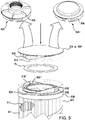
- Figure 3 shows an unassembled end cap assembly 100 according to an embodiment of the invention, comprising first connector element 50A, 50A1, and second connector element 50B, also showing an annular gasket 75 having a central opening 76, arranged between the first and second connector elements, wherein one end of a hollow cylindrical filter element 401 is bound to the second connector element.
- the second connector element 50B includes a central opening 51B for fluid flow.
- Figure 3 also shows that the second connector element 50B has, projecting upwardly from the base 30B, two cylindrical walls 80B, 80B,' each having a hyperbolic paraboloid shape, with uniform acclivity, and as shown in Figure 4C , the uppermost parts 81A, 81A', 81B, 81B'of the walls of one connector element align with the lowermost parts of the walls of the other connector ( see, for example, lowermost parts 82B and 82B' of the second connector 50B as shown in Figure 4A ) when the connector elements are joined.
- FIG 3 also shows, for second connector element 50B (similar to elements shown for first connector elements 50A and 50A1 described in Figures 1A, 1B , 2A, and 2B ), second connector element 50B including, projecting upwardly from the base 30B, a respective concentrically arranged crown 90B, including a snap tooth lock 26B, extending in a circumferential direction forming a snap arch 25B, wherein the connector element also includes a snap arm 20B, including a snap tooth 22B, having a snap ramp 21B.
- second connector element 50B includes a centering rib 23B and a snap root 24B.
- each first and second connector element has at least two crowns each including a snap arches, and at least two snap arms as described with respect to Figure 3 ( see, for example, Figure 7 ).
- each connector element has crowns and snap teeth locks; snap arms and snap teeth/snap ramps; centering ribs and snap roots, equally spaced from one another in a circumferential direction.
- the snap ramps pass over the snap arches and secure the snap teeth into the snap teeth locks, and spring back to their original configuration such that the snap arches retain the trailing edges of the snap teeth and prevent reverse axial action out of the snap teeth locks.
- the snap connector elements cannot be disengaged without damaging the elements, unless a special tool is used.
- Figures 1B and 2B show, projecting upwardly from the base 30A, concentrically arranged circular inner sealing wall 10A and outer sealing wall 11A of first connector elements 50A and 50A1
- Figures 3 , and 4A show, projecting upwardly from the base 30B, concentrically arranged circular inner sealing wall 10B and outer sealing wall 11B of second connector element 50B.
- the angular peaks or tips of the sealing walls 10A, 10B, 11A, 11B compress the upper and lower planar surfaces of the gasket 75 when the connector elements are joined, providing a seal.
- each second connector element includes an annular channel (typically, generally U-shaped channel) 120B formed by concentrically arranged circular inner walls 110B and outer walls 111B, defining a space for receiving an end of the filter elements. While the filter elements are illustrated with an outer cage 421 contacting the outer wall 111B, the cages are optional. The ends of the filter elements in the channels are preferably bound therein, e.g., by adhesive or other bonding reagents and/or techniques known in the art.
- one of the first or second ends of the hollow cylindrical filter element is received in the annular channel 120B of the second connector element, and the other of the first or second ends of the hollow cylindrical filter element is received in an annular channel of an additional second connector element which is lockably engageable with an additional first connector element, or, one of the first or second ends of the hollow cylindrical filter element is received in the annular channel 120B of the second connector element, and the other of the first or second ends of the hollow cylindrical filter element is connected to a conventional end cap.
- the filter elements can have a hollow cylindrical configuration, in some embodiments, a pleated hollow cylindrical configuration.
- Figures 4A and 5 show a pleated hollow cylindrical filter element 401 including pleats 411.
- a filter can include additional elements, layers, or components, that can have different structures and/or functions, e.g., at least one of any one or more of the following: prefiltration, support, drainage, spacing and cushioning.
- the filter can also include at least one additional element such as a mesh and/or a screen.
- Figures 4A , 5 , and 8-10 show filter elements with an outer screen 421.
- At least one filter is typically disposed in a filter housing comprising at least one inlet and at least one outlet and defining at least one fluid flow path between the inlet and the outlet, wherein the filter assembly is across the fluid flow path, to provide a filter device.
- the filter device is sterilizable. Any housing of suitable shape and providing at least one inlet and at least one outlet may be employed.
- the connector elements can be fabricated from any suitable impervious material, e.g., a resilient plastic material that can temporarily deform and spring back to their original configuration, which is compatible with the fluid being processed.
- the gasket is typically a pliant elastomeric material.
- the filter device housing can be fabricated from any suitable rigid impervious material, including any impervious thermoplastic material, which is compatible with the fluid being processed.
- the housing can be fabricated from a metal, such as stainless steel, or from a polymer.
Landscapes
- Chemical & Material Sciences (AREA)
- Chemical Kinetics & Catalysis (AREA)
- Physics & Mathematics (AREA)
- Geometry (AREA)
- Filtration Of Liquid (AREA)
- Filtering Of Dispersed Particles In Gases (AREA)
- Separation Using Semi-Permeable Membranes (AREA)
Abstract
Description
- Filters and filter elements can be provided with end caps. However, attaching the end caps can be labor intensive and/or costly.
- The present invention provides for ameliorating at least some of the disadvantages of the prior art. These and other advantages of the present invention will be apparent from the description as set forth below.
- An embodiment of the invention provides an end cap assembly comprising (a) a first connector element comprising at least two first connector snap arches, each of the at least two first connector snap arches including a snap tooth lock; and at least two first connector snap arms, each of the at least two first connector snap arms including a snap tooth; the first connector element having a central cavity closed off with a wall; (b) a second connector element comprising at least two second connector snap arches, each of the at least two second connector snap arches including a snap tooth lock; and at least two second connector snap arms, each of the at least two second connector snap arms including a snap tooth; the second connector element having a central opening, and an annular channel for receiving an end of a hollow cylindrical filter element; and, (c) a gasket arranged between the first connector element and the second connector element, the gasket having a central opening; wherein the first connector element and the second connector element are lockably engageable with each other when placed in contact with each other and axial force is applied such that each first connector snap tooth is retained in each respective second connector snap tooth lock, and each second connector snap tooth is retained in each respective first connector snap tooth lock.
- An end cap assembly according to another embodiment of the invention comprises (a) a first connector element comprising at least two first connector snap arches, each of the at least two first connector snap arches including a snap tooth lock; and at least two first connector snap arms, each of the at least two first connector snap arms including a snap tooth; the first connector element having a central opening with side walls having an internal thread; (b) a second connector element comprising at least two second connector snap arches, each of the at least two second connector snap arches including a snap tooth lock; and at least two second connector snap arms, each of the at least two second connector snap arms including a snap tooth; the second connector element having a central opening, and an annular channel for receiving an end of a hollow cylindrical filter element; and, (c) a gasket arranged between the first connector element and the second connector element, the gasket having a central opening; wherein the first connector element and the second connector element are lockably engageable with each other when placed in contact with each other and axial force is applied such that each first connector snap tooth is retained in each respective second connector snap tooth lock, and each second connector snap tooth is retained in each respective first connector snap tooth lock.
- In another embodiment, a filter comprises (a) a first connector element comprising at least two first connector snap arches, each of the at least two first connector snap arches including a snap tooth lock; and at least two first connector snap arms, each of the at least two first connector snap arms including a snap tooth; the first connector element having a central cavity closed off with a wall; (b) a second connector element comprising at least two second connector snap arches, each of the at least two second connector snap arches including a snap tooth lock; and at least two second connector snap arms, each of the at least two second connector snap arms including a snap tooth; the second connector element having a central opening, and an annular channel receiving an end of a hollow cylindrical filter element; (c) the hollow cylindrical filter element, having a first end and a second end; and, (d) a gasket arranged between the first connector element and the second connector element, the gasket having a central opening; wherein the first connector element and the second connector element are lockably engageable with each other when placed in contact with each other and axial force is applied such that each first connector snap tooth is retained in each respective second connector snap tooth lock, and each second connector snap tooth is retained in each respective first connector snap tooth lock.
- In another embodiment, a filter comprises (a) a first connector element comprising at least two first connector snap arches, each of the at least two first connector snap arches including a snap tooth lock; and at least two first connector snap arms, each of the at least two first connector snap arms including a snap tooth; the first connector element having a central opening with side walls having an internal thread; (b) a second connector element comprising at least two second connector snap arches, each of the at least two second connector snap arches including a snap tooth lock; and at least two second connector snap arms, each of the at least two second connector snap arms including a snap tooth; the second connector element having a central opening, and an annular channel receiving an end of a hollow cylindrical filter element; (c) the hollow cylindrical filter element, having a first end and a second end; and, (d) a gasket arranged between the first connector element and the second connector element, the gasket having a central opening; wherein the first connector element and the second connector element are lockably engageable with each other when placed in contact with each other and axial force is applied such that each first connector snap tooth is retained in each respective second connector snap tooth lock, and each second connector snap tooth is retained in each respective first connector snap tooth lock.
- A method of attaching an end cap to a filter element according to another embodiment of the invention comprises axially aligning (a) a first connector element comprising at least two first connector snap arches, each of the at least two first connector snap arches including a snap tooth lock; and at least two first connector snap arms, each of the at least two first connector snap arms including a snap tooth; the first connector element having a central cavity closed off with a wall; with (b) a second connector element comprising at least two second connector snap arches, each of the at least two second connector snap arches including a snap tooth lock; and at least two second connector snap arms, each of the at least two second connector snap arms including a snap tooth; the second connector element having a central opening, and an annular channel receiving an end of a hollow cylindrical filter element having a first end and a second end; wherein (c) a gasket is arranged between the first connector element and the second connector element, the gasket having a central opening; and, applying an axial force to the first connector element or the filter element such that each first connector snap tooth is retained in each respective second connector snap tooth lock, and each second connector snap tooth is retained in each respective first connector snap lock.
- A method of attaching an end cap to a filter element according to another embodiment of the invention comprises axially aligning (a) a first connector element comprising at least two first connector snap arches, each of the at least two first connector snap arches including a snap tooth lock; and at least two first connector snap arms, each of the at least two first connector snap arms including a snap tooth; the first connector element having a central opening with side walls having an internal thread; with (b) a second connector element comprising at least two second connector snap arches, each of the at least two second connector snap arches including a snap tooth lock; and at least two second connector snap arms, each of the at least two second connector snap arms including a snap tooth; the second connector element having a central opening, and an annular channel receiving an end of a hollow cylindrical filter element having a first end and a second end; wherein (c) a gasket is arranged between the first connector element and the second connector element, the gasket having a central opening; and, applying an axial force to the first connector element or the filter element such that each first connector snap tooth is retained in each respective second connector snap tooth lock, and each second connector snap tooth is retained in each respective first connector snap lock.
-
-
Figure 1A shows a top perspective view of a first connector element of an open end cap assembly according to an embodiment of the invention, the first connector element having a central opening with side walls having an internal thread;Figure 1B shows a bottom perspective view of the first connector element shown inFigure 1A ;Figure 1C shows a perspective view of the first connector element shown inFigure 1A joined to a second connector element, also showing a cylindrical filter element, wherein one end of the cylindrical filter element is bound in an annular channel in the second connector element, and a conventional end cap is bound to the other end of the cylindrical filter element. -
Figure 2A shows a top perspective view of a first connector element of a closed end cap assembly according to another embodiment of the invention, the first connector element having a central cavity closed off with a wall;Figure 2B shows a bottom perspective view of the first connector element cap shown inFigure 2A ;Figure 2C shows a perspective view of the first connector element shown inFigure 2A joined to a second connector element, also showing a cylindrical filter element, wherein one end of the cylindrical filter element is bound in an annular channel in the second connector element, and a conventional end cap is bound to the other end of the cylindrical filter element. -
Figure 3 shows partial views of unassembled end cap assemblies comprising first connector elements as shown inFigures 1A and 1B , and a second connector element, before the first and second connector elements are joined together, also showing the second connector element including two walls each having a hyperbolic paraboloid shape.Figure 3 also shows a hollow cylindrical filter element bound to the second connector element, and a second connector has a central opening for fluid flow. -
Figure 4A shows a view similar to that shown inFigure 3 , showing the connector elements including walls having hyperbolic paraboloid shapes without showing the snap arches and snap arms shown inFigure 3 .Figure 4B shows the connector elements aligned before they will be connected by axial force.Figure 4C shows alignment between the walls of each connector element having hyperbolic paraboloid shapes, such that the uppermost part of one wall of one connector element aligns with the lowermost part of the corresponding wall of the other connector element. -
Figure 5 shows a fragmented exploded perspective view similar to that shown inFigures 3 and4A , wherein the walls having hyperbolic paraboloid shapes are included, also including a snap tooth lock, a snap arch including a snap tooth, and a snap arm in phantom. The arrow shows the direction that applied axial force will connect the connector elements. The downwardly facing arrow shows the direction that applied axial force will connect the connector elements. -
Figure 6 is a partial exploded perspective view of a part of a connector element, showing a snap arm including a snap tooth having a snap ramp and a snap nose, and a centering rib. The illustrated structures are present in both the first connector element and the second connector element. -
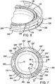
Figure 7 is a cross-sectional plan view of the assembled end cap assemblies shown inFigures 1C and2C , taken along line AA-AA ofFigure 1C and line BB-BB ofFigure 2C . -
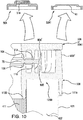
Figure 8 is a fragmented cross-sectional view taken along line AT-AT ofFigure 7 . -
Figure 9 is a fragmented cross-sectional view taken along line AU-AU ofFigure 7 . -
Figure 10 is a fragmented cross-sectional view taken along line AV-AV ofFigure 7 . - An embodiment of the invention provides an end cap assembly comprising (a) a first connector element comprising at least two first connector element snap arches, each of the at least two first connector element snap arches including a snap tooth lock; and at least two first connector element snap arms, each of the at least two first connector element snap arms including a snap tooth; the first connector element having a central cavity closed off with a wall; (b) a second connector element comprising at least two second connector element snap arches, each of the at least two second connector element snap arches including a snap tooth lock; and at least two second connector element snap arms, each of the at least two second connector element snap arms including a snap tooth; the second connector element having a central opening, and an annular channel for receiving an end of a hollow cylindrical filter element; and, (c) a gasket arranged between the first connector element and the second connector element, the gasket having a central opening; wherein the first connector element and the second connector element are lockably engageable with each other when placed in contact with each other and axial force is applied such that each first connector element snap tooth is retained in each respective second connector element snap tooth lock, and each second connector element snap tooth is retained in each respective first connector element snap tooth lock.
- An end cap assembly according to another embodiment of the invention comprises (a) a first connector element comprising at least two first connector element snap arches, each of the at least two first connector element snap arches including a snap tooth lock; and at least two first connector element snap arms, each of the at least two first connector element snap arms including a snap tooth; the first connector element having a central opening with side walls having an internal thread; (b) a second connector element comprising at least two second connector element snap arches, each of the at least two second connector element snap arches including a snap tooth lock; and at least two second connector element snap arms, each of the at least two second connector element snap arms including a snap tooth; the second connector element having a central opening, and an annular channel for receiving an end of a hollow cylindrical filter element; and, (c) a gasket arranged between the first connector element and the second connector element, the gasket having a central opening; wherein the first connector element and the second connector element are lockably engageable with each other when placed in contact with each other and axial force is applied such that each first connector element snap tooth is retained in each respective second connector element snap tooth lock, and each second connector element snap tooth is retained in each respective first connector element snap tooth lock.
- In a typical embodiment, each connector element snap tooth includes a snap ramp.
- In a preferred embodiment, each of the first and second connector elements includes two walls, each wall having a hyperbolic paraboloid shape.
- In another embodiment, a filter comprises (a) a first connector element comprising at least two first connector element snap arches, each of the at least two first connector element snap arches including a snap tooth lock; and at least two first connector element snap arms, each of the at least two first connector element snap arms including a snap tooth; the first connector element having a central cavity closed off with a wall; (b) a second connector element comprising at least two second connector element snap arches, each of the at least two second connector element snap arches including a snap tooth lock; and at least two second connector element snap arms, each of the at least two second connector element snap arms including a snap tooth; the second connector element having a central opening, and an annular channel receiving an end of a hollow cylindrical filter element; (c) the hollow cylindrical filter element, having a first end and a second end; and, (d) a gasket arranged between the first connector element and the second connector element, the gasket having a central opening; wherein the first connector element and the second connector element are lockably engageable with each other when placed in contact with each other and axial force is applied such that each first connector element snap tooth is retained in each respective second connector element snap tooth lock, and each second connector element snap tooth is retained in each respective first connector element snap tooth lock.
- In another embodiment, a filter comprises (a) a first connector element comprising at least two first connector element snap arches, each of the at least two first connector element snap arches including a snap tooth lock; and at least two first connector element snap arms, each of the at least two first connector element snap arms including a snap tooth; the first connector element having a central opening with side walls having an internal thread; (b) a second connector element comprising at least two second connector element snap arches, each of the at least two second connector element snap arches including a snap tooth lock; and at least two second connector element snap arms, each of the at least two second connector element snap arms including a snap tooth; the second connector element having a central opening, and an annular channel receiving an end of a hollow cylindrical filter element; (c) the hollow cylindrical filter element, having a first end and a second end; and, (d) a gasket arranged between the first connector element and the second connector element, the gasket having a central opening; wherein the first connector element and the second connector element are lockably engageable with each other when placed in contact with each other and axial force is applied such that each first connector element snap tooth is retained in each respective second connector element snap tooth lock, and each second connector element snap tooth is retained in each respective first connector element snap tooth lock.
- In some embodiments of the filter, one of the first or second ends of the hollow cylindrical filter element is received in the annular channel of the second connector element, and the other of the first or second ends of the hollow cylindrical filter element is received in an annular channel of an additional second connector element which is lockably engageable with an additional first connector element, or, one of the first or second ends of the hollow cylindrical filter element is received in the annular channel of the second connector element, and the other of the first or second ends of the hollow cylindrical filter element is connected to a conventional end cap.
- A method of attaching an end cap to a filter element according to another embodiment of the invention comprises axially aligning (a) a first connector element comprising at least two first connector element snap arches, each of the at least two first connector element snap arches including a snap tooth lock; and at least two first connector element snap arms, each of the at least two first connector element snap arms including a snap tooth; the first connector element having a central cavity closed off with a wall; with (b) a second connector element comprising at least two second connector element snap arches, each of the at least two second connector element snap arches including a snap tooth lock; and at least two second connector element snap arms, each of the at least two second connector element snap arms including a snap tooth; the second connector element having a central opening, and an annular channel receiving an end of a hollow cylindrical filter element having a first end and a second end; wherein (c) a gasket is arranged between the first connector element and the second connector element, the gasket having a central opening; and, applying an axial force to the first connector element or the filter element such that each first connector element snap tooth is retained in each respective second connector element snap tooth lock, and each second connector element snap tooth is retained in each respective first connector element snap lock.
- A method of attaching an end cap to a filter element according to another embodiment of the invention comprises axially aligning (a) a first connector element comprising at least two first connector element snap arches, each of the at least two first connector element snap arches including a snap tooth lock; and at least two first connector s element nap arms, each of the at least two first connector element snap arms including a snap tooth; the first connector element having a central opening with side walls having an internal thread; with (b) a second connector element comprising at least two second connector element snap arches, each of the at least two second connector element snap arches including a snap tooth lock; and at least two second connector element snap arms, each of the at least two second connector element snap arms including a snap tooth; the second connector element having a central opening, and an annular channel receiving an end of a hollow cylindrical filter element having a first end and a second end; wherein (c) a gasket is arranged between the first connector element and the second connector element, the gasket having a central opening; and, applying an axial force to the first connector element or the filter element such that each first connector element snap tooth is retained in each respective second connector element snap tooth lock, and each second connector element snap tooth is retained in each respective first connector element snap lock.
- A filter device according to an embodiment of the invention comprises an embodiment of at least one filter arranged in a housing having an inlet and an outlet and defining a fluid flow path between the inlet and the outlet with the filter arranged across the fluid flow path.
- A method of filtration according to an embodiment of the invention comprises passing a fluid along the fluid flow path through embodiment of the filter device.
- A variety of fluids can be processed using embodiment of the filter. In one embodiment, the filter device comprises a coalescer, coalescing water and/or oil (and in some embodiments, removing particulate matter) from the stream of fluid being processed.
- Advantageously, separate filters having various filter element lengths can be produced in advance and shipped, providing a cost-effective option for obtaining different filters for different applications. Alternatively, or additionally, different filter element end caps can be bound to filter elements to provide more options for the resultant final filter and filter device.
- Each of the components of the invention will now be described in more detail below, wherein like components have like reference numbers. In accordance with the illustrated embodiments the first and second connector elements have some of the same corresponding elements, and thus, those components have the same names.
- As will be discussed in more detail below, the illustrated embodiments of the
first connector elements 50A and 50A1, and thesecond connector elements 50B each have the following like components (reference numbers will be provided with the figure descriptions below): - Two cylindrical walls projecting upwardly from the base, each wall having a hyperbolic paraboloid shape with an uppermost part, wherein the cylindrical walls have uniform acclivity. Each connector element includes, projecting upwardly from the base, a concentrically arranged crown including a snap tooth lock, extending in a circumferential direction forming a snap arch wherein the connector elements each also include a snap arm including a snap tooth preferably having a snap ramp, and a centering rib and a snap root. The presence of centering ribs, that are present between the outside of a snap arm and the inside of a crown, can be desirable in reducing or preventing radial sliding, e.g., coaxial dislocation of the two connector elements once connected or assembled. Preferably, each first connector element and each second connector element has at least two crowns each including a snap arches, and at least two snap arms.
- After the first and second elements are brought together, positioned coaxially with the respect snap teeth aligned with the snap teeth locks, and with a gasket placed coaxially between the elements, axial force is applied and the respective snap arches are engaged and the snap arms are slightly flexed inwardly and the snap arches are slightly deflected outwardly, and the snap teeth pass over the snap arches into the snap teeth locks. The snap ramps pass over the snap arches and secure the snap teeth into the snap teeth locks, and spring back to their original configuration such that the snap arches retain the trailing edges of the snap teeth and prevent reverse axial action out of the snap teeth locks.
-
Figures 1A and 1B show, respectively, top and bottom perspective views of afirst connector element 50A of an open end cap assembly according to an embodiment of the invention, the first connector element having acentral opening 51A with side walls having aninternal thread 65. The presence of the central opening with an internal thread allows the connection to a threaded adapter and/or threaded filter housing.Figure 1B also shows anoptional collar 48 and optionalcollar support ribs 47. -
Figures 2A and 2B shows, respectively, top and bottom perspective views of a first connector element 50A1 of a closed end cap assembly according to another embodiment of the invention, the first connector element having acentral cavity 45 closed off with awall 41 having an inner surface 41' and anouter surface 41". While theouter surface 41" can have a variety of configuration, e.g., planar or substantially planar,Figure 2A shows an optional raisedportion 43. -
Figures 1C and2C show perspective views offilters 500 comprising thefirst connector elements 50A (Figure 1C ) and 50A1 (Figure 2C ) connected to thesecond connector element 50B, forming an assembled embodiment of aconnector assembly 100, wherein afilter element 401 having a first and a second end has one filter end bonded to an embodiment of thesecond connector element 50B, and the other filter end bonded to anend cap 601. WhileFigures 1C and2C show anend cap 601 illustrated as a conventional end cap (that can be open or closed; typically, if connector element 50A1 is at one end of the filter, theconventional end cap 601 at the other end of the filter element is open) bonded to the other filter end, in other embodiments, embodiments of the connector assemblies are provided at both ends of the filter element. For example, an embodiment ofconnector assembly 100 as shown inFigure 1C can be at both ends of the filter element, or an embodiment ofconnector assembly 100 as shown inFigure 1C can be at one end of the filter element, and an embodiment ofconnector assembly 100 as shown inFigure 2C can be at the other end of the filter element. - Each
first connector element 50A (Figures 1A and 1B ), and 50A1 (Figures 2A and 2B ) includes, projecting upwardly from thebase 30A, a concentrically arrangedcrown 90A, including asnap tooth lock 26A, extending in a circumferential direction forming asnap arch 25A wherein the connector elements each also include asnap arm 20A, including asnap tooth 22A, illustrated as having asnap ramp 21A. In these illustrated embodiments (see also,Figure 6 showing like components in thesecond connector element 50B)first connector element 50A, 50A1 includes a centeringrib 23A and asnap root 24A. The presence of centering ribs, that are present between the outside of a snap arm and the inside of a crown, can be desirable in reducing or preventing radial sliding. Preferably, each first connector element and each second connector element has at least two crowns each including a snap arches, and at least two snap arms as described with respect toFigure 3 (see, for example,Figure 7 ). In the embodiment illustrated inFigure 7 , each first and second connector element has crowns and snap teeth locks; snap arms and snap teeth/snap ramps; centering ribs and snap roots, equally spaced from one another in a circumferential direction. - The
first connector elements 50A and 50A1 each include, projecting upwardly from thebase 30A, twocylindrical walls uppermost part -
Figure 3 shows an unassembledend cap assembly 100 according to an embodiment of the invention, comprisingfirst connector element 50A, 50A1, andsecond connector element 50B, also showing anannular gasket 75 having acentral opening 76, arranged between the first and second connector elements, wherein one end of a hollowcylindrical filter element 401 is bound to the second connector element. Thesecond connector element 50B includes acentral opening 51B for fluid flow. -
Figure 3 also shows that thesecond connector element 50B has, projecting upwardly from thebase 30B, twocylindrical walls Figure 4C , theuppermost parts lowermost parts second connector 50B as shown inFigure 4A ) when the connector elements are joined. -
Figure 3 also shows, forsecond connector element 50B (similar to elements shown forfirst connector elements 50A and 50A1 described inFigures 1A, 1B ,2A, and 2B ),second connector element 50B including, projecting upwardly from thebase 30B, a respective concentrically arrangedcrown 90B, including asnap tooth lock 26B, extending in a circumferential direction forming a snap arch 25B, wherein the connector element also includes asnap arm 20B, including asnap tooth 22B, having asnap ramp 21B. In this illustrated embodiment (also shown inFigure 6 ),second connector element 50B includes a centeringrib 23B and asnap root 24B. Preferably, each first and second connector element has at least two crowns each including a snap arches, and at least two snap arms as described with respect toFigure 3 (see, for example,Figure 7 ). In the embodiment illustrated inFigure 5 , each connector element has crowns and snap teeth locks; snap arms and snap teeth/snap ramps; centering ribs and snap roots, equally spaced from one another in a circumferential direction. - As discussed above, when the first and second elements are brought together, positioned coaxially with the respect snap teeth aligned with the snap teeth locks, and with the gasket placed coaxially between the elements, axial force is applied and the respective snap arches are engaged and the snap arms are slightly flexed inwardly and the snap arches are slightly deflected outwardly, and the snap teeth pass over the snap arches into the snap teeth locks. This action occurs simultaneously circumferentially with all of the snap arches and snap arms. The outermost diameter of all of the snap teeth should be congruent with the outermost surface of the snap teeth locks to maintain a fluid-tight seal.
- The snap ramps pass over the snap arches and secure the snap teeth into the snap teeth locks, and spring back to their original configuration such that the snap arches retain the trailing edges of the snap teeth and prevent reverse axial action out of the snap teeth locks. As a result, the snap connector elements cannot be disengaged without damaging the elements, unless a special tool is used.
-
Figures 1B and2B show, projecting upwardly from thebase 30A, concentrically arranged circularinner sealing wall 10A andouter sealing wall 11A offirst connector elements 50A and 50A1, andFigures 3 , and4A show, projecting upwardly from thebase 30B, concentrically arranged circularinner sealing wall 10B andouter sealing wall 11B ofsecond connector element 50B. As shown in more detail in, for example,Figures 8-10 , the angular peaks or tips of the sealingwalls gasket 75 when the connector elements are joined, providing a seal. - As shown in
Figures 8-10 , each second connector element includes an annular channel (typically, generally U-shaped channel) 120B formed by concentrically arranged circularinner walls 110B andouter walls 111B, defining a space for receiving an end of the filter elements. While the filter elements are illustrated with anouter cage 421 contacting theouter wall 111B, the cages are optional. The ends of the filter elements in the channels are preferably bound therein, e.g., by adhesive or other bonding reagents and/or techniques known in the art. - In some embodiments of the filter, one of the first or second ends of the hollow cylindrical filter element is received in the
annular channel 120B of the second connector element, and the other of the first or second ends of the hollow cylindrical filter element is received in an annular channel of an additional second connector element which is lockably engageable with an additional first connector element, or, one of the first or second ends of the hollow cylindrical filter element is received in theannular channel 120B of the second connector element, and the other of the first or second ends of the hollow cylindrical filter element is connected to a conventional end cap. - A variety of filter elements can be used in accordance with the invention, and are known in the art. In accordance with embodiments of the invention, the filter elements can have a hollow cylindrical configuration, in some embodiments, a pleated hollow cylindrical configuration.
Figures 4A and5 show a pleated hollowcylindrical filter element 401 includingpleats 411. - A filter can include additional elements, layers, or components, that can have different structures and/or functions, e.g., at least one of any one or more of the following: prefiltration, support, drainage, spacing and cushioning. Illustratively, the filter can also include at least one additional element such as a mesh and/or a screen.
Figures 4A ,5 , and8-10 show filter elements with anouter screen 421. - At least one filter is typically disposed in a filter housing comprising at least one inlet and at least one outlet and defining at least one fluid flow path between the inlet and the outlet, wherein the filter assembly is across the fluid flow path, to provide a filter device. Preferably, the filter device is sterilizable. Any housing of suitable shape and providing at least one inlet and at least one outlet may be employed.
- The connector elements can be fabricated from any suitable impervious material, e.g., a resilient plastic material that can temporarily deform and spring back to their original configuration, which is compatible with the fluid being processed.
- The gasket is typically a pliant elastomeric material.
- The filter device housing can be fabricated from any suitable rigid impervious material, including any impervious thermoplastic material, which is compatible with the fluid being processed. For example, the housing can be fabricated from a metal, such as stainless steel, or from a polymer.
- All references, including publications, patent applications, and patents, cited herein are hereby incorporated by reference to the same extent as if each reference were individually and specifically indicated to be incorporated by reference and were set forth in its entirety herein.
- The use of the terms "a" and "an" and "the" and "at least one" and similar referents in the context of describing the invention (especially in the context of the following claims) are to be construed to cover both the singular and the plural, unless otherwise indicated herein or clearly contradicted by context. The use of the term "at least one" followed by a list of one or more items (for example, "at least one of A and B") is to be construed to mean one item selected from the listed items (A or B) or any combination of two or more of the listed items (A and B), unless otherwise indicated herein or clearly contradicted by context. The terms "comprising," "having," "including," and "containing" are to be construed as open-ended terms (i.e., meaning "including, but not limited to,") unless otherwise noted. Recitation of ranges of values herein are merely intended to serve as a shorthand method of referring individually to each separate value falling within the range, unless otherwise indicated herein, and each separate value is incorporated into the specification as if it were individually recited herein. All methods described herein can be performed in any suitable order unless otherwise indicated herein or otherwise clearly contradicted by context. The use of any and all examples, or exemplary language (e.g., "such as") provided herein, is intended merely to better illuminate the invention and does not pose a limitation on the scope of the invention unless otherwise claimed. No language in the specification should be construed as indicating any non-claimed element as essential to the practice of the invention.
- Preferred embodiments of this invention are described herein, including the best mode known to the inventors for carrying out the invention. Variations of those preferred embodiments may become apparent to those of ordinary skill in the art upon reading the foregoing description. The inventors expect skilled artisans to employ such variations as appropriate, and the inventors intend for the invention to be practiced otherwise than as specifically described herein. Accordingly, this invention includes all modifications and equivalents of the subject matter recited in the claims appended hereto as permitted by applicable law. Moreover, any combination of the above-described elements in all possible variations thereof is encompassed by the invention unless otherwise indicated herein or otherwise clearly contradicted by context.
Claims (8)
- An end cap assembly comprising:(a) a first connector element comprising at least two first connector element snap arches, each of the at least two first connector element snap arches including a snap tooth lock; and at least two first connector element snap arms, each of the at least two first connector element snap arms including a snap tooth; the first connector element having a central cavity closed off with a wall;(b) a second connector element comprising at least two second connector element snap arches, each of the at least two second connector element snap arches including a snap tooth lock; and at least two second connector element snap arms, each of the at least two second connector element snap arms including a snap tooth; the second connector element having a central opening, and an annular channel for receiving an end of a hollow cylindrical filter element; and,(c) a gasket arranged between the first connector element and the second connector element, the gasket having a central opening;wherein the first connector element and the second connector element are lockably engageable with each other when placed in contact with each other and axial force is applied such that each first connector element snap tooth is retained in each respective second connector element snap tooth lock, and each second connector element snap tooth is retained in each respective first connector element snap tooth lock.
- An end cap assembly comprising:(a) a first connector element comprising at least two first connector element snap arches, each of the at least two first connector element snap arches including a snap tooth lock; and at least two first connector element snap arms, each of the at least two first connector element snap arms including a snap tooth; the first connector element having a central opening with side walls having an internal thread;(b) a second connector element comprising at least two second connector element snap arches, each of the at least two second connector element snap arches including a snap tooth lock; and at least two second element connector snap arms, each of the at least two second connector element snap arms including a snap tooth; the second connector element having a central opening and an annular channel for receiving an end of a hollow cylindrical filter element; and,(c) a gasket arranged between the first connector element and the second connector element, the gasket having a central opening;wherein the first connector element and the second connector element are lockably engageable with each other when placed in contact with each other and axial force is applied such that each first connector element snap tooth is retained in each respective second connector element snap tooth lock, and each second connector element snap tooth is retained in each respective first connector element snap tooth lock.
- The endcap assembly of claim 1 or 2, wherein each first connector element snap tooth and each second connector element snap tooth includes a snap ramp.
- The endcap assembly of any one of claims 1-3, wherein each first connector element and each second connector element includes two walls, each wall having a hyperbolic paraboloid shape.
- A filter comprising:(a) a first connector element comprising at least two first connector element snap arches, each of the at least two first connector element snap arches including a snap tooth lock; and at least two first connector element snap arms, each of the at least two first connector element snap arms including a snap tooth; the first connector element having a central cavity closed off with a wall;(b) a second connector element comprising at least two second connector element snap arches, each of the at least two second connector element snap arches including a snap tooth lock; and at least two second connector element snap arms, each of the at least two second connector element snap arms including a snap tooth; the second connector element having a central opening, and an annular channel receiving an end of a hollow cylindrical filter element;(c) the hollow cylindrical filter element, having a first end and a second end; and,(d) a gasket arranged between the first connector element and the second connector element, the gasket having a central opening; wherein the first connector element and the second connector element are lockably engageable with each other when placed in contact with each other and axial force is applied such that each first connector element snap tooth is retained in each respective second connector element snap tooth lock, and each second connector element snap tooth is retained in each respective first connector element snap tooth lock.
- A filter comprising:(a) a first connector element comprising at least two first connector element snap arches, each of the at least two first connector element snap arches including a snap tooth lock; and at least two first connector element snap arms, each of the at least two first connector element snap arms including a snap tooth; the first connector element having a central opening with side walls having an internal thread;(b) a second connector element comprising at least two second connector element snap arches, each of the at least two second connector element snap arches including a snap tooth lock; and at least two second connector element snap arms, each of the at least two second connector element snap arms including a snap tooth; the second connector element having a central opening, and an annular channel receiving an end of a hollow cylindrical filter element;(c) the hollow cylindrical filter element, having a first end and a second end; and,(d) a gasket arranged between the first connector element and the second connector element, the gasket having a central opening; wherein the first connector element and the second connector element are lockably engageable with each other when placed in contact with each other and axial force is applied such that each first connector element snap tooth is retained in each respective second connector element snap tooth lock, and each second connector element snap tooth is retained in each respective first connector element snap tooth lock.
- A method of attaching an end cap to a filter element, the method comprising axially aligning(a) a first connector element comprising at least two first connector element snap arches, each of the at least two first connector element snap arches including a snap tooth lock; and at least two first connector element snap arms, each of the at least two first connector element snap arms including a snap tooth; the first connector element having a central cavity closed off with a wall; with,(b) a second connector element comprising at least two second connector element snap arches, each of the at least two second connector snap arches including a snap tooth lock; and at least two second connector element snap arms, each of the at least two second connector element snap arms including a snap tooth; the second connector element having a central opening, and an annular channel having a first or second end of a hollow cylindrical filter element bound therein; wherein(c) a gasket is arranged between the first connector element and the second connector element, the gasket having a central opening; and, applying an axial force to the first connector element or the filter element such that each first connector element snap tooth is retained in each respective second connector element snap tooth lock, and each second connector element snap tooth is retained in each respective first connector element snap lock.
- A method of attaching an end cap to a filter element, the method comprising axially aligning(a) a first connector element comprising at least two first connector element snap arches, each of the at least two first connector element snap arches including a snap tooth lock; and at least two first connector element snap arms, each of the at least two first connector element snap arms including a snap tooth; the first connector element having a central opening with side walls having an internal thread; with,(b) a second connector element comprising at least two second connector element snap arches, each of the at least two second connector element snap arches including a snap tooth lock; and at least two second connector element snap arms, each of the at least two second connector element snap arms including a snap tooth; the second connector element having a central opening, and an annular channel having a first or second end of a hollow cylindrical filter element bound therein; wherein(c) a gasket is arranged between the first connector element and the second connector element, the gasket having a central opening; and,applying an axial force to the first connector element or the filter element such that each first connector element snap tooth is retained in each respective second connector element snap tooth lock, and each second connector element snap tooth is retained in each respective first connector element snap lock.
Applications Claiming Priority (1)
| Application Number | Priority Date | Filing Date | Title |
|---|---|---|---|
| US16/796,005 US11291934B2 (en) | 2020-02-20 | 2020-02-20 | End cap assembly, filter, and method of use |
Publications (2)
| Publication Number | Publication Date |
|---|---|
| EP3868456A1 true EP3868456A1 (en) | 2021-08-25 |
| EP3868456B1 EP3868456B1 (en) | 2024-12-25 |
Family
ID=74672064
Family Applications (1)
| Application Number | Title | Priority Date | Filing Date |
|---|---|---|---|
| EP21157773.9A Active EP3868456B1 (en) | 2020-02-20 | 2021-02-18 | End cap assembly, filter, and method of use |
Country Status (5)
| Country | Link |
|---|---|
| US (1) | US11291934B2 (en) |
| EP (1) | EP3868456B1 (en) |
| JP (1) | JP7135245B2 (en) |
| CN (1) | CN113274804B (en) |
| SG (1) | SG10202101610YA (en) |
Cited By (1)
| Publication number | Priority date | Publication date | Assignee | Title |
|---|---|---|---|---|
| CN114042343A (en) * | 2021-11-03 | 2022-02-15 | 上海御渡半导体科技有限公司 | Water tank liquid filter screen assembly in liquid cooling ATE equipment |
Families Citing this family (2)
| Publication number | Priority date | Publication date | Assignee | Title |
|---|---|---|---|---|
| US11173436B2 (en) | 2020-02-20 | 2021-11-16 | Pall Corporation | Connector assembly, filter assembly, filter device, and method of use |
| EP4389252B1 (en) * | 2022-12-22 | 2025-09-03 | Donaldson Company, Inc. | Filter element with convertible end cap and methods |
Citations (5)
| Publication number | Priority date | Publication date | Assignee | Title |
|---|---|---|---|---|
| US20060186031A1 (en) * | 2005-02-22 | 2006-08-24 | Baldwin Filters, Inc. | Filter apparatus |
| US7237682B2 (en) * | 2003-07-01 | 2007-07-03 | Parker-Hannifin Corporation | Filter assembly with slip thread |
| US20110042294A1 (en) * | 2009-08-21 | 2011-02-24 | Diego Bonta | End cap assembly adapted for interconnecting filtration elements |
| EP2789375A1 (en) * | 2013-04-10 | 2014-10-15 | Clarcor Engine Mobile Solutions, LLC | Filter element |
| US20200179840A1 (en) * | 2018-12-11 | 2020-06-11 | A.L. Filter Co., Ltd. | Fluid filter element for circular locking engagement with a filter support |
Family Cites Families (21)
| Publication number | Priority date | Publication date | Assignee | Title |
|---|---|---|---|---|
| US5141637A (en) | 1990-11-30 | 1992-08-25 | Pall Corporation | Filter units with end connectors |
| US5394316A (en) | 1993-04-12 | 1995-02-28 | Welch Allyn, Inc. | Locking lamp assembly for examination light |
| JP3315777B2 (en) | 1993-10-06 | 2002-08-19 | 本田技研工業株式会社 | Filter device |
| DE69624086T2 (en) * | 1995-12-27 | 2003-05-28 | Denso Corp., Kariya | Housing for exchangeable filter cartridges |
| JP2940460B2 (en) | 1996-02-15 | 1999-08-25 | ノーリツ鋼機株式会社 | Processing solution filtration device in automatic processor |
| US6632356B2 (en) | 2001-08-01 | 2003-10-14 | Dow Global Technologies Inc. | Separation membrane end cap |
| EP1490157A4 (en) * | 2002-03-28 | 2008-10-01 | Entegris Inc | Filter cartridge construction |
| US7063730B2 (en) | 2003-10-21 | 2006-06-20 | Fleetguard, Inc. | Filter with end cap base retainer |
| US8057669B2 (en) * | 2005-02-22 | 2011-11-15 | Baldwin Filters, Inc. | Filter element and filter assembly including locking mechanism |
| JP2007046522A (en) | 2005-08-09 | 2007-02-22 | Honda Motor Co Ltd | Lid separation type container |
| GB0812457D0 (en) * | 2008-07-08 | 2008-08-13 | Parker Hannifin U K Ltd | A Filter |
| IT1398974B1 (en) | 2010-03-24 | 2013-03-28 | Ufi Filters Spa | FILTER FOR INTERNAL COMBUSTION ENGINES. |
| US20140183118A1 (en) * | 2011-08-05 | 2014-07-03 | Evan Marks | Slip thread locking head with interactive element |
| US9550135B2 (en) | 2013-01-14 | 2017-01-24 | Clarcor Engine Mobile Solutions, Llc | Fuel filter assembly and cartridge |
| US9067154B1 (en) * | 2014-11-06 | 2015-06-30 | 3M Innovative Properties Company | Replacement filter cartridge |
| JP2017166459A (en) | 2016-03-18 | 2017-09-21 | 株式会社ケーヒン | Fuel filter and fuel pump module |
| CN206837595U (en) * | 2017-05-25 | 2018-01-05 | 佛山市顺德区美的饮水机制造有限公司 | Filter core and water purifier |
| CN107185295A (en) * | 2017-06-08 | 2017-09-22 | 厦门建霖工业有限公司 | A kind of filter cartridge construction |
| CN107823957A (en) * | 2017-12-12 | 2018-03-23 | 上海浩泽净水科技发展有限公司 | A kind of filter element of water purifier anti-counterfeit structure and method |
| CN108176121B (en) * | 2018-01-16 | 2024-02-09 | 宁波博乐宝科技有限公司 | Filter flask assembly, valve body assembly, filter device and water purifier |
| US11173436B2 (en) | 2020-02-20 | 2021-11-16 | Pall Corporation | Connector assembly, filter assembly, filter device, and method of use |
-
2020
- 2020-02-20 US US16/796,005 patent/US11291934B2/en active Active
-
2021
- 2021-02-17 SG SG10202101610YA patent/SG10202101610YA/en unknown
- 2021-02-17 JP JP2021023463A patent/JP7135245B2/en active Active
- 2021-02-18 EP EP21157773.9A patent/EP3868456B1/en active Active
- 2021-02-20 CN CN202110193189.0A patent/CN113274804B/en active Active
Patent Citations (5)
| Publication number | Priority date | Publication date | Assignee | Title |
|---|---|---|---|---|
| US7237682B2 (en) * | 2003-07-01 | 2007-07-03 | Parker-Hannifin Corporation | Filter assembly with slip thread |
| US20060186031A1 (en) * | 2005-02-22 | 2006-08-24 | Baldwin Filters, Inc. | Filter apparatus |
| US20110042294A1 (en) * | 2009-08-21 | 2011-02-24 | Diego Bonta | End cap assembly adapted for interconnecting filtration elements |
| EP2789375A1 (en) * | 2013-04-10 | 2014-10-15 | Clarcor Engine Mobile Solutions, LLC | Filter element |
| US20200179840A1 (en) * | 2018-12-11 | 2020-06-11 | A.L. Filter Co., Ltd. | Fluid filter element for circular locking engagement with a filter support |
Cited By (1)
| Publication number | Priority date | Publication date | Assignee | Title |
|---|---|---|---|---|
| CN114042343A (en) * | 2021-11-03 | 2022-02-15 | 上海御渡半导体科技有限公司 | Water tank liquid filter screen assembly in liquid cooling ATE equipment |
Also Published As
| Publication number | Publication date |
|---|---|
| JP2021137800A (en) | 2021-09-16 |
| CN113274804B (en) | 2022-04-12 |
| US20210260506A1 (en) | 2021-08-26 |
| JP7135245B2 (en) | 2022-09-13 |
| CN113274804A (en) | 2021-08-20 |
| EP3868456B1 (en) | 2024-12-25 |
| SG10202101610YA (en) | 2021-09-29 |
| US11291934B2 (en) | 2022-04-05 |
Similar Documents
| Publication | Publication Date | Title |
|---|---|---|
| EP3868456A1 (en) | End cap assembly, filter, and method of use | |
| AU736852B2 (en) | Replaceable filter element and snap-on filter lid assembly | |
| AU692514B2 (en) | Cylindrical air filter with radially directed seal and method of manufacturing a housing for same | |
| US8197686B2 (en) | Fuel filter cartridge and keyed end cap | |
| US20250196040A1 (en) | Radial seal for spin-on filter | |
| HU225368B1 (en) | Liquid filter for vehicle internal combustion engines | |
| EP0260069A2 (en) | Filter assembly with threaded collection bowl | |
| JPH08508195A (en) | Compressible differential pressure bias seal for filter elements, etc. | |
| JPH067614A (en) | Sealed connector | |
| US20220339560A1 (en) | J-Hook Filter Assembly | |
| EP4454731A1 (en) | Filter assemblies and related filter elements | |
| WO2013022834A1 (en) | Slip thread locking head with interactive element | |
| EP3868455B1 (en) | Connector assembly, filter assembly, filter device, and method of use | |
| US12042753B2 (en) | Integrated multifunctional endcap seal member | |
| US8747665B2 (en) | Filter container, assembly, and method for manufacturing the same | |
| EP4389252A1 (en) | Filter element with convertible end cap and methods |
Legal Events
| Date | Code | Title | Description |
|---|---|---|---|
| PUAI | Public reference made under article 153(3) epc to a published international application that has entered the european phase |
Free format text: ORIGINAL CODE: 0009012 |
|
| STAA | Information on the status of an ep patent application or granted ep patent |
Free format text: STATUS: THE APPLICATION HAS BEEN PUBLISHED |
|
| AK | Designated contracting states |
Kind code of ref document: A1 Designated state(s): AL AT BE BG CH CY CZ DE DK EE ES FI FR GB GR HR HU IE IS IT LI LT LU LV MC MK MT NL NO PL PT RO RS SE SI SK SM TR |
|
| STAA | Information on the status of an ep patent application or granted ep patent |
Free format text: STATUS: REQUEST FOR EXAMINATION WAS MADE |
|
| 17P | Request for examination filed |
Effective date: 20220223 |
|
| RBV | Designated contracting states (corrected) |
Designated state(s): AL AT BE BG CH CY CZ DE DK EE ES FI FR GB GR HR HU IE IS IT LI LT LU LV MC MK MT NL NO PL PT RO RS SE SI SK SM TR |
|
| STAA | Information on the status of an ep patent application or granted ep patent |
Free format text: STATUS: EXAMINATION IS IN PROGRESS |
|
| 17Q | First examination report despatched |
Effective date: 20230303 |
|
| P01 | Opt-out of the competence of the unified patent court (upc) registered |
Effective date: 20230530 |
|
| GRAP | Despatch of communication of intention to grant a patent |
Free format text: ORIGINAL CODE: EPIDOSNIGR1 |
|
| STAA | Information on the status of an ep patent application or granted ep patent |
Free format text: STATUS: GRANT OF PATENT IS INTENDED |
|
| INTG | Intention to grant announced |
Effective date: 20240719 |
|
| GRAS | Grant fee paid |
Free format text: ORIGINAL CODE: EPIDOSNIGR3 |
|
| GRAA | (expected) grant |
Free format text: ORIGINAL CODE: 0009210 |
|
| STAA | Information on the status of an ep patent application or granted ep patent |
Free format text: STATUS: THE PATENT HAS BEEN GRANTED |
|
| AK | Designated contracting states |
Kind code of ref document: B1 Designated state(s): AL AT BE BG CH CY CZ DE DK EE ES FI FR GB GR HR HU IE IS IT LI LT LU LV MC MK MT NL NO PL PT RO RS SE SI SK SM TR |
|
| REG | Reference to a national code |
Ref country code: GB Ref legal event code: FG4D |
|
| REG | Reference to a national code |
Ref country code: CH Ref legal event code: EP |
|
| REG | Reference to a national code |
Ref country code: DE Ref legal event code: R096 Ref document number: 602021023746 Country of ref document: DE |
|
| REG | Reference to a national code |
Ref country code: IE Ref legal event code: FG4D |
|
| REG | Reference to a national code |
Ref country code: LT Ref legal event code: MG9D |
|
| PG25 | Lapsed in a contracting state [announced via postgrant information from national office to epo] |
Ref country code: HR Free format text: LAPSE BECAUSE OF FAILURE TO SUBMIT A TRANSLATION OF THE DESCRIPTION OR TO PAY THE FEE WITHIN THE PRESCRIBED TIME-LIMIT Effective date: 20241225 |
|
| PG25 | Lapsed in a contracting state [announced via postgrant information from national office to epo] |
Ref country code: FI Free format text: LAPSE BECAUSE OF FAILURE TO SUBMIT A TRANSLATION OF THE DESCRIPTION OR TO PAY THE FEE WITHIN THE PRESCRIBED TIME-LIMIT Effective date: 20241225 |
|
| PG25 | Lapsed in a contracting state [announced via postgrant information from national office to epo] |
Ref country code: BG Free format text: LAPSE BECAUSE OF FAILURE TO SUBMIT A TRANSLATION OF THE DESCRIPTION OR TO PAY THE FEE WITHIN THE PRESCRIBED TIME-LIMIT Effective date: 20241225 |
|
| PG25 | Lapsed in a contracting state [announced via postgrant information from national office to epo] |
Ref country code: NO Free format text: LAPSE BECAUSE OF FAILURE TO SUBMIT A TRANSLATION OF THE DESCRIPTION OR TO PAY THE FEE WITHIN THE PRESCRIBED TIME-LIMIT Effective date: 20250325 |
|
| PG25 | Lapsed in a contracting state [announced via postgrant information from national office to epo] |
Ref country code: LV Free format text: LAPSE BECAUSE OF FAILURE TO SUBMIT A TRANSLATION OF THE DESCRIPTION OR TO PAY THE FEE WITHIN THE PRESCRIBED TIME-LIMIT Effective date: 20241225 Ref country code: GR Free format text: LAPSE BECAUSE OF FAILURE TO SUBMIT A TRANSLATION OF THE DESCRIPTION OR TO PAY THE FEE WITHIN THE PRESCRIBED TIME-LIMIT Effective date: 20250326 |
|
| PGFP | Annual fee paid to national office [announced via postgrant information from national office to epo] |
Ref country code: AT Payment date: 20250417 Year of fee payment: 5 |
|
| PG25 | Lapsed in a contracting state [announced via postgrant information from national office to epo] |
Ref country code: RS Free format text: LAPSE BECAUSE OF FAILURE TO SUBMIT A TRANSLATION OF THE DESCRIPTION OR TO PAY THE FEE WITHIN THE PRESCRIBED TIME-LIMIT Effective date: 20250325 |
|
| REG | Reference to a national code |
Ref country code: NL Ref legal event code: MP Effective date: 20241225 |
|
| PG25 | Lapsed in a contracting state [announced via postgrant information from national office to epo] |
Ref country code: NL Free format text: LAPSE BECAUSE OF FAILURE TO SUBMIT A TRANSLATION OF THE DESCRIPTION OR TO PAY THE FEE WITHIN THE PRESCRIBED TIME-LIMIT Effective date: 20241225 |
|
| REG | Reference to a national code |
Ref country code: AT Ref legal event code: MK05 Ref document number: 1753716 Country of ref document: AT Kind code of ref document: T Effective date: 20241225 |
|
| PG25 | Lapsed in a contracting state [announced via postgrant information from national office to epo] |
Ref country code: SM Free format text: LAPSE BECAUSE OF FAILURE TO SUBMIT A TRANSLATION OF THE DESCRIPTION OR TO PAY THE FEE WITHIN THE PRESCRIBED TIME-LIMIT Effective date: 20241225 |
|
| PG25 | Lapsed in a contracting state [announced via postgrant information from national office to epo] |
Ref country code: PL Free format text: LAPSE BECAUSE OF FAILURE TO SUBMIT A TRANSLATION OF THE DESCRIPTION OR TO PAY THE FEE WITHIN THE PRESCRIBED TIME-LIMIT Effective date: 20241225 |
|
| PG25 | Lapsed in a contracting state [announced via postgrant information from national office to epo] |
Ref country code: ES Free format text: LAPSE BECAUSE OF FAILURE TO SUBMIT A TRANSLATION OF THE DESCRIPTION OR TO PAY THE FEE WITHIN THE PRESCRIBED TIME-LIMIT Effective date: 20241225 |
|
| PG25 | Lapsed in a contracting state [announced via postgrant information from national office to epo] |
Ref country code: IS Free format text: LAPSE BECAUSE OF FAILURE TO SUBMIT A TRANSLATION OF THE DESCRIPTION OR TO PAY THE FEE WITHIN THE PRESCRIBED TIME-LIMIT Effective date: 20250425 |
|
| PG25 | Lapsed in a contracting state [announced via postgrant information from national office to epo] |
Ref country code: PT Free format text: LAPSE BECAUSE OF FAILURE TO SUBMIT A TRANSLATION OF THE DESCRIPTION OR TO PAY THE FEE WITHIN THE PRESCRIBED TIME-LIMIT Effective date: 20250428 |
|
| PG25 | Lapsed in a contracting state [announced via postgrant information from national office to epo] |
Ref country code: EE Free format text: LAPSE BECAUSE OF FAILURE TO SUBMIT A TRANSLATION OF THE DESCRIPTION OR TO PAY THE FEE WITHIN THE PRESCRIBED TIME-LIMIT Effective date: 20241225 |
|
| PG25 | Lapsed in a contracting state [announced via postgrant information from national office to epo] |
Ref country code: RO Free format text: LAPSE BECAUSE OF FAILURE TO SUBMIT A TRANSLATION OF THE DESCRIPTION OR TO PAY THE FEE WITHIN THE PRESCRIBED TIME-LIMIT Effective date: 20241225 Ref country code: AT Free format text: LAPSE BECAUSE OF FAILURE TO SUBMIT A TRANSLATION OF THE DESCRIPTION OR TO PAY THE FEE WITHIN THE PRESCRIBED TIME-LIMIT Effective date: 20241225 |
|
| PG25 | Lapsed in a contracting state [announced via postgrant information from national office to epo] |
Ref country code: SK Free format text: LAPSE BECAUSE OF FAILURE TO SUBMIT A TRANSLATION OF THE DESCRIPTION OR TO PAY THE FEE WITHIN THE PRESCRIBED TIME-LIMIT Effective date: 20241225 |
|
| PG25 | Lapsed in a contracting state [announced via postgrant information from national office to epo] |
Ref country code: CZ Free format text: LAPSE BECAUSE OF FAILURE TO SUBMIT A TRANSLATION OF THE DESCRIPTION OR TO PAY THE FEE WITHIN THE PRESCRIBED TIME-LIMIT Effective date: 20241225 |
|
| PG25 | Lapsed in a contracting state [announced via postgrant information from national office to epo] |
Ref country code: SE Free format text: LAPSE BECAUSE OF FAILURE TO SUBMIT A TRANSLATION OF THE DESCRIPTION OR TO PAY THE FEE WITHIN THE PRESCRIBED TIME-LIMIT Effective date: 20241225 |
|
| PG25 | Lapsed in a contracting state [announced via postgrant information from national office to epo] |
Ref country code: MC Free format text: LAPSE BECAUSE OF FAILURE TO SUBMIT A TRANSLATION OF THE DESCRIPTION OR TO PAY THE FEE WITHIN THE PRESCRIBED TIME-LIMIT Effective date: 20241225 |
|
| REG | Reference to a national code |
Ref country code: DE Ref legal event code: R097 Ref document number: 602021023746 Country of ref document: DE |
|
| REG | Reference to a national code |
Ref country code: CH Ref legal event code: PL |
|
| PG25 | Lapsed in a contracting state [announced via postgrant information from national office to epo] |
Ref country code: DK Free format text: LAPSE BECAUSE OF FAILURE TO SUBMIT A TRANSLATION OF THE DESCRIPTION OR TO PAY THE FEE WITHIN THE PRESCRIBED TIME-LIMIT Effective date: 20241225 |
|
| PG25 | Lapsed in a contracting state [announced via postgrant information from national office to epo] |
Ref country code: LU Free format text: LAPSE BECAUSE OF NON-PAYMENT OF DUE FEES Effective date: 20250218 |
|
| PG25 | Lapsed in a contracting state [announced via postgrant information from national office to epo] |
Ref country code: CH Free format text: LAPSE BECAUSE OF NON-PAYMENT OF DUE FEES Effective date: 20250228 |
|
| PLBE | No opposition filed within time limit |
Free format text: ORIGINAL CODE: 0009261 |
|
| STAA | Information on the status of an ep patent application or granted ep patent |
Free format text: STATUS: NO OPPOSITION FILED WITHIN TIME LIMIT |
|
| 26N | No opposition filed |
Effective date: 20250926 |
|
| REG | Reference to a national code |
Ref country code: BE Ref legal event code: MM Effective date: 20250228 |
|
| PG25 | Lapsed in a contracting state [announced via postgrant information from national office to epo] |
Ref country code: BE Free format text: LAPSE BECAUSE OF NON-PAYMENT OF DUE FEES Effective date: 20250228 |
|
| PG25 | Lapsed in a contracting state [announced via postgrant information from national office to epo] |
Ref country code: IE Free format text: LAPSE BECAUSE OF NON-PAYMENT OF DUE FEES Effective date: 20250218 |
|
| PGFP | Annual fee paid to national office [announced via postgrant information from national office to epo] |
Ref country code: GB Payment date: 20260223 Year of fee payment: 6 |
|
| PGFP | Annual fee paid to national office [announced via postgrant information from national office to epo] |
Ref country code: DE Payment date: 20260220 Year of fee payment: 6 |
|
| PGFP | Annual fee paid to national office [announced via postgrant information from national office to epo] |
Ref country code: IT Payment date: 20260220 Year of fee payment: 6 |
|
| PGFP | Annual fee paid to national office [announced via postgrant information from national office to epo] |
Ref country code: FR Payment date: 20260227 Year of fee payment: 6 |