EP3868304A1 - Biopsy device with transfer of kinetic energy to the needle assembly - Google Patents
Biopsy device with transfer of kinetic energy to the needle assembly Download PDFInfo
- Publication number
- EP3868304A1 EP3868304A1 EP20212373.3A EP20212373A EP3868304A1 EP 3868304 A1 EP3868304 A1 EP 3868304A1 EP 20212373 A EP20212373 A EP 20212373A EP 3868304 A1 EP3868304 A1 EP 3868304A1
- Authority
- EP
- European Patent Office
- Prior art keywords
- biopsy device
- impact
- follower
- impact member
- traveler
- Prior art date
- Legal status (The legal status is an assumption and is not a legal conclusion. Google has not performed a legal analysis and makes no representation as to the accuracy of the status listed.)
- Pending
Links
Images








Classifications
-
- A—HUMAN NECESSITIES
- A61—MEDICAL OR VETERINARY SCIENCE; HYGIENE
- A61B—DIAGNOSIS; SURGERY; IDENTIFICATION
- A61B10/00—Instruments for taking body samples for diagnostic purposes; Other methods or instruments for diagnosis, e.g. for vaccination diagnosis, sex determination or ovulation-period determination; Throat striking implements
- A61B10/02—Instruments for taking cell samples or for biopsy
- A61B10/0233—Pointed or sharp biopsy instruments
- A61B10/0266—Pointed or sharp biopsy instruments means for severing sample
-
- A—HUMAN NECESSITIES
- A61—MEDICAL OR VETERINARY SCIENCE; HYGIENE
- A61B—DIAGNOSIS; SURGERY; IDENTIFICATION
- A61B10/00—Instruments for taking body samples for diagnostic purposes; Other methods or instruments for diagnosis, e.g. for vaccination diagnosis, sex determination or ovulation-period determination; Throat striking implements
- A61B10/02—Instruments for taking cell samples or for biopsy
- A61B10/0233—Pointed or sharp biopsy instruments
- A61B10/0266—Pointed or sharp biopsy instruments means for severing sample
- A61B10/0275—Pointed or sharp biopsy instruments means for severing sample with sample notch, e.g. on the side of inner stylet
-
- A—HUMAN NECESSITIES
- A61—MEDICAL OR VETERINARY SCIENCE; HYGIENE
- A61B—DIAGNOSIS; SURGERY; IDENTIFICATION
- A61B10/00—Instruments for taking body samples for diagnostic purposes; Other methods or instruments for diagnosis, e.g. for vaccination diagnosis, sex determination or ovulation-period determination; Throat striking implements
- A61B10/02—Instruments for taking cell samples or for biopsy
-
- A—HUMAN NECESSITIES
- A61—MEDICAL OR VETERINARY SCIENCE; HYGIENE
- A61B—DIAGNOSIS; SURGERY; IDENTIFICATION
- A61B10/00—Instruments for taking body samples for diagnostic purposes; Other methods or instruments for diagnosis, e.g. for vaccination diagnosis, sex determination or ovulation-period determination; Throat striking implements
- A61B10/02—Instruments for taking cell samples or for biopsy
- A61B10/0233—Pointed or sharp biopsy instruments
-
- A—HUMAN NECESSITIES
- A61—MEDICAL OR VETERINARY SCIENCE; HYGIENE
- A61B—DIAGNOSIS; SURGERY; IDENTIFICATION
- A61B10/00—Instruments for taking body samples for diagnostic purposes; Other methods or instruments for diagnosis, e.g. for vaccination diagnosis, sex determination or ovulation-period determination; Throat striking implements
- A61B10/02—Instruments for taking cell samples or for biopsy
- A61B10/0233—Pointed or sharp biopsy instruments
- A61B10/0241—Pointed or sharp biopsy instruments for prostate
-
- A—HUMAN NECESSITIES
- A61—MEDICAL OR VETERINARY SCIENCE; HYGIENE
- A61B—DIAGNOSIS; SURGERY; IDENTIFICATION
- A61B10/00—Instruments for taking body samples for diagnostic purposes; Other methods or instruments for diagnosis, e.g. for vaccination diagnosis, sex determination or ovulation-period determination; Throat striking implements
- A61B10/02—Instruments for taking cell samples or for biopsy
- A61B2010/0208—Biopsy devices with actuators, e.g. with triggered spring mechanisms
Definitions
- the present disclosure relates generally to medical devices. More specifically, the present disclosure relates to biopsy devices, including biopsy devices configured with an impact driven or kinetic energy operation system.
- the invention is, in particular, related to biopsy devices and methods according to any of the following statements: According to statement 1, the invention relates to a tissue biopsy device, comprising:
- Biopsy devices may be configured to retrieve tissue samples from various locations within a patient's body.
- a biopsy device may comprise a needle assembly including cannula or other cutting members configured to sever a tissue sample.
- the needle assembly may be advanced to a location within the body through the skin of the patient (percutaneous access) or may be advanced through a body lumen or other structure.
- a biopsy device may comprise an actuation mechanism configured to displace the needle assembly such that the needle assembly severs the targeted tissue sample.
- Biasing mechanisms such as springs, triggers, and so forth may be configured to allow a practitioner to manipulate various components of a needle assembly through manipulating the actuation mechanism.
- compressed gas or other energy sources may be configured to power a biopsy device.
- a compressed CO 2 cartridge may be used to power a biopsy device.
- a mechanism may be configured such that, once the needle assembly is disposed adjacent tissue to be biopsied, actuation of a single trigger may cause various components of a needle assembly to be displaced to sever a tissue sample.
- Biasing elements or other energy sources within the actuation mechanism may provide the force required to advance the needle assembly components, and other mechanisms may control the relative displacement of individual components of a needle assembly.
- a biopsy device may comprise components configured to actuate the biopsy device through transfer of kinetic energy between components, including instances where one or more components are displaced due to an impact force.
- phrases “connected to” and “coupled to” refer to any form of interaction between two or more entities, including mechanical, electrical, magnetic, electromagnetic, fluid, and thermal interaction.
- Two components may be coupled to each other even though they are not in direct contact with each other.
- two components may be coupled to each other through an intermediate component.
- proximal and distal are used herein to refer to opposite locations on a medical device.
- the proximal end of the device is defined as the end of the device closest to the practitioner when the device is in use by the practitioner.
- the distal end is the end opposite the proximal end, along the longitudinal direction of the device, or the end furthest from the practitioner.
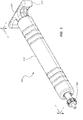
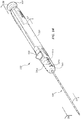
- FIG. 1 is a perspective view of an impact biopsy device 100 in a primed configuration.
- the biopsy device 100 may comprise a body member 110 that may be configured to be grasped by a practitioner when the biopsy device 100 is in use.
- the body member 110 may comprise a handle.
- the biopsy device 100 may also comprise a priming handle 120.
- displacement of the priming handle 120 with respect to the body member 110 may be configured to prime the biopsy device 100.
- the biopsy device 100 may comprise an actuator, such as a trigger 130. Displacement of the trigger 130 with respect to the body member 110 may be configured to actuate elements within the body member 110, such as components of an actuation assembly, in connection with obtaining a tissue sample.
- the biopsy device 100 may comprise an adjustable stop 140. Displacement of the adjustable stop 140 with respect to the body member 110 may be configured to adjust or control the length of the tissue sample severed by the biopsy device 100.
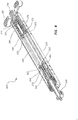
- FIG. 2 is a cross-sectional view of the impact biopsy device 100 of Figure 1 .
- the biopsy device 100 may include an actuation assembly comprised of components configured to displace a needle assembly or other cutting members.
- the actuation assembly refers generally to components configured to transfer energy to cutting members coupled to the biopsy device 100.
- no cutting members are coupled to the biopsy device 100. It is within the scope of this disclosure to couple any variety of needles, cannula, trocars, stylets, or other instruments to the biopsy device 100.
- a stylet and cannula configured to sever a partial core tissue sample may be operably coupled to the biopsy device 100.
- one or more cannula configured to obtain a full core tissue sample may be operably coupled to the biopsy device 100.
- one or more elements of a needle or cutting assembly may be coupled to components within the body member 110 of the biopsy device 100 and may extend from the body member 110 through an adjustable stop lumen 145.
- the biopsy device 100 is disposed in a primed configuration, meaning the biopsy device 100 is disposed in a configuration from which it can be actuated.
- the biopsy device 100 may comprise a biasing element, such as a spring 190.
- the spring 190 may be loaded such that potential energy is stored within the spring 190.
- the biopsy device 100 is ready to be actuated.
- the biopsy device 100 may comprise a second biasing element, such as a trigger return spring 132, as further detailed below.
- the biopsy device 100 may comprise a traveler 150 disposed within the body member 110.
- the spring 190 is disposed around a shaft 154 of the traveler 150.
- the traveler 150 may be disposed such that the spring 190 exerts a force on the traveler 150.
- the traveler 150 may be positioned such that the position of the traveler 150 compresses or loads the spring 190 between a flange 152 of the traveler 150 and a load surface 186 of a retention tube 180.
- Proximal catches 182 of the retention tube 180 may contact the flange 152 of the traveler 150 such that the proximal catches 182 maintain the position of the traveler 150 with respect to the retention tube 180 when the biopsy device 100 is in the primed configuration.
- the spring 190 may exert a distally oriented force on the flange 152 of the traveler 150 that, in turn, exerts a distally oriented force on the proximal catches 182.
- a proximally oriented force, exerted on traveler flange 152 by the proximal catches 182, maintains the relative position of the traveler 150 with respect to the retention tube 180.
- the retention tube 180 may be fixedly coupled to the body member 110, including embodiments wherein the retention tube 180 and body member 110 are integrally formed as a single part.
- the embodiment of Figure 2 further comprises an impact member 160 that may have a flange 162 and an extension 164. Distal catches 184 of the retention tube 180 may contact the impact member flange 162 preventing the impact member 160 from being displaced in a distal direction.
- a follower 170 may be coupled to the impact member 160 such that distal displacement of the impact member 160 causes distal displacement of the follower 170.
- the impact member 160 and follower 170 may each be coupled to cutting components configured to extend through the adjustable stop lumen 145 such that displacement of the impact member 160 and follower 170 displace the coupled cutting components.
- Figure 3 is a perspective view of the impact biopsy device 100 of Figure 1 in an actuated configuration.
- Figure 4 is a cross-sectional view of the impact biopsy device 100 of Figure 3 , in the same actuated configuration. Referring to both of these Figures, the body member 110, priming handle 120, and adjustable stop 140 are shown.
- the trigger 130 is displaced distally as compared to the primed configuration on Figures 1 and 2 .
- the biopsy device 100 may be configured such that displacement of the trigger 130 releases the actuation mechanism of the biopsy device 100, thus displacing cutting elements that may be coupled to the biopsy device 100.
- the trigger 130 may interact with the proximal catches 182 and distal catches 184 of the retention tube 180 such that distal displacement of the trigger 130 with respect to the retention tube 180 causes the proximal catches 182 and distal catches 184 to move out of contact with the traveler flange 152 and impact member flange 162, respectively.
- the spring 190 may displace the traveler 150 in a distal direction.
- Figure 4 illustrates the components of the biopsy device 100 at the instant the proximal catches 182 have moved out of contact with the traveler flange 152 in response to displacement of the trigger 130, but before the traveler 150 is displaced by the spring 190.
- the traveler 150 may then move distally until it impacts the impact member 160, the follower 170, or both. As the distal catches 184 are not in contact with the impact member flange 162 in the actuated configuration, such an impact may cause distal displacement of the impact member 160. Also as detailed below, distal displacement of the impact member 160 may cause distal displacement of the follower 170. Additionally, displacement of the trigger 130 in a distal direction may compress the trigger return spring 132, as shown in Figure 4 .
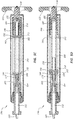
- Figure 5A is a cross-sectional view of the impact biopsy device 100 of Figure 1 in a first configuration.
- the impact biopsy device 100 is in the primed configuration.
- the spring 190 is loaded, with potential energy stored in the compressed spring 190.
- other energy sources such as compressed gas, may be used in connection with, or in place of, a compressed spring 190.
- the proximal catches 182 are engaged with the traveler flange 152 securing the position of the traveler 150 with respect to the retention tube 180.
- the distal catches 184 are engaged with the impact member flange 162.
- the trigger 130 is disposed such that distal displacement of the trigger 130 would actuate the biopsy device 100.
- the priming handle 120 is also shown in this view.
- the adjustable stop 140 may comprise threads 146 configured to allow a user to displace the adjustable stop 140 with respect to the retention tube 180 of the biopsy device 100.
- the adjustable stop threads 146 are engaged with threads 185 on the retention tube 180.
- rotation of the adjustable stop 140 with respect to the retention tube 180 may proximally or distally displace adjustable stop 140 with respect to the retention tube 180.
- mechanisms or features other than threads may be configured to allow a user to displace the adjustable stop 140 with respect to the retention tube 180. For example, detents, notches, cams, and so forth may be used.
- Figure 5B is a cross-sectional view of the impact biopsy device 100 of Figure 1 in a second configuration.
- the biopsy device 100 is in the primed configuration, as in Figure 5A .
- the adjustable stop 140 has been distally displaced as compared to the configuration of Figure 5A .
- displacement of the adjustable stop 140 may be configured to control the length of tissue sample severed by the biopsy device 100.
- movement of impact member 160 and follower 170 may be controlled by the position of the adjustable stop 140.
- the impact member 160 and follower 170 may be displaced distally due to impact with the traveler 150 until one or both of the impact member 160 and follower 170 contact the adjustable stop 140.
- the position of the impact member 160 and follower 170 may be determined by the distal catches 184 coupled to the retention tube 180, as shown in Figures 5A and 5B .
- the length of travel of the impact member 160 and follower 170 (and the cutting members coupled thereto) may be adjusted by displacement of the adjustable stop 140 with respect to the retention tube 180.
- Interaction of the adjustable stop threads 146 and the retention tube threads 185 may be configured to make the adjustable stop 140 adjustable along a continuous range over which the threads 146, 185 are engaged.
- the adjustable stop 140 may be configured such that a practitioner can adjust the length of the sample to be severed by the biopsy device 100, at any relative position along the adjustable path of the adjustable stop 140.
- An adjustable stop 140 may facilitate use of the biopsy device 100 in particular therapies or procedures.
- the adjustable stop 140 may be adjustable over a continuous range, allowing a practitioner to configure the biopsy device 100 to sever a sample of any length within the range. For example, a practitioner may desire to sever a relatively short tissue sample, such as instances where obtaining a deeper sample would cause unwanted trauma to adjacent tissue. Thus, the practitioner may manipulate the position of the adjustable stop 140 in order to obtain a sample of a desired length while avoiding severing tissue adjacent the sample.
- Embodiments that utilize distinct catches to position the adjustable stop 140 at particular intervals are also within the scope of this disclosure.
- the adjustable stop 140 may be adjustable over a continuous range of any length.
- the adjustable stop 140 may be configured to allow a practitioner to adjust sample length over a continuous range from 2 mm to 35 mm, including from 5 mm to 30 mm, and from 10 mm to 20 mm. Further, the sample length may be adjustable to lengths less than 2 mm or greater than 35 mm.
- the impact member 160 is engaged with the distal catches 184 of the retention tube 180, the follower 170 is engaged with the impact member 160, the spring 190 is loaded, and the traveler 150 is engaged with the proximal catches 182.
- the trigger 130 is disposed in the ready to actuate position, with the trigger return spring 132 uncompressed.
- the priming handle 120 is shown in the same relative position as in Figure 5A .
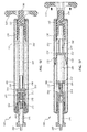
- Figure 5C is a cross-sectional view of the impact biopsy device 100 of Figure 1 in a third configuration.
- the biopsy device 100 has been actuated by distal displacement of the trigger 130 as compared to the primed configuration of Figures 5A and 5B .
- the arrow in Figure 5C indicates the displacement of the trigger 130.
- the biopsy device 100 may be configured such that a practitioner may depress the trigger 130 in a distal direction to actuate the biopsy device 100.
- Other types of triggers or actuators such as handles, levers, sliders, and so forth, are likewise within the scope of this disclosure.
- actuation of the trigger 130 may be configured to release the actuation mechanism of the biopsy device 100 such that cutting members coupled to the device are displaced to sever a tissue sample.
- distal displacement of the trigger 130 moves the proximal catches 182 out of engagement with the traveler flange 152 and the distal catches 184 out of engagement with the impact member flange 162.
- the components of Figure 5C are illustrated with the catches 182, 184 moved out of engagement, but before the other elements of the actuation mechanism (such that the spring 190, traveler 150, impact member 160, and follower 170) are displaced.
- the spring 190 is still compressed; however, the proximal catches 182 are no longer restraining the traveler 150.
- the elements are shown at the instant the spring 190 begins to accelerate and displace the traveler 150.
- the adjustable stop 140 is shown in the same position relative to the retention tube 180 as in Figure 5B . Also, the priming handle 120 is shown in the same relative position as that shown in Figures 5A and 5B .
- Figure 5D is a cross-sectional view of the impact biopsy device 100 of Figure 1 in a fourth configuration.
- the spring 190 has displaced the traveler 150 in the distal direction.
- the spring 190 may exert a force separating the traveler 150 from the loading surface 186 of the retention tube 180. This force may displace the traveler 150 in the distal direction, in some instances converting at least a portion of the potential energy stored in the spring 190 to kinetic energy associated with the traveler 150.
- the traveler 150 may move distally until it impacts the impact member 160.
- the traveler 150 is shown at the moment it impacts the impact member 160, before the impact member 160 is displaced due to the contact.
- the trigger 130 is depressed distally, the distal catches 184 are moved out of engagement with the impact member 160, allowing the impact member 160 to be displaced due to contact with the traveler 150.
- the trigger 130 is depressed distally and the trigger return spring 132 compressed.
- the trigger return spring 132 may be configured to return the trigger 130 proximally after a user actuates the biopsy device 100.
- the displacement of the actuation elements as depicted in Figures 5B-5E may be completed very quickly, the trigger 130 is still shown as depressed distally in the views of Figures 5B-5D .
- the displacement of the actuation mechanism components may be complete before a practitioner removes his or her finger from the trigger 130 once the trigger 130 is actuated.
- the spring 190 is shown as expanding such that it remains in contact with the traveler 150 when the traveler 150 impacts the impact member 160. In other embodiments, the spring 190 may be shorter, such that the spring 190 does not maintain contact with the traveler 150 along the entire displacement of the traveler 150 between the primed position and the impact position.
- FIG. 5E is a cross-sectional view of the impact biopsy device 100 of Figure 1 in a fifth configuration, with the impact member 160 and follower 170 displaced distally as compared to the configuration of Figure 5D .
- the traveler 150 may impact the impact member 160 and transfer all, or a substantial portion, of the kinetic energy associated with the traveler 150 to the impact member 160. Thus, after impact, the traveler 150 may remain in essentially the same relative position as that at which impact was made. In some embodiments, the traveler 150 may additionally or alternatively move slightly distally or proximally after impact, may stay in contact with the impact member 160 as the impact member 160 is displaced, or may continue to move distally though at a different rate than the impact member 160. In other embodiments, the traveler 150 may first impact the follower 170 and the impact member 160 may accelerate due to interaction with the follower 170. Still further, in some embodiments, the traveler 150 may be configured to impact both the impact member 160 and the follower 170.
- the impact member 160 may be displaced distally after impact, moving until it contacts the adjustable stop 140.
- Contact with the adjustable stop 140 may be configured to stop the movement of the impact member 160 and, as further detailed below, stop the tissue severing of a cutting member associated with the impact member 160.
- the follower 170 may be configured to initially be displaced with the impact member 160. In some instances, the follower 170 may be decoupled from the impact member 160 before the impact member 160 reaches the adjustable stop 140, which may cause the follower 170 to stop at a different position or at a different time than the impact member 160.
- interaction between the follower 170 and the adjustable stop 140 may stop the displacement of the follower 170 at a position proximal to a position at which the adjustable stop 140 stops the impact member 160.
- the impact member 160 has moved to the end of its travel path distally, such that the impact member 160 is in contact with the adjustable stop 140.
- the follower 170 is shown in a relatively more proximal position with respect to the impact member 160 as compared to the position of the follower 170 with respect to the impact member 160 in the configuration of Figure 5D (though both elements have been moved distally with respect to the retention tube 180 between the configurations of Figure 5D and Figure 5E ).
- this offset between the travel distance of the impact member 160 and the follower 170 may be configured to displace cutting members associated with each component such that the cutting members fully sever a tissue sample from the patient.
- the trigger return spring 132 is shown in an expanded configuration, with the trigger 130 returned proximally to the same position as when the trigger 130 is in the primed configuration.
- the trigger return spring 132 may be configured to return the trigger 130 to this position after a practitioner actuates the biopsy device 100. Again, the displacement of components within the biopsy device 100 may be configured to take place sufficiently rapidly that the biopsy device 100 is fully actuated before a practitioner removes his or her finger from the trigger 130 after initially activating the biopsy device 100.
- the proximal catches 182 and distal catches 184 may return to a position within the travel paths of the traveler 150 and impact member 160, respectively. However, because the traveler 150 and impact member 160 have been distally displaced, the catches 182, 184 are not engaged with the traveler 150 and impact member 160 in this configuration.
- the priming handle 120 is also shown in the view of Figure 5E . Priming catches 122 are also indicated.
- Figure 5F is a cross-sectional view of the impact biopsy device 100 in a sixth configuration, showing the actuation mechanism partially returned to a primed configuration.
- the biopsy device 100 may comprise a priming handle 120 configured to return the actuation mechanism to a primed configuration.
- proximal displacement of the priming handle 120 with respect to the retention tube 180 may proximally displace the priming catches 122.
- the priming catches 122 may then interact with the impact member flange 162, drawing the impact member 160 proximally as the priming handle 120 is moved proximally.
- the impact member 160 may reengage the follower 170 as the impact member 160 is moved proximally, moving the follower 170 proximally.
- the distal catches 184 may engage the impact member flange 162 and the priming catches 122 may disengage from the impact member flange 162.
- the impact member 160 and follower 170 are shown returned to the primed position.
- the priming catches 122 may then engage the traveler flange 152, proximally displacing the traveler 150 such that the spring 190 is compressed and the traveler 150 returns to engagement with the proximal catches 182.
- the priming handle 120 may be returned distally to the position shown in Figure 5A .
- displacement of the priming handle 120 may be configured to also return the trigger 130 to a prime position, including embodiments that comprise no trigger return spring 132.
- embodiments wherein the priming handle 120 and trigger 130 are fixedly coupled, comprising a single element configured to both actuate and prime the biopsy device 100, are within the scope of this disclosure.
- a cutting member may not actually sever tissue unless the cutting member is moving at a sufficient speed or has a sufficient force acting thereon.
- placing a cutting member in contact with tissue to be biopsied, then directly accelerating the cutting member through contact with a spring may crush or deform a proximal end of the tissue sample as the cutting member is accelerated to cutting speed.
- a device that utilizes direct acceleration of a cutting member by a spring may displace the cutting member an amount before the cutting member reaches cutting speed. The proximal end of the tissue sample may be deformed or crushed during this acceleration.
- such devices may utilize springs with very high spring constants in order to accelerate the cutting member as quickly (and over as short a distance) as possible. Such springs may make an associated device difficult to prime or use, and may create vibrations, noises, or other issues when the device is actuated.
- An impact biopsy device such as impact biopsy device 100 of Figures 5A-5F , may be configured to quickly transfer force to a cutting member, and thus may be configured to limit deformation of the tissue sample during cutting.
- the biopsy device 100 may first accelerate the traveler 150, allowing the traveler to reach a particular speed before any cutting members are displaced.
- the spring 190 may be configured to accelerate the traveler 150 to an impact speed over a distance (such as the distance the traveler is displaced prior to impact) that may allow use of a spring having a relatively small spring constant, as the traveler is not required to reach impact speed prior to impact with the impact member 160.
- the "impact speed" of the traveler 150 may be defined as the speed at which the traveler 150 travels in order to impart an impact force sufficient to accelerate the impact member 160 to cutting speed.
- an impact biopsy device may facilitate severing tissue samples of a variety of lengths.
- the impact configuration may accelerate cutting members associated with the device to cutting speed without substantially displacing the cutting members.
- the impact biopsy device may accelerate the traveler 150 over a distance, but the transferred force to the impact member 160 (then to any related cutting members) may not involve acceleration of these members over a distance.
- an impact biopsy device may be configured to sever particularly short samples, as the cutting members reach cutting speed without substantial displacement.
- direct acceleration of a cutting member by a spring may require some displacement of the cutting member before the cutting member reaches cutting speed.
- the minimum sample length may be at least as long as the displacement needed to bring such a cutting member to cutting speed.
- an impact biopsy device may be configured such that the cutting members maintain a substantially uniform cutting speed during the severing of an entire sample, rather than accelerating during the first portion of the severing. Samples severed by uniform cutting speeds may be generally more uniform than samples severed by accelerating cutting members, which may deform a portion of the sample.
- the exponential factor associated with the potential energy of the spring 190 may also facilitate use of springs with relatively small spring constants in the impact biopsy device 100 of Figures 5A-5F .
- Accelerating the impact member 160 and follower 170 through an impact force supplied by an already moving traveler 150 may quickly accelerate the impact member 160 and follower 170 (and the associated cutting members), allowing the cutting members to begin severing tissue without initially deforming the tissue.
- the biopsy device 100 may be configured such that no cutting member is directly coupled to the traveler 150.
- the biopsy device 100 may be configured such that the spring 190, or any other biasing or energy storage element or system, does not directly exert force on any component coupled directly to a cutting member. Rather, the spring 190, or any other biasing or energy storage element or system, may exert a force to accelerate an intermediate component, such as the traveler 150, which in turn exerts a force on components directly coupled to cutting members, such as the impact member 160 and/or follower 170.
- a practitioner may utilize the impact biopsy device 100 in a variety of procedures.
- the practitioner may adjust the adjustable stop 140 to any desired point along the continuously adjustable displacement of the adjustable stop 140 to control the length of tissue sample obtained.
- the practitioner may then advance the device within a patient such that cutting members associated with the biopsy device 100 are adjacent tissue to be biopsied.
- a practitioner may adjust the adjustable stop 140 after first advancing the cutting members.
- the practitioner may then actuate the biopsy device 100 by distally displacing the trigger 130. Displacement of the trigger 130 may then release the traveler 150 such that the traveler is accelerated by the spring 190. The traveler 150 may then impact the impact member 160 and follower 170 such that cutting members associated therewith are likewise accelerated. The cutting members may sever a tissue sample, allowing the device to be withdrawn from the patient and the sample obtained.
- FIG 6 is an exploded view of the impact biopsy device 100 of Figure 1 . Below, certain features of the biopsy device 100 and its components are further discussed in connection with this exploded view.
- the exploded view illustrates the body member 110, the retaining tube 180, and the trigger 130 of the biopsy device 100.
- the trigger 130 may comprise grooves or ridges 131 configured to interact with protrusions 181, 183 on the proximal 182 and distal 184 catches. Distal displacement of the trigger 130 may cause the ridges 131 to interact with the protrusions 181, 183 such that the proximal 182 and distal 184 catches are pushed apart, thereby separating opposing catches and moving the catches out of engagement with the traveler flange 152 and impact member flange 162.
- the follower 170 may comprise follower catches 175 configured to couple the follower 170 to the impact member 160.
- the follower catches 175 may be disposed over the impact member 160 such that the follower catches 175 engage impact member protrusions 165. This interaction may cause the follower 170 to be displaced distally when the impact member 160 is so displaced.
- the adjustable stop 140 may comprise a chamfer 142 configured to interact with the follower catches 175.
- the follower catches 175 may contact the chamfer 142 such that the follower catches 175 are spread apart and the follower 170 disengages from the impact member 160. In some embodiments, this interaction may also stop the displacement of the follower 170.
- the impact member 160 may travel distally beyond the point of disengagement with the follower 170 after the follower catches 175 contact the chamfer 142. Thus, in some instances the impact member 160 may be displaced beyond the follower 170 when the biopsy device 100 is actuated.
- Relative positions of the traveler 150 and spring 190 are also shown in the illustrated embodiment. Additionally, the primer handle 120 and primer catches 125 are illustrated.
- Figure 7 is a cross-sectional view of another embodiment of an impact biopsy device 200.
- the embodiment of Figure 7 may include components that resemble components of the embodiment of Figures 1-6 in some respects.
- the embodiment of Figure 7 comprises a body member 210 that may be analogous to the body member 110 of the embodiment of Figures 1-6 .
- all the illustrated embodiments have analogous features and components. Accordingly, like or analogous features are designated with like reference numerals, with the leading digits incremented to "2.” Relevant disclosure set forth above regarding similarly identified features thus may not be repeated hereafter.
- specific features of the device and related components shown in Figure 7 may not be shown or identified by a reference numeral in the drawings or specifically discussed in the written description that follows.
- the impact biopsy device 200 of Figure 7 comprises cutting members (202, 204, 206) coupled to the actuation mechanism.
- the biopsy device 200 comprises a stylet 202 that extends along a central axis of the biopsy device 200 and is coupled to a retention tube 280 adjacent a loading surface 286 of the retention tube 280.
- various components of the actuation mechanism may be configured to accommodate the stylet 202, while still configured to displace as described in connection with the embodiment of Figures 1-6 .
- the stylet 202 may be disposed such that openings or central lumens of a traveler 250, impact member 260, follower 270, and adjustable stop 240 allow these components to move along the length of the stylet 202.
- the stylet 202 extends from the loading surface 286 of the retention tube 280 through the adjustable stop lumen 245 to the outside of the body member 210.
- the biopsy device 200 may be configured such that the retention tube 280 does not move with respect to the body member 210 when the device is actuated. Further, the stylet 202 may be fixedly coupled to the retention tube 280. Thus, in some instances a practitioner may grasp the body member 210, using it as a handle, to advance the stylet 202 to a position within a patient's body as part of a procedure.
- the biopsy device 200 further comprises a cannula 204 coupled to the follower 270 and an outer tubular member 206 coupled to the impact member 260.
- proximal catches 282 may release the traveler 250, allowing it to accelerate and impact the impact member 260.
- the impact member 260 and follower 270 may then displace distally, which, in turn, displaces the outer tubular member 206 and cannula 204 distally.
- a biopsy device may be configured such that the impact member 260 travels a longer distance than the follower 270 when the device is actuated. Accordingly, in some embodiments the cutting member coupled to the impact member 260 (the outer tubular member 206 in the embodiment of Figure 7 ) may be displaced over a longer distance than the cutting member coupled to the follower 270 (the cannula 204 in the embodiment of Figure 7 ). Elements of the actuation assembly coupled to cutting members of the embodiment of Figure 7 are further discussed in connection with Figures 8A-8E , below.
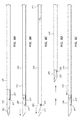
- Figures 8A-8E are side views of a portion of the impact biopsy device 200 of Figure 7 in five different configurations.
- Figures 8A-8E illustrate an example of how the cutting members may be displaced when the biopsy device is actuated.
- the disclosure below, referencing Figures 8A-8E may also reference elements of the biopsy device 200 shown in Figure 7 , but not shown in the views of Figures 8A-8E .
- the stylet 202 extends from the cannula 204 and the outer tubular member 206 is disposed around the cannula 204.
- a cutting element 207 coupled to the outer tubular member 206 is shown disposed proximally of a notch 205 in the cannula 204.
- These members may be disposed as shown in Figure 8A when the biopsy device 200 is in a primed configuration. In this configuration, a practitioner may advance the cutting members to a position within the body adjacent tissue to be biopsied.
- the stylet 202 may be configured with a sharp distal end to facilitate advancement of the cutting members through body tissue, including percutaneous access.
- the cannula 204 and outer tubular member 206 are being displaced distally with respect to the stylet 202.
- the traveler 250 may impact the impact member 260, causing the impact member 260 to be displaced distally.
- the follower 270 may be coupled to the impact member 260 along a portion of this displacement.
- the outer tubular member 206, coupled to the impact member 260, and the cannula 204, coupled to the follower 270 may be simultaneous displaced when the biopsy device 200 is actuated.
- the follower 270 is coupled to the impact member 260, the position of the cannula 204 with respect to the outer tubular member 206 may not change.
- Figure 8C illustrates the cutting members after the follower 270 is disengaged from the impact member 260.
- the biopsy impact device 200 may be configured such that the impact member 260 is displaced over a longer distance than the follower 270 when the biopsy device 200 is actuated.
- the outer tubular member 206 may be distally advanced with respect to the cannula 204. This displacement may cause the cutting element 207 to interact with the notch 205 such that the cutting element 207 passes through the notch 205 into the interior of the cannula 204.
- FIGs 8B and 8C illustrate how the cutting members may sever a tissue sample from the body.
- a distal end of the cannula 204 may sever the longitudinal length of a tissue sample.
- Advancement of the outer tubular member 206 with respect to the cannula 204 may then cause the cutting element 207 to sever the distal end of the tissue sample.
- the tissue sample may then be disposed within the cannula 204 between the cutting member 207 and the distal end of the stylet 202, in the configuration shown in Figure 8C .
- adjustment of the adjustable stop 240 may control the length of travel of the impact member 260 and follower 270.
- the adjustable stop 240 may be configured to control the length of the tissue sample severed by the biopsy device 200.
- Figure 8E illustrates the cutting members as the impact biopsy device 200 is primed. Priming draws the cannula 204 and outer tubular member 206 proximally with respect to the stylet 202, removing the cutting element 207 from the notch 205 and forcing the tissue sample out of the cannula 204, due to interaction with the stylet 202.
- each member may be coupled to a particular element of an impact biopsy device actuation mechanism. Further, elements of the mechanism may be configured to allow for desired offsets or relative displacements of cutting members. For example, in the embodiment of Figures 9A-9C , the cutting members may be configured with a larger difference in total displacement than the difference between the total displacement of the cannula 204 and outer tubular member 206 of Figures 8A-8E .
- Figures 9A-9C are side views of another embodiment of a portion of an impact biopsy device. These figures illustrate a stylet 302 and a cannula 304.
- the cutting members may be advanced to a position within the body adjacent tissue to be biopsied in the configuration shown in Figure 9A .
- the stylet 302 may extend from the cannula 304, exposing a trough 303 in the stylet 302, as shown in Figure 9B . Tissue may then prolapse into the trough 303, filling the void of the trough 303.
- Advancement of the cannula 304 may sever the length and end of the tissue within the trough 303, severing a tissue sample from the body.
- the cannula 304 and stylet 302 may then be withdrawn to retrieve the tissue sample.
- the cannula 304 and stylet 302 may be coupled to elements of an impact biopsy device configured to displace the cannula 304 and stylet 302 as shown.
- FIGS 10-13 illustrate another embodiment of an impact biopsy device 400 in a primed configuration.
- This biopsy device 400 is analogous to the other biopsy devices disclosed herein.
- the biopsy device 400 comprises a traveler 450, impact member 460, and follower 470. While these components function in an analogous manner to similarly named components of other embodiments disclosed herein, certain distinctions with respect to each member are outlined below in connection with Figures 10-13 .
- the biopsy device 400 comprises a body member 410 that may be configured to be grasped by a practitioner when the biopsy device 400 is in use.
- the body member 110 may comprise a handle.
- the biopsy device 400 further comprises a priming handle 420.
- the priming handle 420 comprises an end input 422 and a longitudinal input 424.
- either the end input 422 and the longitudinal input 424 may be utilized by a user to prime the biopsy device 400.
- Proximal displacement of the priming handle 420 is configured to prime the biopsy device 400.
- proximal displacement of either the end input 422 or the longitudinal input 424 may proximally displace the priming handle 420.
- the biopsy device 400 further comprises an adjustable stop 440.
- Indicia 441 on the adjustable stop may be configured to relate the rotational position of the adjustable stop 440 with the longitudinal displacement of one or more components of the biopsy device 400.
- Figure 11 is a cross-sectional view, taken through plane 11, of the impact biopsy device 400 of Figure 10 ;
- Figure 12 is a cross-sectional view, taken through plane 12, of the impact biopsy device 400 of Figure 10 ;
- Figure 13 is an exploded view of the impact biopsy device 400 of Figure 10 .
- the biopsy device 400 may comprise a traveler 450, an impact member 460, and a follower 470.
- displacement of the traveler 450, impact member 460, and follower 470 may be configured to displace one or more cutting members, for example biopsy needles, during a procedure.
- the biopsy device 400 may comprise a biasing member such as spring 490.
- the spring 490 may be at least partially compressed such that potential energy is stored in the spring 490.
- the traveler 450, impact member 460, and follower 470 may each be disposed at the proximal-most points of each components' path of travel during operation.
- the traveler 450 in the primed configuration, is disposed such that traveler catches 455 of the traveler 450 are engaged with proximal catches 482 of a retention tube 480 of the biopsy device 400. Similarly, impact member catches 464 of the impact member 460 are engaged with distal catches 484 of the retention tube 480.
- the spring 490 is compressed between the traveler 450 and a proximal end of the retention tube 480.
- the traveler 450 is thus longitudinally offset from the impact member 460 such that upon actuation of the device, the traveler 450 moves longitudinally along this offset before contacting the impact member 460.
- follower catches 475 of the follower 470 are engaged with a distal edge 465 of the impact member 460. Due to this interaction, when the impact member 460 is initially displaced distally during actuation of the biopsy device 400, the follower 470 is also displaced, maintaining the same position with respect to the impact member 460.
- priming the biopsy device 400 may comprise proximal displacement of the priming handle 420 with respect to the retention tube 480. Such displacement may be the result of user input at the end input 422, the longitudinal input 424, or both.
- primer catches 425a adjacent a distal end of the priming handle 420 may engage a distal edge 465 of the impact member 460.
- proximal displacement of the priming handle 420 may simultaneously proximally displace the impact member 460 when the primer catches 425a and the distal edge 465 are engaged.
- the follower 470 may be positioned within the impact member 460 such that the follower catches 475 are proximal of an inside edge 468 of the impact member 470.
- the follower 470 is illustrated adjacent the impact member 460. In this arrangement each part can be viewed separately.
- the follower 470 is disposed coaxially with, and within, the impact member 460 such that the radial protrusions 477 that extend from the follower 470 and are coupled to the follower catches 475 extend through side openings 467 in the impact member 460.
- Figures 11 and 12 illustrate these components in an assembled state.
- proximal displacement of the impact member 460 may also proximally displace the follower 470 as the inside edge 468 may act on the follower catches 475.
- the follower catches 475 may slip past the inside edge 468 such that an inside ridge 466 of the impact member 460 engages a slot 476 of the follower 470.
- the follower 470 will be proximally displaced with the impact member 460 during priming.
- proximal displacement of the priming handle 420 during priming may thus proximally displace the impact member 460 and follower 470 until the impact member catches 464 engage the distal catches 484 of the retention tube 480. If the follower catches 475 did not slip distally past the inside edge 468 of the impact member 460, an annular ridge 487 (shown in Figure 12 ) may engage the follower 470, halting its proximal displacement before the impact member 470 is fully at the primed position.
- This annular ridge 487 thus ensures the follower catches 475 will slip past the inside edge 468 of the impact member 460 and that the follower catches 475 will be engaged with the distal edge 465 of the impact member 470 when the biopsy device 400 is in the primed configuration.
- a primer catch 425b engages the traveler 450 to proximally displace the traveler 450 with respect to the retention tube 480.
- This primer catch 425b may comprise a distal end of one or more inside grooves on the inside diameter of the retention tube 480.
- the traveler catches 455 may comprise distal traveler catch shoulders 452 that engage primer catch 425b.
- the traveler 450 may be proximally displaced until the traveler catches 455 engage the proximal catches 482 of the retention tube 480. Proximal displacement of the traveler 450 with respect to the retention tube 480 compresses the spring 490 between the traveler 450 and a proximal end of the retention tube 480.
- the traveler catches 455 are engaged with the proximal catches 482 of the retention tube 480
- the impact member catches 464 are engaged with the distal catches 484 of the retention tube 480
- the follower catches 475 are engaged with the distal edge 465 of the impact member 470
- the biopsy device 400 is primed and ready for use.
- the biopsy device 400 of Figures 10-13 does not comprise a separate trigger (such as 130 of Figure 1 ). Rather, the priming handle 420 of the embodiment of Figures 10-13 may be displaced to actuate the biopsy device 400.
- distal displacement of the priming handle 420 with respect to the retention tube 480 will cause trigger surfaces 432 of the priming handle 420 to displace the traveler catches 455 radially outward. This displacement causes the traveler catches 455 to be out of engagement with the proximal catches 482 of the retention tube 480.
- the spring 490 may expand and force the traveler 450 to be displaced proximally.
- the traveler 450 may then strike the impact member 460, transferring kinetic energy to the impact member 460.
- disengagement surfaces 453 on the traveler 450 may displace the impact member catches 464 radially outward and out of engagement with the distal catches 484 of the retention tube 480.
- the impact member 460 will then be displaced distally due to the transfer of kinetic energy.
- the follower 470 will be distally displaced with the impact member 460 until the follower catches 475 contact a chamfer 442 on the proximal end of a threaded portion 446 of the adjustable stop 440.
- the chamfer 442 forces the follower catches 475 radially outward, out of engagement with the distal edge 465 of the impact member 460 and stops the distal displacement of the follower 470.
- a cutting instrument coupled to the impact member 460 may be configured to travel farther than a cutting instrument coupled to the follower 470.
- the biopsy device 400 may further comprise a safety 438 configured to prevent accidental actuation of the biopsy device 400.
- the safety 438 of the illustrated embodiment comprises a rectangular member that may be transversely displaceable with respect to the body member 410.
- the safety 438 may comprise an opening 439.
- the safety 438 may be configured to prevent distal displacement of the priming handle 420 beyond a safety point due to interference between the safety 438 and a portion of the priming handle 420.
- the biopsy device 400 may be configured such that only proximal displacement of the priming handle 420 beyond the safety point will trigger the biopsy device 400.
- the safety 438 When the safety 438 is positioned such that the opening 439 is aligned with the priming handle 420, the priming handle 420 may be displaced distally beyond the safety point, allowing for actuation of the biopsy device 400.
- the adjustable stop 440 of the biopsy device 400 of Figures 10-13 may comprise a cap portion 444 and a threaded portion 446.
- the cap portion 444 may be coupled to the threaded portion 446 such that rotation of the cap portion 444 causes rotation of the threaded portion 446 while the threaded portion 446 is allowed to displace longitudinally with respect to the cap portion 444.
- a ridge of the threaded portion 446 may be displaced within a slot of the cap portion 444, such that the ridge and slot may transfer rotational displacement of the cap portion 444 without restraining longitudinal displacement of the threaded portion 446.
- indicia 441 on the cap portion 444 correlate with the longitudinal displacement of the threaded portion 446, allowing a practitioner to adjust and/or set the stroke length through rotation of the cap portion 444 and observation of the relative position of the indicia 441, with respect, for example, to the body member 410.
- FIG 14 is a perspective view of another embodiment of an impact biopsy device 500.
- Figure 15 is an exploded view of the impact biopsy device 400 of Figure 14 .
- the biopsy device 500 is analogous to the biopsy device 400 of Figure 10 , and the other embodiments disclosed herein, in many respects.
- the biopsy device 500 comprises a body member 510, priming handle 520, safety 538, adjustable stop 540, traveler 550, impact member 560, follower 570, retention tube 580, and spring 590.
- Each of these elements function in an analogous manner to like elements discussed in connection with the embodiment of Figure 10 .
- the priming handle 520 comprises an end input 522 and a longitudinal input 524 and the adjustable stop 540 comprises a cap portion 544 and a threaded portion 546.
- the priming handle 520 comprises a distal portion 520a and a proximal portion 520b. These portions may be formed separately then coupled during assembly of the biopsy device 500.
- the cap portion 544 of the adjustable stop 540 comprises an opening 543.
- the adjustable stop 540 further comprises indicia 541 a arranged longitudinally along the cap portion 544 as well as a pointer 541b on the threaded portion 546. Rotation of the cap portion 544, and subsequent longitudinal displacement of the threaded portion 546 with respect to the cap portion 544, will displace the pointer 541b with respect to the indicia 541a.
- These indicia may correlate with stroke length, allowing a practitioner to set and adjust stroke length by rotation of the cap portion 544 and reference to the indicia 541a and pointer 541b.
- a cutting member assembly 505 is coupled to the biopsy device 500 of Figures 14 and 15 . Again it is within the scope of this disclosure to use any cutting member or assembly in connection with any handle or triggering mechanism disclosed herein.
Landscapes
- Health & Medical Sciences (AREA)
- Life Sciences & Earth Sciences (AREA)
- Medical Informatics (AREA)
- Engineering & Computer Science (AREA)
- Biomedical Technology (AREA)
- Heart & Thoracic Surgery (AREA)
- Pathology (AREA)
- Molecular Biology (AREA)
- Surgery (AREA)
- Animal Behavior & Ethology (AREA)
- General Health & Medical Sciences (AREA)
- Public Health (AREA)
- Veterinary Medicine (AREA)
- Surgical Instruments (AREA)
Abstract
Description
- This application claims priority to United States Provisional Application No.
61/754,401 filed on January 18, 2013 - The present disclosure relates generally to medical devices. More specifically, the present disclosure relates to biopsy devices, including biopsy devices configured with an impact driven or kinetic energy operation system.
The invention is, in particular, related to biopsy devices and methods according to any of the following statements:
According to statement 1, the invention relates to a tissue biopsy device, comprising: - a handle configured to be grasped by a user;
- a needle assembly operably coupled to the handle, the needle assembly configured to sever a tissue sample; and
- an actuator assembly operably coupled to the handle and needle assembly, the actuator assembly comprising:
a biasing member; - a traveling member configured to be displaced by the biasing member when the actuator assembly is actuated; and
- an impact member coupled to the needle assembly, the impact member configured to displace at least a portion of the needle assembly when the traveling member impacts the impact member.
- a handle configured to be graspable by a user;
- a biasing member operably coupled to the handle, the biasing member configured to store potential energy when the biopsy device is in a primed configuration;
- a traveling member operably coupled to the handle, the traveling member disposed such that the potential energy stored in the biasing member is at least partially converted to kinetic energy associated with the traveling member when the biopsy device is actuated; and
- an impact member operably coupled to the handle and to the biasing member, the device configured such that the traveling member impacts the impact member when the biopsy device is actuated such that the impact member is displaced relative to the handle.
- releasing a traveling member such that the traveling member is displaced a first longitudinal distance along the biopsy device;
- impacting the traveling member with an impact member such that the impact member is displaced a second longitudinal distance along the biopsy device; and displacing a first cutting member coupled to the impact member such that the cutting member severs a first portion of the tissue sample.
- The embodiments disclosed herein will become more fully apparent from the following description and appended claims, taken in conjunction with the accompanying drawings. The drawings depict only typical embodiments, which embodiments will be described with additional specificity and detail in connection with the drawings in which:
-
Figure 1 is a perspective view of an impact biopsy device in a primed configuration. -
Figure 2 is a cross-sectional view of the impact biopsy device ofFigure 1 . -
Figure 3 is a perspective view of the impact biopsy device ofFigure 1 in an actuated configuration. -
Figure 4 is a cross-sectional view of the impact biopsy device ofFigure 3 , in the configuration ofFigure 3 . -
Figure 5A is a cross-sectional view of the impact biopsy device ofFigure 1 in a first configuration. -
Figure 5B is a cross-sectional view of the impact biopsy device ofFigure 1 in a second configuration. -
Figure 5C is a cross-sectional view of the impact biopsy device ofFigure 1 in a third configuration. -
Figure 5D is a cross-sectional view of the impact biopsy device ofFigure 1 in a fourth configuration. -
Figure 5E is a cross-sectional view of the impact biopsy device ofFigure 1 in a fifth configuration. -
Figure 5F is a cross-sectional view of the impact biopsy device ofFigure 1 in a sixth configuration. -
Figure 6 is an exploded view of the impact biopsy device ofFigure 1 . -
Figure 7 is a cross-sectional view of another embodiment of an impact biopsy device. -
Figure 8A is a side view of a portion of the impact biopsy device ofFigure 7 in a first configuration. -
Figure 8B is a side view of a portion of the impact biopsy device ofFigure 7 in a second configuration. -
Figure 8C is a side view of a portion of the impact biopsy device ofFigure 7 in a third configuration. -
Figure 8D is a side view of a portion of the impact biopsy device ofFigure 7 in a fourth configuration. -
Figure 8E is a side view of a portion of the impact biopsy device ofFigure 7 in a fifth configuration. -
Figure 9A is a side view of another embodiment of a portion of an impact biopsy device in a first configuration. -
Figure 9B is a side view of a portion of the impact biopsy device ofFigure 9A in a second configuration. -
Figure 9C is a side view of a portion of the impact biopsy device ofFigure 9A in a third configuration. -
Figure 10 is a perspective view of another embodiment of an impact biopsy device in a primed configuration. -
Figure 11 is a cross-sectional view, taken throughplane 11, of the impact biopsy device ofFigure 10 . -
Figure 12 is a cross-sectional view, taken throughplane 12, of the impact biopsy device ofFigure 10 . -
Figure 13 is an exploded view of the impact biopsy device ofFigure 10 . -
Figure 14 is a perspective view of another embodiment of an impact biopsy device. -
Figure 15 is an exploded view of the impact biopsy device ofFigure 14 . - Biopsy devices may be configured to retrieve tissue samples from various locations within a patient's body. For example, a biopsy device may comprise a needle assembly including cannula or other cutting members configured to sever a tissue sample. The needle assembly may be advanced to a location within the body through the skin of the patient (percutaneous access) or may be advanced through a body lumen or other structure.
- Furthermore, a biopsy device may comprise an actuation mechanism configured to displace the needle assembly such that the needle assembly severs the targeted tissue sample. Biasing mechanisms such as springs, triggers, and so forth may be configured to allow a practitioner to manipulate various components of a needle assembly through manipulating the actuation mechanism. In addition to mechanical biasing mechanisms such as springs, compressed gas or other energy sources may be configured to power a biopsy device. In some embodiments, for example, a compressed CO2 cartridge may be used to power a biopsy device.
- Regardless of the energy source, a mechanism may be configured such that, once the needle assembly is disposed adjacent tissue to be biopsied, actuation of a single trigger may cause various components of a needle assembly to be displaced to sever a tissue sample. Biasing elements or other energy sources within the actuation mechanism may provide the force required to advance the needle assembly components, and other mechanisms may control the relative displacement of individual components of a needle assembly.
- As further disclosed below, a biopsy device may comprise components configured to actuate the biopsy device through transfer of kinetic energy between components, including instances where one or more components are displaced due to an impact force.
- It will be readily understood that the components of the embodiments as generally described and illustrated in the Figures herein could be arranged and designed in a wide variety of different configurations. Thus, the following more detailed description of various embodiments, as represented in the Figures, is not intended to limit the scope of the disclosure, but is merely representative of various embodiments. While the various aspects of the embodiments are presented in drawings, the drawings are not necessarily drawn to scale unless specifically indicated.
- The phrases "connected to" and "coupled to" refer to any form of interaction between two or more entities, including mechanical, electrical, magnetic, electromagnetic, fluid, and thermal interaction. Two components may be coupled to each other even though they are not in direct contact with each other. For example, two components may be coupled to each other through an intermediate component.
- The directional terms "proximal" and "distal" are used herein to refer to opposite locations on a medical device. The proximal end of the device is defined as the end of the device closest to the practitioner when the device is in use by the practitioner. The distal end is the end opposite the proximal end, along the longitudinal direction of the device, or the end furthest from the practitioner.
-
Figure 1 is a perspective view of animpact biopsy device 100 in a primed configuration. Thebiopsy device 100 may comprise abody member 110 that may be configured to be grasped by a practitioner when thebiopsy device 100 is in use. Thus, in some embodiments thebody member 110 may comprise a handle. Thebiopsy device 100 may also comprise apriming handle 120. As further discussed below, displacement of the priming handle 120 with respect to thebody member 110 may be configured to prime thebiopsy device 100. Similarly, thebiopsy device 100 may comprise an actuator, such as atrigger 130. Displacement of thetrigger 130 with respect to thebody member 110 may be configured to actuate elements within thebody member 110, such as components of an actuation assembly, in connection with obtaining a tissue sample. - Additionally, the
biopsy device 100 may comprise anadjustable stop 140. Displacement of theadjustable stop 140 with respect to thebody member 110 may be configured to adjust or control the length of the tissue sample severed by thebiopsy device 100. -
Figure 2 is a cross-sectional view of theimpact biopsy device 100 ofFigure 1 . As shown inFigure 2 , thebiopsy device 100 may include an actuation assembly comprised of components configured to displace a needle assembly or other cutting members. As used herein the actuation assembly refers generally to components configured to transfer energy to cutting members coupled to thebiopsy device 100. - In the embodiment of
Figures 1 and2 , no cutting members are coupled to thebiopsy device 100. It is within the scope of this disclosure to couple any variety of needles, cannula, trocars, stylets, or other instruments to thebiopsy device 100. For example, a stylet and cannula configured to sever a partial core tissue sample may be operably coupled to thebiopsy device 100. Further, one or more cannula configured to obtain a full core tissue sample may be operably coupled to thebiopsy device 100. In some embodiments, one or more elements of a needle or cutting assembly may be coupled to components within thebody member 110 of thebiopsy device 100 and may extend from thebody member 110 through anadjustable stop lumen 145. - In the embodiment of
Figures 1 and2 , thebiopsy device 100 is disposed in a primed configuration, meaning thebiopsy device 100 is disposed in a configuration from which it can be actuated. For example, thebiopsy device 100 may comprise a biasing element, such as aspring 190. In the primed configuration, thespring 190 may be loaded such that potential energy is stored within thespring 190. When in the primed configuration, thebiopsy device 100 is ready to be actuated. Thebiopsy device 100 may comprise a second biasing element, such as atrigger return spring 132, as further detailed below. - The
biopsy device 100 may comprise atraveler 150 disposed within thebody member 110. In the illustrated embodiment, thespring 190 is disposed around ashaft 154 of thetraveler 150. In the primed configuration shown inFigure 2 , thetraveler 150 may be disposed such that thespring 190 exerts a force on thetraveler 150. In other words, thetraveler 150 may be positioned such that the position of thetraveler 150 compresses or loads thespring 190 between aflange 152 of thetraveler 150 and aload surface 186 of aretention tube 180. Proximal catches 182 of theretention tube 180 may contact theflange 152 of thetraveler 150 such that theproximal catches 182 maintain the position of thetraveler 150 with respect to theretention tube 180 when thebiopsy device 100 is in the primed configuration. Thus, in the configuration ofFigure 2 , thespring 190 may exert a distally oriented force on theflange 152 of thetraveler 150 that, in turn, exerts a distally oriented force on the proximal catches 182. A proximally oriented force, exerted ontraveler flange 152 by theproximal catches 182, maintains the relative position of thetraveler 150 with respect to theretention tube 180. In some embodiments, theretention tube 180 may be fixedly coupled to thebody member 110, including embodiments wherein theretention tube 180 andbody member 110 are integrally formed as a single part. - The embodiment of
Figure 2 further comprises animpact member 160 that may have aflange 162 and anextension 164. Distal catches 184 of theretention tube 180 may contact theimpact member flange 162 preventing theimpact member 160 from being displaced in a distal direction. Afollower 170 may be coupled to theimpact member 160 such that distal displacement of theimpact member 160 causes distal displacement of thefollower 170. As further described herein, theimpact member 160 andfollower 170 may each be coupled to cutting components configured to extend through theadjustable stop lumen 145 such that displacement of theimpact member 160 andfollower 170 displace the coupled cutting components. -
Figure 3 is a perspective view of theimpact biopsy device 100 ofFigure 1 in an actuated configuration.Figure 4 is a cross-sectional view of theimpact biopsy device 100 ofFigure 3 , in the same actuated configuration. Referring to both of these Figures, thebody member 110, priminghandle 120, andadjustable stop 140 are shown. In the configuration ofFigures 3 and4 , thetrigger 130 is displaced distally as compared to the primed configuration onFigures 1 and2 . As further explained below, thebiopsy device 100 may be configured such that displacement of thetrigger 130 releases the actuation mechanism of thebiopsy device 100, thus displacing cutting elements that may be coupled to thebiopsy device 100. - For example, in the embodiment of
Figures 3 and4 , thetrigger 130 may interact with theproximal catches 182 anddistal catches 184 of theretention tube 180 such that distal displacement of thetrigger 130 with respect to theretention tube 180 causes theproximal catches 182 anddistal catches 184 to move out of contact with thetraveler flange 152 andimpact member flange 162, respectively. Once theproximal catches 182 move out of contact with thetraveler flange 152, thespring 190 may displace thetraveler 150 in a distal direction.Figure 4 illustrates the components of thebiopsy device 100 at the instant theproximal catches 182 have moved out of contact with thetraveler flange 152 in response to displacement of thetrigger 130, but before thetraveler 150 is displaced by thespring 190. - As further detailed below, the
traveler 150 may then move distally until it impacts theimpact member 160, thefollower 170, or both. As thedistal catches 184 are not in contact with theimpact member flange 162 in the actuated configuration, such an impact may cause distal displacement of theimpact member 160. Also as detailed below, distal displacement of theimpact member 160 may cause distal displacement of thefollower 170. Additionally, displacement of thetrigger 130 in a distal direction may compress thetrigger return spring 132, as shown inFigure 4 . -
Figure 5A is a cross-sectional view of theimpact biopsy device 100 ofFigure 1 in a first configuration. In the configuration ofFigure 5A , theimpact biopsy device 100 is in the primed configuration. In this configuration, thespring 190 is loaded, with potential energy stored in thecompressed spring 190. Again, in some embodiments other energy sources, such as compressed gas, may be used in connection with, or in place of, acompressed spring 190. In the illustrated embodiment, theproximal catches 182 are engaged with thetraveler flange 152 securing the position of thetraveler 150 with respect to theretention tube 180. Thedistal catches 184 are engaged with theimpact member flange 162. Thetrigger 130 is disposed such that distal displacement of thetrigger 130 would actuate thebiopsy device 100. The priming handle 120 is also shown in this view. - The
adjustable stop 140 may comprisethreads 146 configured to allow a user to displace theadjustable stop 140 with respect to theretention tube 180 of thebiopsy device 100. In the illustrated embodiment theadjustable stop threads 146 are engaged withthreads 185 on theretention tube 180. Thus, rotation of theadjustable stop 140 with respect to theretention tube 180 may proximally or distally displaceadjustable stop 140 with respect to theretention tube 180. Alternatively or additionally, in some embodiments mechanisms or features other than threads may be configured to allow a user to displace theadjustable stop 140 with respect to theretention tube 180. For example, detents, notches, cams, and so forth may be used. - For example,
Figure 5B is a cross-sectional view of theimpact biopsy device 100 ofFigure 1 in a second configuration. In the configuration ofFigure 5B , thebiopsy device 100 is in the primed configuration, as inFigure 5A . InFigure 5B , however, theadjustable stop 140 has been distally displaced as compared to the configuration ofFigure 5A . - In some embodiments, displacement of the
adjustable stop 140 may be configured to control the length of tissue sample severed by thebiopsy device 100. For example, movement ofimpact member 160 andfollower 170 may be controlled by the position of theadjustable stop 140. In some embodiments, as further detailed below, theimpact member 160 andfollower 170 may be displaced distally due to impact with thetraveler 150 until one or both of theimpact member 160 andfollower 170 contact theadjustable stop 140. In the primed configuration, the position of theimpact member 160 andfollower 170 may be determined by thedistal catches 184 coupled to theretention tube 180, as shown inFigures 5A and 5B . Thus, the length of travel of theimpact member 160 and follower 170 (and the cutting members coupled thereto) may be adjusted by displacement of theadjustable stop 140 with respect to theretention tube 180. - Interaction of the
adjustable stop threads 146 and theretention tube threads 185 may be configured to make theadjustable stop 140 adjustable along a continuous range over which thethreads adjustable stop 140 may be configured such that a practitioner can adjust the length of the sample to be severed by thebiopsy device 100, at any relative position along the adjustable path of theadjustable stop 140. - An
adjustable stop 140 may facilitate use of thebiopsy device 100 in particular therapies or procedures. In some embodiments, theadjustable stop 140 may be adjustable over a continuous range, allowing a practitioner to configure thebiopsy device 100 to sever a sample of any length within the range. For example, a practitioner may desire to sever a relatively short tissue sample, such as instances where obtaining a deeper sample would cause unwanted trauma to adjacent tissue. Thus, the practitioner may manipulate the position of theadjustable stop 140 in order to obtain a sample of a desired length while avoiding severing tissue adjacent the sample. Embodiments that utilize distinct catches to position theadjustable stop 140 at particular intervals are also within the scope of this disclosure. - The
adjustable stop 140 may be adjustable over a continuous range of any length. For example, theadjustable stop 140 may be configured to allow a practitioner to adjust sample length over a continuous range from 2 mm to 35 mm, including from 5 mm to 30 mm, and from 10 mm to 20 mm. Further, the sample length may be adjustable to lengths less than 2 mm or greater than 35 mm. - As with the configuration of
Figure 5A , in the primed configuration ofFigure 5B , theimpact member 160 is engaged with thedistal catches 184 of theretention tube 180, thefollower 170 is engaged with theimpact member 160, thespring 190 is loaded, and thetraveler 150 is engaged with the proximal catches 182. Thetrigger 130 is disposed in the ready to actuate position, with thetrigger return spring 132 uncompressed. The priming handle 120 is shown in the same relative position as inFigure 5A . -
Figure 5C is a cross-sectional view of theimpact biopsy device 100 ofFigure 1 in a third configuration. In the configuration ofFigure 5C , thebiopsy device 100 has been actuated by distal displacement of thetrigger 130 as compared to the primed configuration ofFigures 5A and 5B . The arrow inFigure 5C indicates the displacement of thetrigger 130. - Thus, the
biopsy device 100 may be configured such that a practitioner may depress thetrigger 130 in a distal direction to actuate thebiopsy device 100. Other types of triggers or actuators, such as handles, levers, sliders, and so forth, are likewise within the scope of this disclosure. As further explained below, actuation of thetrigger 130 may be configured to release the actuation mechanism of thebiopsy device 100 such that cutting members coupled to the device are displaced to sever a tissue sample. - In the embodiment of
Figure 5C , distal displacement of thetrigger 130 moves theproximal catches 182 out of engagement with thetraveler flange 152 and thedistal catches 184 out of engagement with theimpact member flange 162. The components ofFigure 5C are illustrated with thecatches spring 190,traveler 150,impact member 160, and follower 170) are displaced. Thus, as shown inFigure 5C , thespring 190 is still compressed; however, theproximal catches 182 are no longer restraining thetraveler 150. In the illustrated configuration, the elements are shown at the instant thespring 190 begins to accelerate and displace thetraveler 150. - The
adjustable stop 140 is shown in the same position relative to theretention tube 180 as inFigure 5B . Also, the priming handle 120 is shown in the same relative position as that shown inFigures 5A and 5B . -
Figure 5D is a cross-sectional view of theimpact biopsy device 100 ofFigure 1 in a fourth configuration. By comparison withFigure 5C , in the configuration ofFigure 5D , thespring 190 has displaced thetraveler 150 in the distal direction. Once theproximal catches 182 no longer restrain thetraveler 150, thespring 190 may exert a force separating thetraveler 150 from theloading surface 186 of theretention tube 180. This force may displace thetraveler 150 in the distal direction, in some instances converting at least a portion of the potential energy stored in thespring 190 to kinetic energy associated with thetraveler 150. Thetraveler 150 may move distally until it impacts theimpact member 160. In the illustrated configuration, thetraveler 150 is shown at the moment it impacts theimpact member 160, before theimpact member 160 is displaced due to the contact. In this configuration, because thetrigger 130 is depressed distally, thedistal catches 184 are moved out of engagement with theimpact member 160, allowing theimpact member 160 to be displaced due to contact with thetraveler 150. - In the configuration of
Figure 5D , thetrigger 130 is depressed distally and thetrigger return spring 132 compressed. As further discussed below, thetrigger return spring 132 may be configured to return thetrigger 130 proximally after a user actuates thebiopsy device 100. However, because the displacement of the actuation elements as depicted inFigures 5B-5E may be completed very quickly, thetrigger 130 is still shown as depressed distally in the views ofFigures 5B-5D . In some embodiments, for example, the displacement of the actuation mechanism components may be complete before a practitioner removes his or her finger from thetrigger 130 once thetrigger 130 is actuated. - In the illustrated embodiment of
Figure 5D , thespring 190 is shown as expanding such that it remains in contact with thetraveler 150 when thetraveler 150 impacts theimpact member 160. In other embodiments, thespring 190 may be shorter, such that thespring 190 does not maintain contact with thetraveler 150 along the entire displacement of thetraveler 150 between the primed position and the impact position. - Impact between the
traveler 150 and theimpact member 160 may accelerate theimpact member 160, displacing it in a distal direction. In some embodiments, thetraveler flange 152 may be configured to contact theimpact member flange 162 when thetraveler 150 impacts theimpact member 160.Figure 5E is a cross-sectional view of theimpact biopsy device 100 ofFigure 1 in a fifth configuration, with theimpact member 160 andfollower 170 displaced distally as compared to the configuration ofFigure 5D . - As illustrated in the configuration of
Figure 5E , thetraveler 150 may impact theimpact member 160 and transfer all, or a substantial portion, of the kinetic energy associated with thetraveler 150 to theimpact member 160. Thus, after impact, thetraveler 150 may remain in essentially the same relative position as that at which impact was made. In some embodiments, thetraveler 150 may additionally or alternatively move slightly distally or proximally after impact, may stay in contact with theimpact member 160 as theimpact member 160 is displaced, or may continue to move distally though at a different rate than theimpact member 160. In other embodiments, thetraveler 150 may first impact thefollower 170 and theimpact member 160 may accelerate due to interaction with thefollower 170. Still further, in some embodiments, thetraveler 150 may be configured to impact both theimpact member 160 and thefollower 170. - In the embodiment of
Figure 5E , theimpact member 160 may be displaced distally after impact, moving until it contacts theadjustable stop 140. Contact with theadjustable stop 140 may be configured to stop the movement of theimpact member 160 and, as further detailed below, stop the tissue severing of a cutting member associated with theimpact member 160. Thefollower 170 may be configured to initially be displaced with theimpact member 160. In some instances, thefollower 170 may be decoupled from theimpact member 160 before theimpact member 160 reaches theadjustable stop 140, which may cause thefollower 170 to stop at a different position or at a different time than theimpact member 160. As further outlined below, in some embodiments interaction between thefollower 170 and theadjustable stop 140 may stop the displacement of thefollower 170 at a position proximal to a position at which theadjustable stop 140 stops theimpact member 160. In the configuration ofFigure 5E , theimpact member 160 has moved to the end of its travel path distally, such that theimpact member 160 is in contact with theadjustable stop 140. Thefollower 170 is shown in a relatively more proximal position with respect to theimpact member 160 as compared to the position of thefollower 170 with respect to theimpact member 160 in the configuration ofFigure 5D (though both elements have been moved distally with respect to theretention tube 180 between the configurations ofFigure 5D andFigure 5E ). As further detailed below, this offset between the travel distance of theimpact member 160 and thefollower 170 may be configured to displace cutting members associated with each component such that the cutting members fully sever a tissue sample from the patient. - In the configuration of
Figure 5E , thetrigger return spring 132 is shown in an expanded configuration, with thetrigger 130 returned proximally to the same position as when thetrigger 130 is in the primed configuration. Thetrigger return spring 132 may be configured to return thetrigger 130 to this position after a practitioner actuates thebiopsy device 100. Again, the displacement of components within thebiopsy device 100 may be configured to take place sufficiently rapidly that thebiopsy device 100 is fully actuated before a practitioner removes his or her finger from thetrigger 130 after initially activating thebiopsy device 100. - With the
trigger 130 in a relatively proximal position in the configuration ofFigure 5E , theproximal catches 182 anddistal catches 184 may return to a position within the travel paths of thetraveler 150 andimpact member 160, respectively. However, because thetraveler 150 andimpact member 160 have been distally displaced, thecatches traveler 150 andimpact member 160 in this configuration. The priming handle 120 is also shown in the view ofFigure 5E . Priming catches 122 are also indicated. -
Figure 5F is a cross-sectional view of theimpact biopsy device 100 in a sixth configuration, showing the actuation mechanism partially returned to a primed configuration. Thebiopsy device 100 may comprise a priming handle 120 configured to return the actuation mechanism to a primed configuration. - As shown in
Figure 5F , proximal displacement of the priming handle 120 with respect to theretention tube 180 may proximally displace the priming catches 122. The priming catches 122 may then interact with theimpact member flange 162, drawing theimpact member 160 proximally as the priming handle 120 is moved proximally. Theimpact member 160 may reengage thefollower 170 as theimpact member 160 is moved proximally, moving thefollower 170 proximally. Once theimpact member 160 reaches its primed position, thedistal catches 184 may engage theimpact member flange 162 and the priming catches 122 may disengage from theimpact member flange 162. In the configuration ofFigure 5F , theimpact member 160 andfollower 170 are shown returned to the primed position. - The priming catches 122 may then engage the
traveler flange 152, proximally displacing thetraveler 150 such that thespring 190 is compressed and thetraveler 150 returns to engagement with the proximal catches 182. Once thebiopsy device 100 is fully primed, the priming handle 120 may be returned distally to the position shown inFigure 5A . In some embodiments, displacement of the priming handle 120 may be configured to also return thetrigger 130 to a prime position, including embodiments that comprise notrigger return spring 132. Further, embodiments wherein the priming handle 120 and trigger 130 are fixedly coupled, comprising a single element configured to both actuate and prime thebiopsy device 100, are within the scope of this disclosure. - In some devices, a cutting member may not actually sever tissue unless the cutting member is moving at a sufficient speed or has a sufficient force acting thereon. Thus, placing a cutting member in contact with tissue to be biopsied, then directly accelerating the cutting member through contact with a spring, may crush or deform a proximal end of the tissue sample as the cutting member is accelerated to cutting speed. In other words, a device that utilizes direct acceleration of a cutting member by a spring may displace the cutting member an amount before the cutting member reaches cutting speed. The proximal end of the tissue sample may be deformed or crushed during this acceleration. Further, such devices may utilize springs with very high spring constants in order to accelerate the cutting member as quickly (and over as short a distance) as possible. Such springs may make an associated device difficult to prime or use, and may create vibrations, noises, or other issues when the device is actuated.
- An impact biopsy device, such as
impact biopsy device 100 ofFigures 5A-5F , may be configured to quickly transfer force to a cutting member, and thus may be configured to limit deformation of the tissue sample during cutting. Thebiopsy device 100 may first accelerate thetraveler 150, allowing the traveler to reach a particular speed before any cutting members are displaced. Thespring 190 may be configured to accelerate thetraveler 150 to an impact speed over a distance (such as the distance the traveler is displaced prior to impact) that may allow use of a spring having a relatively small spring constant, as the traveler is not required to reach impact speed prior to impact with theimpact member 160. The "impact speed" of thetraveler 150 may be defined as the speed at which thetraveler 150 travels in order to impart an impact force sufficient to accelerate theimpact member 160 to cutting speed. - Additionally, an impact biopsy device may facilitate severing tissue samples of a variety of lengths. The impact configuration may accelerate cutting members associated with the device to cutting speed without substantially displacing the cutting members. Again, the impact biopsy device may accelerate the
traveler 150 over a distance, but the transferred force to the impact member 160 (then to any related cutting members) may not involve acceleration of these members over a distance. Thus, an impact biopsy device may be configured to sever particularly short samples, as the cutting members reach cutting speed without substantial displacement. By comparison, direct acceleration of a cutting member by a spring may require some displacement of the cutting member before the cutting member reaches cutting speed. Thus, the minimum sample length may be at least as long as the displacement needed to bring such a cutting member to cutting speed. Further, an impact biopsy device may be configured such that the cutting members maintain a substantially uniform cutting speed during the severing of an entire sample, rather than accelerating during the first portion of the severing. Samples severed by uniform cutting speeds may be generally more uniform than samples severed by accelerating cutting members, which may deform a portion of the sample. - The potential energy stored in the
spring 190 may be expressed by the equation E=(0.5)kx2, where k is the spring constant and x the displacement of thespring 190 in the compressed state. The energy associated with thetraveler 150 after it is accelerated by thespring 190 may be expressed as E=(0.5)mV2 where m is the mass of thetraveler 150 and V is the velocity of thetraveler 150. The exponential factor associated with the potential energy of thespring 190 may also facilitate use of springs with relatively small spring constants in theimpact biopsy device 100 ofFigures 5A-5F . - Accelerating the
impact member 160 andfollower 170 through an impact force supplied by an already movingtraveler 150 may quickly accelerate theimpact member 160 and follower 170 (and the associated cutting members), allowing the cutting members to begin severing tissue without initially deforming the tissue. - Furthermore the device may be configured such that no cutting member is directly coupled to the
traveler 150. Thus, thebiopsy device 100 may be configured such that thespring 190, or any other biasing or energy storage element or system, does not directly exert force on any component coupled directly to a cutting member. Rather, thespring 190, or any other biasing or energy storage element or system, may exert a force to accelerate an intermediate component, such as thetraveler 150, which in turn exerts a force on components directly coupled to cutting members, such as theimpact member 160 and/orfollower 170. - Referencing
figures 5A-5F , a practitioner may utilize theimpact biopsy device 100 in a variety of procedures. The practitioner may adjust theadjustable stop 140 to any desired point along the continuously adjustable displacement of theadjustable stop 140 to control the length of tissue sample obtained. The practitioner may then advance the device within a patient such that cutting members associated with thebiopsy device 100 are adjacent tissue to be biopsied. In some instances, a practitioner may adjust theadjustable stop 140 after first advancing the cutting members. - The practitioner may then actuate the
biopsy device 100 by distally displacing thetrigger 130. Displacement of thetrigger 130 may then release thetraveler 150 such that the traveler is accelerated by thespring 190. Thetraveler 150 may then impact theimpact member 160 andfollower 170 such that cutting members associated therewith are likewise accelerated. The cutting members may sever a tissue sample, allowing the device to be withdrawn from the patient and the sample obtained. -
Figure 6 is an exploded view of theimpact biopsy device 100 ofFigure 1 . Below, certain features of thebiopsy device 100 and its components are further discussed in connection with this exploded view. The exploded view illustrates thebody member 110, the retainingtube 180, and thetrigger 130 of thebiopsy device 100. Thetrigger 130 may comprise grooves orridges 131 configured to interact withprotrusions 181, 183 on the proximal 182 and distal 184 catches. Distal displacement of thetrigger 130 may cause theridges 131 to interact with theprotrusions 181, 183 such that the proximal 182 and distal 184 catches are pushed apart, thereby separating opposing catches and moving the catches out of engagement with thetraveler flange 152 andimpact member flange 162. - The
follower 170 may comprise follower catches 175 configured to couple thefollower 170 to theimpact member 160. In some embodiments, the follower catches 175 may be disposed over theimpact member 160 such that the follower catches 175 engageimpact member protrusions 165. This interaction may cause thefollower 170 to be displaced distally when theimpact member 160 is so displaced. Further, theadjustable stop 140 may comprise achamfer 142 configured to interact with the follower catches 175. The follower catches 175 may contact thechamfer 142 such that the follower catches 175 are spread apart and thefollower 170 disengages from theimpact member 160. In some embodiments, this interaction may also stop the displacement of thefollower 170. In some instances theimpact member 160 may travel distally beyond the point of disengagement with thefollower 170 after the follower catches 175 contact thechamfer 142. Thus, in some instances theimpact member 160 may be displaced beyond thefollower 170 when thebiopsy device 100 is actuated. - Relative positions of the
traveler 150 andspring 190 are also shown in the illustrated embodiment. Additionally, theprimer handle 120 and primer catches 125 are illustrated. -
Figure 7 is a cross-sectional view of another embodiment of animpact biopsy device 200. The embodiment ofFigure 7 may include components that resemble components of the embodiment ofFigures 1-6 in some respects. For example, the embodiment ofFigure 7 comprises abody member 210 that may be analogous to thebody member 110 of the embodiment ofFigures 1-6 . It will be appreciated that all the illustrated embodiments have analogous features and components. Accordingly, like or analogous features are designated with like reference numerals, with the leading digits incremented to "2." Relevant disclosure set forth above regarding similarly identified features thus may not be repeated hereafter. Moreover, specific features of the device and related components shown inFigure 7 may not be shown or identified by a reference numeral in the drawings or specifically discussed in the written description that follows. However, such features may clearly be the same, or substantially the same, as features depicted in other embodiments and/or described with respect to such embodiments. Accordingly, the relevant descriptions of such features apply equally to the features of the device and related components ofFigure 7 . Any suitable combination of the features, and variations of the same, described with respect to the device and components illustrated inFigure 1 can be employed with the device and components ofFigure 7 , and vice versa. This pattern of disclosure applies equally to further embodiments depicted in subsequent figures and described hereafter. - The
impact biopsy device 200 ofFigure 7 comprises cutting members (202, 204, 206) coupled to the actuation mechanism. Specifically, thebiopsy device 200 comprises astylet 202 that extends along a central axis of thebiopsy device 200 and is coupled to aretention tube 280 adjacent aloading surface 286 of theretention tube 280. As thebiopsy device 200 may be configured to operate analogously to thebiopsy device 100 described in connection withFigures 1-6 , various components of the actuation mechanism may be configured to accommodate thestylet 202, while still configured to displace as described in connection with the embodiment ofFigures 1-6 . For example, thestylet 202 may be disposed such that openings or central lumens of atraveler 250,impact member 260,follower 270, andadjustable stop 240 allow these components to move along the length of thestylet 202. In the illustrated embodiment, thestylet 202 extends from theloading surface 286 of theretention tube 280 through theadjustable stop lumen 245 to the outside of thebody member 210. - The
biopsy device 200 may be configured such that theretention tube 280 does not move with respect to thebody member 210 when the device is actuated. Further, thestylet 202 may be fixedly coupled to theretention tube 280. Thus, in some instances a practitioner may grasp thebody member 210, using it as a handle, to advance thestylet 202 to a position within a patient's body as part of a procedure. - In the illustrated embodiment, the
biopsy device 200 further comprises acannula 204 coupled to thefollower 270 and an outertubular member 206 coupled to theimpact member 260. When thebiopsy device 200 is actuated by displacement of atrigger 230,proximal catches 282 may release thetraveler 250, allowing it to accelerate and impact theimpact member 260. Analogous to the actuation described in connection with the previous embodiment, theimpact member 260 andfollower 270 may then displace distally, which, in turn, displaces the outertubular member 206 andcannula 204 distally. As described in connection with the embodiment ofFigures 1-6 , a biopsy device may be configured such that theimpact member 260 travels a longer distance than thefollower 270 when the device is actuated. Accordingly, in some embodiments the cutting member coupled to the impact member 260 (the outertubular member 206 in the embodiment ofFigure 7 ) may be displaced over a longer distance than the cutting member coupled to the follower 270 (thecannula 204 in the embodiment ofFigure 7 ). Elements of the actuation assembly coupled to cutting members of the embodiment ofFigure 7 are further discussed in connection withFigures 8A-8E , below. -
Figures 8A-8E are side views of a portion of theimpact biopsy device 200 ofFigure 7 in five different configurations.Figures 8A-8E illustrate an example of how the cutting members may be displaced when the biopsy device is actuated. The disclosure below, referencingFigures 8A-8E , may also reference elements of thebiopsy device 200 shown inFigure 7 , but not shown in the views ofFigures 8A-8E . - In the configuration of
Figure 8A , thestylet 202 extends from thecannula 204 and the outertubular member 206 is disposed around thecannula 204. A cuttingelement 207 coupled to the outertubular member 206 is shown disposed proximally of anotch 205 in thecannula 204. These members may be disposed as shown inFigure 8A when thebiopsy device 200 is in a primed configuration. In this configuration, a practitioner may advance the cutting members to a position within the body adjacent tissue to be biopsied. Thestylet 202 may be configured with a sharp distal end to facilitate advancement of the cutting members through body tissue, including percutaneous access. - In the configuration of
Figure 8B , thecannula 204 and outertubular member 206 are being displaced distally with respect to thestylet 202. As described above, upon actuation, thetraveler 250 may impact theimpact member 260, causing theimpact member 260 to be displaced distally. Thefollower 270 may be coupled to theimpact member 260 along a portion of this displacement. Thus, the outertubular member 206, coupled to theimpact member 260, and thecannula 204, coupled to thefollower 270, may be simultaneous displaced when thebiopsy device 200 is actuated. As long as thefollower 270 is coupled to theimpact member 260, the position of thecannula 204 with respect to the outertubular member 206 may not change. -
Figure 8C illustrates the cutting members after thefollower 270 is disengaged from theimpact member 260. As described above (including in connection with the embodiment ofFigures 1-6 ), thebiopsy impact device 200 may be configured such that theimpact member 260 is displaced over a longer distance than thefollower 270 when thebiopsy device 200 is actuated. Once thefollower 270 is disengaged from theimpact member 260, the outertubular member 206 may be distally advanced with respect to thecannula 204. This displacement may cause thecutting element 207 to interact with thenotch 205 such that the cuttingelement 207 passes through thenotch 205 into the interior of thecannula 204. -
Figures 8B and 8C illustrate how the cutting members may sever a tissue sample from the body. As thecannula 204 is advanced with respect to thestylet 202, a distal end of thecannula 204 may sever the longitudinal length of a tissue sample. Advancement of the outertubular member 206 with respect to thecannula 204 may then cause thecutting element 207 to sever the distal end of the tissue sample. The tissue sample may then be disposed within thecannula 204 between the cuttingmember 207 and the distal end of thestylet 202, in the configuration shown inFigure 8C . As described above, adjustment of theadjustable stop 240 may control the length of travel of theimpact member 260 andfollower 270. Thus, theadjustable stop 240 may be configured to control the length of the tissue sample severed by thebiopsy device 200. - As shown in
Figure 8D the entire assembly may then be removed from the patient, along with the tissue sample still disposed within thecannula 204.Figure 8E illustrates the cutting members as theimpact biopsy device 200 is primed. Priming draws thecannula 204 and outertubular member 206 proximally with respect to thestylet 202, removing the cuttingelement 207 from thenotch 205 and forcing the tissue sample out of thecannula 204, due to interaction with thestylet 202. - Various cutting elements may be configured to use in connection with an impact biopsy device as disclosed herein. Depending on the desired relative displacement of the cutting members, each member may be coupled to a particular element of an impact biopsy device actuation mechanism. Further, elements of the mechanism may be configured to allow for desired offsets or relative displacements of cutting members. For example, in the embodiment of
Figures 9A-9C , the cutting members may be configured with a larger difference in total displacement than the difference between the total displacement of thecannula 204 and outertubular member 206 ofFigures 8A-8E . -
Figures 9A-9C are side views of another embodiment of a portion of an impact biopsy device. These figures illustrate astylet 302 and acannula 304. The cutting members may be advanced to a position within the body adjacent tissue to be biopsied in the configuration shown inFigure 9A . Upon actuation of the device, thestylet 302 may extend from thecannula 304, exposing atrough 303 in thestylet 302, as shown inFigure 9B . Tissue may then prolapse into thetrough 303, filling the void of thetrough 303. Advancement of thecannula 304 may sever the length and end of the tissue within thetrough 303, severing a tissue sample from the body. Thecannula 304 andstylet 302 may then be withdrawn to retrieve the tissue sample. Thecannula 304 andstylet 302 may be coupled to elements of an impact biopsy device configured to displace thecannula 304 andstylet 302 as shown. -
Figures 10-13 illustrate another embodiment of animpact biopsy device 400 in a primed configuration. Thisbiopsy device 400 is analogous to the other biopsy devices disclosed herein. For example, and as further outlined below, thebiopsy device 400 comprises atraveler 450,impact member 460, andfollower 470. While these components function in an analogous manner to similarly named components of other embodiments disclosed herein, certain distinctions with respect to each member are outlined below in connection withFigures 10-13 . - The
biopsy device 400 comprises abody member 410 that may be configured to be grasped by a practitioner when thebiopsy device 400 is in use. Thus, in some embodiments, thebody member 110 may comprise a handle. Thebiopsy device 400 further comprises apriming handle 420. In the embodiment ofFigure 10 , the priming handle 420 comprises anend input 422 and alongitudinal input 424. As further detailed below either theend input 422 and thelongitudinal input 424 may be utilized by a user to prime thebiopsy device 400. Proximal displacement of the priming handle 420 is configured to prime thebiopsy device 400. In some embodiments, proximal displacement of either theend input 422 or thelongitudinal input 424 may proximally displace thepriming handle 420. - In the illustrated embodiment, the
biopsy device 400 further comprises anadjustable stop 440.Indicia 441 on the adjustable stop may be configured to relate the rotational position of theadjustable stop 440 with the longitudinal displacement of one or more components of thebiopsy device 400. -
Figure 11 is a cross-sectional view, taken throughplane 11, of theimpact biopsy device 400 ofFigure 10 ;Figure 12 is a cross-sectional view, taken throughplane 12, of theimpact biopsy device 400 ofFigure 10 ; andFigure 13 is an exploded view of theimpact biopsy device 400 ofFigure 10 . ReferencingFigures 11-13 , thebiopsy device 400 may comprise atraveler 450, animpact member 460, and afollower 470. As with other embodiments described herein, displacement of thetraveler 450,impact member 460, andfollower 470 may be configured to displace one or more cutting members, for example biopsy needles, during a procedure. - As shown in
Figures 11 and13 , thebiopsy device 400 may comprise a biasing member such asspring 490. When thebiopsy device 400 is in a primed configuration, thespring 490 may be at least partially compressed such that potential energy is stored in thespring 490. Further, in the primed configuration thetraveler 450,impact member 460, andfollower 470 may each be disposed at the proximal-most points of each components' path of travel during operation. - Still referencing
Figures 11 and13 , in the primed configuration, thetraveler 450 is disposed such that traveler catches 455 of thetraveler 450 are engaged withproximal catches 482 of aretention tube 480 of thebiopsy device 400. Similarly, impact member catches 464 of theimpact member 460 are engaged withdistal catches 484 of theretention tube 480. Thespring 490 is compressed between thetraveler 450 and a proximal end of theretention tube 480. In the primed configuration, thetraveler 450 is thus longitudinally offset from theimpact member 460 such that upon actuation of the device, thetraveler 450 moves longitudinally along this offset before contacting theimpact member 460. - Referring to
Figures 11 and 12 , in the primed configuration, follower catches 475 of thefollower 470 are engaged with adistal edge 465 of theimpact member 460. Due to this interaction, when theimpact member 460 is initially displaced distally during actuation of thebiopsy device 400, thefollower 470 is also displaced, maintaining the same position with respect to theimpact member 460. - Referring to
Figures 11-13 , priming thebiopsy device 400 may comprise proximal displacement of the priming handle 420 with respect to theretention tube 480. Such displacement may be the result of user input at theend input 422, thelongitudinal input 424, or both. As the priming handle 420 is proximally displaced, primer catches 425a adjacent a distal end of the priming handle 420 may engage adistal edge 465 of theimpact member 460. Thus, proximal displacement of the priming handle 420 may simultaneously proximally displace theimpact member 460 when the primer catches 425a and thedistal edge 465 are engaged. - After the
biopsy device 400 has been actuated, and before it is primed, thefollower 470 may be positioned within theimpact member 460 such that the follower catches 475 are proximal of aninside edge 468 of theimpact member 470. In the exploded view ofFigure 13 , thefollower 470 is illustrated adjacent theimpact member 460. In this arrangement each part can be viewed separately. When assembled, however, thefollower 470 is disposed coaxially with, and within, theimpact member 460 such that theradial protrusions 477 that extend from thefollower 470 and are coupled to the follower catches 475 extend throughside openings 467 in theimpact member 460.Figures 11 and 12 illustrate these components in an assembled state. - Thus, proximal displacement of the
impact member 460 may also proximally displace thefollower 470 as theinside edge 468 may act on the follower catches 475. Alternatively, as theimpact member 460 is proximally displaced, the follower catches 475 may slip past theinside edge 468 such that aninside ridge 466 of theimpact member 460 engages aslot 476 of thefollower 470. In either scenario, thefollower 470 will be proximally displaced with theimpact member 460 during priming. - Again referring to
Figures 11-13 , proximal displacement of the priming handle 420 during priming may thus proximally displace theimpact member 460 andfollower 470 until the impact member catches 464 engage thedistal catches 484 of theretention tube 480. If the follower catches 475 did not slip distally past theinside edge 468 of theimpact member 460, an annular ridge 487 (shown inFigure 12 ) may engage thefollower 470, halting its proximal displacement before theimpact member 470 is fully at the primed position. Thisannular ridge 487 thus ensures the follower catches 475 will slip past theinside edge 468 of theimpact member 460 and that the follower catches 475 will be engaged with thedistal edge 465 of theimpact member 470 when thebiopsy device 400 is in the primed configuration. - Moreover, as the priming handle 420 is proximally displaced with respect to the
retention tube 480 to prime thebiopsy device 400, aprimer catch 425b engages thetraveler 450 to proximally displace thetraveler 450 with respect to theretention tube 480. Thisprimer catch 425b may comprise a distal end of one or more inside grooves on the inside diameter of theretention tube 480. In such embodiments the traveler catches 455 may comprise distal traveler catch shoulders 452 that engageprimer catch 425b. Thetraveler 450 may be proximally displaced until the traveler catches 455 engage theproximal catches 482 of theretention tube 480. Proximal displacement of thetraveler 450 with respect to theretention tube 480 compresses thespring 490 between thetraveler 450 and a proximal end of theretention tube 480. - When the
spring 490 is compressed, the traveler catches 455 are engaged with theproximal catches 482 of theretention tube 480, the impact member catches 464 are engaged with thedistal catches 484 of theretention tube 480, the follower catches 475 are engaged with thedistal edge 465 of theimpact member 470, and thebiopsy device 400 is primed and ready for use. - In contrast with the
biopsy device 100 ofFigure 1 discussed above, thebiopsy device 400 ofFigures 10-13 does not comprise a separate trigger (such as 130 ofFigure 1 ). Rather, the priming handle 420 of the embodiment ofFigures 10-13 may be displaced to actuate thebiopsy device 400. Specifically, when thebiopsy device 400 is in a primed configuration, distal displacement of the priming handle 420 with respect to theretention tube 480 will cause trigger surfaces 432 of the priming handle 420 to displace the traveler catches 455 radially outward. This displacement causes the traveler catches 455 to be out of engagement with theproximal catches 482 of theretention tube 480. Once the traveler catches 455 andproximal catches 482 are disengaged, thespring 490 may expand and force thetraveler 450 to be displaced proximally. - The
traveler 450 may then strike theimpact member 460, transferring kinetic energy to theimpact member 460. At the time of impact, disengagement surfaces 453 on thetraveler 450 may displace the impact member catches 464 radially outward and out of engagement with thedistal catches 484 of theretention tube 480. Theimpact member 460 will then be displaced distally due to the transfer of kinetic energy. - The
follower 470 will be distally displaced with theimpact member 460 until the follower catches 475 contact achamfer 442 on the proximal end of a threadedportion 446 of theadjustable stop 440. Thechamfer 442 forces the follower catches 475 radially outward, out of engagement with thedistal edge 465 of theimpact member 460 and stops the distal displacement of thefollower 470. Thus, as in other embodiments, a cutting instrument coupled to theimpact member 460 may be configured to travel farther than a cutting instrument coupled to thefollower 470. - The
biopsy device 400 may further comprise asafety 438 configured to prevent accidental actuation of thebiopsy device 400. As shown inFigures 10 and13 , thesafety 438 of the illustrated embodiment comprises a rectangular member that may be transversely displaceable with respect to thebody member 410. Thesafety 438 may comprise anopening 439. Thesafety 438 may be configured to prevent distal displacement of the priming handle 420 beyond a safety point due to interference between thesafety 438 and a portion of thepriming handle 420. Thebiopsy device 400 may be configured such that only proximal displacement of the priming handle 420 beyond the safety point will trigger thebiopsy device 400. When thesafety 438 is positioned such that theopening 439 is aligned with the priming handle 420, the priming handle 420 may be displaced distally beyond the safety point, allowing for actuation of thebiopsy device 400. - In contrast with the embodiment of
Figure 1 , above, theadjustable stop 440 of thebiopsy device 400 ofFigures 10-13 may comprise acap portion 444 and a threadedportion 446. Thecap portion 444 may be coupled to the threadedportion 446 such that rotation of thecap portion 444 causes rotation of the threadedportion 446 while the threadedportion 446 is allowed to displace longitudinally with respect to thecap portion 444. For example, a ridge of the threadedportion 446 may be displaced within a slot of thecap portion 444, such that the ridge and slot may transfer rotational displacement of thecap portion 444 without restraining longitudinal displacement of the threadedportion 446. - Such an arrangement allows the threaded
portion 446 to be longitudinally displaceable with respect to theretention tube 480 as thecap portion 444 and threadedportion 446 are rotated (via interaction of mating threads of the threadedportion 446 andretention tube 480, for example) without longitudinal displacement of thecap portion 444. In the illustrated embodiment,indicia 441 on thecap portion 444 correlate with the longitudinal displacement of the threadedportion 446, allowing a practitioner to adjust and/or set the stroke length through rotation of thecap portion 444 and observation of the relative position of theindicia 441, with respect, for example, to thebody member 410. -
Figure 14 is a perspective view of another embodiment of animpact biopsy device 500.Figure 15 is an exploded view of theimpact biopsy device 400 ofFigure 14 . Thebiopsy device 500 is analogous to thebiopsy device 400 ofFigure 10 , and the other embodiments disclosed herein, in many respects. Thebiopsy device 500 comprises abody member 510, priminghandle 520,safety 538,adjustable stop 540,traveler 550,impact member 560,follower 570,retention tube 580, andspring 590. Each of these elements function in an analogous manner to like elements discussed in connection with the embodiment ofFigure 10 . As with the embodiment ofFigure 10 , the priming handle 520 comprises anend input 522 and alongitudinal input 524 and theadjustable stop 540 comprises acap portion 544 and a threadedportion 546. - In contrast to the embodiment of
Figure 10 , the priming handle 520 comprises adistal portion 520a and aproximal portion 520b. These portions may be formed separately then coupled during assembly of thebiopsy device 500. Also, in contrast to the embodiment ofFigure 10 , thecap portion 544 of theadjustable stop 540 comprises anopening 543. Theadjustable stop 540 further comprisesindicia 541 a arranged longitudinally along thecap portion 544 as well as apointer 541b on the threadedportion 546. Rotation of thecap portion 544, and subsequent longitudinal displacement of the threadedportion 546 with respect to thecap portion 544, will displace thepointer 541b with respect to theindicia 541a. These indicia may correlate with stroke length, allowing a practitioner to set and adjust stroke length by rotation of thecap portion 544 and reference to theindicia 541a andpointer 541b. - With regard to this embodiment, or any embodiment disclosed herein, detents or other features that create a tactile response and/or tend to maintain the rotational position of the
adjustable stop 540, once set by a practitioner, are within the scope of this disclosure. A cuttingmember assembly 505 is coupled to thebiopsy device 500 ofFigures 14 and15 . Again it is within the scope of this disclosure to use any cutting member or assembly in connection with any handle or triggering mechanism disclosed herein. - Without further elaboration, it is believed that one skilled in the art can use the preceding description to utilize the present disclosure to its fullest extent. The examples and embodiments disclosed herein are to be construed as merely illustrative and exemplary and not a limitation of the scope of the present disclosure in any way. It will be apparent to those having skill in the art, and having the benefit of this disclosure, that changes may be made to the details of the above-described embodiments without departing from the underlying principles of the disclosure herein.
According to statement 3, the invention relates to the biopsy device of any of
According to statement 4, the invention relates to the biopsy device of any of
According to
According to statement 7, the invention relates to the biopsy device of statement 6, wherein the adjustable stop member comprises a first portion configured to rotate without longitudinal displacement and a second portion configured to displace longitudinally as the first portion is rotated.
According to statement 8, the invention relates to the biopsy device of any of statements 5-7, wherein the cannula is fixedly coupled to a follower and wherein the follower is releasably coupled to the impact member.
According to statement 9, the invention relates to the biopsy device of statement 8, wherein the follower is configured to decouple from the impact member such that the impact member travels a longer distance than the follower when the device is actuated.
According to statement 10, the invention relates to the biopsy device of statement 9, wherein contact between the adjustable stop member and the follower decouples the cannula base from the impact member.
According to
According to statement 14, the invention relates to the biopsy device of statement 13, wherein the biasing member is exerting a biasing force on the traveling member when the traveling member impacts the impact member.
According to statement 15, the invention relates to the biopsy device of any of
According to statement 18, the invention relates to the biopsy device of
According to statement 19, the invention relates to the biopsy device of statement 18, wherein the impact member is coupled to an outer tubular member comprising a cutting element and the follower is coupled to a cannula.
According to statement 20, the invention relates to the biopsy device of
According to statement 21, the invention relates to a method of obtaining a tissue sample through actuation of a biopsy device, the method comprising:
According to statement 23, the invention relates to the method of statement 21, further comprising storing energy in a chamber of compressed gas prior to releasing the traveling member.
According to statement 24, the invention relates to the method of any of statements 21-23, further comprising displacing a second cutting member, releasably coupled to the impact member, the second cutting member displaced such that the second cutting member severs a second portion of the tissue sample.
According to statement 25, the invention relates to the method of statement 25, wherein the first cutting member is displaced a distance substantially equal to the second longitudinal distance and the second cutting member is displaced a distance less than the second longitudinal distance.
According to statement 26, the invention relates to the method of any of statements 24 or 25, wherein the second cutting member is automatically decoupled from the impact member after the impact member travels a portion of the second longitudinal distance.
According to statement 27, the invention relates to the method of any of statements 21-26, further comprising adjusting the biopsy device to control the length of tissue sample by adjusting the position of a stop member, over a continuous range, relative to the handle wherein the stop member interacts with the impact member.
According to statement 28, the invention relates to the method of statement 27, further comprising adjusting the length of the tissue sample over range between 2 mm and 35 mm.
Claims (15)
- A tissue biopsy device comprising:a handle configured to be graspable by a user;a biasing member operably coupled to the handle, the biasing member configured to store potential energy when the biopsy device is in a primed configuration;a traveling member operably coupled to the handle, the traveling member disposed such that the potential energy stored in the biasing member is at least partially converted to kinetic energy associated with the traveling member when the biopsy device is actuated; andan impact member operably coupled to the handle and to the biasing member, the device configured such that the traveling member impacts the impact member when the biopsy device is actuated such that the impact member is displaced relative to the handle,wherein a first portion of the needle assembly is configured to be displaced over a first distance and a second portion of the needle assembly is configured to be displaced over a second distance when the biopsy device is actuated, andwherein the first distance is different than the second distance.
- The biopsy device of claim 1, wherein at least one of the first distance and second distance is adjustable over a continuous range.
- The biopsy device of claim 1 or claim 2, wherein the impact member is coupled to a follower when the biopsy device is in a primed configuration and wherein the follower is initially displaced with the impact member when the device is actuated.
- The biopsy device of claim 3, wherein the follower decouples from the impact member such that the follower travels a longer longitudinal distance than the impact member.
- The biopsy device of claim 3, wherein the follower decouples from the impact member such that the impact member travels a longer longitudinal distance than the follower member.
- The biopsy device of any of claims 1 to 3, wherein the first portion of the needle assembly is fixedly coupled to the impact member.
- The biopsy device of claim 6, wherein the second portion of the needle assembly is fixedly coupled to a follower and the follower is releasably coupled to the impact member
- The biopsy device of claim 7, wherein the follower decouples from the impact member such that the follower travels a longer longitudinal distance than the second longitudinal distance when the biopsy device is actuated.
- The biopsy device of any one of claims 1-8 wherein the traveling member is disposed adjacent the biasing member when the biopsy device is in a primed configuration and wherein the traveling member is displaced over a traveler longitudinal distance when the biopsy device is actuated.
- The biopsy device of claim 9, wherein the traveling member is not in contact with the impact member before displacement over the traveler longitudinal distance.
- The biopsy device of claim 10, wherein the biasing member is exerting a biasing force on the traveling member when the traveling member impacts the impact member.
- The biopsy device of any one of claims 1-10, wherein the biasing member does not directly exert a force on the impact member when the device is actuated.
- The biopsy device of any one of claims 1-12, further comprising an adjustable stop member operably coupled to the handle, the adjustable stop member configured to stop the movement of the impact member with respect to the adjustable stop member after the traveling member impacts the impact member.
- The biopsy device of claim 13, wherein a longitudinal position of the adjustable stop member is adjustable over a continuous range.
- The biopsy device of claim 13 or claim 14, wherein the adjustable stop member comprises a first portion configured to rotate without longitudinal displacement and a second portion configured to displace longitudinally as the first portion is rotated.
Applications Claiming Priority (3)
| Application Number | Priority Date | Filing Date | Title |
|---|---|---|---|
| US201361754401P | 2013-01-18 | 2013-01-18 | |
| PCT/US2014/012043 WO2014113665A1 (en) | 2013-01-18 | 2014-01-17 | Impact biopsy device and method of use |
| EP14741114.4A EP2945545B1 (en) | 2013-01-18 | 2014-01-17 | Biopsy device with transfer of kinetic energy to the needle assembly |
Related Parent Applications (1)
| Application Number | Title | Priority Date | Filing Date |
|---|---|---|---|
| EP14741114.4A Division EP2945545B1 (en) | 2013-01-18 | 2014-01-17 | Biopsy device with transfer of kinetic energy to the needle assembly |
Publications (1)
| Publication Number | Publication Date |
|---|---|
| EP3868304A1 true EP3868304A1 (en) | 2021-08-25 |
Family
ID=51208244
Family Applications (2)
| Application Number | Title | Priority Date | Filing Date |
|---|---|---|---|
| EP20212373.3A Pending EP3868304A1 (en) | 2013-01-18 | 2014-01-17 | Biopsy device with transfer of kinetic energy to the needle assembly |
| EP14741114.4A Active EP2945545B1 (en) | 2013-01-18 | 2014-01-17 | Biopsy device with transfer of kinetic energy to the needle assembly |
Family Applications After (1)
| Application Number | Title | Priority Date | Filing Date |
|---|---|---|---|
| EP14741114.4A Active EP2945545B1 (en) | 2013-01-18 | 2014-01-17 | Biopsy device with transfer of kinetic energy to the needle assembly |
Country Status (7)
| Country | Link |
|---|---|
| US (3) | US9392998B2 (en) |
| EP (2) | EP3868304A1 (en) |
| JP (1) | JP6122510B2 (en) |
| CN (1) | CN104918558B (en) |
| CA (1) | CA2890479C (en) |
| RU (1) | RU2628049C2 (en) |
| WO (1) | WO2014113665A1 (en) |
Families Citing this family (29)
| Publication number | Priority date | Publication date | Assignee | Title |
|---|---|---|---|---|
| EP2667829B1 (en) | 2011-01-28 | 2021-09-22 | Merit Medical Systems, Inc. | Electrospun ptfe coated stent and method of use |
| CA2890477C (en) | 2012-12-19 | 2022-09-06 | Merit Medical Systems, Inc. | Biopsy device and method of use |
| JP6122510B2 (en) | 2013-01-18 | 2017-04-26 | メリット・メディカル・システムズ・インコーポレーテッド | Collision biopsy device and method of use |
| WO2014159710A1 (en) | 2013-03-13 | 2014-10-02 | Merit Medical Systems, Inc. | Serially deposited fiber materials and associated devices and methods |
| AU356301S (en) * | 2013-12-17 | 2014-07-07 | Sanofi Aventis Deutschland | Injection device with cap on |
| ES2746123T3 (en) | 2014-01-17 | 2020-03-04 | Merit Medical Systems Inc | Flush Cut Biopsy Needle Mount |
| USD736923S1 (en) | 2014-01-17 | 2015-08-18 | Merit Medical Systems, Inc. | Impact biopsy device |
| EP4035720A1 (en) | 2014-01-21 | 2022-08-03 | Merit Medical Systems, Inc. | Hub assembly for a medical device |
| EP3785677B1 (en) | 2015-02-26 | 2024-08-07 | Merit Medical Systems, Inc. | Layered medical appliances |
| WO2016140937A1 (en) * | 2015-03-04 | 2016-09-09 | Merit Medical Systems, Inc. | Dampened biopsy device and method of use |
| CN104644225B (en) * | 2015-03-06 | 2017-07-04 | 上海市肺科医院 | A kind of Biopsy sampler |
| EP3291740A4 (en) * | 2015-06-02 | 2018-10-24 | Becton, Dickinson and Company | Tissue removal device and method of use |
| CN107427293B (en) * | 2015-06-10 | 2021-01-05 | 奥林巴斯株式会社 | Biopsy needle |
| USD837375S1 (en) | 2016-12-05 | 2019-01-01 | Argon Medical Devices, Inc. | Biopsy device handle |
| US10709429B2 (en) | 2016-12-05 | 2020-07-14 | Argon Medical Devices Inc. | Biopsy device handle |
| EP4378396A3 (en) * | 2017-05-19 | 2024-08-28 | Merit Medical Systems, Inc. | Biopsy needle devices and methods of use |
| WO2018213324A1 (en) | 2017-05-19 | 2018-11-22 | Merit Medical Systems, Inc. | Semi-automatic biopsy needle device and methods of use |
| WO2018213580A1 (en) | 2017-05-19 | 2018-11-22 | Merit Medical Systems, Inc. | Rotating biopsy needle |
| US11160540B2 (en) | 2017-09-28 | 2021-11-02 | Merit Medical Systems, Inc. | Biopsy needle sample retention system |
| CN116570323A (en) | 2017-11-30 | 2023-08-11 | 巴德股份有限公司 | Sample Container and Coaxial Introducer Cannula for Biopsy Devices |
| CN108283508B (en) * | 2017-12-29 | 2020-11-13 | 桐庐前沿医疗科技有限公司 | Biopsy needle and using method |
| CN108272474B (en) * | 2017-12-29 | 2020-11-13 | 桐庐前沿医疗科技有限公司 | Biopsy needle convenient to operate and using method |
| CN108078596B (en) * | 2017-12-29 | 2020-11-13 | 桐庐前沿医疗科技有限公司 | Biopsy needle for puncture and use method |
| CN108186058B (en) * | 2018-02-06 | 2020-07-07 | 关慧娟 | Quick extraction element of pathological tissue in art |
| US12419620B2 (en) | 2019-08-22 | 2025-09-23 | Argon Medical Devices, Inc. | Core-severing cannula for biopsy devices |
| US12295556B2 (en) | 2019-09-27 | 2025-05-13 | Merit Medical Systems, Inc. | Rotation biopsy system and handle |
| EP3799797A1 (en) * | 2019-10-03 | 2021-04-07 | Saga Surgical Ab | Biopsy arrangements |
| US12150627B2 (en) | 2019-12-11 | 2024-11-26 | Merit Medical Systems, Inc. | Bone biopsy device and related methods |
| CN112716532B (en) * | 2020-12-28 | 2024-04-30 | 中国科学院合肥物质科学研究院 | A kind of exhaled aerosol collection and detection device and detection method thereof |
Citations (3)
| Publication number | Priority date | Publication date | Assignee | Title |
|---|---|---|---|---|
| WO2006013389A1 (en) * | 2004-08-05 | 2006-02-09 | The University Court Of The University Of Dundee | Biopsy apparatus and method |
| EP1679039A2 (en) * | 2005-01-10 | 2006-07-12 | Ethicon Endo-Surgery, Inc. | Biopsy instrument with improved penetration of tissue by needle |
| US20110152715A1 (en) * | 2009-12-22 | 2011-06-23 | Cook Incorporated | Biopsy needle with vacuum assist |
Family Cites Families (114)
| Publication number | Priority date | Publication date | Assignee | Title |
|---|---|---|---|---|
| DD120119A1 (en) | 1975-07-01 | 1976-06-05 | ||
| US4922602A (en) | 1981-03-16 | 1990-05-08 | Creative Research And Manufacturing, Inc. | Method of manufacturing a biopsy needle |
| US4785826A (en) | 1987-03-02 | 1988-11-22 | Ward John L | Biopsy instrument |
| SU1537232A1 (en) * | 1987-04-13 | 1990-01-23 | Днепропетровский медицинский институт | Device for biopsy of tissue |
| US4946445A (en) | 1988-09-06 | 1990-08-07 | Lynn Lawrence A | Intravenous line coupling device |
| US5632746A (en) | 1989-08-16 | 1997-05-27 | Medtronic, Inc. | Device or apparatus for manipulating matter |
| US5036860A (en) * | 1989-11-24 | 1991-08-06 | Medical Device Technologies, Inc. | Disposable soft tissue biopsy apparatus |
| US5172702A (en) * | 1989-11-24 | 1992-12-22 | Medical Device Technologies, Inc. | Disposable spring-loaded soft tissue biopsy apparatus |
| US5176648A (en) | 1991-12-13 | 1993-01-05 | Unisurge, Inc. | Introducer assembly and instrument for use therewith |
| US5336191A (en) | 1992-08-13 | 1994-08-09 | Dlp, Incorporated | Surgical needle assembly |
| US5368574A (en) | 1992-10-01 | 1994-11-29 | Ethicon, Inc. | Percutaneous catheter introducer |
| US5419641A (en) | 1993-02-10 | 1995-05-30 | Nsk Ltd. | Radial needle bearing |
| US5655542A (en) | 1995-01-26 | 1997-08-12 | Weilandt; Anders | Instrument and apparatus for biopsy and a method thereof |
| US6126617A (en) | 1995-01-26 | 2000-10-03 | Ascendia Ab | Impact-damped biopsy instrument |
| US5779647A (en) * | 1995-06-07 | 1998-07-14 | Chau; Sonny | Automated biopsy instruments |
| US5800389A (en) | 1996-02-09 | 1998-09-01 | Emx, Inc. | Biopsy device |
| US5842999A (en) * | 1996-07-31 | 1998-12-01 | C.R. Bard, Inc. | Automated tissue sampling device |
| AU6251798A (en) | 1997-01-30 | 1998-08-25 | Boston Scientific Limited | Pneumatically actuated tissue sampling device |
| US6340356B1 (en) | 1997-09-23 | 2002-01-22 | NAVIA JOSé ANTONIO | Intraluminal catheter with expandable tubular open-walled element |
| SE9800738D0 (en) | 1998-03-06 | 1998-03-06 | Ascendia Ab | Impacted biopsy instrument |
| USD418223S (en) | 1998-06-05 | 1999-12-28 | Eclipse Surgical Technologies, Inc. | Hand piece for surgical and biopsy procedures |
| US6086543A (en) | 1998-06-24 | 2000-07-11 | Rubicor Medical, Inc. | Fine needle and core biopsy devices and methods |
| US7517348B2 (en) | 1998-09-03 | 2009-04-14 | Rubicor Medical, Inc. | Devices and methods for performing procedures on a breast |
| US6045567A (en) | 1999-02-23 | 2000-04-04 | Lifescan Inc. | Lancing device causing reduced pain |
| USD428150S (en) | 1999-02-23 | 2000-07-11 | Lifescan, Inc. | Lancing device |
| US6146338A (en) | 1999-04-23 | 2000-11-14 | Medtronic, Inc. | Apparatus for deflecting a catheter or lead |
| WO2000078387A1 (en) | 1999-06-22 | 2000-12-28 | Blanco Ernesto E | Safety trocar with progressive cutting tip guards and gas jet tissue deflector |
| US6358217B1 (en) | 2000-01-31 | 2002-03-19 | Hugh Bourassa | Automatic and semi-automatic disposable biopsy needle device |
| SE0002281D0 (en) | 2000-06-16 | 2000-06-16 | Ascendia Ab | Multiple biopsy device and corresponding disposable biopsy instrument |
| DE60124990T2 (en) | 2000-07-29 | 2007-09-20 | Worldwide Medical Technologies, Woodbury | Tool for extracting bone marrow |
| US6656195B2 (en) | 2000-09-22 | 2003-12-02 | Medtronic Xomed, Inc. | Flexible inner tubular members and rotary tissue cutting instruments having flexible inner tubular members |
| USD456077S1 (en) | 2000-10-26 | 2002-04-23 | Grieshaber & Co. Ag Schaffhausen | Surgical instrument |
| US6758824B1 (en) | 2000-11-06 | 2004-07-06 | Suros Surgical Systems, Inc. | Biopsy apparatus |
| US6419641B1 (en) | 2000-11-28 | 2002-07-16 | Promex, Llc | Flexible tip medical instrument |
| US6488662B2 (en) | 2000-12-19 | 2002-12-03 | Laksen Sirimanne | Percutaneous catheter assembly |
| USD457955S1 (en) | 2001-03-29 | 2002-05-28 | Annex Medical, Inc. | Handle |
| KR20050044647A (en) | 2001-12-04 | 2005-05-12 | 윌리암 에이. 쿡 오스트레일리아 피티와이. 리미티드 | Access valve |
| US8137317B2 (en) | 2002-03-15 | 2012-03-20 | Oscor Inc. | Locking vascular introducer assembly with adjustable hemostatic seal |
| WO2004006789A1 (en) | 2002-07-12 | 2004-01-22 | Cook Urological, Incorporated | Flexible cannula shaft |
| DE60318595T2 (en) | 2002-08-01 | 2009-01-08 | James E. Birmingham Selis | biopsy devices |
| US20080161720A1 (en) | 2002-10-07 | 2008-07-03 | Nicoson Zachary R | Registration system |
| EP1572262B1 (en) | 2002-10-10 | 2010-03-10 | Becton Dickinson and Company | Needle assembly of delivering local anesthesia |
| US7008382B2 (en) | 2002-11-20 | 2006-03-07 | Scimed Life Systems, Inc. | Medical instrument |
| US7247160B2 (en) | 2002-12-30 | 2007-07-24 | Calypso Medical Technologies, Inc. | Apparatuses and methods for percutaneously implanting objects in patients |
| US20040133124A1 (en) | 2003-01-06 | 2004-07-08 | Cook Incorporated. | Flexible biopsy needle |
| USD490152S1 (en) | 2003-02-28 | 2004-05-18 | Glaukos Corporation | Surgical handpiece |
| US7494498B2 (en) * | 2003-03-24 | 2009-02-24 | Facet Technologies, Llc | Lancing device with floating lancet |
| DE20305093U1 (en) | 2003-03-29 | 2003-09-11 | Heske, Norbert F., 82288 Kottgeisering | Coaxial cannula with sealing element |
| US7311673B2 (en) | 2003-04-24 | 2007-12-25 | Acueity, Inc. | Biopsy device |
| US7608048B2 (en) * | 2003-08-28 | 2009-10-27 | Goldenberg Alec S | Rotating soft tissue biopsy needle |
| US7988642B2 (en) * | 2003-10-14 | 2011-08-02 | Suros Surgical Systems, Inc. | Vacuum assisted biopsy device |
| US20050125017A1 (en) | 2003-12-05 | 2005-06-09 | Paul Kudrna | Lancet device and method |
| CA2561913A1 (en) * | 2004-03-11 | 2005-09-22 | Medrad, Inc. | Energy assisted medical devices, systems and methods |
| US20080281226A1 (en) | 2004-05-11 | 2008-11-13 | Inrad, Inc. | Core Biopsy Device with Specimen Length Adjustment |
| TWI369970B (en) | 2004-10-20 | 2012-08-11 | Beaver Visitec Int Us Inc | Surgical knife safety handle having user operable lock |
| US7329227B2 (en) | 2004-10-21 | 2008-02-12 | Inter-V-Manan | Forward-fired automatic tissue sampling apparatus with safety lock |
| US20060211992A1 (en) | 2004-11-18 | 2006-09-21 | Laparoscopic Partners Llc | Surgical instrument seal assembly and triple lead thread |
| ATE393602T1 (en) | 2004-11-25 | 2008-05-15 | Luigi Carro | GRIPPING LIMB FOR BIOMEZIDINIC NEEDLE |
| CA2599455A1 (en) | 2005-01-28 | 2006-08-03 | The General Hospital Corporation | Biopsy needle |
| US8002818B2 (en) | 2005-02-25 | 2011-08-23 | Abbott Laboratories Vascular Enterprises Limited | Modular vascular prosthesis having axially variable properties and improved flexibility and methods of use |
| US20060224082A1 (en) | 2005-04-05 | 2006-10-05 | Vetter James W | Methods and devices for removing tissue from a patient and placing a marker in the patient |
| WO2006113542A1 (en) | 2005-04-15 | 2006-10-26 | Specialized Health Products, Inc. | Medical needle systems with reset devices for medical needle shield apparatus |
| US20070078442A1 (en) | 2005-08-24 | 2007-04-05 | Mayse Martin L | Tapered attachment for pleural catheter |
| JP4575257B2 (en) * | 2005-09-06 | 2010-11-04 | オリンパスメディカルシステムズ株式会社 | Tissue biopsy needle device |
| US20070078472A1 (en) | 2005-10-04 | 2007-04-05 | Gajendra Singh | Gajendra Safe Surgical Knife - AKA- GSS knife |
| US7670317B2 (en) | 2005-10-25 | 2010-03-02 | Becton, Dickinson And Company | One piece low drag septum |
| ATE461660T1 (en) | 2005-11-07 | 2010-04-15 | Jaak Ph Janssens | BIOPSY NEEDLE ARRANGEMENT AND DEVICE FOR COLLECTING A TISSUE SAMPLE |
| US7740593B2 (en) | 2005-12-09 | 2010-06-22 | Senorx, Inc | Guide block for biopsy or surgical devices |
| US20070142744A1 (en) | 2005-12-16 | 2007-06-21 | Provencher Kevin M | Tissue sample needle and method of using same |
| US20070142743A1 (en) | 2005-12-16 | 2007-06-21 | Provencher Kevin M | Tissue sample needle actuator system and apparatus and method of using same |
| GB2434542A (en) * | 2006-01-31 | 2007-08-01 | Owen Mumford Ltd | Single-use skin pricking device |
| US7736337B2 (en) | 2006-02-16 | 2010-06-15 | Smiths Medical, Asd, Inc. | Sealing catheter hub attachment |
| USD598543S1 (en) | 2006-06-13 | 2009-08-18 | Angiomed Gmbh & Co. Medizintechnik Kg | Handle for a medical delivery device |
| US20080200835A1 (en) | 2006-06-30 | 2008-08-21 | Monson Gavin M | Energy Biopsy Device for Tissue Penetration and Hemostasis |
| CN200945164Y (en) * | 2006-08-14 | 2007-09-12 | 施国平 | Disposable safety blood taking needle capable of adjusting puncture depth |
| US20080051707A1 (en) | 2006-08-25 | 2008-02-28 | Phan Christopher U | Apparatus and methods for use of expandable members in surgical applications |
| AU311984S (en) | 2006-08-31 | 2006-12-14 | Thoratec Corp | Surgical tool |
| JP4998165B2 (en) | 2006-09-19 | 2012-08-15 | 株式会社ジェイ・エム・エス | Medical needle device |
| JP5198014B2 (en) | 2006-10-25 | 2013-05-15 | テルモ株式会社 | Medical manipulator |
| US8480595B2 (en) | 2006-12-13 | 2013-07-09 | Devicor Medical Products, Inc. | Biopsy device with motorized needle cocking |
| US20100168773A1 (en) | 2007-03-05 | 2010-07-01 | Funderburk Robert V | Guarded surgical scalpel with means for mounting a blade thereon (and subsequently removing a used blade) and with further means for cleaning and sterilizing the scalpel following a surgical procedure |
| US8398566B2 (en) * | 2007-05-11 | 2013-03-19 | Alec S. Goldenberg | Biopsy needles |
| US8137287B2 (en) | 2007-05-14 | 2012-03-20 | Boston Scientific Scimed, Inc. | Biopsy device |
| US20080294145A1 (en) | 2007-05-25 | 2008-11-27 | Galt Medical Corporation | Catheter hub with flushable lumen and guidewire |
| FR2918284B1 (en) | 2007-07-02 | 2009-08-28 | Vygon Sa | DEVICE FOR INTRODUCING A CATHETER GUIDE WIRE IN A VESSEL |
| US20090118704A1 (en) | 2007-11-02 | 2009-05-07 | Boston Scientific Scimed, Inc. | Interconnected ribbon coils, medical devices including an interconnected ribbon coil, and methods for manufacturing an interconnected ribbon coil |
| USD619251S1 (en) | 2008-03-21 | 2010-07-06 | Hilda Justiniano-Garcia | Adjustable multi-use punch |
| US7938809B2 (en) | 2008-04-14 | 2011-05-10 | Merit Medical Systems, Inc. | Quick release hemostasis valve |
| US20090275966A1 (en) | 2008-05-05 | 2009-11-05 | Miroslav Mitusina | Flexible inner members having flexible regions comprising a plurality of intertwined helical cuts |
| USD586916S1 (en) | 2008-05-09 | 2009-02-17 | Lifescan Scotland, Ltd. | Handheld lancing device |
| JP4173531B1 (en) | 2008-05-20 | 2008-10-29 | 日本ライフライン株式会社 | Catheter handle |
| US8197419B2 (en) * | 2008-05-30 | 2012-06-12 | Inrad, Inc. | Biopsy device having specimen length adjustment |
| US8052706B2 (en) | 2008-07-10 | 2011-11-08 | B&M Precision, Inc. | Flexible inner member having a flexible region comprising a labyrinthine cut |
| USD612051S1 (en) | 2008-12-18 | 2010-03-16 | Facet Technologies, Llc | Lancing device |
| USD612044S1 (en) | 2009-01-07 | 2010-03-16 | Greatbatch Ltd | Catheter handle |
| US8206375B2 (en) | 2009-02-07 | 2012-06-26 | Merit Medical Systems, Inc. | Valved connector |
| SG176246A1 (en) | 2009-05-28 | 2012-01-30 | Angiotech Pharm Inc | Biopsy device needle set |
| EP2501297B1 (en) | 2009-11-17 | 2021-04-07 | Cook Medical Technologies LLC | Deflectable biopsy device |
| US8845546B2 (en) | 2010-02-18 | 2014-09-30 | Devicor Medical Products, Inc. | Biopsy device tissue sample holder with flow restriction device |
| US20110251631A1 (en) | 2010-04-09 | 2011-10-13 | Oasis Medical, Inc. | Micro surgical knife with safety feature |
| WO2012015770A2 (en) | 2010-07-30 | 2012-02-02 | Cook Medical Technologies Llc | Coaxial incisional full-core biopsy needle |
| CN103200878B (en) | 2010-09-07 | 2015-09-09 | 波士顿科学医学有限公司 | Endoscopic ultrasound fine needle aspiration device |
| US20120239069A1 (en) * | 2011-03-17 | 2012-09-20 | Medtronic, Inc. | Transseptal Puncturing Device |
| US9386966B2 (en) | 2011-06-03 | 2016-07-12 | Theragenics Corporation | Methods and apparatus for tissue removal |
| EP3970779A1 (en) | 2011-08-17 | 2022-03-23 | Smiths Medical ASD, Inc. | Access device with valve |
| US20130324910A1 (en) | 2012-05-31 | 2013-12-05 | Covidien Lp | Ablation device with drug delivery component and biopsy tissue-sampling component |
| CA2890477C (en) | 2012-12-19 | 2022-09-06 | Merit Medical Systems, Inc. | Biopsy device and method of use |
| JP6122510B2 (en) | 2013-01-18 | 2017-04-26 | メリット・メディカル・システムズ・インコーポレーテッド | Collision biopsy device and method of use |
| US9623210B2 (en) | 2013-03-15 | 2017-04-18 | B. Braun Melsungen Ag | Catheter assemblies with wipeable bloodstop and related methods |
| WO2015021296A1 (en) | 2013-08-09 | 2015-02-12 | Merit Medical Systems, Inc. | Vascular filter delivery systems and methods |
| US9968372B2 (en) | 2013-10-02 | 2018-05-15 | Medical Instrument Development Laboratories, Inc. | Cannula insertion tool |
| ES2746123T3 (en) | 2014-01-17 | 2020-03-04 | Merit Medical Systems Inc | Flush Cut Biopsy Needle Mount |
| EP4035720A1 (en) | 2014-01-21 | 2022-08-03 | Merit Medical Systems, Inc. | Hub assembly for a medical device |
| US10231750B2 (en) | 2014-09-29 | 2019-03-19 | Transmed7, Llc | Excisional device distal working end actuation mechanism and method |
-
2014
- 2014-01-17 JP JP2015552691A patent/JP6122510B2/en active Active
- 2014-01-17 CA CA2890479A patent/CA2890479C/en active Active
- 2014-01-17 US US14/157,935 patent/US9392998B2/en active Active
- 2014-01-17 CN CN201480004925.1A patent/CN104918558B/en active Active
- 2014-01-17 EP EP20212373.3A patent/EP3868304A1/en active Pending
- 2014-01-17 EP EP14741114.4A patent/EP2945545B1/en active Active
- 2014-01-17 WO PCT/US2014/012043 patent/WO2014113665A1/en not_active Ceased
- 2014-01-17 RU RU2015134570A patent/RU2628049C2/en active
-
2016
- 2016-06-16 US US15/184,551 patent/US10507011B2/en active Active
-
2019
- 2019-12-13 US US16/714,066 patent/US11523806B2/en active Active
Patent Citations (3)
| Publication number | Priority date | Publication date | Assignee | Title |
|---|---|---|---|---|
| WO2006013389A1 (en) * | 2004-08-05 | 2006-02-09 | The University Court Of The University Of Dundee | Biopsy apparatus and method |
| EP1679039A2 (en) * | 2005-01-10 | 2006-07-12 | Ethicon Endo-Surgery, Inc. | Biopsy instrument with improved penetration of tissue by needle |
| US20110152715A1 (en) * | 2009-12-22 | 2011-06-23 | Cook Incorporated | Biopsy needle with vacuum assist |
Also Published As
| Publication number | Publication date |
|---|---|
| US9392998B2 (en) | 2016-07-19 |
| RU2015134570A (en) | 2017-02-27 |
| CN104918558A (en) | 2015-09-16 |
| EP2945545A1 (en) | 2015-11-25 |
| WO2014113665A1 (en) | 2014-07-24 |
| EP2945545A4 (en) | 2016-08-24 |
| JP2016506285A (en) | 2016-03-03 |
| CN104918558B (en) | 2018-01-09 |
| RU2628049C2 (en) | 2017-08-14 |
| CA2890479A1 (en) | 2014-07-24 |
| US20200187920A1 (en) | 2020-06-18 |
| US11523806B2 (en) | 2022-12-13 |
| CA2890479C (en) | 2022-11-29 |
| EP2945545B1 (en) | 2020-12-09 |
| US20160296212A1 (en) | 2016-10-13 |
| US20140207021A1 (en) | 2014-07-24 |
| US10507011B2 (en) | 2019-12-17 |
| JP6122510B2 (en) | 2017-04-26 |
Similar Documents
| Publication | Publication Date | Title |
|---|---|---|
| US11523806B2 (en) | Impact biopsy device and method of use | |
| EP3264991B1 (en) | Dampened biopsy device | |
| US9999542B2 (en) | Systems, methods, and devices for cannula insertion | |
| EP3094262B1 (en) | Flush cut biopsy needle assembly | |
| CN107106254A (en) | The biopsy marker of spring ejection | |
| US7988703B2 (en) | Patient's skin puncturing device | |
| JP2022550848A (en) | biopsy device | |
| WO2022159940A1 (en) | Vacuum-assisted soft tissue biopsy device | |
| EP3376963B1 (en) | Suction devices for fine needle aspiration | |
| JP2022550845A (en) | biopsy device |
Legal Events
| Date | Code | Title | Description |
|---|---|---|---|
| PUAI | Public reference made under article 153(3) epc to a published international application that has entered the european phase |
Free format text: ORIGINAL CODE: 0009012 |
|
| STAA | Information on the status of an ep patent application or granted ep patent |
Free format text: STATUS: THE APPLICATION HAS BEEN PUBLISHED |
|
| AC | Divisional application: reference to earlier application |
Ref document number: 2945545 Country of ref document: EP Kind code of ref document: P |
|
| AK | Designated contracting states |
Kind code of ref document: A1 Designated state(s): AL AT BE BG CH CY CZ DE DK EE ES FI FR GB GR HR HU IE IS IT LI LT LU LV MC MK MT NL NO PL PT RO RS SE SI SK SM TR |
|
| STAA | Information on the status of an ep patent application or granted ep patent |
Free format text: STATUS: REQUEST FOR EXAMINATION WAS MADE |
|
| 17P | Request for examination filed |
Effective date: 20220225 |
|
| RBV | Designated contracting states (corrected) |
Designated state(s): AL AT BE BG CH CY CZ DE DK EE ES FI FR GB GR HR HU IE IS IT LI LT LU LV MC MK MT NL NO PL PT RO RS SE SI SK SM TR |
|
| STAA | Information on the status of an ep patent application or granted ep patent |
Free format text: STATUS: EXAMINATION IS IN PROGRESS |
|
| 17Q | First examination report despatched |
Effective date: 20231221 |
|
| GRAP | Despatch of communication of intention to grant a patent |
Free format text: ORIGINAL CODE: EPIDOSNIGR1 |
|
| STAA | Information on the status of an ep patent application or granted ep patent |
Free format text: STATUS: GRANT OF PATENT IS INTENDED |
|
| INTG | Intention to grant announced |
Effective date: 20260325 |
|
| RIN1 | Information on inventor provided before grant (corrected) |
Inventor name: SNOW, JEREMY W. |