EP3867514B1 - Method of controlling vehicle emissions - Google Patents
Method of controlling vehicle emissions Download PDFInfo
- Publication number
- EP3867514B1 EP3867514B1 EP19787252.6A EP19787252A EP3867514B1 EP 3867514 B1 EP3867514 B1 EP 3867514B1 EP 19787252 A EP19787252 A EP 19787252A EP 3867514 B1 EP3867514 B1 EP 3867514B1
- Authority
- EP
- European Patent Office
- Prior art keywords
- nox
- driving
- engine
- parameters
- reference curve
- Prior art date
- Legal status (The legal status is an assumption and is not a legal conclusion. Google has not performed a legal analysis and makes no representation as to the accuracy of the status listed.)
- Active
Links
Images


Classifications
-
- F—MECHANICAL ENGINEERING; LIGHTING; HEATING; WEAPONS; BLASTING
- F02—COMBUSTION ENGINES; HOT-GAS OR COMBUSTION-PRODUCT ENGINE PLANTS
- F02D—CONTROLLING COMBUSTION ENGINES
- F02D41/00—Electrical control of supply of combustible mixture or its constituents
- F02D41/30—Controlling fuel injection
-
- F—MECHANICAL ENGINEERING; LIGHTING; HEATING; WEAPONS; BLASTING
- F01—MACHINES OR ENGINES IN GENERAL; ENGINE PLANTS IN GENERAL; STEAM ENGINES
- F01N—GAS-FLOW SILENCERS OR EXHAUST APPARATUS FOR MACHINES OR ENGINES IN GENERAL; GAS-FLOW SILENCERS OR EXHAUST APPARATUS FOR INTERNAL-COMBUSTION ENGINES
- F01N3/00—Exhaust or silencing apparatus having means for purifying, rendering innocuous, or otherwise treating exhaust
- F01N3/02—Exhaust or silencing apparatus having means for purifying, rendering innocuous, or otherwise treating exhaust for cooling, or for removing solid constituents of, exhaust
-
- F—MECHANICAL ENGINEERING; LIGHTING; HEATING; WEAPONS; BLASTING
- F01—MACHINES OR ENGINES IN GENERAL; ENGINE PLANTS IN GENERAL; STEAM ENGINES
- F01N—GAS-FLOW SILENCERS OR EXHAUST APPARATUS FOR MACHINES OR ENGINES IN GENERAL; GAS-FLOW SILENCERS OR EXHAUST APPARATUS FOR INTERNAL-COMBUSTION ENGINES
- F01N3/00—Exhaust or silencing apparatus having means for purifying, rendering innocuous, or otherwise treating exhaust
- F01N3/08—Exhaust or silencing apparatus having means for purifying, rendering innocuous, or otherwise treating exhaust for rendering innocuous
- F01N3/0807—Exhaust or silencing apparatus having means for purifying, rendering innocuous, or otherwise treating exhaust for rendering innocuous by using absorbents or adsorbents
- F01N3/0871—Exhaust or silencing apparatus having means for purifying, rendering innocuous, or otherwise treating exhaust for rendering innocuous by using absorbents or adsorbents using means for controlling, e.g. purging, the absorbents or adsorbents
-
- F—MECHANICAL ENGINEERING; LIGHTING; HEATING; WEAPONS; BLASTING
- F01—MACHINES OR ENGINES IN GENERAL; ENGINE PLANTS IN GENERAL; STEAM ENGINES
- F01N—GAS-FLOW SILENCERS OR EXHAUST APPARATUS FOR MACHINES OR ENGINES IN GENERAL; GAS-FLOW SILENCERS OR EXHAUST APPARATUS FOR INTERNAL-COMBUSTION ENGINES
- F01N3/00—Exhaust or silencing apparatus having means for purifying, rendering innocuous, or otherwise treating exhaust
- F01N3/08—Exhaust or silencing apparatus having means for purifying, rendering innocuous, or otherwise treating exhaust for rendering innocuous
- F01N3/10—Exhaust or silencing apparatus having means for purifying, rendering innocuous, or otherwise treating exhaust for rendering innocuous by thermal or catalytic conversion of noxious components of exhaust
- F01N3/18—Exhaust or silencing apparatus having means for purifying, rendering innocuous, or otherwise treating exhaust for rendering innocuous by thermal or catalytic conversion of noxious components of exhaust characterised by methods of operation; Control
- F01N3/20—Exhaust or silencing apparatus having means for purifying, rendering innocuous, or otherwise treating exhaust for rendering innocuous by thermal or catalytic conversion of noxious components of exhaust characterised by methods of operation; Control specially adapted for catalytic conversion
- F01N3/206—Adding periodically or continuously substances to exhaust gases for promoting purification, e.g. catalytic material in liquid form, NOx reducing agents
- F01N3/208—Control of selective catalytic reduction [SCR], e.g. by adjusting the dosing of reducing agent
-
- F—MECHANICAL ENGINEERING; LIGHTING; HEATING; WEAPONS; BLASTING
- F02—COMBUSTION ENGINES; HOT-GAS OR COMBUSTION-PRODUCT ENGINE PLANTS
- F02B—INTERNAL-COMBUSTION PISTON ENGINES; COMBUSTION ENGINES IN GENERAL
- F02B37/00—Engines characterised by provision of pumps driven at least for part of the time by exhaust
- F02B37/12—Control of the pumps
-
- F—MECHANICAL ENGINEERING; LIGHTING; HEATING; WEAPONS; BLASTING
- F02—COMBUSTION ENGINES; HOT-GAS OR COMBUSTION-PRODUCT ENGINE PLANTS
- F02D—CONTROLLING COMBUSTION ENGINES
- F02D29/00—Controlling engines, such controlling being peculiar to the devices driven thereby, the devices being other than parts or accessories essential to engine operation, e.g. controlling of engines by signals external thereto
- F02D29/02—Controlling engines, such controlling being peculiar to the devices driven thereby, the devices being other than parts or accessories essential to engine operation, e.g. controlling of engines by signals external thereto peculiar to engines driving vehicles; peculiar to engines driving variable pitch propellers
-
- F—MECHANICAL ENGINEERING; LIGHTING; HEATING; WEAPONS; BLASTING
- F02—COMBUSTION ENGINES; HOT-GAS OR COMBUSTION-PRODUCT ENGINE PLANTS
- F02D—CONTROLLING COMBUSTION ENGINES
- F02D41/00—Electrical control of supply of combustible mixture or its constituents
- F02D41/0002—Controlling intake air
- F02D41/0007—Controlling intake air for control of turbo-charged or super-charged engines
-
- F—MECHANICAL ENGINEERING; LIGHTING; HEATING; WEAPONS; BLASTING
- F02—COMBUSTION ENGINES; HOT-GAS OR COMBUSTION-PRODUCT ENGINE PLANTS
- F02D—CONTROLLING COMBUSTION ENGINES
- F02D41/00—Electrical control of supply of combustible mixture or its constituents
- F02D41/0025—Controlling engines characterised by use of non-liquid fuels, pluralities of fuels, or non-fuel substances added to the combustible mixtures
- F02D41/0047—Controlling exhaust gas recirculation [EGR]
-
- F—MECHANICAL ENGINEERING; LIGHTING; HEATING; WEAPONS; BLASTING
- F02—COMBUSTION ENGINES; HOT-GAS OR COMBUSTION-PRODUCT ENGINE PLANTS
- F02D—CONTROLLING COMBUSTION ENGINES
- F02D41/00—Electrical control of supply of combustible mixture or its constituents
- F02D41/02—Circuit arrangements for generating control signals
- F02D41/14—Introducing closed-loop corrections
- F02D41/1401—Introducing closed-loop corrections characterised by the control or regulation method
- F02D41/1406—Introducing closed-loop corrections characterised by the control or regulation method with use of a optimisation method, e.g. iteration
-
- F—MECHANICAL ENGINEERING; LIGHTING; HEATING; WEAPONS; BLASTING
- F02—COMBUSTION ENGINES; HOT-GAS OR COMBUSTION-PRODUCT ENGINE PLANTS
- F02D—CONTROLLING COMBUSTION ENGINES
- F02D41/00—Electrical control of supply of combustible mixture or its constituents
- F02D41/02—Circuit arrangements for generating control signals
- F02D41/14—Introducing closed-loop corrections
- F02D41/1438—Introducing closed-loop corrections using means for determining characteristics of the combustion gases; Sensors therefor
- F02D41/1444—Introducing closed-loop corrections using means for determining characteristics of the combustion gases; Sensors therefor characterised by the characteristics of the combustion gases
- F02D41/1452—Introducing closed-loop corrections using means for determining characteristics of the combustion gases; Sensors therefor characterised by the characteristics of the combustion gases the characteristics being a COx content or concentration
-
- F—MECHANICAL ENGINEERING; LIGHTING; HEATING; WEAPONS; BLASTING
- F02—COMBUSTION ENGINES; HOT-GAS OR COMBUSTION-PRODUCT ENGINE PLANTS
- F02D—CONTROLLING COMBUSTION ENGINES
- F02D41/00—Electrical control of supply of combustible mixture or its constituents
- F02D41/02—Circuit arrangements for generating control signals
- F02D41/14—Introducing closed-loop corrections
- F02D41/1438—Introducing closed-loop corrections using means for determining characteristics of the combustion gases; Sensors therefor
- F02D41/1444—Introducing closed-loop corrections using means for determining characteristics of the combustion gases; Sensors therefor characterised by the characteristics of the combustion gases
- F02D41/146—Introducing closed-loop corrections using means for determining characteristics of the combustion gases; Sensors therefor characterised by the characteristics of the combustion gases the characteristics being an NOx content or concentration
- F02D41/1461—Introducing closed-loop corrections using means for determining characteristics of the combustion gases; Sensors therefor characterised by the characteristics of the combustion gases the characteristics being an NOx content or concentration of the exhaust gases emitted by the engine
- F02D41/1462—Introducing closed-loop corrections using means for determining characteristics of the combustion gases; Sensors therefor characterised by the characteristics of the combustion gases the characteristics being an NOx content or concentration of the exhaust gases emitted by the engine with determination means using an estimation
-
- F—MECHANICAL ENGINEERING; LIGHTING; HEATING; WEAPONS; BLASTING
- F02—COMBUSTION ENGINES; HOT-GAS OR COMBUSTION-PRODUCT ENGINE PLANTS
- F02D—CONTROLLING COMBUSTION ENGINES
- F02D41/00—Electrical control of supply of combustible mixture or its constituents
- F02D41/02—Circuit arrangements for generating control signals
- F02D41/14—Introducing closed-loop corrections
- F02D41/1438—Introducing closed-loop corrections using means for determining characteristics of the combustion gases; Sensors therefor
- F02D41/1477—Introducing closed-loop corrections using means for determining characteristics of the combustion gases; Sensors therefor characterised by the regulation circuit or part of it,(e.g. comparator, PI regulator, output)
- F02D41/1479—Using a comparator with variable reference
-
- F—MECHANICAL ENGINEERING; LIGHTING; HEATING; WEAPONS; BLASTING
- F02—COMBUSTION ENGINES; HOT-GAS OR COMBUSTION-PRODUCT ENGINE PLANTS
- F02D—CONTROLLING COMBUSTION ENGINES
- F02D41/00—Electrical control of supply of combustible mixture or its constituents
- F02D41/02—Circuit arrangements for generating control signals
- F02D41/14—Introducing closed-loop corrections
- F02D41/1438—Introducing closed-loop corrections using means for determining characteristics of the combustion gases; Sensors therefor
- F02D41/1486—Introducing closed-loop corrections using means for determining characteristics of the combustion gases; Sensors therefor with correction for particular operating conditions
- F02D41/1488—Inhibiting the regulation
- F02D41/1491—Replacing of the control value by a mean value
-
- F—MECHANICAL ENGINEERING; LIGHTING; HEATING; WEAPONS; BLASTING
- F01—MACHINES OR ENGINES IN GENERAL; ENGINE PLANTS IN GENERAL; STEAM ENGINES
- F01N—GAS-FLOW SILENCERS OR EXHAUST APPARATUS FOR MACHINES OR ENGINES IN GENERAL; GAS-FLOW SILENCERS OR EXHAUST APPARATUS FOR INTERNAL-COMBUSTION ENGINES
- F01N2900/00—Details of electrical control or of the monitoring of the exhaust gas treating apparatus
- F01N2900/04—Methods of control or diagnosing
- F01N2900/0418—Methods of control or diagnosing using integration or an accumulated value within an elapsed period
-
- F—MECHANICAL ENGINEERING; LIGHTING; HEATING; WEAPONS; BLASTING
- F01—MACHINES OR ENGINES IN GENERAL; ENGINE PLANTS IN GENERAL; STEAM ENGINES
- F01N—GAS-FLOW SILENCERS OR EXHAUST APPARATUS FOR MACHINES OR ENGINES IN GENERAL; GAS-FLOW SILENCERS OR EXHAUST APPARATUS FOR INTERNAL-COMBUSTION ENGINES
- F01N2900/00—Details of electrical control or of the monitoring of the exhaust gas treating apparatus
- F01N2900/06—Parameters used for exhaust control or diagnosing
- F01N2900/08—Parameters used for exhaust control or diagnosing said parameters being related to the engine
-
- F—MECHANICAL ENGINEERING; LIGHTING; HEATING; WEAPONS; BLASTING
- F01—MACHINES OR ENGINES IN GENERAL; ENGINE PLANTS IN GENERAL; STEAM ENGINES
- F01N—GAS-FLOW SILENCERS OR EXHAUST APPARATUS FOR MACHINES OR ENGINES IN GENERAL; GAS-FLOW SILENCERS OR EXHAUST APPARATUS FOR INTERNAL-COMBUSTION ENGINES
- F01N2900/00—Details of electrical control or of the monitoring of the exhaust gas treating apparatus
- F01N2900/06—Parameters used for exhaust control or diagnosing
- F01N2900/14—Parameters used for exhaust control or diagnosing said parameters being related to the exhaust gas
- F01N2900/1402—Exhaust gas composition
-
- F—MECHANICAL ENGINEERING; LIGHTING; HEATING; WEAPONS; BLASTING
- F02—COMBUSTION ENGINES; HOT-GAS OR COMBUSTION-PRODUCT ENGINE PLANTS
- F02D—CONTROLLING COMBUSTION ENGINES
- F02D2250/00—Engine control related to specific problems or objectives
- F02D2250/36—Control for minimising NOx emissions
-
- Y—GENERAL TAGGING OF NEW TECHNOLOGICAL DEVELOPMENTS; GENERAL TAGGING OF CROSS-SECTIONAL TECHNOLOGIES SPANNING OVER SEVERAL SECTIONS OF THE IPC; TECHNICAL SUBJECTS COVERED BY FORMER USPC CROSS-REFERENCE ART COLLECTIONS [XRACs] AND DIGESTS
- Y02—TECHNOLOGIES OR APPLICATIONS FOR MITIGATION OR ADAPTATION AGAINST CLIMATE CHANGE
- Y02A—TECHNOLOGIES FOR ADAPTATION TO CLIMATE CHANGE
- Y02A50/00—TECHNOLOGIES FOR ADAPTATION TO CLIMATE CHANGE in human health protection, e.g. against extreme weather
- Y02A50/20—Air quality improvement or preservation, e.g. vehicle emission control or emission reduction by using catalytic converters
Definitions
- This application relates to a method of controlling vehicle emissions and has application to both petrol and Diesel engines. It has particular but not exclusive application to engines with Exhaust Gas Recirculation (EGR).
- EGR Exhaust Gas Recirculation
- engine and after-treatment calibration is then focused on finding the best compromise in terms of NOx, PM, CO2 and urea consumption, that will meet emission legislation on all valid random driving styles, covering all extremes from mild driving styles generating low NOx to aggressive driving styles generating high NOx.
- a method of controlling a vehicle engine comprising a) determining at least two engine operational parameters selected from the following parameters: i) CO2 output, ii) power output iii) NOx output; b) averaging the values of said two parameters during a driving window; c) selecting reference driving conditions, collecting a number of points relating the selected engine operational parameters to populate a map of points during reference driving conditions, establishing a nominal reference curve relating said two of the following engine parameters, the reference curve being a best fit of the populated map of points which links the selected engine operational parameters; d) comparing the result from step b) with said reference curve from step c) to determine a measure of how far the parameter averages obtained from step b) are from the reference curve from step c) ; e) adjusting control of one or more engine systems dependent on the result of step d).
- Said nominal reference curve may represent an averaged relationship between said two parameters under a plurality of driving conditions.
- Said driving window comprises a pre-determined driving distance or a predetermined time window.
- Said parameters in step a) may be NOx and CO2 outputs.
- One or more of said outputs are provided from a model.
- Step d) may comprise determining if said measure is more than a threshold.
- Step d) may comprises determining a driving index comprising :
- Step e) may comprise adjusting the control of one or more engine systems comprises, dependent on step d) adjusting one or more of the following: i) Urea /Ad Blue dosage in an SCR systems, ii) lean NOx trap regeneration frequency, iii) EGR rate, iv) injection timing and v) boost pressure.
- the severity of driving style is analysed in the engine control software and may be ranked by providing an index with regards to engine-out NOx production, and this analysis is used to then automatically adapt online the engine-out calibration and controls such that the [NOx]/ [CO2, PM, urea consumption] compromise can be shifted towards lower NOx values when required (to prevent exceeding NOx emissions limits in case of aggressive driving style).
- one aspect of the invention comprise determining driving parameters relating the NOx output with respect to the power or CO2 output, (or relating the CO2 output with respect to the power or NOx output) and determining effectively how far this combined parameter is from a calibration curve or map, so as to e.g. provide a severity index.
- the severity index or how far the combined parameter is from the reference curve is then used to control one or more the engine parameters (such as EGR/AdBlue/etc.) to optimize emissions reduction.
- the NOx and CO2 as power output may be measured or provided by models.
- Determining the parameters may be performed in a time or mileage window.
- the energy specific NOx emissions (g of NOx per kWh or g of NOx per g of CO2) measured and averaged over a small distance follow a certain trend as long as no aggressive manoeuvers are applied from the driver.
- the NOx produced by the engine follows a trend versus the CO2 (or energy) produced by the engine.
- the WLTC is THE average driving style meant to correspond to the average human driving style (WLTC was developed in this sense).
- a typical example is full load operation. At full load, the EGR rate is limited and the calibration is tuned to meet torque requirements while not producing excessive PM, which would accelerate DPF filling in the case of Diesel engines, require very frequent DPF regeneration and then increase CO2. If the driver then constantly toggles between full load and foot-off operation, the NOx production is abnormally high.
- the average CO2 is calculated by converting injected fuel quantity to CO2 equivalent, while the average engine-out NOx is calculated by cumulating an embedded engine-out NOx model.
- Figure 1 shows a number of points relating NOx output against CO2 output at varying output and for a number of driving styles.
- the driving styles are with reference numerals: WLTC without slope 1, 170832 urban no slope 2, T111 180312 with a 5% slope 3 and 170201 Artemis no slope, 4.
- the "calibration map” is then used to provide a reference curve 5 to best fit the populated map which is then used as a reference map in embodiments of the invention; e.g. to determine and compare against a current driving style so as to e.g. determine a severity index; this the figure shows a typical calibration for the nominal NOx/CO2 map.
- a raw severity index is calculated by firstly looking at the averaged CO2 and NOx over a calibratable mileage window (typically from few hundred meters to few km). Alternatively this may be done over a time window. This provides for example a point P on the chart of figure 1 , shown again in figure 2 for clarity.
- a severity index to determine generally by how far away the point is from the form the calibration/standard curve 5. This may be done by finding the shortest distance between point P and the curve, being dx. The skilled person would be aware of various ways in determining the severity index.
- standard curve 5 may be used to determine a value of normal accumulated NOx (NNOx) for the averaged CO2 determined (e.g. by the model) during the mileage window. This is then compared to the averaged actual NOx (ANOx) during the mileage window to determine a severity index. Dependent on the severity index the engine may appropriately control the aforementioned systems (EGR /AdBlue urea NH3 control) to optimize the reduction in emission.
- NNOx normal accumulated NOx
- ANOx averaged actual NOx
- the engine may appropriately control the aforementioned systems (EGR /AdBlue urea NH3 control) to optimize the reduction in emission.
- standard curve 5 may be used to determine a value of normal accumulated CO2 (NCO2) for the averaged NOx determined (e.g. by the model) during the mileage window. This is then compared to the averaged actual CO2 (ACO2) during the mileage window to determine a severity index.
- NCO2 normal accumulated CO2
- ACO2 averaged actual CO2
- the severity index is determined by dividing the accumulated measured NOx (for that time/mileage window) by the normal/nominal NOx that would be expected for the same accumulated CO2 output according to calibration curve 5.
- the severity index may be inherently determined simply by comparing the averaged actual NOx with the normally accumulated NOx for that CO2s output, or by determining comparing the averaged actual CO2 with the normally accumulated CO2 for that NOx output. So in one aspect such a comparison is made and if the difference between values is greater than a threshold, the engine controls the aforementioned systems appropriately. Thus the severity index may be simply be a "yes” or "no" on whether the appropriate parameters vary by more than a threshold.
- This raw index can still vary significantly during random driving conditions and the global driving style severity cannot be judged over only few kilometers. That is why the raw severity is preferably further filtered by a first order filter calculated every time the severity is calculated (for example every km).
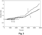
- Figure 3 shows the severity index (filtered) plotted for several driving profiles.
- the severe driving profiles 10 are clearly identified by higher values (>>1.5) than nominal driving styles ( ⁇ 1.5) such as WLTC with or without slope, Artemis, or RDE.
- reference numerals 7 denotes RDE severe with slope
- 6 denotes RDE sever no slope.
- Less severe driving styles such as WLTC, RDE mild urban Artemis and RTS95 are shown designated with grouped reference numeral 8
- Figure 3 shows that e.g. EGR rate should increase with higher severity index.
- the severity index is used in calibration to apply appropriate control (compromise) when an aggressive driving style is detected.
- this may be allowing a temporary increase of PM (and CO2), allowing engine-out NOx to be reduced.
- EGR rate demands as a function of the severity index: this may be appied also on the base EGR rate demand and minimum EGR rate which is applied even when operating at the smoke limit. So in one example the EGR rate is increased depending on the severity index value.
- a nominal EGR rate is calibrated, considering a "normal" driving. This EGR rate gives the best compromise in terms of NOx / PM / CO2.
- Another EGR rate is calibrated, for a severe driving in order to reduce the engine-out NOx. This high EGR may affect the drivability or fuel consumption but is required to contain NOx emissions.
- the actual EGR rate applied may be e.g. interpolated between those two extreme cases depending on the calculated severity index described above.
- FIG. 4 shows a flowchart which gives an overview of one example and how severity index calculation is used for EGR rate adaption. The flowchart is simplified compared to the control strategy, the EGR rate modification is not detailed.
- step S1 the accumulated levels of CO2 and NOx are determined. These may be provided from models and this step may be performed over any appropriate time or mileage window. Where the methodology is performed over set mileage windows in step S3 it is determined whether the appropriate miles has elapsed. If so in step S4 the normal NOx output level for the CO2 accumulated level determined in step S2 is calculated. The accumulated NOx determined in step S2 is then divided by the normal NOx output level in step S5 to determine a raw severity index. In optional step S6 the result of step S5 is filtered to determine a (working) severity index. In step S7 it is determined if the severity index from step S7 is above a threshold and at step S8 if so the EGR rate is modified as a function of the severity index.
- This calculated NOx severity index can also be used to act on any other parameter which can affect NOx emissions.
- the EGR rate modification has been implemented but the severity index variable can also be used to increase AdBlue injection on an SCR system or adapt Lean NOx Trap regenerations frequency.
- the core of this invention is the calculation of a "NOx severity index" and its usage to influence the NOx production of the engine. It would have been possible to implement a simple NOx accumulator to estimate online NOx emissions (in mg/km), however this calculation would be much more dependent on the driving cycle and driving conditions (road slope for example) and not only on the driving style.
Landscapes
- Engineering & Computer Science (AREA)
- Chemical & Material Sciences (AREA)
- Combustion & Propulsion (AREA)
- Mechanical Engineering (AREA)
- General Engineering & Computer Science (AREA)
- Chemical Kinetics & Catalysis (AREA)
- Health & Medical Sciences (AREA)
- Toxicology (AREA)
- Combined Controls Of Internal Combustion Engines (AREA)
- Exhaust Gas After Treatment (AREA)
Description
- This application relates to a method of controlling vehicle emissions and has application to both petrol and Diesel engines. It has particular but not exclusive application to engines with Exhaust Gas Recirculation (EGR).
- With the introduction of Real Driving Emissions (RDE) for Euro 6d legislation, passenger cars have to fulfil certain emission limits under much wider conditions than in the past. With Euro 6b and earlier legislations, engine manufacturers were requested to comply with emission limits on the mild pseudo-steady-state NEDC cycle. Engine calibration has been mainly focused on this.
- In random driving conditions (non cycle), Euro 6d vehicles are therefore much cleaner than earlier legislation versions, especially in regards to NOx emissions of diesel vehicles.
- Controlling NOx emissions on RDE requires extensive use of all the available means provided by the engine H/W and after treatment system. However, lowering tailpipe NOx emissions has some associated drawbacks. Firstly on the engine-out side, increased Exhaust Gas Recirculation (EGR) (or, at a lower extent, injection retard) greatly reduce NOx but at the cost of increased particulates and CO2. Secondly on the after-treatment side, some gain in SCR NOx conversion performance can be achieved by thermal management to the cost of CO2 or by urea over dosing to the cost of increased urea consumption and/or increased NH3 emissions. An Lean NOx Trap (LNT) can also be regenerated at a higher frequency to improve NOx conversion, to the cost of increased CO2 and particulate matter (PM) emissions.
- Regarding emissions control, engine and after-treatment calibration is then focused on finding the best compromise in terms of NOx, PM, CO2 and urea consumption, that will meet emission legislation on all valid random driving styles, covering all extremes from mild driving styles generating low NOx to aggressive driving styles generating high NOx.
- Different approaches are taken to meet NOx emission limits under this wide range of extreme driving conditions.
- In the worst case approach, the emission limits are met under all theoretical driving styles, by increased EGR, and using an oversized after-treatment system for NOx conversion and PM management, SCR thermal management, over-regenerated LNT. This however provides significant CO2 penalty (and H/W cost).
- In a more pragmatic approach, the emission limits are met under all reasonable/average driving styles by the means listed above but not pushed to their limit. While this approach greatly limits the CO2 penalty, it also takes some legal risks, since it does not cover all theoretical driving styles.
- Known methods of controlling an engine based on estimating pollutant emissions such as NOx are known from
GB 2 531 368US 2017/248091 . - It is an object of the invention to overcome the aforementioned drawbacks of the prior art systems and to provide an improved and more flexible methodology to reduce the emissions without undue cost, and which meets legal requirements.
- In one aspect is provided a method of controlling a vehicle engine as claimed in
claim 1. Namely, a method of controlling a vehicle engine comprising a) determining at least two engine operational parameters selected from the following parameters: i) CO2 output, ii) power output iii) NOx output; b) averaging the values of said two parameters during a driving window; c) selecting reference driving conditions, collecting a number of points relating the selected engine operational parameters to populate a map of points during reference driving conditions, establishing a nominal reference curve relating said two of the following engine parameters, the reference curve being a best fit of the populated map of points which links the selected engine operational parameters; d) comparing the result from step b) with said reference curve from step c) to determine a measure of how far the parameter averages obtained from step b) are from the reference curve from step c) ; e) adjusting control of one or more engine systems dependent on the result of step d). - Said nominal reference curve may represent an averaged relationship between said two parameters under a plurality of driving conditions.
- Said driving window comprises a pre-determined driving distance or a predetermined time window.
- Said parameters in step a) may be NOx and CO2 outputs.
- One or more of said outputs are provided from a model.
- Step d) may comprise determining if said measure is more than a threshold..
- Step d) may comprises determining a driving index comprising :
- i) dividing the accumulated NOx during the driving window by the normal/nominal NOx that would be expected for the same accumulated CO2 output according to the reference curve, or
- ii) dividing the accumulated measured CO2 during the driving window by the normal/nominal CO2 that would be expected for the same accumulated NOx output according to the reference curve.
- Step e) may comprise adjusting the control of one or more engine systems comprises, dependent on step d) adjusting one or more of the following:
i) Urea /Ad Blue dosage in an SCR systems, ii) lean NOx trap regeneration frequency, iii) EGR rate, iv) injection timing and v) boost pressure. - The present invention is now described by way of example with reference to the accompanying drawings in which:
-
Figure 1 shows a number of points relating NOx output against CO2 output at varying output and for a number of driving styles; -
Figure 2 shows a standard reference curve offigure 2 in more detail; -
Figure 3 shows the severity index (filtered) plotted for several driving profiles -
Figure 4 shows a flowchart which gives an overview of one example - In one aspect the severity of driving style is analysed in the engine control software and may be ranked by providing an index with regards to engine-out NOx production, and this analysis is used to then automatically adapt online the engine-out calibration and controls such that the [NOx]/ [CO2, PM, urea consumption] compromise can be shifted towards lower NOx values when required (to prevent exceeding NOx emissions limits in case of aggressive driving style).
- In summary, one aspect of the invention comprise determining driving parameters relating the NOx output with respect to the power or CO2 output, (or relating the CO2 output with respect to the power or NOx output) and determining effectively how far this combined parameter is from a calibration curve or map, so as to e.g. provide a severity index. The severity index or how far the combined parameter is from the reference curve, is then used to control one or more the engine parameters (such as EGR/AdBlue/etc.) to optimize emissions reduction. The NOx and CO2 as power output may be measured or provided by models.
- Determining the parameters may be performed in a time or mileage window.
- With a well-balanced engine-out calibration, the energy specific NOx emissions (g of NOx per kWh or g of NOx per g of CO2) measured and averaged over a small distance follow a certain trend as long as no aggressive manoeuvers are applied from the driver.
- When considering an average driving style such as WLTC (Worldwide harmonized Light vehicles Test Cycle), the NOx produced by the engine follows a trend versus the CO2 (or energy) produced by the engine. By design, the WLTC is THE average driving style meant to correspond to the average human driving style (WLTC was developed in this sense).
- Some aggressive driving styles are challenging in terms of NOx production. A typical example is full load operation. At full load, the EGR rate is limited and the calibration is tuned to meet torque requirements while not producing excessive PM, which would accelerate DPF filling in the case of Diesel engines, require very frequent DPF regeneration and then increase CO2. If the driver then constantly toggles between full load and foot-off operation, the NOx production is abnormally high.
- A severity index implemented in examples is, for a given average CO2 produced or energy consumed, a measure of the ratio of averaged actual engine-out NOx emission divided by the averaged actual engine-out NOx under average/nominal driving conditions. Any average driving style data can be used to characterize the nominal EO (Engine-out emissions) NOx = f (average CO2) map which is then later used by the strategy to calculate the severity index.
- The average CO2 is calculated by converting injected fuel quantity to CO2 equivalent, while the average engine-out NOx is calculated by cumulating an embedded engine-out NOx model.
-
Figure 1 shows a number of points relating NOx output against CO2 output at varying output and for a number of driving styles. The driving styles are with reference numerals: WLTC withoutslope 1, 170832 urban noslope 2, T111 180312 with a 5%slope 3 and 170201 Artemis no slope, 4. Such driving conditions can thus provide points to populate a nominal EO NOx = f (average CO2) map, since all these driving styles are "average". The "calibration map" is then used to provide areference curve 5 to best fit the populated map which is then used as a reference map in embodiments of the invention; e.g. to determine and compare against a current driving style so as to e.g. determine a severity index; this the figure shows a typical calibration for the nominal NOx/CO2 map. - A raw severity index is calculated by firstly looking at the averaged CO2 and NOx over a calibratable mileage window (typically from few hundred meters to few km). Alternatively this may be done over a time window. This provides for example a point P on the chart of
figure 1 , shown again infigure 2 for clarity. - It is then decided e.g. to determine a severity index, to determine generally by how far away the point is from the form the calibration/
standard curve 5. This may be done by finding the shortest distance between point P and the curve, being dx. The skilled person would be aware of various ways in determining the severity index. - Alternatively and in refined embodiments, for example,
standard curve 5 may be used to determine a value of normal accumulated NOx (NNOx) for the averaged CO2 determined (e.g. by the model) during the mileage window. This is then compared to the averaged actual NOx (ANOx) during the mileage window to determine a severity index. Dependent on the severity index the engine may appropriately control the aforementioned systems (EGR /AdBlue urea NH3 control) to optimize the reduction in emission. - In one aspect the severity index is determined by dividing the accumulated measured NOx (for that time/mileage window= ANOx) by the normal/nominal NOx (NNOx) that would be expected for the same accumulated CO2 output according to
calibration curve 5. - Alternatively
standard curve 5 may be used to determine a value of normal accumulated CO2 (NCO2) for the averaged NOx determined (e.g. by the model) during the mileage window. This is then compared to the averaged actual CO2 (ACO2) during the mileage window to determine a severity index. - In one aspect the severity index is determined by dividing the accumulated measured NOx (for that time/mileage window) by the normal/nominal NOx that would be expected for the same accumulated CO2 output according to
calibration curve 5. - It should be noted that the severity index may be inherently determined simply by comparing the averaged actual NOx with the normally accumulated NOx for that CO2s output, or by determining comparing the averaged actual CO2 with the normally accumulated CO2 for that NOx output. So in one aspect such a comparison is made and if the difference between values is greater than a threshold, the engine controls the aforementioned systems appropriately. Thus the severity index may be simply be a "yes" or "no" on whether the appropriate parameters vary by more than a threshold.
- This raw index can still vary significantly during random driving conditions and the global driving style severity cannot be judged over only few kilometers. That is why the raw severity is preferably further filtered by a first order filter calculated every time the severity is calculated (for example every km).
-
Figure 3 shows the severity index (filtered) plotted for several driving profiles. The severe driving profiles 10 are clearly identified by higher values (>>1.5) than nominal driving styles (<1.5) such as WLTC with or without slope, Artemis, or RDE. The severe driving profiles driven in this example include many foot-on / foot-off operation from the driver, which explains abnormal (=much higher than mild/average driving) NOx production. In thefigure reference numerals 7 denotes RDE severe with slope, and 6 denotes RDE sever no slope. Less severe driving styles such as WLTC, RDE mild urban Artemis and RTS95 are shown designated with grouped reference numeral 8 -
Figure 3 shows that e.g. EGR rate should increase with higher severity index. Thus generally the severity index is used in calibration to apply appropriate control (compromise) when an aggressive driving style is detected. - In one example this may be allowing a temporary increase of PM (and CO2), allowing engine-out NOx to be reduced.
- In one aspect there is an automatic online modification of EGR rate demands as a function of the severity index: this may be appied also on the base EGR rate demand and minimum EGR rate which is applied even when operating at the smoke limit. So in one example the EGR rate is increased depending on the severity index value. A nominal EGR rate is calibrated, considering a "normal" driving. This EGR rate gives the best compromise in terms of NOx / PM / CO2. Another EGR rate is calibrated, for a severe driving in order to reduce the engine-out NOx. This high EGR may affect the drivability or fuel consumption but is required to contain NOx emissions. The actual EGR rate applied may be e.g. interpolated between those two extreme cases depending on the calculated severity index described above.
-
Figure 4 shows a flowchart which gives an overview of one example and how severity index calculation is used for EGR rate adaption. The flowchart is simplified compared to the control strategy, the EGR rate modification is not detailed. - The process starts at step S1. At
step 2 the accumulated levels of CO2 and NOx are determined. These may be provided from models and this step may be performed over any appropriate time or mileage window. Where the methodology is performed over set mileage windows in step S3 it is determined whether the appropriate miles has elapsed. If so in step S4 the normal NOx output level for the CO2 accumulated level determined in step S2 is calculated. The accumulated NOx determined in step S2 is then divided by the normal NOx output level in step S5 to determine a raw severity index. In optional step S6 the result of step S5 is filtered to determine a (working) severity index. In step S7 it is determined if the severity index from step S7 is above a threshold and at step S8 if so the EGR rate is modified as a function of the severity index. - This calculated NOx severity index can also be used to act on any other parameter which can affect NOx emissions. The EGR rate modification has been implemented but the severity index variable can also be used to increase AdBlue injection on an SCR system or adapt Lean NOx Trap regenerations frequency.
- The core of this invention is the calculation of a "NOx severity index" and its usage to influence the NOx production of the engine. It would have been possible to implement a simple NOx accumulator to estimate online NOx emissions (in mg/km), however this calculation would be much more dependent on the driving cycle and driving conditions (road slope for example) and not only on the driving style.
Claims (8)
- A method of controlling a vehicle engine comprisinga) determining at least two engine operational parameters selected from the following parameters: i) CO2 output, ii) power output iii) NOx output;b) averaging the values of said two parameters during a driving window;c) selecting reference driving conditions, collecting a number of points relating the selected engine operational parameters to populate a map of points during reference driving conditions, establishing a nominal reference curve relating said two of the following engine parameters, the reference curve being a best fit of the populated map of points which links the selected engine operational parameters;d) comparing the result from step b) with said reference curve from step c) to determine a
measure of how far the parameter averages obtained from step b) are from the reference curve from step c);e) adjusting control of one or more engine systems dependent on the result of step d). - A method as claimed in claim 1 wherein said nominal reference curve represents an averaged relationship between said two parameters under a plurality of driving conditions.
- A method as claimed in claim 1 to 2 wherein said driving window comprises a pre-determined driving distance or a predetermined time window.
- A method as claimed in claims 1 to 3 wherein said parameters in step a) are NOx and CO2 outputs.
- A method as claimed in claims 1 to 4 wherein one or more of said outputs are provided from a model.
- A method as claimed in claims 1 to 5 wherein step d) comprises determining if said measure is more than a threshold.
- A method as claimed in claims 1 to 6 wherein step d) comprises determining a driving index comprising:i) dividing the accumulated NOx during the driving window by the normal/nominal NOx that would be expected for the same accumulated CO2 output according to the reference curve, orii) dividing the accumulated measured CO2 during the driving window by the normal/nominal CO2 that would be expected for the same accumulated NOx output according to the reference curve.
- A method as claimed in claims 1 to 7 wherein in step e) comprises adjusting control of one or more engine systems comprises, dependent on step d) adjusting one or more of the following:
i) Urea /Ad Blue dosage in an SCR systems, ii) lean NOx trap regeneration frequency, iii) EGR rate, iv) injection timing and v) boost pressure.
Applications Claiming Priority (2)
| Application Number | Priority Date | Filing Date | Title |
|---|---|---|---|
| GB1817030.8A GB2578155B (en) | 2018-10-19 | 2018-10-19 | Method of controlling vehicle emissions |
| PCT/EP2019/077899 WO2020078959A1 (en) | 2018-10-19 | 2019-10-15 | Method of controlling vehicle emissions |
Publications (2)
| Publication Number | Publication Date |
|---|---|
| EP3867514A1 EP3867514A1 (en) | 2021-08-25 |
| EP3867514B1 true EP3867514B1 (en) | 2024-12-11 |
Family
ID=64453716
Family Applications (1)
| Application Number | Title | Priority Date | Filing Date |
|---|---|---|---|
| EP19787252.6A Active EP3867514B1 (en) | 2018-10-19 | 2019-10-15 | Method of controlling vehicle emissions |
Country Status (4)
| Country | Link |
|---|---|
| EP (1) | EP3867514B1 (en) |
| CN (1) | CN112888848B (en) |
| GB (1) | GB2578155B (en) |
| WO (1) | WO2020078959A1 (en) |
Families Citing this family (3)
| Publication number | Priority date | Publication date | Assignee | Title |
|---|---|---|---|---|
| CN114810396B (en) * | 2021-06-04 | 2023-05-26 | 长城汽车股份有限公司 | Engine control device, method for adjusting nitrogen oxide conversion rate and automobile |
| CN114810382B (en) * | 2022-03-31 | 2023-07-18 | 潍柴动力股份有限公司 | Exhaust emission control method, system and engine |
| CN115628143B (en) * | 2022-09-07 | 2024-05-03 | 重庆金康赛力斯新能源汽车设计院有限公司 | Automobile emission control method, device, computer equipment and storage medium |
Family Cites Families (12)
| Publication number | Priority date | Publication date | Assignee | Title |
|---|---|---|---|---|
| JPS59120740A (en) * | 1982-12-27 | 1984-07-12 | Toyota Motor Corp | Suction throttling control method for diesel engine |
| JPS63183248A (en) * | 1987-01-26 | 1988-07-28 | Honda Motor Co Ltd | Fuel supply control method during low load operation of internal combustion engine |
| JPH0737789B2 (en) * | 1988-10-17 | 1995-04-26 | 株式会社日立製作所 | Electronic control unit for multi-cylinder engine |
| DE19910336A1 (en) * | 1999-03-09 | 2000-09-21 | Porsche Ag | Process for checking the function of catalysts in internal combustion engines |
| JP4549738B2 (en) * | 2004-05-27 | 2010-09-22 | 株式会社日立製作所 | Vehicle control system, control system, and control method |
| JP2011247214A (en) * | 2010-05-28 | 2011-12-08 | Isuzu Motors Ltd | Fuel injection control device of internal combustion engine |
| DE102015222684B4 (en) * | 2014-11-17 | 2019-11-07 | Volkswagen Aktiengesellschaft | Control unit for an internal combustion engine |
| GB2531368B (en) * | 2015-02-11 | 2017-02-01 | Ford Global Tech Llc | A method for emissions regulation |
| GB2548831A (en) * | 2016-03-29 | 2017-10-04 | Delphi Int Operations Luxembourg Sarl | Method of detecting use of tuning kit |
| US20160252036A1 (en) * | 2016-05-10 | 2016-09-01 | Caterpillar Inc. | System and method for controlling air-fuel ratio |
| CN106593672B (en) * | 2016-12-30 | 2019-08-16 | 广西玉柴机器股份有限公司 | Diesel engine scaling method based on LCCE optimization |
| FR3062100B1 (en) * | 2017-01-24 | 2021-11-19 | Peugeot Citroen Automobiles Sa | CONTROL PROCESS OF A POWERTRAIN UNIT FOR DEPOLLUTION OF ITS EXHAUST LINE |
-
2018
- 2018-10-19 GB GB1817030.8A patent/GB2578155B/en active Active
-
2019
- 2019-10-15 CN CN201980068365.9A patent/CN112888848B/en active Active
- 2019-10-15 EP EP19787252.6A patent/EP3867514B1/en active Active
- 2019-10-15 WO PCT/EP2019/077899 patent/WO2020078959A1/en not_active Ceased
Also Published As
| Publication number | Publication date |
|---|---|
| CN112888848B (en) | 2023-06-06 |
| WO2020078959A1 (en) | 2020-04-23 |
| EP3867514A1 (en) | 2021-08-25 |
| CN112888848A (en) | 2021-06-01 |
| GB201817030D0 (en) | 2018-12-05 |
| GB2578155B (en) | 2021-01-13 |
| GB2578155A (en) | 2020-04-22 |
Similar Documents
| Publication | Publication Date | Title |
|---|---|---|
| US8051645B2 (en) | Determination of diesel particulate filter load under both transient and steady state drive cycles | |
| US7065960B2 (en) | Method for activation of the regeneration of a particulate filter based on an estimate of the quantity of particulate accumulated in the particulate filter | |
| US9038370B2 (en) | Method for operating an exhaust emission control system having a SCR-catalyst and an upstream oxidation catalyst exhaust emission control component | |
| EP3867514B1 (en) | Method of controlling vehicle emissions | |
| EP1544432B1 (en) | Regeneration control of diesel particulate filter | |
| RU2550219C2 (en) | Method and system for regeneration of diesel particulate filter | |
| RU2535440C2 (en) | Method and system of exhaust gases cleaning | |
| US7886521B2 (en) | Diagnosis device of exhaust purification catalyst | |
| US20200063632A1 (en) | Systems and methods for particulate filter regeneration | |
| EP1959108A1 (en) | Method for controlling exhaust gas purification system | |
| US20130085733A1 (en) | NOx EMISSION ESTIMATION METHOD AND ARRANGEMENT | |
| GB2479196A (en) | Method for regenerating a particulate filter using a navigation system | |
| US7765791B2 (en) | System for evaluating degree of soot loading in depollution means | |
| CN115405397B (en) | Controlling urea injection in an exhaust aftertreatment system | |
| CN102787924A (en) | Method for biodiesel blending detection based on fuel post-injection quantity evaluation | |
| US10577998B2 (en) | Method for controlling a regeneration of a particle filter of an internal combustion engine | |
| CN111022202B (en) | A method and device for controlling front exhaust temperature of construction machinery DPF | |
| GB2456060A (en) | Filter regeneration | |
| CN112776791B (en) | Method and device for reducing emissions of a hybrid motor vehicle | |
| US10815850B2 (en) | Method for catalyst purge control based on engine temperature and vehicle using the same | |
| Krüger et al. | Further optimization of NOx emissions under the EU 6d regulation | |
| US7493755B2 (en) | System for assisting the regeneration of depollution means for a motor vehicle engine | |
| US11333094B2 (en) | Method for estimating the ageing of an exhaust gas sensor and an industrial vehicle for implementing this method | |
| KR20200069734A (en) | Method for regeneration of gasoline particulate filter | |
| US7765796B2 (en) | System for assisting the regeneration of depollution means for a motor vehicle engine |
Legal Events
| Date | Code | Title | Description |
|---|---|---|---|
| STAA | Information on the status of an ep patent application or granted ep patent |
Free format text: STATUS: UNKNOWN |
|
| STAA | Information on the status of an ep patent application or granted ep patent |
Free format text: STATUS: THE INTERNATIONAL PUBLICATION HAS BEEN MADE |
|
| PUAI | Public reference made under article 153(3) epc to a published international application that has entered the european phase |
Free format text: ORIGINAL CODE: 0009012 |
|
| STAA | Information on the status of an ep patent application or granted ep patent |
Free format text: STATUS: REQUEST FOR EXAMINATION WAS MADE |
|
| 17P | Request for examination filed |
Effective date: 20210519 |
|
| AK | Designated contracting states |
Kind code of ref document: A1 Designated state(s): AL AT BE BG CH CY CZ DE DK EE ES FI FR GB GR HR HU IE IS IT LI LT LU LV MC MK MT NL NO PL PT RO RS SE SI SK SM TR |
|
| DAV | Request for validation of the european patent (deleted) | ||
| DAX | Request for extension of the european patent (deleted) | ||
| STAA | Information on the status of an ep patent application or granted ep patent |
Free format text: STATUS: EXAMINATION IS IN PROGRESS |
|
| P01 | Opt-out of the competence of the unified patent court (upc) registered |
Effective date: 20230327 |
|
| 17Q | First examination report despatched |
Effective date: 20230525 |
|
| GRAP | Despatch of communication of intention to grant a patent |
Free format text: ORIGINAL CODE: EPIDOSNIGR1 |
|
| STAA | Information on the status of an ep patent application or granted ep patent |
Free format text: STATUS: GRANT OF PATENT IS INTENDED |
|
| RAP3 | Party data changed (applicant data changed or rights of an application transferred) |
Owner name: BORGWARNER LUXEMBOURG AUTOMOTIVE SYSTEMS S.A. |
|
| INTG | Intention to grant announced |
Effective date: 20240522 |
|
| RAP1 | Party data changed (applicant data changed or rights of an application transferred) |
Owner name: PHINIA DELPHI LUXEMBOURG SARL |
|
| GRAJ | Information related to disapproval of communication of intention to grant by the applicant or resumption of examination proceedings by the epo deleted |
Free format text: ORIGINAL CODE: EPIDOSDIGR1 |
|
| STAA | Information on the status of an ep patent application or granted ep patent |
Free format text: STATUS: EXAMINATION IS IN PROGRESS |
|
| GRAP | Despatch of communication of intention to grant a patent |
Free format text: ORIGINAL CODE: EPIDOSNIGR1 |
|
| STAA | Information on the status of an ep patent application or granted ep patent |
Free format text: STATUS: GRANT OF PATENT IS INTENDED |
|
| INTC | Intention to grant announced (deleted) | ||
| GRAS | Grant fee paid |
Free format text: ORIGINAL CODE: EPIDOSNIGR3 |
|
| GRAA | (expected) grant |
Free format text: ORIGINAL CODE: 0009210 |
|
| STAA | Information on the status of an ep patent application or granted ep patent |
Free format text: STATUS: THE PATENT HAS BEEN GRANTED |
|
| INTG | Intention to grant announced |
Effective date: 20241010 |
|
| AK | Designated contracting states |
Kind code of ref document: B1 Designated state(s): AL AT BE BG CH CY CZ DE DK EE ES FI FR GB GR HR HU IE IS IT LI LT LU LV MC MK MT NL NO PL PT RO RS SE SI SK SM TR |
|
| REG | Reference to a national code |
Ref country code: GB Ref legal event code: FG4D |
|
| REG | Reference to a national code |
Ref country code: CH Ref legal event code: EP |
|
| REG | Reference to a national code |
Ref country code: IE Ref legal event code: FG4D |
|
| REG | Reference to a national code |
Ref country code: DE Ref legal event code: R096 Ref document number: 602019063419 Country of ref document: DE |
|
| REG | Reference to a national code |
Ref country code: LT Ref legal event code: MG9D |
|
| PG25 | Lapsed in a contracting state [announced via postgrant information from national office to epo] |
Ref country code: HR Free format text: LAPSE BECAUSE OF FAILURE TO SUBMIT A TRANSLATION OF THE DESCRIPTION OR TO PAY THE FEE WITHIN THE PRESCRIBED TIME-LIMIT Effective date: 20241211 |
|
| PG25 | Lapsed in a contracting state [announced via postgrant information from national office to epo] |
Ref country code: FI Free format text: LAPSE BECAUSE OF FAILURE TO SUBMIT A TRANSLATION OF THE DESCRIPTION OR TO PAY THE FEE WITHIN THE PRESCRIBED TIME-LIMIT Effective date: 20241211 |
|
| PG25 | Lapsed in a contracting state [announced via postgrant information from national office to epo] |
Ref country code: BG Free format text: LAPSE BECAUSE OF FAILURE TO SUBMIT A TRANSLATION OF THE DESCRIPTION OR TO PAY THE FEE WITHIN THE PRESCRIBED TIME-LIMIT Effective date: 20241211 |
|
| REG | Reference to a national code |
Ref country code: NL Ref legal event code: MP Effective date: 20241211 |
|
| PG25 | Lapsed in a contracting state [announced via postgrant information from national office to epo] |
Ref country code: ES Free format text: LAPSE BECAUSE OF FAILURE TO SUBMIT A TRANSLATION OF THE DESCRIPTION OR TO PAY THE FEE WITHIN THE PRESCRIBED TIME-LIMIT Effective date: 20241211 |
|
| PG25 | Lapsed in a contracting state [announced via postgrant information from national office to epo] |
Ref country code: NO Free format text: LAPSE BECAUSE OF FAILURE TO SUBMIT A TRANSLATION OF THE DESCRIPTION OR TO PAY THE FEE WITHIN THE PRESCRIBED TIME-LIMIT Effective date: 20250311 |
|
| PG25 | Lapsed in a contracting state [announced via postgrant information from national office to epo] |
Ref country code: GR Free format text: LAPSE BECAUSE OF FAILURE TO SUBMIT A TRANSLATION OF THE DESCRIPTION OR TO PAY THE FEE WITHIN THE PRESCRIBED TIME-LIMIT Effective date: 20250312 Ref country code: LV Free format text: LAPSE BECAUSE OF FAILURE TO SUBMIT A TRANSLATION OF THE DESCRIPTION OR TO PAY THE FEE WITHIN THE PRESCRIBED TIME-LIMIT Effective date: 20241211 |
|
| PG25 | Lapsed in a contracting state [announced via postgrant information from national office to epo] |
Ref country code: RS Free format text: LAPSE BECAUSE OF FAILURE TO SUBMIT A TRANSLATION OF THE DESCRIPTION OR TO PAY THE FEE WITHIN THE PRESCRIBED TIME-LIMIT Effective date: 20250311 |
|
| PG25 | Lapsed in a contracting state [announced via postgrant information from national office to epo] |
Ref country code: NL Free format text: LAPSE BECAUSE OF FAILURE TO SUBMIT A TRANSLATION OF THE DESCRIPTION OR TO PAY THE FEE WITHIN THE PRESCRIBED TIME-LIMIT Effective date: 20241211 |
|
| REG | Reference to a national code |
Ref country code: AT Ref legal event code: MK05 Ref document number: 1750537 Country of ref document: AT Kind code of ref document: T Effective date: 20241211 |
|
| PG25 | Lapsed in a contracting state [announced via postgrant information from national office to epo] |
Ref country code: SM Free format text: LAPSE BECAUSE OF FAILURE TO SUBMIT A TRANSLATION OF THE DESCRIPTION OR TO PAY THE FEE WITHIN THE PRESCRIBED TIME-LIMIT Effective date: 20241211 |
|
| PG25 | Lapsed in a contracting state [announced via postgrant information from national office to epo] |
Ref country code: PL Free format text: LAPSE BECAUSE OF FAILURE TO SUBMIT A TRANSLATION OF THE DESCRIPTION OR TO PAY THE FEE WITHIN THE PRESCRIBED TIME-LIMIT Effective date: 20241211 |
|
| PG25 | Lapsed in a contracting state [announced via postgrant information from national office to epo] |
Ref country code: IS Free format text: LAPSE BECAUSE OF FAILURE TO SUBMIT A TRANSLATION OF THE DESCRIPTION OR TO PAY THE FEE WITHIN THE PRESCRIBED TIME-LIMIT Effective date: 20250411 |
|
| PG25 | Lapsed in a contracting state [announced via postgrant information from national office to epo] |
Ref country code: PT Free format text: LAPSE BECAUSE OF FAILURE TO SUBMIT A TRANSLATION OF THE DESCRIPTION OR TO PAY THE FEE WITHIN THE PRESCRIBED TIME-LIMIT Effective date: 20250411 |
|
| PG25 | Lapsed in a contracting state [announced via postgrant information from national office to epo] |
Ref country code: EE Free format text: LAPSE BECAUSE OF FAILURE TO SUBMIT A TRANSLATION OF THE DESCRIPTION OR TO PAY THE FEE WITHIN THE PRESCRIBED TIME-LIMIT Effective date: 20241211 |
|
| PG25 | Lapsed in a contracting state [announced via postgrant information from national office to epo] |
Ref country code: RO Free format text: LAPSE BECAUSE OF FAILURE TO SUBMIT A TRANSLATION OF THE DESCRIPTION OR TO PAY THE FEE WITHIN THE PRESCRIBED TIME-LIMIT Effective date: 20241211 Ref country code: AT Free format text: LAPSE BECAUSE OF FAILURE TO SUBMIT A TRANSLATION OF THE DESCRIPTION OR TO PAY THE FEE WITHIN THE PRESCRIBED TIME-LIMIT Effective date: 20241211 |
|
| PG25 | Lapsed in a contracting state [announced via postgrant information from national office to epo] |
Ref country code: SK Free format text: LAPSE BECAUSE OF FAILURE TO SUBMIT A TRANSLATION OF THE DESCRIPTION OR TO PAY THE FEE WITHIN THE PRESCRIBED TIME-LIMIT Effective date: 20241211 |
|
| PG25 | Lapsed in a contracting state [announced via postgrant information from national office to epo] |
Ref country code: CZ Free format text: LAPSE BECAUSE OF FAILURE TO SUBMIT A TRANSLATION OF THE DESCRIPTION OR TO PAY THE FEE WITHIN THE PRESCRIBED TIME-LIMIT Effective date: 20241211 |
|
| PG25 | Lapsed in a contracting state [announced via postgrant information from national office to epo] |
Ref country code: IT Free format text: LAPSE BECAUSE OF FAILURE TO SUBMIT A TRANSLATION OF THE DESCRIPTION OR TO PAY THE FEE WITHIN THE PRESCRIBED TIME-LIMIT Effective date: 20241211 |
|
| PG25 | Lapsed in a contracting state [announced via postgrant information from national office to epo] |
Ref country code: SE Free format text: LAPSE BECAUSE OF FAILURE TO SUBMIT A TRANSLATION OF THE DESCRIPTION OR TO PAY THE FEE WITHIN THE PRESCRIBED TIME-LIMIT Effective date: 20241211 |
|
| REG | Reference to a national code |
Ref country code: DE Ref legal event code: R097 Ref document number: 602019063419 Country of ref document: DE |
|
| PG25 | Lapsed in a contracting state [announced via postgrant information from national office to epo] |
Ref country code: DK Free format text: LAPSE BECAUSE OF FAILURE TO SUBMIT A TRANSLATION OF THE DESCRIPTION OR TO PAY THE FEE WITHIN THE PRESCRIBED TIME-LIMIT Effective date: 20241211 |
|
| PGFP | Annual fee paid to national office [announced via postgrant information from national office to epo] |
Ref country code: GB Payment date: 20250911 Year of fee payment: 7 |
|
| PLBE | No opposition filed within time limit |
Free format text: ORIGINAL CODE: 0009261 |
|
| STAA | Information on the status of an ep patent application or granted ep patent |
Free format text: STATUS: NO OPPOSITION FILED WITHIN TIME LIMIT |
|
| PGFP | Annual fee paid to national office [announced via postgrant information from national office to epo] |
Ref country code: FR Payment date: 20250912 Year of fee payment: 7 |
|
| 26N | No opposition filed |
Effective date: 20250912 |
|
| PGFP | Annual fee paid to national office [announced via postgrant information from national office to epo] |
Ref country code: DE Payment date: 20250912 Year of fee payment: 7 |