EP3867141B1 - Life preserver - Google Patents
Life preserver Download PDFInfo
- Publication number
- EP3867141B1 EP3867141B1 EP19787258.3A EP19787258A EP3867141B1 EP 3867141 B1 EP3867141 B1 EP 3867141B1 EP 19787258 A EP19787258 A EP 19787258A EP 3867141 B1 EP3867141 B1 EP 3867141B1
- Authority
- EP
- European Patent Office
- Prior art keywords
- buoyancy
- wearer
- life preserver
- chin support
- region
- Prior art date
- Legal status (The legal status is an assumption and is not a legal conclusion. Google has not performed a legal analysis and makes no representation as to the accuracy of the status listed.)
- Active
Links
Images


Classifications
-
- B—PERFORMING OPERATIONS; TRANSPORTING
- B63—SHIPS OR OTHER WATERBORNE VESSELS; RELATED EQUIPMENT
- B63C—LAUNCHING, HAULING-OUT, OR DRY-DOCKING OF VESSELS; LIFE-SAVING IN WATER; EQUIPMENT FOR DWELLING OR WORKING UNDER WATER; MEANS FOR SALVAGING OR SEARCHING FOR UNDERWATER OBJECTS
- B63C9/00—Life-saving in water
- B63C9/08—Life-buoys, e.g. rings; Life-belts, jackets, suits, or the like
- B63C9/11—Life-buoys, e.g. rings; Life-belts, jackets, suits, or the like covering the torso, e.g. harnesses
- B63C9/125—Life-buoys, e.g. rings; Life-belts, jackets, suits, or the like covering the torso, e.g. harnesses having gas-filled compartments
- B63C9/1255—Life-buoys, e.g. rings; Life-belts, jackets, suits, or the like covering the torso, e.g. harnesses having gas-filled compartments inflatable
-
- B—PERFORMING OPERATIONS; TRANSPORTING
- B63—SHIPS OR OTHER WATERBORNE VESSELS; RELATED EQUIPMENT
- B63C—LAUNCHING, HAULING-OUT, OR DRY-DOCKING OF VESSELS; LIFE-SAVING IN WATER; EQUIPMENT FOR DWELLING OR WORKING UNDER WATER; MEANS FOR SALVAGING OR SEARCHING FOR UNDERWATER OBJECTS
- B63C9/00—Life-saving in water
- B63C9/08—Life-buoys, e.g. rings; Life-belts, jackets, suits, or the like
-
- B—PERFORMING OPERATIONS; TRANSPORTING
- B63—SHIPS OR OTHER WATERBORNE VESSELS; RELATED EQUIPMENT
- B63C—LAUNCHING, HAULING-OUT, OR DRY-DOCKING OF VESSELS; LIFE-SAVING IN WATER; EQUIPMENT FOR DWELLING OR WORKING UNDER WATER; MEANS FOR SALVAGING OR SEARCHING FOR UNDERWATER OBJECTS
- B63C9/00—Life-saving in water
- B63C9/08—Life-buoys, e.g. rings; Life-belts, jackets, suits, or the like
- B63C9/18—Inflatable equipment characterised by the gas-generating or inflation device
Definitions
- the present invention relates to a life preserver comprising first and second buoyancy sections arranged such that, in use, the first and second buoyancy sections lie on opposite sides respectively of a wearer's chest.
- life preservers such as lifejackets
- Life jackets typically include an opening for the wearer's head and neck.
- a problem with known lifejackets is that, in use, water tends to flow into a wearer's mouth which can cause drowning, especially if a wearer is unconscious. This is especially a problem with split-front twin lobe lifejackets.
- Such lifejackets generally have two symmetrical lobes which lie on opposite sides of a wearer's chest. A channel is defined between the lobes, up the middle of the wearer's chest. In use, water tends to flow up this channel, towards the wearer's mouth.
- a further problem is that, in use, the action of water on the buoyancy section causes the buoyancy section to ride up over a wearer's head. This is especially a problem with large lifejackets.
- GB2480255 discloses a lifejacket having first and second buoyancy sections arranged such that, in use, the first and second buoyancy sections lie on opposite sides respectively of a wearer's chest.
- first and second buoyancy sections When the first and second buoyancy sections are brought together in a side-by-side abutting relationship, a space is defined between the first and second buoyancy sections below a wearer's chin and the first buoyancy section is provided with a chin support which extends from the first buoyancy section into said space.
- the chin support may be integral with the first buoyancy section and may abut the chest of the wearer and the second buoyancy section.
- WO93/13978 discloses an inflatable life jacket which is held in a horse-shoe shaped cover from which the jacket breaks free when inflated.
- the jacket has two legs and a rear portion. The rear portion fits behind the user's head and the legs locate to opposite sides of the user's chest.
- the legs are approximately of equal length but their inner edges are profiled so that one has a major section which extends across the user's chest and a minor lobe which lies adjacent the user's neck and the other leg has a major lobe which also extends across the user's chest and registers with a narrow portion of the other leg lying between the major section and inner lobe so as to interfit with said narrow portion and to underlie (at least partially) said other leg to prevent the formation of a water channel between the legs.
- the rear portion has extension lobes to increase buoyancy behind the head.
- Embodiments of the present invention seek to provide an improved life preserver.
- a life preserver comprising first and second buoyancy sections arranged such that, in use, the first and second buoyancy sections lie on opposite sides respectively of a wearer's chest, wherein said first and second buoyancy sections include respective inner facing regions that face one another above respective opposite sides of the wearer's chest, each of the inner facing regions having a chin support portion and being configured to abut each other substantially at the centre of the wearer's chest in use to form a chin support.
- each of said first and second buoyancy sections includes an outer region at an opposite side thereof to the inner facing region, wherein each chin support portion extends from its corresponding outer region.
- each of the chin support portions is folded across buoyancy section from which it extends. In this way, the chin support portions come to be positioned at the inner facing regions of the first and second buoyancy sections, despite extending from the outer regions of first and second buoyancy sections.
- each of chin support portions is attached to the inner facing region of the buoyancy section from which it extends. In the embodiment, the attachment happens after the folding.
- the inner facing region includes a connection portion for attachment to the chin support portion. This may ease the attachment of the chin support portions to the inner facing region of the buoyancy section.
- each of the chin support portions includes a first part and a second part, the first part being folded over the second part to form respective folded chin support portions. This may form a fairly rigid protruding surface to support the chin above the water in use.
- the abutting chin support regions are configured to tend to maintain the inner facing regions of the first and second buoyancy sections spaced apart. This may allow water to pass between the first and second buoyancy sections. The flow of water may be broken by the chin support and so tends not to enter the wearer's mouth.
- the first and second buoyancy sections are inflatable. This provides buoyancy in a convenient manner and allows the life preserver to be stored in a compact, deflated form.
- the life preserver is conveniently formed in the embodiment by two sheets of material, forming the first and second buoyancy sections, the sheets of material being selectively joined at connection regions to define an inflatable volume.
- At least one of the first and second buoyancy sections includes a relatively reduced depth region between an upper portion and a lower portion thereof to facilitate relative rotation between the upper portion and a lower portion. This may allow the orientation of the lower portion of the buoyancy section to change so that the instead of lying generally parallel to the front of the wearer's chest, the lower portion of the buoyancy section extends generally perpendicularly to or obliquely to the front of the wearer's chest (e.g. at an angle of 45-90 degrees to the front of the wearer's chest).
- the reduced depth region may be a non-inflated region of the buoyancy section.
- the non-inflated region may be formed by one of the connection regions.
- the upper portion is configured to support the wearer's neck or head in use.
- first and second buoyancy sections are symmetrical.
- the chin support may act to close the wearer's mouth, to prevent the wearer from swallowing any water that is channelled towards his mouth. In addition, the chin support tilts the wearer's head away from the level of the water.
- a further advantage may be that a chin support is provided without requiring the first and second buoyancy sections to abut or overlap. Accordingly, even if the second buoyancy section is moved away from the first buoyancy section, for example due to the action of waves, the wearer's chin may still be supported by the chin support - by one or both chin support portions). Furthermore, it is not necessary for the first or second buoyancy sections to form a close fit with the wearer's neck, in order to provide support to the wearer's chin. Such a close fit can feel uncomfortable and restrictive. This is particularly important when considering that lifejackets must work in conjunction with large subject size ranges and when worn with immersion suits on multiple layers of clothing.
- the chin support when the chin support is nested under the wearer's chin, it acts to prevent the first buoyancy section from riding up over the wearer's head.
- a life preserver 1 such as a lifejacket.
- the life preserver 1 comprises a body 2 that is generally horse-shoe shaped and is for fitting around a wearer's neck.
- the body 2 comprises first and second inflatable buoyancy sections 3 and 4 which form symmetrically disposed legs of the horse-shoe, arranged to lie on opposite sides of a wearer's torso. First ends of the first and second buoyancy sections 3, 4 are joined together by a neck portion 5. The first and second buoyancy sections 3, 4 each extend from said first end to a second end, which is a free end. The first and second buoyancy sections 3, 4, together with the neck portion 5, define an aperture 6 for receiving a wearer's head and neck.
- the lifejacket body 2 is formed from first and second layers of material sealed together along a seam 7 (as described below), towards a peripheral edge, to define a body inflation chamber 8.
- the layers of material protrude from the seam 7 to form an edge 30.
- each buoyancy section 3, 4 is an elongate member of generally oval cross section.
- the inflation chamber 8 is connected to an inflation cartridge 9, containing compressed gas, that can be manually or automatically actuated. Following actuation, the inflation cartridge inflates the body inflation chamber 8.
- Each buoyancy section 3, 4 is provided with a mouth-operable inflator in the form of a tube 10 connected to the interior of the body inflation chamber 8. This allows manual inflation of the body inflation chamber 8 in the event of failure of the inflation cartridge 9.
- Each tube 10 is provided with a non-return valve and a closure cap to prevent water flowing down the tube and into the body inflation chamber 8.
- first and second buoyancy sections 3, 4 lie on opposite sides respectively of a wearer's chest, in side-by-side relationship.
- first and second buoyancy sections 3, 4 define a space below the wearer's chin.
- Each of the first and second buoyancy sections 3, 4 are provided with an integral chin support 11A, 11B which extend from a portion of the first and second buoyancy sections 3, 4 provided towards the neck aperture 6.
- the chin support 11A is integral with the first buoyancy section 3.
- the chin support 11B is integral with the second buoyancy section 4.
- the chin support When the chin support is nested under the wearer's chin, it acts to prevent the first and second buoyancy sections 3, 4 from riding up over the wearer's head.
- Figure 3 shows a plan view of a first layer of material used to form the life preserver 1.
- a second, substantially identical, layer is placed over the first layer and aligned with the first layer.
- the first and second layers of material are then heat sealed together along the seam 7.
- a layer of heat melt adhesive is provided between the first and second layers of material.
- the first and second layers of material may be attached by any other suitable method.
- the first and second layers of material are a plastic-coated fabric that is gas impermeable. It will be appreciated that any suitable material or method of heat sealing may be used.
- the chin supports 11A and 11B are formed by generally T-shaped wings 38A, 38B that extend from (and are integrally formed with) an outer region 39A of the first buoyancy section 3 and an outer region 39B of the second buoyancy section 4, respectively.
- connection portion 40A of the first buoyancy section 3 has a connection portion 40A extending therefrom (and are integrally formed therewith).
- An inner facing region 41B of the second buoyancy section 4 has a connection portion 4OB extending therefrom (and are integrally formed therewith).
- connection portions 40A and 40B are shown connected to one another. Such a connection may exist during manufacture, but is broken before use to separate the connection portions 40A and 40B from one another.
- the life preserver 1 is formed by sealing said first and second layers of material together along the seam 7.
- the seam extends around the first and second buoyancy sections 3, 4; the wings 38A, 38B; the connection portions 40A; and the neck portion 5.
- a single inflatable chamber 8 is formed within the volume defined by the seam 7.
- the seam 7 extends between the first buoyancy section 3 and the first connection region 40A to define defines a first non-inflated region 42A.
- the first non-inflated region 42A facilitates folding of the first connection region 40A with respect to the first buoyancy section 3.
- the seam 7 extends between the second buoyancy section 4 and the second connection region 40B to define defines a second non-inflated region 42B.
- the second non-inflated region 42B facilitates folding of the second connection region 4OB with respect to the second buoyancy section 4.
- the generally T-shaped wing 38A comprises a stem portion 44A that connects to the outer region 39A of the first buoyancy section 3. Inflation gas passes from the first buoyancy section 3 to the generally T-shaped wing 38A in the channel between the seams 7 in the stem portion 44A.
- the narrowness of the stem portion 44A facilitates folding of the stem portion 44A
- the stem portion 44A connects to an upper head portion 46A and a lower head portion 48A of the generally T-shaped wing 38A.
- the lower head portion 48A includes a reduced width region 49A, where one side tapers towards the other, and which facilitates folding of the lower head portion 4SA over the upper head portion 46A.
- the seam 7 extends from the outer side inwards and downwardly towards the opening 6. This defines a reduced depth, uninflated region 50A.
- the uninflated region 50A facilities rotation of the first buoyancy section 3 with respect to the neck portion 5.
- the life preserver 1 is symmetrical about the longitudinal axis (generally parallel to the wearer's spine).
- the generally T-shaped wing 38B comprises a stem portion 44B that connects to the outer region 39B of the second buoyancy section 4. Inflation gas passes from the second buoyancy section 4 to the generally T-shaped wing 38B in the channel between the seams 7 in the stem portion 44B.
- the narrowness of the stem portion 44B facilitates folding of the stem portion 44B.
- the stem portion 44B connects to an upper head portion 46B and a lower head portion 48B of the generally T-shaped wing 38B.
- the lower head portion includes a reduced width region 49B, where one side tapers towards the other, and which facilitates folding of the lower head portion 48B over the upper head portion 46B.
- the seam 7 extends from the outer side inwards and downwardly towards the opening 6. This defines a reduced depth, uninflated region SOB.
- the uninflated region SOB facilities rotation of the second buoyancy section 4 with respect to the neck portion S.
- the uninflated regions SOA, SOB may overlie the wearer's shoulders in use (the shoulders engaging the rear side of the life preserver 1).
- the wearer's head/neck passes through the opening 6 and engages the front side of the life preserver 1.
- Figures 4 and 5 show the formation of the chin support portions 11A, 11B.
- the lower head portion 48A of the wing portion 38A is folded at reduced width region 49A so that it overlies the upper head portion 46A.
- the free ends of the lower head portion 48A and the upper head portion 46A are then connected at line 62A, e.g. by welding.
- the lower head portion 48B of the wing portion 38B is folded at reduced width region 49B so that it overlies the upper head portion 46B.
- the free ends of the lower head portion 48B and the upper head portion 46B are then connected at line 62B, e.g. by welding.
- the head (comprising the upper head portion 46A and a lower head portion 48A) of the wing portion 38A is folded along fold line 64A of the stem 44A.
- the lower head portion 48A then overlies the first buoyancy section 3 and the connection portion 40A.
- the connected lower head portion 48A and upper head portion 46A at line 62A are then connected to a distal edge 66A of the connection portion 40A, e.g. by welding.
- the head (comprising the upper head portion 46B and a lower head portion 48B) of the wing portion 38B is folded along fold line 64B the stem 44B.
- the lower head portion 48B then overlies the second buoyancy section 4 and the connection portion 40B.
- the connected lower head portion 48B and upper head portion 46B at line 62B are then connected to a distal edge 66B of the connection portion 40B, e.g. by welding.
- the second step together with inflation, causes the first and second buoyancy section 3, 4 to rotate in opposite directions by approximately 45 degrees with respect to the neck portion 5, facilitated by the uninflated regions 50A, SOB.
- the upper faces (as shown in Figure 5 ) of the lower head portions 48A and 48B become generally parallel to one another and are configured to abut in use. This brings the upper faces (as shown in Figure 5 ) of the upper head portions 46A, 46B together to form a chin support will in use contact the wearer's chin.
- chin supports 11A, 11B have a low volume and depth they are readily deformable, providing for comfort around the neck and chin.
- the lower head portions 48A and 48B running generally perpendicular to the chest provide vertical support to especially prevent ride up of the life preserver 1 over the wearer's head.
- One or more straps may be attached to the life preserver 1 and may pass around the torso of the wearer to secure the lifejacket 1 to the wearer. Examples of suitable strap arrangements are described below in relation to Figures 8 , 9 and 10 .
- first and second buoyancy section 3, 4 are generally oval in transverse cross-section, the width dimension being greater than the depth dimension.
- the uninflated regions SOA, SOB allow the first and second buoyancy sections 3, 4 to rotate relative to the neck portion S so that the larger dimension, instead of overlying and being generally parallel to the chest of the wearer, extends generally perpendicular to or obliquely to the chest of the wearer.
- the uninflated regions SOA, SOB provide pivot hinges for the 3D shaping of the life preserver 1.
- the uninflated regions SOA, SOB overlie the wearer's shoulders in use.
- uninflated regions SOA, SOB and the larger depth neck section S can sit on the same plane i.e. the uninflated regions SOA, SOB allow a uniform bend to the life preserver 1 without the shoulder regions collapsing due to twisting (the first and second buoyancy sections 3, 4 are held at an angle of approximately 4S°-90° to the neck section S) and allow the neck section S to sit at the same height.
- the hinge point formed by the uninflated regions SOA, SOB allows for this twisting.
- the uninflated region SOA allows the right-hand side (viewed from the front) buoyancy section 3 to twist or rotate clockwise with respect to the neck section S (about an axis generally parallel with the wearer's spine).
- the uninflated region SOB allows the left-hand side (viewed from the front) buoyancy section 4 to twist or rotate anti-clockwise with respect to the neck section 5 (about an axis generally parallel with the wearer's spine).
- the uninflated regions 50A, SOB reduce the tendency for the adjacent inflated region to collapse due to the twisting or rotation.
- the chin support may cause the first and second buoyancy sections 3, 4 to be spaced apart.
- the chin support can break the flow of water flowing between the first and second buoyancy sections 3, 4.
- the chin support supports the wearer's chin at a relatively large height above the water level.
- the chin support acts to close the wearer's mouth, thereby preventing the wearer from swallowing any water that is channelled towards his mouth. In addition, the chin support tilts the wearer's mouth away from the water.
- the chin support when the chin support is nested under the wearer's chin, it acts to prevent the first and second buoyancy sections 3, 4 from riding up over the wearer's head.
- Figures 8 , 9 and 10 show example arrangements for straps to attach the life preserver 1 to the wearer 100.
- a front strap 102 may releasably connect together the first and second buoyancy sections 3, 4 near the distal ends thereof (near the wearer's waist, to the front thereof).
- a first portion of the front strap 102 is attached to the right lobe 3, a second portion of the front strap 102 is attached to the left lobe 4, and a buckle 104 releasably attaches the portions together.
- Two crotch straps 110 may releasably connect the first and second buoyancy sections 3, 4 at the distal ends thereof (near the wearer's waist) to the neck portion 5 via a back strap 112 which extends along the wearer's back.
- the crotch straps 110 meet between the wearer's legs and connect to the back strap 112.
- a first one of the crotch straps 110 is attached to the right lobe 3 and a second one of the crotch straps 110 is attached to the left lobe 4.
- the back strap 112 is attached to the neck portion 5.
- the crotch straps may be opened by operating respective buckles 114.
- a side strap 120 may releasably connect together the first and second buoyancy sections 3, 4 near the distal ends thereof (near the wearer's waist, to the rear thereof).
- a first portion of the side strap 120 is attached to the right lobe 3, a second portion of the side strap 120 is attached to the left lobe 4, and a buckle 122 releasably attaches the portions together.
- the side strap 120 extends around the wearer's back, near the waistline.
Landscapes
- Engineering & Computer Science (AREA)
- Mechanical Engineering (AREA)
- Ocean & Marine Engineering (AREA)
- Professional, Industrial, Or Sporting Protective Garments (AREA)
Description
- The present invention relates to a life preserver comprising first and second buoyancy sections arranged such that, in use, the first and second buoyancy sections lie on opposite sides respectively of a wearer's chest.
- Conventional life preservers, such as lifejackets, include an inflatable main body portion for providing buoyancy for the wearer so that the wearer's head is supported above the surface of the water in order to prevent drowning. Life jackets typically include an opening for the wearer's head and neck.
- A problem with known lifejackets is that, in use, water tends to flow into a wearer's mouth which can cause drowning, especially if a wearer is unconscious. This is especially a problem with split-front twin lobe lifejackets. Such lifejackets generally have two symmetrical lobes which lie on opposite sides of a wearer's chest. A channel is defined between the lobes, up the middle of the wearer's chest. In use, water tends to flow up this channel, towards the wearer's mouth.
- A further problem is that, in use, the action of water on the buoyancy section causes the buoyancy section to ride up over a wearer's head. This is especially a problem with large lifejackets.
-
GB2480255 -
WO93/13978 - Embodiments of the present invention seek to provide an improved life preserver.
- According to the present invention there is provided a life preserver comprising first and second buoyancy sections arranged such that, in use, the first and second buoyancy sections lie on opposite sides respectively of a wearer's chest, wherein said first and second buoyancy sections include respective inner facing regions that face one another above respective opposite sides of the wearer's chest, each of the inner facing regions having a chin support portion and being configured to abut each other substantially at the centre of the wearer's chest in use to form a chin support.
- According to the invention each of said first and second buoyancy sections includes an outer region at an opposite side thereof to the inner facing region, wherein each chin support portion extends from its corresponding outer region.
- According to the invention each of the chin support portions is folded across buoyancy section from which it extends. In this way, the chin support portions come to be positioned at the inner facing regions of the first and second buoyancy sections, despite extending from the outer regions of first and second buoyancy sections.
- In the embodiment each of chin support portions is attached to the inner facing region of the buoyancy section from which it extends. In the embodiment, the attachment happens after the folding.
- In the embodiment the inner facing region includes a connection portion for attachment to the chin support portion. This may ease the attachment of the chin support portions to the inner facing region of the buoyancy section.
- In the embodiment each of the chin support portions includes a first part and a second part, the first part being folded over the second part to form respective folded chin support portions. This may form a fairly rigid protruding surface to support the chin above the water in use.
- In the embodiment the abutting chin support regions are configured to tend to maintain the inner facing regions of the first and second buoyancy sections spaced apart. This may allow water to pass between the first and second buoyancy sections. The flow of water may be broken by the chin support and so tends not to enter the wearer's mouth. In the embodiment the first and second buoyancy sections (including the chin support portions) are inflatable. This provides buoyancy in a convenient manner and allows the life preserver to be stored in a compact, deflated form.
- The life preserver is conveniently formed in the embodiment by two sheets of material, forming the first and second buoyancy sections, the sheets of material being selectively joined at connection regions to define an inflatable volume.
- In the embodiment at least one of the first and second buoyancy sections includes a relatively reduced depth region between an upper portion and a lower portion thereof to facilitate relative rotation between the upper portion and a lower portion. This may allow the orientation of the lower portion of the buoyancy section to change so that the instead of lying generally parallel to the front of the wearer's chest, the lower portion of the buoyancy section extends generally perpendicularly to or obliquely to the front of the wearer's chest (e.g. at an angle of 45-90 degrees to the front of the wearer's chest). The reduced depth region may be a non-inflated region of the buoyancy section. The non-inflated region may be formed by one of the connection regions. In the embodiment the upper portion is configured to support the wearer's neck or head in use.
- In the embodiment the first and second buoyancy sections (including the chin support portions) are symmetrical.
- In the embodiment the chin support portions are integrally formed with the first and second buoyancy sections
- The chin support may act to close the wearer's mouth, to prevent the wearer from swallowing any water that is channelled towards his mouth. In addition, the chin support tilts the wearer's head away from the level of the water.
- A further advantage may be that a chin support is provided without requiring the first and second buoyancy sections to abut or overlap. Accordingly, even if the second buoyancy section is moved away from the first buoyancy section, for example due to the action of waves, the wearer's chin may still be supported by the chin support - by one or both chin support portions). Furthermore, it is not necessary for the first or second buoyancy sections to form a close fit with the wearer's neck, in order to provide support to the wearer's chin. Such a close fit can feel uncomfortable and restrictive. This is particularly important when considering that lifejackets must work in conjunction with large subject size ranges and when worn with immersion suits on multiple layers of clothing.
- In addition, when the chin support is nested under the wearer's chin, it acts to prevent the first buoyancy section from riding up over the wearer's head.
- All of the features described herein may be combined with any of the above aspects, in any combination.
- For a better understanding of the present invention an embodiment will now be described by way of example, with reference to the accompanying drawings, in which:
-
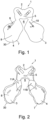
Figure 1 shows a plan view of the front of a life preserver (that will face away from wearer's chest in use), according to the embodiment of the invention; -
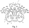
Figure 2 shows a plan view of the rear of a life preserver (that will face the wearer's chest in use), according to the embodiment of the invention; -
Figure 3 shows a sheet of material used to form the life preserver; -
Figures 4 and 5 show the stages in the formation of a chin support according to the embodiment of the invention; -
Figure 6 shows a partial side view of the life preserver, from the outside, including the chin support according to the embodiment of the invention; -
Figure 7 shows a partial side view of the life preserver, from the inside, including the chin support according to the embodiment of the invention; -
Figure 8 shows a plan view of the front of the life preserver fitted to the torso of the wearer; -
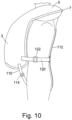
Figure 9 shows a plan view of the rear of the life preserver fitted to the torso of the wearer; and -
Figure 10 shows a side view of the life preserver fitted to the torso of the wearer (the opposite side corresponds). - In the drawings like elements are generally designated with the same reference sign.
- Referring initially to
Figures 1 and 2 , there is shown alife preserver 1, such as a lifejacket. Thelife preserver 1 comprises abody 2 that is generally horse-shoe shaped and is for fitting around a wearer's neck. - The
body 2 comprises first and secondinflatable buoyancy sections second buoyancy sections neck portion 5. The first andsecond buoyancy sections second buoyancy sections neck portion 5, define anaperture 6 for receiving a wearer's head and neck. - The
lifejacket body 2 is formed from first and second layers of material sealed together along a seam 7 (as described below), towards a peripheral edge, to define abody inflation chamber 8. The layers of material protrude from theseam 7 to form anedge 30. - When inflated, each
buoyancy section - The
inflation chamber 8 is connected to aninflation cartridge 9, containing compressed gas, that can be manually or automatically actuated. Following actuation, the inflation cartridge inflates thebody inflation chamber 8. - Each
buoyancy section tube 10 connected to the interior of thebody inflation chamber 8. This allows manual inflation of thebody inflation chamber 8 in the event of failure of theinflation cartridge 9. Eachtube 10 is provided with a non-return valve and a closure cap to prevent water flowing down the tube and into thebody inflation chamber 8. - In use the first and
second buoyancy sections - In use, the first and
second buoyancy sections second buoyancy sections integral chin support second buoyancy sections neck aperture 6. - The
chin support 11A is integral with thefirst buoyancy section 3. Thechin support 11B is integral with thesecond buoyancy section 4. - When the chin support is nested under the wearer's chin, it acts to prevent the first and
second buoyancy sections -
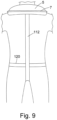
Figure 3 shows a plan view of a first layer of material used to form thelife preserver 1. In order to form thelife preserver 1, a second, substantially identical, layer is placed over the first layer and aligned with the first layer. The first and second layers of material are then heat sealed together along theseam 7. In order to achieve this heat sealing, a layer of heat melt adhesive is provided between the first and second layers of material. The first and second layers of material may be attached by any other suitable method. - The first and second layers of material are a plastic-coated fabric that is gas impermeable. It will be appreciated that any suitable material or method of heat sealing may be used.
- As best shown in
Figure 3 , the chin supports 11A and 11B are formed by generally T-shapedwings outer region 39A of thefirst buoyancy section 3 and anouter region 39B of thesecond buoyancy section 4, respectively. - An inner facing region 41A of the
first buoyancy section 3 has aconnection portion 40A extending therefrom (and are integrally formed therewith). An inner facing region 41B of thesecond buoyancy section 4 has a connection portion 4OB extending therefrom (and are integrally formed therewith). InFigure 3 theconnection portions connection portions - The
life preserver 1 is formed by sealing said first and second layers of material together along theseam 7. The seam extends around the first andsecond buoyancy sections wings connection portions 40A; and theneck portion 5. A singleinflatable chamber 8 is formed within the volume defined by theseam 7. - The
seam 7 extends between thefirst buoyancy section 3 and thefirst connection region 40A to define defines a firstnon-inflated region 42A. The firstnon-inflated region 42A facilitates folding of thefirst connection region 40A with respect to thefirst buoyancy section 3. Similarly, theseam 7 extends between thesecond buoyancy section 4 and thesecond connection region 40B to define defines a secondnon-inflated region 42B. The secondnon-inflated region 42B facilitates folding of the second connection region 4OB with respect to thesecond buoyancy section 4. - The generally T-shaped
wing 38A comprises astem portion 44A that connects to theouter region 39A of thefirst buoyancy section 3. Inflation gas passes from thefirst buoyancy section 3 to the generally T-shapedwing 38A in the channel between theseams 7 in thestem portion 44A. The narrowness of thestem portion 44A facilitates folding of thestem portion 44A - The
stem portion 44A connects to anupper head portion 46A and alower head portion 48A of the generally T-shapedwing 38A. Thelower head portion 48A includes a reducedwidth region 49A, where one side tapers towards the other, and which facilitates folding of the lower head portion 4SA over theupper head portion 46A. - At an upper portion of the
first buoyancy section 3, at or near a junction with theneck portion 5, theseam 7 extends from the outer side inwards and downwardly towards theopening 6. This defines a reduced depth,uninflated region 50A. Theuninflated region 50A facilities rotation of thefirst buoyancy section 3 with respect to theneck portion 5. - The
life preserver 1 is symmetrical about the longitudinal axis (generally parallel to the wearer's spine). The generally T-shapedwing 38B comprises astem portion 44B that connects to theouter region 39B of thesecond buoyancy section 4. Inflation gas passes from thesecond buoyancy section 4 to the generally T-shapedwing 38B in the channel between theseams 7 in thestem portion 44B. The narrowness of thestem portion 44B facilitates folding of thestem portion 44B. Thestem portion 44B connects to anupper head portion 46B and alower head portion 48B of the generally T-shapedwing 38B. The lower head portion includes a reducedwidth region 49B, where one side tapers towards the other, and which facilitates folding of thelower head portion 48B over theupper head portion 46B. At an upper portion of thesecond buoyancy section 4, at or near a junction with the neck portion S, theseam 7 extends from the outer side inwards and downwardly towards theopening 6. This defines a reduced depth, uninflated region SOB. The uninflated region SOB facilities rotation of thesecond buoyancy section 4 with respect to the neck portion S. - The uninflated regions SOA, SOB may overlie the wearer's shoulders in use (the shoulders engaging the rear side of the life preserver 1). The wearer's head/neck passes through the
opening 6 and engages the front side of thelife preserver 1. -
Figures 4 and 5 show the formation of thechin support portions lower head portion 48A of thewing portion 38A is folded at reducedwidth region 49A so that it overlies theupper head portion 46A. The free ends of thelower head portion 48A and theupper head portion 46A are then connected atline 62A, e.g. by welding. - Similarly, the
lower head portion 48B of thewing portion 38B is folded at reducedwidth region 49B so that it overlies theupper head portion 46B. The free ends of thelower head portion 48B and theupper head portion 46B are then connected atline 62B, e.g. by welding. - Secondly, the head (comprising the
upper head portion 46A and alower head portion 48A) of thewing portion 38A is folded alongfold line 64A of thestem 44A. Thelower head portion 48A then overlies thefirst buoyancy section 3 and theconnection portion 40A. The connectedlower head portion 48A andupper head portion 46A atline 62A are then connected to adistal edge 66A of theconnection portion 40A, e.g. by welding. - Similarly, the head (comprising the
upper head portion 46B and alower head portion 48B) of thewing portion 38B is folded alongfold line 64B thestem 44B. Thelower head portion 48B then overlies thesecond buoyancy section 4 and theconnection portion 40B. The connectedlower head portion 48B andupper head portion 46B atline 62B are then connected to adistal edge 66B of theconnection portion 40B, e.g. by welding. - The second step, together with inflation, causes the first and
second buoyancy section neck portion 5, facilitated by theuninflated regions 50A, SOB. The upper faces (as shown inFigure 5 ) of thelower head portions Figure 5 ) of theupper head portions - As the chin supports 11A, 11B have a low volume and depth they are readily deformable, providing for comfort around the neck and chin. The
lower head portions life preserver 1 over the wearer's head. - One or more straps may be attached to the
life preserver 1 and may pass around the torso of the wearer to secure thelifejacket 1 to the wearer. Examples of suitable strap arrangements are described below in relation toFigures 8 ,9 and10 . - As mentioned above, the first and
second buoyancy section second buoyancy sections - The uninflated regions SOA, SOB provide pivot hinges for the 3D shaping of the
life preserver 1. The uninflated regions SOA, SOB overlie the wearer's shoulders in use. When thelife preserver 1 is inflated over the shoulders, uninflated regions SOA, SOB and the larger depth neck section S can sit on the same plane i.e. the uninflated regions SOA, SOB allow a uniform bend to thelife preserver 1 without the shoulder regions collapsing due to twisting (the first andsecond buoyancy sections buoyancy section 3 to twist or rotate clockwise with respect to the neck section S (about an axis generally parallel with the wearer's spine). The uninflated region SOB allows the left-hand side (viewed from the front)buoyancy section 4 to twist or rotate anti-clockwise with respect to the neck section 5 (about an axis generally parallel with the wearer's spine). Theuninflated regions 50A, SOB reduce the tendency for the adjacent inflated region to collapse due to the twisting or rotation. - The chin support may cause the first and
second buoyancy sections second buoyancy sections - The chin support supports the wearer's chin at a relatively large height above the water level.
- The chin support acts to close the wearer's mouth, thereby preventing the wearer from swallowing any water that is channelled towards his mouth. In addition, the chin support tilts the wearer's mouth away from the water.
- In addition, when the chin support is nested under the wearer's chin, it acts to prevent the first and
second buoyancy sections -
Figures 8 ,9 and10 show example arrangements for straps to attach thelife preserver 1 to thewearer 100. - A front strap 102 may releasably connect together the first and
second buoyancy sections right lobe 3, a second portion of the front strap 102 is attached to theleft lobe 4, and abuckle 104 releasably attaches the portions together. - Two crotch straps 110 may releasably connect the first and
second buoyancy sections neck portion 5 via aback strap 112 which extends along the wearer's back. The crotch straps 110 meet between the wearer's legs and connect to theback strap 112. A first one of the crotch straps 110 is attached to theright lobe 3 and a second one of the crotch straps 110 is attached to theleft lobe 4. Theback strap 112 is attached to theneck portion 5. The crotch straps may be opened by operating respective buckles 114. - A
side strap 120 may releasably connect together the first andsecond buoyancy sections side strap 120 is attached to theright lobe 3, a second portion of theside strap 120 is attached to theleft lobe 4, and abuckle 122 releasably attaches the portions together. Theside strap 120 extends around the wearer's back, near the waistline. - The above embodiments are described by way of example. Many variations are possible without departing from the invention.
Claims (11)
- A life preserver comprising first and second buoyancy sections (3, 4) arranged such that, in use, the first and second buoyancy sections (3, 4) lie on opposite sides respectively of a wearer's chest, wherein:said first and second buoyancy sections (3, 4) include respective inner facing regions (41A, 41B) that face one another above respective opposite sides of the wearer's chest, each of the inner facing regions (41A, 41B) having a chin support portion (46A, 46B) connected thereto and each of the chin support portions (46A, 46B) being configured to abut each other substantially at the centre of the wearer's chest in use to form a chin support (11A, 11B) ;each of said first and second buoyancy sections (3, 4) includes an outer region (39A, 39B) at an opposite side thereof to the inner facing region (41A, 41B), wherein each chin support portion (46A, 46B) extends from its corresponding outer region (39A, 39B); and each of the chin support portions (46A, 46B) is folded across the buoyancy section (3, 4) from which it extends.
- The life preserver of claim 1, wherein each of the chin support portions (46A, 46B) include a first part and a second part, the first part being folded over the second part.
- The life preserver of any one of the preceding claims, wherein the abutting chin support portions (46A, 46B) are configured to tend to maintain the inner facing regions (41A, 41B) of the first and second buoyancy sections (3, 4) spaced apart.
- The life preserver of any one of the preceding claims, wherein the first and second buoyancy sections (3, 4) are inflatable.
- The life preserver of claim 4, wherein two sheets of material form the first and second buoyancy sections (3, 4), the sheets of material being selectively joined at connection regions (7) to define an inflatable volume.
- The life preserver of any one of the preceding claims, wherein at least one of the first and second buoyancy sections (3, 4) includes a relatively reduced depth region (50A, 50B) between an upper portion and a lower portion thereof to facilitate relative rotation between the upper portion and the lower portion.
- The life preserver of claim 6, wherein the upper portion is configured to support the wearer's neck or head when inflated in use.
- The life preserver of claim 6 or 7, when dependent on claim 4 or 5, wherein the reduced depth region (50A, 50B) is a non-inflatable region of the buoyancy section (3, 4).
- The life preserver of claim 8, when dependent on claim 5, wherein the non-inflatable region is formed by one of the connection regions (7).
- The life preserver of any one of the preceding claims, wherein the first and second buoyancy sections (3, 4) are substantially symmetrical.
- The life preserver of any one of the preceding claims, wherein the chin support portions are integrally formed with the first and second buoyancy sections.
Applications Claiming Priority (2)
| Application Number | Priority Date | Filing Date | Title |
|---|---|---|---|
| GB1816798.1A GB2578110B (en) | 2018-10-16 | 2018-10-16 | Life preserver |
| PCT/EP2019/078010 WO2020079025A1 (en) | 2018-10-16 | 2019-10-15 | Life preserver |
Publications (2)
| Publication Number | Publication Date |
|---|---|
| EP3867141A1 EP3867141A1 (en) | 2021-08-25 |
| EP3867141B1 true EP3867141B1 (en) | 2024-05-01 |
Family
ID=64394973
Family Applications (1)
| Application Number | Title | Priority Date | Filing Date |
|---|---|---|---|
| EP19787258.3A Active EP3867141B1 (en) | 2018-10-16 | 2019-10-15 | Life preserver |
Country Status (5)
| Country | Link |
|---|---|
| US (1) | US11873068B2 (en) |
| EP (1) | EP3867141B1 (en) |
| AU (1) | AU2019360371B2 (en) |
| GB (1) | GB2578110B (en) |
| WO (1) | WO2020079025A1 (en) |
Families Citing this family (1)
| Publication number | Priority date | Publication date | Assignee | Title |
|---|---|---|---|---|
| GB2632170A (en) * | 2023-07-27 | 2025-01-29 | Henshaw Inflatables Ltd | Lifejacket |
Family Cites Families (9)
| Publication number | Priority date | Publication date | Assignee | Title |
|---|---|---|---|---|
| GB566097A (en) * | 1943-06-07 | 1944-12-13 | Zbigniew Siedlecki | Improvements relating to buoyant suits for use more especially for life-saving purposes |
| US2550562A (en) * | 1948-02-05 | 1951-04-24 | Us Rubber Co | Life preserver |
| DE1213284B (en) * | 1961-12-01 | 1966-03-24 | Bernhardt Appbau G M B H & Co | Lifeguard |
| US4934973A (en) * | 1989-01-11 | 1990-06-19 | Taylor Benjamin A | Life preserver |
| GB9200851D0 (en) * | 1992-01-15 | 1992-03-11 | Air Safety Prod | Improvements relating to life jackets |
| US6776678B2 (en) * | 2000-12-08 | 2004-08-17 | William H. Courtney | Integrated or attached space occupying cephalic restraint collar for improved life jacket performance |
| US7056179B2 (en) * | 2002-05-05 | 2006-06-06 | Courtney William L | Combination inflator and manifold assembly |
| DE502006007983D1 (en) * | 2005-10-26 | 2010-11-11 | Bernhardt Appbau Gmbh U Co | LIFEJACKET |
| GB2480255B (en) * | 2010-05-10 | 2015-12-23 | Survitec Service & Distrib Ltd | A lifejacket with an integral chin support |
-
2018
- 2018-10-16 GB GB1816798.1A patent/GB2578110B/en active Active
-
2019
- 2019-10-15 EP EP19787258.3A patent/EP3867141B1/en active Active
- 2019-10-15 WO PCT/EP2019/078010 patent/WO2020079025A1/en not_active Ceased
- 2019-10-15 AU AU2019360371A patent/AU2019360371B2/en active Active
- 2019-10-15 US US17/309,013 patent/US11873068B2/en active Active
Also Published As
| Publication number | Publication date |
|---|---|
| WO2020079025A1 (en) | 2020-04-23 |
| US11873068B2 (en) | 2024-01-16 |
| US20220009606A1 (en) | 2022-01-13 |
| AU2019360371B2 (en) | 2025-05-22 |
| GB201816798D0 (en) | 2018-11-28 |
| AU2019360371A1 (en) | 2021-05-20 |
| EP3867141A1 (en) | 2021-08-25 |
| GB2578110B (en) | 2022-10-12 |
| GB2578110A (en) | 2020-04-22 |
Similar Documents
| Publication | Publication Date | Title |
|---|---|---|
| US20040033739A1 (en) | Multi-chambered personal survival device and an orally inflated, flush mounted, hybrid bladder | |
| US5382184A (en) | Personal flotation device in the form of an inflatable belt | |
| US4097947A (en) | Inflatable wearable flotation device | |
| US4498882A (en) | Hybrid personal flotation device | |
| US4626221A (en) | Selfinflating life preserver | |
| US5494469A (en) | Inflatable life vest | |
| EP0630336B1 (en) | Improvements relating to life jackets | |
| US9067658B2 (en) | Inflatable swim vest | |
| US3441963A (en) | Inflatable sailing jacket | |
| US5647059A (en) | Inflatable neck seal | |
| US6394866B1 (en) | 1-step safety belt inflatable into a life vest | |
| US1803898A (en) | Nonsinkable bathing suit | |
| US11873068B2 (en) | Life preserver | |
| US4131974A (en) | Flotation stoles | |
| US3441964A (en) | Life jacket | |
| US4865573A (en) | Inflatable life vest of the single-attachment, single-adjustment type | |
| GB2480255A (en) | A lifejacket with an integral chin support | |
| US5785567A (en) | Buoyancy jacket | |
| US4753621A (en) | Inflatable lifejacket | |
| US20180346080A1 (en) | Personal flotation device | |
| US20250058860A1 (en) | Life preserver | |
| EP4497673A2 (en) | Lifejacket | |
| KR102919152B1 (en) | Immersion suit | |
| JP2005343392A (en) | Inflatable life jacket | |
| US20230094472A1 (en) | Life preserver |
Legal Events
| Date | Code | Title | Description |
|---|---|---|---|
| STAA | Information on the status of an ep patent application or granted ep patent |
Free format text: STATUS: UNKNOWN |
|
| STAA | Information on the status of an ep patent application or granted ep patent |
Free format text: STATUS: THE INTERNATIONAL PUBLICATION HAS BEEN MADE |
|
| PUAI | Public reference made under article 153(3) epc to a published international application that has entered the european phase |
Free format text: ORIGINAL CODE: 0009012 |
|
| STAA | Information on the status of an ep patent application or granted ep patent |
Free format text: STATUS: REQUEST FOR EXAMINATION WAS MADE |
|
| 17P | Request for examination filed |
Effective date: 20210408 |
|
| AK | Designated contracting states |
Kind code of ref document: A1 Designated state(s): AL AT BE BG CH CY CZ DE DK EE ES FI FR GB GR HR HU IE IS IT LI LT LU LV MC MK MT NL NO PL PT RO RS SE SI SK SM TR |
|
| DAV | Request for validation of the european patent (deleted) | ||
| DAX | Request for extension of the european patent (deleted) | ||
| GRAP | Despatch of communication of intention to grant a patent |
Free format text: ORIGINAL CODE: EPIDOSNIGR1 |
|
| STAA | Information on the status of an ep patent application or granted ep patent |
Free format text: STATUS: GRANT OF PATENT IS INTENDED |
|
| INTG | Intention to grant announced |
Effective date: 20231127 |
|
| GRAS | Grant fee paid |
Free format text: ORIGINAL CODE: EPIDOSNIGR3 |
|
| GRAA | (expected) grant |
Free format text: ORIGINAL CODE: 0009210 |
|
| STAA | Information on the status of an ep patent application or granted ep patent |
Free format text: STATUS: THE PATENT HAS BEEN GRANTED |
|
| AK | Designated contracting states |
Kind code of ref document: B1 Designated state(s): AL AT BE BG CH CY CZ DE DK EE ES FI FR GB GR HR HU IE IS IT LI LT LU LV MC MK MT NL NO PL PT RO RS SE SI SK SM TR |
|
| REG | Reference to a national code |
Ref country code: GB Ref legal event code: FG4D |
|
| REG | Reference to a national code |
Ref country code: CH Ref legal event code: EP |
|
| REG | Reference to a national code |
Ref country code: IE Ref legal event code: FG4D |
|
| REG | Reference to a national code |
Ref country code: DE Ref legal event code: R096 Ref document number: 602019051497 Country of ref document: DE |
|
| REG | Reference to a national code |
Ref country code: LT Ref legal event code: MG9D |
|
| REG | Reference to a national code |
Ref country code: NL Ref legal event code: MP Effective date: 20240501 |
|
| PG25 | Lapsed in a contracting state [announced via postgrant information from national office to epo] |
Ref country code: IS Free format text: LAPSE BECAUSE OF FAILURE TO SUBMIT A TRANSLATION OF THE DESCRIPTION OR TO PAY THE FEE WITHIN THE PRESCRIBED TIME-LIMIT Effective date: 20240901 |
|
| PG25 | Lapsed in a contracting state [announced via postgrant information from national office to epo] |
Ref country code: BG Free format text: LAPSE BECAUSE OF FAILURE TO SUBMIT A TRANSLATION OF THE DESCRIPTION OR TO PAY THE FEE WITHIN THE PRESCRIBED TIME-LIMIT Effective date: 20240501 |
|
| PG25 | Lapsed in a contracting state [announced via postgrant information from national office to epo] |
Ref country code: FI Free format text: LAPSE BECAUSE OF FAILURE TO SUBMIT A TRANSLATION OF THE DESCRIPTION OR TO PAY THE FEE WITHIN THE PRESCRIBED TIME-LIMIT Effective date: 20240501 Ref country code: HR Free format text: LAPSE BECAUSE OF FAILURE TO SUBMIT A TRANSLATION OF THE DESCRIPTION OR TO PAY THE FEE WITHIN THE PRESCRIBED TIME-LIMIT Effective date: 20240501 |
|
| PG25 | Lapsed in a contracting state [announced via postgrant information from national office to epo] |
Ref country code: GR Free format text: LAPSE BECAUSE OF FAILURE TO SUBMIT A TRANSLATION OF THE DESCRIPTION OR TO PAY THE FEE WITHIN THE PRESCRIBED TIME-LIMIT Effective date: 20240802 |
|
| PG25 | Lapsed in a contracting state [announced via postgrant information from national office to epo] |
Ref country code: PT Free format text: LAPSE BECAUSE OF FAILURE TO SUBMIT A TRANSLATION OF THE DESCRIPTION OR TO PAY THE FEE WITHIN THE PRESCRIBED TIME-LIMIT Effective date: 20240902 |
|
| REG | Reference to a national code |
Ref country code: AT Ref legal event code: MK05 Ref document number: 1682018 Country of ref document: AT Kind code of ref document: T Effective date: 20240501 |
|
| PG25 | Lapsed in a contracting state [announced via postgrant information from national office to epo] |
Ref country code: NL Free format text: LAPSE BECAUSE OF FAILURE TO SUBMIT A TRANSLATION OF THE DESCRIPTION OR TO PAY THE FEE WITHIN THE PRESCRIBED TIME-LIMIT Effective date: 20240501 |
|
| PG25 | Lapsed in a contracting state [announced via postgrant information from national office to epo] |
Ref country code: ES Free format text: LAPSE BECAUSE OF FAILURE TO SUBMIT A TRANSLATION OF THE DESCRIPTION OR TO PAY THE FEE WITHIN THE PRESCRIBED TIME-LIMIT Effective date: 20240501 |
|
| PG25 | Lapsed in a contracting state [announced via postgrant information from national office to epo] |
Ref country code: AT Free format text: LAPSE BECAUSE OF FAILURE TO SUBMIT A TRANSLATION OF THE DESCRIPTION OR TO PAY THE FEE WITHIN THE PRESCRIBED TIME-LIMIT Effective date: 20240501 |
|
| PG25 | Lapsed in a contracting state [announced via postgrant information from national office to epo] |
Ref country code: PL Free format text: LAPSE BECAUSE OF FAILURE TO SUBMIT A TRANSLATION OF THE DESCRIPTION OR TO PAY THE FEE WITHIN THE PRESCRIBED TIME-LIMIT Effective date: 20240501 |
|
| PG25 | Lapsed in a contracting state [announced via postgrant information from national office to epo] |
Ref country code: LV Free format text: LAPSE BECAUSE OF FAILURE TO SUBMIT A TRANSLATION OF THE DESCRIPTION OR TO PAY THE FEE WITHIN THE PRESCRIBED TIME-LIMIT Effective date: 20240501 |
|
| PG25 | Lapsed in a contracting state [announced via postgrant information from national office to epo] |
Ref country code: PT Free format text: LAPSE BECAUSE OF FAILURE TO SUBMIT A TRANSLATION OF THE DESCRIPTION OR TO PAY THE FEE WITHIN THE PRESCRIBED TIME-LIMIT Effective date: 20240902 Ref country code: PL Free format text: LAPSE BECAUSE OF FAILURE TO SUBMIT A TRANSLATION OF THE DESCRIPTION OR TO PAY THE FEE WITHIN THE PRESCRIBED TIME-LIMIT Effective date: 20240501 Ref country code: NO Free format text: LAPSE BECAUSE OF FAILURE TO SUBMIT A TRANSLATION OF THE DESCRIPTION OR TO PAY THE FEE WITHIN THE PRESCRIBED TIME-LIMIT Effective date: 20240801 Ref country code: NL Free format text: LAPSE BECAUSE OF FAILURE TO SUBMIT A TRANSLATION OF THE DESCRIPTION OR TO PAY THE FEE WITHIN THE PRESCRIBED TIME-LIMIT Effective date: 20240501 Ref country code: LV Free format text: LAPSE BECAUSE OF FAILURE TO SUBMIT A TRANSLATION OF THE DESCRIPTION OR TO PAY THE FEE WITHIN THE PRESCRIBED TIME-LIMIT Effective date: 20240501 Ref country code: IS Free format text: LAPSE BECAUSE OF FAILURE TO SUBMIT A TRANSLATION OF THE DESCRIPTION OR TO PAY THE FEE WITHIN THE PRESCRIBED TIME-LIMIT Effective date: 20240901 Ref country code: HR Free format text: LAPSE BECAUSE OF FAILURE TO SUBMIT A TRANSLATION OF THE DESCRIPTION OR TO PAY THE FEE WITHIN THE PRESCRIBED TIME-LIMIT Effective date: 20240501 Ref country code: GR Free format text: LAPSE BECAUSE OF FAILURE TO SUBMIT A TRANSLATION OF THE DESCRIPTION OR TO PAY THE FEE WITHIN THE PRESCRIBED TIME-LIMIT Effective date: 20240802 Ref country code: FI Free format text: LAPSE BECAUSE OF FAILURE TO SUBMIT A TRANSLATION OF THE DESCRIPTION OR TO PAY THE FEE WITHIN THE PRESCRIBED TIME-LIMIT Effective date: 20240501 Ref country code: ES Free format text: LAPSE BECAUSE OF FAILURE TO SUBMIT A TRANSLATION OF THE DESCRIPTION OR TO PAY THE FEE WITHIN THE PRESCRIBED TIME-LIMIT Effective date: 20240501 Ref country code: BG Free format text: LAPSE BECAUSE OF FAILURE TO SUBMIT A TRANSLATION OF THE DESCRIPTION OR TO PAY THE FEE WITHIN THE PRESCRIBED TIME-LIMIT Effective date: 20240501 Ref country code: AT Free format text: LAPSE BECAUSE OF FAILURE TO SUBMIT A TRANSLATION OF THE DESCRIPTION OR TO PAY THE FEE WITHIN THE PRESCRIBED TIME-LIMIT Effective date: 20240501 Ref country code: RS Free format text: LAPSE BECAUSE OF FAILURE TO SUBMIT A TRANSLATION OF THE DESCRIPTION OR TO PAY THE FEE WITHIN THE PRESCRIBED TIME-LIMIT Effective date: 20240801 |
|
| PG25 | Lapsed in a contracting state [announced via postgrant information from national office to epo] |
Ref country code: DK Free format text: LAPSE BECAUSE OF FAILURE TO SUBMIT A TRANSLATION OF THE DESCRIPTION OR TO PAY THE FEE WITHIN THE PRESCRIBED TIME-LIMIT Effective date: 20240501 |
|
| PG25 | Lapsed in a contracting state [announced via postgrant information from national office to epo] |
Ref country code: EE Free format text: LAPSE BECAUSE OF FAILURE TO SUBMIT A TRANSLATION OF THE DESCRIPTION OR TO PAY THE FEE WITHIN THE PRESCRIBED TIME-LIMIT Effective date: 20240501 |
|
| PG25 | Lapsed in a contracting state [announced via postgrant information from national office to epo] |
Ref country code: CZ Free format text: LAPSE BECAUSE OF FAILURE TO SUBMIT A TRANSLATION OF THE DESCRIPTION OR TO PAY THE FEE WITHIN THE PRESCRIBED TIME-LIMIT Effective date: 20240501 |
|
| PG25 | Lapsed in a contracting state [announced via postgrant information from national office to epo] |
Ref country code: RO Free format text: LAPSE BECAUSE OF FAILURE TO SUBMIT A TRANSLATION OF THE DESCRIPTION OR TO PAY THE FEE WITHIN THE PRESCRIBED TIME-LIMIT Effective date: 20240501 Ref country code: SK Free format text: LAPSE BECAUSE OF FAILURE TO SUBMIT A TRANSLATION OF THE DESCRIPTION OR TO PAY THE FEE WITHIN THE PRESCRIBED TIME-LIMIT Effective date: 20240501 |
|
| PG25 | Lapsed in a contracting state [announced via postgrant information from national office to epo] |
Ref country code: SM Free format text: LAPSE BECAUSE OF FAILURE TO SUBMIT A TRANSLATION OF THE DESCRIPTION OR TO PAY THE FEE WITHIN THE PRESCRIBED TIME-LIMIT Effective date: 20240501 |
|
| PG25 | Lapsed in a contracting state [announced via postgrant information from national office to epo] |
Ref country code: SM Free format text: LAPSE BECAUSE OF FAILURE TO SUBMIT A TRANSLATION OF THE DESCRIPTION OR TO PAY THE FEE WITHIN THE PRESCRIBED TIME-LIMIT Effective date: 20240501 Ref country code: SK Free format text: LAPSE BECAUSE OF FAILURE TO SUBMIT A TRANSLATION OF THE DESCRIPTION OR TO PAY THE FEE WITHIN THE PRESCRIBED TIME-LIMIT Effective date: 20240501 Ref country code: RO Free format text: LAPSE BECAUSE OF FAILURE TO SUBMIT A TRANSLATION OF THE DESCRIPTION OR TO PAY THE FEE WITHIN THE PRESCRIBED TIME-LIMIT Effective date: 20240501 Ref country code: EE Free format text: LAPSE BECAUSE OF FAILURE TO SUBMIT A TRANSLATION OF THE DESCRIPTION OR TO PAY THE FEE WITHIN THE PRESCRIBED TIME-LIMIT Effective date: 20240501 Ref country code: DK Free format text: LAPSE BECAUSE OF FAILURE TO SUBMIT A TRANSLATION OF THE DESCRIPTION OR TO PAY THE FEE WITHIN THE PRESCRIBED TIME-LIMIT Effective date: 20240501 Ref country code: CZ Free format text: LAPSE BECAUSE OF FAILURE TO SUBMIT A TRANSLATION OF THE DESCRIPTION OR TO PAY THE FEE WITHIN THE PRESCRIBED TIME-LIMIT Effective date: 20240501 |
|
| REG | Reference to a national code |
Ref country code: DE Ref legal event code: R097 Ref document number: 602019051497 Country of ref document: DE |
|
| PG25 | Lapsed in a contracting state [announced via postgrant information from national office to epo] |
Ref country code: IT Free format text: LAPSE BECAUSE OF FAILURE TO SUBMIT A TRANSLATION OF THE DESCRIPTION OR TO PAY THE FEE WITHIN THE PRESCRIBED TIME-LIMIT Effective date: 20240501 |
|
| PLBE | No opposition filed within time limit |
Free format text: ORIGINAL CODE: 0009261 |
|
| STAA | Information on the status of an ep patent application or granted ep patent |
Free format text: STATUS: NO OPPOSITION FILED WITHIN TIME LIMIT |
|
| 26N | No opposition filed |
Effective date: 20250204 |
|
| PG25 | Lapsed in a contracting state [announced via postgrant information from national office to epo] |
Ref country code: SI Free format text: LAPSE BECAUSE OF FAILURE TO SUBMIT A TRANSLATION OF THE DESCRIPTION OR TO PAY THE FEE WITHIN THE PRESCRIBED TIME-LIMIT Effective date: 20240501 |
|
| REG | Reference to a national code |
Ref country code: DE Ref legal event code: R119 Ref document number: 602019051497 Country of ref document: DE |
|
| REG | Reference to a national code |
Ref country code: CH Ref legal event code: PL |
|
| PG25 | Lapsed in a contracting state [announced via postgrant information from national office to epo] |
Ref country code: MC Free format text: LAPSE BECAUSE OF FAILURE TO SUBMIT A TRANSLATION OF THE DESCRIPTION OR TO PAY THE FEE WITHIN THE PRESCRIBED TIME-LIMIT Effective date: 20240501 |
|
| PG25 | Lapsed in a contracting state [announced via postgrant information from national office to epo] |
Ref country code: DE Free format text: LAPSE BECAUSE OF NON-PAYMENT OF DUE FEES Effective date: 20250501 |
|
| PG25 | Lapsed in a contracting state [announced via postgrant information from national office to epo] |
Ref country code: BE Free format text: LAPSE BECAUSE OF NON-PAYMENT OF DUE FEES Effective date: 20241031 Ref country code: LU Free format text: LAPSE BECAUSE OF NON-PAYMENT OF DUE FEES Effective date: 20241015 |
|
| PG25 | Lapsed in a contracting state [announced via postgrant information from national office to epo] |
Ref country code: FR Free format text: LAPSE BECAUSE OF NON-PAYMENT OF DUE FEES Effective date: 20241031 |
|
| PG25 | Lapsed in a contracting state [announced via postgrant information from national office to epo] |
Ref country code: CH Free format text: LAPSE BECAUSE OF NON-PAYMENT OF DUE FEES Effective date: 20241031 |
|
| REG | Reference to a national code |
Ref country code: BE Ref legal event code: MM Effective date: 20241031 |
|
| PG25 | Lapsed in a contracting state [announced via postgrant information from national office to epo] |
Ref country code: SE Free format text: LAPSE BECAUSE OF FAILURE TO SUBMIT A TRANSLATION OF THE DESCRIPTION OR TO PAY THE FEE WITHIN THE PRESCRIBED TIME-LIMIT Effective date: 20240501 |
|
| PG25 | Lapsed in a contracting state [announced via postgrant information from national office to epo] |
Ref country code: IE Free format text: LAPSE BECAUSE OF NON-PAYMENT OF DUE FEES Effective date: 20241015 |
|
| PGFP | Annual fee paid to national office [announced via postgrant information from national office to epo] |
Ref country code: GB Payment date: 20251001 Year of fee payment: 7 |
|
| PG25 | Lapsed in a contracting state [announced via postgrant information from national office to epo] |
Ref country code: CY Free format text: LAPSE BECAUSE OF FAILURE TO SUBMIT A TRANSLATION OF THE DESCRIPTION OR TO PAY THE FEE WITHIN THE PRESCRIBED TIME-LIMIT; INVALID AB INITIO Effective date: 20191015 |
|
| PG25 | Lapsed in a contracting state [announced via postgrant information from national office to epo] |
Ref country code: HU Free format text: LAPSE BECAUSE OF FAILURE TO SUBMIT A TRANSLATION OF THE DESCRIPTION OR TO PAY THE FEE WITHIN THE PRESCRIBED TIME-LIMIT; INVALID AB INITIO Effective date: 20191015 |