EP3866295A1 - A vehicle electrical system - Google Patents
A vehicle electrical system Download PDFInfo
- Publication number
- EP3866295A1 EP3866295A1 EP20157083.5A EP20157083A EP3866295A1 EP 3866295 A1 EP3866295 A1 EP 3866295A1 EP 20157083 A EP20157083 A EP 20157083A EP 3866295 A1 EP3866295 A1 EP 3866295A1
- Authority
- EP
- European Patent Office
- Prior art keywords
- switch
- inverter
- electrical
- storage system
- electrical storage
- Prior art date
- Legal status (The legal status is an assumption and is not a legal conclusion. Google has not performed a legal analysis and makes no representation as to the accuracy of the status listed.)
- Granted
Links
Images





Classifications
-
- B—PERFORMING OPERATIONS; TRANSPORTING
- B60—VEHICLES IN GENERAL
- B60L—PROPULSION OF ELECTRICALLY-PROPELLED VEHICLES; SUPPLYING ELECTRIC POWER FOR AUXILIARY EQUIPMENT OF ELECTRICALLY-PROPELLED VEHICLES; ELECTRODYNAMIC BRAKE SYSTEMS FOR VEHICLES IN GENERAL; MAGNETIC SUSPENSION OR LEVITATION FOR VEHICLES; MONITORING OPERATING VARIABLES OF ELECTRICALLY-PROPELLED VEHICLES; ELECTRIC SAFETY DEVICES FOR ELECTRICALLY-PROPELLED VEHICLES
- B60L53/00—Methods of charging batteries, specially adapted for electric vehicles; Charging stations or on-board charging equipment therefor; Exchange of energy storage elements in electric vehicles
- B60L53/10—Methods of charging batteries, specially adapted for electric vehicles; Charging stations or on-board charging equipment therefor; Exchange of energy storage elements in electric vehicles characterised by the energy transfer between the charging station and the vehicle
- B60L53/14—Conductive energy transfer
-
- B—PERFORMING OPERATIONS; TRANSPORTING
- B60—VEHICLES IN GENERAL
- B60L—PROPULSION OF ELECTRICALLY-PROPELLED VEHICLES; SUPPLYING ELECTRIC POWER FOR AUXILIARY EQUIPMENT OF ELECTRICALLY-PROPELLED VEHICLES; ELECTRODYNAMIC BRAKE SYSTEMS FOR VEHICLES IN GENERAL; MAGNETIC SUSPENSION OR LEVITATION FOR VEHICLES; MONITORING OPERATING VARIABLES OF ELECTRICALLY-PROPELLED VEHICLES; ELECTRIC SAFETY DEVICES FOR ELECTRICALLY-PROPELLED VEHICLES
- B60L53/00—Methods of charging batteries, specially adapted for electric vehicles; Charging stations or on-board charging equipment therefor; Exchange of energy storage elements in electric vehicles
- B60L53/20—Methods of charging batteries, specially adapted for electric vehicles; Charging stations or on-board charging equipment therefor; Exchange of energy storage elements in electric vehicles characterised by converters located in the vehicle
- B60L53/22—Constructional details or arrangements of charging converters specially adapted for charging electric vehicles
-
- B—PERFORMING OPERATIONS; TRANSPORTING
- B60—VEHICLES IN GENERAL
- B60L—PROPULSION OF ELECTRICALLY-PROPELLED VEHICLES; SUPPLYING ELECTRIC POWER FOR AUXILIARY EQUIPMENT OF ELECTRICALLY-PROPELLED VEHICLES; ELECTRODYNAMIC BRAKE SYSTEMS FOR VEHICLES IN GENERAL; MAGNETIC SUSPENSION OR LEVITATION FOR VEHICLES; MONITORING OPERATING VARIABLES OF ELECTRICALLY-PROPELLED VEHICLES; ELECTRIC SAFETY DEVICES FOR ELECTRICALLY-PROPELLED VEHICLES
- B60L53/00—Methods of charging batteries, specially adapted for electric vehicles; Charging stations or on-board charging equipment therefor; Exchange of energy storage elements in electric vehicles
- B60L53/20—Methods of charging batteries, specially adapted for electric vehicles; Charging stations or on-board charging equipment therefor; Exchange of energy storage elements in electric vehicles characterised by converters located in the vehicle
- B60L53/24—Using the vehicle's propulsion converter for charging
-
- H—ELECTRICITY
- H02—GENERATION; CONVERSION OR DISTRIBUTION OF ELECTRIC POWER
- H02J—ELECTRIC POWER NETWORKS; CIRCUIT ARRANGEMENTS OR SYSTEMS FOR SUPPLYING OR DISTRIBUTING ELECTRIC POWER; SYSTEMS FOR STORING ELECTRIC ENERGY
- H02J7/00—Circuit arrangements for charging or discharging batteries or for supplying loads from batteries
- H02J7/02—Circuit arrangements for charging or discharging batteries or for supplying loads from batteries for charging batteries from AC mains by converters
-
- H—ELECTRICITY
- H02—GENERATION; CONVERSION OR DISTRIBUTION OF ELECTRIC POWER
- H02J—ELECTRIC POWER NETWORKS; CIRCUIT ARRANGEMENTS OR SYSTEMS FOR SUPPLYING OR DISTRIBUTING ELECTRIC POWER; SYSTEMS FOR STORING ELECTRIC ENERGY
- H02J7/00—Circuit arrangements for charging or discharging batteries or for supplying loads from batteries
- H02J7/90—Regulation of charging or discharging current or voltage
-
- H—ELECTRICITY
- H02—GENERATION; CONVERSION OR DISTRIBUTION OF ELECTRIC POWER
- H02J—ELECTRIC POWER NETWORKS; CIRCUIT ARRANGEMENTS OR SYSTEMS FOR SUPPLYING OR DISTRIBUTING ELECTRIC POWER; SYSTEMS FOR STORING ELECTRIC ENERGY
- H02J7/00—Circuit arrangements for charging or discharging batteries or for supplying loads from batteries
- H02J7/90—Regulation of charging or discharging current or voltage
- H02J7/92—Regulation of charging or discharging current or voltage with prioritisation of loads or sources
-
- B—PERFORMING OPERATIONS; TRANSPORTING
- B60—VEHICLES IN GENERAL
- B60L—PROPULSION OF ELECTRICALLY-PROPELLED VEHICLES; SUPPLYING ELECTRIC POWER FOR AUXILIARY EQUIPMENT OF ELECTRICALLY-PROPELLED VEHICLES; ELECTRODYNAMIC BRAKE SYSTEMS FOR VEHICLES IN GENERAL; MAGNETIC SUSPENSION OR LEVITATION FOR VEHICLES; MONITORING OPERATING VARIABLES OF ELECTRICALLY-PROPELLED VEHICLES; ELECTRIC SAFETY DEVICES FOR ELECTRICALLY-PROPELLED VEHICLES
- B60L2210/00—Converter types
- B60L2210/30—AC to DC converters
-
- B—PERFORMING OPERATIONS; TRANSPORTING
- B60—VEHICLES IN GENERAL
- B60L—PROPULSION OF ELECTRICALLY-PROPELLED VEHICLES; SUPPLYING ELECTRIC POWER FOR AUXILIARY EQUIPMENT OF ELECTRICALLY-PROPELLED VEHICLES; ELECTRODYNAMIC BRAKE SYSTEMS FOR VEHICLES IN GENERAL; MAGNETIC SUSPENSION OR LEVITATION FOR VEHICLES; MONITORING OPERATING VARIABLES OF ELECTRICALLY-PROPELLED VEHICLES; ELECTRIC SAFETY DEVICES FOR ELECTRICALLY-PROPELLED VEHICLES
- B60L2210/00—Converter types
- B60L2210/40—DC to AC converters
-
- B—PERFORMING OPERATIONS; TRANSPORTING
- B60—VEHICLES IN GENERAL
- B60L—PROPULSION OF ELECTRICALLY-PROPELLED VEHICLES; SUPPLYING ELECTRIC POWER FOR AUXILIARY EQUIPMENT OF ELECTRICALLY-PROPELLED VEHICLES; ELECTRODYNAMIC BRAKE SYSTEMS FOR VEHICLES IN GENERAL; MAGNETIC SUSPENSION OR LEVITATION FOR VEHICLES; MONITORING OPERATING VARIABLES OF ELECTRICALLY-PROPELLED VEHICLES; ELECTRIC SAFETY DEVICES FOR ELECTRICALLY-PROPELLED VEHICLES
- B60L2220/00—Electrical machine types; Structures or applications thereof
- B60L2220/40—Electrical machine applications
-
- B—PERFORMING OPERATIONS; TRANSPORTING
- B60—VEHICLES IN GENERAL
- B60L—PROPULSION OF ELECTRICALLY-PROPELLED VEHICLES; SUPPLYING ELECTRIC POWER FOR AUXILIARY EQUIPMENT OF ELECTRICALLY-PROPELLED VEHICLES; ELECTRODYNAMIC BRAKE SYSTEMS FOR VEHICLES IN GENERAL; MAGNETIC SUSPENSION OR LEVITATION FOR VEHICLES; MONITORING OPERATING VARIABLES OF ELECTRICALLY-PROPELLED VEHICLES; ELECTRIC SAFETY DEVICES FOR ELECTRICALLY-PROPELLED VEHICLES
- B60L2220/00—Electrical machine types; Structures or applications thereof
- B60L2220/40—Electrical machine applications
- B60L2220/42—Electrical machine applications with use of more than one motor
-
- H—ELECTRICITY
- H02—GENERATION; CONVERSION OR DISTRIBUTION OF ELECTRIC POWER
- H02J—ELECTRIC POWER NETWORKS; CIRCUIT ARRANGEMENTS OR SYSTEMS FOR SUPPLYING OR DISTRIBUTING ELECTRIC POWER; SYSTEMS FOR STORING ELECTRIC ENERGY
- H02J2105/00—Networks for supplying or distributing electric power characterised by their spatial reach or by the load
- H02J2105/30—Networks for supplying or distributing electric power characterised by their spatial reach or by the load the load networks being external to vehicles, i.e. exchanging power with vehicles
- H02J2105/33—Networks for supplying or distributing electric power characterised by their spatial reach or by the load the load networks being external to vehicles, i.e. exchanging power with vehicles exchanging power with road vehicles
- H02J2105/37—Networks for supplying or distributing electric power characterised by their spatial reach or by the load the load networks being external to vehicles, i.e. exchanging power with vehicles exchanging power with road vehicles exchanging power with electric vehicles [EV] or with hybrid electric vehicles [HEV]
-
- H—ELECTRICITY
- H02—GENERATION; CONVERSION OR DISTRIBUTION OF ELECTRIC POWER
- H02J—ELECTRIC POWER NETWORKS; CIRCUIT ARRANGEMENTS OR SYSTEMS FOR SUPPLYING OR DISTRIBUTING ELECTRIC POWER; SYSTEMS FOR STORING ELECTRIC ENERGY
- H02J2207/00—Details of circuit arrangements for charging or discharging batteries or supplying loads from batteries
- H02J2207/40—Details of circuit arrangements for charging or discharging batteries or supplying loads from batteries adapted for charging from various sources, e.g. AC, DC or multivoltage
-
- Y—GENERAL TAGGING OF NEW TECHNOLOGICAL DEVELOPMENTS; GENERAL TAGGING OF CROSS-SECTIONAL TECHNOLOGIES SPANNING OVER SEVERAL SECTIONS OF THE IPC; TECHNICAL SUBJECTS COVERED BY FORMER USPC CROSS-REFERENCE ART COLLECTIONS [XRACs] AND DIGESTS
- Y02—TECHNOLOGIES OR APPLICATIONS FOR MITIGATION OR ADAPTATION AGAINST CLIMATE CHANGE
- Y02T—CLIMATE CHANGE MITIGATION TECHNOLOGIES RELATED TO TRANSPORTATION
- Y02T10/00—Road transport of goods or passengers
- Y02T10/60—Other road transportation technologies with climate change mitigation effect
- Y02T10/70—Energy storage systems for electromobility, e.g. batteries
-
- Y—GENERAL TAGGING OF NEW TECHNOLOGICAL DEVELOPMENTS; GENERAL TAGGING OF CROSS-SECTIONAL TECHNOLOGIES SPANNING OVER SEVERAL SECTIONS OF THE IPC; TECHNICAL SUBJECTS COVERED BY FORMER USPC CROSS-REFERENCE ART COLLECTIONS [XRACs] AND DIGESTS
- Y02—TECHNOLOGIES OR APPLICATIONS FOR MITIGATION OR ADAPTATION AGAINST CLIMATE CHANGE
- Y02T—CLIMATE CHANGE MITIGATION TECHNOLOGIES RELATED TO TRANSPORTATION
- Y02T10/00—Road transport of goods or passengers
- Y02T10/60—Other road transportation technologies with climate change mitigation effect
- Y02T10/7072—Electromobility specific charging systems or methods for batteries, ultracapacitors, supercapacitors or double-layer capacitors
Definitions
- the present disclosure relates to a vehicle electrical system and to a method for charging an electrical storage system of a vehicle electrical system.
- the vehicle electrical system and associated method according to the disclosure can be implemented in a vehicle, such as an electric car or a hybrid electric car.
- vehicle electrical system and associated method according to the disclosure is not restricted to this particular vehicle, but may alternatively be installed or implemented in another type of vehicle, such as a truck, a bus, a rail vehicle, a flying vehicle, a marine vessel, an off-road vehicle, a mining vehicle, an agriculture vehicle, a working vehicle such as a wheel loader or excavator, a forest vehicle such as harvesters or forwarders, a motorcycle or the like.
- document US 2015/0231978 A1 discloses an electric system for charging a battery of a plug-in vehicle having dual electrical motors and dual inverters, wherein the inverters are used for charging the battery and wherein the charging current is made to alternate between the first and second motors for preventing motor rotation during charge transfer.
- An object of the present disclosure is to provide a vehicle electrical system and method for charging an electrical storage system of a vehicle electrical system, where the previously mentioned problems are avoided. This object is at least partly achieved by the features of the independent claims.
- a vehicle electrical system comprising an electrical storage system, a first multiphase electrical machine having a plurality of stator windings, a first inverter connected to the electrical storage system and to the first multiphase electrical machine, wherein the first inverter has a plurality of switch legs with switches, a second multiphase electrical machine having a plurality of stator windings, a second inverter connected to the electrical storage system and to the second multiphase electrical machine, wherein the second inverter has a plurality of switch legs with switches, a terminal having a plurality of poles and configured for receiving single-phase AC or multi-phase AC or DC from a vehicle external charging source, a first conductive line connecting a first pole of the terminal with a first switch leg of the first inverter, a second conductive line connecting a second pole of the terminal with a first switch leg of the second inverter, a first inductor arranged in one of the first and second conductive line, and a control system
- a method for charging an electrical storage system of a vehicle electrical system comprises the steps of connecting a first inverter to a first multiphase electrical machine having a plurality of stator windings and to the electrical storage system, wherein the first inverter has a plurality of switch legs with switches, connecting a second inverter to a second multiphase electrical machine having a plurality of stator windings and to the electrical storage system, wherein the second inverter has a plurality of switch legs with switches, connecting a first pole of a terminal with a first switch leg of the first inverter via a first conductive line, connecting a second pole of the terminal with a first switch leg of the second inverter via a second conductive line, providing a first inductor in one of the first and second conductive lines, connecting the terminal having a plurality of poles to a vehicle external charging source configured for supplying single-phase AC or multi-phase AC or DC, and controlling operation of the switches of the
- buck mode is simplified because an appropriate and sufficiently large inductance in henry (H) of the buck/boost circuit inductor can be easily obtained by merely selecting an appropriate inductor element, such as a coil, and install this in the first and/or second conductive line.
- the size of the inductor can also be selected independent on the stator winding design of the electric machines.
- electrical machines with relatively small inductance may be used in the vehicle electric circuit without negative effect on filtering, step-up and/or step-down operating performance.
- the dual use of the existing inverters i.e.
- the control system when the control system is configured for charging the electrical storage system using electrical energy supplied from the vehicle external charging source in a voltage step-up mode, the control system is configured to operate a first switch of the first switch leg of the first inverter with alternating on and off periods, such that a charging current during an on-period flows from the vehicle external charging source, through the first conductive line, the first switch of the first switch leg of the first inverter, an intrinsic or extrinsic reverse diode associated with a first switch of the first switch leg of the second inverter, the second conductive line, the first inductor, and back to the vehicle external charging source, while bypassing the electrical storage system, and such that a charging current during an off-period flows from a negative pole of the electrical storage system, through the intrinsic or extrinsic reverse diode associated with the first switch of the first switch leg of the second inverter, the second conductive line, the first inductor, the vehicle external charging source, the first conductive line, an intrinsic or extrin
- the control system selectively controls operation of the first switch leg of the first inverter and the first switch leg of the second inverter, such that electric current flow alternates between: flowing through the first switch of the first switch leg of the first inverter for charging the electrical storage system during a first supply voltage polarity state, and flowing through the first switch of the first switch leg of the second inverter for charging the electrical storage system during a second supply voltage polarity state.
- both the positive and negative polarity phase of an AC supply may be used for efficient charging of the vehicle electrical system.
- the vehicle electrical system further comprises a first supply switch arranged in one of the first and second conductive lines and configured for selectively opening and closing said first or second conductive line, and a step-down switch operatively connected to the first and second conductive lines and configured for selectively opening and closing a connection between said first or second conductive lines, wherein the first supply switch, the step-down switch and the first inductor are arranged to allow current flow between a portion of the first conductive line and a portion of the second conductive line via the step-down switch and the first inductor when the first supply switch is in an open state.
- the possibility of operating the vehicle electrical system in a voltage step-down mode makes the system more flexible in terms of charging voltage level.
- control system is operatively coupled to the first supply switch and the step-down switch and configured for controlling operation thereof.
- a certain level of joint control of the inverters, the supply switch and the step-down switch is typically required.
- control system controlling operation of also the supply switch and the step-down switch, a more cost-efficient system is accomplished.
- control system when the control system is configured for charging the electrical storage system using electrical energy supplied from the vehicle external charging source in a voltage step-down mode, the control system is configured to operate the first supply switch and the step-down switch synchronised and with alternating on and off periods.
- control system when the control system is configured for charging the electrical storage system using electrical energy supplied from the vehicle external charging source in a voltage step-down mode, the control system is configured to set the first supply switch in a closed state when the step-down switch is set in an open state, and oppositely.
- control system when the control system is configured for charging the electrical storage system using electrical energy supplied from the vehicle external charging source in a voltage step-down mode, the control system is configured to keep all switches of the first and second inverters in an open state.
- the control system when the control system is configured for charging the electrical storage system using electrical energy supplied from the vehicle external charging source in a voltage step-down mode, the control system is configured to operate the first supply switch and the step-down switch, such that a charging current during an on-period of the supply switch flows from a negative pole of the electrical storage system, through the intrinsic or extrinsic reverse diode associated with a first switch of the first switch leg of the second inverter, the second conductive line, the first inductor, the vehicle external charging source, the first conductive line, an intrinsic or extrinsic reverse diode associated with a second switch of the first switch leg of the first inverter, and to a positive pole of the electrical storage system.
- a straight-forward and easily implemented step-down solution is accomplished, that also can be implemented without changing or customizing the design or structure of the inverters and/or electrical machines.
- the control system when the control system is configured for charging the electrical storage system using electrical energy supplied from the vehicle external charging source in a voltage step-down mode, the control system is configured to operate the first supply switch and the step-down switch, such that a charging current during an on-period of the step-down switch flows from a negative pole of the electrical storage system, through the intrinsic or extrinsic reverse diode associated with a first switch of the first switch leg of the second inverter, the second conductive line, the first inductor, the step-down switch, the first conductive line, an intrinsic or extrinsic reverse diode associated with a second switch of the first switch leg of the first inverter, and to a positive pole of the electrical storage system.
- a straight-forward and easily implemented step-down solution is accomplished, that also can be implemented without changing or customizing the design or structure of the inverters and/or electrical machines.
- the control system when the control system is configured for charging the electrical storage system using AC electrical energy supplied from the vehicle external charging source in a voltage step-down mode, the control system is configured to operate the first supply switch and the step-down switch, such that a charging current alternates between: flowing through the intrinsic or extrinsic reverse diode associated with a second switch of the first switch leg of the first inverter and an intrinsic or extrinsic reverse diode associated with a first switch of the first switch leg of the second inverter for charging the electrical storage system during a first supply voltage polarity state; and flowing through the intrinsic or extrinsic reverse diode associated with a second switch of the first switch leg of the second inverter and an intrinsic or extrinsic reverse diode associated with a first switch of the first switch leg of the first inverter for charging the electrical storage system during a second supply voltage polarity state.
- the vehicle electrical system further comprises a third multiphase electrical machine having a plurality of stator windings, a third inverter connected to the electrical storage system and to the third multiphase electrical machine, wherein the third inverter has a plurality of switch legs with switches, a third conductive line connecting a third pole of the terminal with a first switch leg of the third inverter, a second inductor arranged in the second conductive line, a third inductor arranged in the third conductive line, wherein the first inductor is arranged in the first conductive line, and wherein the control system operatively coupled to each of the first, second and third inverters and configured for controlling operation of the switches of the first, second and third inverters for preventing charging current from passing through any of the stator windings of the first, second and third multiphase electrical machines during three-phase charging of the electrical storage system from the vehicle external charging source.
- Three-phase AC for charging of the electrical storage system generally enables significantly faster and more powerful charging than single phase AC charging.
- the first supply switch and the step-down switch are located on a common circuit board separate from the first and second inverters.
- the terminal is configured for receiving single-phase AC from the vehicle external charging source, wherein the vehicle electrical system comprises a first supply switch arranged in the first conductive line and configured for selectively opening and closing said first conductive line, and a second supply switch arranged in the second conductive line and configured for selectively opening and closing said second conductive line.
- Two supply switches one for the phase line and one for the neutral line of the single phase AC, provides more safety against unintentional short circuiting or the like.
- the terminal is configured for receiving three-phase AC from the vehicle external charging source
- the vehicle electrical system comprises a first supply switch arranged in the first conductive line and configured for selectively opening and closing said first conductive line, a second supply switch arranged in the second conductive line and configured for selectively opening and closing said second conductive line, and a third supply switch arranged in the third conductive line and configured for selectively opening and closing said third conductive line.
- Three supply switches, one for each phase of a three-phase AC supply provides more safety against unintentional short circuiting or the like.
- the first conductive line is attached to the first switch leg or to a conductive line connecting the first switch leg with a stator winding of the first multiphase electrical machine
- the second conductive line is attached to the second switch leg or to a conductive line connecting the second switch leg with a stator winding of the second multiphase electrical machine.
- the first conductive line is connected to the first inverter, or the first multiphase electrical machine, or an intermediate element operatively connecting the first inverter with the first multiphase electrical machine, such that a charging current supplied via the first conductive line may reach the first inverter without passing through a stator winding of the first multiphase electrical machine
- the second conductive line is connected to the second inverter, or the second multiphase electrical machine, or an intermediate element operatively connecting the second inverter with the second multiphase electrical machine, such that a charging current supplied via the second conductive line may reach the second inverter without passing through a stator winding of the second multiphase electrical machine.
- the first inductor is an individual element separate from the first and second multiphase electrical machines.
- the first conductive line is configured for being connected to a phase line of a single phase AC supply
- the second conductive line is configured for being connected to a neutral line of the single phase AC supply
- the method further comprises, when charging the electrical storage system using electrical energy supplied from the vehicle external charging source in a voltage step-up mode, operating a first switch of the first switch leg of the first inverter with alternating on and off periods, such that a charging current during an on-period flows from the vehicle external charging source, through the first conductive line, the first switch of the first switch leg of the first inverter, an intrinsic or extrinsic reverse diode associated with a first switch of the first switch leg of the second inverter, the second conductive line, the first inductor, and back to the vehicle external charging source, while bypassing the electrical storage system, and such that a charging current during an off-period flows from a negative pole of the electrical storage system, through the intrinsic or extrinsic reverse diode associated with the first switch of the first switch leg of the second inverter, the second conductive line, the first inductor, the vehicle external charging source, the first conductive line, an intrinsic or extrinsic reverse diode associated
- the method further comprises: providing a first supply switch in one of the first and second conductive lines and configured for selectively opening and closing said first or second conductive line, and providing a step-down switch operatively connected to the first and second conductive lines and configured for selectively opening and closing a connection between said first or second conductive line, wherein the first supply switch, the step-down switch and the first inductor are arranged to allow current flow between the first and second conductive lines via the step-down switch and the first inductor when the first supply switch is in an open state. Operation of the vehicle electrical system in a step-down mode provides a more flexible system with a wider field of application.
- the method further comprises charging the electrical storage system using electrical energy supplied from the vehicle external charging source in a voltage step-down mode by operating the first supply switch and the step-down switch, such that a charging current during an on-period of the supply switch flows from a negative pole of the electrical storage system, through the intrinsic or extrinsic reverse diode associated with a first switch of the first switch leg of the second inverter, the second conductive line, the first inductor, the vehicle external charging source, the first conductive line, an intrinsic or extrinsic reverse diode associated with a second switch of the first switch leg of the first inverter, and to a positive pole of the electrical storage system, and such that a charging current during an on-period of the step-down switch flows from a negative pole of the electrical storage system, through the intrinsic or extrinsic reverse diode associated with a first switch of the first switch leg of the second inverter, the second conductive line, the first inductor, the step-down switch, the first
- the method further comprises charging the electrical storage system using electrical energy supplied from the vehicle external charging source in a voltage step-down mode by operating the first supply switch and the step-down switch synchronised and with alternating on and off periods. Operation of the vehicle electrical system in a step-down mode provides a more flexible system with a wider field of application.
- the method further comprises charging the electrical storage system using electrical energy supplied from the vehicle external charging source in a voltage step-down mode by alternately setting the first supply switch in a closed state when the step-down switch is set in an open state, and oppositely. Operation of the vehicle electrical system in a step-down mode provides a more flexible system with a wider field of application.
- the method further comprises charging the electrical storage system using electrical energy supplied from the vehicle external charging source in a voltage step-down mode by keeping all switches of the first and second inverters in an open state. Operation of the vehicle electrical system in a step-down mode provides a more flexible system with a wider field of application.
- the method further comprising supplying single phase AC from the vehicle external charging source, and controlling operation of the first supply switch and the step-down switch, such that a charging current in a voltage step-down mode alternates between: flowing through the intrinsic or extrinsic reverse diode associated with a second switch of the first switch leg of the first inverter and an intrinsic or extrinsic reverse diode associated with a first switch of the first switch leg of the second inverter for charging the electrical storage system during a first supply voltage polarity state; and flowing through the intrinsic or extrinsic reverse diode associated with a second switch of the first switch leg of the second inverter and an intrinsic or extrinsic reverse diode associated with a first switch of the first switch leg of the first inverter for charging the electrical storage system during a second supply voltage polarity state. Operation of the vehicle electrical system in a step-down mode provides a more flexible system with a wider field of application.
- the method further comprises: connecting a third inverter to a third multiphase electrical machine having a plurality of stator windings and to the electrical storage system, wherein the third inverter has a plurality of switch legs with switches, connecting a third pole of a terminal with a first switch leg of the third inverter via a third conductive line, providing the first inductor in the first conductive line, providing a second inductor in the second conductive line, providing a third inductor in the third conductive line, connecting the terminal having a plurality of poles to a vehicle external charging source configured for supplying three-phase AC, and controlling operation of the switches of the first, second and third inverters for preventing charging current from passing through any of the stator windings of the first, second and third multiphase electrical machines during transfer of electrical charge from the vehicle external charging source to the electrical storage system.
- Three-phase charging supply generally results in significantly increased charging speed and reduced load on individual cables and fuses of the supply grid.
- the vehicle electrical system according to the present disclosure is configured for being implemented in a hybrid electric vehicle or a full electric vehicle, such as a car.
- FIG. 1 schematically shows a side-view of an example type of vehicle 1 that may be implemented with the vehicle electrical system.
- the electrical vehicle 1 is here illustrated in form of a car having front wheels 2a, rear wheels 2b, a passenger compartment 3, luggage compartment 4 and a vehicle powertrain including at least two electrical propulsion motors 5a, 5b, such as two multi-phase AC motors or two DC motors.
- the vehicle powertrain 5 further comprises an electrical storage system 6, such as for example a battery or a combination of battery and a capacitor, for vehicle propulsion.
- an electrical storage system 6 such as for example a battery or a combination of battery and a capacitor, for vehicle propulsion.
- the vehicle may additionally include for example a terminal 7 configured for receiving an external charging connector for charging of the electrical storage system.
- the terminal 7 may advantageously be accessible from the outside of the vehicle 1.
- the vehicle powertrain 5 may additionally include for example a combustion engine or a fuel cell.
- an individual and separate On-board Charger is typically used for charging the electrical storage system of the vehicle.
- a conventional OBC is typically connected to a terminal for connection with the grid, and to the electrical storage system for charging the electrical storage system with power from the grid during for example vehicle parking.
- the OBC typically includes a rectifier for providing AC/DC conversion of the supplied single phase AC before charging the electrical storage system with DC.
- the OBC may be omitted and the first and second inverters, which are normally merely used for powering the electrical machines 5a, 5b and vehicle braking regeneration, are here provided with dual functionality by using the first and second inverters 9a, 9b also for charging of the electrical storage system 6 using electrical energy from the grid, i.e. from the vehicle external charging source.
- the vehicle electrical system may comprise a vehicle on-board electrical storage system 6, a first multiphase electrical machine 5a having a plurality of stator windings 8, a first inverter 9a connected to the electrical storage system 6 and to the first multiphase electrical machine 5a, wherein the first inverter 9a has a plurality of switch legs 10, 11, 12 with switches 10a, 10b, 11a, 11b, 12a, 12b.
- the vehicle electrical system further comprises a second multiphase electrical machine 5b having a plurality of stator windings 13, a second inverter 9b connected to the electrical storage system 6 and to the second multiphase electrical machine 5b, wherein the second inverter 9b has a plurality of switch legs 14, 15, 16 with switches 14a, 14b.
- the vehicle electrical system further comprises a terminal 7 having a plurality of poles and configured for receiving single-phase AC or multi-phase AC or DC from a vehicle external charging source 17, a first conductive line 18 connecting a first pole of the terminal 7 with a first switch leg 10 of the first inverter 9a, a second conductive line 19 connecting a second pole of the terminal 7 with a first switch leg 14 of the second inverter 9b, and a first inductor 20 arranged in one of the first and second conductive lines 18, 19.
- the vehicle electrical system additionally comprises a control system 21 operatively coupled to the first and second inverters 9a, 9b and configured for controlling operation of the switches of the first and second inverters 9a, 9b for preventing a charging current from passing through any of the stator windings 8, 13 of the first and second multiphase electrical machines 5a, 5b during transfer of electrical charge from the vehicle external charging source 17 to the electrical storage system 6.
- the first inductor 20 is thus an individual element separate from the first and second multiphase electrical machines 5a, 5b.
- the electrical storage system 6 may include a high-voltage battery composed of for example lithium-ion battery cells, lithium-sulphur battery cells, or solid-state battery cells, or the like.
- the high-voltage battery may for example have a rated voltage level in the range of 100V - 1500V.
- the battery capacity in terms of kWh depends on factors such as whether the vehicle is a hybrid vehicle having an additional power source, such as a combustion engine, or whether the vehicle is a pure electric vehicle, and the desired operating range, etc.
- the capacity may for example be about 10 - 150 kWh.
- the electrical storage system 6 may include a battery nominal output voltage of for example about of 24V - 59V, in particular 24V or 48V.
- the first and second multiphase electrical machines 5a, 5b may for example be three-phase, five-phase, or seven-phase electrical machines, or the like.
- a three-phase electrical machine may for example have three stator windings, each divided in two halves that are arranged on opposite sides in the stator. The three stator windings may then be disposed 120 degrees apart from each other, and each stator winding may then be deemed having two magnetic poles, i.e. a three-phase two-pole electrical machine. However, the stator windings may alternatively be distributed into four sections, wherein each section is displaced 90 degrees apart from each other. Such a stator winding is deemed having four poles, i.e. a three-phase four-pole electrical machine. Other stator winding arrangements are possible, such as six-pole arrangement, or the like.
- the first and second electrical machines 5a, 5b may for example be permanent magnet synchronous motors or AC induction motors or switched reluctance motors.
- each of the first and second inverters 9a, 9b has three switch legs, i.e. a first switch leg 10, 14, and second switch leg 11, 15 and a third switch leg 12, 16, all connected in parallel.
- Each of the switch legs 10, 11, 12, 14, 15, 16 of the first and second inverters 9a, 9b is supplied with DC from the electrical storage system 6 and the control system may then control the switches to execute appropriate switching operation of the inverter switches 10a, 10b, 11a, 11b, 12a, 12b, 14a, 14b for providing a phase-shifted output voltage to the stator windings 8, 13 of first and second electrical machines 5a, 5b that has more or less a three-phase sinusoidal operating characteristic.
- Each switch leg 10, 11, 12, 14, 15, 16 may have two switches, e.g. a first switch 10a, 11a, 12a, 14a and a second switch 10b, 11b, 12b, 14b.
- a first stator winding 8, 13 of the first and second electrical machines 5a, 5b may be connected to the first switch leg 10 14, between the first and second switches 10a, 10b, 14a, 14b of the first and second inverter 9a, 9b, respectively.
- a second stator winding 8, 13 of the first and second electrical machines 5a, 5b may be connected to the second switch leg 11, 15, between the first and second switches 11 a, 11b of the first and second inverters 9a, 9b, respectively.
- a third stator winding 8, 13 of the first and second electrical machines 5a, 5b may be connected to the third switch leg 12, 14, between the first and second switches 12a, 12b of the first and second inverters 9a, 9b, respectively.
- the switches 10a, 10b, 11a, 11b, 12a, 12b, 14a, 14b may for example be power transistors for controlling torque and/or speed of the first and second multiphase electrical machine.
- the switches may be Insulated Gate Bipolar Transistor (IGBTs) or MOSFETs.
- Each of the switches 10a, 10b, 11 a, 11b, 12a, 12b, 14a, 14b of the first and second inverters 9a, 9b is provided with a parallel-connected reverse diode 10c 10d, 14c, 14d, also known as freewheeling diode, body diode or snubber diode.
- the reverse diode may for example be an intrinsic diode, i.e. a reverse diode functionality.
- MOSTFET types transistors typically include intrinsic reverse diode functionality due to their design and structure.
- some IGBTs generally do not have such intrinsic reverse diodes and may then instead be provided with an extrinsic reverse diode, i.e.
- MOSFET transistors may be provided with an extrinsic reverse diode. Reverse diodes are needed for avoiding that large negative voltage may build up over the transistor when switching an inductive load, because an inductive load typically generate a large negative voltage during negative current changes, thereby potentially destroying the transistor.
- the terminal 7 may for example have three poles, e.g. phase pole, neutral pole and earth pole, as schematically illustrated in figure 2 , for supplying single phase AC to the vehicle.
- the first conductive line 18 may be connected to a phase pole of the terminal 7, and the second conductive line 19 may be connected to the neutral pole of the terminal 7.
- Some additional poles for communication between the vehicle external charging source 17 and vehicle electrical system may be provided.
- the earth pole may be connected to an earth point 22 of the vehicle, such as the metal chassis or the like.
- the terminal 7 may for example have five poles, e.g. first phase pole, second phase pole, third phase pole, neutral pole and earth pole.
- the first and second conductive lines 18, 19 for connecting the terminal 7 with the first and seconds inverters 9a, 9b may be composed of a single conductor or a plurality of interconnected conductors.
- the control system 21 may for example be composed of a single electronic control unit (ECU), as schematically illustrated in figure 2 , or alternatively be composed of a distributed control system having a plurality of interconnected control units, such as for example a first inverter control unit and a second inverter control unit, each inverter control unit being controlled by a common powertrain control unit.
- ECU electronice control unit
- a distributed control system having a plurality of interconnected control units, such as for example a first inverter control unit and a second inverter control unit, each inverter control unit being controlled by a common powertrain control unit.
- the control unit 21 is configured for controlling operation of the switches 10a, 10b, 11a, 11b, 12a, 12b, 14a, 14b of the first and second inverters 9a, 9b for preventing a charging current from passing through any of the stator windings 8, 13 of the first and second multiphase electrical machines 5a, 5b during transfer of electrical charge from the vehicle external charging source 17 to the electrical storage system 6. This is accomplished by appropriate opening and closing of the first switch 10a, 14a of each first leg 10, 14, i.e. the switching leg 10, 14 that is connected to the first and second conductive lines 18, 19.
- control unit 21 is configured for controlling operation of said switches 10a, 10b, 11a, 11b, 12a, 12b, 14a, 14b for preventing said charging current from passing through any of said stator windings 8, 13, in certain operating conditions a relatively small charging current may nevertheless in fact pass through some of said stator windings 8, 13. For example, during time periods of actual charging of the electrical storage system, i.e.
- a minor current may possibly simultaneously, depending on polarity, flow through the first or second conductive line 18, 19 and pass through the stator windings of the first or second electrical machine 5a, 5b and through the reverse diodes of the of the second and/or third switch legs of the inverters 9a, 9b.
- this minor current is typically significantly smaller due to the impedance of said stator windings, and is therefore herein deemed virtually non-existing.
- charging of said common on-board electrical storage system may be accomplished without charging current passing through the stator windings of the first and second electrical machines, while using the inverters for both driving the electrical motors and for charging of the on-board electrical storage system.
- the first conductive line 18 connects the terminal 7 with the first switch leg 10 of the first inverter 9a
- the second conductive line 19 connects the terminal 7 with the first switch leg 14 of the second inverter 9b.
- the first conductive line 18 connects the terminal 7 with the first switch leg 10 of the first inverter 9a at a location between the first and second switches 10a, 10b of the first switch leg 10 of the first inverter 9a
- the second conductive line 19 connects the terminal 7 with the first switch leg 14 of the second inverter 9b at a location between the first and second switches 14a, 14b of the first switch leg 14 of the second inverter 9b.
- first and second conductive lines 18, 19 may be attached to directly to said first switch legs 10, 14, respectively, or indirectly via another conductor.
- the first conductive line 18 may be attached to the first switch leg 10 of the first inverter 9a or to a first conductive line 24 connecting the first switch leg 10 with a stator winding 8 of the first multiphase electrical machine 5a
- the second conductive line 19 may be attached to the first switch leg 14 of the second inverter 9b or to a second conductive line 25 connecting the first switch leg 14 with a stator winding 13 of the second multiphase electrical machine 5b.
- first conductive line 24 may be deemed corresponding to an intermediate element operatively connecting the first switch leg 10 of the first inverter 9a with a stator winding 8 of the first multiphase electrical machine 5a
- second conductive line 25 may be deemed corresponding to an intermediate element operatively connecting a first switch leg 14 of the second inverter 9b with a stator winding 13 of the second multiphase electrical machine.
- first conductive line 18 may be attached to said first switch leg 10 or said first conductive line 24 at a first connection point 26 located outside of a casing of the first inverter 9a and outside of a casing of the first electrical motor 5a, because thereby conventional, off the shelf inverters, may be used, thereby avoiding the need for customized design and thus enabling reduced cost.
- the plurality of stator windings of each of the first and second electric motors 5a, 5b may for example be arranged in star connection having a common neutral point 29, as illustrated in figure 2 , or in a delta connection, or the like.
- the external charging connector 23 is connected to the vehicle external charging source 17, i.e. an external grid 17, such as single phase AC supply or DC supply.
- a voltage step-up conversion of the supply voltage may be accomplished. This is for example useful when the voltage level of the electrical storage system is higher than a peak voltage of an AC supply, or higher than a DC supply voltage. For example, charging of a 400V battery by means of 230V or 120V AC grid supply is not possible without a voltage step-up conversion, also commonly referred to as boost conversion. Voltage step-up conversion is accomplished by means of the first inductor 20 in combination with appropriate switching control of the switches of the first and second inverters 9a, 9b in combination with for example appropriate pulse width modulation, or the like, for attaining the desired charging voltage level.
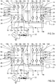
- figure 3a shows the path of a charging current during a switch on-period in a first supply voltage polarity state
- figure 3b shows the path of a charging current during a switch off-period in said first supply voltage polarity state
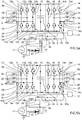
- figure 3c shows the path of a charging current during a switch on-period in a second supply voltage polarity state
- figure 3d shows the path of a charging current during a switch off-period in said second supply voltage polarity state.
- the control system 21 when the control system 21 is configured for charging the electrical storage system 6 using electrical energy supplied from the vehicle external charging source 17 in a voltage step-up mode, the control system 21 is configured to operate a first switch 10a of the first switch leg 10 of the first inverter 9a with alternating on and off periods, such that a charging current during an on-period of said first switch 10a flows from the vehicle external charging source 17, through the first conductive line 18 and an associated the first inductor 20, the first switch 10a of the first switch leg 10 of the first inverter 9a, an intrinsic or extrinsic reverse diode 14c associated with a first switch 14a of the first switch leg 14 of the second inverter 9b, the second conductive line 19, and back to the vehicle external charging source 17, while bypassing the electrical storage system 6.
- first inductor may alternatively be arranged within the second conductive line 19. This apply for all embodiments described within the present disclosure.
- the first switch 10a is in a closed state, i.e. conductive state, resulting in an increase in the charging current flowing through the first inductor 20, such that energy starts to accumulate in said first inductor 20.
- a closed state i.e. conductive state
- an emf is generated, which acts to oppose the increase in the current.
- work must be performed against this emf by the vehicle external charging source 17 in order to establish the current in the first inductor 20.
- the accumulated energy of the first inductor 20 is actually stored in terms of a growing magnetic field generated by the current flowing through the first inductor 20.
- said first switch 10a is an open state, i.e. non-conductive state.
- the charging voltage from the vehicle external charging source 17 combines and collaborate with the stored energy in the first inductor 20, thereby increasing the total available charging voltage beyond the voltage level of the electrical storage system 6.
- the first switch 10a is open and the only path offered to current generated by the first inductor 20 is through the reverse diode 10d of the second switch 10b of the first inverter 9a and the electrical storage system 6. This results in transferring the energy accumulated during the on-period back into the circuit and into the electrical storage system 6 when the current through the inductor 20 is ramped down, and its associated magnetic field collapses.
- charging current flow from a negative pole of the electrical storage system 6, through the intrinsic or extrinsic reverse diode 14c associated with the first switch 14a of the first switch leg 14 of the second inverter 9b, the second conductive line 19, the vehicle external charging source 17, the first conductive line including the first inductor 20, an intrinsic or extrinsic reverse diode 10d associated with a second switch 10b of the first switch leg 10 of the first inverter 9a, and to a positive pole of the electrical storage system, thereby resulting in charging of the electrical storage system 6.
- the ratio between on-period and a total period of the supply voltage polarity state, i.e. the fraction of the commutation period T during which the first switch is "on”, is referred to duty cycle and ranges between 0 (first switch never on) and 1 (first switch always on).
- the control unit thus controls the pulse width modulation of the first switch 10a.
- the charging voltage supplied to electrical storage system 6 is always higher than the input voltage at vehicle external charging source 17. Moreover, the level of the charging voltage supplied to electrical storage system 6 increases as the duty cycle goes from 0 to 1.
- the other switches of the first and second inverters 9a, 9b shall be controlled to remain in the open state during the step-up mode described above.
- the operating condition of the vehicle electrical system described above with reference to figures 3a and 3b apply for a first supply voltage polarity state of the single phase AC vehicle external charging source 17, i.e. during the short time period when the current flows in one direction of the alternating current supplied by the vehicle external charging source 17. This time period is for example 10 ms for a 50Hz AC supply.
- control system 21 is configured for charging the electrical storage system 6 using electrical energy supplied from the vehicle external charging source 17 in the voltage step-up mode also during the subsequent second supply voltage polarity state.
- control system 21 is configured to operate the first switch 14a of the first switch leg 14 of the second inverter 9b with alternating on and off periods, such that a charging current during an on-period of said first switch 14a flows from the vehicle external charging source 17, through the second conductive line 19, the first switch 14a of the first switch leg 14 of the second inverter 9b, an intrinsic or extrinsic reverse diode 10c associated with a first switch 10a of the first switch leg 10 of the first inverter 9a, the first conductive line 18 and the associated first inductor 20, and back to the vehicle external charging source 17, while bypassing the electrical storage system 6, as illustrated in figure 3c .
- first switch 14a energy starts to accumulate in said first inductor 20, and upon opening of the first switch 14a at the beginning of the subsequent off-period, the current through the inductor 20 is ramped down and its associated magnetic field collapses to form a voltage source.
- the charging voltage from the vehicle external charging source 17 combines and collaborate with the stored energy in the first inductor 20, thereby increasing the total available charging voltage beyond the voltage level of the electrical storage system 6.
- the first switch 14a Since the first switch 14a is the open state during the off-period the only path offered for the combined charging current generated by the vehicle external charging source 17 the first inductor 20 is through the reverse diode 14d of the second switch 14b of the second inverter 9b and the electrical storage system 6. This results in transferring the energy accumulated during the on-period back into the circuit and into the electrical storage system 6.
- charging current will flow from the negative pole of the electrical storage system 6, through the intrinsic or extrinsic reverse diode 10c associated with the first switch 10a of the first switch leg 10 of the first inverter 9a, the first conductive line including the first inductor 20, the vehicle external charging source 17, the second conductive line 19, the intrinsic or extrinsic reverse diode 14d associated with a second switch 14b of the second switch leg 14 of the second inverter 9b, and to the positive pole of the electrical storage system 6, thereby resulting in charging of the electrical storage system 6.
- the control system 21 selectively controls operation of the first switch leg 10 of the first inverter 9a and the first switch leg 14 of the second inverter 9b, such that electric current flow alternates between: flowing through the first switch 10a of the first switch leg 10 of the first inverter 9a for charging the electrical storage system 6 during a first supply voltage polarity state, and flowing through the first switch 14a of the first switch leg 14 of the second inverter 9b for charging the electrical storage system 6 during a second supply voltage polarity state.
- the vehicle electrical system it may be desirable to not only step-up the supply voltage level but also to step-down the supply voltage level from the vehicle external charging source 17, also referred to a Buck-Boost conversion.
- the nominal voltage level of the electrical storage system is lower than a DC supply voltage level of a peak voltage level of an AC single phase, the voltage level must be stepped-down.
- the electrical storage system 6 may sometimes require a charging voltage level that is lower, and sometimes higher, than a DC supply voltage level of a peak voltage level of an AC single phase.
- a further example embodiment of the vehicle electrical system including such voltage step-up and voltage step-down capabilities will be described below with reference to figures 4 and 5a - 5d .
- the vehicle electrical system of figure 4 may have the same design and functionality as described above with reference to figure 2 , but additionally comprising a first supply switch 30 arranged in one of the first and second conductive lines 18, 19 and configured for selectively opening and closing of a conductive path associated with said first or second conductive line 18, 19, and a step-down switch 31 operatively connected to the first and second conductive lines 18, 19 and configured for selectively opening and closing a connection between said first or second conductive lines 18, 19, wherein the first supply switch 30, the step-down switch 31 and the first inductor 20 are arranged to allow current flow between a portion of the first conductive line 18 and a portion of the second conductive line 19 via the step-down switch 31 and the first inductor 20 when the first supply switch 30 is in an open state.
- the step-down switch 31 and the first inductor 20 are arranged to allow current flow between the first switch leg 10 of the first inverter 9a and the first switch leg 14 of the second inverter 9b via the first conductive line 18, the first inductor 20, the step-down switch 31 and the second conductive line 19, when the first supply switch 30 is in an open state.
- the first supply switch 30, the step-down switch 31 and the first inductor 20 are also arranged to allow current flow between the first switch leg 10 of the first inverter 9a and the first switch leg 14 of the second inverter 9b via the first conductive line 18, the first inductor 20, the first supply switch 30, the vehicle external charging source 17 and the second conductive line 19, when the step-down switch 31 is in an open state.
- the implementation the first supply switch 30, the step-down switch 31 and the first inductor 20 within the first and second conductive lines 18, 19 may be performed in various ways.
- one terminal of the step-down switch 31 is connected to the first conductive line 18 at a first coupling point 32 and the other terminal of the step-down switch 31 is connected to the second conductive line 19 at a second coupling point 33.
- the first inductor 20 is arranged in the first conductive line 18 at a location between the first coupling point 32 and first switch leg 10 of the first inverter 9a, or in the second conductive line 19 at a location between the second coupling point 33 and the first switch leg 14 of the second inverter 9b.
- the first supply switch 30 is arranged in the first conductive line 18 at a location between the first coupling point 32 and the terminal 7, or in the second conductive line 19 at a location between the second coupling point 33 and the terminal 7.
- the control system 21 may be operatively coupled to the first supply switch 30 and step-down switch 31 and configured for controlling operation of said switches 30, 31.
- the voltage step-up and step-down arrangement may be implemented using conventional, of the shelf inverters 9a, 9b and electrical machines 5a, 5b. It may thus be beneficial to arrange the first inductor 20, the first supply switch 30 and the step-down switch 31 on a common relatively small circuit board 34 separate from the first and second inverters 9a, 9b and from the first and second electrical machines 5a, 5b. Thereby, the desired operating functionality may be easily and cost-efficiently obtained in a modular approach, without need for dedicated or customized inverters 9a, 9b or electrical machines 5a, 5b.
- the circuit board may additionally include a grid voltage monitoring part as well.
- the grid voltage may be continuously monitored for safety reasons and to insure unity power factor operation. It is also possible to identify if the peak value of the grid voltage is more or less than the desired charging voltage, and to control the charging process accordingly, for example by switching between voltage step-up and voltage step-down operation.
- the disclosed vehicle electrical system may in fact due to the bidirectional structure of the charger and the vehicle electrical system also be used for vehicle to the grid operation, i.e. for transmitting electrical energy from the electrical storage system 6 of the vehicle to the vehicle external charging source 17, and thus to the grid, for powering electrical loads associated with the grid.
- the vehicle electrical system of the disclose enables usage of the electrical storage system 6 of the vehicle for responding to powered peaks of the grid.
- control system 21 when the control system 21 is configured for charging the electrical storage system 6 using electrical energy supplied from the vehicle external charging source 17 in a voltage step-down mode, the control system 21 is configured to operate the first supply switch 30 and the step-down switch 31 synchronised and with alternating on and off periods.
- control system 21 when the control system 21 is configured for charging the electrical storage system 6 using electrical energy supplied from the vehicle external charging source 17 in a voltage step-down mode, the control system 21 is configured to set the first supply switch 30 in a closed state when the step-down switch 31 is set in an open state, and oppositely.
- the control system 21 of the vehicle electrical system when the control system 21 of the vehicle electrical system is configured for charging the electrical storage system 6 using electrical energy supplied from the vehicle external charging source 17 in a voltage step-down mode during a first supply voltage polarity state, the control system 21 is configured to operate the first supply switch 30 and the step-down switch 31, such that a charging current during an on-period of the first supply switch 30 flows from a negative pole of the electrical storage system 6, through the intrinsic or extrinsic reverse diode 14c associated with a first switch 14a of the first switch leg 14 of the second inverter 9b, the second conductive line 19, the vehicle external charging source 17, the first conductive line 18 including the first inductor 20, an intrinsic or extrinsic reverse diode 10d associated with a second switch 10b of the first switch leg 10 of the first inverter 9a, and to a positive pole of the electrical storage system 6.
- a charging current will start from zero and begin to increase.
- the first inductor will produce an opposing voltage across its terminals in response to the increasing charging current. This voltage drop over first inductor counteracts the voltage of the vehicle external charging source 17 and therefore reduces the net voltage across the electrical storage system 6, such that the desired step-down voltage is provided.
- the rate of change of charging current decreases and so does the voltage across the first inductor, thereby resulting in increased charging voltage over the electrical storage system 6.
- the first inductor stores energy in the form of a magnetic field.
- the first supply switch 30 will open and the step-down switch will close, i.e. the on-period of the first supply switch 30 ends and the on-period of the step-down switch begins.
- the control system 21 when the control system 21 is configured for charging the electrical storage system 6 using electrical energy supplied from the vehicle external charging source 17 in a voltage step-down mode, the control system 21 is configured to operate the first supply switch 30 and the step-down switch 31, such that a charging current during an on-period of the step-down switch 31 flows from the negative pole of the electrical storage system 6, through the intrinsic or extrinsic reverse diode 14c associated with a first switch 14a of the first switch leg 14 of the second inverter 9b, the second conductive line 19, the step-down switch 31 in a closed state, the first conductive line 18 including the first inductor 20, an intrinsic or extrinsic reverse diode 10d associated with a second switch 10b of the first switch leg 10 of the first inverter 9a, and to a positive pole of the electrical storage system 6.
- the external voltage source 17 will be disconnected from the charging circuit and the charging current will start to decrease.
- the decreasing current will produce a voltage drop across the first inductor caused by the sinking stored energy in the inductor's magnetic field, such that the first inductor becomes current source driving a continued charging current. With time, the voltage drop of the first inductor become smaller and the charging current sinks.
- the two step-down switching states described above with reference to figures 5a and 5b , respectively, are both performed while having the vehicle external charging source 17 supplying electrical power having the supply voltage polarity state relate, such as DC supply.
- the step-down switching operation merely relate to appropriate switching of the first supply switch 30 and the step-down switch 31, while all switches of the first and second inverters 9a, 9b may be in a constant open state, the above-described switching operation showed in figure 5a and 5b apply for both supply voltage polarity states.
- the control system 21 when the control system 21 is configured for charging the electrical storage system 6 using AC electrical energy supplied from the vehicle external charging source 17 in a voltage step-down mode, the control system 21 is configured to operate the first supply switch 30 and the step-down switch 31, such that a charging current alternates between: flowing through the intrinsic or extrinsic reverse diode 10d associated with a second switch 10b of the first switch leg 10 of the first inverter 9a and an intrinsic or extrinsic reverse diode 14c associated with a first switch 14a of the first switch leg 14 of the second inverter 9b for charging the electrical storage system during a first supply voltage polarity state; and flowing through the intrinsic or extrinsic reverse diode 14d associated with a second switch 14b of the first switch leg 14 of the second inverter 9b and an intrinsic or extrinsic reverse diode 10c associated with a first switch 10a of the first switch leg 10 of the first inverter 9a for charging the electrical storage system 6 during a second supply voltage polarity state
- control system 21 when the control system 21 is configured for charging the electrical storage system 6 using electrical energy supplied from the vehicle external charging source 17 in a voltage step-down mode, the control system 21 is configured to keep all switches of the first and second inverters 9a, 9b in an open state, i.e. non-conductive state.
- the vehicle electrical system may additionally comprise a second inductor 35, wherein the first inductor 20 is arranged in one of the first and second conductive lines 18, 19, and the second inductor 35 is arranged in the other of the first and second conductive lines 18, 19.
- the vehicle electrical system may additionally comprise a second supply switch 36, wherein the first supply switch 30 is arranged in one of the first and second conductive lines 18, 19, and the second first supply switch 36 is arranged in the other of the first and second conductive lines 18, 19.
- the second supply switch 30 may be arranged in the first conductive line 18 at a location between the first coupling point 32 and the terminal 7, or in the second conductive line 19 at a location between the second coupling point 33 and the terminal 7.
- the terminal 7 is configured for receiving single-phase AC from the vehicle external charging source 17, wherein the vehicle electrical system comprises a first supply switch 30 arranged in the first conductive line 18 and configured for selectively opening and closing said first conductive line 18, and a second supply switch 36 arranged in the second conductive line 19 and configured for selectively opening and closing said second conductive line 19.
- the opening and closing of the first and second supply switches 30, 36 is preferably, but not strictly necessary, synchronised and identical, i.e. opening and closing at the same time.
- the example embodiments of the vehicle electrical system described above are configured for being supplied with DC or single phase AC from the vehicle external charging source 17 for charging of the electrical storage system 6. However, in certain applications is may be desirable to charge the electrical storage system with three-phase AC from the vehicle external charging source 17.
- Such an example embodiment is schematically illustrated in figure 7 , wherein the vehicle external charging source 17 is a three-phase power source connected to the external charging connector 23.
- the vehicle electrical system of figure 7 is essentially identical with the vehicle electrical system described with reference to figure 2 , but with an additional, third inverter 9c being added in parallel with the first and second inverters 9a, 9b, and with a third multiphase electrical machine 5c having a plurality of stator windings being connected to the third inverter 9c.
- the vehicle electrical system of figure 7 comprises, in addition to the features described with reference to figure 2 , a third multiphase electrical machine 5c having a plurality of stator windings 37, a third inverter 9c connected to the electrical storage system 6 and to the third multiphase electrical machine 5c, wherein the third inverter 9c has a plurality of switch legs with switches, a third conductive line 38 connecting a third pole of the terminal 7 with a first switch leg 39 of the third inverter 9c, a second inductor 35 arranged in the second conductive line 19, a third inductor 40 arranged in the third conductive line 38, wherein the first inductor 20 is arranged in the first conductive line 18, and wherein the control system 21 is operatively coupled to each of the first, second and third inverters 9a, 9b, 9c and configured for controlling operation of the switches of the first, second and third inverters 9a, 9b, 9c for preventing charging current from passing through any of the stator windings 8, 13, 37 of the stator
- the vehicle electrical system of figure 7 may be controlled by the control system 21 to operate in a voltage step-up mode, similar to the vehicle electrical system described with reference to figures 3a - 3d .
- the control system 21 is configured for charging the electrical storage system 6 of figure 7 using electrical energy supplied from the three-phase vehicle external charging source 17 in a voltage step-up mode
- the control system 21 is configured to operate each of the first switch 10a of the first switch leg 10 of the first inverter 9a, the first switch 14a of the first switch leg 14 of the second inverter 9b, and a first switch 39a of the first switch leg 39 of the third inverter 9c consecutively and with alternating on and off periods.
- each of said first switches 10a, 14a, 39a is controlled to operate with alternating on and off periods as long as operating in a positive supply voltage polarity state of the AC supply.
- the first switch 10a, 14a, 39a may be in an open state and charging current flows in opposite direction through the intrinsic or extrinsic reverse diode 10c, 14c, 39c associated with each of said first switches 10a, 14a, 39a, as described by analogy with reference to figures 3a - 3d .
- an isolated or non-isolated DC/DC converter 41 may be arranged between the positive rail and the negative rail of the DC bus of the vehicle electrical system and the electrical storage system 6, as schematically illustrated in figure 8 .
- the vehicle electrical system may additionally include first, second and third supply switches in the first, second and third conductive lines 18, 19, 44, respectively.
- the disclosure also relates to method for charging an electrical storage system of a vehicle electrical system, as described with reference to figure 2 , 3a - 3d or 7 .
- the method comprises a first step S1 of connecting a first inverter 9a to a first multiphase electrical machine 5a having a plurality of stator windings 8 and to the electrical storage system 6, wherein the first inverter 9a has a plurality of switch legs 10, 11, 12 with switches.
- the method further comprises a second step S2 of connecting a second inverter 9b to a second multiphase electrical machine 5b having a plurality of stator windings 13 and to the electrical storage system 6, wherein the second inverter 9b has a plurality of switch legs 14, 15, 16 with switches.
- the method additionally includes a third step S3 of connecting a first pole of a terminal 7 with a first switch leg 10 of the first inverter 9a via a first conductive line 18, and a fourth step S4 of connecting a second pole of the terminal 7 with a first switch leg 14 of the second inverter 9b via a second conductive line 19.
- the method then further comprises a fifth step S5 of providing a first inductor 20 in one of the first and second conductive lines 18, 19, and sixth step S6 of connecting the terminal 7 having a plurality of poles to a vehicle external charging source 17 configured for supplying single-phase AC or multi-phase AC or DC, and finally a seventh step S7 of controlling operation of the switches 10a, 14a of the first and second inverters 9a, 9b for preventing charging current from passing through any of the stator windings 8, 13 of the first and second multiphase electrical machines 5a, 5b during transfer of electrical charge from the vehicle external charging source 17 to the electrical storage system 6.
Landscapes
- Engineering & Computer Science (AREA)
- Power Engineering (AREA)
- Transportation (AREA)
- Mechanical Engineering (AREA)
- Charge And Discharge Circuits For Batteries Or The Like (AREA)
- Electric Propulsion And Braking For Vehicles (AREA)
Abstract
Description
- The present disclosure relates to a vehicle electrical system and to a method for charging an electrical storage system of a vehicle electrical system.
- The vehicle electrical system and associated method according to the disclosure can be implemented in a vehicle, such as an electric car or a hybrid electric car. However, the vehicle electrical system and associated method according to the disclosure is not restricted to this particular vehicle, but may alternatively be installed or implemented in another type of vehicle, such as a truck, a bus, a rail vehicle, a flying vehicle, a marine vessel, an off-road vehicle, a mining vehicle, an agriculture vehicle, a working vehicle such as a wheel loader or excavator, a forest vehicle such as harvesters or forwarders, a motorcycle or the like.
- In the field of vehicle electrical systems, in particular electrical systems for plug-in electrical vehicles, there is a continuous demand for further improved performance, operating lifetime and cost-efficiency.
- For example, document
US 2015/0231978 A1 discloses an electric system for charging a battery of a plug-in vehicle having dual electrical motors and dual inverters, wherein the inverters are used for charging the battery and wherein the charging current is made to alternate between the first and second motors for preventing motor rotation during charge transfer. - However, despite the activities in the field, there is still a demand for a further improved vehicle electrical system, in particular in terms of improved performance, operating lifetime and cost-efficiency.
- An object of the present disclosure is to provide a vehicle electrical system and method for charging an electrical storage system of a vehicle electrical system, where the previously mentioned problems are avoided. This object is at least partly achieved by the features of the independent claims.
- According to a first aspect of the present disclosure, there is provided a vehicle electrical system comprising an electrical storage system, a first multiphase electrical machine having a plurality of stator windings, a first inverter connected to the electrical storage system and to the first multiphase electrical machine, wherein the first inverter has a plurality of switch legs with switches, a second multiphase electrical machine having a plurality of stator windings, a second inverter connected to the electrical storage system and to the second multiphase electrical machine, wherein the second inverter has a plurality of switch legs with switches, a terminal having a plurality of poles and configured for receiving single-phase AC or multi-phase AC or DC from a vehicle external charging source, a first conductive line connecting a first pole of the terminal with a first switch leg of the first inverter, a second conductive line connecting a second pole of the terminal with a first switch leg of the second inverter, a first inductor arranged in one of the first and second conductive line, and a control system operatively coupled to the first and second inverters and configured for controlling operation of the switches of the first and second inverters for preventing charging current from passing through any of the stator windings of the first and second multiphase electrical machines during transfer of electrical charge from the vehicle external charging source to the electrical storage system.
- According to a second aspect of the present disclosure, there is provided a method for charging an electrical storage system of a vehicle electrical system. The method comprises the steps of connecting a first inverter to a first multiphase electrical machine having a plurality of stator windings and to the electrical storage system, wherein the first inverter has a plurality of switch legs with switches, connecting a second inverter to a second multiphase electrical machine having a plurality of stator windings and to the electrical storage system, wherein the second inverter has a plurality of switch legs with switches, connecting a first pole of a terminal with a first switch leg of the first inverter via a first conductive line, connecting a second pole of the terminal with a first switch leg of the second inverter via a second conductive line, providing a first inductor in one of the first and second conductive lines, connecting the terminal having a plurality of poles to a vehicle external charging source configured for supplying single-phase AC or multi-phase AC or DC, and controlling operation of the switches of the first and second inverters for preventing charging current from passing through any of the stator windings of the first and second multiphase electrical machines during transfer of electrical charge from the vehicle external charging source to the electrical storage system.
- In this way, i.e. by controlling operation of the switches of the inverters for preventing charging current from passing through the stator windings of the electrical machines during charging, the risk for motor movement, motor vibration, energy losses and toque ripple caused by current flow through the stator windings is eliminated or at least further reduced, thereby reducing noise, vibration or even motion of the motor/vehicle. Moreover, by relying on an inductor provided in the first or second conductive line, operation of the electrical system in a step-up mode, i.e. a boost mode, or step-down mode, i.e. buck mode, is simplified because an appropriate and sufficiently large inductance in henry (H) of the buck/boost circuit inductor can be easily obtained by merely selecting an appropriate inductor element, such as a coil, and install this in the first and/or second conductive line. Moreover, the size of the inductor can also be selected independent on the stator winding design of the electric machines. Hence, electrical machines with relatively small inductance may be used in the vehicle electric circuit without negative effect on filtering, step-up and/or step-down operating performance. Finally, the dual use of the existing inverters, i.e. both for conventional control of the speed and/or torque of the associated electrical machine, as well as for serving as rectifiers of AC charging current during charging of the electrical storage system, enables a more cost-efficient design, because the use of a separate on-board charger with integrated rectifier may be omitted.
- Further advantages are achieved by implementing one or several of the features of the dependent claims.
- In some example embodiments, when the control system is configured for charging the electrical storage system using electrical energy supplied from the vehicle external charging source in a voltage step-up mode, the control system is configured to operate a first switch of the first switch leg of the first inverter with alternating on and off periods, such that a charging current during an on-period flows from the vehicle external charging source, through the first conductive line, the first switch of the first switch leg of the first inverter, an intrinsic or extrinsic reverse diode associated with a first switch of the first switch leg of the second inverter, the second conductive line, the first inductor, and back to the vehicle external charging source, while bypassing the electrical storage system, and such that a charging current during an off-period flows from a negative pole of the electrical storage system, through the intrinsic or extrinsic reverse diode associated with the first switch of the first switch leg of the second inverter, the second conductive line, the first inductor, the vehicle external charging source, the first conductive line, an intrinsic or extrinsic reverse diode associated with a second switch of the first switch leg of the first inverter, to a positive pole of the electrical storage system. Operation of the vehicle electrical system in a voltage step-up mode makes the system more flexible in terms of charging voltage level.
- In some example embodiments, when the vehicle external charging source is AC for charging the electrical storage system in a voltage step-up mode, the control system selectively controls operation of the first switch leg of the first inverter and the first switch leg of the second inverter, such that electric current flow alternates between: flowing through the first switch of the first switch leg of the first inverter for charging the electrical storage system during a first supply voltage polarity state, and flowing through the first switch of the first switch leg of the second inverter for charging the electrical storage system during a second supply voltage polarity state. Hence, both the positive and negative polarity phase of an AC supply may be used for efficient charging of the vehicle electrical system.
- In some example embodiments, the vehicle electrical system further comprises a first supply switch arranged in one of the first and second conductive lines and configured for selectively opening and closing said first or second conductive line, and a step-down switch operatively connected to the first and second conductive lines and configured for selectively opening and closing a connection between said first or second conductive lines, wherein the first supply switch, the step-down switch and the first inductor are arranged to allow current flow between a portion of the first conductive line and a portion of the second conductive line via the step-down switch and the first inductor when the first supply switch is in an open state. The possibility of operating the vehicle electrical system in a voltage step-down mode makes the system more flexible in terms of charging voltage level.
- In some example embodiments, the control system is operatively coupled to the first supply switch and the step-down switch and configured for controlling operation thereof. A certain level of joint control of the inverters, the supply switch and the step-down switch is typically required. Hence, by having the control system controlling operation of also the supply switch and the step-down switch, a more cost-efficient system is accomplished.
- In some example embodiments, when the control system is configured for charging the electrical storage system using electrical energy supplied from the vehicle external charging source in a voltage step-down mode, the control system is configured to operate the first supply switch and the step-down switch synchronised and with alternating on and off periods. Thereby, a straight-forward and easily implemented step-down solution is accomplished, that also can be implemented without changing or customizing the inverters and/or electrical machines.
- In some example embodiments, when the control system is configured for charging the electrical storage system using electrical energy supplied from the vehicle external charging source in a voltage step-down mode, the control system is configured to set the first supply switch in a closed state when the step-down switch is set in an open state, and oppositely. Thereby, a straight-forward and easily implemented step-down solution is accomplished, that also can be implemented without changing or customizing the inverters and/or electrical machines.
- In some example embodiments, when the control system is configured for charging the electrical storage system using electrical energy supplied from the vehicle external charging source in a voltage step-down mode, the control system is configured to keep all switches of the first and second inverters in an open state. Thereby, a straight-forward and easily implemented step-down solution is accomplished, that also can be implemented without changing or customizing the inverters and/or electrical machines.
- In some example embodiments, when the control system is configured for charging the electrical storage system using electrical energy supplied from the vehicle external charging source in a voltage step-down mode, the control system is configured to operate the first supply switch and the step-down switch, such that a charging current during an on-period of the supply switch flows from a negative pole of the electrical storage system, through the intrinsic or extrinsic reverse diode associated with a first switch of the first switch leg of the second inverter, the second conductive line, the first inductor, the vehicle external charging source, the first conductive line, an intrinsic or extrinsic reverse diode associated with a second switch of the first switch leg of the first inverter, and to a positive pole of the electrical storage system. Thereby, a straight-forward and easily implemented step-down solution is accomplished, that also can be implemented without changing or customizing the design or structure of the inverters and/or electrical machines.
- In some example embodiments, when the control system is configured for charging the electrical storage system using electrical energy supplied from the vehicle external charging source in a voltage step-down mode, the control system is configured to operate the first supply switch and the step-down switch, such that a charging current during an on-period of the step-down switch flows from a negative pole of the electrical storage system, through the intrinsic or extrinsic reverse diode associated with a first switch of the first switch leg of the second inverter, the second conductive line, the first inductor, the step-down switch, the first conductive line, an intrinsic or extrinsic reverse diode associated with a second switch of the first switch leg of the first inverter, and to a positive pole of the electrical storage system. Thereby, a straight-forward and easily implemented step-down solution is accomplished, that also can be implemented without changing or customizing the design or structure of the inverters and/or electrical machines.
- In some example embodiments, when the control system is configured for charging the electrical storage system using AC electrical energy supplied from the vehicle external charging source in a voltage step-down mode, the control system is configured to operate the first supply switch and the step-down switch, such that a charging current alternates between: flowing through the intrinsic or extrinsic reverse diode associated with a second switch of the first switch leg of the first inverter and an intrinsic or extrinsic reverse diode associated with a first switch of the first switch leg of the second inverter for charging the electrical storage system during a first supply voltage polarity state; and flowing through the intrinsic or extrinsic reverse diode associated with a second switch of the first switch leg of the second inverter and an intrinsic or extrinsic reverse diode associated with a first switch of the first switch leg of the first inverter for charging the electrical storage system during a second supply voltage polarity state. Thereby, a straight-forward and easily implemented step-down solution is accomplished, that also can be implemented without changing or customizing the design or structure of the inverters and/or electrical machines.
- In some example embodiments, the vehicle electrical system further comprises a third multiphase electrical machine having a plurality of stator windings, a third inverter connected to the electrical storage system and to the third multiphase electrical machine, wherein the third inverter has a plurality of switch legs with switches, a third conductive line connecting a third pole of the terminal with a first switch leg of the third inverter, a second inductor arranged in the second conductive line, a third inductor arranged in the third conductive line, wherein the first inductor is arranged in the first conductive line, and wherein the control system operatively coupled to each of the first, second and third inverters and configured for controlling operation of the switches of the first, second and third inverters for preventing charging current from passing through any of the stator windings of the first, second and third multiphase electrical machines during three-phase charging of the electrical storage system from the vehicle external charging source. Three-phase AC for charging of the electrical storage system generally enables significantly faster and more powerful charging than single phase AC charging.
- In some example embodiments, the first supply switch and the step-down switch are located on a common circuit board separate from the first and second inverters. Thereby, a more economical implementation of the vehicle electrical system may accomplished, because there is no or only little need for modifying the inverters and/or electrical machines.
- In some example embodiments, the terminal is configured for receiving single-phase AC from the vehicle external charging source, wherein the vehicle electrical system comprises a first supply switch arranged in the first conductive line and configured for selectively opening and closing said first conductive line, and a second supply switch arranged in the second conductive line and configured for selectively opening and closing said second conductive line. Two supply switches, one for the phase line and one for the neutral line of the single phase AC, provides more safety against unintentional short circuiting or the like.
- Alternatively, in some example embodiments, the terminal is configured for receiving three-phase AC from the vehicle external charging source, wherein the vehicle electrical system comprises a first supply switch arranged in the first conductive line and configured for selectively opening and closing said first conductive line, a second supply switch arranged in the second conductive line and configured for selectively opening and closing said second conductive line, and a third supply switch arranged in the third conductive line and configured for selectively opening and closing said third conductive line. Three supply switches, one for each phase of a three-phase AC supply provides more safety against unintentional short circuiting or the like.
- In some example embodiments, the first conductive line is attached to the first switch leg or to a conductive line connecting the first switch leg with a stator winding of the first multiphase electrical machine, and the second conductive line is attached to the second switch leg or to a conductive line connecting the second switch leg with a stator winding of the second multiphase electrical machine.
- In some example embodiments, the first conductive line is connected to the first inverter, or the first multiphase electrical machine, or an intermediate element operatively connecting the first inverter with the first multiphase electrical machine, such that a charging current supplied via the first conductive line may reach the first inverter without passing through a stator winding of the first multiphase electrical machine, and wherein the second conductive line is connected to the second inverter, or the second multiphase electrical machine, or an intermediate element operatively connecting the second inverter with the second multiphase electrical machine, such that a charging current supplied via the second conductive line may reach the second inverter without passing through a stator winding of the second multiphase electrical machine.
- In some example embodiments, the first inductor is an individual element separate from the first and second multiphase electrical machines.
- In some example embodiments, the first conductive line is configured for being connected to a phase line of a single phase AC supply, and the second conductive line is configured for being connected to a neutral line of the single phase AC supply.
- In some example embodiments, the method further comprises, when charging the electrical storage system using electrical energy supplied from the vehicle external charging source in a voltage step-up mode, operating a first switch of the first switch leg of the first inverter with alternating on and off periods, such that a charging current during an on-period flows from the vehicle external charging source, through the first conductive line, the first switch of the first switch leg of the first inverter, an intrinsic or extrinsic reverse diode associated with a first switch of the first switch leg of the second inverter, the second conductive line, the first inductor, and back to the vehicle external charging source, while bypassing the electrical storage system, and such that a charging current during an off-period flows from a negative pole of the electrical storage system, through the intrinsic or extrinsic reverse diode associated with the first switch of the first switch leg of the second inverter, the second conductive line, the first inductor, the vehicle external charging source, the first conductive line, an intrinsic or extrinsic reverse diode associated with a second switch of the first switch leg of the first inverter, to a positive pole of the electrical storage system. Operation of the vehicle electrical system in a step-up mode provides a more flexible system with a wider field of application.
- In some example embodiments, the method further comprises: providing a first supply switch in one of the first and second conductive lines and configured for selectively opening and closing said first or second conductive line, and providing a step-down switch operatively connected to the first and second conductive lines and configured for selectively opening and closing a connection between said first or second conductive line, wherein the first supply switch, the step-down switch and the first inductor are arranged to allow current flow between the first and second conductive lines via the step-down switch and the first inductor when the first supply switch is in an open state. Operation of the vehicle electrical system in a step-down mode provides a more flexible system with a wider field of application.
- In some example embodiments, the method further comprises charging the electrical storage system using electrical energy supplied from the vehicle external charging source in a voltage step-down mode by operating the first supply switch and the step-down switch, such that a charging current during an on-period of the supply switch flows from a negative pole of the electrical storage system, through the intrinsic or extrinsic reverse diode associated with a first switch of the first switch leg of the second inverter, the second conductive line, the first inductor, the vehicle external charging source, the first conductive line, an intrinsic or extrinsic reverse diode associated with a second switch of the first switch leg of the first inverter, and to a positive pole of the electrical storage system, and such that a charging current during an on-period of the step-down switch flows from a negative pole of the electrical storage system, through the intrinsic or extrinsic reverse diode associated with a first switch of the first switch leg of the second inverter, the second conductive line, the first inductor, the step-down switch, the first conductive line, an intrinsic or extrinsic reverse diode associated with a second switch of the first switch leg of the first inverter, and to a positive pole of the electrical storage system. Operation of the vehicle electrical system in a step-down mode provides a more flexible system with a wider field of application.
- In some example embodiments, the method further comprises charging the electrical storage system using electrical energy supplied from the vehicle external charging source in a voltage step-down mode by operating the first supply switch and the step-down switch synchronised and with alternating on and off periods. Operation of the vehicle electrical system in a step-down mode provides a more flexible system with a wider field of application.
- In some example embodiments, the method further comprises charging the electrical storage system using electrical energy supplied from the vehicle external charging source in a voltage step-down mode by alternately setting the first supply switch in a closed state when the step-down switch is set in an open state, and oppositely. Operation of the vehicle electrical system in a step-down mode provides a more flexible system with a wider field of application.
- In some example embodiments, the method further comprises charging the electrical storage system using electrical energy supplied from the vehicle external charging source in a voltage step-down mode by keeping all switches of the first and second inverters in an open state. Operation of the vehicle electrical system in a step-down mode provides a more flexible system with a wider field of application.
- In some example embodiments, the method further comprising supplying single phase AC from the vehicle external charging source, and controlling operation of the first supply switch and the step-down switch, such that a charging current in a voltage step-down mode alternates between: flowing through the intrinsic or extrinsic reverse diode associated with a second switch of the first switch leg of the first inverter and an intrinsic or extrinsic reverse diode associated with a first switch of the first switch leg of the second inverter for charging the electrical storage system during a first supply voltage polarity state; and flowing through the intrinsic or extrinsic reverse diode associated with a second switch of the first switch leg of the second inverter and an intrinsic or extrinsic reverse diode associated with a first switch of the first switch leg of the first inverter for charging the electrical storage system during a second supply voltage polarity state. Operation of the vehicle electrical system in a step-down mode provides a more flexible system with a wider field of application.
- In some example embodiments, the method further comprises: connecting a third inverter to a third multiphase electrical machine having a plurality of stator windings and to the electrical storage system, wherein the third inverter has a plurality of switch legs with switches, connecting a third pole of a terminal with a first switch leg of the third inverter via a third conductive line, providing the first inductor in the first conductive line, providing a second inductor in the second conductive line, providing a third inductor in the third conductive line, connecting the terminal having a plurality of poles to a vehicle external charging source configured for supplying three-phase AC, and controlling operation of the switches of the first, second and third inverters for preventing charging current from passing through any of the stator windings of the first, second and third multiphase electrical machines during transfer of electrical charge from the vehicle external charging source to the electrical storage system.
- Three-phase charging supply generally results in significantly increased charging speed and reduced load on individual cables and fuses of the supply grid.
- Further features and advantages of the invention will become apparent when studying the appended claims and the following description. The skilled person in the art realizes that different features of the present disclosure may be combined to create embodiments other than those explicitly described hereinabove and below, without departing from the scope of the present disclosure.
- The disclosure will be described in detail in the following, with reference to the attached drawings, in which
- Fig. 1
- shows schematically a side view of a plug-in vehicle,
- Fig. 2
- shows schematically a first example embodiment of the vehicle electrical system according to the disclosure,
- Fig. 3a-3d
- shows schematically the functionality of the vehicle electrical system of
figure 2 in step-up mode for both polarities of a single phase AC supply, - Fig. 4
- shows schematically a further example embodiment of the vehicle electrical system according to the disclosure,
- Fig. 5a-5d
- shows schematically the functionality of the vehicle electrical system of
figure 4 in step-down mode for both polarities of a single phase AC supply, - Fig. 6
- shows schematically a further example embodiment of the vehicle electrical system according to the disclosure,
- Fig. 7
- shows schematically a further example embodiment of the vehicle electrical system configured for being charged with three-phase AC according to the disclosure,
- Fig. 8
- shows schematically a further example embodiment of the vehicle electrical system according to the disclosure,
- Fig. 9
- shows schematically the basic method steps of a method for charging the electrical storage system.
- Various aspects of the disclosure will hereinafter be described in conjunction with the appended drawings to illustrate and not to limit the disclosure, wherein like designations denote like elements, and variations of the described aspects are not restricted to the specifically shown embodiments, but are applicable on other variations of the disclosure.
- The vehicle electrical system according to the present disclosure is configured for being implemented in a hybrid electric vehicle or a full electric vehicle, such as a car.
-
Figure 1 schematically shows a side-view of an example type ofvehicle 1 that may be implemented with the vehicle electrical system. Theelectrical vehicle 1 is here illustrated in form of a car havingfront wheels 2a,rear wheels 2b, apassenger compartment 3, luggage compartment 4 and a vehicle powertrain including at least twoelectrical propulsion motors - The
vehicle powertrain 5 further comprises anelectrical storage system 6, such as for example a battery or a combination of battery and a capacitor, for vehicle propulsion. If the electrical vehicle is a plug-in vehicle, i.e. being configured for charging of the electrical storage system by electrical energy from an external grid, the vehicle may additionally include for example aterminal 7 configured for receiving an external charging connector for charging of the electrical storage system. Theterminal 7 may advantageously be accessible from the outside of thevehicle 1. - The
vehicle powertrain 5 may additionally include for example a combustion engine or a fuel cell. - In conventional solutions, an individual and separate On-board Charger (OBC) is typically used for charging the electrical storage system of the vehicle. A conventional OBC is typically connected to a terminal for connection with the grid, and to the electrical storage system for charging the electrical storage system with power from the grid during for example vehicle parking. The OBC typically includes a rectifier for providing AC/DC conversion of the supplied single phase AC before charging the electrical storage system with DC. However, with the electrical system according to the present disclosure, the OBC may be omitted and the first and second inverters, which are normally merely used for powering the
electrical machines second inverters electrical storage system 6 using electrical energy from the grid, i.e. from the vehicle external charging source. - Consequently, with reference to
figure 2 , which shows a first example embodiment of the vehicle electrical system according to the disclosure, the vehicle electrical system may comprise a vehicle on-boardelectrical storage system 6, a first multiphaseelectrical machine 5a having a plurality ofstator windings 8, afirst inverter 9a connected to theelectrical storage system 6 and to the first multiphaseelectrical machine 5a, wherein thefirst inverter 9a has a plurality ofswitch legs switches - The vehicle electrical system further comprises a second multiphase
electrical machine 5b having a plurality ofstator windings 13, asecond inverter 9b connected to theelectrical storage system 6 and to the second multiphaseelectrical machine 5b, wherein thesecond inverter 9b has a plurality ofswitch legs switches - The vehicle electrical system further comprises a
terminal 7 having a plurality of poles and configured for receiving single-phase AC or multi-phase AC or DC from a vehicleexternal charging source 17, a firstconductive line 18 connecting a first pole of theterminal 7 with afirst switch leg 10 of thefirst inverter 9a, a secondconductive line 19 connecting a second pole of theterminal 7 with afirst switch leg 14 of thesecond inverter 9b, and afirst inductor 20 arranged in one of the first and secondconductive lines - The vehicle electrical system additionally comprises a
control system 21 operatively coupled to the first andsecond inverters second inverters stator windings electrical machines external charging source 17 to theelectrical storage system 6. - The
first inductor 20 is thus an individual element separate from the first and second multiphaseelectrical machines - The
electrical storage system 6 may include a high-voltage battery composed of for example lithium-ion battery cells, lithium-sulphur battery cells, or solid-state battery cells, or the like. The high-voltage battery may for example have a rated voltage level in the range of 100V - 1500V. The battery capacity in terms of kWh depends on factors such as whether the vehicle is a hybrid vehicle having an additional power source, such as a combustion engine, or whether the vehicle is a pure electric vehicle, and the desired operating range, etc. The capacity may for example be about 10 - 150 kWh. - However, in certain applications such as for example of so called "mild hybrid" systems, the
electrical storage system 6 may include a battery nominal output voltage of for example about of 24V - 59V, in particular 24V or 48V. - The first and second multiphase
electrical machines - The first and second
electrical machines - In the example embodiment described with reference to
figure 2 , each of the first andsecond inverters first switch leg second switch leg third switch leg switch legs second inverters electrical storage system 6 and the control system may then control the switches to execute appropriate switching operation of theinverter switches stator windings electrical machines - Each
switch leg first switch second switch electrical machines first switch leg 10 14, between the first andsecond switches second inverter electrical machines second switch leg second switches second inverters electrical machines third switch leg second switches second inverters - However, other inverter designs are possible within the scope of the present application.
- The
switches - Each of the
switches second inverters reverse diode 10c - The
terminal 7 may for example have three poles, e.g. phase pole, neutral pole and earth pole, as schematically illustrated infigure 2 , for supplying single phase AC to the vehicle. For example, the firstconductive line 18 may be connected to a phase pole of theterminal 7, and the secondconductive line 19 may be connected to the neutral pole of theterminal 7. Some additional poles for communication between the vehicleexternal charging source 17 and vehicle electrical system may be provided. The earth pole may be connected to anearth point 22 of the vehicle, such as the metal chassis or the like. Alternately, theterminal 7 may for example have five poles, e.g. first phase pole, second phase pole, third phase pole, neutral pole and earth pole. - The first and second
conductive lines terminal 7 with the first andseconds inverters - The
control system 21 may for example be composed of a single electronic control unit (ECU), as schematically illustrated infigure 2 , or alternatively be composed of a distributed control system having a plurality of interconnected control units, such as for example a first inverter control unit and a second inverter control unit, each inverter control unit being controlled by a common powertrain control unit. - The
control unit 21 is configured for controlling operation of theswitches second inverters stator windings electrical machines external charging source 17 to theelectrical storage system 6. This is accomplished by appropriate opening and closing of thefirst switch first leg leg conductive lines - Although the
control unit 21 is configured for controlling operation of saidswitches stator windings stator windings switches inverters conductive lines reverse diodes first switch legs conductive line electrical machine inverters - Hence, by connecting one pole of a DC supply or a single phase AC supply to a first switch leg of a first inverter, and connecting the other pole of the DC supply or a single phase AC supply to a first switch leg of a second inverter, wherein both said first and second inverters are connected to a common on-board electrical storage system, charging of said common on-board electrical storage system may be accomplished without charging current passing through the stator windings of the first and second electrical machines, while using the inverters for both driving the electrical motors and for charging of the on-board electrical storage system.
- As described above, the first
conductive line 18 connects theterminal 7 with thefirst switch leg 10 of thefirst inverter 9a, and the secondconductive line 19 connects theterminal 7 with thefirst switch leg 14 of thesecond inverter 9b. In particular, the firstconductive line 18 connects theterminal 7 with thefirst switch leg 10 of thefirst inverter 9a at a location between the first andsecond switches first switch leg 10 of thefirst inverter 9a, and the secondconductive line 19 connects theterminal 7 with thefirst switch leg 14 of thesecond inverter 9b at a location between the first andsecond switches first switch leg 14 of thesecond inverter 9b. - Moreover, the first and second
conductive lines first switch legs conductive line 18 may be attached to thefirst switch leg 10 of thefirst inverter 9a or to a firstconductive line 24 connecting thefirst switch leg 10 with a stator winding 8 of the first multiphaseelectrical machine 5a, and the secondconductive line 19 may be attached to thefirst switch leg 14 of thesecond inverter 9b or to a secondconductive line 25 connecting thefirst switch leg 14 with a stator winding 13 of the second multiphaseelectrical machine 5b. - In other words, the first
conductive line 24 may be deemed corresponding to an intermediate element operatively connecting thefirst switch leg 10 of thefirst inverter 9a with a stator winding 8 of the first multiphaseelectrical machine 5a, and the secondconductive line 25 may be deemed corresponding to an intermediate element operatively connecting afirst switch leg 14 of thesecond inverter 9b with a stator winding 13 of the second multiphase electrical machine. - Furthermore, the first
conductive line 18 may be attached to saidfirst switch leg 10 or said firstconductive line 24 at afirst connection point 26 located outside of a casing of thefirst inverter 9a and outside of a casing of the firstelectrical motor 5a, because thereby conventional, off the shelf inverters, may be used, thereby avoiding the need for customized design and thus enabling reduced cost. The same applies to the secondconductive line 19, which may be attached to saidfirst switch leg 14 or said secondconductive line 24 at asecond connection point 27 located outside of a casing of thesecond inverter 9b and outside of a casing of the secondelectrical motor 5b. - The plurality of stator windings of each of the first and second
electric motors neutral point 29, as illustrated infigure 2 , or in a delta connection, or the like. - The
external charging connector 23 is connected to the vehicleexternal charging source 17, i.e. anexternal grid 17, such as single phase AC supply or DC supply. - By means of the
first inductor 20 that is arranged in one of the first and secondconductive lines first inductor 20 in combination with appropriate switching control of the switches of the first andsecond inverters - Operation of the vehicle electrical system in a voltage step-up mode when connected and supplied with single phase AC will be described below with reference to
figure 3a , which shows the path of a charging current during a switch on-period in a first supply voltage polarity state,figure 3b , which shows the path of a charging current during a switch off-period in said first supply voltage polarity state,figure 3c , which shows the path of a charging current during a switch on-period in a second supply voltage polarity state, andfigure 3d , which shows the path of a charging current during a switch off-period in said second supply voltage polarity state. - Specifically, with reference to
figure 3a and 3b , when thecontrol system 21 is configured for charging theelectrical storage system 6 using electrical energy supplied from the vehicleexternal charging source 17 in a voltage step-up mode, thecontrol system 21 is configured to operate afirst switch 10a of thefirst switch leg 10 of thefirst inverter 9a with alternating on and off periods, such that a charging current during an on-period of saidfirst switch 10a flows from the vehicleexternal charging source 17, through the firstconductive line 18 and an associated thefirst inductor 20, thefirst switch 10a of thefirst switch leg 10 of thefirst inverter 9a, an intrinsic or extrinsicreverse diode 14c associated with afirst switch 14a of thefirst switch leg 14 of thesecond inverter 9b, the secondconductive line 19, and back to the vehicleexternal charging source 17, while bypassing theelectrical storage system 6. - The consecutive order of the electrical components listed above is not exhaustive and may be varied without departing from the disclosure as defined by the independent claims. For example, the first inductor may alternatively be arranged within the second
conductive line 19. This apply for all embodiments described within the present disclosure. - During the on-period the
first switch 10a is in a closed state, i.e. conductive state, resulting in an increase in the charging current flowing through thefirst inductor 20, such that energy starts to accumulate in saidfirst inductor 20. In particular, as the current through thefirst inductor 20 is ramped up, an emf is generated, which acts to oppose the increase in the current. Hence, work must be performed against this emf by the vehicleexternal charging source 17 in order to establish the current in thefirst inductor 20. The accumulated energy of thefirst inductor 20 is actually stored in terms of a growing magnetic field generated by the current flowing through thefirst inductor 20. - During the subsequent off-period said
first switch 10a is an open state, i.e. non-conductive state. As a result, the charging voltage from the vehicleexternal charging source 17 combines and collaborate with the stored energy in thefirst inductor 20, thereby increasing the total available charging voltage beyond the voltage level of theelectrical storage system 6. - In particular, during the off-period, the
first switch 10a is open and the only path offered to current generated by thefirst inductor 20 is through thereverse diode 10d of thesecond switch 10b of thefirst inverter 9a and the electrical storage system 6.This results in transferring the energy accumulated during the on-period back into the circuit and into theelectrical storage system 6 when the current through theinductor 20 is ramped down, and its associated magnetic field collapses. - In other words, during the off-period, charging current flow from a negative pole of the
electrical storage system 6, through the intrinsic or extrinsicreverse diode 14c associated with thefirst switch 14a of thefirst switch leg 14 of thesecond inverter 9b, the secondconductive line 19, the vehicleexternal charging source 17, the first conductive line including thefirst inductor 20, an intrinsic or extrinsicreverse diode 10d associated with asecond switch 10b of thefirst switch leg 10 of thefirst inverter 9a, and to a positive pole of the electrical storage system, thereby resulting in charging of theelectrical storage system 6. - The ratio between on-period and a total period of the supply voltage polarity state, i.e. the fraction of the commutation period T during which the first switch is "on", is referred to duty cycle and ranges between 0 (first switch never on) and 1 (first switch always on). The control unit thus controls the pulse width modulation of the
first switch 10a. - During operation in step-up mode, the charging voltage supplied to
electrical storage system 6 is always higher than the input voltage at vehicleexternal charging source 17. Moreover, the level of the charging voltage supplied toelectrical storage system 6 increases as the duty cycle goes from 0 to 1. - Clearly, the other switches of the first and
second inverters - The operating condition of the vehicle electrical system described above with reference to
figures 3a and 3b apply for a first supply voltage polarity state of the single phase AC vehicleexternal charging source 17, i.e. during the short time period when the current flows in one direction of the alternating current supplied by the vehicleexternal charging source 17. This time period is for example 10 ms for a 50Hz AC supply. - The operating condition of the vehicle electrical system during the subsequent short time period, when the single phase AC vehicle
external charging source 17 operates is in a second supply voltage polarity state, i.e. during the short time period when the current flow temporarily has shifted direction and flows in the opposite direction, is described more in detail below with reference tofigures 3c and 3d . - Specifically, the
control system 21 is configured for charging theelectrical storage system 6 using electrical energy supplied from the vehicleexternal charging source 17 in the voltage step-up mode also during the subsequent second supply voltage polarity state. - Consequently, the
control system 21 is configured to operate thefirst switch 14a of thefirst switch leg 14 of thesecond inverter 9b with alternating on and off periods, such that a charging current during an on-period of saidfirst switch 14a flows from the vehicleexternal charging source 17, through the secondconductive line 19, thefirst switch 14a of thefirst switch leg 14 of thesecond inverter 9b, an intrinsic or extrinsicreverse diode 10c associated with afirst switch 10a of thefirst switch leg 10 of thefirst inverter 9a, the firstconductive line 18 and the associatedfirst inductor 20, and back to the vehicleexternal charging source 17, while bypassing theelectrical storage system 6, as illustrated infigure 3c . - By analogy, during said on-period of
first switch 14a energy starts to accumulate in saidfirst inductor 20, and upon opening of thefirst switch 14a at the beginning of the subsequent off-period, the current through theinductor 20 is ramped down and its associated magnetic field collapses to form a voltage source. The charging voltage from the vehicleexternal charging source 17 combines and collaborate with the stored energy in thefirst inductor 20, thereby increasing the total available charging voltage beyond the voltage level of theelectrical storage system 6. - Since the
first switch 14a is the open state during the off-period the only path offered for the combined charging current generated by the vehicleexternal charging source 17 thefirst inductor 20 is through thereverse diode 14d of thesecond switch 14b of thesecond inverter 9b and the electrical storage system 6.This results in transferring the energy accumulated during the on-period back into the circuit and into theelectrical storage system 6. - Hence, as illustrated in
figure 3d , during the off-period, charging current will flow from the negative pole of theelectrical storage system 6, through the intrinsic or extrinsicreverse diode 10c associated with thefirst switch 10a of thefirst switch leg 10 of thefirst inverter 9a, the first conductive line including thefirst inductor 20, the vehicleexternal charging source 17, the secondconductive line 19, the intrinsic or extrinsicreverse diode 14d associated with asecond switch 14b of thesecond switch leg 14 of thesecond inverter 9b, and to the positive pole of theelectrical storage system 6, thereby resulting in charging of theelectrical storage system 6. - Consequently, when the vehicle
external charging source 17 is single phase AC for charging the electrical storage system in a voltage step-up mode, thecontrol system 21 selectively controls operation of thefirst switch leg 10 of thefirst inverter 9a and thefirst switch leg 14 of thesecond inverter 9b, such that electric current flow alternates between: flowing through thefirst switch 10a of thefirst switch leg 10 of thefirst inverter 9a for charging theelectrical storage system 6 during a first supply voltage polarity state, and flowing through thefirst switch 14a of thefirst switch leg 14 of thesecond inverter 9b for charging theelectrical storage system 6 during a second supply voltage polarity state. - In certain applications or implementations of the vehicle electrical system, it may be desirable to not only step-up the supply voltage level but also to step-down the supply voltage level from the vehicle
external charging source 17, also referred to a Buck-Boost conversion. For example, if the nominal voltage level of the electrical storage system is lower than a DC supply voltage level of a peak voltage level of an AC single phase, the voltage level must be stepped-down. Similarly, depending on operating temperature, charging level, age, type of charging or maintenance operation of theelectrical storage system 6, or the like, theelectrical storage system 6 may sometimes require a charging voltage level that is lower, and sometimes higher, than a DC supply voltage level of a peak voltage level of an AC single phase. A further example embodiment of the vehicle electrical system including such voltage step-up and voltage step-down capabilities will be described below with reference tofigures 4 and5a - 5d . - Specifically, the vehicle electrical system of
figure 4 may have the same design and functionality as described above with reference tofigure 2 , but additionally comprising afirst supply switch 30 arranged in one of the first and secondconductive lines conductive line down switch 31 operatively connected to the first and secondconductive lines conductive lines first supply switch 30, the step-down switch 31 and thefirst inductor 20 are arranged to allow current flow between a portion of the firstconductive line 18 and a portion of the secondconductive line 19 via the step-down switch 31 and thefirst inductor 20 when thefirst supply switch 30 is in an open state. - In other words, the step-
down switch 31 and thefirst inductor 20 are arranged to allow current flow between thefirst switch leg 10 of thefirst inverter 9a and thefirst switch leg 14 of thesecond inverter 9b via the firstconductive line 18, thefirst inductor 20, the step-down switch 31 and the secondconductive line 19, when thefirst supply switch 30 is in an open state. - Moreover, the
first supply switch 30, the step-down switch 31 and thefirst inductor 20 are also arranged to allow current flow between thefirst switch leg 10 of thefirst inverter 9a and thefirst switch leg 14 of thesecond inverter 9b via the firstconductive line 18, thefirst inductor 20, thefirst supply switch 30, the vehicleexternal charging source 17 and the secondconductive line 19, when the step-down switch 31 is in an open state. - Thereby, voltage step-down conversion is accomplished by means of appropriate switching of the
first supply switch 30 and step-down switch 31 for both DC supply and single phase AC supply from the vehicleexternal charging source 17. - The implementation the
first supply switch 30, the step-down switch 31 and thefirst inductor 20 within the first and secondconductive lines down switch 31 is connected to the firstconductive line 18 at afirst coupling point 32 and the other terminal of the step-down switch 31 is connected to the secondconductive line 19 at asecond coupling point 33. Thefirst inductor 20 is arranged in the firstconductive line 18 at a location between thefirst coupling point 32 andfirst switch leg 10 of thefirst inverter 9a, or in the secondconductive line 19 at a location between thesecond coupling point 33 and thefirst switch leg 14 of thesecond inverter 9b. Moreover, thefirst supply switch 30 is arranged in the firstconductive line 18 at a location between thefirst coupling point 32 and theterminal 7, or in the secondconductive line 19 at a location between thesecond coupling point 33 and theterminal 7. - The
control system 21 may be operatively coupled to thefirst supply switch 30 and step-down switch 31 and configured for controlling operation of said switches 30, 31. - The voltage step-up and step-down arrangement may be implemented using conventional, of the
shelf inverters electrical machines first inductor 20, thefirst supply switch 30 and the step-down switch 31 on a common relativelysmall circuit board 34 separate from the first andsecond inverters electrical machines inverters electrical machines - The circuit board may additionally include a grid voltage monitoring part as well. The grid voltage may be continuously monitored for safety reasons and to insure unity power factor operation. It is also possible to identify if the peak value of the grid voltage is more or less than the desired charging voltage, and to control the charging process accordingly, for example by switching between voltage step-up and voltage step-down operation.
- Furthermore, the disclosed vehicle electrical system may in fact due to the bidirectional structure of the charger and the vehicle electrical system also be used for vehicle to the grid operation, i.e. for transmitting electrical energy from the
electrical storage system 6 of the vehicle to the vehicleexternal charging source 17, and thus to the grid, for powering electrical loads associated with the grid. Hence, the vehicle electrical system of the disclose enables usage of theelectrical storage system 6 of the vehicle for responding to powered peaks of the grid. Hence, it is additionally possible to use the vehicle electrical system as an emergency power source for other stationary or non-stationary applications. - Operation of the vehicle electrical system described with reference to
figure 4 in voltage step-up mode can be performed as described above with reference tofigures 3a - 3d , while merely having thefirst supply switch 30 constantly in a closed state and the step-down switch 31 constantly in an open state. This corresponds to the circuit layout offigure 2 . Hence, details with regard to operation of the vehicle electrical system offigure 4 in the voltage step-up mode will not be repeated here. - One example embodiment of operation of the vehicle electrical system of
figure 4 in voltage step-down mode will however be described in detail below with reference tofigures 5a - 5d , whereinfigures 5a and 5b shows the vehicle electrical system in a first supply voltage polarity state andfigures 5c and 5d shows the vehicle electrical system in a second supply voltage polarity state. - Generally, when the
control system 21 is configured for charging theelectrical storage system 6 using electrical energy supplied from the vehicleexternal charging source 17 in a voltage step-down mode, thecontrol system 21 is configured to operate thefirst supply switch 30 and the step-down switch 31 synchronised and with alternating on and off periods. - Moreover, when the
control system 21 is configured for charging theelectrical storage system 6 using electrical energy supplied from the vehicleexternal charging source 17 in a voltage step-down mode, thecontrol system 21 is configured to set thefirst supply switch 30 in a closed state when the step-down switch 31 is set in an open state, and oppositely. - More in detail, with reference to
figure 5a , when thecontrol system 21 of the vehicle electrical system is configured for charging theelectrical storage system 6 using electrical energy supplied from the vehicleexternal charging source 17 in a voltage step-down mode during a first supply voltage polarity state, thecontrol system 21 is configured to operate thefirst supply switch 30 and the step-down switch 31, such that a charging current during an on-period of thefirst supply switch 30 flows from a negative pole of theelectrical storage system 6, through the intrinsic or extrinsicreverse diode 14c associated with afirst switch 14a of thefirst switch leg 14 of thesecond inverter 9b, the secondconductive line 19, the vehicleexternal charging source 17, the firstconductive line 18 including thefirst inductor 20, an intrinsic or extrinsicreverse diode 10d associated with asecond switch 10b of thefirst switch leg 10 of thefirst inverter 9a, and to a positive pole of theelectrical storage system 6. - During said on-period of the
first supply switch 30, a charging current will start from zero and begin to increase. However, the first inductor will produce an opposing voltage across its terminals in response to the increasing charging current. This voltage drop over first inductor counteracts the voltage of the vehicleexternal charging source 17 and therefore reduces the net voltage across theelectrical storage system 6, such that the desired step-down voltage is provided. Over time, the rate of change of charging current decreases and so does the voltage across the first inductor, thereby resulting in increased charging voltage over theelectrical storage system 6. During this time, the first inductor stores energy in the form of a magnetic field. - After a short time period, depending on the voltage level of the vehicle
external charging source 17 and the desired charging voltage level over theelectrical storage system 6, thefirst supply switch 30 will open and the step-down switch will close, i.e. the on-period of thefirst supply switch 30 ends and the on-period of the step-down switch begins. - Consequently, as illustrated in
figure 5b , when thecontrol system 21 is configured for charging theelectrical storage system 6 using electrical energy supplied from the vehicleexternal charging source 17 in a voltage step-down mode, thecontrol system 21 is configured to operate thefirst supply switch 30 and the step-down switch 31, such that a charging current during an on-period of the step-down switch 31 flows from the negative pole of theelectrical storage system 6, through the intrinsic or extrinsicreverse diode 14c associated with afirst switch 14a of thefirst switch leg 14 of thesecond inverter 9b, the secondconductive line 19, the step-down switch 31 in a closed state, the firstconductive line 18 including thefirst inductor 20, an intrinsic or extrinsicreverse diode 10d associated with asecond switch 10b of thefirst switch leg 10 of thefirst inverter 9a, and to a positive pole of theelectrical storage system 6. - In other words, when the
first supply switch 30 is opened and the step-down switch 31 is closed, theexternal voltage source 17 will be disconnected from the charging circuit and the charging current will start to decrease. However, the decreasing current will produce a voltage drop across the first inductor caused by the sinking stored energy in the inductor's magnetic field, such that the first inductor becomes current source driving a continued charging current. With time, the voltage drop of the first inductor become smaller and the charging current sinks. - The duty cycle of the
first supply switch 30, as for example accomplished by appropriate pulse width modulation of thefirst supply switch 30, thus determines the resulting charging voltage level. - The two step-down switching states described above with reference to
figures 5a and 5b , respectively, are both performed while having the vehicleexternal charging source 17 supplying electrical power having the supply voltage polarity state relate, such as DC supply. However, since the step-down switching operation merely relate to appropriate switching of thefirst supply switch 30 and the step-down switch 31, while all switches of the first andsecond inverters figure 5a and 5b apply for both supply voltage polarity states. - Consequently, when the
control system 21 is configured for charging theelectrical storage system 6 using AC electrical energy supplied from the vehicleexternal charging source 17 in a voltage step-down mode, thecontrol system 21 is configured to operate thefirst supply switch 30 and the step-down switch 31, such that a charging current alternates between: flowing through the intrinsic or extrinsicreverse diode 10d associated with asecond switch 10b of thefirst switch leg 10 of thefirst inverter 9a and an intrinsic or extrinsicreverse diode 14c associated with afirst switch 14a of thefirst switch leg 14 of thesecond inverter 9b for charging the electrical storage system during a first supply voltage polarity state; and flowing through the intrinsic or extrinsicreverse diode 14d associated with asecond switch 14b of thefirst switch leg 14 of thesecond inverter 9b and an intrinsic or extrinsicreverse diode 10c associated with afirst switch 10a of thefirst switch leg 10 of thefirst inverter 9a for charging theelectrical storage system 6 during a second supply voltage polarity state. - Clearly, when the
control system 21 is configured for charging theelectrical storage system 6 using electrical energy supplied from the vehicleexternal charging source 17 in a voltage step-down mode, thecontrol system 21 is configured to keep all switches of the first andsecond inverters - Many minor amendments may be made to the principle design of the vehicle electrical system. For example, with reference to
figure 6 , the vehicle electrical system may additionally comprise asecond inductor 35, wherein thefirst inductor 20 is arranged in one of the first and secondconductive lines second inductor 35 is arranged in the other of the first and secondconductive lines second supply switch 36, wherein thefirst supply switch 30 is arranged in one of the first and secondconductive lines first supply switch 36 is arranged in the other of the first and secondconductive lines second supply switch 30 may be arranged in the firstconductive line 18 at a location between thefirst coupling point 32 and theterminal 7, or in the secondconductive line 19 at a location between thesecond coupling point 33 and theterminal 7. - Consequently, according to some example embodiments, the
terminal 7 is configured for receiving single-phase AC from the vehicleexternal charging source 17, wherein the vehicle electrical system comprises afirst supply switch 30 arranged in the firstconductive line 18 and configured for selectively opening and closing said firstconductive line 18, and asecond supply switch 36 arranged in the secondconductive line 19 and configured for selectively opening and closing said secondconductive line 19. The opening and closing of the first and second supply switches 30, 36 is preferably, but not strictly necessary, synchronised and identical, i.e. opening and closing at the same time. - The example embodiments of the vehicle electrical system described above are configured for being supplied with DC or single phase AC from the vehicle
external charging source 17 for charging of theelectrical storage system 6. However, in certain applications is may be desirable to charge the electrical storage system with three-phase AC from the vehicleexternal charging source 17. Such an example embodiment is schematically illustrated infigure 7 , wherein the vehicleexternal charging source 17 is a three-phase power source connected to theexternal charging connector 23. - The vehicle electrical system of
figure 7 is essentially identical with the vehicle electrical system described with reference tofigure 2 , but with an additional,third inverter 9c being added in parallel with the first andsecond inverters electrical machine 5c having a plurality of stator windings being connected to thethird inverter 9c. - Consequently, the vehicle electrical system of
figure 7 comprises, in addition to the features described with reference tofigure 2 , a third multiphaseelectrical machine 5c having a plurality ofstator windings 37, athird inverter 9c connected to theelectrical storage system 6 and to the third multiphaseelectrical machine 5c, wherein thethird inverter 9c has a plurality of switch legs with switches, a thirdconductive line 38 connecting a third pole of theterminal 7 with afirst switch leg 39 of thethird inverter 9c, asecond inductor 35 arranged in the secondconductive line 19, athird inductor 40 arranged in the thirdconductive line 38, wherein thefirst inductor 20 is arranged in the firstconductive line 18, and wherein thecontrol system 21 is operatively coupled to each of the first, second andthird inverters third inverters stator windings electrical machines - The vehicle electrical system of
figure 7 may be controlled by thecontrol system 21 to operate in a voltage step-up mode, similar to the vehicle electrical system described with reference tofigures 3a - 3d . In detail, when thecontrol system 21 is configured for charging theelectrical storage system 6 offigure 7 using electrical energy supplied from the three-phase vehicleexternal charging source 17 in a voltage step-up mode, thecontrol system 21 is configured to operate each of thefirst switch 10a of thefirst switch leg 10 of thefirst inverter 9a, thefirst switch 14a of thefirst switch leg 14 of thesecond inverter 9b, and afirst switch 39a of thefirst switch leg 39 of thethird inverter 9c consecutively and with alternating on and off periods. Specifically, each of saidfirst switches first switches first switch reverse diode first switches figures 3a - 3d . - If voltage step-down is desired for charging of the electrical storage system when being supplied with three-phase AC, an isolated or non-isolated DC/
DC converter 41 may be arranged between the positive rail and the negative rail of the DC bus of the vehicle electrical system and theelectrical storage system 6, as schematically illustrated infigure 8 . - Moreover, as also shown in
figure 8 , the vehicle electrical system may additionally include first, second and third supply switches in the first, second and thirdconductive lines - The disclosure also relates to method for charging an electrical storage system of a vehicle electrical system, as described with reference to
figure 2 ,3a - 3d or7 . With reference tofigure 9 , which shows the basic steps, the method comprises a first step S1 of connecting afirst inverter 9a to a first multiphaseelectrical machine 5a having a plurality ofstator windings 8 and to theelectrical storage system 6, wherein thefirst inverter 9a has a plurality ofswitch legs second inverter 9b to a second multiphaseelectrical machine 5b having a plurality ofstator windings 13 and to theelectrical storage system 6, wherein thesecond inverter 9b has a plurality ofswitch legs terminal 7 with afirst switch leg 10 of thefirst inverter 9a via a firstconductive line 18, and a fourth step S4 of connecting a second pole of theterminal 7 with afirst switch leg 14 of thesecond inverter 9b via a secondconductive line 19. The method then further comprises a fifth step S5 of providing afirst inductor 20 in one of the first and secondconductive lines terminal 7 having a plurality of poles to a vehicleexternal charging source 17 configured for supplying single-phase AC or multi-phase AC or DC, and finally a seventh step S7 of controlling operation of theswitches second inverters stator windings electrical machines external charging source 17 to theelectrical storage system 6. - It will be appreciated that the above description is merely exemplary in nature and is not intended to limit the present disclosure, its application or uses. While specific examples have been described in the specification and illustrated in the drawings, it will be understood by those of ordinary skill in the art that various changes may be made and equivalents may be substituted for elements thereof without departing from the scope of the present disclosure as defined in the claims. Furthermore, modifications may be made to adapt a particular situation or material to the teachings of the present disclosure without departing from the essential scope thereof. For example, some of the method steps of the method described above with reference to
figure 9 may be performed in another order than the order described. For example, each of steps S1-S6 may be performed in essentially any internal order. Hence, the methods discussed are merely one embodiment of the present disclosure as contemplated, and the skilled person understands that the order of connection of parts is not essential for the functioning of the method for charging an electrical storage system. - Therefore, it is intended that the present disclosure not be limited to the particular examples illustrated by the drawings and described in the specification as the best mode presently contemplated for carrying out the teachings of the present disclosure, but that the scope of the present disclosure will include any embodiments falling within the foregoing description and the appended claims. Reference signs mentioned in the claims should not be seen as limiting the extent of the matter protected by the claims, and their sole function is to make claims easier to understand.
Claims (15)
- A vehicle electrical system comprising:an electrical storage system (6),a first multiphase electrical machine (5a) having a plurality of stator windings (8),a first inverter (9a) connected to the electrical storage system (6) and to the first multiphase electrical machine (5a), wherein the first inverter (9a) has a plurality of switch legs (10, 11, 12) with switches (10a, 10b, 11a, 11b, 12a, 12b),a second multiphase electrical machine (5b) having a plurality of stator windings (13),a second inverter (9b) connected to the electrical storage system (6) and to the second multiphase electrical machine (5b), wherein the second inverter (9b) has a plurality of switch legs (14, 15, 16) with switches (14a, 14b),a terminal (7) having a plurality of poles and configured for receiving single-phase AC or multi-phase AC or DC from a vehicle external charging source (17),a first conductive line (18) connecting a first pole of the terminal (7) with a first switch leg (10) of the first inverter (9a),a second conductive line (19) connecting a second pole of the terminal (7) with a first switch leg (14) of the second inverter (9b),a first inductor (20) arranged in one of the first and second conductive lines (18, 19), anda control system (21) operatively coupled to the first and second inverters (9a, 9b) and configured for controlling operation of the switches of the first and second inverters (9a, 9b) for preventing charging current from passing through any of the stator windings (8, 13) of the first and second multiphase electrical machines (5a, 5b) during transfer of electrical charge from the vehicle external charging source (17) to the electrical storage system (6).
- The vehicle electrical system according to claim 1, wherein when the control system (21) is configured for charging the electrical storage system (6) using electrical energy supplied from the vehicle external charging source (17) in a voltage step-up mode, the control system (21) is configured to operate a first switch (10a) of the first switch leg (10) of the first inverter (9a) with alternating on and off periods, such that a charging current during an on-period flows from the vehicle external charging source (17), through the first conductive line (18), the first switch (10a) of the first switch leg (10) of the first inverter (9a), an intrinsic or extrinsic reverse diode (14c) associated with a first switch (14a) of the first switch leg (14) of the second inverter (9b), the second conductive line (19), the first inductor (20), and back to the vehicle external charging source (17), while bypassing the electrical storage system (6), and such that a charging current during an off-period flows from a negative pole of the electrical storage system (6), through the intrinsic or extrinsic reverse diode (14c) associated with the first switch (14a) of the first switch leg (14) of the second inverter (9b), the second conductive line (19), the first inductor (20), the vehicle external charging source (17), the first conductive line (18), an intrinsic or extrinsic reverse diode (10d) associated with a second switch (10b) of the first switch leg (10) of the first inverter (9a), to a positive pole of the electrical storage system (6).
- The vehicle electrical system according to claim 2, wherein when the vehicle external charging source (17) is AC for charging the electrical storage system (6) in a voltage step-up mode, the control system (21) selectively controls operation of the first switch leg (10) of the first inverter (9a) and the first switch leg (14) of the second inverter (9b), such that electric current flow alternates between:flowing through the first switch (10a) of the first switch leg (10) of the first inverter (9a) for charging the electrical storage system (6) during a first supply voltage polarity state, andflowing through the first switch (14a) of the first switch leg (14) of the second inverter (9b) for charging the electrical storage system (6) during a second supply voltage polarity state.
- The vehicle electrical system according to any of the preceding claims, wherein the vehicle electrical system further comprises:a first supply switch (30) arranged in one of the first and second conductive lines (18, 19) and configured for selectively opening and closing said first or second conductive line (18, 19), anda step-down switch (31) operatively connected to the first and second conductive lines (18, 19) and configured for selectively opening and closing a connection between said first or second conductive lines (18, 19),wherein the first supply switch (30), the step-down switch (31) and the first inductor (20) are arranged to allow current flow between a portion of the first conductive line (18) and a portion of the second conductive line (19) via the step-down switch (31) and the first inductor (20) when the first supply switch (30) is in an open state.
- The vehicle electrical system according to claim 4, wherein when the control system (21) is configured for charging the electrical storage system (6) using electrical energy supplied from the vehicle external charging source (17) in a voltage step-down mode, the control system (21) is configured to operate the first supply switch (30) and the step-down switch (31) synchronised and with alternating on and off periods.
- The vehicle electrical system according to any of the preceding claims 4 - 5, wherein when the control system (21) is configured for charging the electrical storage system (6) using electrical energy supplied from the vehicle external charging source (17) in a voltage step-down mode, the control system (21) is configured to set the first supply switch (30) in a closed state when the step-down switch (31) is set in an open state, and oppositely.
- The vehicle electrical system according to any of the preceding claims 4 - 6, wherein when the control system (21) is configured for charging the electrical storage system (6) using electrical energy supplied from the vehicle external charging source (17) in a voltage step-down mode, the control system (21) is configured to keep all switches of the first and second inverters (9a, 9b) in an open state.
- The vehicle electrical system according to any of the preceding claims 4 - 7, wherein when the control system (21) is configured for charging the electrical storage system (6) using electrical energy supplied from the vehicle external charging source (17) in a voltage step-down mode, the control system (21) is configured to operate the first supply switch (30) and the step-down switch (31), such that a charging current during an on-period of the first supply switch (30) flows from a negative pole of the electrical storage system (6), through the intrinsic or extrinsic reverse diode (14c) associated with a first switch (14a) of the first switch leg (14) of the second inverter (9b), the second conductive line (19), the first inductor (20), the vehicle external charging source (17), the first conductive line (18), an intrinsic or extrinsic reverse diode (10d) associated with a second switch (10b) of the first switch leg (10) of the first inverter (9a), and to a positive pole of the electrical storage system (6).
- The vehicle electrical system according to any of the preceding claims 4 - 8, wherein when the control system (21) is configured for charging the electrical storage system (6) using electrical energy supplied from the vehicle external charging source (17) in a voltage step-down mode, the control system (21) is configured to operate the first supply switch (30) and the step-down switch (31), such that a charging current during an on-period of the step-down switch (31) flows from a negative pole of the electrical storage system (6), through the intrinsic or extrinsic reverse diode (14c) associated with a first switch (14a) of the first switch leg (14) of the second inverter (9b), the second conductive line (19), the first inductor (20), the step-down switch (31), the first conductive line (18), an intrinsic or extrinsic reverse diode (10d) associated with a second switch (10b) of the first switch leg (10) of the first inverter (9a), and to a positive pole of the electrical storage system (6).
- The vehicle electrical system according to any of the preceding claims 4 - 9, wherein when the control system (21) is configured for charging the electrical storage system (6) using AC electrical energy supplied from the vehicle external charging source (17) in a voltage step-down mode, the control system (21) is configured to operate the first supply switch (30) and the step-down switch (31), such that a charging current alternates between:flowing through the intrinsic or extrinsic reverse diode (10d) associated with a second switch (10b) of the first switch leg (10) of the first inverter (9a) and an intrinsic or extrinsic reverse diode (14c) associated with a first switch (14a) of the first switch leg (14) of the second inverter (9b) for charging the electrical storage system (6) during a first supply voltage polarity state, andflowing through the intrinsic or extrinsic reverse diode (14d) associated with a second switch (14b) of the first switch leg (14) of the second inverter (9b) and an intrinsic or extrinsic reverse diode (10c) associated with a first switch (10a) of the first switch leg (10) of the first inverter (9a) for charging the electrical storage system (6) during a second supply voltage polarity state.
- The vehicle electrical system according to any of the preceding claims, wherein the vehicle electrical system further comprises:a third multiphase electrical machine (5c) having a plurality of stator windings (37),a third inverter (9c) connected to the electrical storage system (6) and to the third multiphase electrical machine (5c), wherein the third inverter (9c) has a plurality of switch legs (39) with switches (39a),a third conductive line (38) connecting a third pole of the terminal (7) with a first switch leg (39) of the third inverter (9c),a second inductor (35) arranged in the second conductive line (19),a third inductor (40) arranged in the third conductive line (38),wherein the first inductor (20) is arranged in the first conductive line (18), andwherein the control system (21) operatively coupled to each of the first, second and third inverters (9a, 9b, 9c) and configured for controlling operation of the switches of the first, second and third inverters (9a, 9b, 9c) for preventing charging current from passing through any of the stator windings (8, 13, 37) of the first, second and third multiphase electrical machines (5a, 5b, 5c) during three-phase charging of the electrical storage system (6) from the vehicle external charging source (17).
- Method for charging an electrical storage system (6) of a vehicle electrical system, the method comprising:connecting a first inverter (9a) to a first multiphase electrical machine (5a) having a plurality of stator windings (8) and to the electrical storage system (6), wherein the first inverter (9a) has a plurality of switch legs (10, 11, 12) with switches (10a, 10b, 11a, 11b, 12a, 12b),connecting a second inverter (9b) to a second multiphase electrical machine (5b) having a plurality of stator windings (13) and to the electrical storage system (6), wherein the second inverter (9b) has a plurality of switch legs (14, 15, 16) with switches (14a, 14b),connecting a first pole of a terminal (7) with a first switch leg (10) of the first inverter (9a) via a first conductive line (18),connecting a second pole of the terminal (7) with a first switch leg (14) of the second inverter (9b) via a second conductive line (19),providing a first inductor (20) in one of the first and second conductive lines (18, 19),connecting the terminal (7) having a plurality of poles to a vehicle external charging source (17) configured for supplying single-phase AC or multi-phase AC or DC, andcontrolling operation of the switches of the first and second inverters (9a, 9b) for preventing charging current from passing through any of the stator windings (8, 13) of the first and second multiphase electrical machines (5a, 5b) during transfer of electrical charge from the vehicle external charging source (17) to the electrical storage system (6).
- The method according to claim 12, wherein when charging the electrical storage system (6) using electrical energy supplied from the vehicle external charging source (17) in a voltage step-up mode, operating a first switch (10a) of the first switch leg (10) of the first inverter (9a) with alternating on and off periods, such that a charging current during an on-period flows from the vehicle external charging source (17), through the first conductive line (18), the first switch (10a) of the first switch leg (10) of the first inverter (9a), an intrinsic or extrinsic reverse diode (14c) associated with a first switch of the first switch leg of the second inverter (9b), the second conductive line (19), the first inductor (20), and back to the vehicle external charging source (17), while bypassing the electrical storage system (6), and such that a charging current during an off-period flows from a negative pole of the electrical storage system (6), through the intrinsic or extrinsic reverse diode (14c) associated with the first switch (14a) of the first switch leg (14) of the second inverter (9b), the second conductive line (19), the first inductor (20), the vehicle external charging source (17), the first conductive line (18), an intrinsic or extrinsic reverse diode (10d) associated with a second switch (10b) of the first switch leg (10) of the first inverter (9a), to a positive pole of the electrical storage system (6).
- The method according to any of the preceding claims 12 - 13, further comprising:providing a first supply switch (30) in one of the first and second conductive lines (18, 19) and configured for selectively opening and closing said first or second conductive line (18, 19), andproviding a step-down switch (31) operatively connected to the first and second conductive lines (18, 19) and configured for selectively opening and closing a connection between said first or second conductive line (18, 19),wherein the first supply switch (30), the step-down switch (31) and the first inductor (20) are arranged to allow current flow between a portion of the first conductive line (18) and a portion of the second conductive line (19) via the step-down switch (31) and the first inductor (20) when the first supply switch (30) is in an open state.
- The method according to claim 14, further comprising charging the electrical storage system (6) using electrical energy supplied from the vehicle external charging source (17) in a voltage step-down mode by operating the first supply switch (30) and the step-down switch (31), such thata charging current during an on-period of the first supply switch (30) flows from a negative pole of the electrical storage system (6), through the intrinsic or extrinsic reverse diode (14c) associated with a first switch (14a) of the first switch leg (14) of the second inverter (9b), the second conductive line (19), the first inductor (20), the vehicle external charging source (17), the first conductive line (18), an intrinsic or extrinsic reverse diode (10d) associated with a second switch (10b) of the first switch leg (10) of the first inverter (9a), and to a positive pole of the electrical storage system (6), anda charging current during an on-period of the step-down switch (31) flows from a negative pole of the electrical storage system (6), through the intrinsic or extrinsic reverse diode (14c) associated with a first switch (14) of the first switch leg (14) of the second inverter (9b), the second conductive line (19), the first inductor (20), the step-down switch (31), the first conductive line (18), an intrinsic or extrinsic reverse diode (10d) associated with a second switch (10b) of the first switch leg (10) of the first inverter (9a), and to a positive pole of the electrical storage system (6).
Priority Applications (4)
| Application Number | Priority Date | Filing Date | Title |
|---|---|---|---|
| EP20157083.5A EP3866295B1 (en) | 2020-02-13 | 2020-02-13 | A vehicle electrical system |
| CN202180011961.0A CN115023895B (en) | 2020-02-13 | 2021-02-04 | Vehicle electrical system |
| PCT/CN2021/075305 WO2021160022A1 (en) | 2020-02-13 | 2021-02-04 | Vehicle electrical system |
| US17/853,448 US12576733B2 (en) | 2020-02-13 | 2022-06-29 | Vehicle electrical system |
Applications Claiming Priority (1)
| Application Number | Priority Date | Filing Date | Title |
|---|---|---|---|
| EP20157083.5A EP3866295B1 (en) | 2020-02-13 | 2020-02-13 | A vehicle electrical system |
Publications (2)
| Publication Number | Publication Date |
|---|---|
| EP3866295A1 true EP3866295A1 (en) | 2021-08-18 |
| EP3866295B1 EP3866295B1 (en) | 2024-07-10 |
Family
ID=69582000
Family Applications (1)
| Application Number | Title | Priority Date | Filing Date |
|---|---|---|---|
| EP20157083.5A Active EP3866295B1 (en) | 2020-02-13 | 2020-02-13 | A vehicle electrical system |
Country Status (4)
| Country | Link |
|---|---|
| US (1) | US12576733B2 (en) |
| EP (1) | EP3866295B1 (en) |
| CN (1) | CN115023895B (en) |
| WO (1) | WO2021160022A1 (en) |
Cited By (1)
| Publication number | Priority date | Publication date | Assignee | Title |
|---|---|---|---|---|
| WO2023110011A1 (en) * | 2021-12-15 | 2023-06-22 | Schaeffler Technologies AG & Co. KG | Arrangement for supplying current or voltage to an electric drive |
Families Citing this family (5)
| Publication number | Priority date | Publication date | Assignee | Title |
|---|---|---|---|---|
| DE102021208773B3 (en) | 2021-08-11 | 2022-08-18 | Volkswagen Aktiengesellschaft | Traction network for an electric vehicle and charging method |
| CN113879154B (en) * | 2021-09-27 | 2023-05-23 | 重庆长安新能源汽车科技有限公司 | Electric automobile charging electric drive system matched with multiple voltage platforms |
| CN115817231B (en) * | 2022-12-15 | 2024-04-30 | 小米汽车科技有限公司 | Electric vehicle and charging device thereof |
| JP2025103578A (en) * | 2023-12-27 | 2025-07-09 | トヨタ自動車株式会社 | Charging System |
| JP2025109509A (en) * | 2024-01-12 | 2025-07-25 | トヨタ自動車株式会社 | Charging System |
Citations (4)
| Publication number | Priority date | Publication date | Assignee | Title |
|---|---|---|---|---|
| US20100019734A1 (en) * | 2005-09-01 | 2010-01-28 | Toyota Jidosha Kabushiki Kaisha | Charge Control Device and Electrically Driven Vehicle |
| WO2011089563A2 (en) * | 2010-01-22 | 2011-07-28 | Protean Electric Limited | A switching device |
| US20150231978A1 (en) | 2014-02-14 | 2015-08-20 | Jabil Circuit, Inc. | Charge transfer system |
| GB2531039A (en) * | 2014-10-08 | 2016-04-13 | Nissan Motor Mfg (Uk) Ltd | Electric drive and charger system for a grid enabled vehicle |
Family Cites Families (16)
| Publication number | Priority date | Publication date | Assignee | Title |
|---|---|---|---|---|
| US6683389B2 (en) * | 2000-06-30 | 2004-01-27 | Capstone Turbine Corporation | Hybrid electric vehicle DC power generation system |
| JP4285458B2 (en) * | 2005-08-08 | 2009-06-24 | トヨタ自動車株式会社 | Vehicle power supply apparatus and control method thereof |
| JP2007068358A (en) * | 2005-09-01 | 2007-03-15 | Toyota Motor Corp | Electric vehicle |
| US7733039B2 (en) * | 2006-10-19 | 2010-06-08 | Ut-Battelle, Llc | Electric vehicle system for charging and supplying electrical power |
| US7579792B2 (en) * | 2007-04-23 | 2009-08-25 | Gm Global Technology Operations, Inc. | Hybrid motor boost system and methods |
| JP4609474B2 (en) * | 2007-10-10 | 2011-01-12 | 株式会社デンソー | Rotating electrical machine equipment |
| CN101911428B (en) | 2008-01-11 | 2013-06-05 | 丰田自动车株式会社 | Vehicle charging control device and vehicle |
| JP4561878B2 (en) | 2008-06-05 | 2010-10-13 | トヨタ自動車株式会社 | Vehicle equipped with power storage device and charging cable |
| US8183820B2 (en) | 2008-07-21 | 2012-05-22 | GM Global Technology Operations LLC | Power processing systems and methods for use in plug-in electric vehicles |
| FR2944653B1 (en) | 2009-04-15 | 2016-03-11 | Renault Sas | MOTOR VEHICLE WITH ELECTRIC PROPULSION AND CHARGE TERMINAL OF THE BATTERY OF SUCH A VEHICLE |
| DE102010062376A1 (en) | 2010-12-03 | 2012-06-06 | Zf Friedrichshafen Ag | Method for charging a traction battery |
| DE102012220376A1 (en) | 2012-11-08 | 2014-05-08 | Robert Bosch Gmbh | Device and method for charging an electrical energy storage device from an AC voltage source |
| CN103434415A (en) * | 2013-08-09 | 2013-12-11 | 浙江吉利汽车研究院有限公司 | Motor vehicle driving system |
| DE102015207413B4 (en) | 2015-04-23 | 2025-12-04 | Schaeffler Technologies AG & Co. KG | Power circuit for supplying power in an electrically powered vehicle |
| CN110731040B (en) | 2017-10-13 | 2022-04-05 | 多伦多大学管理委员会 | Vehicle-mounted bidirectional AC quick charger of electric vehicle |
| DE102018009848A1 (en) | 2018-12-14 | 2019-06-27 | Daimler Ag | Circuit arrangement for a motor vehicle, in particular for a hybrid or electric vehicle |
-
2020
- 2020-02-13 EP EP20157083.5A patent/EP3866295B1/en active Active
-
2021
- 2021-02-04 CN CN202180011961.0A patent/CN115023895B/en active Active
- 2021-02-04 WO PCT/CN2021/075305 patent/WO2021160022A1/en not_active Ceased
-
2022
- 2022-06-29 US US17/853,448 patent/US12576733B2/en active Active
Patent Citations (4)
| Publication number | Priority date | Publication date | Assignee | Title |
|---|---|---|---|---|
| US20100019734A1 (en) * | 2005-09-01 | 2010-01-28 | Toyota Jidosha Kabushiki Kaisha | Charge Control Device and Electrically Driven Vehicle |
| WO2011089563A2 (en) * | 2010-01-22 | 2011-07-28 | Protean Electric Limited | A switching device |
| US20150231978A1 (en) | 2014-02-14 | 2015-08-20 | Jabil Circuit, Inc. | Charge transfer system |
| GB2531039A (en) * | 2014-10-08 | 2016-04-13 | Nissan Motor Mfg (Uk) Ltd | Electric drive and charger system for a grid enabled vehicle |
Cited By (1)
| Publication number | Priority date | Publication date | Assignee | Title |
|---|---|---|---|---|
| WO2023110011A1 (en) * | 2021-12-15 | 2023-06-22 | Schaeffler Technologies AG & Co. KG | Arrangement for supplying current or voltage to an electric drive |
Also Published As
| Publication number | Publication date |
|---|---|
| CN115023895B (en) | 2025-04-25 |
| EP3866295B1 (en) | 2024-07-10 |
| WO2021160022A1 (en) | 2021-08-19 |
| CN115023895A (en) | 2022-09-06 |
| US12576733B2 (en) | 2026-03-17 |
| US20220324340A1 (en) | 2022-10-13 |
Similar Documents
| Publication | Publication Date | Title |
|---|---|---|
| US12576733B2 (en) | Vehicle electrical system | |
| EP3988377B1 (en) | A vehicle electrical system | |
| US9350287B2 (en) | Vehicle with electrical machine and method for operating the same | |
| US10439541B2 (en) | Vehicle with electrical machine and method for operating the same | |
| CN108382215B (en) | Hybrid power driving system with multiple inverters | |
| US7816805B2 (en) | Power supply system with multiphase motor and multiphase inverter | |
| CN108482142B (en) | Systems and methods for reducing noise in electrified vehicle drivetrains having multiple three-phase electric drives | |
| US8994318B2 (en) | Electrical on-board network and method for operating an electrical on-board network | |
| CN103872970B (en) | For operating circuit arrangement and the method for motor | |
| EP2928061B1 (en) | Power conversion system and method for controlling same | |
| EP3121952B1 (en) | Switched reluctance motor with a driver circuit and method for operating a switched reluctance motor | |
| CN110626183A (en) | Isolated dual bus hybrid vehicle powertrain system | |
| US20200162005A1 (en) | Partial-load phase deactivation of polyphase electric machine | |
| JP2025008106A (en) | On-board charging equipment | |
| JPH09298840A (en) | Electric vehicle charging device | |
| JP2025008108A (en) | On-board charging equipment | |
| JP2015216824A (en) | Traction motor drive device | |
| JP2015216825A (en) | Power switching device having smoothing circuit | |
| JP4153760B2 (en) | Motor circuit and motor control method | |
| US20250233443A1 (en) | Charging system | |
| JP7589624B2 (en) | Power System | |
| CN121716529A (en) | Electric vehicle | |
| JP2025034652A (en) | On-board charging equipment | |
| Liu et al. | The control strategy for integrated motor-drive and battery-charging system based on the split-field-winding doubly salient electromagnetic machine in charging mode | |
| KR102008748B1 (en) | Vehicle power control device |
Legal Events
| Date | Code | Title | Description |
|---|---|---|---|
| PUAI | Public reference made under article 153(3) epc to a published international application that has entered the european phase |
Free format text: ORIGINAL CODE: 0009012 |
|
| STAA | Information on the status of an ep patent application or granted ep patent |
Free format text: STATUS: REQUEST FOR EXAMINATION WAS MADE |
|
| 17P | Request for examination filed |
Effective date: 20200213 |
|
| AK | Designated contracting states |
Kind code of ref document: A1 Designated state(s): AL AT BE BG CH CY CZ DE DK EE ES FI FR GB GR HR HU IE IS IT LI LT LU LV MC MK MT NL NO PL PT RO RS SE SI SK SM TR |
|
| GRAP | Despatch of communication of intention to grant a patent |
Free format text: ORIGINAL CODE: EPIDOSNIGR1 |
|
| STAA | Information on the status of an ep patent application or granted ep patent |
Free format text: STATUS: GRANT OF PATENT IS INTENDED |
|
| RIC1 | Information provided on ipc code assigned before grant |
Ipc: B60L 53/22 20190101ALI20240122BHEP Ipc: B60L 53/14 20190101ALI20240122BHEP Ipc: H02J 7/02 20160101ALI20240122BHEP Ipc: B60L 53/24 20190101ALI20240122BHEP Ipc: H02J 7/00 20060101AFI20240122BHEP |
|
| INTG | Intention to grant announced |
Effective date: 20240208 |
|
| GRAS | Grant fee paid |
Free format text: ORIGINAL CODE: EPIDOSNIGR3 |
|
| GRAA | (expected) grant |
Free format text: ORIGINAL CODE: 0009210 |
|
| STAA | Information on the status of an ep patent application or granted ep patent |
Free format text: STATUS: THE PATENT HAS BEEN GRANTED |
|
| AK | Designated contracting states |
Kind code of ref document: B1 Designated state(s): AL AT BE BG CH CY CZ DE DK EE ES FI FR GB GR HR HU IE IS IT LI LT LU LV MC MK MT NL NO PL PT RO RS SE SI SK SM TR |
|
| REG | Reference to a national code |
Ref country code: CH Ref legal event code: EP |
|
| REG | Reference to a national code |
Ref country code: DE Ref legal event code: R096 Ref document number: 602020033598 Country of ref document: DE |
|
| REG | Reference to a national code |
Ref country code: LT Ref legal event code: MG9D |
|
| REG | Reference to a national code |
Ref country code: NL Ref legal event code: MP Effective date: 20240710 |
|
| PG25 | Lapsed in a contracting state [announced via postgrant information from national office to epo] |
Ref country code: PT Free format text: LAPSE BECAUSE OF FAILURE TO SUBMIT A TRANSLATION OF THE DESCRIPTION OR TO PAY THE FEE WITHIN THE PRESCRIBED TIME-LIMIT Effective date: 20241111 |
|
| REG | Reference to a national code |
Ref country code: AT Ref legal event code: MK05 Ref document number: 1702900 Country of ref document: AT Kind code of ref document: T Effective date: 20240710 |
|
| PG25 | Lapsed in a contracting state [announced via postgrant information from national office to epo] |
Ref country code: NL Free format text: LAPSE BECAUSE OF FAILURE TO SUBMIT A TRANSLATION OF THE DESCRIPTION OR TO PAY THE FEE WITHIN THE PRESCRIBED TIME-LIMIT Effective date: 20240710 |
|
| PG25 | Lapsed in a contracting state [announced via postgrant information from national office to epo] |
Ref country code: PT Free format text: LAPSE BECAUSE OF FAILURE TO SUBMIT A TRANSLATION OF THE DESCRIPTION OR TO PAY THE FEE WITHIN THE PRESCRIBED TIME-LIMIT Effective date: 20241111 Ref country code: NL Free format text: LAPSE BECAUSE OF FAILURE TO SUBMIT A TRANSLATION OF THE DESCRIPTION OR TO PAY THE FEE WITHIN THE PRESCRIBED TIME-LIMIT Effective date: 20240710 |
|
| PG25 | Lapsed in a contracting state [announced via postgrant information from national office to epo] |
Ref country code: NO Free format text: LAPSE BECAUSE OF FAILURE TO SUBMIT A TRANSLATION OF THE DESCRIPTION OR TO PAY THE FEE WITHIN THE PRESCRIBED TIME-LIMIT Effective date: 20241010 |
|
| PG25 | Lapsed in a contracting state [announced via postgrant information from national office to epo] |
Ref country code: FI Free format text: LAPSE BECAUSE OF FAILURE TO SUBMIT A TRANSLATION OF THE DESCRIPTION OR TO PAY THE FEE WITHIN THE PRESCRIBED TIME-LIMIT Effective date: 20240710 Ref country code: PL Free format text: LAPSE BECAUSE OF FAILURE TO SUBMIT A TRANSLATION OF THE DESCRIPTION OR TO PAY THE FEE WITHIN THE PRESCRIBED TIME-LIMIT Effective date: 20240710 |
|
| PG25 | Lapsed in a contracting state [announced via postgrant information from national office to epo] |
Ref country code: BG Free format text: LAPSE BECAUSE OF FAILURE TO SUBMIT A TRANSLATION OF THE DESCRIPTION OR TO PAY THE FEE WITHIN THE PRESCRIBED TIME-LIMIT Effective date: 20240710 |
|
| PG25 | Lapsed in a contracting state [announced via postgrant information from national office to epo] |
Ref country code: LV Free format text: LAPSE BECAUSE OF FAILURE TO SUBMIT A TRANSLATION OF THE DESCRIPTION OR TO PAY THE FEE WITHIN THE PRESCRIBED TIME-LIMIT Effective date: 20240710 |
|
| PG25 | Lapsed in a contracting state [announced via postgrant information from national office to epo] |
Ref country code: AT Free format text: LAPSE BECAUSE OF FAILURE TO SUBMIT A TRANSLATION OF THE DESCRIPTION OR TO PAY THE FEE WITHIN THE PRESCRIBED TIME-LIMIT Effective date: 20240710 Ref country code: IS Free format text: LAPSE BECAUSE OF FAILURE TO SUBMIT A TRANSLATION OF THE DESCRIPTION OR TO PAY THE FEE WITHIN THE PRESCRIBED TIME-LIMIT Effective date: 20241110 |
|
| PG25 | Lapsed in a contracting state [announced via postgrant information from national office to epo] |
Ref country code: HR Free format text: LAPSE BECAUSE OF FAILURE TO SUBMIT A TRANSLATION OF THE DESCRIPTION OR TO PAY THE FEE WITHIN THE PRESCRIBED TIME-LIMIT Effective date: 20240710 |
|
| PG25 | Lapsed in a contracting state [announced via postgrant information from national office to epo] |
Ref country code: RS Free format text: LAPSE BECAUSE OF FAILURE TO SUBMIT A TRANSLATION OF THE DESCRIPTION OR TO PAY THE FEE WITHIN THE PRESCRIBED TIME-LIMIT Effective date: 20241010 Ref country code: ES Free format text: LAPSE BECAUSE OF FAILURE TO SUBMIT A TRANSLATION OF THE DESCRIPTION OR TO PAY THE FEE WITHIN THE PRESCRIBED TIME-LIMIT Effective date: 20240710 |
|
| PG25 | Lapsed in a contracting state [announced via postgrant information from national office to epo] |
Ref country code: RS Free format text: LAPSE BECAUSE OF FAILURE TO SUBMIT A TRANSLATION OF THE DESCRIPTION OR TO PAY THE FEE WITHIN THE PRESCRIBED TIME-LIMIT Effective date: 20241010 Ref country code: PL Free format text: LAPSE BECAUSE OF FAILURE TO SUBMIT A TRANSLATION OF THE DESCRIPTION OR TO PAY THE FEE WITHIN THE PRESCRIBED TIME-LIMIT Effective date: 20240710 Ref country code: NO Free format text: LAPSE BECAUSE OF FAILURE TO SUBMIT A TRANSLATION OF THE DESCRIPTION OR TO PAY THE FEE WITHIN THE PRESCRIBED TIME-LIMIT Effective date: 20241010 Ref country code: LV Free format text: LAPSE BECAUSE OF FAILURE TO SUBMIT A TRANSLATION OF THE DESCRIPTION OR TO PAY THE FEE WITHIN THE PRESCRIBED TIME-LIMIT Effective date: 20240710 Ref country code: IS Free format text: LAPSE BECAUSE OF FAILURE TO SUBMIT A TRANSLATION OF THE DESCRIPTION OR TO PAY THE FEE WITHIN THE PRESCRIBED TIME-LIMIT Effective date: 20241110 Ref country code: HR Free format text: LAPSE BECAUSE OF FAILURE TO SUBMIT A TRANSLATION OF THE DESCRIPTION OR TO PAY THE FEE WITHIN THE PRESCRIBED TIME-LIMIT Effective date: 20240710 Ref country code: FI Free format text: LAPSE BECAUSE OF FAILURE TO SUBMIT A TRANSLATION OF THE DESCRIPTION OR TO PAY THE FEE WITHIN THE PRESCRIBED TIME-LIMIT Effective date: 20240710 Ref country code: ES Free format text: LAPSE BECAUSE OF FAILURE TO SUBMIT A TRANSLATION OF THE DESCRIPTION OR TO PAY THE FEE WITHIN THE PRESCRIBED TIME-LIMIT Effective date: 20240710 Ref country code: BG Free format text: LAPSE BECAUSE OF FAILURE TO SUBMIT A TRANSLATION OF THE DESCRIPTION OR TO PAY THE FEE WITHIN THE PRESCRIBED TIME-LIMIT Effective date: 20240710 Ref country code: AT Free format text: LAPSE BECAUSE OF FAILURE TO SUBMIT A TRANSLATION OF THE DESCRIPTION OR TO PAY THE FEE WITHIN THE PRESCRIBED TIME-LIMIT Effective date: 20240710 |
|
| REG | Reference to a national code |
Ref country code: DE Ref legal event code: R097 Ref document number: 602020033598 Country of ref document: DE |
|
| PG25 | Lapsed in a contracting state [announced via postgrant information from national office to epo] |
Ref country code: RO Free format text: LAPSE BECAUSE OF FAILURE TO SUBMIT A TRANSLATION OF THE DESCRIPTION OR TO PAY THE FEE WITHIN THE PRESCRIBED TIME-LIMIT Effective date: 20240710 Ref country code: DK Free format text: LAPSE BECAUSE OF FAILURE TO SUBMIT A TRANSLATION OF THE DESCRIPTION OR TO PAY THE FEE WITHIN THE PRESCRIBED TIME-LIMIT Effective date: 20240710 Ref country code: SM Free format text: LAPSE BECAUSE OF FAILURE TO SUBMIT A TRANSLATION OF THE DESCRIPTION OR TO PAY THE FEE WITHIN THE PRESCRIBED TIME-LIMIT Effective date: 20240710 |
|
| PG25 | Lapsed in a contracting state [announced via postgrant information from national office to epo] |
Ref country code: EE Free format text: LAPSE BECAUSE OF FAILURE TO SUBMIT A TRANSLATION OF THE DESCRIPTION OR TO PAY THE FEE WITHIN THE PRESCRIBED TIME-LIMIT Effective date: 20240710 |
|
| PG25 | Lapsed in a contracting state [announced via postgrant information from national office to epo] |
Ref country code: CZ Free format text: LAPSE BECAUSE OF FAILURE TO SUBMIT A TRANSLATION OF THE DESCRIPTION OR TO PAY THE FEE WITHIN THE PRESCRIBED TIME-LIMIT Effective date: 20240710 |
|
| PG25 | Lapsed in a contracting state [announced via postgrant information from national office to epo] |
Ref country code: SK Free format text: LAPSE BECAUSE OF FAILURE TO SUBMIT A TRANSLATION OF THE DESCRIPTION OR TO PAY THE FEE WITHIN THE PRESCRIBED TIME-LIMIT Effective date: 20240710 Ref country code: IT Free format text: LAPSE BECAUSE OF FAILURE TO SUBMIT A TRANSLATION OF THE DESCRIPTION OR TO PAY THE FEE WITHIN THE PRESCRIBED TIME-LIMIT Effective date: 20240710 |
|
| PLBE | No opposition filed within time limit |
Free format text: ORIGINAL CODE: 0009261 |
|
| STAA | Information on the status of an ep patent application or granted ep patent |
Free format text: STATUS: NO OPPOSITION FILED WITHIN TIME LIMIT |
|
| 26N | No opposition filed |
Effective date: 20250411 |
|
| PG25 | Lapsed in a contracting state [announced via postgrant information from national office to epo] |
Ref country code: SE Free format text: LAPSE BECAUSE OF FAILURE TO SUBMIT A TRANSLATION OF THE DESCRIPTION OR TO PAY THE FEE WITHIN THE PRESCRIBED TIME-LIMIT Effective date: 20240710 |
|
| PG25 | Lapsed in a contracting state [announced via postgrant information from national office to epo] |
Ref country code: MC Free format text: LAPSE BECAUSE OF FAILURE TO SUBMIT A TRANSLATION OF THE DESCRIPTION OR TO PAY THE FEE WITHIN THE PRESCRIBED TIME-LIMIT Effective date: 20240710 |
|
| REG | Reference to a national code |
Ref country code: CH Ref legal event code: PL |
|
| PG25 | Lapsed in a contracting state [announced via postgrant information from national office to epo] |
Ref country code: LU Free format text: LAPSE BECAUSE OF NON-PAYMENT OF DUE FEES Effective date: 20250213 |
|
| PG25 | Lapsed in a contracting state [announced via postgrant information from national office to epo] |
Ref country code: CH Free format text: LAPSE BECAUSE OF NON-PAYMENT OF DUE FEES Effective date: 20250228 |
|
| REG | Reference to a national code |
Ref country code: BE Ref legal event code: MM Effective date: 20250228 |
|
| PGFP | Annual fee paid to national office [announced via postgrant information from national office to epo] |
Ref country code: GB Payment date: 20251201 Year of fee payment: 7 |
|
| PGFP | Annual fee paid to national office [announced via postgrant information from national office to epo] |
Ref country code: FR Payment date: 20251201 Year of fee payment: 7 |
|
| PG25 | Lapsed in a contracting state [announced via postgrant information from national office to epo] |
Ref country code: BE Free format text: LAPSE BECAUSE OF NON-PAYMENT OF DUE FEES Effective date: 20250228 |
|
| PG25 | Lapsed in a contracting state [announced via postgrant information from national office to epo] |
Ref country code: IE Free format text: LAPSE BECAUSE OF NON-PAYMENT OF DUE FEES Effective date: 20250213 |
|
| PGFP | Annual fee paid to national office [announced via postgrant information from national office to epo] |
Ref country code: DE Payment date: 20260217 Year of fee payment: 7 |