EP3865990A1 - Information processing apparatus, information processing program, and information processing system - Google Patents
Information processing apparatus, information processing program, and information processing system Download PDFInfo
- Publication number
- EP3865990A1 EP3865990A1 EP21156263.2A EP21156263A EP3865990A1 EP 3865990 A1 EP3865990 A1 EP 3865990A1 EP 21156263 A EP21156263 A EP 21156263A EP 3865990 A1 EP3865990 A1 EP 3865990A1
- Authority
- EP
- European Patent Office
- Prior art keywords
- information processing
- case
- setting
- determined
- objects
- Prior art date
- Legal status (The legal status is an assumption and is not a legal conclusion. Google has not performed a legal analysis and makes no representation as to the accuracy of the status listed.)
- Withdrawn
Links
Images










Classifications
-
- G—PHYSICS
- G06—COMPUTING OR CALCULATING; COUNTING
- G06F—ELECTRIC DIGITAL DATA PROCESSING
- G06F3/00—Input arrangements for transferring data to be processed into a form capable of being handled by the computer; Output arrangements for transferring data from processing unit to output unit, e.g. interface arrangements
- G06F3/01—Input arrangements or combined input and output arrangements for interaction between user and computer
- G06F3/048—Interaction techniques based on graphical user interfaces [GUI]
- G06F3/0484—Interaction techniques based on graphical user interfaces [GUI] for the control of specific functions or operations, e.g. selecting or manipulating an object, an image or a displayed text element, setting a parameter value or selecting a range
-
- G—PHYSICS
- G06—COMPUTING OR CALCULATING; COUNTING
- G06F—ELECTRIC DIGITAL DATA PROCESSING
- G06F3/00—Input arrangements for transferring data to be processed into a form capable of being handled by the computer; Output arrangements for transferring data from processing unit to output unit, e.g. interface arrangements
- G06F3/01—Input arrangements or combined input and output arrangements for interaction between user and computer
- G06F3/03—Arrangements for converting the position or the displacement of a member into a coded form
- G06F3/041—Digitisers, e.g. for touch screens or touch pads, characterised by the transducing means
- G06F3/044—Digitisers, e.g. for touch screens or touch pads, characterised by the transducing means by capacitive means
- G06F3/0447—Position sensing using the local deformation of sensor cells
-
- G—PHYSICS
- G06—COMPUTING OR CALCULATING; COUNTING
- G06F—ELECTRIC DIGITAL DATA PROCESSING
- G06F3/00—Input arrangements for transferring data to be processed into a form capable of being handled by the computer; Output arrangements for transferring data from processing unit to output unit, e.g. interface arrangements
- G06F3/01—Input arrangements or combined input and output arrangements for interaction between user and computer
- G06F3/03—Arrangements for converting the position or the displacement of a member into a coded form
- G06F3/033—Pointing devices displaced or positioned by the user, e.g. mice, trackballs, pens or joysticks; Accessories therefor
- G06F3/0354—Pointing devices displaced or positioned by the user, e.g. mice, trackballs, pens or joysticks; Accessories therefor with detection of two-dimensional [2D] relative movements between the device, or an operating part thereof, and a plane or surface, e.g. 2D mice, trackballs, pens or pucks
- G06F3/03545—Pens or stylus
-
- G—PHYSICS
- G06—COMPUTING OR CALCULATING; COUNTING
- G06F—ELECTRIC DIGITAL DATA PROCESSING
- G06F3/00—Input arrangements for transferring data to be processed into a form capable of being handled by the computer; Output arrangements for transferring data from processing unit to output unit, e.g. interface arrangements
- G06F3/01—Input arrangements or combined input and output arrangements for interaction between user and computer
- G06F3/048—Interaction techniques based on graphical user interfaces [GUI]
- G06F3/0487—Interaction techniques based on graphical user interfaces [GUI] using specific features provided by the input device, e.g. functions controlled by the rotation of a mouse with dual sensing arrangements, or of the nature of the input device, e.g. tap gestures based on pressure sensed by a digitiser
- G06F3/0488—Interaction techniques based on graphical user interfaces [GUI] using specific features provided by the input device, e.g. functions controlled by the rotation of a mouse with dual sensing arrangements, or of the nature of the input device, e.g. tap gestures based on pressure sensed by a digitiser using a touch-screen or digitiser, e.g. input of commands through traced gestures
- G06F3/04883—Interaction techniques based on graphical user interfaces [GUI] using specific features provided by the input device, e.g. functions controlled by the rotation of a mouse with dual sensing arrangements, or of the nature of the input device, e.g. tap gestures based on pressure sensed by a digitiser using a touch-screen or digitiser, e.g. input of commands through traced gestures for inputting data by handwriting, e.g. gesture or text
Definitions
- the embodiments discussed herein are related to an information processing apparatus, an information processing program, and an information processing system.
- GUI graphical user interface
- operation settings such as the color and thickness of a line to be written to the object are applied. It is preferable that the operation setting is set for each operator in order to, for example, identify the operator who has performed an operation on an object and reflect the operator's preference. For example, in a case where the same operator performs operations on a plurality of different objects, it is preferable that the operation setting is taken over between the objects.
- an information processing apparatus includes: a memory, and a processor coupled to the memory and configured to: determine, among a plurality of objects which are arranged over a screen and are operable by a plurality of operators, whether a first object and a second object operated after the first object are continuously operated, or whether a relationship between the first object and the second object is within a predetermined range as a close range; and set an operation setting of the first object as an operation setting of the second object in a case where the operations are performed continuously, or in a case where the relationship is within the predetermined range.
- the operation setting is set for each operator, for example, it is considered that the operator is specified by identification information on the equipment used when an operation is performed on an object such as an electronic pen, or by face detection processing on an image of the operator captured by photographing equipment, and the operation setting is set for each specified operator.
- the equipment for specifying the operator is used, and processing for specifying the operator is also performed, there is a problem that the configuration and processing of the system for taking over the operation setting are complicated. In the technique for converting the GUI described above, taking over the operation setting between objects is not considered in the first place.
- an object of the disclosed technique is to take over (or take on) an operation setting between objects without using equipment for specifying an operator.
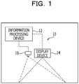
- the information processing system 10 includes an information processing device 12, a display device 14, and an imaging device 16.
- the information processing device 12 include information processing devices such as a personal computer or a server computer.
- the display device 14 performs display by projecting a screen on a display surface such as a wall of a conference room, a whiteboard, or an upper surface of a top plate of a desk, for example, under the control by the information processing device 12.
- Examples of the display device 14 include a projector. Although details will be described later, a plurality of objects to be operated by an operator are drawn and arranged over a screen displayed by the display device 14.
- the operator performs an operation of writing or the like an object such as a character or a figure on the object by using an electronic pen that emits infrared rays from a tip end portion, a finger of the operator, or the like.
- an electronic pen that emits infrared rays from a tip end portion, a finger of the operator, or the like.
- the operator brings the tip end portion of the electronic pen, the finger, or the like into contact with the screen.
- the operator performs an operation on the object in a state where the tip end portion of the electronic pen, the finger, or the like is in contact with the screen, and in a case of ending the operation, the operator releases the tip end portion of the electronic pen, the finger, or the like from the screen.
- the imaging device 16 includes an imaging unit capable of imaging infrared rays, and detects the operation by the operator on a plurality of objects arranged over the screen by imaging an imaging region including the screen displayed by the display device 14 at a predetermined frame rate.
- the imaging device 16 outputs a signal representing an image obtained by imaging to the information processing device 12. Examples of the imaging device 16 include a digital camera capable of imaging infrared rays.
- the imaging device 16 is an example of a detection device of the disclosed technique.
- a plurality of objects to be operated by the operator are drawn and arranged over the screen displayed by the display device 14. Over the screen, a plurality of operators may perform operations on different objects at substantially the same time. In this case, when a single operator continuously performs an operation on a plurality of different objects, it is preferable that the operation setting is taken over between the objects in order to smoothly progress the meeting.
- the information processing device 12 determines whether to take over the operation setting between the objects based on the continuity of the operation on the plurality of objects and a relationship between the plurality of objects.
- the information processing device 12 includes a detection unit 20, a determination unit 22, a setting unit 24, and a display control unit 26.
- An object information table 30 and an operation history table 32 are stored in a predetermined storage area of the information processing device 12.
- FIG. 4 illustrates an example of the object information table 30.
- the object information table 30 is a table in which information on objects arranged over the screen displayed by the display device 14 is stored.
- the object information table 30 stores, for each object, an ID, a type, a position, a size, and an angle as examples of the identification information of the object.
- the object information table 30 stores, for each object, the operation setting set for the object. Examples of the type of the object include a rectangular card such as an electronic sticky note, a note with ruled lines, an image, and an electronic simile paper.
- the position of the object according to the embodiment is represented by two-dimensional coordinates (for example, xy coordinates) of a predetermined position (center position in the embodiment) of the object with a predetermined position such as one of four corners or the center of the screen, as the origin.
- the size of the object according to the embodiment is represented by the longitudinal length and the lateral length of the object.
- the angle of the object according to the embodiment is represented by an angle of one side of the object with respect to one direction (for example, x-axis direction) over the screen.
- the operation setting in the object information table 30 includes the color and thickness of a line drawn on the screen by an operation on the object by the operator.
- the operation setting also includes a conversion mode for converting a handwritten character drawn by an operation on the object performed by the operator into a mechanical character, and the type and size of a font for the mechanical character.
- the operation setting includes information held in a clipboard for pasting when a paste operation is performed on the object.
- the operation setting may be stored in a table different from the object information table 30 in association with the IDs of the objects.
- the object is created, for example, when the operator performs an operation of drawing a predetermined figure (for example, a triangle) over the screen using an electronic pen, a finger, or the like, or an operation of selecting a specific menu, and information on the created object is stored in the object information table 30.
- the operation setting of the object may be set as predetermined initial setting or may be set by the operator who has created the object.
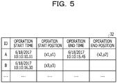
- FIG. 5 illustrates an example of the operation history table 32.
- the operation history table 32 is a table in which histories of operations performed on the object by each of a plurality of operators who perform operations on one screen are stored.
- the operation history table 32 stores an ID of an object, a time when an operator starts an operation on the object having the ID (hereinafter, referred to as "operation start time”), and a position where the operator starts the operation on the object having the ID (hereinafter, referred to as an "operation start position"). Further, the operation history table 32 stores a time when the operation on the object having the ID by the operator is ended (hereinafter, referred to as "operation end time”), and a position where the operation on the object having the ID by the operator is ended (hereinafter, referred to as an "operation end position").
- the operation start position and the operation end position are represented by two-dimensional coordinates with a predetermined position such as one of four corners or the center of the screen, as the origin.
- the detection unit 20 detects the operation start time and the operation start position based on a signal input from the imaging device 16.
- the detection unit 20 detects the operation end time and the operation end position based on a signal input from the imaging device 16.
- the detection unit 20 also detects a trajectory of the operation from the operation start position to the operation end position.
- the detection unit 20 specifies the object as the operation target based on the detected operation start position and the position and size of the object in the object information table 30. Then, the detection unit 20 stores the ID of the specified object in association with the detected operation start time, the detected operation start position, the detected operation end time, and the detected operation end position, in the operation history table 32.
- the detection unit 20 may store the operation at the operation start position within the same object as the previous one and the operation start time within the predetermined period from the previous operation end time, as one record in the operation history table 32 without detecting the operation as a new operation start.
- the determination unit 22 determines whether or not, before the object, there is an object that has been operated continuously with the object.
- the object from which the operation start is detected corresponds to a second object of the disclosed technique.
- a threshold TH1 for example, 1 second
- the determination unit 22 determines whether or not a distance d1 between the operation end position of the first object having the time interval t equal to or smaller than the threshold TH1 and the operation start position of the second object is equal to or smaller than a threshold TH2 (for example, 30 cm), by referring to the operation history table 32.
- the distance d1 is calculated according to the following Expression (1).
- x1 and y1 represent an x coordinate and a y coordinate of the operation end position of the first object
- x2 and y2 represent an x coordinate and a y coordinate of the operation start position of the second object.
- d 1 y 2 ⁇ y 1 2 + x 2 ⁇ x 1 2
- the determination unit 22 determines that the first object and the second object of which the time interval t is equal to or smaller than the threshold TH1 and the distance d1 is equal to or smaller than the threshold TH2 are continuously operated.
- the determination unit 22 may determine that the first object and the second object are continuously operated in a case where the time interval t is equal to or smaller than the threshold TH1 or in a case where the distance d1 is equal to or smaller than the threshold TH2.
- the threshold TH1 and the threshold TH2 may be proportional to each other. In this case, for example, the larger the value of the threshold TH1, the larger the value of the threshold TH2.
- the determination unit 22 determines whether or not the relationship between the first object and the second object that are determined to be continuously operated is within a range R predetermined as a close range, by referring to the object information table 30.
- the determination unit 22 determines whether or not the relationship is within the range R based on the positional relationship and the type of the first object and the second object.
- the determination unit 22 determines whether or not a distance d2 between corresponding positions (center positions in the embodiment) of the first object and the second object is equal to or smaller than a threshold TH3 (for example, 30 cm).
- the distance d2 is calculated according to the following Expression (2).
- x3 and y3 represent an x coordinate and a y coordinate of the center position of the first object
- x4 and y4 represent an x coordinate and a y coordinate of the center position of the second object.
- d 2 y 4 ⁇ y 3 2 + x 4 ⁇ x 3 2
- the determination unit 22 determines whether or not the absolute value (
- a threshold TH4 for example, 15°.
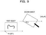
- FIG. 9 illustrates an example in which the angle of one side of the object (long side of the rectangular object in the example of FIG. 9 ) with respect to the x-axis direction (direction of the broken line arrow of FIG. 9 ) of the screen is applied as the angle of each object.
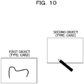
- the determination unit 22 determines whether or not the types of the first object and the second object are the same.
- the determination unit 22 determines that the relationship between the first object and the second object is within the range R.
- the determination unit 22 determines to take over the operation setting of the first object determined to be continuously operated and determined that the relationship is within the range R, to the second object.
- the determination unit 22 may determine that the relationship between the first object and the second object is within the range R when any one of or a combination of two of a case where the distance d2 is equal to or smaller than the threshold TH3, a case where the absolute value of the difference between the angles is equal to or smaller than the threshold TH4, and a case where the types are the same are satisfied.
- the determination unit 22 may determine to take over the operation setting of the first object determined to be continuously operated or the operation setting of the first object determined that the relationship is within the range R, to the second object.
- the setting unit 24 sets the operation setting of the first object as the operation setting of the second object. For example, in this case, the setting unit 24 overwrites the operation setting of the second object with the operation setting of the first object in the object information table 30. In this case, the setting unit 24 may save the operation setting of the second object before the overwriting of the operation setting, and may restore the operation setting of the second object in the object information table 30 after the operation on the second object is ended.
- the display control unit 26 performs control for displaying an object via the display device 14 according to the information stored in the object information table 30.
- the display control unit 26 performs control for displaying, via the display device 14, a result of the operation on the object performed by the operator which is detected by the detection unit 20, according to the operation setting of the corresponding object in the object information table 30.
- the display device 14 Under the control of the display control unit 26, the display device 14 performs display by projecting the result of the operation on the object performed by the operator, according to the operation setting of the object.
- the information processing device 12 may be achieved, for example, by a computer 40 illustrated in FIG. 11 .
- the computer 40 includes a central processing unit (CPU) 41, a memory 42 serving as a temporary storage area, and a non-volatile storage unit 43.
- the computer 40 includes an input/output device 44 such as a display device and an input device.
- the computer 40 also includes an external interface (I/F) 45 to which the display device 14 and the imaging device 16 are coupled.
- the computer 40 includes a read/write (R/W) unit 46 that controls reading and writing of data from and to a recording medium 49, and a network I/F 47 coupled to a network.
- the CPU 41, the memory 42, the storage unit 43, the input/output device 44, the external I/F 45, the R/W unit 46, and the network I/F 47 are coupled via a bus 48.
- the storage unit 43 may be achieved by a hard disk drive (HDD), a solid-state drive (SSD), a flash memory, or the like.
- the storage unit 43 as a storage medium stores an information processing program 50 for causing the computer 40 to function as the information processing device 12.
- the information processing program 50 has a detection process 51, a determination process 52, a setting process 53, and a display control process 54.
- the storage unit 43 has an information storage area 55 in which the object information table 30 and the operation history table 32 are stored.
- the CPU 41 reads the information processing program 50 from the storage unit 43 and loads the information processing program 50 into the memory 42 to execute the processes included in the information processing program 50.
- the CPU 41 operates as the detection unit 20 illustrated in FIG. 3 by executing the detection process 51.
- the CPU 41 operates as the determination unit 22 illustrated in FIG. 3 by executing the determination process 52.
- the CPU 41 operates as the setting unit 24 illustrated in FIG. 3 by executing the setting process 53.
- the CPU 41 operates as the display control unit 26 illustrated in FIG. 3 by executing the display control process 54.
- the computer 40 executing the information processing program 50 functions as the information processing device 12.
- the CPU 41 that executes the processes included in the information processing program 50 is hardware.
- the functions achieved by the information processing program 50 may be achieved by, for example, a semiconductor integrated circuit, more specifically, an application-specific integrated circuit (ASIC) or the like.
- ASIC application-specific integrated circuit
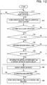
- the information processing device 12 executes the information processing program 50 to execute the setting takeover processing illustrated in FIG. 12 .
- the setting takeover processing illustrated in FIG. 12 is executed, for example, in a case where the information processing device 12 is powered on or in a case where an instruction to execute the information processing program 50 is input. It is assumed that the setting takeover processing is executed after the object is displayed over the screen.
- step S10 in FIG. 12 the detection unit 20 waits until the operation start time and the operation start position are detected based on the signal input from the imaging device 16.
- the determination in step S10 is affirmative, and the processing proceeds to step S12.
- step S12 the detection unit 20 specifies the object as the operation target based on the operation start position detected by the processing in step S10 and the position and size of the object in the object information table 30. Then, the detection unit 20 stores the ID of the specified object in association with the detected operation start time and the detected operation start position, in the operation history table 32.
- step S14 the determination unit 22 determines whether or not, before the second object from which the operation start is detected by the processing in step S10, there is the first object that has been continuously operated with the second object. In a case where the determination is negative, the processing proceeds to step S24, and in a case where the determination is affirmative, the processing proceeds to step S16.
- step S16 the determination unit 22 determines whether or not the distance d2 between the first object and the second object, which are determined to be continuously operated by the processing in step S14, is equal to or smaller than the threshold TH3. In a case where the determination is negative, the processing proceeds to step S24, and in a case where the determination is affirmative, the processing proceeds to step S18.
- step S18 the determination unit 22 determines whether or not the absolute value of the difference between the angles of the first object and the second object, which are determined to be continuously operated by the processing in step S14, is equal to or smaller than the threshold TH4. In a case where the determination is negative, the processing proceeds to step S24, and in a case where the determination is affirmative, the processing proceeds to step S20.
- step S20 the determination unit 22 determines whether or not the types of the first object and the second object, which are determined to be continuously operated by the processing in step S14, are the same. In a case where the determination is negative, the processing proceeds to step S24, and in a case where the determination is affirmative, the processing proceeds to step S22.
- step S22 as described above, the setting unit 24 sets the operation setting of the first object as the operation setting of the second object.
- the display control unit 26 performs, by referring to the object information table 30, control for displaying the operation result according to the trajectory of the operation on the object performed by the operator, according to the operation setting of the object from which the operation start is detected by the processing in step S10.
- step S26 the detection unit 20 determines whether or not the operation end time and the operation end position are detected based on the signal input from the imaging device 16. In a case where the determination is negative, the processing returns to step S24, and in a case where the determination is affirmative, the processing proceeds to step S28.
- step S28 the detection unit 20 stores the operation end time and the operation end position detected by the processing in step S26 in association with the ID of the object specified by the processing in step S12, in the operation history table 32.
- the processing in step S28 is ended, the processing returns to step S10.
- the setting takeover processing illustrated in FIG. 12 is ended, for example, in a case where the information processing device 12 is powered off or in a case where an instruction to end the information processing program 50 is input.
- the operation setting of the first object is set as the operation setting of the second object. Therefore, the operation setting may be taken over between the objects without using equipment for specifying the operator.
- the time interval t is equal to or smaller than the threshold TH1 and the distance d1 is equal to or smaller than the threshold TH2
- the distance d2 is equal to or smaller than the threshold TH3
- the absolute value of the difference between the angles is equal to or smaller than the threshold TH4
- the types of the objects are the same
- it is determined that the relationship between the first object and the second object is within the range R. Therefore, it is possible to accurately determine whether or not the first object and the second object are operated by the same operator.
- a second embodiment of the disclosed technique will be described.
- the configuration of the information processing system 10 according to the embodiment is the same as that of the first embodiment, and therefore description thereof is omitted.
- examples of such a situation include a case where an operator A performs an operation on an object A, an operator B performs an operation on an object C, and those operations are ended at substantially the same time.
- the operator A starts an operation on an object B immediately after the end of the operation on the object A, it is determined that the object A and the object B are continuously operated and the object C and the object B are continuously operated.
- the relationship between the object A and the object B is within the range R
- the relationship between the object B and the object C is within the range R.
- the first object determined as the takeover source of which the operation setting is taken over by the object B as the second object is two of the object A and the object C.
- an information processing device 12A has a function of deciding which of the object A and the object C the operation setting of the object is to be taken over by the object B.
- the number of first objects is not limited to two, and may be three or more.
- the information processing device 12A includes the detection unit 20, the determination unit 22, a setting unit 24A, a display control unit 26A, and an acceptance unit 28.
- the display control unit 26A has the following functions in addition to the functions of the display control unit 26 according to the first embodiment. In a case where there are a plurality of first objects determined by the determination unit 22 that the operation setting thereof is taken over by the second object, the display control unit 26A performs control for displaying the operation setting of each of the plurality of first objects, by referring to the object information table 30. For example, as illustrated in FIG. 15 , the display control unit 26A performs control for displaying, on the second object, information representing the operation setting of each of the plurality of first objects.
- FIG. 15 illustrates an example of a case where the object A and the object C are the first objects and the object B is the second object.
- FIG. 15 illustrates an example of a case where the color included in the operation setting of the object A is red and the color included in the operation setting of the object C is blue.
- the operator selects the operation setting to be used by the operator from the displayed operation setting of each of the plurality of first objects. For example, in FIG. 15 , the operator A selects "red".
- the acceptance unit 28 accepts the operation setting selected by the operator.
- the setting unit 24A has the following functions in addition to the functions of the setting unit 24 according to the first embodiment.
- the setting unit 24A sets the operation setting accepted by the acceptance unit 28 as the operation setting of the second object.
- the information processing device 12A may be achieved, for example, by the computer 40 illustrated in FIG. 16 .
- the storage unit 43 of the computer 40 stores an information processing program 50A for causing the computer 40 to function as the information processing device 12A.
- the information processing program 50A has the detection process 51, the determination process 52, a setting process 53A, a display control process 54A, and an acceptance process 56.
- the CPU 41 reads the information processing program 50A from the storage unit 43 and loads the information processing program 50A into the memory 42 to execute the processes included in the information processing program 50A.
- the CPU 41 operates as the detection unit 20 illustrated in FIG. 14 by executing the detection process 51.
- the CPU 41 operates as the determination unit 22 illustrated in FIG. 14 by executing the determination process 52.
- the CPU 41 operates as the setting unit 24A illustrated in FIG. 14 by executing the setting process 53A.
- the CPU 41 operates as the display control unit 26A illustrated in FIG. 14 by executing the display control process 54A.
- the CPU 41 operates as the acceptance unit 28 illustrated in FIG. 14 by executing the acceptance process 56.
- the computer 40 executing the information processing program 50A functions as the information processing device 12A.
- the CPU 41 that executes the processes included in the information processing program 50A is hardware.
- the functions achieved by the information processing program 50A may be achieved by, for example, a semiconductor integrated circuit, more specifically, an ASIC or the like.
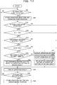
- the information processing device 12A executes the information processing program 50A to execute the setting takeover processing illustrated in FIG. 17 .
- the setting takeover processing illustrated in FIG. 17 is executed, for example, in a case where the information processing device 12A is powered on or in a case where an instruction to execute the information processing program 50A is input. It is assumed that the setting takeover processing is executed after the object is displayed over the screen.
- the steps executing the same processing as in FIG. 12 are denoted by the same reference numerals, and the description thereof is omitted.
- step S30 the display control unit 26A determines whether or not there are a plurality of first objects which are determined to be continuously operated with the second object, to have the distance d2 equal to or smaller than the threshold TH3, to have the absolute value of the difference between the angles equal to or smaller than the threshold TH4, and to be the same type as the second object.
- the processing proceeds to step S32, and in a case where the determination is affirmative, the processing proceeds to step S22.
- step S32 the display control unit 26A performs control for displaying the operation setting of each of the plurality of first objects by referring to the object information table 30.
- the operator selects the operation setting to be used by the operator from the operation setting of each of the plurality of first objects displayed by the processing of step S32.
- step S34 the acceptance unit 28 accepts the operation setting selected by the operator.
- step S36 the setting unit 24A sets the operation setting accepted by the processing of step S34 as the operation setting of the second object.
- the processing proceeds to step S24.
- the same effects as those in the first embodiment may be obtained.
- the operation setting of each of the plurality of first objects are displayed, the operation setting selected by the operator are accepted, and the accepted operation setting is set as the operation setting of the second object. Therefore, even in a case where there are a plurality of first objects, an appropriate operation setting may be set for the second object.
- the setting unit 24A may set an operation setting between (for example, intermediate) the operation settings of the plurality of first objects as the operation setting of the second object.
- FIG. 18 illustrates an example of a case where the object A and the object C are the first objects and the object B is the second object.
- FIG. 18 illustrates an example of a case where the color included in the operation setting of the object A is red and the color included in the operation setting of the object C is blue.
- FIG. 18 illustrates an example in which the setting unit 24 sets purple, which is an intermediate color between red and blue, as the operation setting of the object B.
- the setting unit 24 may set the operation setting of the first object having the shortest distance d1 or d2 among the plurality of first objects, as the operation setting of the second object.
- the setting unit 24 may set the operation setting of the first object having the shortest time interval t among the plurality of first objects, as the operation setting of the second object.
- a third embodiment of the disclosed technique will be described.
- the configuration of the information processing system 10 according to the embodiment is the same as that of the first embodiment, and therefore description thereof is omitted.
- a form example in which the range R is displayed in an identifiable manner during the operation on the first object will be described.
- the information processing device 12B includes the detection unit 20, the determination unit 22, the setting unit 24, and a display control unit 26B.
- the display control unit 26B has the following functions in addition to the functions of the display control unit 26 according to the first embodiment.
- the display control unit 26B performs control for displaying the range R corresponding to the first object in an identifiable manner during the operation on the first object. For example, as illustrated in FIG. 19 as an example, the display control unit 26B performs control for displaying, in a shaded manner, a region (193, 194) where the distance from the center position of the first object (191, 192) being operated is within the range of the threshold TH3.
- the display control unit 26B may specify, with respect to the first object being operated, a second object which has the distance d2 equal to or smaller than the threshold TH3, has the absolute value of the difference between the angles equal to or smaller than the threshold TH4, and is the same type.
- a form in which the display control unit 26B displays the specified second object in a color different from that of the first object a form in which the display control unit 26B displays the specified second object in a blinking manner, and the like are exemplified.
- the information processing device 12B may be achieved, for example, by the computer 40 illustrated in FIG. 11 .
- the storage unit 43 of the computer 40 stores an information processing program 50B for causing the computer 40 to function as the information processing device 12B.
- the information processing program 50B has the detection process 51, the determination process 52, the setting process 53, and a display control process 54B.
- the CPU 41 reads the information processing program 50B from the storage unit 43 and loads the information processing program 50B into the memory 42 to execute the processes included in the information processing program 50B.
- the CPU 41 operates as the detection unit 20 illustrated in FIG. 3 by executing the detection process 51.
- the CPU 41 operates as the determination unit 22 illustrated in FIG. 3 by executing the determination process 52.
- the CPU 41 operates as the setting unit 24 illustrated in FIG. 3 by executing the setting process 53.
- the CPU 41 operates as the display control unit 26B illustrated in FIG. 3 by executing the display control process 54B.
- the computer 40 executing the information processing program 50B functions as the information processing device 12B.
- the CPU 41 that executes the processes included in the information processing program 50B is hardware.
- the functions achieved by the information processing program 50B may be achieved by, for example, a semiconductor integrated circuit, more specifically, an ASIC or the like.
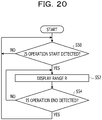
- the information processing device 12B executes the information processing program 50B to execute the range display processing illustrated in FIG. 20 .
- the range display processing illustrated in FIG. 20 is executed, for example, in a case where the information processing device 12B is powered on or in a case where an instruction to execute the information processing program 50B is input. It is assumed that the range display processing is executed after the object is displayed over the screen.
- the setting takeover processing according to the embodiment is the same as the setting takeover processing according to the first embodiment illustrated in FIG. 12 , and therefore the description thereof is omitted.
- step S50 in FIG. 20 the detection unit 20 waits until the operation start time and the operation start position are detected based on the signal input from the imaging device 16.
- the determination in step S50 is affirmative, and the processing proceeds to step S52.
- step S52 the display control unit 26B performs control for displaying, in an identifiable manner, the range R corresponding to the first object of which the operation start is detected by the processing in step S50.
- step S54 the detection unit 20 determines whether or not the operation end time and the operation end position are detected based on the signal input from the imaging device 16. In a case where the determination is negative, the processing returns to step S52, and in a case where the determination is affirmative, the processing returns to step S50.
- the range display processing illustrated in FIG. 20 is ended, for example, in a case where the information processing device 12B is powered off or in a case where an instruction to end the information processing program 50B is input.
- the range R is displayed in an identifiable manner during the operation on the first object. Therefore, during the operation on the first object, the operator may recognize the second object to which the operation setting of the first object is taken over.
- the display surface is a surface along the horizontal direction such as the upper surface of the top plate of the desk
- the absolute value of the difference between the angles is used for determining whether or not the relationship is within the range R.
- FIG. 21 as an example, in a case where the operators A and B at the positions facing the adjacent sides of the display surface operate the objects in the directions facing the operators A and B themselves, it is possible to suppress that the operation setting is taken over between the objects.
- the threshold TH3 may be set to a larger value as the operation time for the first object is longer.
- the upper limit value of the threshold TH3 may be determined according to the restriction such as the movement of the body of the operator (for example, reachable range by the hand).
- the threshold TH3 may be set to a larger value as the angle of the screen with respect to the vertical direction is smaller.
- the movable range of the operator is often larger than in a case where the screen is displayed on a surface along the horizontal direction such as the upper surface of the top plate of the desk. Therefore, a form is exemplified in which, in a case where the screen is along the vertical direction, the threshold TH3 is set to be larger than in a case where the screen is along the horizontal direction.
- the display device 14 may be a touch panel display in which a touch panel and a display unit are integrated.
- the information processing system 10 may not include the imaging device 16.
- the touch panel of the touch panel display corresponds to the detection device of the disclosed technique
- the display unit of the touch panel display corresponds to the display device of the disclosed technique.
- the information processing program 50, 50A, or 50B may be provided in a form of being recorded in a recording medium such as a compact disc read-only memory (CD-ROM), a Digital Versatile Disc (DVD)-ROM, a Universal Serial Bus (USB) memory, or a memory card.
- a recording medium such as a compact disc read-only memory (CD-ROM), a Digital Versatile Disc (DVD)-ROM, a Universal Serial Bus (USB) memory, or a memory card.
Landscapes
- Engineering & Computer Science (AREA)
- General Engineering & Computer Science (AREA)
- Theoretical Computer Science (AREA)
- Human Computer Interaction (AREA)
- Physics & Mathematics (AREA)
- General Physics & Mathematics (AREA)
- User Interface Of Digital Computer (AREA)
- Position Input By Displaying (AREA)
Abstract
Description
- The embodiments discussed herein are related to an information processing apparatus, an information processing program, and an information processing system.
- In the related art, a technique for converting a graphical user interface (GUI) of an installed application between pieces of information equipment having different types and specifications of input devices and output devices has been disclosed. In this technique, an evaluation scale of the operability of the GUI is calculated according to a time for completing an operation task for an object included in a GUI area. Japanese Laid-open Patent Publication No.
2015-49661 - In a meeting using information equipment where multiple people participate, there is a case where an operator performs an operation of writing a character, a figure, or the like to an object such as an electronic sticky note arranged over a screen. For example, in a case where a plurality of objects are arranged over a relatively large screen, a plurality of operators may perform operations on different objects at substantially the same timing.
- In a case where the operator performs an operation on an object, for example, operation settings such as the color and thickness of a line to be written to the object are applied. It is preferable that the operation setting is set for each operator in order to, for example, identify the operator who has performed an operation on an object and reflect the operator's preference. For example, in a case where the same operator performs operations on a plurality of different objects, it is preferable that the operation setting is taken over between the objects.
- According to an aspect of the embodiments, an information processing apparatus includes: a memory, and a processor coupled to the memory and configured to: determine, among a plurality of objects which are arranged over a screen and are operable by a plurality of operators, whether a first object and a second object operated after the first object are continuously operated, or whether a relationship between the first object and the second object is within a predetermined range as a close range; and set an operation setting of the first object as an operation setting of the second object in a case where the operations are performed continuously, or in a case where the relationship is within the predetermined range.
-
-
FIG. 1 is a block diagram illustrating a schematic configuration of an information processing system according to each embodiment; -
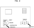
FIG. 2 is a diagram for describing takeover of an operation setting of an object according to each embodiment; -
FIG. 3 is a functional block diagram of an information processing device according to first and third embodiments; -
FIG. 4 is a diagram illustrating an example of an object information table according to each embodiment; -
FIG. 5 is a diagram illustrating an example of an operation history table according to each embodiment; -
FIG. 6 is a diagram for describing a time interval between an end of an operation on a first object and a start of an operation on a second object; -
FIG. 7 is a diagram for describing a distance between a position at which an operation on the first object is ended and a position at which an operation on the second object is started; -
FIG. 8 is a diagram for describing a distance between the first object and the second object; -
FIG. 9 is a diagram for describing a difference in angle between the first object and the second object; -
FIG. 10 is a diagram for describing types of the first object and the second object; -
FIG. 11 is a block diagram illustrating a schematic configuration of a computer that functions as the information processing device according to the first and third embodiments; -
FIG. 12 is a flowchart illustrating an example of setting takeover processing according to the first and third embodiments; -
FIG. 13 is a diagram for describing an example in which there are a plurality of first objects; -
FIG. 14 is a functional block diagram of an information processing device according to a second embodiment; -
FIG. 15 is a diagram for describing processing of displaying the operation setting of each of the first objects; -
FIG. 16 is a block diagram illustrating a schematic configuration of a computer that functions as the information processing device according to the second embodiment; -
FIG. 17 is a flowchart illustrating an example of setting takeover processing according to the second embodiment; -
FIG. 18 is a diagram for describing a modification example in a case where there are a plurality of first objects; -
FIG. 19 is a diagram for describing processing of displaying a range in which a relationship corresponding to the first objects being operated is close; -
FIG. 20 is a flowchart illustrating an example of range display processing according to the third embodiment; and -
FIG. 21 is a diagram for describing an effect of using the difference in angle between the first object and the second object. - In a case where the operation setting is set for each operator, for example, it is considered that the operator is specified by identification information on the equipment used when an operation is performed on an object such as an electronic pen, or by face detection processing on an image of the operator captured by photographing equipment, and the operation setting is set for each specified operator. However, in this case, since the equipment for specifying the operator is used, and processing for specifying the operator is also performed, there is a problem that the configuration and processing of the system for taking over the operation setting are complicated. In the technique for converting the GUI described above, taking over the operation setting between objects is not considered in the first place.
- As one aspect, an object of the disclosed technique is to take over (or take on) an operation setting between objects without using equipment for specifying an operator.
- Hereinafter, examples of an embodiment of the disclosed technique will be described in detail with reference to the accompanying drawings.
- With reference to
FIG. 1 , a configuration of aninformation processing system 10 according to the embodiment will be described. As illustrated inFIG. 1 , theinformation processing system 10 includes aninformation processing device 12, adisplay device 14, and animaging device 16. Examples of theinformation processing device 12 include information processing devices such as a personal computer or a server computer. - The
display device 14 performs display by projecting a screen on a display surface such as a wall of a conference room, a whiteboard, or an upper surface of a top plate of a desk, for example, under the control by theinformation processing device 12. Examples of thedisplay device 14 include a projector. Although details will be described later, a plurality of objects to be operated by an operator are drawn and arranged over a screen displayed by thedisplay device 14. - In the embodiment, the operator performs an operation of writing or the like an object such as a character or a figure on the object by using an electronic pen that emits infrared rays from a tip end portion, a finger of the operator, or the like. For example, in a case of starting an operation on the object, the operator brings the tip end portion of the electronic pen, the finger, or the like into contact with the screen. The operator performs an operation on the object in a state where the tip end portion of the electronic pen, the finger, or the like is in contact with the screen, and in a case of ending the operation, the operator releases the tip end portion of the electronic pen, the finger, or the like from the screen.
- The
imaging device 16 includes an imaging unit capable of imaging infrared rays, and detects the operation by the operator on a plurality of objects arranged over the screen by imaging an imaging region including the screen displayed by thedisplay device 14 at a predetermined frame rate. Theimaging device 16 outputs a signal representing an image obtained by imaging to theinformation processing device 12. Examples of theimaging device 16 include a digital camera capable of imaging infrared rays. Theimaging device 16 is an example of a detection device of the disclosed technique. - As illustrated in
FIG. 2 as an example, a plurality of objects to be operated by the operator are drawn and arranged over the screen displayed by thedisplay device 14. Over the screen, a plurality of operators may perform operations on different objects at substantially the same time. In this case, when a single operator continuously performs an operation on a plurality of different objects, it is preferable that the operation setting is taken over between the objects in order to smoothly progress the meeting. - The
information processing device 12 according to the embodiment determines whether to take over the operation setting between the objects based on the continuity of the operation on the plurality of objects and a relationship between the plurality of objects. - Next, with reference to
FIG. 3 , a functional configuration of theinformation processing device 12 according to the embodiment will be described. As illustrated inFIG. 3 , theinformation processing device 12 includes adetection unit 20, adetermination unit 22, asetting unit 24, and adisplay control unit 26. An object information table 30 and an operation history table 32 are stored in a predetermined storage area of theinformation processing device 12. -
FIG. 4 illustrates an example of the object information table 30. The object information table 30 is a table in which information on objects arranged over the screen displayed by thedisplay device 14 is stored. - As illustrated in
FIG. 4 , the object information table 30 stores, for each object, an ID, a type, a position, a size, and an angle as examples of the identification information of the object. The object information table 30 stores, for each object, the operation setting set for the object. Examples of the type of the object include a rectangular card such as an electronic sticky note, a note with ruled lines, an image, and an electronic simile paper. - The position of the object according to the embodiment is represented by two-dimensional coordinates (for example, xy coordinates) of a predetermined position (center position in the embodiment) of the object with a predetermined position such as one of four corners or the center of the screen, as the origin. The size of the object according to the embodiment is represented by the longitudinal length and the lateral length of the object. The angle of the object according to the embodiment is represented by an angle of one side of the object with respect to one direction (for example, x-axis direction) over the screen.
- The operation setting in the object information table 30 includes the color and thickness of a line drawn on the screen by an operation on the object by the operator. The operation setting also includes a conversion mode for converting a handwritten character drawn by an operation on the object performed by the operator into a mechanical character, and the type and size of a font for the mechanical character. The operation setting includes information held in a clipboard for pasting when a paste operation is performed on the object. The operation setting may be stored in a table different from the object information table 30 in association with the IDs of the objects.
- The object is created, for example, when the operator performs an operation of drawing a predetermined figure (for example, a triangle) over the screen using an electronic pen, a finger, or the like, or an operation of selecting a specific menu, and information on the created object is stored in the object information table 30. In this case, the operation setting of the object may be set as predetermined initial setting or may be set by the operator who has created the object.
-
FIG. 5 illustrates an example of the operation history table 32. The operation history table 32 is a table in which histories of operations performed on the object by each of a plurality of operators who perform operations on one screen are stored. - As illustrated in
FIG. 5 , the operation history table 32 stores an ID of an object, a time when an operator starts an operation on the object having the ID (hereinafter, referred to as "operation start time"), and a position where the operator starts the operation on the object having the ID (hereinafter, referred to as an "operation start position"). Further, the operation history table 32 stores a time when the operation on the object having the ID by the operator is ended (hereinafter, referred to as "operation end time"), and a position where the operation on the object having the ID by the operator is ended (hereinafter, referred to as an "operation end position"). - Similar to the position of the object described above, the operation start position and the operation end position according to the embodiment are represented by two-dimensional coordinates with a predetermined position such as one of four corners or the center of the screen, as the origin.
- The
detection unit 20 detects the operation start time and the operation start position based on a signal input from theimaging device 16. Thedetection unit 20 detects the operation end time and the operation end position based on a signal input from theimaging device 16. Thedetection unit 20 also detects a trajectory of the operation from the operation start position to the operation end position. - The
detection unit 20 specifies the object as the operation target based on the detected operation start position and the position and size of the object in the object information table 30. Then, thedetection unit 20 stores the ID of the specified object in association with the detected operation start time, the detected operation start position, the detected operation end time, and the detected operation end position, in the operation history table 32. - In a case where the operation start position is within the same object as the previous one and the operation start time is within a predetermined period (for example, 1 second) from the previous operation end time, the
detection unit 20 may store the operation at the operation start position within the same object as the previous one and the operation start time within the predetermined period from the previous operation end time, as one record in the operation history table 32 without detecting the operation as a new operation start. - In a case where the start of the operation on an object is detected by the
detection unit 20, thedetermination unit 22 determines whether or not, before the object, there is an object that has been operated continuously with the object. The object from which the operation start is detected corresponds to a second object of the disclosed technique. - For example, as illustrated in
FIG. 6 , thedetermination unit 22 performs the following determination for an object of which the operation end time t1 is earlier than the operation start time t2 of an object from which the operation start is detected, by referring to the operation history table 32. For example, in this case, thedetermination unit 22 determines whether or not there is an object for which a time interval t (t = t2-t1) between the operation start time t2 and the operation end time t1 is equal to or smaller than a threshold TH1 (for example, 1 second), by referring to the operation history table 32. The object of which the operation end time t1 is earlier than the operation start time t2 of the object from which the operation start is detected corresponds to a first object of the disclosed technique. - As illustrated in
FIG. 7 , thedetermination unit 22 determines whether or not a distance d1 between the operation end position of the first object having the time interval t equal to or smaller than the threshold TH1 and the operation start position of the second object is equal to or smaller than a threshold TH2 (for example, 30 cm), by referring to the operation history table 32. The distance d1 is calculated according to the following Expression (1). In Expression (1), x1 and y1 represent an x coordinate and a y coordinate of the operation end position of the first object, and x2 and y2 represent an x coordinate and a y coordinate of the operation start position of the second object.
- The
determination unit 22 determines that the first object and the second object of which the time interval t is equal to or smaller than the threshold TH1 and the distance d1 is equal to or smaller than the threshold TH2 are continuously operated. Thedetermination unit 22 may determine that the first object and the second object are continuously operated in a case where the time interval t is equal to or smaller than the threshold TH1 or in a case where the distance d1 is equal to or smaller than the threshold TH2. The threshold TH1 and the threshold TH2 may be proportional to each other. In this case, for example, the larger the value of the threshold TH1, the larger the value of the threshold TH2. - The
determination unit 22 determines whether or not the relationship between the first object and the second object that are determined to be continuously operated is within a range R predetermined as a close range, by referring to the object information table 30. Thedetermination unit 22 according to the embodiment determines whether or not the relationship is within the range R based on the positional relationship and the type of the first object and the second object. - Specifically, as illustrated in
FIG. 8 , thedetermination unit 22 determines whether or not a distance d2 between corresponding positions (center positions in the embodiment) of the first object and the second object is equal to or smaller than a threshold TH3 (for example, 30 cm). The distance d2 is calculated according to the following Expression (2). In Expression (2), x3 and y3 represent an x coordinate and a y coordinate of the center position of the first object, and x4 and y4 represent an x coordinate and a y coordinate of the center position of the second object.
- As illustrated in
FIG. 9 , thedetermination unit 22 determines whether or not the absolute value (|θ2-θ1|) of the difference between the angles of the first object and the second object is equal to or smaller than a threshold TH4 (for example, 15°).FIG. 9 illustrates an example in which the angle of one side of the object (long side of the rectangular object in the example ofFIG. 9 ) with respect to the x-axis direction (direction of the broken line arrow ofFIG. 9 ) of the screen is applied as the angle of each object. - As illustrated in
FIG. 10 , thedetermination unit 22 determines whether or not the types of the first object and the second object are the same. - In a case where the distance d2 between of the first object and the second object is equal to or smaller than the threshold TH3, the absolute value of the difference between the angles of the first object and the second object is equal to or smaller than the threshold TH4, and the types of the first object and the second object are the same, the
determination unit 22 determines that the relationship between the first object and the second object is within the range R. Thedetermination unit 22 determines to take over the operation setting of the first object determined to be continuously operated and determined that the relationship is within the range R, to the second object. Thedetermination unit 22 may determine that the relationship between the first object and the second object is within the range R when any one of or a combination of two of a case where the distance d2 is equal to or smaller than the threshold TH3, a case where the absolute value of the difference between the angles is equal to or smaller than the threshold TH4, and a case where the types are the same are satisfied. Thedetermination unit 22 may determine to take over the operation setting of the first object determined to be continuously operated or the operation setting of the first object determined that the relationship is within the range R, to the second object. - In a case where the
determination unit 22 determines to take over the operation setting of the first object to the second object, the settingunit 24 sets the operation setting of the first object as the operation setting of the second object. For example, in this case, the settingunit 24 overwrites the operation setting of the second object with the operation setting of the first object in the object information table 30. In this case, the settingunit 24 may save the operation setting of the second object before the overwriting of the operation setting, and may restore the operation setting of the second object in the object information table 30 after the operation on the second object is ended. - The
display control unit 26 performs control for displaying an object via thedisplay device 14 according to the information stored in the object information table 30. Thedisplay control unit 26 performs control for displaying, via thedisplay device 14, a result of the operation on the object performed by the operator which is detected by thedetection unit 20, according to the operation setting of the corresponding object in the object information table 30. Under the control of thedisplay control unit 26, thedisplay device 14 performs display by projecting the result of the operation on the object performed by the operator, according to the operation setting of the object. - The
information processing device 12 may be achieved, for example, by acomputer 40 illustrated inFIG. 11 . Thecomputer 40 includes a central processing unit (CPU) 41, amemory 42 serving as a temporary storage area, and anon-volatile storage unit 43. Thecomputer 40 includes an input/output device 44 such as a display device and an input device. Thecomputer 40 also includes an external interface (I/F) 45 to which thedisplay device 14 and theimaging device 16 are coupled. Thecomputer 40 includes a read/write (R/W)unit 46 that controls reading and writing of data from and to arecording medium 49, and a network I/F 47 coupled to a network. TheCPU 41, thememory 42, thestorage unit 43, the input/output device 44, the external I/F 45, the R/W unit 46, and the network I/F 47 are coupled via abus 48. - The
storage unit 43 may be achieved by a hard disk drive (HDD), a solid-state drive (SSD), a flash memory, or the like. Thestorage unit 43 as a storage medium stores aninformation processing program 50 for causing thecomputer 40 to function as theinformation processing device 12. Theinformation processing program 50 has adetection process 51, adetermination process 52, asetting process 53, and adisplay control process 54. Thestorage unit 43 has aninformation storage area 55 in which the object information table 30 and the operation history table 32 are stored. - The
CPU 41 reads theinformation processing program 50 from thestorage unit 43 and loads theinformation processing program 50 into thememory 42 to execute the processes included in theinformation processing program 50. TheCPU 41 operates as thedetection unit 20 illustrated inFIG. 3 by executing thedetection process 51. TheCPU 41 operates as thedetermination unit 22 illustrated inFIG. 3 by executing thedetermination process 52. TheCPU 41 operates as the settingunit 24 illustrated inFIG. 3 by executing thesetting process 53. TheCPU 41 operates as thedisplay control unit 26 illustrated inFIG. 3 by executing thedisplay control process 54. Thus, thecomputer 40 executing theinformation processing program 50 functions as theinformation processing device 12. TheCPU 41 that executes the processes included in theinformation processing program 50 is hardware. - The functions achieved by the
information processing program 50 may be achieved by, for example, a semiconductor integrated circuit, more specifically, an application-specific integrated circuit (ASIC) or the like. - Next, the operation of the
information processing device 12 according to the embodiment will be described. Theinformation processing device 12 executes theinformation processing program 50 to execute the setting takeover processing illustrated inFIG. 12 . The setting takeover processing illustrated inFIG. 12 is executed, for example, in a case where theinformation processing device 12 is powered on or in a case where an instruction to execute theinformation processing program 50 is input. It is assumed that the setting takeover processing is executed after the object is displayed over the screen. - In step S10 in
FIG. 12 , thedetection unit 20 waits until the operation start time and the operation start position are detected based on the signal input from theimaging device 16. When thedetection unit 20 detects the operation start time and the operation start position, the determination in step S10 is affirmative, and the processing proceeds to step S12. - In step S12, the
detection unit 20 specifies the object as the operation target based on the operation start position detected by the processing in step S10 and the position and size of the object in the object information table 30. Then, thedetection unit 20 stores the ID of the specified object in association with the detected operation start time and the detected operation start position, in the operation history table 32. - In step S14, as described above, the
determination unit 22 determines whether or not, before the second object from which the operation start is detected by the processing in step S10, there is the first object that has been continuously operated with the second object. In a case where the determination is negative, the processing proceeds to step S24, and in a case where the determination is affirmative, the processing proceeds to step S16. - In step S16, as described above, the
determination unit 22 determines whether or not the distance d2 between the first object and the second object, which are determined to be continuously operated by the processing in step S14, is equal to or smaller than the threshold TH3. In a case where the determination is negative, the processing proceeds to step S24, and in a case where the determination is affirmative, the processing proceeds to step S18. - In step S18, as described above, the
determination unit 22 determines whether or not the absolute value of the difference between the angles of the first object and the second object, which are determined to be continuously operated by the processing in step S14, is equal to or smaller than the threshold TH4. In a case where the determination is negative, the processing proceeds to step S24, and in a case where the determination is affirmative, the processing proceeds to step S20. - In step S20, as described above, the
determination unit 22 determines whether or not the types of the first object and the second object, which are determined to be continuously operated by the processing in step S14, are the same. In a case where the determination is negative, the processing proceeds to step S24, and in a case where the determination is affirmative, the processing proceeds to step S22. - In step S22, as described above, the setting
unit 24 sets the operation setting of the first object as the operation setting of the second object. In step S24, thedisplay control unit 26 performs, by referring to the object information table 30, control for displaying the operation result according to the trajectory of the operation on the object performed by the operator, according to the operation setting of the object from which the operation start is detected by the processing in step S10. - In step S26, the
detection unit 20 determines whether or not the operation end time and the operation end position are detected based on the signal input from theimaging device 16. In a case where the determination is negative, the processing returns to step S24, and in a case where the determination is affirmative, the processing proceeds to step S28. - In step S28, the
detection unit 20 stores the operation end time and the operation end position detected by the processing in step S26 in association with the ID of the object specified by the processing in step S12, in the operation history table 32. When the processing in step S28 is ended, the processing returns to step S10. The setting takeover processing illustrated inFIG. 12 is ended, for example, in a case where theinformation processing device 12 is powered off or in a case where an instruction to end theinformation processing program 50 is input. - As described above, according to the embodiment, in a case where the first object and the second object are continuously operated and the relationship therebetween is within the range R, the operation setting of the first object is set as the operation setting of the second object. Therefore, the operation setting may be taken over between the objects without using equipment for specifying the operator.
- According to the embodiment, in a case where the time interval t is equal to or smaller than the threshold TH1 and the distance d1 is equal to or smaller than the threshold TH2, it is determined that the first object and the second object are continuously operated. According to the embodiment, in a case where the distance d2 is equal to or smaller than the threshold TH3, the absolute value of the difference between the angles is equal to or smaller than the threshold TH4, and the types of the objects are the same, it is determined that the relationship between the first object and the second object is within the range R. Therefore, it is possible to accurately determine whether or not the first object and the second object are operated by the same operator.
- A second embodiment of the disclosed technique will be described. The configuration of the
information processing system 10 according to the embodiment is the same as that of the first embodiment, and therefore description thereof is omitted. - In the embodiment, a form example of a case where there are a plurality of first objects as the takeover source, of which the operation setting is taken over by the second object will be described. As illustrated in
FIG. 13 , examples of such a situation include a case where an operator A performs an operation on an object A, an operator B performs an operation on an object C, and those operations are ended at substantially the same time. In this case, for example, when the operator A starts an operation on an object B immediately after the end of the operation on the object A, it is determined that the object A and the object B are continuously operated and the object C and the object B are continuously operated. It is further assumed that the relationship between the object A and the object B is within the range R, and the relationship between the object B and the object C is within the range R. - In this case, the first object determined as the takeover source of which the operation setting is taken over by the object B as the second object, is two of the object A and the object C. In such a case, an
information processing device 12A according to the embodiment has a function of deciding which of the object A and the object C the operation setting of the object is to be taken over by the object B. The number of first objects is not limited to two, and may be three or more. - With reference to
FIG. 14 , a functional configuration of theinformation processing device 12A according to the embodiment will be described. The functional units having the same functions as the functional units of theinformation processing device 12 according to the first embodiment are denoted by the same reference numerals and description thereof is omitted. As illustrated inFIG. 14 , theinformation processing device 12A includes thedetection unit 20, thedetermination unit 22, asetting unit 24A, adisplay control unit 26A, and anacceptance unit 28. - The
display control unit 26A has the following functions in addition to the functions of thedisplay control unit 26 according to the first embodiment. In a case where there are a plurality of first objects determined by thedetermination unit 22 that the operation setting thereof is taken over by the second object, thedisplay control unit 26A performs control for displaying the operation setting of each of the plurality of first objects, by referring to the object information table 30. For example, as illustrated inFIG. 15 , thedisplay control unit 26A performs control for displaying, on the second object, information representing the operation setting of each of the plurality of first objects. -
FIG. 15 illustrates an example of a case where the object A and the object C are the first objects and the object B is the second object.FIG. 15 illustrates an example of a case where the color included in the operation setting of the object A is red and the color included in the operation setting of the object C is blue. - The operator selects the operation setting to be used by the operator from the displayed operation setting of each of the plurality of first objects. For example, in
FIG. 15 , the operator A selects "red". Theacceptance unit 28 accepts the operation setting selected by the operator. - The
setting unit 24A has the following functions in addition to the functions of thesetting unit 24 according to the first embodiment. Thesetting unit 24A sets the operation setting accepted by theacceptance unit 28 as the operation setting of the second object. - The
information processing device 12A may be achieved, for example, by thecomputer 40 illustrated inFIG. 16 . InFIG. 16 , the same elements as those inFIG. 11 are denoted by the same reference numerals, and the description thereof is omitted. Thestorage unit 43 of thecomputer 40 stores aninformation processing program 50A for causing thecomputer 40 to function as theinformation processing device 12A. Theinformation processing program 50A has thedetection process 51, thedetermination process 52, asetting process 53A, adisplay control process 54A, and anacceptance process 56. - The
CPU 41 reads theinformation processing program 50A from thestorage unit 43 and loads theinformation processing program 50A into thememory 42 to execute the processes included in theinformation processing program 50A. TheCPU 41 operates as thedetection unit 20 illustrated inFIG. 14 by executing thedetection process 51. TheCPU 41 operates as thedetermination unit 22 illustrated inFIG. 14 by executing thedetermination process 52. TheCPU 41 operates as thesetting unit 24A illustrated inFIG. 14 by executing thesetting process 53A. TheCPU 41 operates as thedisplay control unit 26A illustrated inFIG. 14 by executing thedisplay control process 54A. TheCPU 41 operates as theacceptance unit 28 illustrated inFIG. 14 by executing theacceptance process 56. Thus, thecomputer 40 executing theinformation processing program 50A functions as theinformation processing device 12A. TheCPU 41 that executes the processes included in theinformation processing program 50A is hardware. - The functions achieved by the
information processing program 50A may be achieved by, for example, a semiconductor integrated circuit, more specifically, an ASIC or the like. - Next, the operation of the
information processing device 12A according to the embodiment will be described. Theinformation processing device 12A executes theinformation processing program 50A to execute the setting takeover processing illustrated inFIG. 17 . The setting takeover processing illustrated inFIG. 17 is executed, for example, in a case where theinformation processing device 12A is powered on or in a case where an instruction to execute theinformation processing program 50A is input. It is assumed that the setting takeover processing is executed after the object is displayed over the screen. InFIG. 17 , the steps executing the same processing as inFIG. 12 are denoted by the same reference numerals, and the description thereof is omitted. - In a case where the determination in step S20 of
FIG. 17 is affirmative, the processing proceeds to step S30. In step S30, thedisplay control unit 26A determines whether or not there are a plurality of first objects which are determined to be continuously operated with the second object, to have the distance d2 equal to or smaller than the threshold TH3, to have the absolute value of the difference between the angles equal to or smaller than the threshold TH4, and to be the same type as the second object. In a case where the determination is negative, the processing proceeds to step S32, and in a case where the determination is affirmative, the processing proceeds to step S22. - In step S32, as described above, the
display control unit 26A performs control for displaying the operation setting of each of the plurality of first objects by referring to the object information table 30. The operator selects the operation setting to be used by the operator from the operation setting of each of the plurality of first objects displayed by the processing of step S32. In step S34, theacceptance unit 28 accepts the operation setting selected by the operator. - In step S36, the
setting unit 24A sets the operation setting accepted by the processing of step S34 as the operation setting of the second object. When the processing of step S36 is ended, the processing proceeds to step S24. - As described above, according to the embodiment, the same effects as those in the first embodiment may be obtained. According to the embodiment, the operation setting of each of the plurality of first objects are displayed, the operation setting selected by the operator are accepted, and the accepted operation setting is set as the operation setting of the second object. Therefore, even in a case where there are a plurality of first objects, an appropriate operation setting may be set for the second object.
- As illustrated in
FIG. 18 , in a case where there are a plurality of first objects, thesetting unit 24A may set an operation setting between (for example, intermediate) the operation settings of the plurality of first objects as the operation setting of the second object.FIG. 18 illustrates an example of a case where the object A and the object C are the first objects and the object B is the second object.FIG. 18 illustrates an example of a case where the color included in the operation setting of the object A is red and the color included in the operation setting of the object C is blue.FIG. 18 illustrates an example in which thesetting unit 24 sets purple, which is an intermediate color between red and blue, as the operation setting of the object B. - The setting
unit 24 may set the operation setting of the first object having the shortest distance d1 or d2 among the plurality of first objects, as the operation setting of the second object. The settingunit 24 may set the operation setting of the first object having the shortest time interval t among the plurality of first objects, as the operation setting of the second object. - A third embodiment of the disclosed technique will be described. The configuration of the
information processing system 10 according to the embodiment is the same as that of the first embodiment, and therefore description thereof is omitted. In the embodiment, a form example in which the range R is displayed in an identifiable manner during the operation on the first object will be described. - With reference to
FIG. 3 , a functional configuration of theinformation processing device 12B according to the embodiment will be described. The functional units having the same functions as the functional units of theinformation processing device 12 according to the first embodiment are denoted by the same reference numerals and description thereof is omitted. As illustrated inFIG. 3 , theinformation processing device 12B includes thedetection unit 20, thedetermination unit 22, the settingunit 24, and adisplay control unit 26B. - The
display control unit 26B has the following functions in addition to the functions of thedisplay control unit 26 according to the first embodiment. Thedisplay control unit 26B performs control for displaying the range R corresponding to the first object in an identifiable manner during the operation on the first object. For example, as illustrated inFIG. 19 as an example, thedisplay control unit 26B performs control for displaying, in a shaded manner, a region (193, 194) where the distance from the center position of the first object (191, 192) being operated is within the range of the threshold TH3. - The
display control unit 26B may specify, with respect to the first object being operated, a second object which has the distance d2 equal to or smaller than the threshold TH3, has the absolute value of the difference between the angles equal to or smaller than the threshold TH4, and is the same type. In this case, a form in which thedisplay control unit 26B displays the specified second object in a color different from that of the first object, a form in which thedisplay control unit 26B displays the specified second object in a blinking manner, and the like are exemplified. - The
information processing device 12B may be achieved, for example, by thecomputer 40 illustrated inFIG. 11 . Thestorage unit 43 of thecomputer 40 stores aninformation processing program 50B for causing thecomputer 40 to function as theinformation processing device 12B. Theinformation processing program 50B has thedetection process 51, thedetermination process 52, thesetting process 53, and adisplay control process 54B. - The
CPU 41 reads theinformation processing program 50B from thestorage unit 43 and loads theinformation processing program 50B into thememory 42 to execute the processes included in theinformation processing program 50B. TheCPU 41 operates as thedetection unit 20 illustrated inFIG. 3 by executing thedetection process 51. TheCPU 41 operates as thedetermination unit 22 illustrated inFIG. 3 by executing thedetermination process 52. TheCPU 41 operates as the settingunit 24 illustrated inFIG. 3 by executing thesetting process 53. TheCPU 41 operates as thedisplay control unit 26B illustrated inFIG. 3 by executing thedisplay control process 54B. Thus, thecomputer 40 executing theinformation processing program 50B functions as theinformation processing device 12B. TheCPU 41 that executes the processes included in theinformation processing program 50B is hardware. - The functions achieved by the
information processing program 50B may be achieved by, for example, a semiconductor integrated circuit, more specifically, an ASIC or the like. - Next, the operation of the
information processing device 12B according to the embodiment will be described. Theinformation processing device 12B executes theinformation processing program 50B to execute the range display processing illustrated inFIG. 20 . The range display processing illustrated inFIG. 20 is executed, for example, in a case where theinformation processing device 12B is powered on or in a case where an instruction to execute theinformation processing program 50B is input. It is assumed that the range display processing is executed after the object is displayed over the screen. The setting takeover processing according to the embodiment is the same as the setting takeover processing according to the first embodiment illustrated inFIG. 12 , and therefore the description thereof is omitted. - In step S50 in
FIG. 20 , thedetection unit 20 waits until the operation start time and the operation start position are detected based on the signal input from theimaging device 16. When thedetection unit 20 detects the operation start time and the operation start position, the determination in step S50 is affirmative, and the processing proceeds to step S52. - In step S52, as described above, the
display control unit 26B performs control for displaying, in an identifiable manner, the range R corresponding to the first object of which the operation start is detected by the processing in step S50. - In step S54, the
detection unit 20 determines whether or not the operation end time and the operation end position are detected based on the signal input from theimaging device 16. In a case where the determination is negative, the processing returns to step S52, and in a case where the determination is affirmative, the processing returns to step S50. The range display processing illustrated inFIG. 20 is ended, for example, in a case where theinformation processing device 12B is powered off or in a case where an instruction to end theinformation processing program 50B is input. - As described above, according to the embodiment, the range R is displayed in an identifiable manner during the operation on the first object. Therefore, during the operation on the first object, the operator may recognize the second object to which the operation setting of the first object is taken over.
- In each of the embodiments described above, the case of determining whether or not the relationship between the first object and the second object, which are determined to be continuously operated, is within the range R has been described, but the disclosed technique is not limited thereto. For example, a form of determining whether or not the first object and the second object, which are determined that the relationship is within the range R, are continuously operated may be adopted.
- In each of the embodiments described above, a case where the operation setting of the first object is taken over by the second object when it is determined that the operation is continuously performed and the relationship is within the range R has been described, but the disclosed technique is not limited thereto. For example, a form may be adopted in which the operation setting of the first object is taken over by the second object when any condition of a case where it is determined that the operation is continuously performed, and a case where it is determined that the relationship is within the range R. In this form example, it is preferable that both the time interval t and the distance d1 are used for determining whether or not the operation is continuously performed. In this form example, it is preferable that at least the distance d2 is used for determining whether or not the relationship is within the range R. In a case where the display surface is a surface along the horizontal direction such as the upper surface of the top plate of the desk, it is preferable that the absolute value of the difference between the angles is used for determining whether or not the relationship is within the range R. As illustrated in
FIG. 21 as an example, in a case where the operators A and B at the positions facing the adjacent sides of the display surface operate the objects in the directions facing the operators A and B themselves, it is possible to suppress that the operation setting is taken over between the objects. - In each of the embodiments described above, the threshold TH3 may be set to a larger value as the operation time for the first object is longer. In this case, the upper limit value of the threshold TH3 may be determined according to the restriction such as the movement of the body of the operator (for example, reachable range by the hand).
- In each of the embodiments described above, the threshold TH3 may be set to a larger value as the angle of the screen with respect to the vertical direction is smaller. In a case where the screen is displayed on a surface along the vertical direction such as a wall, the movable range of the operator is often larger than in a case where the screen is displayed on a surface along the horizontal direction such as the upper surface of the top plate of the desk. Therefore, a form is exemplified in which, in a case where the screen is along the vertical direction, the threshold TH3 is set to be larger than in a case where the screen is along the horizontal direction.
- In each of the embodiments described above, the
display device 14 may be a touch panel display in which a touch panel and a display unit are integrated. In this case, theinformation processing system 10 may not include theimaging device 16. In this case, the touch panel of the touch panel display corresponds to the detection device of the disclosed technique, and the display unit of the touch panel display corresponds to the display device of the disclosed technique. - In each of the embodiments described above, a mode in which the
information processing program storage unit 43 has been described, but the disclosed technique is not limited thereto. Theinformation processing program -
- 10 information processing system
- 12, 12A, 12B information processing device
- 14 display device
- 16 imaging device
- 20 detection unit
- 22 determination unit
- 24, 24A setting unit
- 26, 26A, 26B display control unit
- 28 acceptance unit
- 30 object information table32 operation history table
- 40 computer
- 41 CPU
- 42 memory
- 43 storage unit
- 49 recording medium
- 50, 50A, 50B information processing program
Claims (20)
- An information processing apparatus comprising:a determination unit that determines, among a plurality of objects which are arranged over a screen and are operable by a plurality of operators, whether a first object and a second object operated after the first object are continuously operated, or whether a relationship between the first object and the second object is within a predetermined range; anda setting unit that sets an operation setting of the first object as an operation setting of the second object in a case where the operations are performed continuously or in a case where the relationship is within the predetermined range.
- The information processing apparatus according to claim 1,
wherein the relationship is a positional relationship between the first object and the second object over the screen. - The information processing apparatus according to claim 2,
wherein the relationship is determined to be within the range in a case where a distance between positions corresponding to the first object and the second object is equal to or smaller than a threshold. - The information processing apparatus according to claim 2,
wherein the relationship is determined to be within the range in a case where an absolute value of a difference between angles of the first object and the second object is equal to or smaller than a threshold. - The information processing apparatus according to claim 1,
wherein the relationship is determined to be within the range in a case where types of the first object and the second object are of a same type. - The information processing apparatus according to claim 1,
wherein the first object and the second object are determined to be continuously operated in a case where a time interval between an end of an operation on the first object and a start of an operation on the second object is equal to or smaller than a threshold. - The information processing apparatus according to claim 1,
wherein the first object and the second object are determined to be continuously operated in a case where a distance between a position where an operation on the first object is ended and a position where an operation on the second object is started is equal to or smaller than a threshold. - The information processing apparatus according to any one of claims 1 to 7, further comprising:
a display control unit that displays the predetermined range over the screen, during the operation on the first object. - The information processing apparatus according to any one of claims 1 to 8, further comprising:a display control unit that displays, in a case where there are a plurality of first objects for which the operations are determined to be continuously performed or the relationships are determined to be within the predetermined range, the operation setting of each of the plurality of first objects,accepts one of the displayed operation settings selected by one of the plurality of operators, andsets the accepted operation setting as the operation setting of the second object.
- The information processing apparatus according to any one of claims 1 to 8,
wherein the setting unit sets, in a case where there are a plurality of first objects for which the operations are determined to be continuously performed or the relationships are determined to be within the predetermined range, an operation setting between the operation settings of the plurality of first objects as the operation setting of the second object. - An information processing program for causing a computer to perform a process comprising:determining, among a plurality of objects which are arranged over a screen and are operable by a plurality of operators, whether a first object and a second object operated after the first object are continuously operated, or whether a relationship between the first object and the second object is within a predetermined range; andsetting an operation setting of the first object as an operation setting of the second object in a case where the operations are performed continuously or in a case where the relationship is within the predetermined range.
- The information processing program according to claim 11,
wherein the relationship is a positional relationship between the first object and the second object over the screen. - The information processing program according to claim 12,
wherein the relationship is determined to be within the range in a case where a distance between positions corresponding to the first object and the second object is equal to or smaller than a threshold. - The information processing program according to claim 12,
wherein the relationship is determined to be within the range in a case where an absolute value of a difference between angles of the first object and the second object is equal to or smaller than a threshold. - The information processing program according to claim 11,
wherein the relationship is determined to be within the range in a case where types of the first object and the second object are of a same type. - The information processing program according to claim 11,
wherein the first object and the second object are determined to be continuously operated in a case where a time interval between an end of an operation on the first object and a start of an operation on the second object is equal to or smaller than a threshold. - The information processing program according to claim 11,
wherein the first object and the second object are determined to be continuously operated in a case where a distance between a position where an operation on the first object is ended and a position where an operation on the second object is started is equal to or smaller than a threshold. - The information processing program according to any one of claims 11 to 17, the process further comprising:
displaying the predetermined range over the screen, during the operation on the first object. - The information processing program according to any one of claims 11 to 18, the process further comprising:displaying, in a case where there are a plurality of first objects for which the operations are determined to be continuously performed or the relationships are determined to be within the predetermined range, the operation setting of each of the plurality of first objects; andaccepting one of the operation settings selected by one of the plurality of operators, andsetting the accepted operation setting as the operation setting of the second object.
- The information processing program according to any one of claims 11 to 18, the process further comprising:
setting, in a case where there are a plurality of first objects for which the operations are determined to be continuously performed or the relationships are determined to be within the predetermined range, an operation setting between the operation settings of the plurality of first objects as the operation setting of the second object.
Applications Claiming Priority (1)
| Application Number | Priority Date | Filing Date | Title |
|---|---|---|---|
| JP2020024492A JP7334649B2 (en) | 2020-02-17 | 2020-02-17 | Information processing device, information processing program, and information processing system |
Publications (1)
| Publication Number | Publication Date |
|---|---|
| EP3865990A1 true EP3865990A1 (en) | 2021-08-18 |
Family
ID=74586887
Family Applications (1)
| Application Number | Title | Priority Date | Filing Date |
|---|---|---|---|
| EP21156263.2A Withdrawn EP3865990A1 (en) | 2020-02-17 | 2021-02-10 | Information processing apparatus, information processing program, and information processing system |
Country Status (3)
| Country | Link |
|---|---|
| US (1) | US11520453B2 (en) |
| EP (1) | EP3865990A1 (en) |
| JP (1) | JP7334649B2 (en) |
Citations (4)
| Publication number | Priority date | Publication date | Assignee | Title |
|---|---|---|---|---|
| US20100201636A1 (en) * | 2009-02-11 | 2010-08-12 | Microsoft Corporation | Multi-mode digital graphics authoring |
| WO2013000944A1 (en) * | 2011-06-27 | 2013-01-03 | Promethean Limited | Storing and applying optimum set-up data |
| JP2015049661A (en) | 2013-08-30 | 2015-03-16 | Kddi株式会社 | Gui conversion program based on operability evaluation scale, device, and gui conversion method |
| US20180011630A1 (en) * | 2016-07-05 | 2018-01-11 | Lg Electronics Inc. | Mobile terminal and method for controlling the same |
Family Cites Families (10)
| Publication number | Priority date | Publication date | Assignee | Title |
|---|---|---|---|---|
| US20050183035A1 (en) * | 2003-11-20 | 2005-08-18 | Ringel Meredith J. | Conflict resolution for graphic multi-user interface |
| US20090225040A1 (en) * | 2008-03-04 | 2009-09-10 | Microsoft Corporation | Central resource for variable orientation user interface |
| US20090327886A1 (en) * | 2008-06-27 | 2009-12-31 | Microsoft Corporation | Use of secondary factors to analyze user intention in gui element activation |
| US8407606B1 (en) * | 2009-01-02 | 2013-03-26 | Perceptive Pixel Inc. | Allocating control among inputs concurrently engaging an object displayed on a multi-touch device |
| JP5911440B2 (en) | 2013-02-06 | 2016-04-27 | 三菱電機株式会社 | Electronics |
| JP6200270B2 (en) | 2013-10-11 | 2017-09-20 | サターン ライセンシング エルエルシーSaturn Licensing LLC | Information processing apparatus, information processing method, and computer program |
| US9736137B2 (en) * | 2014-12-18 | 2017-08-15 | Smart Technologies Ulc | System and method for managing multiuser tools |
| JP6544073B2 (en) * | 2015-06-22 | 2019-07-17 | セイコーエプソン株式会社 | Image display system and image display method |
| JP6759552B2 (en) * | 2015-10-29 | 2020-09-23 | 富士ゼロックス株式会社 | Information processing equipment and information processing programs |
| US20180046345A1 (en) * | 2016-01-05 | 2018-02-15 | Quirklogic, Inc. | Method and system for erasing an enclosed area on an interactive display |
-
2020
- 2020-02-17 JP JP2020024492A patent/JP7334649B2/en active Active
-
2021
- 2021-02-10 EP EP21156263.2A patent/EP3865990A1/en not_active Withdrawn
- 2021-02-11 US US17/173,228 patent/US11520453B2/en active Active
Patent Citations (4)
| Publication number | Priority date | Publication date | Assignee | Title |
|---|---|---|---|---|
| US20100201636A1 (en) * | 2009-02-11 | 2010-08-12 | Microsoft Corporation | Multi-mode digital graphics authoring |
| WO2013000944A1 (en) * | 2011-06-27 | 2013-01-03 | Promethean Limited | Storing and applying optimum set-up data |
| JP2015049661A (en) | 2013-08-30 | 2015-03-16 | Kddi株式会社 | Gui conversion program based on operability evaluation scale, device, and gui conversion method |
| US20180011630A1 (en) * | 2016-07-05 | 2018-01-11 | Lg Electronics Inc. | Mobile terminal and method for controlling the same |
Also Published As
| Publication number | Publication date |
|---|---|
| JP2021128698A (en) | 2021-09-02 |
| US11520453B2 (en) | 2022-12-06 |
| JP7334649B2 (en) | 2023-08-29 |
| US20210255740A1 (en) | 2021-08-19 |
Similar Documents
| Publication | Publication Date | Title |
|---|---|---|
| US6999061B2 (en) | Electronic whiteboard system | |
| JP6135239B2 (en) | Image processing apparatus, image processing program, and image processing method | |
| KR102129374B1 (en) | Method for providing user interface, machine-readable storage medium and portable terminal | |
| US9588673B2 (en) | Method for manipulating a graphical object and an interactive input system employing the same | |
| US10291843B2 (en) | Information processing apparatus having camera function and producing guide display to capture character recognizable image, control method thereof, and storage medium | |
| US20140351718A1 (en) | Information processing device, information processing method, and computer-readable medium | |
| US9841886B2 (en) | Display control apparatus and control method thereof | |
| US20150242179A1 (en) | Augmented peripheral content using mobile device | |
| US20160334975A1 (en) | Information processing device, non-transitory computer-readable recording medium storing an information processing program, and information processing method | |
| US10684772B2 (en) | Document viewing apparatus and program | |
| JP6028589B2 (en) | Input program, input device, and input method | |
| US20110187739A1 (en) | Display control apparatus, display control method, and non-transitory computer readable storage medium | |
| US7548647B2 (en) | Method and apparatus for digital-image red-eye correction that facilitates undo operation | |
| US10198177B2 (en) | Image processing apparatus, image processing method, and recording medium | |
| JPH09190287A (en) | Cursor control method and information processing apparatus realizing the same | |
| US9021149B2 (en) | Information display apparatus, display system, and information display method | |
| JP2018067298A (en) | Handwritten content editing device and handwritten content editing method | |
| EP3865990A1 (en) | Information processing apparatus, information processing program, and information processing system | |
| EP3125089B1 (en) | Terminal device, display control method, and program | |
| US20170351423A1 (en) | Information processing apparatus, information processing method and computer-readable storage medium storing program | |
| JP5950633B2 (en) | Information processing apparatus, computer program, and information processing method | |
| US20190243521A1 (en) | Information processing apparatus and information processing method | |
| JP2015022489A (en) | Information processor and program | |
| CN103959369B (en) | Display control apparatus, display control system, and display control method | |
| JP6985158B2 (en) | Image measuring machine and program |
Legal Events
| Date | Code | Title | Description |
|---|---|---|---|
| PUAI | Public reference made under article 153(3) epc to a published international application that has entered the european phase |
Free format text: ORIGINAL CODE: 0009012 |
|
| STAA | Information on the status of an ep patent application or granted ep patent |
Free format text: STATUS: THE APPLICATION HAS BEEN PUBLISHED |
|
| AK | Designated contracting states |
Kind code of ref document: A1 Designated state(s): AL AT BE BG CH CY CZ DE DK EE ES FI FR GB GR HR HU IE IS IT LI LT LU LV MC MK MT NL NO PL PT RO RS SE SI SK SM TR |
|
| STAA | Information on the status of an ep patent application or granted ep patent |
Free format text: STATUS: REQUEST FOR EXAMINATION WAS MADE |
|
| 17P | Request for examination filed |
Effective date: 20210830 |
|
| RBV | Designated contracting states (corrected) |
Designated state(s): AL AT BE BG CH CY CZ DE DK EE ES FI FR GB GR HR HU IE IS IT LI LT LU LV MC MK MT NL NO PL PT RO RS SE SI SK SM TR |
|
| STAA | Information on the status of an ep patent application or granted ep patent |
Free format text: STATUS: EXAMINATION IS IN PROGRESS |
|
| 17Q | First examination report despatched |
Effective date: 20230220 |
|
| STAA | Information on the status of an ep patent application or granted ep patent |
Free format text: STATUS: THE APPLICATION IS DEEMED TO BE WITHDRAWN |
|
| 18D | Application deemed to be withdrawn |
Effective date: 20240903 |