EP3865982A1 - Augmented viewing of a scenery and subsurface infrastructure - Google Patents
Augmented viewing of a scenery and subsurface infrastructure Download PDFInfo
- Publication number
- EP3865982A1 EP3865982A1 EP20157636.0A EP20157636A EP3865982A1 EP 3865982 A1 EP3865982 A1 EP 3865982A1 EP 20157636 A EP20157636 A EP 20157636A EP 3865982 A1 EP3865982 A1 EP 3865982A1
- Authority
- EP
- European Patent Office
- Prior art keywords
- image
- anchor element
- projection
- dimensional
- orientation
- Prior art date
- Legal status (The legal status is an assumption and is not a legal conclusion. Google has not performed a legal analysis and makes no representation as to the accuracy of the status listed.)
- Granted
Links
Images



Classifications
-
- G—PHYSICS
- G06—COMPUTING OR CALCULATING; COUNTING
- G06F—ELECTRIC DIGITAL DATA PROCESSING
- G06F3/00—Input arrangements for transferring data to be processed into a form capable of being handled by the computer; Output arrangements for transferring data from processing unit to output unit, e.g. interface arrangements
- G06F3/01—Input arrangements or combined input and output arrangements for interaction between user and computer
- G06F3/011—Arrangements for interaction with the human body, e.g. for user immersion in virtual reality
-
- G—PHYSICS
- G06—COMPUTING OR CALCULATING; COUNTING
- G06T—IMAGE DATA PROCESSING OR GENERATION, IN GENERAL
- G06T19/00—Manipulating three-dimensional [3D] models or images for computer graphics
- G06T19/006—Mixed reality
-
- G—PHYSICS
- G02—OPTICS
- G02B—OPTICAL ELEMENTS, SYSTEMS OR APPARATUS
- G02B27/00—Optical systems or apparatus not provided for by any of the groups G02B1/00 - G02B26/00, G02B30/00
- G02B27/02—Viewing or reading apparatus
- G02B27/022—Viewing apparatus
-
- G—PHYSICS
- G06—COMPUTING OR CALCULATING; COUNTING
- G06F—ELECTRIC DIGITAL DATA PROCESSING
- G06F3/00—Input arrangements for transferring data to be processed into a form capable of being handled by the computer; Output arrangements for transferring data from processing unit to output unit, e.g. interface arrangements
- G06F3/01—Input arrangements or combined input and output arrangements for interaction between user and computer
- G06F3/011—Arrangements for interaction with the human body, e.g. for user immersion in virtual reality
- G06F3/012—Head tracking input arrangements
-
- H—ELECTRICITY
- H04—ELECTRIC COMMUNICATION TECHNIQUE
- H04N—PICTORIAL COMMUNICATION, e.g. TELEVISION
- H04N23/00—Cameras or camera modules comprising electronic image sensors; Control thereof
- H04N23/60—Control of cameras or camera modules
- H04N23/695—Control of camera direction for changing a field of view, e.g. pan, tilt or based on tracking of objects
Definitions
- the present invention relates generally to a method for deriving an augmented view of subsurface infrastructure according to the preamble of claim 1, as well as to a mobile augmented reality viewing device and a computer program product.
- the present invention relates to a determination of structures which are at least partially hidden beneath a solid surface.
- the invention is related to a visualization of structures beneath an opaque surface in an augmented reality (AR) view.
- Such subsurface structures can for example be pipework, cables, ducts, channels, tunnels, vents, connectors, bunkers or other subsurface construction work.
- plan or map data is available and/or such data can be derived by detection equipment like cable-detectors, cable-locators, cable-tracers, cable avoidance tools (CAT), penetrating radar, metal detectors, sonars, etc. - such available data tends to be difficult to read at site and often requires a usage of surveying equipment to spatially reference the plan to the real world.
- detection equipment like cable-detectors, cable-locators, cable-tracers, cable avoidance tools (CAT), penetrating radar, metal detectors, sonars, etc.
- AR augmented reality
- an actual view of the real world - e.g. captured by a 2D or 3D camera or by a see-though device - is visually overlaid by computer generated graphics and renderings to augment the real world view with additional virtual information.
- Computational frameworks and software development kits (SDK) like the "ARKit”, “ARCore”, “Wikitude”, “Vuforia”, “ARToolKit” etc. are providing a wide range of basic functionalities, enabling the implementation of AR-views which can be used in the present invention, e.g. on a mobile device like a smartphone, tablet computer, virtual reality glasses, head-mounted displays (HMD), head-up displays (HUD), EyeTaps or the like.
- the mobile device comprises one or more motion tracking technologies for deriving a location and orientation in space, like global navigation satellite systems (GNSS) e.g. GPS, accelerometers, gyroscopes or solid state compasses.
- GNSS global navigation satellite systems
- a still image, a live video or an image stream is captured by a camera, spatially referenced in its environment and overlaid by a virtually rendered object on top of the video or image(s).
- WO 2018/160921 mentions generating a superimposed image of an implement of a material moving machine, a virtual trench and underground features.
- the requirement for overlaying accuracy is much lower than in other fields. Therefore, the disclosed solution is limited to the field of excavators.
- US 2014/210856 A1 is disclosing overlaying an image of a wall or a ceiling with an image of a 3D digital model of internal elements e.g. pipes or conduits. Markers have to be placed at predetermined coordinates on an external element of the wall or ceiling. The markers on the image allow a precise overlaying of the image and the 3D digital model. The need for placing markers on the wall or ceiling is not acceptable in many applications and it is very time consuming.
- Inventive providing of an augmented view of a real world scenery and an occluded subsurface infrastructure is comprising:
- the inventive solution can be implemented in the form of a method, a mobile device or a computer program product.
- Augmented viewing of overlaid images of real world scenery and occluded subsurface infrastructure is applied in areas with good and with poor localization of the camera taking the images. For example, in areas of limited reception of the GNSS signals or in indoor environments the determined position with respect to the geo-referenced 3d-model of the subsurface infrastructure might be inaccurate. This leads to deviations between the overlaid information and the live-view image captured with the camera.
- the camera position and/or the camera orientation in the real world scenery can be deduced from data of a navigation system like a navigation satellite system (GPS) and/or of a base station navigation and/or of an accelerometer and/or of a gyroscope and/or of an inertial measurement unit (IMU) and/or of a solid state compass and/or of a structure-from-motion unit and/or of a bundle adjustment unit and/or of a Simultaneous Localization and Mapping (SLAM) unit and/or of a spatial reference recognition unit using existing reference points with defined spatial positions.
- GPS navigation satellite system
- IMU inertial measurement unit
- SLAM Simultaneous Localization and Mapping
- misalignment due to inaccurate camera position and orientation information can be reduced or prevented by deriving position and/or orientation information of visible elements of the geo-referenced 3d-model of the subsurface infrastructure.
- Subsurface infrastructure e.g. sewerage or electrical installations
- Connect elements e.g. manholes in case of a sewerage or power sockets and light switches in case of an electrical installation, which are visible in images of the real world scenery.
- Such visible elements can be found on at least one image taken by the camera and in the geo-referenced 3d-model. These visible elements are called anchor elements.
- the anchor elements can therein also be selected from other visible structures that are comprised in the image and available in a geo-referenced 3d-model of infrastructure, not necessarily only the elements of the structure to be actually shown in the AR-view.
- one or more sewer-manholes can be used as anchors for e.g. showing an underground gas-pipe, when georeferenced 3D data of both is available - although the sewer system is not shown in the AR-view at all, or only the anchor elements of the sewer system are shown.
- a two dimensional, in particular virtual, projection of the three dimensional information of the subsurface infrastructure to the image sensor of the camera is made in accordance with the present camera position and orientation information and with internal parameters of the camera, e.g. characterizing the cameras optical center, focal length, image distortions, etc. If the existing camera position and orientation information is not accurate, then an anchor element in the two dimensional projection of the subsurface infrastructure on the image sensor has a position and/or orientation that differs from the position and/or orientation of the anchor element in the image taken by the camera.
- Misalignment of an augmented view with the image and the overlaid subsurface infrastructure is prevented according to the invention by comparing the projection position of the two dimensional projection of at least one anchor element of the subsurface infrastructure being visible on the at least one image of the real world scenery with the image position of the same anchor element on the at least one image.
- the difference between the image position and the projection position of the same anchor element is compensated for matching and overlaying the two dimensional projection derived from the three dimensional information of the subsurface infrastructure with the at least one image and thereby providing an improved augmented view.
- the augmented view is thereby configured to provide the one or more anchor element(s) - and consequently of all of the augmented subsurface infrastructure in the mixed reality view - with a spatially correctly matched alignment of the image and the projection.
- such is done substantially in real time when providing the augmented view so that the matching is kept stable, also when the AR-viewing device is moved and/or when the position and/or orientation sensors of the device are drifting.
- the inventive solution allows improving augmented view without time consuming placing of markers at selected positions in the real world scenery.
- the at least one anchor element of the subsurface infrastructure being visible on the at least one image of the real world scenery is assigned to one of several predefined anchor element categories with corresponding position and shape characteristics in such a way that the anchor element can be assigned to an anchor element category independently of its construction state.
- the predefined anchor element categories allow a recognition procedure for finding anchor elements in the image and/or in the two dimensional projection of the subsurface infrastructure, no matter which construction progress or development state is actually present.
- an anchor object can be robustly or reliably recognized or detected as a specific anchor object type be it in an early increment (e.g. just a socket of an installation) or in its final, finished state (installation completed) or somewhere in between.
- the recognizing and finding is established automatically by an identifier and/or classifier in an artificial intelligence system, e.g. comprising a machine learned neural network.
- a starting point for the finding and/or for the categories can therein be derived from the three dimensional information of a subsurface infrastructure, respectively of its two dimensional projection in vicinity.
- the anchor elements position, category and/or shape can be directly derived from the three dimensional information of a subsurface infrastructure in the projecting process, but in another embodiment, a (preferably substantially the same) routine for recognizing and/or finding of the anchor element can be applied to both, the image and the two dimensional projection.
- the size and the form of an anchor element on the image or on the two dimensional projection depends on the position of the camera. Recognizing an anchor element and assigning the anchor element to one of the predefined anchor element categories can be improved with shape characteristics including shape information in different scales and/or in different projections.
- the position and shape characteristics of at least one of the predefined anchor element categories can include a central position and a shape information, wherein the shape information can e.g. comprise at least one point located at a circumference line of the anchor element.
- the shape information can also comprise a section of a circumference line or a closed circumference line.
- Position and shape characteristics of the predefined anchor element category corresponding to an anchor element found in the image and/or in the two dimensional projection of the subsurface infrastructure can be adjusted to the size and preferably to the perspective distortion of the found anchor element such that the position of the found anchor element can be deduced for the image and the two dimensional projection.
- the position and shape characteristics of at least one of the predefined anchor element categories comprise at least information in respect of an axis passing through the central position and indicating a maximum extension of the predefined anchor element. This information about the direction of a maximum extension allows determining an orientation of a corresponding anchor element on the image and/or on the projection of the subsurface infrastructure.
- Preferred embodiments use the position and shape characteristics assigned to the at least one anchor element to determine a projection position and/or a projection orientation and an image position and/or an image orientation of the at least one anchor element on the two dimensional projection of the image sensor and on the at least one image, respectively. If the difference between the image position and the projection position and/or the difference between the image orientation and the projection orientation is below a predefined maximum difference, then the difference between the image position and the projection position and/or the difference between the image orientation and the projection orientation is used for providing a matched two dimensional projection. Applying matching only for differences below a predefined maximum difference prevents matching with different anchor elements - which could result in wrong matchings.
- matching and overlaying the two dimensional projection derived from the three dimensional information of the subsurface infrastructure with the at least one image and thereby providing an improved augmented view comprises translating and/or rotating, optionally also scaling, the two dimensional projection derived from the three dimensional information of the subsurface infrastructure by the deduced differences of position and/or orientation.
- matching and overlaying the two dimensional projection derived from the three dimensional information of the subsurface infrastructure with the at least one image and thereby providing an improved augmented view comprises improving image reference information of the at least one image by adjusting the camera position and/or the camera orientation in the image reference information of the real world scenery based on the difference between the image position and/or orientation and the projection position and/or orientation of the same anchor element, and deriving, in particular calculating or rendering, from the three dimensional information of the subsurface infrastructure a two dimensional projection from a point of view equal to the image sensor of the camera and preferably with a same field of view and imaging characteristic.
- the two dimensional projection is made by using the improved reference information of the at least one image or by using the improved position and/or orientation of the camera, respectively - as derived by the difference.
- a mobile augmented reality viewing device and a computer program product with program code being stored on a machine readable medium or embodied as an electromagnetic wave can be configured to execute the described embodiments of the method according to the invention.
- localizing a displayed real world scenery can comprise deriving spatial reference information for the field of view of the image, in particular deriving six degree of freedom spatial reference information of the image or camera, respectively.
- the spatial reference information can comprise data from an inertial measurement unit (IMU), from a navigation system like a local and/or global navigation satellite system (GPS), a base station navigation and/or a Simultaneous Localization and Mapping (SLAM) unit.
- IMU inertial measurement unit
- GPS global navigation satellite system
- SLAM Simultaneous Localization and Mapping
- the spatial reference information will preferably be derived by a Visual SLAM method.
- Visual SLAM allows constructing or updating a map of an unknown environment while simultaneously keeping track of the camera unit's location and orientation within it.
- the spatial reference information allows deriving location information for the field of view of the camera image.
- Visual SLAM (VSLAM) is evaluating the images from the camera.
- the viewing device can also comprise a depth camera, like a time of flight camera, a stereo camera, a range image camera, a laser scanning unit, a structured light 3D scanner, etc.
- auxiliary cameras besides a main view camera mentioned above, which are pointing out from the viewing device to cover a maximum area around the operator, like at a Head Mounted Display (HMD).
- the deriving of the location information can in particular comprise sensor fusion of multiple of such sensors which can be configured to derive positional or navigation information, e.g. also to overcome instances when one or more of the multiple sensors is blocked or has insufficient data.
- the deriving of the spatial reference, image processing and/or IMU-evaluation can for example be provided by computational frameworks of augmented reality toolboxes.
- geospatial information of the subsurface infrastructure can be derived from a storage, for example from a subsurface infrastructure-, BIM- or geospatial- database, e.g. via Open Geospatial Consortium (OGC), Web Map Service (WMS), Web Feature Service (WFS), Web Coverage Service (WGS) or others, preferably on-line by a wireless networking interface or from a local storage unit.
- OGC Open Geospatial Consortium
- WMS Web Map Service
- WFS Web Feature Service
- WFS Web Coverage Service
- the method according to the invention is then calculating a projection of the subsurface infrastructure with a same virtual field of view and perspective as the field of view of the image from the camera.
- the augmented view combining the image from the camera and the projection of the subsurface infrastructure can be displayed by a two or three dimensional or stereo vision unit.
- the present invention is preferably configured to provide an auto-adaptive AR-view that is rendered live or in real time in the field, based on a present real world image of video stream.
- a camera loopback is provided - in which a video feedback from the real world camera images is used.
- Visual effects can be applied to the projection of the subsurface infrastructure to improve the recognition of the augmented reality view.
- the subsurface structure can be displayed like looking on it as under a glass-like cover, in such a way that the subsurface structure is visible for a user - but at the same time the user sees the surface covering the subsurface structure.
- the surface covering the subsurface structures is turned into a virtual glass or frosted glass cover.
- the projection of the subsurface structure can be overlaid to at least portions of the image from the camera in a faded and/or color filtered, semi-transparent form.
- a frame-by-frame processing in real time can provide a realistic provision of the augmented view.
- the sun or light conditions might change quickly, wherefore the system needs to adapt substantially in real-time to maintain a realistic effect, for example when clouds move in front of the sun, when leaves of a tree provide a sophisticated and ever-moving shadow pattern on the ground, etc.
- the features of the subsurface infrastructure that are visible in the image can be automatically detected, identified and matched with an according feature from the information of subsurface infrastructure by a computational unit.
- the embodiments of the present invention are configured to spatially align anchor elements of the subsurface infrastructure to the corresponding anchor elements on images.
- image processing can also comprise specific object detection algorithms configured for detecting instances of semantic objects of a subsurface utility class, like an algorithm that uses machine learning trained on real world and/or simulated image data, such as Semantic Soft Segmentation, etc.
- features or portions of subsurface infrastructure which are at or in front of the surface can be detected and identified in the real world image and dimensionally surveyed in their location in the real world image.
- the reference information indicating the position (X, Y, Z) and orientation (roll, pitch, yaw) can be determined by a sensor fusion of e.g. GNSS, inertial measurement unit, magnetometer, etc. Since these sensors might suffer from systematic errors, e.g. GNSS multipath, distortions of the magnetic field caused by large construction machines, etc., the resulting reference information might not be accurate enough for an accurate projection of the subsurface infrastructure.
- the at least one detected anchor element can be introduced as ground control point as known from photogrammetry into the optimization process that results in a more accurate position and orientation of the device.
- the reference information i.e. the coordinates X, Y, Z and orientation angles roll, pitch, yaw
- the reference information is fused with the image coordinates xA, yA and the corresponding world coordinates XA, YA, ZA of the at least one anchor element to compute more accurate values for X, Y, Z, roll, pitch, and yaw. Applying these values in the projection of the subsurface infrastructure leads to smaller deviations with respect to the real objects in the augmented view.
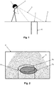
- Fig. 1 shows a person with an augmented reality helmet 1 or AR-helmet 1, respectively.
- the AR-helmet 1 is comprising a camera 2, a display 3 and a control unit preferably at the camera.
- the control unit provides information in respect of camera position and orientation in the real world scenery. This information is derived from one or more motion tracking technologies, like a global navigation satellite systems (GNSS) e.g. GPS and/or a base station navigation and/or an accelerometer and/or a gyroscope and/or an inertial measurement unit (IMU) and/or a solid state compass and/or a structure-from-motion unit and/or a bundle adjustment unit and/or a Simultaneous Localization and Mapping (SLAM) unit.
- GNSS global navigation satellite systems
- IMU inertial measurement unit
- SLAM Simultaneous Localization and Mapping
- the control unit is providing image reference information to the current image of the camera.
- the image reference information is comprising a camera position and a camera orientation in the real world scenery at the time of taking the image and internal parameters of the camera, e.g. characterizing the optical center, the focal length, and or other imaging relevant parameters of the camera setup.
- the camera 2 has a field of view 4.
- the field of view 4 is directed to a street 5 with a manhole being the visual part of a subsurface infrastructure 6.
- the manhole is used as anchor element 7 of the subsurface infrastructure 6.
- Fig. 2 shows the image 8 taken by the camera 2 showing the street 5 and the anchor element image 7a.
- a three dimensional information 8 of a subsurface infrastructure 6 is provided, e.g. from an offline or online storage media, from a GIS- or BIM database or the like, for example in form of CAD-data.
- a two dimensional projection to the image sensor is added or combined to the image 8.
- This projection of the subsurface infrastructure 6 includes an anchor element projection 7b. Overlaying the image 8 and the projection of the subsurface infrastructure 6 will therein likely show a mismatch of the anchor element image 7a and the anchor element projection 7b.
- Fig. 3 shows the anchor element image 7a and the anchor element projection 7b of Fig. 2 .
- the center of the anchor element projection 7b is a projection position 7b' of the anchor element 7.
- the center of the anchor element image 7a is an image position 7a' of the anchor element 7.
- the position difference 10 between the image position 7a' and the projection position 7b' of the same anchor element 7 is compensated for matching and overlaying the two dimensional projection derived from the three dimensional information 9 of the subsurface infrastructure 6 with the image 8.
- Such can comprise an adaption or correction of the image reference information used in the projecting to compensate a difference between the image position and the projection position of the same anchor element - resulting in shift, rotation and/or scaling of the projection in such a way that there is a visual match of the anchor element(s) in both.
- Fig. 4 shows an improved augmented view 11 of the image 6 and the matched two dimensional projection of the subsurface infrastructure 6.
- This improved view 11 is provided at the display 3 of the augmented reality helmet 1.
- the anchor element image 7a and the anchor element projection 7b are fitting perfectly and therefore showing the anchor element 7.
- the shown two dimensional projection of the three dimensional information 9 of the subsurface infrastructure 6 is visualizing the subsurface infrastructure 6 in the real world scenery.
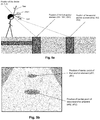
- FIG. 5a the position and orientation of the AR device (X,Y,Z, yaw, pitch, roll) and the position (XA1, YA1, ZA1) of a first anchor element (near the user of the AR device) and the position (XA2, YA2, ZA2) of a second anchor element (farther away from the user) are shown, both anchor elements embodied in the example as man hole covers.
- Fig. 5b the corresponding image view with position (xA1, yA1) of a center point of the first anchor element and position (xA2, yA2) of a center point of the second anchor element is shown.
- the accuracy of only a subset of this parameters can be improved.
- the projection of the anchor elements can be vertically and horizontally shifted to their positions as detected in the image. Basically, this would correspond to adjust the pitch (vertical rotation) and yaw (horizontal rotation) of the AR device.
- Fig. 6 several representations of a light switch / power socket combination depending on the construction progress are shown in the upper part i.e. different visual appearances of a light switch / power socket combination depending on the construction progress, and corresponding object segmentations in the lower part of Fig. 6 .
- the detection model can be trained on all of these variations in order to robustly detect the anchor element independently from the construction state. Furthermore, the detection model can be combined with an object segmentation model determining the accurate shape of the anchor element.
- the shape of the anchor element can then be matched with the two dimensional anchor element projection of the same element as shown in Fig. 7 , illustrating in the upper part (from left to right) the steps of 7A: detection of the object, 7B: segmentation of the object (optional), and 7C: determination of offset using a projection of an object shape from a model (7D) and 7E: compensation of the offset (lower left part of Fgi. 7).
- the projection can be directly matched with the bounding box resulting from the object detection without the segmentation step. In both cases, the matching can be based on minimizing the deviations between the contours resulting from the detected object and the projection.
- a center point can be derived as shown in Fig. 8 , illustrating in the upper part (from left to right) the steps of 8A: detection of an object, 8B: determination of a center point and 8C: determination of an offset using a projection of center point of the object from a model based on reference information (8D).
- this center point is matched with the two dimensional anchor element projection representing the object center of the three dimensional information and used for compensation (8E) of the offset as indicated in the lower part of Fig. 8 .
- Fig. 9 an example of a compensation of the offset is shown.
- a deviation of the anchor object i.g. a light switch / power socket combination and the reprojection of the corresponding element from the subsurface information is observable (detected offset arrow).
- the hidden electrical cables are visualized (dashed lines).
- an offset is detected, which is then compensated.
- the augmented view after compensation of the offset is shown: the view of the light switch / power socket combination is matched to the center point (black dot) of the model.
Landscapes
- Engineering & Computer Science (AREA)
- Physics & Mathematics (AREA)
- Theoretical Computer Science (AREA)
- General Engineering & Computer Science (AREA)
- General Physics & Mathematics (AREA)
- Software Systems (AREA)
- Computer Hardware Design (AREA)
- Computer Graphics (AREA)
- Human Computer Interaction (AREA)
- Optics & Photonics (AREA)
- Multimedia (AREA)
- Signal Processing (AREA)
- Processing Or Creating Images (AREA)
Abstract
Description
- The present invention relates generally to a method for deriving an augmented view of subsurface infrastructure according to the preamble of
claim 1, as well as to a mobile augmented reality viewing device and a computer program product. - The present invention relates to a determination of structures which are at least partially hidden beneath a solid surface. In particular, the invention is related to a visualization of structures beneath an opaque surface in an augmented reality (AR) view. Such subsurface structures can for example be pipework, cables, ducts, channels, tunnels, vents, connectors, bunkers or other subsurface construction work.
- When working through an opaque surface, there is often the question what part of a hidden structure could or should be hit. Not only in case of inspection or repair of subsurface utilities, like ruptured, corroded, worn or leaking pipes or wirings, but also when planning and adding new or additional utilities. Also, when general construction work is done, an occupation and/or clearance of a worksite with respect to subsurface facilities has to be checked and verified in advance of operations to be performed. For example, it has to be derived in which areas caution is needed. Another question is whether subsurface facilities are live or not, if there are orphaned structures that can be destroyed without any harm, which of the subsurface structures have to be shut down before work and where and how to shut them down, etc. Such need not only arises for off-site planning but also live at-site, before and/or during work.
- Although plan or map data is available and/or such data can be derived by detection equipment like cable-detectors, cable-locators, cable-tracers, cable avoidance tools (CAT), penetrating radar, metal detectors, sonars, etc. - such available data tends to be difficult to read at site and often requires a usage of surveying equipment to spatially reference the plan to the real world.
- Recently, so-called augmented reality (AR) technology is used for doing so. Therein, an actual view of the real world - e.g. captured by a 2D or 3D camera or by a see-though device - is visually overlaid by computer generated graphics and renderings to augment the real world view with additional virtual information. Computational frameworks and software development kits (SDK) like the "ARKit", "ARCore", "Wikitude", "Vuforia", "ARToolKit" etc. are providing a wide range of basic functionalities, enabling the implementation of AR-views which can be used in the present invention, e.g. on a mobile device like a smartphone, tablet computer, virtual reality glasses, head-mounted displays (HMD), head-up displays (HUD), EyeTaps or the like.
- The mobile device comprises one or more motion tracking technologies for deriving a location and orientation in space, like global navigation satellite systems (GNSS) e.g. GPS, accelerometers, gyroscopes or solid state compasses.
- For example, a still image, a live video or an image stream is captured by a camera, spatially referenced in its environment and overlaid by a virtually rendered object on top of the video or image(s). For example,
WO 2018/160921 mentions generating a superimposed image of an implement of a material moving machine, a virtual trench and underground features. In the field of excavators, the requirement for overlaying accuracy is much lower than in other fields. Therefore, the disclosed solution is limited to the field of excavators. -
US 2014/210856 A1 is disclosing overlaying an image of a wall or a ceiling with an image of a 3D digital model of internal elements e.g. pipes or conduits. Markers have to be placed at predetermined coordinates on an external element of the wall or ceiling. The markers on the image allow a precise overlaying of the image and the 3D digital model. The need for placing markers on the wall or ceiling is not acceptable in many applications and it is very time consuming. - It is therefore an object of the invention to find a solution for precise overlaying images and 3D digital models without the need for applying markers.
- The object is achieved by realizing the features of the independent claims. Features, which further develop the invention in an alternative or advantageous manner are described in the dependent patent claims.
- Inventive providing of an augmented view of a real world scenery and an occluded subsurface infrastructure is comprising:
- ∘ taking at least one image of the real world scenery by a camera with an image sensor,
- ∘ providing image reference information to the at least one image, wherein the image reference information is comprising a camera position and a camera orientation in the real world scenery at the time of taking the at least one image and optionally also internal parameters of the camera characterizing the optical center and the focal length (as an alternative without such internal parameters, an iterative approach is chosen wherein for example the image is shifted by some pixels till it fits),
- ∘ providing three dimensional information of a subsurface infrastructure,
- ∘ deriving from the three dimensional information of the subsurface infrastructure a two dimensional projection at the image sensor, wherein the two dimensional projection is made by using the reference information of the at least one image, and
- ∘ comparing a projection position of a two dimensional projection of at least one anchor element of the subsurface infrastructure being visible on the at least one image of the real world scenery with an image position of the same anchor element on the at least one image, and
- ∘ using a difference between the image position and the projection position of the same anchor element from the comparing for matching and overlaying the two dimensional projection derived from the three dimensional information of the subsurface infrastructure with the at least one image and thereby providing the augmented view.
- The inventive solution can be implemented in the form of a method, a mobile device or a computer program product.
- Augmented viewing of overlaid images of real world scenery and occluded subsurface infrastructure is applied in areas with good and with poor localization of the camera taking the images. For example, in areas of limited reception of the GNSS signals or in indoor environments the determined position with respect to the geo-referenced 3d-model of the subsurface infrastructure might be inaccurate. This leads to deviations between the overlaid information and the live-view image captured with the camera.
- The camera position and/or the camera orientation in the real world scenery can be deduced from data of a navigation system like a navigation satellite system (GPS) and/or of a base station navigation and/or of an accelerometer and/or of a gyroscope and/or of an inertial measurement unit (IMU) and/or of a solid state compass and/or of a structure-from-motion unit and/or of a bundle adjustment unit and/or of a Simultaneous Localization and Mapping (SLAM) unit and/or of a spatial reference recognition unit using existing reference points with defined spatial positions.
- According to the invention, misalignment due to inaccurate camera position and orientation information can be reduced or prevented by deriving position and/or orientation information of visible elements of the geo-referenced 3d-model of the subsurface infrastructure. Subsurface infrastructure, e.g. sewerage or electrical installations, have connecting elements, e.g. manholes in case of a sewerage or power sockets and light switches in case of an electrical installation, which are visible in images of the real world scenery. Such visible elements can be found on at least one image taken by the camera and in the geo-referenced 3d-model. These visible elements are called anchor elements. The anchor elements can therein also be selected from other visible structures that are comprised in the image and available in a geo-referenced 3d-model of infrastructure, not necessarily only the elements of the structure to be actually shown in the AR-view. For example, one or more sewer-manholes can be used as anchors for e.g. showing an underground gas-pipe, when georeferenced 3D data of both is available - although the sewer system is not shown in the AR-view at all, or only the anchor elements of the sewer system are shown.
- A two dimensional, in particular virtual, projection of the three dimensional information of the subsurface infrastructure to the image sensor of the camera is made in accordance with the present camera position and orientation information and with internal parameters of the camera, e.g. characterizing the cameras optical center, focal length, image distortions, etc. If the existing camera position and orientation information is not accurate, then an anchor element in the two dimensional projection of the subsurface infrastructure on the image sensor has a position and/or orientation that differs from the position and/or orientation of the anchor element in the image taken by the camera.
- Misalignment of an augmented view with the image and the overlaid subsurface infrastructure is prevented according to the invention by comparing the projection position of the two dimensional projection of at least one anchor element of the subsurface infrastructure being visible on the at least one image of the real world scenery with the image position of the same anchor element on the at least one image. The difference between the image position and the projection position of the same anchor element is compensated for matching and overlaying the two dimensional projection derived from the three dimensional information of the subsurface infrastructure with the at least one image and thereby providing an improved augmented view. The augmented view is thereby configured to provide the one or more anchor element(s) - and consequently of all of the augmented subsurface infrastructure in the mixed reality view - with a spatially correctly matched alignment of the image and the projection. Preferably, such is done substantially in real time when providing the augmented view so that the matching is kept stable, also when the AR-viewing device is moved and/or when the position and/or orientation sensors of the device are drifting.
- The inventive solution allows improving augmented view without time consuming placing of markers at selected positions in the real world scenery.
- In a preferred embodiment, the at least one anchor element of the subsurface infrastructure being visible on the at least one image of the real world scenery is assigned to one of several predefined anchor element categories with corresponding position and shape characteristics in such a way that the anchor element can be assigned to an anchor element category independently of its construction state. The predefined anchor element categories allow a recognition procedure for finding anchor elements in the image and/or in the two dimensional projection of the subsurface infrastructure, no matter which construction progress or development state is actually present. In other words, an anchor object can be robustly or reliably recognized or detected as a specific anchor object type be it in an early increment (e.g. just a socket of an installation) or in its final, finished state (installation completed) or somewhere in between. The recognizing and finding is established automatically by an identifier and/or classifier in an artificial intelligence system, e.g. comprising a machine learned neural network. A starting point for the finding and/or for the categories can therein be derived from the three dimensional information of a subsurface infrastructure, respectively of its two dimensional projection in vicinity. In an embodiment, the anchor elements position, category and/or shape can be directly derived from the three dimensional information of a subsurface infrastructure in the projecting process, but in another embodiment, a (preferably substantially the same) routine for recognizing and/or finding of the anchor element can be applied to both, the image and the two dimensional projection. The size and the form of an anchor element on the image or on the two dimensional projection depends on the position of the camera. Recognizing an anchor element and assigning the anchor element to one of the predefined anchor element categories can be improved with shape characteristics including shape information in different scales and/or in different projections.
- The position and shape characteristics of at least one of the predefined anchor element categories can include a central position and a shape information, wherein the shape information can e.g. comprise at least one point located at a circumference line of the anchor element. The shape information can also comprise a section of a circumference line or a closed circumference line. Position and shape characteristics of the predefined anchor element category corresponding to an anchor element found in the image and/or in the two dimensional projection of the subsurface infrastructure can be adjusted to the size and preferably to the perspective distortion of the found anchor element such that the position of the found anchor element can be deduced for the image and the two dimensional projection.
- In a preferred embodiment, the position and shape characteristics of at least one of the predefined anchor element categories comprise at least information in respect of an axis passing through the central position and indicating a maximum extension of the predefined anchor element. This information about the direction of a maximum extension allows determining an orientation of a corresponding anchor element on the image and/or on the projection of the subsurface infrastructure.
- Preferred embodiments use the position and shape characteristics assigned to the at least one anchor element to determine a projection position and/or a projection orientation and an image position and/or an image orientation of the at least one anchor element on the two dimensional projection of the image sensor and on the at least one image, respectively. If the difference between the image position and the projection position and/or the difference between the image orientation and the projection orientation is below a predefined maximum difference, then the difference between the image position and the projection position and/or the difference between the image orientation and the projection orientation is used for providing a matched two dimensional projection. Applying matching only for differences below a predefined maximum difference prevents matching with different anchor elements - which could result in wrong matchings.
- In a simple embodiment, matching and overlaying the two dimensional projection derived from the three dimensional information of the subsurface infrastructure with the at least one image and thereby providing an improved augmented view comprises translating and/or rotating, optionally also scaling, the two dimensional projection derived from the three dimensional information of the subsurface infrastructure by the deduced differences of position and/or orientation.
- In a further embodiment, matching and overlaying the two dimensional projection derived from the three dimensional information of the subsurface infrastructure with the at least one image and thereby providing an improved augmented view comprises improving image reference information of the at least one image by adjusting the camera position and/or the camera orientation in the image reference information of the real world scenery based on the difference between the image position and/or orientation and the projection position and/or orientation of the same anchor element, and deriving, in particular calculating or rendering, from the three dimensional information of the subsurface infrastructure a two dimensional projection from a point of view equal to the image sensor of the camera and preferably with a same field of view and imaging characteristic. Therein the two dimensional projection is made by using the improved reference information of the at least one image or by using the improved position and/or orientation of the camera, respectively - as derived by the difference.
- A mobile augmented reality viewing device and a computer program product with program code being stored on a machine readable medium or embodied as an electromagnetic wave can be configured to execute the described embodiments of the method according to the invention.
- In the providing of image reference information, e.g. localizing a displayed real world scenery can comprise deriving spatial reference information for the field of view of the image, in particular deriving six degree of freedom spatial reference information of the image or camera, respectively. The spatial reference information can comprise data from an inertial measurement unit (IMU), from a navigation system like a local and/or global navigation satellite system (GPS), a base station navigation and/or a Simultaneous Localization and Mapping (SLAM) unit.
- If no navigation system is available, then the spatial reference information will preferably be derived by a Visual SLAM method. Visual SLAM allows constructing or updating a map of an unknown environment while simultaneously keeping track of the camera unit's location and orientation within it. The spatial reference information allows deriving location information for the field of view of the camera image. Visual SLAM (VSLAM) is evaluating the images from the camera.
- The viewing device can also comprise a depth camera, like a time of flight camera, a stereo camera, a range image camera, a laser scanning unit, a structured light 3D scanner, etc. There can also be additional auxiliary cameras besides a main view camera mentioned above, which are pointing out from the viewing device to cover a maximum area around the operator, like at a Head Mounted Display (HMD). The deriving of the location information can in particular comprise sensor fusion of multiple of such sensors which can be configured to derive positional or navigation information, e.g. also to overcome instances when one or more of the multiple sensors is blocked or has insufficient data. The deriving of the spatial reference, image processing and/or IMU-evaluation can for example be provided by computational frameworks of augmented reality toolboxes.
- In the providing of three dimensional information, e.g. geospatial information of the subsurface infrastructure can be derived from a storage, for example from a subsurface infrastructure-, BIM- or geospatial- database, e.g. via Open Geospatial Consortium (OGC), Web Map Service (WMS), Web Feature Service (WFS), Web Coverage Service (WGS) or others, preferably on-line by a wireless networking interface or from a local storage unit. The method according to the invention is then calculating a projection of the subsurface infrastructure with a same virtual field of view and perspective as the field of view of the image from the camera.
- The augmented view combining the image from the camera and the projection of the subsurface infrastructure can be displayed by a two or three dimensional or stereo vision unit.
- The present invention is preferably configured to provide an auto-adaptive AR-view that is rendered live or in real time in the field, based on a present real world image of video stream. Therein, a camera loopback is provided - in which a video feedback from the real world camera images is used.
- Visual effects can be applied to the projection of the subsurface infrastructure to improve the recognition of the augmented reality view. For example, the subsurface structure can be displayed like looking on it as under a glass-like cover, in such a way that the subsurface structure is visible for a user - but at the same time the user sees the surface covering the subsurface structure. In other words, the surface covering the subsurface structures is turned into a virtual glass or frosted glass cover. For example, the projection of the subsurface structure can be overlaid to at least portions of the image from the camera in a faded and/or color filtered, semi-transparent form.
- A frame-by-frame processing in real time can provide a realistic provision of the augmented view. The sun or light conditions might change quickly, wherefore the system needs to adapt substantially in real-time to maintain a realistic effect, for example when clouds move in front of the sun, when leaves of a tree provide a sophisticated and ever-moving shadow pattern on the ground, etc.
- The features of the subsurface infrastructure that are visible in the image can be automatically detected, identified and matched with an according feature from the information of subsurface infrastructure by a computational unit.
- The embodiments of the present invention are configured to spatially align anchor elements of the subsurface infrastructure to the corresponding anchor elements on images. For example, such image processing can also comprise specific object detection algorithms configured for detecting instances of semantic objects of a subsurface utility class, like an algorithm that uses machine learning trained on real world and/or simulated image data, such as Semantic Soft Segmentation, etc.
- For example, features or portions of subsurface infrastructure which are at or in front of the surface, such as a drain cover, fireplug, lamppost, terminal box, duct cover, etc. can be detected and identified in the real world image and dimensionally surveyed in their location in the real world image.
- The reference information indicating the position (X, Y, Z) and orientation (roll, pitch, yaw) can be determined by a sensor fusion of e.g. GNSS, inertial measurement unit, magnetometer, etc. Since these sensors might suffer from systematic errors, e.g. GNSS multipath, distortions of the magnetic field caused by large construction machines, etc., the resulting reference information might not be accurate enough for an accurate projection of the subsurface infrastructure.
- In order to improve the accuracy of the reference information the at least one detected anchor element can be introduced as ground control point as known from photogrammetry into the optimization process that results in a more accurate position and orientation of the device. In other words, the reference information, i.e. the coordinates X, Y, Z and orientation angles roll, pitch, yaw, is fused with the image coordinates xA, yA and the corresponding world coordinates XA, YA, ZA of the at least one anchor element to compute more accurate values for X, Y, Z, roll, pitch, and yaw. Applying these values in the projection of the subsurface infrastructure leads to smaller deviations with respect to the real objects in the augmented view.
- In the fusion of the reference information with and the measurements related to the anchor elements a weighting based on the accuracy of the corresponding measurements can be applied.
- Methods, devices, and computer programs according to the invention are described or explained in more detail below, purely by way of example, with reference to working examples shown schematically in the drawing. Specifically, shown is in
-
Fig. 1 a schematic side view of a person with an augmented reality helmet standing on a street with a manhole; -
Fig. 2 an image taken by the camera of the augmented reality helmet, wherein the two dimensional projection of a subsurface infrastructure is added to the image; -
Fig. 3 an extract ofFig. 2 .; -
Fig. 4 an improved augmented view; -
Fig. 5a,b examples for positions of an AR device and anchor elements; -
Fig. 6 examples for object representations and segmentations; -
Fig.7 examples for anchor element matching; -
Fig. 8 an example of object segmentation; and -
Fig. 9 an example of a compensation of the offset is shown. - The diagrams of the figures should not be considered as being drawn to scale. Where appropriate, the same reference signs are used for the same features or for features with similar functionalities. Different indices to reference signs are used to differentiate between different embodiments of a feature which are exemplary shown.
-
Fig. 1 shows a person with anaugmented reality helmet 1 or AR-helmet 1, respectively. The AR-helmet 1 is comprising acamera 2, adisplay 3 and a control unit preferably at the camera. The control unit provides information in respect of camera position and orientation in the real world scenery. This information is derived from one or more motion tracking technologies, like a global navigation satellite systems (GNSS) e.g. GPS and/or a base station navigation and/or an accelerometer and/or a gyroscope and/or an inertial measurement unit (IMU) and/or a solid state compass and/or a structure-from-motion unit and/or a bundle adjustment unit and/or a Simultaneous Localization and Mapping (SLAM) unit. - The control unit is providing image reference information to the current image of the camera. The image reference information is comprising a camera position and a camera orientation in the real world scenery at the time of taking the image and internal parameters of the camera, e.g. characterizing the optical center, the focal length, and or other imaging relevant parameters of the camera setup.
- The
camera 2 has a field ofview 4. In the shown situation the field ofview 4 is directed to astreet 5 with a manhole being the visual part of asubsurface infrastructure 6. The manhole is used asanchor element 7 of thesubsurface infrastructure 6. -
Fig. 2 shows theimage 8 taken by thecamera 2 showing thestreet 5 and theanchor element image 7a. A threedimensional information 8 of asubsurface infrastructure 6 is provided, e.g. from an offline or online storage media, from a GIS- or BIM database or the like, for example in form of CAD-data. Of the provided threedimensional information 9 of the subsurface infrastructure 6 a two dimensional projection to the image sensor is added or combined to theimage 8. This projection of thesubsurface infrastructure 6 includes ananchor element projection 7b. Overlaying theimage 8 and the projection of thesubsurface infrastructure 6 will therein likely show a mismatch of theanchor element image 7a and theanchor element projection 7b. -
Fig. 3 shows theanchor element image 7a and theanchor element projection 7b ofFig. 2 . The center of theanchor element projection 7b is aprojection position 7b' of theanchor element 7. The center of theanchor element image 7a is animage position 7a' of theanchor element 7. Theposition difference 10 between theimage position 7a' and theprojection position 7b' of thesame anchor element 7 is compensated for matching and overlaying the two dimensional projection derived from the threedimensional information 9 of thesubsurface infrastructure 6 with theimage 8. Such can comprise an adaption or correction of the image reference information used in the projecting to compensate a difference between the image position and the projection position of the same anchor element - resulting in shift, rotation and/or scaling of the projection in such a way that there is a visual match of the anchor element(s) in both. -
Fig. 4 shows an improvedaugmented view 11 of theimage 6 and the matched two dimensional projection of thesubsurface infrastructure 6. Thisimproved view 11 is provided at thedisplay 3 of theaugmented reality helmet 1. On the improved augmentedview 11 theanchor element image 7a and theanchor element projection 7b are fitting perfectly and therefore showing theanchor element 7. The shown two dimensional projection of the threedimensional information 9 of thesubsurface infrastructure 6 is visualizing thesubsurface infrastructure 6 in the real world scenery. - In
Fig. 5a , the position and orientation of the AR device (X,Y,Z, yaw, pitch, roll) and the position (XA1, YA1, ZA1) of a first anchor element (near the user of the AR device) and the position (XA2, YA2, ZA2) of a second anchor element (farther away from the user) are shown, both anchor elements embodied in the example as man hole covers. InFig. 5b the corresponding image view with position (xA1, yA1) of a center point of the first anchor element and position (xA2, yA2) of a center point of the second anchor element is shown. Alternatively to adjusting all the six degrees-of-freedom, i.e. X, Y, Z, roll, pitch, and yaw, the accuracy of only a subset of this parameters can be improved. For instance, the projection of the anchor elements can be vertically and horizontally shifted to their positions as detected in the image. Basically, this would correspond to adjust the pitch (vertical rotation) and yaw (horizontal rotation) of the AR device. - In
Fig. 6 , several representations of a light switch / power socket combination depending on the construction progress are shown in the upper part i.e. different visual appearances of a light switch / power socket combination depending on the construction progress, and corresponding object segmentations in the lower part ofFig. 6 . The detection model can be trained on all of these variations in order to robustly detect the anchor element independently from the construction state. Furthermore, the detection model can be combined with an object segmentation model determining the accurate shape of the anchor element. - The shape of the anchor element can then be matched with the two dimensional anchor element projection of the same element as shown in
Fig. 7 , illustrating in the upper part (from left to right) the steps of 7A: detection of the object, 7B: segmentation of the object (optional), and 7C: determination of offset using a projection of an object shape from a model (7D) and 7E: compensation of the offset (lower left part of Fgi. 7). Alternatively as shown in the lower right part (7B1), the projection can be directly matched with the bounding box resulting from the object detection without the segmentation step. In both cases, the matching can be based on minimizing the deviations between the contours resulting from the detected object and the projection. - Alternatively, from the bounding box or the shape resulting from the object segmentation a center point can be derived as shown in
Fig. 8 , illustrating in the upper part (from left to right) the steps of 8A: detection of an object, 8B: determination of a center point and 8C: determination of an offset using a projection of center point of the object from a model based on reference information (8D). Thus, this center point is matched with the two dimensional anchor element projection representing the object center of the three dimensional information and used for compensation (8E) of the offset as indicated in the lower part ofFig. 8 . - In
Fig. 9 , an example of a compensation of the offset is shown. In the left image, showing an augmented view before compensation, a deviation of the anchor object, i.g. a light switch / power socket combination and the reprojection of the corresponding element from the subsurface information is observable (detected offset arrow). Moreover, the hidden electrical cables are visualized (dashed lines). Based on the matching of the detected light switch / power socket combination in the image and the corresponding two dimensional anchor element projection an offset is detected, which is then compensated. In the right image, the augmented view after compensation of the offset is shown: the view of the light switch / power socket combination is matched to the center point (black dot) of the model.
Claims (15)
- A method for providing an augmented view (11) of a real world scenery and of an occluded subsurface infrastructure (6), comprising:∘ taking at least one image (8) of the real world scenery by a camera (2) with an image sensor,∘ providing image reference information to the at least one image (8), wherein the image reference information is comprising a camera position and a camera orientation in the real world scenery at the time of taking the at least one image (8),∘ providing three dimensional information (9) of a subsurface infrastructure (6), and∘ deriving from the three dimensional information (9) of the subsurface infrastructure (6) a two dimensional projection on the image sensor, wherein the two dimensional projection is made by using the reference information of the at least one image (8),characterized in thata projection position (7b') of a two dimensional anchor element projection (7b) of at least one anchor element (7) of the subsurface infrastructure (6) being visible on the at least one image (8) of the real world scenery is compared with an image position (7a') of the anchor element image (7a) of the anchor element (7) on the at least one image (8),wherein a difference (10) between the image position (7a') and the projection position (7b') of the same anchor element (7) is compensated for matching and overlaying the two dimensional projection derived from the three dimensional information (9) of the subsurface infrastructure (6) with the at least one image (8) and thereby providing an improved augmented view (11).
- Method according to claim 1,
characterized in that
the at least one anchor element (7) of the subsurface infrastructure (6), being visible on the at least one image (8) of the real world scenery and/or in the two dimensional projection at the image sensor, is assigned to one of several predefined anchor element categories based on a machine learned identifier and/or classifier unit, preferably comprising a deep learning e.g. with convolutional neural networks, in such a way that the anchor element (7) can be assigned to an anchor element category independently of its construction state. - Method according to claim 1 or 2,
characterized in that
the at least one anchor element (7) of the subsurface infrastructure (6) being visible on the at least one image (8) of the real world scenery is assigned to one of several predefined anchor element categories with corresponding position and shape characteristics. - Method according to claim 3,
characterized in that
the shape characteristics include shape information in different scales and/or in different projections. - Method according to claim 3 or 4,
characterized in that
the position and shape characteristics of the predefined anchor element categories comprise a central position and a shape information, wherein the shape information is comprising at least one point located at a circumference line of the anchor element (7),
in particular wherein the position and shape characteristics of at least one of the predefined anchor element categories comprise at least one axis passing through the central position and indicating a maximum extension of the predefined anchor element (7). - Method according to one of claims 3 to 5,
characterized in that∘ the position and shape characteristics of at least one anchor element (7) of the subsurface infrastructure (6) are used to determine a projection position (7b') and an image position (7a') of the at least one anchor element (7) on the two dimensional projection of the image sensor and on the at least one image, respectively,∘ the difference (10) between the image position (7a') and the projection position (7b') is used for providing a matched two dimensional projection, only if the difference between the image position (7a') and the projection position (7b') is below a predefined maximum difference. - Method according to one of claims 3 to 6,
characterized in that∘ the position and shape characteristics of at least one anchor element (7) of the subsurface infrastructure (6) are used to determine a projection orientation and an image orientation of the at least one anchor element (7) on the two dimensional projection of the image sensor and on the at least one image (8) with corresponding position and shape characteristics,∘ the difference between the image orientation and the projection orientation is used for providing a matched two dimensional projection, only if the difference between the image orientation and the projection orientation is below a predefined maximum difference. - Method according to claim 6 or 7,
characterized in that
determining to an anchor element (7) the projection position (7b') and/or the projection orientation and the image position (7a') and/or image orientation comprises edge extraction and fitting of the extracted edge information to shape characteristics of one of the predefined anchor element categories. - Method according to one of claims 6 to 8,
characterized in that
determining to an anchor element (7) the projection position (7b') and/or the projection orientation and the image position (7a') and/or image orientation comprises least-squares template matching. - Method according to any one of claim 1 to 9,
characterized in that
matching and overlaying the two dimensional projection derived from the three dimensional information (9) of the subsurface infrastructure (6) with the at least one image (8) and thereby providing an improved augmented view (11) comprises translating and/or rotating the two dimensional projection derived from the three dimensional information (9) of the subsurface infrastructure (6). - Method according to any one of claim 1 to 9,
characterized in that
matching and overlaying the two dimensional projection derived from the three dimensional information (9) of the subsurface infrastructure (6) with the at least one image (8) and thereby providing an improved augmented view (11) comprises∘ improving image reference information to the at least one image (8) by adjusting the camera position and/or the camera orientation in the image reference information of the real world scenery based on the difference between the image position (7a) and the projection position (7b) of the same anchor element (7), and∘ deriving from the three dimensional information (9) of the subsurface infrastructure (6) a two dimensional projection at the image sensor, wherein the two dimensional projection is made by using the improved reference information of the at least one image (8). - Method according to claim 11,
characterized in that
improving image reference information to the at least one image (8) by adjusting the camera position and/or the camera orientation in the real world scenery comprises∘ deriving the position of the anchor element (7) from the three dimensional information (9) of the subsurface infrastructure (6), and∘ using the position of the anchor element (7) as reference position for improving the camera position and/or the camera orientation in the real world scenery. - Method according to any one of claim 1 to 12,
characterized in that
the camera position and/or the camera orientation in the real world scenery is deduced from data of a navigation system like a navigation satellite system (GPS) and/or of a base station navigation and/or of an accelerometer and/or of a gyroscope and/or of an inertial measurement unit (IMU) and/or of a solid state compass and/or of a structure-from-motion unit and/or of a bundle adjustment unit and/or of a Simultaneous Localization and Mapping (SLAM) unit and/or of a spatial reference recognition unit. - A mobile augmented reality viewing device configured to execute a method according to any one of claim 1 to 13.
- A computer program product with program code being stored on a machine readable medium or embodied as an electromagnetic wave, the program code being configured for the execution of at least one of the methods according to any one of claims 1 to 13.
Priority Applications (3)
| Application Number | Priority Date | Filing Date | Title |
|---|---|---|---|
| EP20157636.0A EP3865982B1 (en) | 2020-02-17 | 2020-02-17 | Augmented viewing of a scenery and subsurface infrastructure |
| CN202110180659.XA CN113269892B (en) | 2020-02-17 | 2021-02-08 | Method for providing augmented view, mobile augmented reality viewing device |
| US17/176,766 US11348321B2 (en) | 2020-02-17 | 2021-02-16 | Augmented viewing of a scenery and subsurface infrastructure |
Applications Claiming Priority (1)
| Application Number | Priority Date | Filing Date | Title |
|---|---|---|---|
| EP20157636.0A EP3865982B1 (en) | 2020-02-17 | 2020-02-17 | Augmented viewing of a scenery and subsurface infrastructure |
Publications (2)
| Publication Number | Publication Date |
|---|---|
| EP3865982A1 true EP3865982A1 (en) | 2021-08-18 |
| EP3865982B1 EP3865982B1 (en) | 2024-04-17 |
Family
ID=69631432
Family Applications (1)
| Application Number | Title | Priority Date | Filing Date |
|---|---|---|---|
| EP20157636.0A Active EP3865982B1 (en) | 2020-02-17 | 2020-02-17 | Augmented viewing of a scenery and subsurface infrastructure |
Country Status (3)
| Country | Link |
|---|---|
| US (1) | US11348321B2 (en) |
| EP (1) | EP3865982B1 (en) |
| CN (1) | CN113269892B (en) |
Cited By (1)
| Publication number | Priority date | Publication date | Assignee | Title |
|---|---|---|---|---|
| CN116258608A (en) * | 2023-05-15 | 2023-06-13 | 中铁水利信息科技有限公司 | Water conservancy real-time monitoring information management system integrating GIS and BIM three-dimensional technology |
Families Citing this family (4)
| Publication number | Priority date | Publication date | Assignee | Title |
|---|---|---|---|---|
| CN114549801B (en) * | 2022-04-25 | 2022-07-19 | 深圳市同立方科技有限公司 | AR augmented reality water supply and drainage project visualization method, device and system |
| WO2024081154A1 (en) * | 2022-10-12 | 2024-04-18 | Snap Inc. | Energy-efficient adaptive 3d sensing |
| AU2024204142A1 (en) * | 2023-06-26 | 2025-01-16 | Fieri Analytics Inc. | Deep neural network-based system for detection and classification of construction elements in construction engineering drawings |
| CN118378326B (en) * | 2024-04-22 | 2025-06-03 | 中铁一局集团有限公司 | Method for generating shelter range above tunnel |
Citations (6)
| Publication number | Priority date | Publication date | Assignee | Title |
|---|---|---|---|---|
| US20120127161A1 (en) * | 2010-09-02 | 2012-05-24 | Mark Wallbom | System, apparatus, and method for utilizing geographic information systems |
| US20140125668A1 (en) * | 2012-11-05 | 2014-05-08 | Jonathan Steed | Constructing augmented reality environment with pre-computed lighting |
| US20140210856A1 (en) | 2013-01-30 | 2014-07-31 | F3 & Associates, Inc. | Coordinate Geometry Augmented Reality Process for Internal Elements Concealed Behind an External Element |
| US20170046877A1 (en) * | 2015-08-14 | 2017-02-16 | Argis Technologies, LLC | Augmented visualization system for hidden structures |
| WO2018160921A1 (en) | 2017-03-03 | 2018-09-07 | Caterpillar Trimble Control Technologies Llc | Augmented reality display for material moving machines |
| WO2020030948A1 (en) * | 2018-08-08 | 2020-02-13 | Abyssal S.A. | System and method of operation for remotely operated vehicles with improved position estimation |
Family Cites Families (2)
| Publication number | Priority date | Publication date | Assignee | Title |
|---|---|---|---|---|
| US20130084838A1 (en) * | 2011-10-03 | 2013-04-04 | Geospatial Holdings, Inc. | System, method, and apparatus for viewing underground structures |
| CN105844714A (en) * | 2016-04-12 | 2016-08-10 | 广州凡拓数字创意科技股份有限公司 | Augmented reality based scenario display method and system |
-
2020
- 2020-02-17 EP EP20157636.0A patent/EP3865982B1/en active Active
-
2021
- 2021-02-08 CN CN202110180659.XA patent/CN113269892B/en active Active
- 2021-02-16 US US17/176,766 patent/US11348321B2/en active Active
Patent Citations (6)
| Publication number | Priority date | Publication date | Assignee | Title |
|---|---|---|---|---|
| US20120127161A1 (en) * | 2010-09-02 | 2012-05-24 | Mark Wallbom | System, apparatus, and method for utilizing geographic information systems |
| US20140125668A1 (en) * | 2012-11-05 | 2014-05-08 | Jonathan Steed | Constructing augmented reality environment with pre-computed lighting |
| US20140210856A1 (en) | 2013-01-30 | 2014-07-31 | F3 & Associates, Inc. | Coordinate Geometry Augmented Reality Process for Internal Elements Concealed Behind an External Element |
| US20170046877A1 (en) * | 2015-08-14 | 2017-02-16 | Argis Technologies, LLC | Augmented visualization system for hidden structures |
| WO2018160921A1 (en) | 2017-03-03 | 2018-09-07 | Caterpillar Trimble Control Technologies Llc | Augmented reality display for material moving machines |
| WO2020030948A1 (en) * | 2018-08-08 | 2020-02-13 | Abyssal S.A. | System and method of operation for remotely operated vehicles with improved position estimation |
Cited By (2)
| Publication number | Priority date | Publication date | Assignee | Title |
|---|---|---|---|---|
| CN116258608A (en) * | 2023-05-15 | 2023-06-13 | 中铁水利信息科技有限公司 | Water conservancy real-time monitoring information management system integrating GIS and BIM three-dimensional technology |
| CN116258608B (en) * | 2023-05-15 | 2023-08-11 | 中铁水利信息科技有限公司 | Water conservancy real-time monitoring information management system integrating GIS and BIM three-dimensional technology |
Also Published As
| Publication number | Publication date |
|---|---|
| EP3865982B1 (en) | 2024-04-17 |
| US11348321B2 (en) | 2022-05-31 |
| CN113269892B (en) | 2024-04-23 |
| CN113269892A (en) | 2021-08-17 |
| US20210256770A1 (en) | 2021-08-19 |
Similar Documents
| Publication | Publication Date | Title |
|---|---|---|
| EP3865982B1 (en) | Augmented viewing of a scenery and subsurface infrastructure | |
| Son et al. | Real-time vision-based warning system for prevention of collisions between workers and heavy equipment | |
| US10997785B2 (en) | System and method for collecting geospatial object data with mediated reality | |
| CN109556580B (en) | Surveying instrument, AR system and method for positioning an AR device relative to a reference frame | |
| Behzadan et al. | Augmented reality visualization: A review of civil infrastructure system applications | |
| EP3246660B1 (en) | System and method for referencing a displaying device relative to a surveying instrument | |
| US8315425B2 (en) | Method for comparison of 3D computer model and as-built situation of an industrial plant | |
| US10412594B2 (en) | Network planning tool support for 3D data | |
| Hansen et al. | Augmented reality for subsurface utility engineering, revisited | |
| US20220282967A1 (en) | Method and mobile detection unit for detecting elements of infrastructure of an underground line network | |
| Hübner et al. | Marker-based localization of the microsoft hololens in building models | |
| EP3748583A1 (en) | Subsurface utility visualization | |
| US20120127161A1 (en) | System, apparatus, and method for utilizing geographic information systems | |
| US20220138467A1 (en) | Augmented reality utility locating and asset management system | |
| US10890447B2 (en) | Device, system and method for displaying measurement gaps | |
| US20130113897A1 (en) | Process and arrangement for determining the position of a measuring point in geometrical space | |
| JP7845747B2 (en) | Surveying support system, information display terminal, surveying support method, and surveying support program | |
| KR102097416B1 (en) | An augmented reality representation method for managing underground pipeline data with vertical drop and the recording medium thereof | |
| JP5669438B2 (en) | Object management image generation apparatus and object management image generation program | |
| CN117437370A (en) | High-voltage cable positioning method, device and equipment based on mixed reality 3D modeling | |
| CN117934729B (en) | Real-time three-dimensional projection fusion method for oil-gas field video monitoring | |
| CN118331474B (en) | Interactive method for resolving camera external orientation element based on three-dimensional model | |
| CA3056834C (en) | System and method for collecting geospatial object data with mediated reality | |
| US12211223B2 (en) | System and method for setting a viewpoint for displaying geospatial data on a mediated reality device using geotags | |
| Sauer et al. | Occlusion handling in augmented reality user interfaces for robotic systems |
Legal Events
| Date | Code | Title | Description |
|---|---|---|---|
| PUAI | Public reference made under article 153(3) epc to a published international application that has entered the european phase |
Free format text: ORIGINAL CODE: 0009012 |
|
| STAA | Information on the status of an ep patent application or granted ep patent |
Free format text: STATUS: THE APPLICATION HAS BEEN PUBLISHED |
|
| AK | Designated contracting states |
Kind code of ref document: A1 Designated state(s): AL AT BE BG CH CY CZ DE DK EE ES FI FR GB GR HR HU IE IS IT LI LT LU LV MC MK MT NL NO PL PT RO RS SE SI SK SM TR |
|
| STAA | Information on the status of an ep patent application or granted ep patent |
Free format text: STATUS: REQUEST FOR EXAMINATION WAS MADE |
|
| 17P | Request for examination filed |
Effective date: 20220215 |
|
| RBV | Designated contracting states (corrected) |
Designated state(s): AL AT BE BG CH CY CZ DE DK EE ES FI FR GB GR HR HU IE IS IT LI LT LU LV MC MK MT NL NO PL PT RO RS SE SI SK SM TR |
|
| GRAP | Despatch of communication of intention to grant a patent |
Free format text: ORIGINAL CODE: EPIDOSNIGR1 |
|
| STAA | Information on the status of an ep patent application or granted ep patent |
Free format text: STATUS: GRANT OF PATENT IS INTENDED |
|
| INTG | Intention to grant announced |
Effective date: 20231206 |
|
| RIN1 | Information on inventor provided before grant (corrected) |
Inventor name: METZLER, BERNHARD |
|
| GRAS | Grant fee paid |
Free format text: ORIGINAL CODE: EPIDOSNIGR3 |
|
| GRAA | (expected) grant |
Free format text: ORIGINAL CODE: 0009210 |
|
| STAA | Information on the status of an ep patent application or granted ep patent |
Free format text: STATUS: THE PATENT HAS BEEN GRANTED |
|
| AK | Designated contracting states |
Kind code of ref document: B1 Designated state(s): AL AT BE BG CH CY CZ DE DK EE ES FI FR GB GR HR HU IE IS IT LI LT LU LV MC MK MT NL NO PL PT RO RS SE SI SK SM TR |
|
| REG | Reference to a national code |
Ref country code: GB Ref legal event code: FG4D |
|
| REG | Reference to a national code |
Ref country code: CH Ref legal event code: EP |
|
| REG | Reference to a national code |
Ref country code: DE Ref legal event code: R096 Ref document number: 602020028994 Country of ref document: DE |
|
| REG | Reference to a national code |
Ref country code: IE Ref legal event code: FG4D |
|
| REG | Reference to a national code |
Ref country code: LT Ref legal event code: MG9D |
|
| REG | Reference to a national code |
Ref country code: NL Ref legal event code: MP Effective date: 20240417 |
|
| REG | Reference to a national code |
Ref country code: AT Ref legal event code: MK05 Ref document number: 1677863 Country of ref document: AT Kind code of ref document: T Effective date: 20240417 |
|
| PG25 | Lapsed in a contracting state [announced via postgrant information from national office to epo] |
Ref country code: NL Free format text: LAPSE BECAUSE OF FAILURE TO SUBMIT A TRANSLATION OF THE DESCRIPTION OR TO PAY THE FEE WITHIN THE PRESCRIBED TIME-LIMIT Effective date: 20240417 |
|
| PG25 | Lapsed in a contracting state [announced via postgrant information from national office to epo] |
Ref country code: NL Free format text: LAPSE BECAUSE OF FAILURE TO SUBMIT A TRANSLATION OF THE DESCRIPTION OR TO PAY THE FEE WITHIN THE PRESCRIBED TIME-LIMIT Effective date: 20240417 |
|
| PG25 | Lapsed in a contracting state [announced via postgrant information from national office to epo] |
Ref country code: IS Free format text: LAPSE BECAUSE OF FAILURE TO SUBMIT A TRANSLATION OF THE DESCRIPTION OR TO PAY THE FEE WITHIN THE PRESCRIBED TIME-LIMIT Effective date: 20240817 |
|
| PG25 | Lapsed in a contracting state [announced via postgrant information from national office to epo] |
Ref country code: BG Free format text: LAPSE BECAUSE OF FAILURE TO SUBMIT A TRANSLATION OF THE DESCRIPTION OR TO PAY THE FEE WITHIN THE PRESCRIBED TIME-LIMIT Effective date: 20240417 |
|
| PG25 | Lapsed in a contracting state [announced via postgrant information from national office to epo] |
Ref country code: HR Free format text: LAPSE BECAUSE OF FAILURE TO SUBMIT A TRANSLATION OF THE DESCRIPTION OR TO PAY THE FEE WITHIN THE PRESCRIBED TIME-LIMIT Effective date: 20240417 Ref country code: FI Free format text: LAPSE BECAUSE OF FAILURE TO SUBMIT A TRANSLATION OF THE DESCRIPTION OR TO PAY THE FEE WITHIN THE PRESCRIBED TIME-LIMIT Effective date: 20240417 |
|
| PG25 | Lapsed in a contracting state [announced via postgrant information from national office to epo] |
Ref country code: GR Free format text: LAPSE BECAUSE OF FAILURE TO SUBMIT A TRANSLATION OF THE DESCRIPTION OR TO PAY THE FEE WITHIN THE PRESCRIBED TIME-LIMIT Effective date: 20240718 |
|
| PG25 | Lapsed in a contracting state [announced via postgrant information from national office to epo] |
Ref country code: PT Free format text: LAPSE BECAUSE OF FAILURE TO SUBMIT A TRANSLATION OF THE DESCRIPTION OR TO PAY THE FEE WITHIN THE PRESCRIBED TIME-LIMIT Effective date: 20240819 |
|
| PG25 | Lapsed in a contracting state [announced via postgrant information from national office to epo] |
Ref country code: ES Free format text: LAPSE BECAUSE OF FAILURE TO SUBMIT A TRANSLATION OF THE DESCRIPTION OR TO PAY THE FEE WITHIN THE PRESCRIBED TIME-LIMIT Effective date: 20240417 |
|
| PG25 | Lapsed in a contracting state [announced via postgrant information from national office to epo] |
Ref country code: AT Free format text: LAPSE BECAUSE OF FAILURE TO SUBMIT A TRANSLATION OF THE DESCRIPTION OR TO PAY THE FEE WITHIN THE PRESCRIBED TIME-LIMIT Effective date: 20240417 |
|
| PG25 | Lapsed in a contracting state [announced via postgrant information from national office to epo] |
Ref country code: PL Free format text: LAPSE BECAUSE OF FAILURE TO SUBMIT A TRANSLATION OF THE DESCRIPTION OR TO PAY THE FEE WITHIN THE PRESCRIBED TIME-LIMIT Effective date: 20240417 |
|
| PG25 | Lapsed in a contracting state [announced via postgrant information from national office to epo] |
Ref country code: LV Free format text: LAPSE BECAUSE OF FAILURE TO SUBMIT A TRANSLATION OF THE DESCRIPTION OR TO PAY THE FEE WITHIN THE PRESCRIBED TIME-LIMIT Effective date: 20240417 |
|
| PG25 | Lapsed in a contracting state [announced via postgrant information from national office to epo] |
Ref country code: PT Free format text: LAPSE BECAUSE OF FAILURE TO SUBMIT A TRANSLATION OF THE DESCRIPTION OR TO PAY THE FEE WITHIN THE PRESCRIBED TIME-LIMIT Effective date: 20240819 Ref country code: PL Free format text: LAPSE BECAUSE OF FAILURE TO SUBMIT A TRANSLATION OF THE DESCRIPTION OR TO PAY THE FEE WITHIN THE PRESCRIBED TIME-LIMIT Effective date: 20240417 Ref country code: NO Free format text: LAPSE BECAUSE OF FAILURE TO SUBMIT A TRANSLATION OF THE DESCRIPTION OR TO PAY THE FEE WITHIN THE PRESCRIBED TIME-LIMIT Effective date: 20240717 Ref country code: LV Free format text: LAPSE BECAUSE OF FAILURE TO SUBMIT A TRANSLATION OF THE DESCRIPTION OR TO PAY THE FEE WITHIN THE PRESCRIBED TIME-LIMIT Effective date: 20240417 Ref country code: IS Free format text: LAPSE BECAUSE OF FAILURE TO SUBMIT A TRANSLATION OF THE DESCRIPTION OR TO PAY THE FEE WITHIN THE PRESCRIBED TIME-LIMIT Effective date: 20240817 Ref country code: HR Free format text: LAPSE BECAUSE OF FAILURE TO SUBMIT A TRANSLATION OF THE DESCRIPTION OR TO PAY THE FEE WITHIN THE PRESCRIBED TIME-LIMIT Effective date: 20240417 Ref country code: GR Free format text: LAPSE BECAUSE OF FAILURE TO SUBMIT A TRANSLATION OF THE DESCRIPTION OR TO PAY THE FEE WITHIN THE PRESCRIBED TIME-LIMIT Effective date: 20240718 Ref country code: FI Free format text: LAPSE BECAUSE OF FAILURE TO SUBMIT A TRANSLATION OF THE DESCRIPTION OR TO PAY THE FEE WITHIN THE PRESCRIBED TIME-LIMIT Effective date: 20240417 Ref country code: ES Free format text: LAPSE BECAUSE OF FAILURE TO SUBMIT A TRANSLATION OF THE DESCRIPTION OR TO PAY THE FEE WITHIN THE PRESCRIBED TIME-LIMIT Effective date: 20240417 Ref country code: BG Free format text: LAPSE BECAUSE OF FAILURE TO SUBMIT A TRANSLATION OF THE DESCRIPTION OR TO PAY THE FEE WITHIN THE PRESCRIBED TIME-LIMIT Effective date: 20240417 Ref country code: AT Free format text: LAPSE BECAUSE OF FAILURE TO SUBMIT A TRANSLATION OF THE DESCRIPTION OR TO PAY THE FEE WITHIN THE PRESCRIBED TIME-LIMIT Effective date: 20240417 Ref country code: RS Free format text: LAPSE BECAUSE OF FAILURE TO SUBMIT A TRANSLATION OF THE DESCRIPTION OR TO PAY THE FEE WITHIN THE PRESCRIBED TIME-LIMIT Effective date: 20240717 |
|
| PG25 | Lapsed in a contracting state [announced via postgrant information from national office to epo] |
Ref country code: DK Free format text: LAPSE BECAUSE OF FAILURE TO SUBMIT A TRANSLATION OF THE DESCRIPTION OR TO PAY THE FEE WITHIN THE PRESCRIBED TIME-LIMIT Effective date: 20240417 |
|
| REG | Reference to a national code |
Ref country code: DE Ref legal event code: R097 Ref document number: 602020028994 Country of ref document: DE |
|
| PG25 | Lapsed in a contracting state [announced via postgrant information from national office to epo] |
Ref country code: EE Free format text: LAPSE BECAUSE OF FAILURE TO SUBMIT A TRANSLATION OF THE DESCRIPTION OR TO PAY THE FEE WITHIN THE PRESCRIBED TIME-LIMIT Effective date: 20240417 |
|
| PG25 | Lapsed in a contracting state [announced via postgrant information from national office to epo] |
Ref country code: CZ Free format text: LAPSE BECAUSE OF FAILURE TO SUBMIT A TRANSLATION OF THE DESCRIPTION OR TO PAY THE FEE WITHIN THE PRESCRIBED TIME-LIMIT Effective date: 20240417 |
|
| PG25 | Lapsed in a contracting state [announced via postgrant information from national office to epo] |
Ref country code: SK Free format text: LAPSE BECAUSE OF FAILURE TO SUBMIT A TRANSLATION OF THE DESCRIPTION OR TO PAY THE FEE WITHIN THE PRESCRIBED TIME-LIMIT Effective date: 20240417 Ref country code: RO Free format text: LAPSE BECAUSE OF FAILURE TO SUBMIT A TRANSLATION OF THE DESCRIPTION OR TO PAY THE FEE WITHIN THE PRESCRIBED TIME-LIMIT Effective date: 20240417 |
|
| PG25 | Lapsed in a contracting state [announced via postgrant information from national office to epo] |
Ref country code: SM Free format text: LAPSE BECAUSE OF FAILURE TO SUBMIT A TRANSLATION OF THE DESCRIPTION OR TO PAY THE FEE WITHIN THE PRESCRIBED TIME-LIMIT Effective date: 20240417 |
|
| PG25 | Lapsed in a contracting state [announced via postgrant information from national office to epo] |
Ref country code: SM Free format text: LAPSE BECAUSE OF FAILURE TO SUBMIT A TRANSLATION OF THE DESCRIPTION OR TO PAY THE FEE WITHIN THE PRESCRIBED TIME-LIMIT Effective date: 20240417 Ref country code: SK Free format text: LAPSE BECAUSE OF FAILURE TO SUBMIT A TRANSLATION OF THE DESCRIPTION OR TO PAY THE FEE WITHIN THE PRESCRIBED TIME-LIMIT Effective date: 20240417 Ref country code: RO Free format text: LAPSE BECAUSE OF FAILURE TO SUBMIT A TRANSLATION OF THE DESCRIPTION OR TO PAY THE FEE WITHIN THE PRESCRIBED TIME-LIMIT Effective date: 20240417 Ref country code: EE Free format text: LAPSE BECAUSE OF FAILURE TO SUBMIT A TRANSLATION OF THE DESCRIPTION OR TO PAY THE FEE WITHIN THE PRESCRIBED TIME-LIMIT Effective date: 20240417 Ref country code: DK Free format text: LAPSE BECAUSE OF FAILURE TO SUBMIT A TRANSLATION OF THE DESCRIPTION OR TO PAY THE FEE WITHIN THE PRESCRIBED TIME-LIMIT Effective date: 20240417 Ref country code: CZ Free format text: LAPSE BECAUSE OF FAILURE TO SUBMIT A TRANSLATION OF THE DESCRIPTION OR TO PAY THE FEE WITHIN THE PRESCRIBED TIME-LIMIT Effective date: 20240417 |
|
| PG25 | Lapsed in a contracting state [announced via postgrant information from national office to epo] |
Ref country code: IT Free format text: LAPSE BECAUSE OF FAILURE TO SUBMIT A TRANSLATION OF THE DESCRIPTION OR TO PAY THE FEE WITHIN THE PRESCRIBED TIME-LIMIT Effective date: 20240417 |
|
| PLBE | No opposition filed within time limit |
Free format text: ORIGINAL CODE: 0009261 |
|
| STAA | Information on the status of an ep patent application or granted ep patent |
Free format text: STATUS: NO OPPOSITION FILED WITHIN TIME LIMIT |
|
| 26N | No opposition filed |
Effective date: 20250120 |
|
| PG25 | Lapsed in a contracting state [announced via postgrant information from national office to epo] |
Ref country code: SI Free format text: LAPSE BECAUSE OF FAILURE TO SUBMIT A TRANSLATION OF THE DESCRIPTION OR TO PAY THE FEE WITHIN THE PRESCRIBED TIME-LIMIT Effective date: 20240417 |
|
| PG25 | Lapsed in a contracting state [announced via postgrant information from national office to epo] |
Ref country code: SE Free format text: LAPSE BECAUSE OF FAILURE TO SUBMIT A TRANSLATION OF THE DESCRIPTION OR TO PAY THE FEE WITHIN THE PRESCRIBED TIME-LIMIT Effective date: 20240417 |
|
| PG25 | Lapsed in a contracting state [announced via postgrant information from national office to epo] |
Ref country code: MC Free format text: LAPSE BECAUSE OF FAILURE TO SUBMIT A TRANSLATION OF THE DESCRIPTION OR TO PAY THE FEE WITHIN THE PRESCRIBED TIME-LIMIT Effective date: 20240417 |
|
| REG | Reference to a national code |
Ref country code: CH Ref legal event code: PL |
|
| PG25 | Lapsed in a contracting state [announced via postgrant information from national office to epo] |
Ref country code: LU Free format text: LAPSE BECAUSE OF NON-PAYMENT OF DUE FEES Effective date: 20250217 |
|
| PG25 | Lapsed in a contracting state [announced via postgrant information from national office to epo] |
Ref country code: CH Free format text: LAPSE BECAUSE OF NON-PAYMENT OF DUE FEES Effective date: 20250228 |
|
| REG | Reference to a national code |
Ref country code: BE Ref legal event code: MM Effective date: 20250228 |
|
| REG | Reference to a national code |
Ref country code: DE Ref legal event code: R081 Ref document number: 602020028994 Country of ref document: DE Owner name: HEXAGON INNOVATION HUB GMBH, CH Free format text: FORMER OWNER: HEXAGON TECHNOLOGY CENTER GMBH, HEERBRUGG, CH |
|
| PG25 | Lapsed in a contracting state [announced via postgrant information from national office to epo] |
Ref country code: BE Free format text: LAPSE BECAUSE OF NON-PAYMENT OF DUE FEES Effective date: 20250228 |
|
| PG25 | Lapsed in a contracting state [announced via postgrant information from national office to epo] |
Ref country code: IE Free format text: LAPSE BECAUSE OF NON-PAYMENT OF DUE FEES Effective date: 20250217 |
|
| REG | Reference to a national code |
Ref country code: GB Ref legal event code: 732E Free format text: REGISTERED BETWEEN 20260305 AND 20260311 |
|
| PGFP | Annual fee paid to national office [announced via postgrant information from national office to epo] |
Ref country code: GB Payment date: 20260220 Year of fee payment: 7 |
|
| PGFP | Annual fee paid to national office [announced via postgrant information from national office to epo] |
Ref country code: DE Payment date: 20260218 Year of fee payment: 7 |
|
| PGFP | Annual fee paid to national office [announced via postgrant information from national office to epo] |
Ref country code: FR Payment date: 20260218 Year of fee payment: 7 |
|
| PG25 | Lapsed in a contracting state [announced via postgrant information from national office to epo] |
Ref country code: CY Free format text: LAPSE BECAUSE OF FAILURE TO SUBMIT A TRANSLATION OF THE DESCRIPTION OR TO PAY THE FEE WITHIN THE PRESCRIBED TIME-LIMIT Effective date: 20240417 |
|
| PG25 | Lapsed in a contracting state [announced via postgrant information from national office to epo] |
Ref country code: LT Free format text: LAPSE BECAUSE OF FAILURE TO SUBMIT A TRANSLATION OF THE DESCRIPTION OR TO PAY THE FEE WITHIN THE PRESCRIBED TIME-LIMIT Effective date: 20240417 |
|
| PG25 | Lapsed in a contracting state [announced via postgrant information from national office to epo] |
Ref country code: TR Free format text: LAPSE BECAUSE OF FAILURE TO SUBMIT A TRANSLATION OF THE DESCRIPTION OR TO PAY THE FEE WITHIN THE PRESCRIBED TIME-LIMIT Effective date: 20240417 |