EP3865970A1 - Linking structure of operation lever, and input device including the linking structure - Google Patents
Linking structure of operation lever, and input device including the linking structure Download PDFInfo
- Publication number
- EP3865970A1 EP3865970A1 EP21153242.9A EP21153242A EP3865970A1 EP 3865970 A1 EP3865970 A1 EP 3865970A1 EP 21153242 A EP21153242 A EP 21153242A EP 3865970 A1 EP3865970 A1 EP 3865970A1
- Authority
- EP
- European Patent Office
- Prior art keywords
- elongated hole
- interlocking member
- edge
- operation lever
- hole
- Prior art date
- Legal status (The legal status is an assumption and is not a legal conclusion. Google has not performed a legal analysis and makes no representation as to the accuracy of the status listed.)
- Granted
Links
Images




Classifications
-
- G—PHYSICS
- G05—CONTROLLING; REGULATING
- G05G—CONTROL DEVICES OR SYSTEMS INSOFAR AS CHARACTERISED BY MECHANICAL FEATURES ONLY
- G05G1/00—Controlling members, e.g. knobs or handles; Assemblies or arrangements thereof; Indicating position of controlling members
- G05G1/04—Controlling members for hand actuation by pivoting movement, e.g. levers
-
- G—PHYSICS
- G05—CONTROLLING; REGULATING
- G05G—CONTROL DEVICES OR SYSTEMS INSOFAR AS CHARACTERISED BY MECHANICAL FEATURES ONLY
- G05G9/00—Manually-actuated control mechanisms provided with one single controlling member co-operating with two or more controlled members, e.g. selectively, simultaneously
- G05G9/02—Manually-actuated control mechanisms provided with one single controlling member co-operating with two or more controlled members, e.g. selectively, simultaneously the controlling member being movable in different independent ways, movement in each individual way actuating one controlled member only
- G05G9/04—Manually-actuated control mechanisms provided with one single controlling member co-operating with two or more controlled members, e.g. selectively, simultaneously the controlling member being movable in different independent ways, movement in each individual way actuating one controlled member only in which movement in two or more ways can occur simultaneously
- G05G9/047—Manually-actuated control mechanisms provided with one single controlling member co-operating with two or more controlled members, e.g. selectively, simultaneously the controlling member being movable in different independent ways, movement in each individual way actuating one controlled member only in which movement in two or more ways can occur simultaneously the controlling member being movable by hand about orthogonal axes, e.g. joysticks
-
- G—PHYSICS
- G05—CONTROLLING; REGULATING
- G05G—CONTROL DEVICES OR SYSTEMS INSOFAR AS CHARACTERISED BY MECHANICAL FEATURES ONLY
- G05G5/00—Means for preventing, limiting or returning the movements of parts of a control mechanism, e.g. locking controlling member
- G05G5/05—Means for returning or tending to return controlling members to an inoperative or neutral position, e.g. by providing return springs or resilient end-stops
-
- G—PHYSICS
- G05—CONTROLLING; REGULATING
- G05G—CONTROL DEVICES OR SYSTEMS INSOFAR AS CHARACTERISED BY MECHANICAL FEATURES ONLY
- G05G9/00—Manually-actuated control mechanisms provided with one single controlling member co-operating with two or more controlled members, e.g. selectively, simultaneously
- G05G9/02—Manually-actuated control mechanisms provided with one single controlling member co-operating with two or more controlled members, e.g. selectively, simultaneously the controlling member being movable in different independent ways, movement in each individual way actuating one controlled member only
- G05G9/04—Manually-actuated control mechanisms provided with one single controlling member co-operating with two or more controlled members, e.g. selectively, simultaneously the controlling member being movable in different independent ways, movement in each individual way actuating one controlled member only in which movement in two or more ways can occur simultaneously
- G05G9/047—Manually-actuated control mechanisms provided with one single controlling member co-operating with two or more controlled members, e.g. selectively, simultaneously the controlling member being movable in different independent ways, movement in each individual way actuating one controlled member only in which movement in two or more ways can occur simultaneously the controlling member being movable by hand about orthogonal axes, e.g. joysticks
- G05G2009/04703—Mounting of controlling member
- G05G2009/04714—Mounting of controlling member with orthogonal axes
- G05G2009/04718—Mounting of controlling member with orthogonal axes with cardan or gimbal type joint
-
- G—PHYSICS
- G05—CONTROLLING; REGULATING
- G05G—CONTROL DEVICES OR SYSTEMS INSOFAR AS CHARACTERISED BY MECHANICAL FEATURES ONLY
- G05G2505/00—Means for preventing, limiting or returning the movements of parts of a control mechanism, e.g. locking controlling member
Definitions
- the invention relates to linking structures for operation levers and also relates to input devices including the linking structures.
- Japanese Unexamined Patent Application Publication No. 2004-164423 discloses a conventional input device.
- the input device includes first and second interlocking members, a base, and an operation lever.
- the first interlocking member extends in a first direction.
- the first interlocking member includes a main body with a first elongated hole and first and second shaft holes.
- the first elongated hole is a through hole extending in the first direction through the main body of the first interlocking member.
- the first and second shaft holes cylindrical holes in inner walls of the first elongated hole on opposite sides in a second direction substantially orthogonal to the first direction, extend to one and the other sides in the second direction.
- the second interlocking member extends in the second direction to be arranged substantially orthogonally to, and above, the first interlocking member.
- the second interlocking member includes a main body with a second elongated hole.
- the second elongated hole is a through hole extending in the second direction through the main body of the second interlocking member.
- the base is arranged below the first interlocking member and has a spherical concave support.
- the operation lever includes a lever body, first and second rotation shafts, and first and second bulging portions. The lever body extends through the first and second elongated holes of the first and second interlocking members and is slidably supported by the support of the base.
- the first and second rotation shafts are cylinders extending from the lever body to one and the other sides in the second direction and being rotatably supported in the first and second shaft holes of the first interlocking member.
- the first and second bulging portions bulge from the lever main body to one and the other sides in the first direction and fit in the first elongated hole.
- the first and second bulging portions each have opposite faces in the second direction, which are in sliding contact with opposite inner faces of the first elongated hole.
- the main body of the first interlocking member has a low rigidity because it is provided with the first elongated hole, which is a through hole, and has a generally frame-like shape in plan view.
- the operation lever When the operation lever is twisted in a circumferential direction, one of the first and second bulging portions of the operation lever presses, from the other side in the second direction, a first edge on one side in the second direction of the first elongated hole of the main body of the first interlocking member, and the other one of the first the second bulging portions presses, from the one side in the second direction, a second edge on the other side in the second direction of the first elongated hole of the main body of the first interlocking member, which may result in distortion of the main body of the first interlocking member. Therefore, the conventional input device has a low strength to the twisting of the operation lever in the circumferential direction.
- the invention provides a linking structure of an operation lever improving the strength of the operation lever being twisted in a circumferential direction.
- the invention also provides an input device including the linking structure.
- the linking structure of an operation lever includes a first interlocking member and an operation lever.
- the first interlocking member extends in a first direction and is pivotable in a second direction crossing the first direction.
- the first interlocking member includes a first elongated hole, a first edge of the first elongated hole on one side in the second direction, a second edge of the first elongated hole on the other side in the second direction, a third edge of the first elongated hole on one side in the first direction, a fourth edge of the first elongated hole on the other side in the first direction, a bottom, a first shaft hole, and a second shaft hole.
- the first elongated hole is a blind hole extending in the first direction and opening to one side in a third direction.
- the third direction is substantially orthogonal to the first and second directions.
- the bottom of the first interlocking member closes the first elongated hole on the other side in the third direction and is contiguous with the first, second, third, and fourth edges.
- the first shaft hole is provided in the first edge, extends from the first elongated hole to the one side in the second direction, and communicates with the first elongated hole.
- the second shaft hole is provided in the second edge, extends from the first elongated hole to the other side in the second direction, and communicates with the first elongated hole.
- the operation lever is linked to the first interlocking member such as to be tiltable in the first direction, and is configured to tilt in the second direction and to thereby pivot the first interlocking member to the same direction as the tilt of the operation lever.
- the operation lever includes a base provided on one side in an axial direction of the operation lever, a first jut, a second jut, a first rotation shaft, and a second rotation shaft.
- the base is received in the first elongated hole.
- the first jut extends from the base to the one side in the first direction.
- the second jut extends from the base to the other side in the first direction.
- the first and second juts are swingably received in the first elongated hole.
- the first and second juts are in abutment with, or alternatively opposed with a narrow clearance to, the first and second edges.
- the first rotation shaft extends from the base to the one side in the second direction and is supported in the first shaft hole such as to be rotatable in the first direction.
- the second rotation shaft extends from the base to the other side in the second direction and is supported in the second shaft hole such as to be rotatable in the first direction.
- the linking structure of this aspect imparts improved strength to the operation lever being twisted in the circumferential direction for the following reason. Since the first elongated hole of the first interlocking member is a blind hole closed on the other side in the third direction with the bottom contiguous with the first, second, third, and fourth edges, the first interlocking member will resist distortion when the operation lever is twisted in the circumferential direction such that the first jut presses one of the first and second edges of the first elongated hole of the first interlocking member, and such that the second jut presses the other of the first and second edges.
- the base may be in abutment with, or alternatively being opposed with a narrow clearance to, the first and second edges.
- the bottom of the first interlocking member may include a bottom face of the first elongated hole.
- the operation lever may further include a swingable portion.
- the swingable portion may be provided on the base and project to the one side in the axial direction, or alternatively may be provided on the base, the first jut, and the second jut and project to the one side in the axial direction. In either case, the swingable portion may be swingably received in the first elongated hole and may slidably abut the bottom face of the first elongated hole.
- the swingable portion may be in abutment with, or opposed with a narrow clearance to, the first and second edges.
- the first shaft hole of the first interlocking member may include a first recess.
- the first recess may be provided in the first edge, extend from the first elongated hole to the one side in the second direction, communicate with the first elongated hole, and open to the one side in the third direction.
- the second shaft hole of the first interlocking member may include a second recess.
- the second recess may be provided in the second edge, extend from the first elongated hole to the other side in the second direction, communicate with the first elongated hole, and open to the one side in the third direction.
- the first rotation shaft may include a first portion on the other side in the second direction and a second portion on the one side in the second-direction side relative to the first portion of the first rotation shaft.
- the first portion, or the first portion and the second portion, of the first rotation shaft may be rotatably supported in the first recess.
- the second rotation shaft may include a first portion on the one side in the second direction and a second portion on the other side in the second-direction side relative to the first portion of the second rotation shaft.
- the first portion of the second rotation shaft, or the first portion and the second portion, of the second rotation shaft may be rotatably supported in the second recess.
- the operation lever may further include a core.
- the core may extend in the axial direction of the operation lever and include the base.
- the operation lever may further include at least one ridge.
- the at least one ridge may include at least one of a first ridge, a second ridge, a third ridge, or a fourth ridge.
- the first ridge may extend from the first jut to the other side in the axial direction and may also extend from the core to the one side in the first direction.
- the second ridge may extend from the second jut to the other side in the axial direction and may also extend from the core to the other side in the first direction.
- the third ridge may extend from the first portion, or the first portion and the second portion, of the first rotation shaft to the other side in the axial direction and may also extend from the core to the one side in the second direction.
- the fourth ridge may extend from the first portion, or the first portion and the second portion, of the second rotation shaft to the other side in the axial direction and may also extend from the core to the other side in the second direction.
- the at least one ridge may include at least one set of two adjacent ridges.
- the at least one set may be at least one of the following sets: a set consisting of the first and third ridges adjacent to each other, a set consisting of the third and second ridges adjacent to each other, a set consisting of the second and fourth ridges adjacent to each other, or a set consisting of the fourth and first ridges adjacent to each other.
- the operation lever may further include at least one reinforcing portion.
- the or each reinforcing portion may be suspended between the two adjacent ridges of the or a corresponding set and located on the other side in the axial direction relative to the first interlocking member with a clearance therebetween.
- the first shaft hole of the first interlocking member may further include a first lateral hole.
- the first lateral hole may extend from the first recess to the one side in the second direction and communicate with the first recess.
- the second shaft hole of the first interlocking member may further include a second lateral hole.
- the second lateral hole may extend from the second recess to the other side in the second direction and communicate with the second recess.
- first and second lateral holes the first portion of the first rotation shaft may be rotatably supported in the first recess, and the second portion of the first rotation shaft may be rotatably supported in the first lateral hole, the first portion of the second rotation shaft may be rotatably supported in the second recess, and the second portion of the second rotation shaft may be rotatably supported in the second lateral hole.
- the first interlocking member may further include a first shaft supporting arm and a second shaft supporting arm.
- the first shaft supporting arm may be an edge portion of the first lateral hole and may abut the second portion of the first rotation shaft from the one side in the third direction.
- the second shaft supporting arm may be an edge portion of the second lateral hole and may abut the second portion of the second rotation shaft from the one side in the third direction.
- the first recess and the second recess can be omitted.
- the first lateral hole may be provided in the first edge, extend from the first elongated hole to the one side in the second direction, and communicate with the first elongated hole
- the second lateral hole may be provided in the second edge, extend from the first elongated hole to the other side in the second direction, and communicate with the first elongated hole.
- the first rotation shaft may be rotatably supported in the first lateral hole
- the second rotation shaft may be rotatably supported in the second lateral hole.
- the first shaft supporting arm of the first interlocking member may be an edge portion of the first lateral hole and may abut the first rotation shaft from the one side in the third direction.
- the second shaft supporting arm of the first interlocking member may be an edge portion of the second lateral hole and may abut the second rotation shaft from the one side in the third direction.
- the first shaft supporting arm may be elastically deformable to the one side in the second direction until the first shaft supporting arm is released from the abutment against the first rotation shaft.
- the second shaft supporting arm may be elastically deformable to the other side in the second direction until the second shaft supporting arm is released from the abutment against the second rotation shaft.
- the linking structure according to any of the above aspects may further include a second interlocking member intersecting the first interlocking member on the one side in the third direction relative to the first interlocking member.
- the second interlocking member may include a second elongated hole extending through the second interlocking member in the third direction and extending in the second direction, a first edge of the second elongated hole on the one side in the first direction, a second edge of the second elongated hole on the other side in the first direction, a third edge of the second elongated hole on the one side in the second direction, and a fourth edge of the second elongated hole on the other side in the second direction.
- the operation lever may pass through the second elongated hole such as to be tiltable in the second direction inside the second elongated hole.
- the operation lever may slidably abut the first edge and the second edge of the second elongated hole, or alternatively may be opposed with a narrow interstice to, and abuttable against, the first and second edges of the second elongated hole.
- the second interlocking member may further include a first guide and a second guide.
- the first guide may be provided on the third edge of the second elongated hole and located on a first oblique direction side, or on the one side in the second direction, relative to the first shaft supporting arm.
- the first oblique direction may include components on the one side in the second direction and the one side in the third direction.
- the first shaft supporting arm may be swingably guided in the second direction by the first guide.
- the second guide may be provided on the fourth edge of the second elongated hole and located on a second oblique direction side, or on the other side in the second direction, relative to the second shaft supporting arm.
- the second oblique direction may include components on the other side in the second direction and the one side in the third direction.
- the second shaft supporting arm may be swingably guided in the second direction by the second guide.
- the third edge of the second elongated hole may include a first protrusion protruding toward a gap between the first ridge and the third ridge, and a second protrusion protruding toward a gap between the third ridge and the second ridge
- the fourth edge of the second elongated hole may include a third protrusion protruding toward a gap between the second ridge and the fourth ridge, and a fourth protrusion protruding toward a gap between the fourth ridge and the first ridge.
- An input device may include: the linking structure of an operation lever according to any of the above aspects; a pair of first supports; a first detector; and a second detector.
- the first interlocking member may further include a main body and a pair of pivot shafts.
- the pivot shafts may extend from the main body respectively to the one and the other sides in the first direction and may be rotatably supported by the corresponding first supports.
- the main body of the first interlocking member may include the first elongated hole, the first edge of the first elongated hole, the second edge of the first elongated hole, the third edge of the first elongated hole, the fourth edge of the first elongated hole, the bottom, the first shaft hole, and the second shaft hole described above.
- the operation lever may be configured to tilt in the first direction with the first and second rotation shafts serving as a pivot
- the operation lever may be configured to tilt in the second direction together with the first interlocking member, with the pivot shafts of the first interlocking member serving as a pivot, to cause the first interlocking member to pivot with the pivot shafts serving as a pivot.
- the input device may further include a pair of second supports.
- the second interlocking member may further include a main body and a pair of pivot shafts.
- the pivot shafts of the second interlocking member may extend from the main body the second interlocking member respectively to the one and the other sides in the second direction and may be rotatably supported by the corresponding second supports.
- the main body of the second interlocking member may include the second elongated hole, the first edge of the second elongated hole, the second edge of the second elongated hole, the third edge of the second elongated hole, and the fourth edge of the second elongated hole.
- the operation lever may be configured to tilt in the first direction with the first and second rotation shafts serving as a pivot and press the first or second edge of the second interlocking member, to cause the second interlocking member to pivot with the pivot shafts of the second interlocking member serving as the pivot, and the operation lever may be configured to tilt in the second direction together with the first interlocking member, with the pivot shafts of the first interlocking member serving as a pivot, to cause the first interlocking member to pivot with the pivot shafts of the first interlocking member serving as a pivot.
- the main body of the first interlocking member may further include the first shaft supporting arm and the second shaft supporting arm of any of the above aspects.
- the main body of the second interlocking member may further include the first guide and the second guide.
- the first detector may be configured to detect a tilt of the operation lever in the first direction
- the second detector may be configured to detect a tilt of the operation lever in the second direction
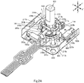
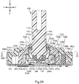
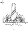
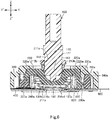
- FIG. 1 to 5B show the input device D of the first embodiment.
- Fig. 6 shows a first variant of the input device D of the first embodiment.
- Figs. 2A to 3A and 3C show a Y-Y' direction (first direction).
- the Y-Y' direction includes a Y direction (one side in the first direction) and a Y' direction (the other side in the first direction).
- Figs. 2A , 2B , and 3B to 4B show an X-X' direction (second direction).
- the X-X' direction crosses the Y-Y' direction and may be substantially orthogonal to the Y-Y' direction as shown in Figs. 2A , 2B , and 3B to 4B .
- the X-X' direction includes an X direction (one side in the second direction) and an X' direction (the other side in the second direction).
- Figs. 2A to 4B show a Z-Z' direction (third direction).
- the Z-Z' direction is substantially orthogonal to the Y-Y' and X-X' directions.
- the Z-Z' direction includes a Z direction (one side in the third direction) and a Z' direction (the other side in the third direction).
- the input device D includes a linking structure L (assembly) of an operation lever 100 and a first interlocking member 200a.
- the linking structure L includes the operation lever 100 and the first interlocking member 200a (which may be hereinafter referred to simply as an interlocking member 200a).
- the operation lever 100 is linked to the interlocking member 200a so as to be tiltable in the Y-Y' direction (in the Y and Y' directions), and is configured to tilt in the X-X' direction (in the X and X' directions) and to thereby pivot the interlocking member 200a in the same direction.
- the operation lever 100 includes a base 111 on one side in the axial direction of the operation lever 100, a first jut 120a, a second jut 120b, a first rotation shaft 130a, and a second rotation shaft 130b.
- the first jut 120a extends from the base 111 in the Y direction
- the second jut 120b extends from the base 111 in the Y' direction.
- the base 111, the first jut 120a, and the second jut 120b may preferably, but is not required to, have substantially the same width dimension.
- the first jut 120a and the second jut 120b may have substantially the same width dimension
- the base 111 may have a width dimension that is smaller than that of the first jut 120a and the second jut 120b.
- the first rotation shaft 130a is a cylinder, or alternatively a polygonal prism that approximates to a cylinder, extending in the X direction from the base 111.
- the second rotation shaft 130b is a cylinder, or alternatively a polygonal prism that approximates to a cylinder, extending in the X' direction from the base 111.
- shape A that approximates to shape B means that shape A looks like shape B when simplified with the details of shape A disregarded.
- the operation lever 100 is tiltable in the Y and Y' directions from the neutral position, with the first rotation shaft 130a and the second rotation shaft 130b serving as the pivot.
- the neutral position of the operation lever 100 may be a position where the axial direction of the operation lever 100 coincides with the Z-Z' direction (see Figs. 1 to 3B and 6 ), or may be a position where the axial direction of the operation lever 100 is at an angle to the Z-Z' direction (not shown).
- the first rotation shaft 130a may include a first portion 131a on the X'-direction side and a second portion 132a located on the X-direction side relative to the first portion 131a.
- the first portion 131a is contiguous with the base 111.
- the second portion 132a is a part or the entire part of the first rotation shaft 130a that is located on the X-direction side relative to the first portion 131a.
- the second rotation shaft 130b may include a first portion 131b on the X-direction side and a second portion 132b located on the X'-direction side relative to the first portion 131b.
- the first portion 131b is contiguous with the base 111.
- the second portion 132b is a part or the entire part of the second rotation shaft 130b that is located on the X'-direction side relative to the first portion 131b.
- the base 111, the first jut 120a, the second jut 120b, the first rotation shaft 130a, and the second rotation shaft 130b generally of such cross-shaped cross section may be collectively referred to as a cross-shaped portion of the operation lever 100.
- the base 111, the first jut 120a, the second jut 120b, the first rotation shaft 130a, and the second rotation shaft 130b generally of such X-shaped cross section may be collectively referred to as an X-shaped portion of the operation lever 100.
- the operation lever 100 may further include a swingable portion 160.
- the swingable portion 160 may be a projection being provided on and across the base 111, the first jut 120a, and the second jut 120b and projecting to the one side in the axial direction (see Figs. 3A and 3B ).
- the swingable portion 160 may be a projection being provided on the base 111 and projecting to the one side in the axial direction (see Fig. 6 ).
- the swingable portion 160 is contiguous with the base 111, the first jut 120a, and the second jut 120b.
- the swingable portion 160 is contiguous with the base 111, but with neither the first jut 120a nor the second jut 120b.
- the swingable portion 160 is swingable in the Y-Y' direction. More specifically, the swingable portion 160 is configured to swing in the Y' direction in response to the tilt of the operation lever 100 in the Y direction, and swing in the Y direction in response to the tilt of the operation lever 100 in the Y' direction.
- the swingable portion 160 has a distal face on the one side in the axial direction. This distal face may be, but is not required to be, a convex face of arc shape curving to the Z'-direction side in the cross section defined by the Y-Y' and Z-Z' directions (see Figs.
- the swingable portion 160 has a width dimension that is substantially the same, or smaller than, the width dimension of each of the first jut 120a and the second jut 120b.
- the swingable portion 160 can be omitted.
- the "first end portion” of the operation lever 100 refers to the combination of the cross-shaped portion and the swingable portion 160 of the operation lever 100, the combination the X-shaped portion and the swingable portion 160 of the operation lever 100, the cross-shaped portion of the operation lever 100 without the swingable portion 160, or the X-shaped portion of the operation lever 100 without the swingable portion 160.
- the “second end portion” of the operation lever 100 refers to the combination of the base 111, the first jut 120a, the second jut 120b, and the swingable portion 160 of the operation lever 100, or the combination of the base 111, the first jut 120a, and the second jut 120b of the operation lever 100 without the swingable portion 160. It should be appreciated that the second end portion of the operation lever 100 is a portion of the operation lever 100 that excludes the first rotation shaft 130a and the second rotation shaft 130b from the first end portion of the operation lever 100.
- the operation lever 100 may further include a core 110.
- the core 110 is generally of a rectangular prism shape extending in the axial direction of the operation lever 100, and includes a portion on the Z'-direction side, which is the base 111.
- the operation lever 100 may further include at least one ridge, namely at least one of a first ridge 141, a second ridge 142, a third ridge 143, or a fourth ridge 144 configured as follows.
- the first ridge 141 extends from the first jut 120a to the other side in the axial direction of the operation lever 100, and extends from the core 110 in the Y direction.
- the first ridge 141 is contiguous with the first jut 120a and the core 110.
- the second ridge 142 extends from the second jut 120b to the other side in the axial direction of the operation lever 100, and extends from the core 110 in the Y' direction.
- the second ridge 142 is contiguous with the second jut 120b and the core 110.
- the third ridge 143 extends from the first portion 131a of the first rotation shaft 130a, or alternatively from the first portion 131a and the second portion 132a of the first rotation shaft 130a, to the other side in the axial direction of the operation lever 100, and extends from the core 110 in the X direction.
- the third ridge 143 is contiguous with the first rotation shaft 130a and the core 110.
- the fourth ridge 144 extends from the first portion 131b of the second rotation shaft 130b, or alternatively from the first portion 131b and the second portion 132b of the second rotation shaft 130b, to the other side in the axial direction of the operation lever 100, and extends from the core 110 in the X' direction.
- the fourth ridge 144 is contiguous with the second rotation shaft 130b and the core 110.
- the at least one ridge may include at least one set of two adjacent ridges.
- the at least one set is at least one of the following sets: a set consisting of the first ridge 141 and the third ridge 143 adjacent to each other, a set consisting of the third ridge 143 and the second ridge 142 adjacent to each other, a set consisting of the second ridge 142 and the fourth ridge 144 adjacent to each other, and a set consisting of the fourth ridge 144 and the first ridge 141 adjacent to each other.
- the operation lever 100 may further include at least one reinforcing portion 150.
- the or each reinforcing portion 150 is suspended between the two adjacent ridges of the or a corresponding set, and is located on the other side in the axial direction relative to the interlocking member 200a with a clearance therebetween.
- the or each reinforcing portion 150 may be contiguous with the or a corresponding set of two adjacent ridges.
- the distance in the axial direction between the at least one reinforcing portion 150 and the interlocking member 200a is set such that, when the operation lever 100 tilts in the Y-Y' direction, the at least one reinforcing portion 150 will not abut the interlocking member 200a (for example, in the embodiment shown in Figs.
- the at least one reinforcing portion 150 will not abut a first edge 212a on the X-direction side of a first elongated hole 211a and a second edge 213a on the X'-direction side of the first elongated hole 211a of the interlocking member 200a).
- the outer face of the or each reinforcing portion 150 may be a concave or V-shaped face recessed toward the core 110, may be a flat face, or may be a convex face curving away from the core 110.
- the operation lever 100 shown in Figs. 1 to 5B is configured as follows.
- the operation lever 100 has the first ridge 141, the second ridge 142, the third ridge 143, the fourth ridge 144, and four reinforcing portions 150.
- the reinforcing portions 150 are respectively provided between the first ridge 141 and the third ridge 143 adjacent to each other, between the third ridge 143 and the second ridge 142 adjacent to each other, between the second ridge 142 and the fourth ridge 144 adjacent to each other, and between the fourth ridge 144 and the first ridge 141 adjacent to each other.
- the outer face of each reinforcing portion 150 is a concave face curving toward the core 110.
- the operation lever 100 may further include an extension 170.
- the extension 170 extends from the core 110 in the Z direction, or extends from the core 110 and the at least one ridge in the Z direction.
- the end portion on the Z-direction side of the extension 170, or alternatively a key top (not shown) provided in this end portion, may serve as a handling portion to be handled by a user.
- the extension 170 can be omitted. Where the extension 170 is omitted, the handling portion may be the core 110, the core 110 and the at least one ridge, a key top (not shown) provided at the core 110, or a key top (not shown) provided at the core 110 and the at least one ridge.
- the interlocking member 200a extends in the Y-Y' direction.
- the interlocking member 200a includes a main body 210a.
- the main body 210a includes the first elongated hole 211a, the first edge 212a on the X-direction side of the first elongated hole 211a, the second edge 213a on the X'-direction side of the first elongated hole 211a, a third edge 214a on the Y-direction side of the first elongated hole 211a, a fourth edge 215a on the Y'-direction side of the first elongated hole 211a, and a bottom 216a.
- the first elongated hole 211a is a blind hole extending in the Y-Y' direction and opening in the Z direction.
- the first edge 212a has a first inner face on the X-direction side of the first elongated hole 211a
- the second edge 213a has a second inner face on the X'-direction side of the first elongated hole 211a.
- the bottom 216a of the main body 210a closes the first elongated hole 211a on the Z'-direction side and is contiguous with the first, second, third, and fourth edges 212a, 213a, 214a, 215a.
- the bottom 216a includes a bottom face 216a1 of the first elongated hole 211a.
- the bottom face 216a1 may be, but is not required to be, a concave face of arc shape curving to the Z'-direction side in the cross section defined by the Y-Y' and Z-Z' directions (see Fig. 3B ), or faces of a semi polygonal shape that approximate to the concave face. Where the swingable portion 160 is omitted, the bottom face 216a1 may be a flat face extending in the Y-Y' and X-X' directions.
- the first elongated hole 211a houses the second end portion of the operation lever 100 (i.e., the combination of the base 111, the first jut 120a, the second jut 120b, and the swingable portion 160 of the operation lever 100, or the combination of the base 111, the first jut 120a, and the second jut 120b of the operation lever 100 without the swingable portion 160) from the Z-direction side.
- the first elongated hole 211a has a dimension in the Y-Y' direction (lengthwise dimension) that is larger than the distance in the Y-Y' direction from the end in the Y direction of the first jut 120a to the end in the Y' direction of the second jut 120b of the operation lever 100 (see Fig.
- the transverse direction of the first elongated hole 211a corresponds to the X-X' direction, but where the X-X' direction crosses the Y-Y' direction at an angle other than a right angle, the short-side direction of the first elongated hole 211a does not correspond to the X-X' direction.
- first recess 217a1 and the second recess 217a1 are omitted, the first ridge 141 and/or the second ridge 142 can also be omitted.
- the first shaft supporting arm 218a may be elastically deformable in the X direction until the first shaft supporting arm 218a is released from the abutment against the first rotation shaft 130a, and the second shaft supporting arm 218a may be elastically deformable in the X' direction until the second shaft supporting arm 218a is released from the abutment against the second rotation shaft 130b is released.
- the first rotation shaft 130a and the second rotation shaft 130b of the operation lever 100 may be rotatably supported respectively by the first shaft hole 217a and the second shaft hole 217a having the configuration (4) or (5) and may rotatably abut the first shaft supporting arm 218a and the second shaft supporting arm 218a, respectively, in the following manner.
- the second end portion of the operation lever 100 is inserted into the first elongated hole 211a from the Z-direction side, and the first rotation shaft 130a and the second rotation shaft 130b of the operation lever 100 are inserted from the Z-direction side between the first shaft supporting arm 218a and the second shaft supporting arm 218a.
- the first rotation shaft 130a and the second rotation shaft 130b of the operation lever 100 move in the Z' direction while respectively pressing the first shaft supporting arm 218a and the second shaft supporting arm 218a, and the first shaft supporting arm 218a and the second shaft supporting arm 218a elastically deform respectively in the X and X' directions.
- the first shaft supporting arm 218a and the second shaft supporting arm 218a restore themselves to respectively abut the first rotation shaft 130a and the second rotation shaft 130b from the Z-direction side, so that the first rotation shaft 130a and the second rotation shaft 130b are inserted into the first shaft hole 217a and the second shaft hole 217a, and the second end portion of the operation lever 100 is inserted, or fitted, into the first elongated hole 211a of the interlocking member 200a from the Z-direction side.
- the first shaft supporting arm 218a and the second shaft supporting arm 218a may not be configured to elastically deform as described above.
- the shaft When assembling the operation lever 100 to the first interlocking member 200a, after the second end portion of the operation lever 100 is inserted, or fitted, into the first elongated hole 211a, the shaft may be inserted into the first shaft hole 217a, the fixing hole, and the second shaft hole 217a and held by the base 111.
- the first elongated hole 211a, the first shaft hole 217a, and the second shaft hole 217a in any of the above aspects collectively, form a recess generally of a cross shape in the cross section defined by the Y-Y' and X-X' directions (see Fig. 3C ).
- the first elongated hole 211a, the first shaft hole 217a, and the second shaft hole 217a generally of such cross-shaped cross section may be collectively referred to as a cross-shaped recess of the interlocking member 200a.
- the cross-shaped portion of the operation lever 100 without the swingable portion 160, or alternatively the cross-shaped portion and the swingable portion 160 of the operation lever 100.
- the first elongated hole 211a, the first shaft hole 217a, and the second shaft hole 217a in any of the above aspects collectively, form a recess generally of an X shape in the cross section defined by the Y-Y' and X-X' directions (not shown).
- the first elongated hole 211a, the first shaft hole 217a, and the second shaft hole 217a generally of such X-shaped cross section may be collectively referred to as an X-shaped recess of the interlocking member 200a.
- received or fitted in the X-shaped recess of the interlocking member 200a is the X-shaped portion of the operation lever 100 without the swingable portion 160, or alternatively the X-shaped portion and the swingable portion 160 of the operation lever 100.
- the interlocking member 200a may further includes a pair of pivot shafts 220a extending from the main body 210a in the Y and Y' directions, respectively.
- Each pivot shaft 220a is a cylinder, or alternatively a polygonal prism that approximates to a cylinder.
- one of the pivot shafts 220a is a cylinder, or alternatively a polygonal prism that approximates to a cylinder, that extends from the main body 210a in the Y direction
- the other pivot shaft 220a is a cylinder, or alternatively a polygonal prism that approximates to a cylinder, that extends from the main body 210a in the Y' direction.
- the main body 210a of the interlocking member 200a is pivotable in the X-X' direction from its initial position, with the pair of pivot shafts 220a serving as the pivot.
- the first end portion of the operation lever 100 is received or fitted in the cross-shaped or X-shaped recess of the main body 210a.
- this causes the operation lever 100 to tilt from the neutral position in the X direction.
- the main body 210a pivots from the initial position in the X' direction with the pivot shafts 220a serving as the pivot, this causes the operation lever 100 to tilt from the neutral position in the X' direction.
- the operation lever 100 is configured to tilt in the X and X' directions with the pivot shafts 220a serving as the pivot
- the interlocking member 200a is configured to accordingly pivot in the X or X' direction with the pivot shafts 220a serving as the pivot.
- the initial position of the main body 210a may be the position at which the main body 210a is located with the operation lever 100 located at the neutral position.
- the operation lever 100 may be configured to be tiltable from the neutral position in a first oblique direction, a second oblique direction, a third oblique direction, and/or a fourth oblique direction.
- the first oblique direction is a direction including components of the Y and X directions.
- the second oblique direction is a direction including components of the Y and X' directions.
- the third oblique direction is a direction including components of the Y' and X directions.
- the fourth direction is a direction including components of the Y' and X' directions.
- the operation lever 100 tilts from the neutral position in the first oblique direction
- the operation lever 100 tilts in the Y direction with the first rotation shaft 130a and the second rotation shaft 130b serving as the pivot
- tilts in the X direction with the pivot shafts 220a of the interlocking member 200a serving as the pivot
- the main body 210a of the interlocking member 200a pivots from the initial position in the X direction.
- the operation lever 100 tilts from the neutral position in the second oblique direction
- the operation lever 100 tilts in the Y direction with the first rotation shaft 130a and the second rotation shaft 130b serving as the pivot
- the main body 210a of the interlocking member 200a pivots from the initial position in the X' direction.
- the operation lever 100 tilts from the neutral position in the third oblique direction
- the operation lever 100 tilts in the Y' direction with the first rotation shaft 130a and the second rotation shaft 130b serving as the pivot
- the main body 210a of the interlocking member 200a pivots from the initial position in the X direction.
- the operation lever 100 tilts from the neutral position in the fourth oblique direction
- the operation lever 100 tilts in the Y' direction with the first rotation shaft 130a and the second rotation shaft 130b serving as the pivot
- the main body 210a of the interlocking member 200a pivots from the initial position in the X' direction.
- the Y direction, the first oblique direction, or the second oblique direction may be referred to as a direction including a component of the Y direction;
- the Y' direction, the third oblique direction, or the fourth oblique direction may be referred to as a direction including a component of the Y' direction;
- the X direction, the first oblique direction, or the third oblique direction may be referred to as a direction including a component of the X direction;
- the X' direction, the second oblique direction, or the fourth oblique direction may be referred to as a direction including a component of the X' direction.
- the linking structure L of any of the above aspects may further include a second interlocking member 200b (which may be hereinafter referred to simply as an interlocking member 200b).
- the interlocking member 200b extends in the X-X' direction.
- the interlocking member 200b intersects the first interlocking member on the Z-direction side relative to the first interlocking member 200a.
- the interlocking member 200b includes a main body 210b.
- the main body 210b includes a second elongated hole 211b, a first edge 212b on the Y-direction side of the second elongated hole 211b, a second edge 213b on the Y'-direction side of the second elongated hole 211b, a third edge 214b on the X-direction side of the second elongated hole 211b, and a fourth edge 215b on the X'-direction side of the second elongated hole 211b.
- the second elongated hole 211b is a through hole formed through the main body 210b in the Z-Z' direction and extends in the X-X' direction.
- the operation lever 100 of any of the above aspects passes through the second elongated hole 211b such as to be tiltable in the X-X' direction inside the second elongated hole 211b.
- the operation lever 100 may slidably abut the first edge 212b of the second elongated hole 211b and the second edge 213b of the second elongated hole 211b.
- the operation lever 100 may be opposed with a narrow interstice to, and abuttable against, the first edge 212b of the second elongated hole 211b and the second edge 213b of the second elongated hole 211b.
- the first ridge 141 and the second ridge 142 of the operation lever 100 may slidably abut the first edge 212b and the second edge 213b, respectively (see Figs. 1 to 6 ), or may be opposed with a narrow interstice to, and abuttable against, the first edge 212b and the second edge 213b.
- the core 110 of the operation lever 100 may slidably abut the first edge 212b, or may be opposed with a narrow interstice to, and abuttable against, the first edge 212b.
- the core 110 of the operation lever 100 may slidably abut the second edge 213b, or may be opposed with a narrow interstice to, and abuttable against, the second edge 213b.
- the main body 210b may further include a first guide 216b and a second guide 216b.
- the first guide 216b is provided on the third edge 214b of the second elongated hole 211b, and is located on a first oblique-direction side, or on the X-direction side, relative to the first shaft supporting arm 218a.
- the first oblique direction includes components of the X and Z directions.
- the first guide 216b is a wall of the third edge 214b and covers the first shaft supporting arm 218a from the oblique-direction side or the X-direction side.
- the face on the X'-direction side of the first guide 216b is provided with a recess generally of arc shape extending in the Y-Y' direction and being recessed in the Z direction (see Figs. 3A and 4B ), or alternatively a ridge generally of arc shape extending in the Y-Y' direction and projecting in the Z direction.
- the recess or the ridge serves to guide the first shaft supporting arm 218a such as to be swingable in the Y-Y' direction.
- the first guide 216b guides the first shaft supporting arm 218a from the oblique-direction side or the X-direction side so as to suppress elastic deformation of the first shaft supporting arm 218a in the X direction.
- the second guide 216b is provided on the fourth edge 215b of the second elongated hole 211b, and is located on a second oblique-direction side, or alternatively on the X'-direction side, relative to the second shaft supporting arm 218a.
- the second oblique direction includes components of the X' and Z directions.
- the second guide 216b is a wall of the fourth edge 215b and covers the second shaft supporting arm 218a from the oblique-direction side or the X'-direction side.
- the face on the X-direction side of the second guide 216b is provided with a recess generally of arc shape extending in the Y-Y' direction and being recessed in the Z direction (see Figs. 3A and 4B ), or alternatively a ridge generally of arc shape extending in the Y-Y' direction and projecting in the Z direction.
- the recess or the ridge serves to guide the second shaft supporting arm 218a such as to be swingable in the Y-Y' direction.
- the second guide 216b guides the second shaft supporting arm 218a from the oblique-direction side or the X'-direction side so as to suppress elastic deformation of the second shaft supporting arm 218a in the X' direction.
- the first guide 216b and the second guide 216b can be omitted.
- the main body 210b may include a first retaining portion and a second retaining portion (not shown).
- the first retaining portion is provided on the third edge 214b, abuts the first rotation shaft 130a from the Z-direction side, and supports the first rotation shaft 130a in a rotatable manner.
- the second retaining portion is provided on the fourth edge 215b, abuts the second rotation shaft 130b from the Z-direction side, and supports the second rotation shaft 130b in a rotatable manner.
- the first retaining portion and the second retaining portion can be omitted.
- the third edge 214b of the second elongated hole 211b may include a first protrusion 217b protruding toward the gap between the first ridge 141 and the third ridge 143, and a second protrusion 217b protruding toward the gap between the third ridge 143 and the second ridge 142; and the fourth edge 215b of the second elongated hole 211b may include a third protrusion 217b protruding toward the gap between the second ridge 142 and the fourth ridge 144, and a fourth protrusion 217b protruding toward the gap between the fourth ridge 144 and the first ridge 141.
- the amount of protrusion of the first protrusion 217b may be set such that the operation lever 100 will abut neither the first ridge 141 nor the third ridge 143 when the operation lever 100 tilts in a direction including the component of the Y direction and/or the component of the X direction.
- the amount of protrusion of the first protrusion 217b may be set such that the operation lever 100 will not abut the reinforcing portion 150 when the operation lever 100 tilts in a direction including the component of the Y direction and/or the component of the X direction.
- the amount of protrusion of the second protrusion 217b may be set such that the operation lever 100 will abut neither the third ridge 143 nor the second ridge 142 when the operation lever 100 tilts in a direction including the component of the Y' direction and/or the component of the X direction.
- the amount of protrusion of the second protrusion 217b may be set such that the operation lever 100 will not abut the reinforcing portion 150 when the operation lever 100 tilts in a direction including the component of the Y' direction and/or the component of the X direction.
- the amount of protrusion of the third protrusion 217b may be set such that the operation lever 100 will abut neither the second ridge 142 nor the fourth ridge 144 when the operation lever 100 tilts in a direction including the component of the Y' direction and/or the component of the X' direction.
- the amount of protrusion of the third protrusion 217b may be set such that the operation lever 100 will not abut the reinforcing portion 150 when the operation lever 100 tilts in a direction including the component of the Y' direction and/or the component of the X' direction.
- the amount of protrusion of the fourth protrusion 217b may be set such that the operation lever 100 will abut neither the fourth ridge 144 nor the first ridge 141 when the operation lever 100 tilts in a direction including the component of the Y direction and/or the component of the X' direction.
- the amount of protrusion of the fourth protrusion 217b may be set such that the operation lever 100 will not abut the reinforcing portion 150 when the operation lever 100 tilts in a direction including the component of the Y direction and/or the component of the X' direction.
- the provision of the first to fourth protrusions 217b improves the strength of the main body 210b of the interlocking member 200b. Any of the first to fourth protrusions 217b can be omitted.
- the interlocking member 200b further includes a pair of pivot shafts 220b extending from the main body 210b in the X and X' direction, respectively.
- Each pivot shaft 220b is a cylinder, or alternatively a polygonal prism that approximates to a cylinder.
- one of the pivot shafts 220b is a cylinder, or alternatively a polygonal prism that approximates to a cylinder, that extends from the main body 210b in the X direction
- the other pivot shaft 220b is a cylinder, or alternatively a polygonal prism that approximates to a cylinder, that extends from the main body 210b in the X' direction.
- the interlocking member 200b is pivotable in the Y-Y' direction with the pivot shafts 220b serving as the pivot.
- the operation lever 100 tilts from the neutral position in a direction including the component of the Y direction with the first rotation shaft 130a and the second rotation shaft 130b serving as the pivot, the operation lever 100 presses the first edge 212b of the main body 210b of the interlocking member 200b in the Y direction, so that the main body 210b pivots from the initial position in the Y direction.
- the operation lever 100 tilts from the neutral position in a direction including the component of the Y' direction with the first rotation shaft 130a and the second rotation shaft 130b serving as the pivot, the operation lever 100 presses the second edge 213b of the main body 210b of the interlocking member 200b in the Y' direction, so that the main body 210b pivots from the initial position in the Y' direction.
- the initial position of the main body 210b may be the position at which the main body 210b is located with the operation lever 100 located at the neutral position.
- the input device D may further include a housing 300.
- the housing 300 may have either of the following configurations (a) or (b).
- the interlocking member 200a may further include at least one pivotable portion 230a extending in the Z' direction from at least one of the pivot shafts 220a.
- the at least one pivotable portion 230a is configured to pivot from its initial position in the X' direction in accordance with the tilt of the operation lever 100 in a direction including the component of the X direction and the rotation of the pivot shafts 220a in the X direction.
- the at least one pivotable portion 230a is also configured to pivot from its initial position in the X direction in accordance with the tilt of the operation lever 100 in a direction including the component of the X' direction and the rotation of the pivot shafts 220a in the X' direction.
- the initial position of the pivotable portion 230a may be the position at which the pivotable portion 230a is located with the operation lever 100 located at the neutral position.
- the interlocking member 200b may further include at least one pivotable portion 230b extending in the Z' direction from at least one of the pivot shafts 220b.
- the at least one pivotable portion 230b is configured to pivot from its initial position in the Y' direction in accordance with the tilt of the operation lever 100 in a direction including the component of the Y direction and the rotation of the pivot shafts 220b in the Y direction.
- the at least one pivotable portion 230b is also configured to pivot from its initial position in the Y direction in accordance with the tilt of the operation lever 100 in a direction including the component of the Y' direction and the rotation of the pivot shafts 220b in the Y' direction.
- the initial position of the pivotable portion 230b may be the position at which the pivotable portion 230b is located with the operation lever 100 located at the neutral position.
- the housing 300 may further have at least one accommodating hole 330a and at least one accommodating hole 330b.
- the at least one accommodating hole 330a is provided on an outer side (on the Y-direction side in Figs. 3B and 4B ) relative to at least one of the first supports 320a, and accommodates the at least one pivotable portion 230a.
- the at least one accommodating hole 330b is provided on an outer side (on the X'-direction side in Figs. 3A and 4B ) relative to at least one of the second supports 320b, and accommodates the at least one pivotable portion 230b.
- the at least one pivotable portion 230a and the at least one pivotable portion 230b may be accommodated in the accommodating portion 310 of the housing 300 from the Z'-direction side.
- the input device D may further include a frame 400, a circuit board 600, a slider 700a, and a slider 700b.
- the circuit board 600 is arranged on the Z'-direction side relative to the housing 300.
- the frame 400 is attached to the housing 300 from the Z'-direction side.
- the circuit board 600 is held between the housing 300 and the frame 400. Where the circuit board 600 is fixed to the housing 300, the frame 400 can be omitted.
- the slider 700a is engaged with the at least one pivotable portion 230a of the interlocking member 200a.
- one of the slider 700a or the at least one pivotable portion 230a is provided with an engaging protrusion, and the other is provided with an engaging recess to receive the engaging protrusion.
- the at least one pivotable portion 230a pivots in the X' or X direction to press the slider 700a in the X' or X direction, this causes the slider 700a to slide from its initial position in the same direction on and along the circuit board 600.
- the initial position of the slider 700a may be the position at which the slider 700a is located with the pivotable portion 230a located at its initial position.
- the slider 700b is engaged with the at least one pivotable portion 230b of the interlocking member 200b.
- the at least one pivotable portion 230b pivots in the Y' or Y direction to press the slider 700b in the Y' or Y direction, this causes the slider 700b to slide from its initial position in the same direction on and along the circuit board 600.
- the initial position of the slider 700b may be the position at which the slider 700b is located with the pivotable portion 230b located at its initial position.
- the housing 300 may further includes a movement channel 340a and a movement channel 340b.
- the movement channel 340a accommodates the slider 700a such as to be movable in the X-X' direction.
- the movement channel 340b accommodates the slider 700b such as to be movable in the Y-Y' direction.
- the input device D may further include a detector 500a (second detector) and a detector 500b (first detector).
- the detector 500a is configured to detect the tilt of the operation lever 100 in a direction including the component of the X direction and the tilt of the operation lever 100 in a direction including the component of the X' direction, and to change a signal from the detector 500a in response to the amount of the tilt or output a signal from the detector 500a based on the tilt.
- the detector 500b is configured to detect the tilt of the operation lever 100 in a direction including the component of the Y direction and the tilt of the operation lever 100 in a direction including the component of the Y' direction, and to change a signal from the detector 500b in response to the amount of the tilt or output a signal from the detector 500b based on the tilt.
- the detectors 500a and 500b may be variable resistors.
- the detector 500a includes a wiper 510a which is electrically conductive, a resistor 520a, and a conductor 530a
- the detector 500b includes a wiper 510b which is electrically conductive, a resistor 520b, and a conductor 530b.
- the resistor 520a and the conductor 530a of the detector 500a are formed on an end portion on the Y-direction side of the circuit board 600.
- the wiper 510a of the detector 500a is accommodated in an accommodation recess of the slider 700a and fixed to the ceiling (the face on the Z-direction side) of the accommodation recess.
- the wiper 510a is in contact with the resistor 520a and the conductor 530a to establish electrical conduction between the resistor 520a and the conductor 530a.
- the wiper 510a is slidable on and along the resistor 520a and the conductor 530a in accordance with the movement of the slider 700a in the X' or X direction.
- the sliding of the wiper 510a on the resistor 520a and the conductor 530a changes a resistance value of the detector 500a (a signal from the detector 500a).
- This change in resistance value is inputted via the circuit board 600 into a control part of an electronic device that is mounted with the input device D, and the control part detects that the operation lever 100 has tilted in a direction including the component of the X or X' direction and also detects the amount of the tilt.
- the resistor 520b and the conductor 530b of the detector 500b are formed on an end portion on the X'-direction side of the circuit board 600.
- the wiper 510b of the detector 500b is accommodated in an accommodation recess of the slider 700b and fixed to the ceiling (the face on the Z-direction side) of the accommodation recess.
- the wiper 510b is in contact with the resistor 520b and the conductor 530b to establish electrical conduction between the resistor 520b and the conductor 530b.
- the wiper 510b is slidable on and along the resistor 520b and the conductor 530b in accordance with the movement of the slider 700b in the Y' or Y direction.
- the sliding of the wiper 510b on the resistor 520b and the conductor 530b changes a resistance value of the detector 500b (a signal from the detector 500b).
- This change in resistance value is inputted via the circuit board 600 into the control part of the electronic device, and the control part detects that the operation lever 100 has tilted in a direction including the component of the Y or Y' direction and also detects the amount of the tilt.
- the detectors 500a and 500b are not limited to variable resistors.
- the detectors 500a and 500b may alternatively be constituted by, for example, electrostatic sensors, magnetic sensors, optical sensors, switches, or the like.
- the electrostatic sensor of the detector 500a may be configured to change a signal in accordance with a change in capacitance caused by a movement in the X-X' direction of a conductor, which may be provided in the at least one pivotable portion 230a or the slider 700a.
- the electrostatic sensor of the detector 500b may be configured to change a signal in accordance with a change in capacitance caused by a movement in the Y-Y' direction of a conductor, which may be provided in the at least one pivotable portion 230b or the slider 700b.
- the magnetic sensor of the detector 500a may be configured to change a signal in accordance with a change in magnetic flux density caused by a movement in the X-X' direction of a magnetic body, which may be provided in the at least one pivotable portion 230a and or the slider 700a.
- the magnetic sensor of the detector 500b may be configured to change a signal in accordance with a change in magnetic flux density caused by a movement in the Y-Y' direction of a magnetic body, which may be provided in the at least one pivotable portion 230b and or the slider 700b.
- the optical sensor of the detector 500a may be configured to optically detect a plurality of rotation angles in the X-X' direction of the at least one pivotable portion 230a or detect a plurality of positions to which the slider 700a has moved, and then output a signal corresponding to the detection.
- the optical sensor of the detector 500b may be configured to optically detect a plurality of rotation angles in the Y-Y' direction of the at least one pivotable portion 230b or detect a plurality of positions to which the slider 700b has moved, and then output a signal corresponding to the detection.
- the switch of the detector 500a may be configured to be electrically or mechanically turned on, in response to the pivoting of the at least one pivotable portion 230a or in response to the movement in the X-X' direction of the slider 700a.
- the switch of the detector 500b may be configured to be electrically or mechanically turned on, in response to the pivoting of the at least one pivotable portion 230ba or in response to the movement in the Y-Y' direction of the slider 700b.
- the electrostatic sensor, the magnetic sensor, the optical sensor, or the switch of the detector 500a is configured to change or output a signal in accordance with the pivoting of the at least one pivotable portion 230a or in accordance with the movement of the slider 700a
- the electrostatic sensor, the magnetic sensor, the optical sensor, or the switch of the detector 500b is configured to change or output a signal in accordance with the pivoting of the at least one pivotable portion 230b or in accordance with the movement of the slider 700b.
- the electrostatic sensors, the magnetic sensors, the optical sensors, or the switches are configured to change or output signals in accordance with the pivoting of the at least one pivotable portion 230a and the at least one pivotable portion 230b, it is possible to omit the sliders 700a and 700b and the movement channels 340a and 340b of the housing 300.
- the control part of the electronic device may have one of the following configurations (i) to (iii): (i) The control part is configured to receive signals from the electrostatic sensors or the magnetic sensors and, based on the changes of the received signals, detect that the operation lever 100 has tilted in a direction (i.e. a direction including the component of the X direction, a direction including the component of the X' direction, a direction including the component of the Y direction, or a direction including the component of the Y' direction) and also detect the amount of the tilt.
- a direction i.e. a direction including the component of the X direction, a direction including the component of the X' direction, a direction including the component of the Y direction, or a direction including the component of the Y' direction
- the control part is configured to receive signals outputted by the optical sensors and, based on the received signals, detect that the operation lever 100 has tilted in a direction (i.e., a direction including the component of the X direction, a direction including the component of the X' direction, a direction including the component of the Y direction, or a direction including the component of the Y' direction) and also detect the amount of the tilt.
- a direction i.e., a direction including the component of the X direction, a direction including the component of the X' direction, a direction including the component of the Y direction, or a direction including the component of the Y' direction
- the control part is configured to detect, based on which of the switches are turned on, that the operation lever 100 has tilted in a direction (i.e., a direction including the component of the X direction, a direction including the component of the X' direction, a direction including the component of the Y direction, or a direction including the component of the Y' direction).
- the input device D may further include a restoration mechanism 800 for restoring the operation lever 100 in a tilted state to its neutral position.
- the interlocking member 200a may further include at least one abutment face 240a
- the interlocking member 200b may further include at least one abutment face 240b.
- the at least one abutment face 240a is at least one face on the Z'-direction side of the main body 210a and the pivot shafts 220a. With the operation lever 100 located at the neutral position, the at least one abutment face 240a is substantially parallel to the circuit board 600.
- the at least one abutment face 240b is at least one face on the Z'-direction side of the main body 210b and the pivot shafts 220b. With the operation lever 100 located at the neutral position, the at least one abutment face 240b is located at the same height in the Z-Z' direction as the at least one abutment face 240a, and is substantially parallel to the circuit board 600.
- the restoration mechanism 800 may include a ring 810 and urging member 820.
- the ring 810 is a generally circular ring plate and abuts the at least one abutment face 240a of the interlocking member 200a and the at least one abutment face 240b of the interlocking member 200b.
- the urging member 820 is an elastic body, such as a coil spring or a rubber member, and is arranged between the circuit board 600 and the ring 810.
- the urging member 820 is configured to keep the at least one abutment face 240a and the at least one abutment face 240b substantially in parallel to the circuit board 600 by urging the abutment faces 240a and 240b via the ring 810. This makes it possible to keep the main body 210a, the pair of pivot shafts 220a of the interlocking member 200a, and the at least one pivotable portion 230a in their initial positions, and keep the main body 210b, the pair of pivot shafts 220b, and the at least one pivotable portion 230b of the interlocking member 200b in their initial positions.
- the operation lever 100 is abutted by the first edge 212a and the second edge 213a of the first elongated hole 211a of the interlocking member 200a and by the first edge 212b and the second edge 213b of the second elongated hole 211b of the interlocking member 200b, so that the operation lever 100 is kept at the neutral position.
- the urging member 820 may have a shape in which the end face on the Z-direction side is inclined.
- the urging member 820 may be configured to urge the at least one abutment face 240a and at least one abutment face 240b via the ring 810 so as to keep the abutment faces in an inclined state relative to the circuit board 600.
- the at least one abutment face 240a and/or the at least one abutment face 240b becomes inclined and the ring 810 becomes inclined so as to compress the urging member 820.
- the urging member 820 restores itself to restore, via the ring810, the at least one abutment face 240a and/or the at least one abutment face 240b to the state (initial state) of being substantially parallel or inclined relative to the circuit board 600.
- the main body 210a, the pair of pivot shafts 220a, and the at least one pivotable portion 230a of the interlocking member 200a return to their initial positions, and/or the main body 210b, the pair of pivot shafts 220b, and the at least one pivotable portion 230b of the interlocking member 200b return to their initial positions, so that the operation lever 100 returns to the neutral position.
- the ring 810 can be omitted. Where the ring 810 is omitted, the urging member 820 may be in direct abutment against the at least one abutment face 240a and the at least one abutment face 240b.
- the linking structure L of the operation lever 100 and the input device D including the linking structure L as described above provide at least the following technical features and effects.
- the linking structure L of the operation lever 100 imparts improved strength to the operation lever 100 being twisted in the circumferential direction for the following reasons.
- the cross-shaped portion of the operation lever 100 is received or fitted in the cross-shaped recess of the interlocking member 200a, or alternatively the X-shaped portion of the operation lever 100 is received or fitted in the X-shaped recess of the interlocking member 200a. This arrangement improves the strength of the operation lever 100 being twisted in the circumferential direction.
- the first elongated hole 211a of the interlocking member 200a is a blind hole which is closed on the Z'-direction side by the bottom 216a, and the bottom 216a is contiguous with the first edge 212a, the second edge 213a, the third edge 214a, and the fourth edge 215a of the first elongated hole 211a.
- swingable portion 160 in addition to the cross-shaped portion of the operation lever 100 are received or fitted in the cross-shaped recess of the interlocking member 200a, or where the swingable portion 160 in addition to X-shaped portion of the operation lever 100 are received or fitted in the X-shaped recess of the interlocking member 200a, either of these arrangements imparts an improved strength to the operation lever 100 being twisted in the circumferential direction.
- the first jut 120a and the second jut 120b have improved twisting strength of in the circumferential direction.
- first ridge 141 is contiguous with the first jut 120a and the core 110
- first jut 120a has improved twisting strength in the circumferential direction
- second ridge 142 is contiguous with the second jut 120b and the core 110
- second jut 120b has improved twisting strength in the circumferential direction
- third ridge 143 is contiguous with the first rotation shaft 130a and the core 110
- first rotation shaft 130a has improved twisting strength in the circumferential direction.
- fourth ridge 144 is contiguous with the second rotation shaft 130b and the core 110
- the second rotation shaft 130b has improved twisting strength in the circumferential direction.
- the two ridges have improved twisting strength. This results in that at least two of the first jut 120a, the second jut 120b, the first rotation shaft 130a, and the second rotation shaft 130b, which are contiguous with the two ridges, have improved twisting strength in the circumferential direction.
- the main body 210b of the interlocking member 200b has the first to fourth protrusions 217b
- the main body 210b has improved strength, resulting in that the interlocking member 200b has improved twisting strength in the circumferential direction.
- first guide 216b and the second guide 216b of the interlocking member 200b cover and guide the first shaft supporting arm 218a and the second shaft supporting arm 218a in any of the manners described above, even when the above-mentioned load in the Z direction is applied to the first shaft supporting arm 218a and the second shaft supporting arm 218a, the first guide 216b and the second guide 216b serve to suppress elastic deformation of the first shaft supporting arm 218a and the second shaft supporting arm 218a in the X and X' directions.
- the load from the second rotation shaft 130b of the operation lever 100 is applied not only to the second shaft supporting arm 218a but also to the second guide 216b, in other words, the load is distributed between the second shaft supporting arm 218a and the second guide 216b.
- the above-mentioned input device D provide the following technical features and effects.
- the cross-shaped portion of the operation lever 100 is received or fitted in the close-bottomed cross-shaped recess of the interlocking member 200a, or alternatively the X-shaped portion of the operation lever 100 is received or fitted in the close-bottomed X-shaped recess of the interlocking member 200a.
- This arrangement makes is possible to reduce the external dimensions of the first rotation shaft 130a and the second rotation shaft 130b of the operation lever 100, and thus possible to reduce the dimension in the Z-Z' direction of the input device D.
- first rotation shaft 130a and the second rotation shaft 130b of the operation lever 100 are rotatably supported from the Z-direction side by the first shaft supporting arm 218a and the second shaft supporting arm 218a of the interlocking member 200a in any of the manners described above, the load applied from the first rotation shaft 130a of the operation lever 100 is distributed between the first shaft supporting arm 218a and the first guide 216b, and the load applied from the second rotation shaft 130b of the operation lever 100 is distributed between the second shaft supporting arm 218a and the second guide 216b, this arrangement makes it possible to reduce the dimensions in the Z-Z' direction of the first shaft supporting arm 218a and the second shaft supporting arm 218a, and reduce the dimensions in the Z-Z' direction of the first guide 216b and the second guide 216b. This results in a reduced dimension in the Z-Z' direction of the input device D.
- the interlocking member 200a has improved twisting strength in the circumferential direction.
- the interlocking member 200b has improved twisting strength in the circumferential direction. Improved twisting strength in the circumferential direction of the interlocking member 200a and the interlocking member 200b results in improved twisting strength in the circumferential direction of the input device D.
- the linking structure of the operating lever and the input device of the invention are not limited to the embodiments described above, but may be modified as appropriate within the scope of the claims. Some examples of modification are described below.
- the second interlocking member of the invention can be omitted. Where the second interlocking member of the invention is omitted, it is preferable to additionally omit the components associated with the second interlocking member, such as the second supports and the sliders. It is also preferable to modify the detectors 500a and 500b such that they are configured to directly detect the tilt of the operation lever 100.
- the detectors 500a and 500b may be constituted by electrostatic sensors, magnetic sensors, or the like.
- the electrostatic sensor of the detector 500a may be configured to change a signal in accordance with a change in capacitance caused by movement of a conductor provided in the base 111 or the swingable portion 160 of the operation lever 100 in a direction including the component of the X or X' direction
- the electrostatic sensor of the detector 500b may be configured to change a signal in accordance with a change in capacitance caused by movement of the conductor in a direction including the component of the Y or Y' direction.
- the magnetic sensor of the detector 500a may be configured to change a signal in accordance with a change in magnetic flux density caused by movement of the magnetic material provided in the base 111 or the swingable portion 160 of the operation lever 100 in a direction including the component of the X or X' direction, while the magnetic sensor of the detector 500b may be configured to change a signal in accordance with a change in magnetic flux density caused by movement of the magnetic material in a direction including the component of the Y or Y' direction.
- the linking structure of the operation lever of the invention may include a cover in place of the second interlocking member of any of the above aspects.
- This cover may have the same configuration as the main body of the second interlocking member of any of the above aspects.
- This cover may include, for example, the second elongated hole, the first edge on the one side in the first direction of the second elongated hole, the second edge on the other side in the first direction of the second elongated hole, the third edge on the one side in the second direction of the second elongated hole, and the fourth edge on the other side in the second direction of the second elongated hole of any of the above aspects.
- the cover may further include the first guide and the second guide of any of the above aspects.
- the cover may be fixed to the housing, the circuit board, the frame, and/or other component of the input device.
- the operation lever of the invention may be configured to be tiltable only in the X-X' and Y-Y' directions, and none of oblique directions.
- the opening on the Z-direction side of the accommodating portion 310 of the housing 300 may be formed in a generally cross- or X-shape extending in the X-X' and Y-Y' directions to guide the operation lever.
- the first direction of the invention may be any direction that coincides with the longitudinal direction of the first elongated hole of the first interlocking member of the invention.
- the second direction of the invention may be any direction that crosses the first direction.
- the third direction of the invention may be any direction that is substantially orthogonal to the first and second directions.
Landscapes
- Physics & Mathematics (AREA)
- General Physics & Mathematics (AREA)
- Engineering & Computer Science (AREA)
- Automation & Control Theory (AREA)
- Mechanical Control Devices (AREA)
- Switches With Compound Operations (AREA)
Abstract
Description
- The invention relates to linking structures for operation levers and also relates to input devices including the linking structures.
- Japanese Unexamined Patent Application Publication No.
2004-164423 - The main body of the first interlocking member has a low rigidity because it is provided with the first elongated hole, which is a through hole, and has a generally frame-like shape in plan view. When the operation lever is twisted in a circumferential direction, one of the first and second bulging portions of the operation lever presses, from the other side in the second direction, a first edge on one side in the second direction of the first elongated hole of the main body of the first interlocking member, and the other one of the first the second bulging portions presses, from the one side in the second direction, a second edge on the other side in the second direction of the first elongated hole of the main body of the first interlocking member, which may result in distortion of the main body of the first interlocking member. Therefore, the conventional input device has a low strength to the twisting of the operation lever in the circumferential direction.
- The invention provides a linking structure of an operation lever improving the strength of the operation lever being twisted in a circumferential direction. The invention also provides an input device including the linking structure.
- The linking structure of an operation lever according to an aspect of the invention includes a first interlocking member and an operation lever.
- The first interlocking member extends in a first direction and is pivotable in a second direction crossing the first direction. The first interlocking member includes a first elongated hole, a first edge of the first elongated hole on one side in the second direction, a second edge of the first elongated hole on the other side in the second direction, a third edge of the first elongated hole on one side in the first direction, a fourth edge of the first elongated hole on the other side in the first direction, a bottom, a first shaft hole, and a second shaft hole. The first elongated hole is a blind hole extending in the first direction and opening to one side in a third direction. The third direction is substantially orthogonal to the first and second directions. The bottom of the first interlocking member closes the first elongated hole on the other side in the third direction and is contiguous with the first, second, third, and fourth edges. The first shaft hole is provided in the first edge, extends from the first elongated hole to the one side in the second direction, and communicates with the first elongated hole. The second shaft hole is provided in the second edge, extends from the first elongated hole to the other side in the second direction, and communicates with the first elongated hole.
- The operation lever is linked to the first interlocking member such as to be tiltable in the first direction, and is configured to tilt in the second direction and to thereby pivot the first interlocking member to the same direction as the tilt of the operation lever. The operation lever includes a base provided on one side in an axial direction of the operation lever, a first jut, a second jut, a first rotation shaft, and a second rotation shaft. The base is received in the first elongated hole. The first jut extends from the base to the one side in the first direction. The second jut extends from the base to the other side in the first direction. The first and second juts are swingably received in the first elongated hole. The first and second juts are in abutment with, or alternatively opposed with a narrow clearance to, the first and second edges. The first rotation shaft extends from the base to the one side in the second direction and is supported in the first shaft hole such as to be rotatable in the first direction. The second rotation shaft extends from the base to the other side in the second direction and is supported in the second shaft hole such as to be rotatable in the first direction.
- The linking structure of this aspect imparts improved strength to the operation lever being twisted in the circumferential direction for the following reason. Since the first elongated hole of the first interlocking member is a blind hole closed on the other side in the third direction with the bottom contiguous with the first, second, third, and fourth edges, the first interlocking member will resist distortion when the operation lever is twisted in the circumferential direction such that the first jut presses one of the first and second edges of the first elongated hole of the first interlocking member, and such that the second jut presses the other of the first and second edges.
- The base may be in abutment with, or alternatively being opposed with a narrow clearance to, the first and second edges.
- The bottom of the first interlocking member may include a bottom face of the first elongated hole. In this case, the operation lever may further include a swingable portion. The swingable portion may be provided on the base and project to the one side in the axial direction, or alternatively may be provided on the base, the first jut, and the second jut and project to the one side in the axial direction. In either case, the swingable portion may be swingably received in the first elongated hole and may slidably abut the bottom face of the first elongated hole. The swingable portion may be in abutment with, or opposed with a narrow clearance to, the first and second edges.
- The first shaft hole of the first interlocking member may include a first recess. The first recess may be provided in the first edge, extend from the first elongated hole to the one side in the second direction, communicate with the first elongated hole, and open to the one side in the third direction. The second shaft hole of the first interlocking member may include a second recess. The second recess may be provided in the second edge, extend from the first elongated hole to the other side in the second direction, communicate with the first elongated hole, and open to the one side in the third direction.
- The first rotation shaft may include a first portion on the other side in the second direction and a second portion on the one side in the second-direction side relative to the first portion of the first rotation shaft. The first portion, or the first portion and the second portion, of the first rotation shaft may be rotatably supported in the first recess. The second rotation shaft may include a first portion on the one side in the second direction and a second portion on the other side in the second-direction side relative to the first portion of the second rotation shaft. The first portion of the second rotation shaft, or the first portion and the second portion, of the second rotation shaft may be rotatably supported in the second recess.
- The operation lever may further include a core. The core may extend in the axial direction of the operation lever and include the base.
- The operation lever may further include at least one ridge. The at least one ridge may include at least one of a first ridge, a second ridge, a third ridge, or a fourth ridge. The first ridge may extend from the first jut to the other side in the axial direction and may also extend from the core to the one side in the first direction. The second ridge may extend from the second jut to the other side in the axial direction and may also extend from the core to the other side in the first direction. The third ridge may extend from the first portion, or the first portion and the second portion, of the first rotation shaft to the other side in the axial direction and may also extend from the core to the one side in the second direction. The fourth ridge may extend from the first portion, or the first portion and the second portion, of the second rotation shaft to the other side in the axial direction and may also extend from the core to the other side in the second direction.
- The at least one ridge may include at least one set of two adjacent ridges. The at least one set may be at least one of the following sets: a set consisting of the first and third ridges adjacent to each other, a set consisting of the third and second ridges adjacent to each other, a set consisting of the second and fourth ridges adjacent to each other, or a set consisting of the fourth and first ridges adjacent to each other.
- The operation lever may further include at least one reinforcing portion. The or each reinforcing portion may be suspended between the two adjacent ridges of the or a corresponding set and located on the other side in the axial direction relative to the first interlocking member with a clearance therebetween.
- The first shaft hole of the first interlocking member may further include a first lateral hole. The first lateral hole may extend from the first recess to the one side in the second direction and communicate with the first recess. The second shaft hole of the first interlocking member may further include a second lateral hole. The second lateral hole may extend from the second recess to the other side in the second direction and communicate with the second recess. Where such first and second lateral holes are provided, the first portion of the first rotation shaft may be rotatably supported in the first recess, and the second portion of the first rotation shaft may be rotatably supported in the first lateral hole, the first portion of the second rotation shaft may be rotatably supported in the second recess, and the second portion of the second rotation shaft may be rotatably supported in the second lateral hole. The first interlocking member may further include a first shaft supporting arm and a second shaft supporting arm. The first shaft supporting arm may be an edge portion of the first lateral hole and may abut the second portion of the first rotation shaft from the one side in the third direction. The second shaft supporting arm may be an edge portion of the second lateral hole and may abut the second portion of the second rotation shaft from the one side in the third direction.
- The first recess and the second recess can be omitted. In this case, the first lateral hole may be provided in the first edge, extend from the first elongated hole to the one side in the second direction, and communicate with the first elongated hole, and the second lateral hole may be provided in the second edge, extend from the first elongated hole to the other side in the second direction, and communicate with the first elongated hole. In this case, the first rotation shaft may be rotatably supported in the first lateral hole, and the second rotation shaft may be rotatably supported in the second lateral hole. The first shaft supporting arm of the first interlocking member may be an edge portion of the first lateral hole and may abut the first rotation shaft from the one side in the third direction. The second shaft supporting arm of the first interlocking member may be an edge portion of the second lateral hole and may abut the second rotation shaft from the one side in the third direction.
- The first shaft supporting arm may be elastically deformable to the one side in the second direction until the first shaft supporting arm is released from the abutment against the first rotation shaft. The second shaft supporting arm may be elastically deformable to the other side in the second direction until the second shaft supporting arm is released from the abutment against the second rotation shaft.
- The linking structure according to any of the above aspects may further include a second interlocking member intersecting the first interlocking member on the one side in the third direction relative to the first interlocking member.
- The second interlocking member may include a second elongated hole extending through the second interlocking member in the third direction and extending in the second direction, a first edge of the second elongated hole on the one side in the first direction, a second edge of the second elongated hole on the other side in the first direction, a third edge of the second elongated hole on the one side in the second direction, and a fourth edge of the second elongated hole on the other side in the second direction. In this case, the operation lever may pass through the second elongated hole such as to be tiltable in the second direction inside the second elongated hole. Further, the operation lever may slidably abut the first edge and the second edge of the second elongated hole, or alternatively may be opposed with a narrow interstice to, and abuttable against, the first and second edges of the second elongated hole.
- The second interlocking member may further include a first guide and a second guide. The first guide may be provided on the third edge of the second elongated hole and located on a first oblique direction side, or on the one side in the second direction, relative to the first shaft supporting arm. The first oblique direction may include components on the one side in the second direction and the one side in the third direction. The first shaft supporting arm may be swingably guided in the second direction by the first guide. The second guide may be provided on the fourth edge of the second elongated hole and located on a second oblique direction side, or on the other side in the second direction, relative to the second shaft supporting arm. The second oblique direction may include components on the other side in the second direction and the one side in the third direction. The second shaft supporting arm may be swingably guided in the second direction by the second guide.
- Where the operation lever includes the first, second, third, and fourth ridges, the third edge of the second elongated hole may include a first protrusion protruding toward a gap between the first ridge and the third ridge, and a second protrusion protruding toward a gap between the third ridge and the second ridge, and the fourth edge of the second elongated hole may include a third protrusion protruding toward a gap between the second ridge and the fourth ridge, and a fourth protrusion protruding toward a gap between the fourth ridge and the first ridge.
- An input device according to an aspect of the invention may include: the linking structure of an operation lever according to any of the above aspects; a pair of first supports; a first detector; and a second detector. The first interlocking member may further include a main body and a pair of pivot shafts. The pivot shafts may extend from the main body respectively to the one and the other sides in the first direction and may be rotatably supported by the corresponding first supports. The main body of the first interlocking member may include the first elongated hole, the first edge of the first elongated hole, the second edge of the first elongated hole, the third edge of the first elongated hole, the fourth edge of the first elongated hole, the bottom, the first shaft hole, and the second shaft hole described above. In this case, the operation lever may be configured to tilt in the first direction with the first and second rotation shafts serving as a pivot, the operation lever may be configured to tilt in the second direction together with the first interlocking member, with the pivot shafts of the first interlocking member serving as a pivot, to cause the first interlocking member to pivot with the pivot shafts serving as a pivot.
- Where the linking structure of an operation lever described above includes the second interlocking member, the input device may further include a pair of second supports. The second interlocking member may further include a main body and a pair of pivot shafts. The pivot shafts of the second interlocking member may extend from the main body the second interlocking member respectively to the one and the other sides in the second direction and may be rotatably supported by the corresponding second supports. The main body of the second interlocking member may include the second elongated hole, the first edge of the second elongated hole, the second edge of the second elongated hole, the third edge of the second elongated hole, and the fourth edge of the second elongated hole. In this case, the operation lever may be configured to tilt in the first direction with the first and second rotation shafts serving as a pivot and press the first or second edge of the second interlocking member, to cause the second interlocking member to pivot with the pivot shafts of the second interlocking member serving as the pivot, and the operation lever may be configured to tilt in the second direction together with the first interlocking member, with the pivot shafts of the first interlocking member serving as a pivot, to cause the first interlocking member to pivot with the pivot shafts of the first interlocking member serving as a pivot. The main body of the first interlocking member may further include the first shaft supporting arm and the second shaft supporting arm of any of the above aspects. The main body of the second interlocking member may further include the first guide and the second guide.
- In the input device of any of the above aspects, the first detector may be configured to detect a tilt of the operation lever in the first direction, and the second detector may be configured to detect a tilt of the operation lever in the second direction.
-
-
Fig. 1 is a front, top, right side perspective view of an input device according to a first embodiment of the invention. -
Fig. 2A is a front, top, right side perspective view of the input device with a housing thereof removed. -
Fig. 2B is a rear, top, left side perspective view of the input device with the housing removed. -
Fig. 3A is a cross-sectional view of the input device, taken alongline 3A-3A inFig. 1 . -
Fig. 3B is a cross-sectional view of the input device, taken alongline 3B-3B inFig. 1 . -
Fig. 3C is a cross-sectional view of the input device, taken alongline 3C-3C inFig. 3A . -
Fig. 4A is an exploded, front, top, right side perspective view of the input device. -
Fig. 4B is an exploded, rear, bottom, left side perspective view of the input device. -
Fig. 5A is a front, top, right side perspective view of an operation lever and a first interlocking member of the input device. -
Fig. 5B is a rear, top, left side perspective view of the operation lever and the first interlocking member of the input device with the housing removed. -
Fig. 6 is a cross-sectional view, corresponding toFig. 3B , of a first variant of the input device. - In the brief description of the drawings above and the description of embodiments which follows, relative spatial terms such as "upper", "lower", "top", "bottom", "left", "right", "front", "rear", etc., are used for the convenience of the skilled reader and refer to the orientation of the linking structures for operation levers and the input devices and their constituent parts as depicted in the drawings. No limitation is intended by use of these terms, either in use of the invention, during its manufacture, shipment, custody, or sale, or during assembly of its constituent parts or when incorporated into or combined with other apparatus.
- Various embodiments of the invention, including a first embodiment and modifications thereof, will now be described. Elements of the embodiments and the modifications thereto to be described may be combined in any possible manner. Materials, shapes, dimensions, numbers, arrangements, etc. of the constituents of the various aspects of the embodiments and the modifications thereof will be discussed below as examples only and may be modified as long as they achieve similar functions.
- Hereinafter described is an input device D according to a plurality of embodiments, including a first embodiment, of the invention and modifications thereof, with reference to
Figs. 1 to 6 .Figs. 1 to 5B show the input device D of the first embodiment.Fig. 6 shows a first variant of the input device D of the first embodiment.Figs. 2A to 3A and3C show a Y-Y' direction (first direction). The Y-Y' direction includes a Y direction (one side in the first direction) and a Y' direction (the other side in the first direction).Figs. 2A ,2B , and3B to 4B show an X-X' direction (second direction). The X-X' direction crosses the Y-Y' direction and may be substantially orthogonal to the Y-Y' direction as shown inFigs. 2A ,2B , and3B to 4B . The X-X' direction includes an X direction (one side in the second direction) and an X' direction (the other side in the second direction).Figs. 2A to 4B show a Z-Z' direction (third direction). The Z-Z' direction is substantially orthogonal to the Y-Y' and X-X' directions. The Z-Z' direction includes a Z direction (one side in the third direction) and a Z' direction (the other side in the third direction). - The input device D includes a linking structure L (assembly) of an
operation lever 100 and afirst interlocking member 200a. The linking structure L includes theoperation lever 100 and thefirst interlocking member 200a (which may be hereinafter referred to simply as an interlockingmember 200a). Theoperation lever 100 is linked to the interlockingmember 200a so as to be tiltable in the Y-Y' direction (in the Y and Y' directions), and is configured to tilt in the X-X' direction (in the X and X' directions) and to thereby pivot the interlockingmember 200a in the same direction. - The
operation lever 100 includes a base 111 on one side in the axial direction of theoperation lever 100, a first jut 120a, asecond jut 120b, afirst rotation shaft 130a, and asecond rotation shaft 130b. - The
first jut 120a extends from the base 111 in the Y direction, and thesecond jut 120b extends from the base 111 in the Y' direction. Thebase 111, the first jut 120a, and thesecond jut 120b may preferably, but is not required to, have substantially the same width dimension. For example, thefirst jut 120a and thesecond jut 120b may have substantially the same width dimension, while the base 111 may have a width dimension that is smaller than that of thefirst jut 120a and thesecond jut 120b. - The
first rotation shaft 130a is a cylinder, or alternatively a polygonal prism that approximates to a cylinder, extending in the X direction from thebase 111. Thesecond rotation shaft 130b is a cylinder, or alternatively a polygonal prism that approximates to a cylinder, extending in the X' direction from thebase 111. As used herein a phrase "shape A that approximates to shape B" means that shape A looks like shape B when simplified with the details of shape A disregarded. Theoperation lever 100 is tiltable in the Y and Y' directions from the neutral position, with thefirst rotation shaft 130a and thesecond rotation shaft 130b serving as the pivot. The neutral position of theoperation lever 100 may be a position where the axial direction of theoperation lever 100 coincides with the Z-Z' direction (seeFigs. 1 to 3B and6 ), or may be a position where the axial direction of theoperation lever 100 is at an angle to the Z-Z' direction (not shown). - The
first rotation shaft 130a may include afirst portion 131a on the X'-direction side and asecond portion 132a located on the X-direction side relative to thefirst portion 131a. Thefirst portion 131a is contiguous with thebase 111. Thesecond portion 132a is a part or the entire part of thefirst rotation shaft 130a that is located on the X-direction side relative to thefirst portion 131a. Thesecond rotation shaft 130b may include afirst portion 131b on the X-direction side and asecond portion 132b located on the X'-direction side relative to thefirst portion 131b. Thefirst portion 131b is contiguous with thebase 111. Thesecond portion 132b is a part or the entire part of thesecond rotation shaft 130b that is located on the X'-direction side relative to thefirst portion 131b. - Where the X-X' direction is substantially orthogonal to the Y-Y' direction, the
base 111, the first jut 120a, thesecond jut 120b, thefirst rotation shaft 130a, and thesecond rotation shaft 130b of theoperation lever 100 in any of the above aspects, collectively, generally form a cross shape in the cross section defined by the Y-Y' and X-X' directions (seeFig. 3C ). Thebase 111, the first jut 120a, thesecond jut 120b, thefirst rotation shaft 130a, and thesecond rotation shaft 130b generally of such cross-shaped cross section may be collectively referred to as a cross-shaped portion of theoperation lever 100. Where the X-X' direction crosses the Y-Y' direction at an angle other than a right angle, thebase 111, the first jut 120a, thesecond jut 120b, thefirst rotation shaft 130a, and thesecond rotation shaft 130b of theoperation lever 100 in any of the above aspects, collectively, generally form an X shape in the above-described cross section (not shown). Thebase 111, the first jut 120a, thesecond jut 120b, thefirst rotation shaft 130a, and thesecond rotation shaft 130b generally of such X-shaped cross section may be collectively referred to as an X-shaped portion of theoperation lever 100. - The
operation lever 100 may further include aswingable portion 160. Theswingable portion 160 may be a projection being provided on and across thebase 111, the first jut 120a, and thesecond jut 120b and projecting to the one side in the axial direction (seeFigs. 3A and3B ). Alternatively, theswingable portion 160 may be a projection being provided on thebase 111 and projecting to the one side in the axial direction (seeFig. 6 ). In the former case, theswingable portion 160 is contiguous with thebase 111, the first jut 120a, and thesecond jut 120b. In the latter case, theswingable portion 160 is contiguous with thebase 111, but with neither thefirst jut 120a nor thesecond jut 120b. - In either case, the
swingable portion 160 is swingable in the Y-Y' direction. More specifically, theswingable portion 160 is configured to swing in the Y' direction in response to the tilt of theoperation lever 100 in the Y direction, and swing in the Y direction in response to the tilt of theoperation lever 100 in the Y' direction. Theswingable portion 160 has a distal face on the one side in the axial direction. This distal face may be, but is not required to be, a convex face of arc shape curving to the Z'-direction side in the cross section defined by the Y-Y' and Z-Z' directions (seeFigs. 3B and6 ), faces of a semi-polygonal shape that approximate to the convex face (not shown), or a convex spherical face projecting to the Z'-direction side (not shown). Theswingable portion 160 has a width dimension that is substantially the same, or smaller than, the width dimension of each of thefirst jut 120a and thesecond jut 120b. Theswingable portion 160 can be omitted. - For convenience of description, the "first end portion" of the
operation lever 100 refers to the combination of the cross-shaped portion and theswingable portion 160 of theoperation lever 100, the combination the X-shaped portion and theswingable portion 160 of theoperation lever 100, the cross-shaped portion of theoperation lever 100 without theswingable portion 160, or the X-shaped portion of theoperation lever 100 without theswingable portion 160. The "second end portion" of theoperation lever 100 refers to the combination of thebase 111, the first jut 120a, thesecond jut 120b, and theswingable portion 160 of theoperation lever 100, or the combination of thebase 111, the first jut 120a, and thesecond jut 120b of theoperation lever 100 without theswingable portion 160. It should be appreciated that the second end portion of theoperation lever 100 is a portion of theoperation lever 100 that excludes thefirst rotation shaft 130a and thesecond rotation shaft 130b from the first end portion of theoperation lever 100. - The
operation lever 100 may further include acore 110. Thecore 110 is generally of a rectangular prism shape extending in the axial direction of theoperation lever 100, and includes a portion on the Z'-direction side, which is thebase 111. - The
operation lever 100 may further include at least one ridge, namely at least one of afirst ridge 141, asecond ridge 142, athird ridge 143, or afourth ridge 144 configured as follows. Thefirst ridge 141 extends from the first jut 120a to the other side in the axial direction of theoperation lever 100, and extends from thecore 110 in the Y direction. Thefirst ridge 141 is contiguous with thefirst jut 120a and thecore 110. Thesecond ridge 142 extends from thesecond jut 120b to the other side in the axial direction of theoperation lever 100, and extends from thecore 110 in the Y' direction. Thesecond ridge 142 is contiguous with thesecond jut 120b and thecore 110. Thethird ridge 143 extends from thefirst portion 131a of thefirst rotation shaft 130a, or alternatively from thefirst portion 131a and thesecond portion 132a of thefirst rotation shaft 130a, to the other side in the axial direction of theoperation lever 100, and extends from thecore 110 in the X direction. Thethird ridge 143 is contiguous with thefirst rotation shaft 130a and thecore 110. Thefourth ridge 144 extends from thefirst portion 131b of thesecond rotation shaft 130b, or alternatively from thefirst portion 131b and thesecond portion 132b of thesecond rotation shaft 130b, to the other side in the axial direction of theoperation lever 100, and extends from thecore 110 in the X' direction. Thefourth ridge 144 is contiguous with thesecond rotation shaft 130b and thecore 110. - The at least one ridge may include at least one set of two adjacent ridges. The at least one set is at least one of the following sets: a set consisting of the
first ridge 141 and thethird ridge 143 adjacent to each other, a set consisting of thethird ridge 143 and thesecond ridge 142 adjacent to each other, a set consisting of thesecond ridge 142 and thefourth ridge 144 adjacent to each other, and a set consisting of thefourth ridge 144 and thefirst ridge 141 adjacent to each other. There is a gap between thefirst ridge 141 and thethird ridge 143 adjacent to each other. There is a gap between thethird ridge 143 and thesecond ridge 142 adjacent to each other. There is a gap between thesecond ridge 142 and thefourth ridge 144 adjacent to each other. There is a gap between thefourth ridge 144 and thefirst ridge 141 adjacent to each other. - The
operation lever 100 may further include at least one reinforcingportion 150. The or each reinforcingportion 150 is suspended between the two adjacent ridges of the or a corresponding set, and is located on the other side in the axial direction relative to the interlockingmember 200a with a clearance therebetween. The or each reinforcingportion 150 may be contiguous with the or a corresponding set of two adjacent ridges. The distance in the axial direction between the at least one reinforcingportion 150 and the interlockingmember 200a is set such that, when theoperation lever 100 tilts in the Y-Y' direction, the at least one reinforcingportion 150 will not abut the interlockingmember 200a (for example, in the embodiment shown inFigs. 2A to 5B , the at least one reinforcingportion 150 will not abut afirst edge 212a on the X-direction side of a firstelongated hole 211a and asecond edge 213a on the X'-direction side of the firstelongated hole 211a of the interlockingmember 200a). The outer face of the or each reinforcingportion 150 may be a concave or V-shaped face recessed toward thecore 110, may be a flat face, or may be a convex face curving away from thecore 110. - The
operation lever 100 shown inFigs. 1 to 5B is configured as follows. Theoperation lever 100 has thefirst ridge 141, thesecond ridge 142, thethird ridge 143, thefourth ridge 144, and four reinforcingportions 150. The reinforcingportions 150 are respectively provided between thefirst ridge 141 and thethird ridge 143 adjacent to each other, between thethird ridge 143 and thesecond ridge 142 adjacent to each other, between thesecond ridge 142 and thefourth ridge 144 adjacent to each other, and between thefourth ridge 144 and thefirst ridge 141 adjacent to each other. The outer face of each reinforcingportion 150 is a concave face curving toward thecore 110. - It is possible to omit the at least one ridge and/or the at least one reinforcing
portion 150. - The
operation lever 100 may further include anextension 170. Theextension 170 extends from thecore 110 in the Z direction, or extends from thecore 110 and the at least one ridge in the Z direction. The end portion on the Z-direction side of theextension 170, or alternatively a key top (not shown) provided in this end portion, may serve as a handling portion to be handled by a user. Theextension 170 can be omitted. Where theextension 170 is omitted, the handling portion may be the core 110, thecore 110 and the at least one ridge, a key top (not shown) provided at thecore 110, or a key top (not shown) provided at thecore 110 and the at least one ridge. - The interlocking
member 200a extends in the Y-Y' direction. The interlockingmember 200a includes amain body 210a. - The
main body 210a includes the firstelongated hole 211a, thefirst edge 212a on the X-direction side of the firstelongated hole 211a, thesecond edge 213a on the X'-direction side of the firstelongated hole 211a, athird edge 214a on the Y-direction side of the firstelongated hole 211a, afourth edge 215a on the Y'-direction side of the firstelongated hole 211a, and a bottom 216a. The firstelongated hole 211a is a blind hole extending in the Y-Y' direction and opening in the Z direction. Thefirst edge 212a has a first inner face on the X-direction side of the firstelongated hole 211a, and thesecond edge 213a has a second inner face on the X'-direction side of the firstelongated hole 211a. The bottom 216a of themain body 210a closes the firstelongated hole 211a on the Z'-direction side and is contiguous with the first, second, third, andfourth edges bottom 216a includes a bottom face 216a1 of the firstelongated hole 211a. The bottom face 216a1 may be, but is not required to be, a concave face of arc shape curving to the Z'-direction side in the cross section defined by the Y-Y' and Z-Z' directions (seeFig. 3B ), or faces of a semi polygonal shape that approximate to the concave face. Where theswingable portion 160 is omitted, the bottom face 216a1 may be a flat face extending in the Y-Y' and X-X' directions. - The first
elongated hole 211a houses the second end portion of the operation lever 100 (i.e., the combination of thebase 111, the first jut 120a, thesecond jut 120b, and theswingable portion 160 of theoperation lever 100, or the combination of thebase 111, the first jut 120a, and thesecond jut 120b of theoperation lever 100 without the swingable portion 160) from the Z-direction side. The firstelongated hole 211a has a dimension in the Y-Y' direction (lengthwise dimension) that is larger than the distance in the Y-Y' direction from the end in the Y direction of the first jut 120a to the end in the Y' direction of thesecond jut 120b of the operation lever 100 (seeFig. 3B ), and has a transverse dimension that satisfies the conditions (1) or (2) described below. Where the X-X' direction is substantially orthogonal to the Y-Y' direction, the transverse direction of the firstelongated hole 211a corresponds to the X-X' direction, but where the X-X' direction crosses the Y-Y' direction at an angle other than a right angle, the short-side direction of the firstelongated hole 211a does not correspond to the X-X' direction. - (1) The transverse dimension of the first
elongated hole 211a is slightly larger than the width dimension of each of thefirst jut 120a and thesecond jut 120b of the operation lever 100 (not shown). In other words, the width dimension of each of thefirst jut 120a and thesecond jut 120b of theoperation lever 100 is slightly smaller than the transverse dimension of the firstelongated hole 211a. In this case, thefirst jut 120a and thesecond jut 120b of theoperation lever 100 are received in the firstelongated hole 211a, and thefirst jut 120a and thesecond jut 120b are opposed respectively to the first inner face of thefirst edge 212a and the second inner face of thesecond edge 213a of the firstelongated hole 211a with a narrow clearance therebetween. Thefirst jut 120a and thesecond jut 120b can swing within the firstelongated hole 211a in response to the tilt of theoperation lever 100 in the Y-Y' direction. - (2) The transverse dimension of the first
elongated hole 211a is substantially the same as the width dimension of each of thefirst jut 120a and thesecond jut 120b of the operation lever 100 (seeFig. 3C ). In this case, thefirst jut 120a and thesecond jut 120b are received in the firstelongated hole 211a and respectively abut the first inner face of thefirst edge 212a and the second inner face of thesecond edge 213a of the firstelongated hole 211a. In response to the tilt of theoperation lever 100 in the Y-Y' direction, thefirst jut 120a and thesecond jut 120b can swing within the firstelongated hole 211a while respectively sliding on and along the first inner face of thefirst edge 212a and the second inner face of thesecond edge 213a of the firstelongated hole 211a.
Where the transverse dimension of the firstelongated hole 211a satisfies either condition (1) or (2), when theoperation lever 100 is twisted to one side in the circumferential direction, thefirst jut 120a presses thefirst edge 212a of the firstelongated hole 211a, while thesecond jut 120b presses thesecond edge 213a of the firstelongated hole 211a. When theoperation lever 100 is twisted to the other side in the circumferential direction, thefirst jut 120a presses thesecond edge 213a of the firstelongated hole 211a, while thesecond jut 120b presses thefirst edge 212a of the firstelongated hole 211a.
The transverse dimension of the firstelongated hole 211a may be slightly larger than the width dimension of thebase 111 of the operation lever 100 (not shown), or may be substantially the same as the width dimension of thebase 111 of the operation lever 100 (seeFig. 3C ). In the former case, thebase 111 is received in the firstelongated hole 211a and faces the first inner face of thefirst edge 212a and the second inner face of thesecond edge 213a of the firstelongated hole 211a with a narrow clearance therebetween. The base 111 can rotate within the firstelongated hole 211a in response to the tilt of theoperation lever 100 in the Y-Y' direction. In the latter case, thebase 111 is received in the firstelongated hole 211a and abuts the first inner face of thefirst edge 212a and the second inner face of thesecond edge 213a of the firstelongated hole 211a. In response to the tilt of theoperation lever 100 in the Y-Y' direction, the base 111 can rotate within the firstelongated hole 211a while sliding on and along the first inner face of thefirst edge 212a and the second inner face of thesecond edge 213a of the firstelongated hole 211a.
Where theoperation lever 100 includes theswingable portion 160, the transverse dimension of the firstelongated hole 211a may be slightly larger than the width dimension of the swingable portion 160 (not shown), or may be substantially the same as the width dimension of the swingable portion 160 (seeFig. 3A ). In the former case, theswingable portion 160 is received in the firstelongated hole 211a and faces the first inner face of thefirst edge 212a and the second inner face of thesecond edge 213a of the firstelongated hole 211a with a narrow clearance therebetween. Theswingable portion 160 can swing within the firstelongated hole 211a in response to the tilt of theoperation lever 100 in the Y-Y' direction. In the latter case, theswingable portion 160 is received in the firstelongated hole 211a and abuts the first inner face of thefirst edge 212a and the second inner face of thesecond edge 213a of the firstelongated hole 211a. In response to the tilt of theoperation lever 100 in the Y-Y' direction, theswingable portion 160 can swing within the firstelongated hole 211a while sliding on and along the first inner face of thefirst edge 212a and the second inner face of thesecond edge 213a of the firstelongated hole 211a. In either case, theswingable portion 160 is slidable on and along the bottom face 216a1 of the firstelongated hole 211a. In other words, when swinging, theswingable portion 160 slides on and along the bottom face 216a1 of the firstelongated hole 211a in the Y-Y' direction.
Themain body 210a further has afirst shaft hole 217a and asecond shaft hole 217a. Thefirst shaft hole 217a is provided in thefirst edge 212a, extends from the firstelongated hole 211a in the X direction, and communicates with the firstelongated hole 211a. Thesecond shaft hole 217a is provided in thesecond edge 213a, extends from the firstelongated hole 211a in the X' direction, and communicates with the firstelongated hole 211a. Thefirst rotation shaft 130a of theoperation lever 100 is rotatably supported in thefirst shaft hole 217a, and thesecond rotation shaft 130b of theoperation lever 100 is rotatably supported in thesecond shaft hole 217a. Thefirst shaft hole 217a, thesecond shaft hole 217a, thefirst rotation shaft 130a, and thesecond rotation shaft 130b may, but are not required to, further have one of the following configurations (3), (4), or (5). - (3) The
first shaft hole 217a has a first recess 217a1 and thesecond shaft hole 217a has a second recess 217a1. The first recess 217a1 is provided in thefirst edge 212a, extends from the firstelongated hole 211a in the X direction, communicates with the firstelongated hole 211a, and opens in the Z direction. The second recess 217a1 is provided in thesecond edge 213a, extends from the firstelongated hole 211a in the X' direction, communicates with the firstelongated hole 211a, and opens in the Z direction. The bottom face of each of the first recess 217a1 and the second recess 217a1 may be a concave face of arc shape curving to the Z'-direction side, or a face of a semi polygonal shape that approximates to the concave face, in the cross section defined by the Z-Z' direction and the transverse direction of the first recess 217a1 and the second recess 217a1 (seeFig. 2B ). The transverse dimension of the first recess 217a1 may be substantially the same as, or smaller than, the diameter of thefirst portion 131a of thefirst rotation shaft 130a, or each of the diameters of thefirst portion 131a and thesecond portion 132a of thefirst rotation shaft 130a. The transverse the dimension of the second recess 217a1 may be substantially the same as, or smaller than, the diameter of thefirst portion 131b of thesecond rotation shaft 130b, or each of the diameters of thefirst portion 131b and thesecond portion 132b of thesecond rotation shaft 130b. Thefirst portion 131a, or thefirst portion 131a and thesecond portion 132a, of thefirst rotation shaft 130a may be rotatably supported in the first recess 217a1. Thefirst portion 131b, or thefirst portion 131b and thesecond portion 132b, of thesecond rotation shaft 130b may be rotatably supported in the second recess 217a1. - (4) The
first shaft hole 217a includes the first recess 217a1 and a first lateral hole 217a2, and thesecond shaft hole 217a includes the second recess 217a1 and a second lateral hole 217a2. The first lateral hole 217a2 extends from the first recess 217a1 in the X direction and communicates with the first recess 217a1. The second lateral hole 217a2 extends from the second recess 217a1 in the X' direction and communicates with the second recess 217a1. In the side view from the X-direction side, the first lateral hole 217a2 may have a generally circular shape, a generally circular shape with a missing part, or a polygonal shape that approximates to the generally circular shape or the generally circular shape with a missing part. In the side view from the X'-direction side, the second lateral hole 217a2 may have a generally circular shape, a generally circular shape with a missing part, or a polygonal shape that approximates to the generally circular shape or the generally circular shape with a missing part. The diameter of the first lateral hole 217a2 is substantially the same as, or slightly larger than, the outer diameter of thesecond portion 132a of thefirst rotation shaft 130a. The diameter of the second lateral hole 217a2 is substantially the same as, or slightly larger than, the outer diameter of thesecond portion 132b of thesecond rotation shaft 130b. Thefirst portion 131a of thefirst rotation shaft 130a may be rotatably supported in the first recess 217a1, and thesecond portion 132a of thefirst rotation shaft 130a may be rotatably supported in the first lateral hole 217a2. Thefirst portion 131b of thesecond rotation shaft 130b may be rotatably supported in the second recess 217a1, and thesecond portion 132b of thesecond rotation shaft 130b may be rotatably supported in the second lateral hole 217a2.
Where thefirst shaft hole 217a has the first lateral hole 217a2 and thesecond shaft hole 217a has the second lateral hole 217a2, themain body 210a further includes a firstshaft supporting arm 218a and a secondshaft supporting arm 218a. The firstshaft supporting arm 218a is an edge portion on the Z-direction side of the first lateral hole 217a2, and abuts thesecond portion 132a of thefirst rotation shaft 130a from the Z-direction side. The secondshaft supporting arm 218a is an edge portion on the Z-direction side of the second lateral hole 217a2, and abuts thesecond portion 132b of thesecond rotation shaft 130b from the Z-direction side. In other words, thesecond portion 132a of thefirst rotation shaft 130a rotatably abuts the firstshaft supporting arm 218a from the Z'-direction side. Thesecond portion 132b of thesecond rotation shaft 130b rotatably abuts the secondshaft supporting arm 218a from the Z'-direction side. - (5) Where the
third ridge 143 and thefourth ridge 144 are omitted, thefirst shaft hole 217a may have a first lateral hole 217a2, and thesecond shaft hole 217a may have a second lateral hole 217a2. In this case, the first recess 217a1 and the second recess 217a1 are omitted. The first lateral hole 217a2 of thefirst shaft hole 217a of this aspect is configured as described above, except that first lateral hole 217a2 of thefirst shaft hole 217a is provided in thefirst edge 212a, extends from the firstelongated hole 211a in the X direction, and communicates with the firstelongated hole 211a. The second lateral hole 217a2 of thesecond shaft hole 217a is configured as described above, except that the second lateral hole 217a2 of thesecond shaft hole 217a of this aspect is provided in thesecond edge 213a, extends from the firstelongated hole 211a in the X' direction, and communicates with the firstelongated hole 211a. Rotatably supported in the first lateral hole 217a2 is thefirst portion 131a of thefirst rotation shaft 130a, or alternatively thefirst portion 131a and thesecond portion 132a of thefirst rotation shaft 130a. Rotatably supported in the second lateral hole 217a2 is thefirst portion 131b of thesecond rotation shaft 130b, or alternatively thefirst portion 131b and thesecond portion 132b of thesecond rotation shaft 130b. Thefirst portion 131a of thefirst rotation shaft 130a, or alternatively thefirst portion 131a and thesecond portion 132a of thefirst rotation shaft 130a, rotatably abut the firstshaft supporting arm 218a from the Z'-direction side. Thefirst portion 131b of thesecond rotation shaft 130b, or alternatively thefirst portion 131b and thesecond portion 132b of thesecond rotation shaft 130b, rotatably abut the secondshaft supporting arm 218a from the Z'-direction side. - Where the first recess 217a1 and the second recess 217a1 are omitted, the
first ridge 141 and/or thesecond ridge 142 can also be omitted. - The first
shaft supporting arm 218a may be elastically deformable in the X direction until the firstshaft supporting arm 218a is released from the abutment against thefirst rotation shaft 130a, and the secondshaft supporting arm 218a may be elastically deformable in the X' direction until the secondshaft supporting arm 218a is released from the abutment against thesecond rotation shaft 130b is released. In this case, when assembling theoperation lever 100 to thefirst interlocking member 200a, thefirst rotation shaft 130a and thesecond rotation shaft 130b of theoperation lever 100 may be rotatably supported respectively by thefirst shaft hole 217a and thesecond shaft hole 217a having the configuration (4) or (5) and may rotatably abut the firstshaft supporting arm 218a and the secondshaft supporting arm 218a, respectively, in the following manner. The second end portion of theoperation lever 100 is inserted into the firstelongated hole 211a from the Z-direction side, and thefirst rotation shaft 130a and thesecond rotation shaft 130b of theoperation lever 100 are inserted from the Z-direction side between the firstshaft supporting arm 218a and the secondshaft supporting arm 218a. In this process, thefirst rotation shaft 130a and thesecond rotation shaft 130b of theoperation lever 100 move in the Z' direction while respectively pressing the firstshaft supporting arm 218a and the secondshaft supporting arm 218a, and the firstshaft supporting arm 218a and the secondshaft supporting arm 218a elastically deform respectively in the X and X' directions. When thefirst rotation shaft 130a and thesecond rotation shaft 130b respectively climb over the firstshaft supporting arm 218a and the secondshaft supporting arm 218a, the firstshaft supporting arm 218a and the secondshaft supporting arm 218a restore themselves to respectively abut thefirst rotation shaft 130a and thesecond rotation shaft 130b from the Z-direction side, so that thefirst rotation shaft 130a and thesecond rotation shaft 130b are inserted into thefirst shaft hole 217a and thesecond shaft hole 217a, and the second end portion of theoperation lever 100 is inserted, or fitted, into the firstelongated hole 211a of the interlockingmember 200a from the Z-direction side. - Alternatively, the first
shaft supporting arm 218a and the secondshaft supporting arm 218a may not be configured to elastically deform as described above. In this case, it is possible to provide a shaft including thefirst rotation shaft 130a and thesecond rotation shaft 130b separately from theoperation lever 100, and to provide thebase 111 of the second end portion of theoperation lever 100 with a fixing hole extending through the base 111 in the X-X' direction. When assembling theoperation lever 100 to thefirst interlocking member 200a, after the second end portion of theoperation lever 100 is inserted, or fitted, into the firstelongated hole 211a, the shaft may be inserted into thefirst shaft hole 217a, the fixing hole, and thesecond shaft hole 217a and held by thebase 111. - Where the X-X' direction is substantially orthogonal to the Y-Y' direction, the first
elongated hole 211a, thefirst shaft hole 217a, and thesecond shaft hole 217a in any of the above aspects, collectively, form a recess generally of a cross shape in the cross section defined by the Y-Y' and X-X' directions (seeFig. 3C ). The firstelongated hole 211a, thefirst shaft hole 217a, and thesecond shaft hole 217a generally of such cross-shaped cross section may be collectively referred to as a cross-shaped recess of the interlockingmember 200a. As described above, received or fitted in the cross-shaped recess of the interlockingmember 200a is the cross-shaped portion of theoperation lever 100 without theswingable portion 160, or alternatively the cross-shaped portion and theswingable portion 160 of theoperation lever 100. Where the X-X' direction crosses the Y-Y' direction at an angle other than a right angle, the firstelongated hole 211a, thefirst shaft hole 217a, and thesecond shaft hole 217a in any of the above aspects, collectively, form a recess generally of an X shape in the cross section defined by the Y-Y' and X-X' directions (not shown). The firstelongated hole 211a, thefirst shaft hole 217a, and thesecond shaft hole 217a generally of such X-shaped cross section may be collectively referred to as an X-shaped recess of the interlockingmember 200a. As described above, received or fitted in the X-shaped recess of the interlockingmember 200a is the X-shaped portion of theoperation lever 100 without theswingable portion 160, or alternatively the X-shaped portion and theswingable portion 160 of theoperation lever 100. - The interlocking
member 200a may further includes a pair ofpivot shafts 220a extending from themain body 210a in the Y and Y' directions, respectively. Eachpivot shaft 220a is a cylinder, or alternatively a polygonal prism that approximates to a cylinder. In other words, one of thepivot shafts 220a is a cylinder, or alternatively a polygonal prism that approximates to a cylinder, that extends from themain body 210a in the Y direction, and theother pivot shaft 220a is a cylinder, or alternatively a polygonal prism that approximates to a cylinder, that extends from themain body 210a in the Y' direction. Themain body 210a of the interlockingmember 200a is pivotable in the X-X' direction from its initial position, with the pair ofpivot shafts 220a serving as the pivot. As described above, the first end portion of theoperation lever 100 is received or fitted in the cross-shaped or X-shaped recess of themain body 210a. As such, when themain body 210a pivots from the initial position in the X direction with thepivot shafts 220a serving as the pivot, this causes theoperation lever 100 to tilt from the neutral position in the X direction. When themain body 210a pivots from the initial position in the X' direction with thepivot shafts 220a serving as the pivot, this causes theoperation lever 100 to tilt from the neutral position in the X' direction. In other words, theoperation lever 100 is configured to tilt in the X and X' directions with thepivot shafts 220a serving as the pivot, and the interlockingmember 200a is configured to accordingly pivot in the X or X' direction with thepivot shafts 220a serving as the pivot. The initial position of themain body 210a may be the position at which themain body 210a is located with theoperation lever 100 located at the neutral position. - The
operation lever 100 may be configured to be tiltable from the neutral position in a first oblique direction, a second oblique direction, a third oblique direction, and/or a fourth oblique direction. The first oblique direction is a direction including components of the Y and X directions. The second oblique direction is a direction including components of the Y and X' directions. The third oblique direction is a direction including components of the Y' and X directions. The fourth direction is a direction including components of the Y' and X' directions. - When the
operation lever 100 tilts from the neutral position in the first oblique direction, theoperation lever 100 tilts in the Y direction with thefirst rotation shaft 130a and thesecond rotation shaft 130b serving as the pivot, and tilts in the X direction with thepivot shafts 220a of the interlockingmember 200a serving as the pivot, and themain body 210a of the interlockingmember 200a pivots from the initial position in the X direction. When theoperation lever 100 tilts from the neutral position in the second oblique direction, theoperation lever 100 tilts in the Y direction with thefirst rotation shaft 130a and thesecond rotation shaft 130b serving as the pivot, and tilts in the X' direction with thepivot shafts 220a of the interlockingmember 200a serving as the pivot, and themain body 210a of the interlockingmember 200a pivots from the initial position in the X' direction. When theoperation lever 100 tilts from the neutral position in the third oblique direction, theoperation lever 100 tilts in the Y' direction with thefirst rotation shaft 130a and thesecond rotation shaft 130b serving as the pivot, and tilts in the X direction with thepivot shafts 220a of the interlockingmember 200a serving as the pivot, and themain body 210a of the interlockingmember 200a pivots from the initial position in the X direction. When theoperation lever 100 tilts from the neutral position in the fourth oblique direction, theoperation lever 100 tilts in the Y' direction with thefirst rotation shaft 130a and thesecond rotation shaft 130b serving as the pivot, and tilts in the X' direction with thepivot shafts 220a of the interlockingmember 200a serving as the pivot, and themain body 210a of the interlockingmember 200a pivots from the initial position in the X' direction. - Hereinafter, the Y direction, the first oblique direction, or the second oblique direction may be referred to as a direction including a component of the Y direction; the Y' direction, the third oblique direction, or the fourth oblique direction may be referred to as a direction including a component of the Y' direction; the X direction, the first oblique direction, or the third oblique direction may be referred to as a direction including a component of the X direction; and the X' direction, the second oblique direction, or the fourth oblique direction may be referred to as a direction including a component of the X' direction.
- The linking structure L of any of the above aspects may further include a
second interlocking member 200b (which may be hereinafter referred to simply as an interlockingmember 200b). The interlockingmember 200b extends in the X-X' direction. The interlockingmember 200b intersects the first interlocking member on the Z-direction side relative to thefirst interlocking member 200a. The interlockingmember 200b includes amain body 210b. - The
main body 210b includes a secondelongated hole 211b, afirst edge 212b on the Y-direction side of the secondelongated hole 211b, asecond edge 213b on the Y'-direction side of the secondelongated hole 211b, athird edge 214b on the X-direction side of the secondelongated hole 211b, and afourth edge 215b on the X'-direction side of the secondelongated hole 211b. The secondelongated hole 211b is a through hole formed through themain body 210b in the Z-Z' direction and extends in the X-X' direction. - The
operation lever 100 of any of the above aspects passes through the secondelongated hole 211b such as to be tiltable in the X-X' direction inside the secondelongated hole 211b. Theoperation lever 100 may slidably abut thefirst edge 212b of the secondelongated hole 211b and thesecond edge 213b of the secondelongated hole 211b. Alternatively theoperation lever 100 may be opposed with a narrow interstice to, and abuttable against, thefirst edge 212b of the secondelongated hole 211b and thesecond edge 213b of the secondelongated hole 211b. For example, where theoperation lever 100 includes thefirst ridge 141 and thesecond ridge 142, thefirst ridge 141 and thesecond ridge 142 of theoperation lever 100 may slidably abut thefirst edge 212b and thesecond edge 213b, respectively (seeFigs. 1 to 6 ), or may be opposed with a narrow interstice to, and abuttable against, thefirst edge 212b and thesecond edge 213b. Where theoperation lever 100 is provided without thefirst ridge 141, thecore 110 of theoperation lever 100 may slidably abut thefirst edge 212b, or may be opposed with a narrow interstice to, and abuttable against, thefirst edge 212b. When theoperation lever 100 is provided without thesecond ridge 142, thecore 110 of theoperation lever 100 may slidably abut thesecond edge 213b, or may be opposed with a narrow interstice to, and abuttable against, thesecond edge 213b. - Where the first
shaft supporting arm 218a and the secondshaft supporting arm 218a are provided, themain body 210b may further include afirst guide 216b and asecond guide 216b. - The
first guide 216b is provided on thethird edge 214b of the secondelongated hole 211b, and is located on a first oblique-direction side, or on the X-direction side, relative to the firstshaft supporting arm 218a. The first oblique direction includes components of the X and Z directions. For example, where the firstshaft supporting arm 218a is generally of arc-shape extending in the Y-Y' direction and projecting in the Z direction, thefirst guide 216b is a wall of thethird edge 214b and covers the firstshaft supporting arm 218a from the oblique-direction side or the X-direction side. The face on the X'-direction side of thefirst guide 216b is provided with a recess generally of arc shape extending in the Y-Y' direction and being recessed in the Z direction (seeFigs. 3A and4B ), or alternatively a ridge generally of arc shape extending in the Y-Y' direction and projecting in the Z direction. The recess or the ridge serves to guide the firstshaft supporting arm 218a such as to be swingable in the Y-Y' direction. Where the firstshaft supporting arm 218a is elastically deformable in the X direction, thefirst guide 216b guides the firstshaft supporting arm 218a from the oblique-direction side or the X-direction side so as to suppress elastic deformation of the firstshaft supporting arm 218a in the X direction. - The
second guide 216b is provided on thefourth edge 215b of the secondelongated hole 211b, and is located on a second oblique-direction side, or alternatively on the X'-direction side, relative to the secondshaft supporting arm 218a. The second oblique direction includes components of the X' and Z directions. For example, where the secondshaft supporting arm 218a is generally of arc-shape extending in the Y-Y' direction and projecting in the Z direction, thesecond guide 216b is a wall of thefourth edge 215b and covers the secondshaft supporting arm 218a from the oblique-direction side or the X'-direction side. The face on the X-direction side of thesecond guide 216b is provided with a recess generally of arc shape extending in the Y-Y' direction and being recessed in the Z direction (seeFigs. 3A and4B ), or alternatively a ridge generally of arc shape extending in the Y-Y' direction and projecting in the Z direction. The recess or the ridge serves to guide the secondshaft supporting arm 218a such as to be swingable in the Y-Y' direction. Where the secondshaft supporting arm 218a is elastically deformable in the X' direction, thesecond guide 216b guides the secondshaft supporting arm 218a from the oblique-direction side or the X'-direction side so as to suppress elastic deformation of the secondshaft supporting arm 218a in the X' direction. Thefirst guide 216b and thesecond guide 216b can be omitted. - Where the first
shaft supporting arm 218a and the secondshaft supporting arm 218a are not provided, themain body 210b may include a first retaining portion and a second retaining portion (not shown). The first retaining portion is provided on thethird edge 214b, abuts thefirst rotation shaft 130a from the Z-direction side, and supports thefirst rotation shaft 130a in a rotatable manner. The second retaining portion is provided on thefourth edge 215b, abuts thesecond rotation shaft 130b from the Z-direction side, and supports thesecond rotation shaft 130b in a rotatable manner. The first retaining portion and the second retaining portion can be omitted. - Where the
first ridge 141, thesecond ridge 142, thethird ridge 143, and thefourth ridge 144 are provided, thethird edge 214b of the secondelongated hole 211b may include afirst protrusion 217b protruding toward the gap between thefirst ridge 141 and thethird ridge 143, and asecond protrusion 217b protruding toward the gap between thethird ridge 143 and thesecond ridge 142; and thefourth edge 215b of the secondelongated hole 211b may include athird protrusion 217b protruding toward the gap between thesecond ridge 142 and thefourth ridge 144, and afourth protrusion 217b protruding toward the gap between thefourth ridge 144 and thefirst ridge 141. - The amount of protrusion of the
first protrusion 217b may be set such that theoperation lever 100 will abut neither thefirst ridge 141 nor thethird ridge 143 when theoperation lever 100 tilts in a direction including the component of the Y direction and/or the component of the X direction. Alternatively, where the reinforcingportion 150 is provided between thefirst ridge 141 and thethird ridge 143, the amount of protrusion of thefirst protrusion 217b may be set such that theoperation lever 100 will not abut the reinforcingportion 150 when theoperation lever 100 tilts in a direction including the component of the Y direction and/or the component of the X direction. The amount of protrusion of thesecond protrusion 217b may be set such that theoperation lever 100 will abut neither thethird ridge 143 nor thesecond ridge 142 when theoperation lever 100 tilts in a direction including the component of the Y' direction and/or the component of the X direction. Alternatively, where the reinforcingportion 150 is provided between thethird ridge 143 and thesecond ridge 142, the amount of protrusion of thesecond protrusion 217b may be set such that theoperation lever 100 will not abut the reinforcingportion 150 when theoperation lever 100 tilts in a direction including the component of the Y' direction and/or the component of the X direction. The amount of protrusion of thethird protrusion 217b may be set such that theoperation lever 100 will abut neither thesecond ridge 142 nor thefourth ridge 144 when theoperation lever 100 tilts in a direction including the component of the Y' direction and/or the component of the X' direction. Alternatively, where the reinforcingportion 150 is provided between thesecond ridge 142 and thefourth ridge 144, the amount of protrusion of thethird protrusion 217b may be set such that theoperation lever 100 will not abut the reinforcingportion 150 when theoperation lever 100 tilts in a direction including the component of the Y' direction and/or the component of the X' direction. The amount of protrusion of thefourth protrusion 217b may be set such that theoperation lever 100 will abut neither thefourth ridge 144 nor thefirst ridge 141 when theoperation lever 100 tilts in a direction including the component of the Y direction and/or the component of the X' direction. Alternatively, where the reinforcingportion 150 is provided between thefourth ridge 144 and thefirst ridge 141, the amount of protrusion of thefourth protrusion 217b may be set such that theoperation lever 100 will not abut the reinforcingportion 150 when theoperation lever 100 tilts in a direction including the component of the Y direction and/or the component of the X' direction. The provision of the first tofourth protrusions 217b improves the strength of themain body 210b of the interlockingmember 200b. Any of the first tofourth protrusions 217b can be omitted. - The interlocking
member 200b further includes a pair ofpivot shafts 220b extending from themain body 210b in the X and X' direction, respectively. Eachpivot shaft 220b is a cylinder, or alternatively a polygonal prism that approximates to a cylinder. In other words, one of thepivot shafts 220b is a cylinder, or alternatively a polygonal prism that approximates to a cylinder, that extends from themain body 210b in the X direction, and theother pivot shaft 220b is a cylinder, or alternatively a polygonal prism that approximates to a cylinder, that extends from themain body 210b in the X' direction. The interlockingmember 200b is pivotable in the Y-Y' direction with thepivot shafts 220b serving as the pivot. - When the
operation lever 100 tilts from the neutral position in a direction including the component of the Y direction with thefirst rotation shaft 130a and thesecond rotation shaft 130b serving as the pivot, theoperation lever 100 presses thefirst edge 212b of themain body 210b of the interlockingmember 200b in the Y direction, so that themain body 210b pivots from the initial position in the Y direction. When theoperation lever 100 tilts from the neutral position in a direction including the component of the Y' direction with thefirst rotation shaft 130a and thesecond rotation shaft 130b serving as the pivot, theoperation lever 100 presses thesecond edge 213b of themain body 210b of the interlockingmember 200b in the Y' direction, so that themain body 210b pivots from the initial position in the Y' direction. The initial position of themain body 210b may be the position at which themain body 210b is located with theoperation lever 100 located at the neutral position. - The input device D may further include a
housing 300. Thehousing 300 may have either of the following configurations (a) or (b). - (a) The
housing 300 includes anaccommodating portion 310, a pair offirst supports 320a, and a pair ofsecond supports 320b. Theaccommodating portion 310 is an accommodating space provided in thehousing 300 with an opening on the Z-direction side and an opening on the Z'-direction side. Theaccommodating portion 310 accommodates, from the Z'-direction side, the first end portion of theoperation lever 100, themain body 210a of the interlockingmember 200a, and themain body 210b of the interlockingmember 200b. Protruded from theaccommodating portion 310 to the other side in the axial direction is a portion of theoperation lever 100 that is located on the other side in the axial direction relative to the first end portion of theoperation lever 100. Themain body 210b of the interlockingmember 200b may partly protrude from theaccommodating portion 310 to the Z-direction side, or may be entirely accommodated in theaccommodating portion 310. Thefirst supports 320a have respective recesses extending from theaccommodating portion 310 in the Y and Y' directions, respectively. The recesses of thefirst supports 320a communicate with theaccommodating portion 310 and open in the Z' direction. The recesses of thefirst supports 320a accommodate the pair ofpivot shafts 220a of the interlockingmember 200a from the Z'-direction side, and the edges on the X- and X'-direction sides of the recesses of thefirst supports 320a support thepivot shafts 220a such as to be rotatable in the X-X' direction. The second supports 320b have recesses extending from theaccommodating portion 310 in the X and X' directions, respectively. The recesses communicate with theaccommodating portion 310 and open in the Z' direction. The recesses of the second supports 320b accommodate the pair ofpivot shafts 220b of the interlockingmember 200b from the Z'-direction side, the edges on the Y- and Y'-direction sides of the recesses support thepivot shafts 220b such as to be rotatable in the Y-Y' direction. The first supports 320a may further include respective support bases to rotatably support thepivot shafts 220a from the Z'-direction side. The second supports 320b may further include respective support bases to rotatably support thepivot shafts 220b from the Z'-direction side. - (b) Configuration of (a) above may be modified such that the
first supports 320a and thesecond supports 320b are replaced with a pair of first supports and a pair of second supports (not shown) provided separately from thehousing 300. In this case, theaccommodating portion 310 accommodates, from the Z'-direction side, the first end portion of theoperation lever 100, themain body 210a of the interlockingmember 200a, the pair ofpivot shafts 220a of the interlockingmember 200a, themain body 210b of the interlockingmember 200b, and the pair ofpivot shafts 220b of the interlockingmember 200b. The first supports are support bases accommodated in theaccommodating portion 310 and have respective pivot holes extending in the Y-Y' direction. Thepivot shafts 220a are supported in the pivot holes of the first supports such as to be pivotable in the X-X' direction. The second supports are support bases accommodated in theaccommodating portion 310 and have respective pivot holes extending in the X-X' direction. Thepivot shafts 220b of the interlockingmember 200b are supported in the pivot holes of the second supports such as to be pivotable in the Y-Y' direction. - The interlocking
member 200a may further include at least onepivotable portion 230a extending in the Z' direction from at least one of thepivot shafts 220a. The at least onepivotable portion 230a is configured to pivot from its initial position in the X' direction in accordance with the tilt of theoperation lever 100 in a direction including the component of the X direction and the rotation of thepivot shafts 220a in the X direction. The at least onepivotable portion 230a is also configured to pivot from its initial position in the X direction in accordance with the tilt of theoperation lever 100 in a direction including the component of the X' direction and the rotation of thepivot shafts 220a in the X' direction. The initial position of thepivotable portion 230a may be the position at which thepivotable portion 230a is located with theoperation lever 100 located at the neutral position. - The interlocking
member 200b may further include at least onepivotable portion 230b extending in the Z' direction from at least one of thepivot shafts 220b. The at least onepivotable portion 230b is configured to pivot from its initial position in the Y' direction in accordance with the tilt of theoperation lever 100 in a direction including the component of the Y direction and the rotation of thepivot shafts 220b in the Y direction. The at least onepivotable portion 230b is also configured to pivot from its initial position in the Y direction in accordance with the tilt of theoperation lever 100 in a direction including the component of the Y' direction and the rotation of thepivot shafts 220b in the Y' direction. The initial position of thepivotable portion 230b may be the position at which thepivotable portion 230b is located with theoperation lever 100 located at the neutral position. - Where the
housing 300 has configuration (a) above, thehousing 300 may further have at least oneaccommodating hole 330a and at least oneaccommodating hole 330b. The at least oneaccommodating hole 330a is provided on an outer side (on the Y-direction side inFigs. 3B and4B ) relative to at least one of thefirst supports 320a, and accommodates the at least onepivotable portion 230a. The at least oneaccommodating hole 330b is provided on an outer side (on the X'-direction side inFigs. 3A and4B ) relative to at least one of thesecond supports 320b, and accommodates the at least onepivotable portion 230b. - Where the
housing 300 has configuration (b) above, the at least onepivotable portion 230a and the at least onepivotable portion 230b may be accommodated in theaccommodating portion 310 of thehousing 300 from the Z'-direction side. - The input device D may further include a
frame 400, acircuit board 600, aslider 700a, and aslider 700b. Thecircuit board 600 is arranged on the Z'-direction side relative to thehousing 300. Theframe 400 is attached to thehousing 300 from the Z'-direction side. Thecircuit board 600 is held between thehousing 300 and theframe 400. Where thecircuit board 600 is fixed to thehousing 300, theframe 400 can be omitted. - The
slider 700a is engaged with the at least onepivotable portion 230a of the interlockingmember 200a. For example, one of theslider 700a or the at least onepivotable portion 230a is provided with an engaging protrusion, and the other is provided with an engaging recess to receive the engaging protrusion. When the at least onepivotable portion 230a pivots in the X' or X direction to press theslider 700a in the X' or X direction, this causes theslider 700a to slide from its initial position in the same direction on and along thecircuit board 600. The initial position of theslider 700a may be the position at which theslider 700a is located with thepivotable portion 230a located at its initial position. - Similarly to the
slider 700a, theslider 700b is engaged with the at least onepivotable portion 230b of the interlockingmember 200b. When the at least onepivotable portion 230b pivots in the Y' or Y direction to press theslider 700b in the Y' or Y direction, this causes theslider 700b to slide from its initial position in the same direction on and along thecircuit board 600. The initial position of theslider 700b may be the position at which theslider 700b is located with thepivotable portion 230b located at its initial position. - The
housing 300 may further includes amovement channel 340a and amovement channel 340b. Themovement channel 340a accommodates theslider 700a such as to be movable in the X-X' direction. Themovement channel 340b accommodates theslider 700b such as to be movable in the Y-Y' direction. - The input device D may further include a
detector 500a (second detector) and adetector 500b (first detector). Thedetector 500a is configured to detect the tilt of theoperation lever 100 in a direction including the component of the X direction and the tilt of theoperation lever 100 in a direction including the component of the X' direction, and to change a signal from thedetector 500a in response to the amount of the tilt or output a signal from thedetector 500a based on the tilt. Thedetector 500b is configured to detect the tilt of theoperation lever 100 in a direction including the component of the Y direction and the tilt of theoperation lever 100 in a direction including the component of the Y' direction, and to change a signal from thedetector 500b in response to the amount of the tilt or output a signal from thedetector 500b based on the tilt. - For example, the
detectors detector 500a includes awiper 510a which is electrically conductive, aresistor 520a, and aconductor 530a, while thedetector 500b includes awiper 510b which is electrically conductive, aresistor 520b, and aconductor 530b. - The
resistor 520a and theconductor 530a of thedetector 500a are formed on an end portion on the Y-direction side of thecircuit board 600. Thewiper 510a of thedetector 500a is accommodated in an accommodation recess of theslider 700a and fixed to the ceiling (the face on the Z-direction side) of the accommodation recess. Thewiper 510a is in contact with theresistor 520a and theconductor 530a to establish electrical conduction between theresistor 520a and theconductor 530a. Thewiper 510a is slidable on and along theresistor 520a and theconductor 530a in accordance with the movement of theslider 700a in the X' or X direction. The sliding of thewiper 510a on theresistor 520a and theconductor 530a changes a resistance value of thedetector 500a (a signal from thedetector 500a). This change in resistance value is inputted via thecircuit board 600 into a control part of an electronic device that is mounted with the input device D, and the control part detects that theoperation lever 100 has tilted in a direction including the component of the X or X' direction and also detects the amount of the tilt. - The
resistor 520b and theconductor 530b of thedetector 500b are formed on an end portion on the X'-direction side of thecircuit board 600. Thewiper 510b of thedetector 500b is accommodated in an accommodation recess of theslider 700b and fixed to the ceiling (the face on the Z-direction side) of the accommodation recess. Thewiper 510b is in contact with theresistor 520b and theconductor 530b to establish electrical conduction between theresistor 520b and theconductor 530b. Thewiper 510b is slidable on and along theresistor 520b and theconductor 530b in accordance with the movement of theslider 700b in the Y' or Y direction. The sliding of thewiper 510b on theresistor 520b and theconductor 530b changes a resistance value of thedetector 500b (a signal from thedetector 500b). This change in resistance value is inputted via thecircuit board 600 into the control part of the electronic device, and the control part detects that theoperation lever 100 has tilted in a direction including the component of the Y or Y' direction and also detects the amount of the tilt. - The
detectors detectors detector 500a may be configured to change a signal in accordance with a change in capacitance caused by a movement in the X-X' direction of a conductor, which may be provided in the at least onepivotable portion 230a or theslider 700a. The electrostatic sensor of thedetector 500b may be configured to change a signal in accordance with a change in capacitance caused by a movement in the Y-Y' direction of a conductor, which may be provided in the at least onepivotable portion 230b or the slider 700b.The magnetic sensor of thedetector 500a may be configured to change a signal in accordance with a change in magnetic flux density caused by a movement in the X-X' direction of a magnetic body, which may be provided in the at least onepivotable portion 230a and or theslider 700a. The magnetic sensor of thedetector 500b may be configured to change a signal in accordance with a change in magnetic flux density caused by a movement in the Y-Y' direction of a magnetic body, which may be provided in the at least onepivotable portion 230b and or the slider 700b.The optical sensor of thedetector 500a may be configured to optically detect a plurality of rotation angles in the X-X' direction of the at least onepivotable portion 230a or detect a plurality of positions to which theslider 700a has moved, and then output a signal corresponding to the detection. The optical sensor of thedetector 500b may be configured to optically detect a plurality of rotation angles in the Y-Y' direction of the at least onepivotable portion 230b or detect a plurality of positions to which theslider 700b has moved, and then output a signal corresponding to the detection. The switch of thedetector 500a may be configured to be electrically or mechanically turned on, in response to the pivoting of the at least onepivotable portion 230a or in response to the movement in the X-X' direction of theslider 700a. The switch of thedetector 500b may be configured to be electrically or mechanically turned on, in response to the pivoting of the at least one pivotable portion 230ba or in response to the movement in the Y-Y' direction of theslider 700b. In short, the electrostatic sensor, the magnetic sensor, the optical sensor, or the switch of thedetector 500a is configured to change or output a signal in accordance with the pivoting of the at least onepivotable portion 230a or in accordance with the movement of theslider 700a, while the electrostatic sensor, the magnetic sensor, the optical sensor, or the switch of thedetector 500b is configured to change or output a signal in accordance with the pivoting of the at least onepivotable portion 230b or in accordance with the movement of theslider 700b. Where the electrostatic sensors, the magnetic sensors, the optical sensors, or the switches are configured to change or output signals in accordance with the pivoting of the at least onepivotable portion 230a and the at least onepivotable portion 230b, it is possible to omit thesliders movement channels housing 300. - The control part of the electronic device may have one of the following configurations (i) to (iii): (i) The control part is configured to receive signals from the electrostatic sensors or the magnetic sensors and, based on the changes of the received signals, detect that the
operation lever 100 has tilted in a direction (i.e. a direction including the component of the X direction, a direction including the component of the X' direction, a direction including the component of the Y direction, or a direction including the component of the Y' direction) and also detect the amount of the tilt. (ii) The control part is configured to receive signals outputted by the optical sensors and, based on the received signals, detect that theoperation lever 100 has tilted in a direction (i.e., a direction including the component of the X direction, a direction including the component of the X' direction, a direction including the component of the Y direction, or a direction including the component of the Y' direction) and also detect the amount of the tilt. (iii) The control part is configured to detect, based on which of the switches are turned on, that theoperation lever 100 has tilted in a direction (i.e., a direction including the component of the X direction, a direction including the component of the X' direction, a direction including the component of the Y direction, or a direction including the component of the Y' direction). - The input device D may further include a
restoration mechanism 800 for restoring theoperation lever 100 in a tilted state to its neutral position. In this case, the interlockingmember 200a may further include at least oneabutment face 240a, and the interlockingmember 200b may further include at least oneabutment face 240b. - The at least one
abutment face 240a is at least one face on the Z'-direction side of themain body 210a and thepivot shafts 220a. With theoperation lever 100 located at the neutral position, the at least oneabutment face 240a is substantially parallel to thecircuit board 600. The at least oneabutment face 240b is at least one face on the Z'-direction side of themain body 210b and thepivot shafts 220b. With theoperation lever 100 located at the neutral position, the at least oneabutment face 240b is located at the same height in the Z-Z' direction as the at least oneabutment face 240a, and is substantially parallel to thecircuit board 600. - The
restoration mechanism 800 may include aring 810 and urgingmember 820. Thering 810 is a generally circular ring plate and abuts the at least oneabutment face 240a of the interlockingmember 200a and the at least oneabutment face 240b of the interlockingmember 200b. The urgingmember 820 is an elastic body, such as a coil spring or a rubber member, and is arranged between thecircuit board 600 and thering 810. - Where the axial direction of the
operation lever 100 at the neutral position coincides with the Z-Z' direction, the urgingmember 820 is configured to keep the at least oneabutment face 240a and the at least oneabutment face 240b substantially in parallel to thecircuit board 600 by urging the abutment faces 240a and 240b via thering 810. This makes it possible to keep themain body 210a, the pair ofpivot shafts 220a of the interlockingmember 200a, and the at least onepivotable portion 230a in their initial positions, and keep themain body 210b, the pair ofpivot shafts 220b, and the at least onepivotable portion 230b of the interlockingmember 200b in their initial positions. In accordance with this, theoperation lever 100 is abutted by thefirst edge 212a and thesecond edge 213a of the firstelongated hole 211a of the interlockingmember 200a and by thefirst edge 212b and thesecond edge 213b of the secondelongated hole 211b of the interlockingmember 200b, so that theoperation lever 100 is kept at the neutral position. - Where the axial direction of the
operation lever 100 at the neutral position does not coincide with the Z-Z' direction, the urgingmember 820 may have a shape in which the end face on the Z-direction side is inclined. The urgingmember 820 may be configured to urge the at least oneabutment face 240a and at least oneabutment face 240b via thering 810 so as to keep the abutment faces in an inclined state relative to thecircuit board 600. - When the
operation lever 100 is tilted from the neutral position in a direction including the component of the X direction, the component of the X' direction, the component of the Y direction, or the component of the Y' direction, the at least oneabutment face 240a and/or the at least oneabutment face 240b becomes inclined and thering 810 becomes inclined so as to compress the urgingmember 820. When theoperation lever 100 is released, the urgingmember 820 restores itself to restore, via the ring810, the at least oneabutment face 240a and/or the at least oneabutment face 240b to the state (initial state) of being substantially parallel or inclined relative to thecircuit board 600. As a result, themain body 210a, the pair ofpivot shafts 220a, and the at least onepivotable portion 230a of the interlockingmember 200a return to their initial positions, and/or themain body 210b, the pair ofpivot shafts 220b, and the at least onepivotable portion 230b of the interlockingmember 200b return to their initial positions, so that theoperation lever 100 returns to the neutral position. - The
ring 810 can be omitted. Where thering 810 is omitted, the urgingmember 820 may be in direct abutment against the at least oneabutment face 240a and the at least oneabutment face 240b. - The linking structure L of the
operation lever 100 and the input device D including the linking structure L as described above provide at least the following technical features and effects. - (First Technical Features and Effects) The linking structure L of the
operation lever 100 imparts improved strength to theoperation lever 100 being twisted in the circumferential direction for the following reasons. The cross-shaped portion of theoperation lever 100 is received or fitted in the cross-shaped recess of the interlockingmember 200a, or alternatively the X-shaped portion of theoperation lever 100 is received or fitted in the X-shaped recess of the interlockingmember 200a. This arrangement improves the strength of theoperation lever 100 being twisted in the circumferential direction. In addition, the firstelongated hole 211a of the interlockingmember 200a is a blind hole which is closed on the Z'-direction side by thebottom 216a, and the bottom 216a is contiguous with thefirst edge 212a, thesecond edge 213a, thethird edge 214a, and thefourth edge 215a of the firstelongated hole 211a. With this arrangement, when theoperation lever 100 is twisted in the circumferential direction and thefirst jut 120a and thesecond jut 120b of theoperation lever 100 respectively press one and the other of thefirst edge 212a and thesecond edge 213a, themain body 210a of the interlockingmember 200a will resist distortion. - Where the
swingable portion 160 in addition to the cross-shaped portion of theoperation lever 100 are received or fitted in the cross-shaped recess of the interlockingmember 200a, or where theswingable portion 160 in addition to X-shaped portion of theoperation lever 100 are received or fitted in the X-shaped recess of the interlockingmember 200a, either of these arrangements imparts an improved strength to theoperation lever 100 being twisted in the circumferential direction. - Where the
swingable portion 160 is contiguous with thebase 111, the first jut 120a, and thesecond jut 120b, thefirst jut 120a and thesecond jut 120b have improved twisting strength of in the circumferential direction. - Where the
first ridge 141 is contiguous with thefirst jut 120a and thecore 110, thefirst jut 120a has improved twisting strength in the circumferential direction. Where thesecond ridge 142 is contiguous with thesecond jut 120b and thecore 110, thesecond jut 120b has improved twisting strength in the circumferential direction. Where thethird ridge 143 is contiguous with thefirst rotation shaft 130a and thecore 110, thefirst rotation shaft 130a has improved twisting strength in the circumferential direction. Where thefourth ridge 144 is contiguous with thesecond rotation shaft 130b and thecore 110, thesecond rotation shaft 130b has improved twisting strength in the circumferential direction. - Where the or each reinforcing
portion 150 is suspended between two adjacent ridges of the or each set, the two ridges have improved twisting strength. This results in that at least two of the first jut 120a, thesecond jut 120b, thefirst rotation shaft 130a, and thesecond rotation shaft 130b, which are contiguous with the two ridges, have improved twisting strength in the circumferential direction. - Where the
main body 210b of the interlockingmember 200b has the first tofourth protrusions 217b, themain body 210b has improved strength, resulting in that the interlockingmember 200b has improved twisting strength in the circumferential direction. - (Second technical features and Effects) Where the
first rotation shaft 130a and thesecond rotation shaft 130b of theoperation lever 100 are rotatably supported from the Z-direction side by the firstshaft supporting arm 218a and the secondshaft supporting arm 218a of the interlockingmember 200a in any of the manners described above, when theoperation lever 100 is moved in the Z direction, a load in the Z direction is applied to the firstshaft supporting arm 218a and the secondshaft supporting arm 218a of the interlockingmember 200a from thefirst rotation shaft 130a and thesecond rotation shaft 130b of theoperation lever 100. Therefore, the load is unlikely to be applied to the interlockingmember 200b. This arrangement can downsize themain body 210b of the interlockingmember 200b in the Z-Z' direction. - Where the
first guide 216b and thesecond guide 216b of the interlockingmember 200b cover and guide the firstshaft supporting arm 218a and the secondshaft supporting arm 218a in any of the manners described above, even when the above-mentioned load in the Z direction is applied to the firstshaft supporting arm 218a and the secondshaft supporting arm 218a, thefirst guide 216b and thesecond guide 216b serve to suppress elastic deformation of the firstshaft supporting arm 218a and the secondshaft supporting arm 218a in the X and X' directions. This reduces the risk when theoperation lever 100 is moved in the Z direction that the firstshaft supporting arm 218a and the secondshaft supporting arm 218a of the interlockingmember 200a are elastically deformed in the X and X' directions such as to release the abutment of thefirst rotation shaft 130a and thesecond rotation shaft 130b of theoperation lever 100 against the firstshaft supporting arm 218a and the secondshaft supporting arm 218a. Further, the load from thefirst rotation shaft 130a of theoperation lever 100 is applied not only to the firstshaft supporting arm 218a but also to thefirst guide 216b, in other words, the load is distributed between the firstshaft supporting arm 218a and thefirst guide 216b. Likewise, the load from thesecond rotation shaft 130b of theoperation lever 100 is applied not only to the secondshaft supporting arm 218a but also to thesecond guide 216b, in other words, the load is distributed between the secondshaft supporting arm 218a and thesecond guide 216b. - The above-mentioned input device D provide the following technical features and effects.
- The cross-shaped portion of the
operation lever 100 is received or fitted in the close-bottomed cross-shaped recess of the interlockingmember 200a, or alternatively the X-shaped portion of theoperation lever 100 is received or fitted in the close-bottomed X-shaped recess of the interlockingmember 200a. This arrangement makes is possible to reduce the external dimensions of thefirst rotation shaft 130a and thesecond rotation shaft 130b of theoperation lever 100, and thus possible to reduce the dimension in the Z-Z' direction of the input device D. Also in a case where thethird ridge 143 is contiguous with thefirst rotation shaft 130a and thecore 110, and where thefourth ridge 144 is contiguous with thesecond rotation shaft 130b and thecore 110, it is possible to reduce the external dimensions of thefirst rotation shaft 130a and thesecond rotation shaft 130b of theoperation lever 100, and thus possible to reduce the dimension in the Z-Z' direction of the input device D. - Further, where the
first rotation shaft 130a and thesecond rotation shaft 130b of theoperation lever 100 are rotatably supported from the Z-direction side by the firstshaft supporting arm 218a and the secondshaft supporting arm 218a of the interlockingmember 200a in any of the manners described above, the load applied from thefirst rotation shaft 130a of theoperation lever 100 is distributed between the firstshaft supporting arm 218a and thefirst guide 216b, and the load applied from thesecond rotation shaft 130b of theoperation lever 100 is distributed between the secondshaft supporting arm 218a and thesecond guide 216b, this arrangement makes it possible to reduce the dimensions in the Z-Z' direction of the firstshaft supporting arm 218a and the secondshaft supporting arm 218a, and reduce the dimensions in the Z-Z' direction of thefirst guide 216b and thesecond guide 216b. This results in a reduced dimension in the Z-Z' direction of the input device D. - Where the pair of
pivot shafts 220a of the interlockingmember 200a is supported by the edges on the X- and X'-direction sides of the recesses of the pair offirst supports 320a, the interlockingmember 200a has improved twisting strength in the circumferential direction. Where the pair ofpivot shafts 220b of the interlockingmember 200b is supported by the edges on the Y- and Y'-direction sides of the recesses of the pair ofsecond supports 320b, the interlockingmember 200b has improved twisting strength in the circumferential direction. Improved twisting strength in the circumferential direction of the interlockingmember 200a and the interlockingmember 200b results in improved twisting strength in the circumferential direction of the input device D. - The linking structure of the operating lever and the input device of the invention are not limited to the embodiments described above, but may be modified as appropriate within the scope of the claims. Some examples of modification are described below.
- The second interlocking member of the invention can be omitted. Where the second interlocking member of the invention is omitted, it is preferable to additionally omit the components associated with the second interlocking member, such as the second supports and the sliders. It is also preferable to modify the
detectors operation lever 100. For example, thedetectors detector 500a may be configured to change a signal in accordance with a change in capacitance caused by movement of a conductor provided in the base 111 or theswingable portion 160 of theoperation lever 100 in a direction including the component of the X or X' direction, while the electrostatic sensor of thedetector 500b may be configured to change a signal in accordance with a change in capacitance caused by movement of the conductor in a direction including the component of the Y or Y' direction. The magnetic sensor of thedetector 500a may be configured to change a signal in accordance with a change in magnetic flux density caused by movement of the magnetic material provided in the base 111 or theswingable portion 160 of theoperation lever 100 in a direction including the component of the X or X' direction, while the magnetic sensor of thedetector 500b may be configured to change a signal in accordance with a change in magnetic flux density caused by movement of the magnetic material in a direction including the component of the Y or Y' direction. - The linking structure of the operation lever of the invention may include a cover in place of the second interlocking member of any of the above aspects. This cover may have the same configuration as the main body of the second interlocking member of any of the above aspects. This cover may include, for example, the second elongated hole, the first edge on the one side in the first direction of the second elongated hole, the second edge on the other side in the first direction of the second elongated hole, the third edge on the one side in the second direction of the second elongated hole, and the fourth edge on the other side in the second direction of the second elongated hole of any of the above aspects. The cover may further include the first guide and the second guide of any of the above aspects. The cover may be fixed to the housing, the circuit board, the frame, and/or other component of the input device.
- The operation lever of the invention may be configured to be tiltable only in the X-X' and Y-Y' directions, and none of oblique directions. In this case, the opening on the Z-direction side of the
accommodating portion 310 of thehousing 300 may be formed in a generally cross- or X-shape extending in the X-X' and Y-Y' directions to guide the operation lever. - The first direction of the invention may be any direction that coincides with the longitudinal direction of the first elongated hole of the first interlocking member of the invention. The second direction of the invention may be any direction that crosses the first direction. The third direction of the invention may be any direction that is substantially orthogonal to the first and second directions.
- D: Input device
- 100: Operation lever
- 110: Core
111: Base - 120a, 120b: First jut, second jut
- 130a, 130b: First rotation shaft, second rotation shaft
- 131a, 131b: First portion
- 132a, 132b: Second portion
- 141, 142, 143, 144: First, second, third, and fourth ridges
- 150: Reinforcing portion
- 160: Swingable portion
- 170: Extension
- 110: Core
- 200a, 200b: First interlocking member, second interlocking member
- 210a, 210b: Main body
- 211a, 211b: First elongated hole, second elongated hole
- 212a, 212b: First edge
- 213a, 213b: Second edge
- 214a, 214b: Third edge
- 215a, 215b: Fourth edge
- 216a: Bottom
216a1: Bottom face - 217a: First shaft hole, second shaft hole
- 217a1: First recess, second recess
- 217a2: First lateral hole, second lateral hole
- 218a: First shaft supporting arm, second shaft supporting arm
- 216b: First guide, second guide
- 217b: First to fourth protrusions
- 220a, 220b: Pivot shaft
- 230a, 230b: Pivotable portion
- 240a, 240b: Abutment face
- 210a, 210b: Main body
- 300: Housing
- 400: Flame
- 500a, 500b: Detector (second detector, first detector)
- 600: Circuit board
- 700a, 700b: Slider
- 800: Restoration mechanism
Claims (15)
- A linking structure (L) of an operation lever, the linking structure (L) comprising:a first interlocking member (200a) extending in a first direction (Y-Y') and being pivotable in a second direction (X-X') crossing the first direction (Y-Y'), the first interlocking member (200a) including:a first elongated hole (211a) being a blind hole extending in the first direction (Y-Y') and opening to one side (Z') in a third direction (Z-Z'), the third direction (Z-Z') being substantially orthogonal to the first (Y-Y') and second (X-X') directions,a first edge (212a) of the first elongated hole (211a) on one side (X) in the second direction (X-X'),a second edge (213a) of the first elongated hole (211a) on the other side (X') in the second direction (X-X'),a third edge (214a) of the first elongated hole (211a) on one side (Y) in the first direction (Y-Y'),a fourth edge (215a) of the first elongated hole (211a) on the other side (Y') in the first direction (Y-Y'),a bottom (216a) closing the first elongated hole (211a) on the other side (Z) in the third direction (Z-Z') and being contiguous with the first (212a), second (213a), third (214a), and fourth (215a) edges,a first shaft hole (217a) in the first edge (212a), the first shaft hole (217a) extending from the first elongated hole (211a) to the one side (X) in the second direction (X-X') and communicating with the first elongated hole (211a), anda second shaft hole (217a) in the second edge (213a), the second shaft hole (217a) extending from the first elongated hole (211a) to the other side (X') in the second direction (X-X') and communicating with the first elongated hole (211a); andan operation lever (100) linked to the first interlocking member (200a) such as to be tiltable in the first direction (Y-Y'), the operation lever (100) being configured to tilt in the second direction (X-X') and to thereby pivot the first interlocking member (200a) to the same direction as the tilt of the operation lever (100), the operation lever including:a base (111) provided on one side in an axial direction of the operation lever (100) and received in the first elongated hole (211a),a first jut (120a) extending from the base (111) to the one side (Y) in the first direction (Y-Y'),a second jut (120b) extending from the base (111) to the other side (Y') in the first direction (Y-Y'), the first (120a) and second (120b) juts being swingably received in the first elongated hole (211a) and being in abutment with, or alternatively being opposed with a narrow clearance to, the first (212a) and second (213a) edges,a first rotation shaft (130a) extending from the base (111) to the one side (X) in the second direction (X-X') and being supported in the first shaft hole (217a) such as to be rotatable in the first direction (Y-Y'), anda second rotation shaft (130b) extending from the base (111) to the other side (X') in the second direction (X-X') and being supported in the second shaft hole (217a) such as to be rotatable in the first direction (Y-Y').
- The linking structure (L) according to claim 1, whereinthe bottom (216a) of the first interlocking member (200a) includes a bottom face (216a1) of the first elongated hole (211a),the operation lever (100) further includes a swingable portion (160) being provided on the base (111) and projecting to the one side in the axial direction, andthe swingable portion (160) is swingably received in the first elongated hole (211a), slidably abuts the bottom face (216a1) of the first elongated hole (211a), and is in abutment with, or opposed with a narrow clearance to, the first (212a) and second (213a) edges.
- The linking structure (L) according to claim 1, whereinthe bottom (216a) of the first interlocking member (200a) includes a bottom face (216a1) of the first elongated hole (211a), the bottom face (216a1) having an arc shape curving to the other side (Z) in the third direction (Z-Z') in a cross section defined by the first (Y-Y') and third (Z-Z') directions,the operation lever (100) further includes a swingable portion (160) being provided on the base (111), the first jut (120a), and the second jut (120b) and projecting to the one side in the axial direction, andthe swingable portion (160) is swingably received in the first elongated hole (211a), slidably abuts the bottom face (216a1) of the first elongated hole (211a), and is in abutment with, or opposed with a narrow clearance to, the first (212a) and second (213a) edges.
- The linking structure (L) according to any one of claims 1 to 3, whereinthe first shaft hole (217a) of the first interlocking member (200a) includes a first recess (217a1), the first recess (217a1) being provided in the first edge (212a), extending from the first elongated hole (211a) to the one (X) side in the second direction (X-X'), communicating with the first elongated hole (211a), and opening to the one side (Z') in the third direction (Z-Z'),the second shaft hole (217a) of the first interlocking member (200a) includes a second recess (217a1), the second recess (217a1) being provided in the second edge (213a), extending from the first elongated hole (211a) to the other side (X') in the second direction (X-X'), communicating with the first elongated hole (211a), and opening to the one side (Z') in the third direction (Z-Z'),the first rotation shaft (130a) includes a first portion (131a) on the other side (X') in the second direction (X-X') and a second portion (132a) on the one side (X) in the second-direction side relative to the first portion (131a) of the first rotation shaft (130a),the first portion (131a), or the first portion (131a) and the second portion (132a), of the first rotation shaft (130a) is rotatably supported in the first recess (217a1),the second rotation shaft (130b) includes a first portion (131b) on the one (X) side in the second direction (X-X') and a second portion (132b) on the other side (X') in the second-direction side relative to the first portion (131b) of the second rotation shaft (130b),the first portion (131b) of the second rotation shaft (130b), or the first portion (131b) and the second portion (132b), of the second rotation shaft (130b) are rotatably supported in the second recess (217a1),the operation lever (100) further includes a core (110) and at least one ridge (141, 142, 143, 144),the core (110) extends in the axial direction of the operation lever (100) and includes the base (111),the at least one ridge (141, 142, 143, 144) includes at least one of a first ridge (141), a second ridge (142), a third ridge (143), or a fourth ridge (144),the first ridge (141) extends from the first jut (120a) to the other side in the axial direction and also extends from the core (110) to the one side (Y) in the first direction (Y-Y'),the second ridge (142) extends from the second jut (120b) to the other side in the axial direction and also extends from the core (110) to the other side (Y') in the first direction (Y-Y'),the third ridge (143) extends from the first portion (131a), or the first portion (131a) and the second portion (132a), of the first rotation shaft (130a) to the other side in the axial direction and also extends from the core (110) to the one (X) side in the second direction (X-X'), andthe fourth ridge (144) extends from the first portion (131b), or the first portion (131b) and the second portion (132b), of the second rotation shaft (130b) to the other side in the axial direction and also extends from the core (110) to the other side (X') in the second direction (X-X').
- The linking structure (L) according to claim 4, whereinthe at least one ridge (141, 142, 143, 144) includes at least one set of two adjacent ridges (141, 142, 143, 144), and the at least one set is at least one of the following sets:a set consisting of the first (141) and third (143) ridges adjacent to each other,a set consisting of the third (143) and second (142) ridges adjacent to each other,a set consisting of the second (142) and fourth (144) ridges adjacent to each other, ora set consisting of the fourth (144) and first (141) ridges adjacent to each other,the operation lever (100) further includes at least one reinforcing portion (160), andthe or each reinforcing portion (160) is suspended between the two adjacent ridges (141, 142, 143, 144) of the or a corresponding set and located on the other side in the axial direction relative to the first interlocking member (200a) with a clearance therebetween.
- The linking structure (L) according to claim 4 or 5, whereinthe first shaft hole (217a) of the first interlocking member (200a) further includes a first lateral hole (217a2), the first lateral hole (217a2) extending from the first recess (217a1) to the one side (X) in the second direction (X-X') and communicating with the first recess (217a1),the second shaft hole (217a) of the first interlocking member (200a) further includes a second lateral hole (217a2), the second lateral hole (217a2) extending from the second recess (217a1) to the other side (X') in the second direction (X-X') and communicating with the second recess (217a1),the first portion (131a) of the first rotation shaft (130a) is rotatably supported in the first recess (217a1), and the second portion (132a) of the first rotation shaft (130a) is rotatably supported in the first lateral hole (217a2),the first portion (131b) of the second rotation shaft (130b) is rotatably supported in the second recess (217a1), and the second portion (132b) of the second rotation shaft (130b) is rotatably supported in the second lateral hole (217a2), andthe first interlocking member (200a) further includes:a first shaft supporting arm (218a) being an edge portion of the first lateral hole (217a2) and abutting the second portion (132a) of the first rotation shaft (130a) from the one side (Z') in the third direction (Z-Z'); anda second shaft supporting arm (218a) being an edge portion of the second lateral hole (217a2) and abutting the second portion (132b) of the second rotation shaft (130b) from the one side (Z') in the third direction (Z-Z').
- The linking structure (L) according to any one of claims 1 to 3, whereinthe first shaft hole (217a) of the first interlocking member (200a) includes a first lateral hole (217a2), the first lateral hole (217a2) being provided in the first edge (212a), extending from the first elongated hole (211a) to the one side (X) in the second direction (X-X'), and communicating with the first elongated hole (211a),the second shaft hole (217a) of the first interlocking member (200a) includes a second lateral hole (217a2), the second lateral hole (217a2) being provided in the second edge (213a), extending from the first elongated hole (211a) to the other side (X') in the second direction (X-X'), and communicating with the first elongated hole (211a),the first rotation shaft (130a) is rotatably supported in the first lateral hole (217a2),the second rotation shaft (130b) is rotatably supported in the second lateral hole (217a2), andthe first interlocking member (200a) further includes:a first shaft supporting arm (218a) being an edge portion of the first lateral hole (217a2) and abutting the first rotation shaft (130a) from the one side (Z') in the third direction (Z-Z'); anda second shaft supporting arm (218a) being an edge portion of the second lateral hole (217a2) and abutting the second rotation shaft (130b) from the one side (Z') in the third direction (Z-Z').
- The linking structure (L) according to claim 6 or 7, whereinthe first shaft supporting arm (218a) is elastically deformable to the one side (X) in the second direction (X-X') until the first shaft supporting arm (218a) is released from the abutment against the first rotation shaft (130a), andthe second shaft supporting arm (218a) is elastically deformable to the other side (X') in the second direction (X-X') until the second shaft supporting arm (218a) is released from the abutment against the second rotation shaft (130b).
- The linking structure (L) according to any one of claims 1 to 8, wherein the operation lever (100) is configured such that when the operation lever (100) is twisted in a circumferential direction thereof, the first jut (120a) presses one of the first (212a) and second (213a) edges of the first elongated hole (211a) of the first interlocking member (200a) and the second jut (120b) presses the other of the first (212a) and second (213a) edges.
- The linking structure (L) according to any one of claims 1 to 9, further comprising a second interlocking member (200b) intersecting the first interlocking member (200a) on the one side (Z') in the third direction (Z-Z') relative to the first interlocking member (200a), wherein
the second interlocking member (200b) includes:a second elongated hole (211b) extending through the second interlocking member (200b) in the third direction (Z-Z') and extending in the second direction (X-X'),a first edge (212b) of the second elongated hole (211b) on the one side (Y) in the first direction (Y-Y'),a second edge (213b) of the second elongated hole (211b) on the other side (Y') in the first direction (Y-Y'),a third edge (214b) of the second elongated hole (211b) on the one side (X) in the second direction (X-X'), anda fourth edge (215b) of the second elongated hole (211b) on the other side (X') in the second direction (X-X'),the operation lever (100) passes through the second elongated hole (211b) such as to be tiltable in the second direction (X-X') inside the second elongated hole (211b),
the operation lever (100) slidably abuts the first edge (212b) and the second edge (213b) of the second elongated hole (211b), or alternatively is opposed with a narrow interstice to, and abuttable against, the first (212b) and second (213b) edges of the second elongated hole (211b). - The linking structure (L) according to any one of claims 6 to 8, further comprising a second interlocking member (200b) intersecting the first interlocking member (200a) on the one side (Z') in the third direction (Z-Z') relative to the first interlocking member (200a), wherein
the second interlocking member (200b) includes:a second elongated hole (211b) extending through the second interlocking member (200b) in the third direction (Z-Z') and extending in the second direction (X-X'),a first edge (212b) of the second elongated hole (211b) on the one side (Y) in the first direction (Y-Y'),a second edge (213b) of the second elongated hole (211b) on the other side (Y') in the first direction (Y-Y'),a third edge (214b) of the second elongated hole (211b) on the one side (X) in the second direction (X-X'),a fourth edge (215b) of the second elongated hole (211b) on the other side (X') in the second direction (X-X'),a first guide (216b) provided on the third edge (214b) of the second elongated hole (211b) and located on a first oblique direction side, or on the one side (X) in the second direction (X-X'), relative to the first shaft supporting arm (218a), wherein the first oblique direction includes components on the one side (X) in the second direction (X-X') and the one side (Z') in the third direction (Z-Z'), anda second guide (216b) provided on the fourth edge (215b) of the second elongated hole (211b) and located on a second oblique direction side, or on the other side (X') in the second direction (X-X'), relative to the second shaft supporting arm (218a), wherein the second oblique direction includes components on the other side (X') in the second direction (X-X') and the one side (Z') in the third direction (Z-Z'),the operation lever (100) passes through the second elongated hole (211b) such as to be tiltable in the second direction (X-X') inside the second elongated hole (211b),
the operation lever (100) slidably abuts the first edge (212b) and the second edge (213b) of the second elongated hole (211b), or alternatively is opposed with a narrow interstice to, and abuttable against, the first (212b) and second (213b) edges of the second elongated hole (211b),
the first shaft supporting arm (218a) is swingably guided in the second direction (X-X') by the first guide (216b), and
the second shaft supporting arm (218a) is swingably guided in the second direction (X-X') by the second guide (216b). - The linking structure (L) according to claim 5, further comprising a second interlocking member (200b) intersecting the first interlocking member (200a) on the one side (Z') in the third direction (Z-Z') relative to the first interlocking member (200a), wherein
the second interlocking member (200b) includes:a second elongated hole (211b) extending through the second interlocking member (200b) in the third direction (Z-Z') and extending in the second direction (X-X'),a first edge (212b) of the second elongated hole (211b) on the one side (Y) in the first direction (Y-Y'),a second edge (213b) of the second elongated hole (211b) on the other side (Y') in the first direction (Y-Y'),a third edge (214b) of the second elongated hole (211b) on the one side (X) in the second direction (X-X'), anda fourth edge (215b) of the second elongated hole (211b) on the other side (X') in the second direction (X-X'),the operation lever (100) passes through the second elongated hole (211b) such as to be tiltable in the second direction (X-X') inside the second elongated hole (211b),
the operation lever (100) slidably abuts the first edge (212b) and the second edge (213b) of the second elongated hole (211b), or alternatively is opposed with a narrow interstice to, and abuttable against, the first (212b) and second (213b) edges of the second elongated hole (211b),
the operation lever (100) includes the first (141), second (142), third (143), and fourth (144) ridges,
the third edge (214b) of the second elongated hole (211b) includes a first protrusion (217b) protruding toward a gap between the first ridge (141) and the third ridge (143), and a second protrusion (217b) protruding toward a gap between the third ridge (143) and the second ridge (142), and
the fourth edge (215b) of the second elongated hole (211b) includes a third protrusion (217b) protruding toward a gap between the second ridge (142) and the fourth ridge (144), and a fourth protrusion (217b) protruding toward a gap between the fourth ridge (144) and the first ridge (141). - An input device comprising:the linking structure (L) according to any one of claims 1 to 8;a pair of first supports (320a);a first detector (500a); anda second detector (500b), whereinthe first interlocking member (200a) further includes a main body (210a) and a pair of pivot shafts (220a), the pivot shafts (220a) extending from the main body (210a) respectively to the one (Y) and the other (Y') sides in the first direction (Y-Y') and are rotatably supported by the corresponding first supports (320a),the main body (210a) of the first interlocking member (200a) includes the first elongated hole (211a), the first edge (212a) of the first elongated hole (211a), the second edge (213a) of the first elongated hole (211a), the third edge (214a) of the first elongated hole (211a), the fourth edge (215a) of the first elongated hole (211a), the bottom (216a), the first shaft hole (217a), and the second shaft hole (217a),the operation lever (100) is configured to tilt in the first direction (Y-Y') with the first (130a) and second (130b) rotation shafts serving as a pivot,the operation lever (100) is configured to tilt in the second direction (X-X') together with the first interlocking member (200a), with the pivot shafts (220a) of the first interlocking member (200a) serving as a pivot, to cause the first interlocking member (200a) to pivot with the pivot shafts (220a) serving as a pivot,the first detector (500a) is configured to detect a tilt of the operation lever (100) in the first direction (Y-Y'), andthe second detector (500b) is configured to detect a tilt of the operation lever (100) in the second direction (X-X').
- An input device comprising:the linking structure (L) according to claim 10;a pair of first supports (320a);a pair of second supports (320b);a first detector (500a); anda second detector (500b), whereinthe first interlocking member (200a) further includes a main body (210a) and a pair of pivot shafts (220a), the pivot shafts (220a) extending from the main body (210a) respectively to the one (Y) and the other (Y') sides in the first direction (Y-Y') and are rotatably supported by the corresponding first supports (320a),the main body (210a) of the first interlocking member (200a) includes the first elongated hole (211a), the first edge (212a) of the first elongated hole (211a), the second edge (213a) of the first elongated hole (211a), the third edge (214a) of the first elongated hole (211a), the fourth edge (215a) of the first elongated hole (211a), the bottom (216a), the first shaft hole (217a), and the second shaft hole (217a),the second interlocking member (200b) further includes a main body (210b) and a pair of pivot shafts (220b), the pivot shafts (220b) of the second interlocking member (200b) extending from the main body (210b) of the second interlocking member (200b) respectively to the one (X) and the other (X') sides in the second direction (X-X') and are rotatably supported by the corresponding second supports (320b),the main body (210b) of the second interlocking member (200b) includes the second elongated hole (211b), the first edge (212b) of the second elongated hole (211b), the second edge (213b) of the second elongated hole (211b), the third edge (214b) of the second elongated hole (211b), and the fourth edge (215b) of the second elongated hole (211b),the operation lever (100) is configured to tilt in the first direction (Y-Y') with the first (130a) and second (130b) rotation shafts serving as a pivot and press the first (212b) or second (213b) edge of the second interlocking member (200b), to cause the second interlocking member (200b) to pivot with the pivot shafts (220b) of the second interlocking member (200b) serving as the pivot,the operation lever (100) is configured to tilt in the second direction (X-X') together with the first interlocking member (200a), with the pivot shafts (220a) of the first interlocking member (200a) serving as a pivot, to cause the first interlocking member (200a) to pivot with the pivot shafts (220a) of the first interlocking member (200a) serving as a pivot,the first detector (500a) is configured to detect a tilt of the operation lever (100) in the first direction (Y-Y'), andthe second detector (500b) is configured to detect a tilt of the operation lever (100) in the second direction (X-X').
- An input device comprising:the linking structure (L) according to claim 11;a pair of first supports (320a);a pair of second supports (320b);a first detector (500a); anda second detector (500b), whereinthe first interlocking member (200a) further includes a main body (210a) and a pair of pivot shafts (220a), the pivot shafts (220a) extending from the main body (210a) respectively to the one (Y) and the other (Y') sides in the first direction (Y-Y') and are rotatably supported by the corresponding first supports (320a),the main body (210a) of the first interlocking member (200a) includes the first elongated hole (211a), the first edge (212a) of the first elongated hole (211a), the second edge (213a) of the first elongated hole (211a), the third edge (214a) of the first elongated hole (211a), the fourth edge (215a) of the first elongated hole (211a), the bottom (216a), the first shaft hole (217a), the second shaft hole (217a), the first shaft supporting arm (218a), and the second shaft supporting arm (218a),the second interlocking member (200b) further includes a main body (210b) and a pair of pivot shafts (220b), the pivot shafts (220b) of the second interlocking member (200b) extending from the main body (210b) of the second interlocking member (200b) respectively to the one (X) and the other (X') sides in the second direction (X-X') and are rotatably supported by the corresponding second supports (320b),the main body (210b) of the second interlocking member (200b) includes the second elongated hole (211b), the first edge (212b) of the second elongated hole (211b), the second edge (213b) of the second elongated hole (211b), the third edge (214b) of the second elongated hole (211b), the fourth edge (215b) of the second elongated hole (211b), the first guide (216b), and the second guide (216b),the operation lever (100) is configured to tilt in the first direction (Y-Y') with the first (130a) and second (130b) rotation shafts serving as a pivot and press the first (212b) or second (213b) edge of the second interlocking member (200b), to cause the second interlocking member (200b) to pivot with the pivot shafts (220b) of the second interlocking member (200b) serving as the pivot,the operation lever (100) is configured to tilt in the second direction (X-X') together with the first interlocking member (200a), with the pivot shafts (220a) of the first interlocking member (200a) serving as a pivot, to cause the first interlocking member (200a) to pivot with the pivot shafts (220a) of the first interlocking member (200a) serving as a pivot,the first detector (500a) is configured to detect a tilt of the operation lever (100) in the first direction (Y-Y'), andthe second detector (500b) is configured to detect a tilt of the operation lever (100) in the second direction (X-X').
Applications Claiming Priority (1)
| Application Number | Priority Date | Filing Date | Title |
|---|---|---|---|
| JP2020021259A JP7490380B2 (en) | 2020-02-12 | 2020-02-12 | CONNECTION STRUCTURE FOR OPERATING LEVER AND INPUT DEVICE EQUIPPED WITH SAME |
Publications (2)
| Publication Number | Publication Date |
|---|---|
| EP3865970A1 true EP3865970A1 (en) | 2021-08-18 |
| EP3865970B1 EP3865970B1 (en) | 2024-09-18 |
Family
ID=74595046
Family Applications (1)
| Application Number | Title | Priority Date | Filing Date |
|---|---|---|---|
| EP21153242.9A Active EP3865970B1 (en) | 2020-02-12 | 2021-01-25 | Linking structure of operation lever, and input device including the linking structure |
Country Status (3)
| Country | Link |
|---|---|
| US (1) | US11231737B2 (en) |
| EP (1) | EP3865970B1 (en) |
| JP (1) | JP7490380B2 (en) |
Families Citing this family (8)
| Publication number | Priority date | Publication date | Assignee | Title |
|---|---|---|---|---|
| CN113834506B (en) * | 2021-09-10 | 2024-08-27 | 广东控银实业有限公司 | Translational rocker sensor and controller using same |
| JP7604758B2 (en) * | 2021-11-02 | 2024-12-24 | アルプスアルパイン株式会社 | Multi-directional input device |
| JP7545006B2 (en) * | 2022-03-08 | 2024-09-03 | アルプスアルパイン株式会社 | Multi-directional input device |
| CN218213925U (en) * | 2022-07-20 | 2023-01-03 | 深圳市谷粒科技有限公司 | rocker |
| JP2024077340A (en) * | 2022-11-28 | 2024-06-07 | 住友重機械工業株式会社 | CONSTRUCTION MACHINE OPERATING DEVICE, AND CONSTRUCTION MACHINE |
| TWI838040B (en) * | 2022-12-26 | 2024-04-01 | 福華電子股份有限公司 | Multi-directional output device |
| JP2026502747A (en) * | 2023-10-20 | 2026-01-27 | 深▲せん▼市谷粒科技有限公司 | Rocker mechanism and joystick |
| WO2026048479A1 (en) * | 2024-08-29 | 2026-03-05 | アルプスアルパイン株式会社 | Input device |
Citations (4)
| Publication number | Priority date | Publication date | Assignee | Title |
|---|---|---|---|---|
| JP2004164423A (en) | 2002-11-14 | 2004-06-10 | Mitsumi Electric Co Ltd | Small joystick |
| US20060279544A1 (en) * | 2005-06-08 | 2006-12-14 | Cts Corporation | Joystick and switch |
| CN204332792U (en) * | 2014-12-17 | 2015-05-13 | 东莞福哥电子有限公司 | A 3D joystick input device with improved structure |
| US20180190452A1 (en) * | 2015-08-30 | 2018-07-05 | Fuxi WU | Multi-directional input device |
Family Cites Families (8)
| Publication number | Priority date | Publication date | Assignee | Title |
|---|---|---|---|---|
| JPS5980948U (en) * | 1982-11-24 | 1984-05-31 | 中川電化産業株式会社 | timer |
| JP2000305649A (en) | 1999-04-22 | 2000-11-02 | Alps Electric Co Ltd | Multidirectional input device |
| US6654005B2 (en) * | 2001-09-21 | 2003-11-25 | Cts Corporation | Low profile joy stick and switch |
| DE10350249A1 (en) | 2003-10-27 | 2005-05-25 | Dr.Ing.H.C. F. Porsche Ag | Knob for an automobile control lever including a receiver for the control lever with lagging made from a flexible material |
| CN201323154Y (en) | 2008-10-22 | 2009-10-07 | 富士康(昆山)电脑接插件有限公司 | Polydirectional switch |
| CN206411626U (en) * | 2016-08-31 | 2017-08-15 | 深圳市道通智能航空技术有限公司 | A kind of remote control and its rocker actuator |
| JP7261541B2 (en) | 2018-03-05 | 2023-04-20 | 株式会社栗本鐵工所 | joystick device |
| US10770247B1 (en) * | 2019-11-27 | 2020-09-08 | Dongguan City Kaihua Electronics Co., Ltd | Varistor type multi-directional input device |
-
2020
- 2020-02-12 JP JP2020021259A patent/JP7490380B2/en active Active
-
2021
- 2021-01-11 US US17/145,596 patent/US11231737B2/en active Active
- 2021-01-25 EP EP21153242.9A patent/EP3865970B1/en active Active
Patent Citations (4)
| Publication number | Priority date | Publication date | Assignee | Title |
|---|---|---|---|---|
| JP2004164423A (en) | 2002-11-14 | 2004-06-10 | Mitsumi Electric Co Ltd | Small joystick |
| US20060279544A1 (en) * | 2005-06-08 | 2006-12-14 | Cts Corporation | Joystick and switch |
| CN204332792U (en) * | 2014-12-17 | 2015-05-13 | 东莞福哥电子有限公司 | A 3D joystick input device with improved structure |
| US20180190452A1 (en) * | 2015-08-30 | 2018-07-05 | Fuxi WU | Multi-directional input device |
Also Published As
| Publication number | Publication date |
|---|---|
| US11231737B2 (en) | 2022-01-25 |
| EP3865970B1 (en) | 2024-09-18 |
| US20210247795A1 (en) | 2021-08-12 |
| JP7490380B2 (en) | 2024-05-27 |
| JP2021128404A (en) | 2021-09-02 |
Similar Documents
| Publication | Publication Date | Title |
|---|---|---|
| EP3865970B1 (en) | Linking structure of operation lever, and input device including the linking structure | |
| JP5066619B2 (en) | Optical connector and optical connector device | |
| US7339131B2 (en) | Slide switch apparatus | |
| EP2006868B1 (en) | Push button switch device with lever | |
| KR101720769B1 (en) | Device for transferring lens | |
| US5436418A (en) | Cassette size detecting mechanism | |
| CN1251267C (en) | Button assembly | |
| US5924556A (en) | Push switch device | |
| JP2010073662A (en) | Switch unit | |
| JP4599089B2 (en) | Opening and closing mechanism of image forming apparatus | |
| US5315336A (en) | Battery housing structure | |
| JP2009230972A (en) | Switching arrangement | |
| JP2001295829A (en) | Hinge unit and hinge structure | |
| KR101446016B1 (en) | Shift lever device | |
| JP2001305408A (en) | Lens alignment mechanism | |
| CN120129863A (en) | Eyeglass hinge assembly and eyeglasses including such hinge assembly | |
| US6556786B2 (en) | Camera | |
| JP4823803B2 (en) | Slide switch device | |
| JP6993942B2 (en) | Multi-directional input device | |
| US6538699B1 (en) | Real-image finder | |
| KR20190100891A (en) | A foldable mobile device and a method of controlling the same | |
| JP2590407Y2 (en) | Document pressure plate opening and closing device | |
| JP6822835B2 (en) | Lever device | |
| JP3345329B2 (en) | Camera optical unit position adjustment device | |
| JPH0646032Y2 (en) | Micro switch |
Legal Events
| Date | Code | Title | Description |
|---|---|---|---|
| PUAI | Public reference made under article 153(3) epc to a published international application that has entered the european phase |
Free format text: ORIGINAL CODE: 0009012 |
|
| STAA | Information on the status of an ep patent application or granted ep patent |
Free format text: STATUS: THE APPLICATION HAS BEEN PUBLISHED |
|
| AK | Designated contracting states |
Kind code of ref document: A1 Designated state(s): AL AT BE BG CH CY CZ DE DK EE ES FI FR GB GR HR HU IE IS IT LI LT LU LV MC MK MT NL NO PL PT RO RS SE SI SK SM TR |
|
| STAA | Information on the status of an ep patent application or granted ep patent |
Free format text: STATUS: REQUEST FOR EXAMINATION WAS MADE |
|
| 17P | Request for examination filed |
Effective date: 20211118 |
|
| RBV | Designated contracting states (corrected) |
Designated state(s): AL AT BE BG CH CY CZ DE DK EE ES FI FR GB GR HR HU IE IS IT LI LT LU LV MC MK MT NL NO PL PT RO RS SE SI SK SM TR |
|
| GRAP | Despatch of communication of intention to grant a patent |
Free format text: ORIGINAL CODE: EPIDOSNIGR1 |
|
| STAA | Information on the status of an ep patent application or granted ep patent |
Free format text: STATUS: GRANT OF PATENT IS INTENDED |
|
| INTG | Intention to grant announced |
Effective date: 20240409 |
|
| GRAS | Grant fee paid |
Free format text: ORIGINAL CODE: EPIDOSNIGR3 |
|
| GRAA | (expected) grant |
Free format text: ORIGINAL CODE: 0009210 |
|
| STAA | Information on the status of an ep patent application or granted ep patent |
Free format text: STATUS: THE PATENT HAS BEEN GRANTED |
|
| AK | Designated contracting states |
Kind code of ref document: B1 Designated state(s): AL AT BE BG CH CY CZ DE DK EE ES FI FR GB GR HR HU IE IS IT LI LT LU LV MC MK MT NL NO PL PT RO RS SE SI SK SM TR |
|
| REG | Reference to a national code |
Ref country code: GB Ref legal event code: FG4D |
|
| REG | Reference to a national code |
Ref country code: CH Ref legal event code: EP |
|
| REG | Reference to a national code |
Ref country code: IE Ref legal event code: FG4D |
|
| REG | Reference to a national code |
Ref country code: DE Ref legal event code: R096 Ref document number: 602021018821 Country of ref document: DE |
|
| REG | Reference to a national code |
Ref country code: LT Ref legal event code: MG9D |
|
| PG25 | Lapsed in a contracting state [announced via postgrant information from national office to epo] |
Ref country code: NO Free format text: LAPSE BECAUSE OF FAILURE TO SUBMIT A TRANSLATION OF THE DESCRIPTION OR TO PAY THE FEE WITHIN THE PRESCRIBED TIME-LIMIT Effective date: 20241218 |
|
| PG25 | Lapsed in a contracting state [announced via postgrant information from national office to epo] |
Ref country code: GR Free format text: LAPSE BECAUSE OF FAILURE TO SUBMIT A TRANSLATION OF THE DESCRIPTION OR TO PAY THE FEE WITHIN THE PRESCRIBED TIME-LIMIT Effective date: 20241219 Ref country code: FI Free format text: LAPSE BECAUSE OF FAILURE TO SUBMIT A TRANSLATION OF THE DESCRIPTION OR TO PAY THE FEE WITHIN THE PRESCRIBED TIME-LIMIT Effective date: 20240918 |
|
| PG25 | Lapsed in a contracting state [announced via postgrant information from national office to epo] |
Ref country code: BG Free format text: LAPSE BECAUSE OF FAILURE TO SUBMIT A TRANSLATION OF THE DESCRIPTION OR TO PAY THE FEE WITHIN THE PRESCRIBED TIME-LIMIT Effective date: 20240918 |
|
| PG25 | Lapsed in a contracting state [announced via postgrant information from national office to epo] |
Ref country code: LV Free format text: LAPSE BECAUSE OF FAILURE TO SUBMIT A TRANSLATION OF THE DESCRIPTION OR TO PAY THE FEE WITHIN THE PRESCRIBED TIME-LIMIT Effective date: 20240918 |
|
| PG25 | Lapsed in a contracting state [announced via postgrant information from national office to epo] |
Ref country code: HR Free format text: LAPSE BECAUSE OF FAILURE TO SUBMIT A TRANSLATION OF THE DESCRIPTION OR TO PAY THE FEE WITHIN THE PRESCRIBED TIME-LIMIT Effective date: 20240918 |
|
| REG | Reference to a national code |
Ref country code: NL Ref legal event code: MP Effective date: 20240918 |
|
| PG25 | Lapsed in a contracting state [announced via postgrant information from national office to epo] |
Ref country code: RS Free format text: LAPSE BECAUSE OF FAILURE TO SUBMIT A TRANSLATION OF THE DESCRIPTION OR TO PAY THE FEE WITHIN THE PRESCRIBED TIME-LIMIT Effective date: 20241218 |
|
| PG25 | Lapsed in a contracting state [announced via postgrant information from national office to epo] |
Ref country code: RS Free format text: LAPSE BECAUSE OF FAILURE TO SUBMIT A TRANSLATION OF THE DESCRIPTION OR TO PAY THE FEE WITHIN THE PRESCRIBED TIME-LIMIT Effective date: 20241218 Ref country code: NO Free format text: LAPSE BECAUSE OF FAILURE TO SUBMIT A TRANSLATION OF THE DESCRIPTION OR TO PAY THE FEE WITHIN THE PRESCRIBED TIME-LIMIT Effective date: 20241218 Ref country code: LV Free format text: LAPSE BECAUSE OF FAILURE TO SUBMIT A TRANSLATION OF THE DESCRIPTION OR TO PAY THE FEE WITHIN THE PRESCRIBED TIME-LIMIT Effective date: 20240918 Ref country code: HR Free format text: LAPSE BECAUSE OF FAILURE TO SUBMIT A TRANSLATION OF THE DESCRIPTION OR TO PAY THE FEE WITHIN THE PRESCRIBED TIME-LIMIT Effective date: 20240918 Ref country code: GR Free format text: LAPSE BECAUSE OF FAILURE TO SUBMIT A TRANSLATION OF THE DESCRIPTION OR TO PAY THE FEE WITHIN THE PRESCRIBED TIME-LIMIT Effective date: 20241219 Ref country code: FI Free format text: LAPSE BECAUSE OF FAILURE TO SUBMIT A TRANSLATION OF THE DESCRIPTION OR TO PAY THE FEE WITHIN THE PRESCRIBED TIME-LIMIT Effective date: 20240918 Ref country code: BG Free format text: LAPSE BECAUSE OF FAILURE TO SUBMIT A TRANSLATION OF THE DESCRIPTION OR TO PAY THE FEE WITHIN THE PRESCRIBED TIME-LIMIT Effective date: 20240918 |
|
| REG | Reference to a national code |
Ref country code: AT Ref legal event code: MK05 Ref document number: 1725225 Country of ref document: AT Kind code of ref document: T Effective date: 20240918 |
|
| PG25 | Lapsed in a contracting state [announced via postgrant information from national office to epo] |
Ref country code: NL Free format text: LAPSE BECAUSE OF FAILURE TO SUBMIT A TRANSLATION OF THE DESCRIPTION OR TO PAY THE FEE WITHIN THE PRESCRIBED TIME-LIMIT Effective date: 20240918 |
|
| PG25 | Lapsed in a contracting state [announced via postgrant information from national office to epo] |
Ref country code: PT Free format text: LAPSE BECAUSE OF FAILURE TO SUBMIT A TRANSLATION OF THE DESCRIPTION OR TO PAY THE FEE WITHIN THE PRESCRIBED TIME-LIMIT Effective date: 20250120 Ref country code: IS Free format text: LAPSE BECAUSE OF FAILURE TO SUBMIT A TRANSLATION OF THE DESCRIPTION OR TO PAY THE FEE WITHIN THE PRESCRIBED TIME-LIMIT Effective date: 20250118 |
|
| PG25 | Lapsed in a contracting state [announced via postgrant information from national office to epo] |
Ref country code: SM Free format text: LAPSE BECAUSE OF FAILURE TO SUBMIT A TRANSLATION OF THE DESCRIPTION OR TO PAY THE FEE WITHIN THE PRESCRIBED TIME-LIMIT Effective date: 20240918 Ref country code: RO Free format text: LAPSE BECAUSE OF FAILURE TO SUBMIT A TRANSLATION OF THE DESCRIPTION OR TO PAY THE FEE WITHIN THE PRESCRIBED TIME-LIMIT Effective date: 20240918 |
|
| PG25 | Lapsed in a contracting state [announced via postgrant information from national office to epo] |
Ref country code: ES Free format text: LAPSE BECAUSE OF FAILURE TO SUBMIT A TRANSLATION OF THE DESCRIPTION OR TO PAY THE FEE WITHIN THE PRESCRIBED TIME-LIMIT Effective date: 20240918 |
|
| PG25 | Lapsed in a contracting state [announced via postgrant information from national office to epo] |
Ref country code: EE Free format text: LAPSE BECAUSE OF FAILURE TO SUBMIT A TRANSLATION OF THE DESCRIPTION OR TO PAY THE FEE WITHIN THE PRESCRIBED TIME-LIMIT Effective date: 20240918 Ref country code: AT Free format text: LAPSE BECAUSE OF FAILURE TO SUBMIT A TRANSLATION OF THE DESCRIPTION OR TO PAY THE FEE WITHIN THE PRESCRIBED TIME-LIMIT Effective date: 20240918 |
|
| PG25 | Lapsed in a contracting state [announced via postgrant information from national office to epo] |
Ref country code: PL Free format text: LAPSE BECAUSE OF FAILURE TO SUBMIT A TRANSLATION OF THE DESCRIPTION OR TO PAY THE FEE WITHIN THE PRESCRIBED TIME-LIMIT Effective date: 20240918 Ref country code: CZ Free format text: LAPSE BECAUSE OF FAILURE TO SUBMIT A TRANSLATION OF THE DESCRIPTION OR TO PAY THE FEE WITHIN THE PRESCRIBED TIME-LIMIT Effective date: 20240918 |
|
| PG25 | Lapsed in a contracting state [announced via postgrant information from national office to epo] |
Ref country code: IT Free format text: LAPSE BECAUSE OF FAILURE TO SUBMIT A TRANSLATION OF THE DESCRIPTION OR TO PAY THE FEE WITHIN THE PRESCRIBED TIME-LIMIT Effective date: 20240918 Ref country code: SK Free format text: LAPSE BECAUSE OF FAILURE TO SUBMIT A TRANSLATION OF THE DESCRIPTION OR TO PAY THE FEE WITHIN THE PRESCRIBED TIME-LIMIT Effective date: 20240918 |
|
| REG | Reference to a national code |
Ref country code: DE Ref legal event code: R097 Ref document number: 602021018821 Country of ref document: DE |
|
| PG25 | Lapsed in a contracting state [announced via postgrant information from national office to epo] |
Ref country code: DK Free format text: LAPSE BECAUSE OF FAILURE TO SUBMIT A TRANSLATION OF THE DESCRIPTION OR TO PAY THE FEE WITHIN THE PRESCRIBED TIME-LIMIT Effective date: 20240918 |
|
| PLBE | No opposition filed within time limit |
Free format text: ORIGINAL CODE: 0009261 |
|
| STAA | Information on the status of an ep patent application or granted ep patent |
Free format text: STATUS: NO OPPOSITION FILED WITHIN TIME LIMIT |
|
| 26N | No opposition filed |
Effective date: 20250619 |
|
| REG | Reference to a national code |
Ref country code: CH Ref legal event code: PL |
|
| PG25 | Lapsed in a contracting state [announced via postgrant information from national office to epo] |
Ref country code: SE Free format text: LAPSE BECAUSE OF FAILURE TO SUBMIT A TRANSLATION OF THE DESCRIPTION OR TO PAY THE FEE WITHIN THE PRESCRIBED TIME-LIMIT Effective date: 20240918 |
|
| PG25 | Lapsed in a contracting state [announced via postgrant information from national office to epo] |
Ref country code: LU Free format text: LAPSE BECAUSE OF NON-PAYMENT OF DUE FEES Effective date: 20250125 Ref country code: MC Free format text: LAPSE BECAUSE OF FAILURE TO SUBMIT A TRANSLATION OF THE DESCRIPTION OR TO PAY THE FEE WITHIN THE PRESCRIBED TIME-LIMIT Effective date: 20240918 |
|
| PG25 | Lapsed in a contracting state [announced via postgrant information from national office to epo] |
Ref country code: BE Free format text: LAPSE BECAUSE OF NON-PAYMENT OF DUE FEES Effective date: 20250131 |
|
| PG25 | Lapsed in a contracting state [announced via postgrant information from national office to epo] |
Ref country code: CH Free format text: LAPSE BECAUSE OF NON-PAYMENT OF DUE FEES Effective date: 20250131 |
|
| REG | Reference to a national code |
Ref country code: BE Ref legal event code: MM Effective date: 20250131 |
|
| PGFP | Annual fee paid to national office [announced via postgrant information from national office to epo] |
Ref country code: GB Payment date: 20251204 Year of fee payment: 6 |
|
| PGFP | Annual fee paid to national office [announced via postgrant information from national office to epo] |
Ref country code: FR Payment date: 20251128 Year of fee payment: 6 |
|
| PG25 | Lapsed in a contracting state [announced via postgrant information from national office to epo] |
Ref country code: IE Free format text: LAPSE BECAUSE OF NON-PAYMENT OF DUE FEES Effective date: 20250125 |
|
| PGFP | Annual fee paid to national office [announced via postgrant information from national office to epo] |
Ref country code: DE Payment date: 20251203 Year of fee payment: 6 |