EP3865927A1 - Gridtape for fast nanoscale imaging - Google Patents
Gridtape for fast nanoscale imaging Download PDFInfo
- Publication number
- EP3865927A1 EP3865927A1 EP21158599.7A EP21158599A EP3865927A1 EP 3865927 A1 EP3865927 A1 EP 3865927A1 EP 21158599 A EP21158599 A EP 21158599A EP 3865927 A1 EP3865927 A1 EP 3865927A1
- Authority
- EP
- European Patent Office
- Prior art keywords
- tape
- substrate
- approximately
- apertures
- side walls
- Prior art date
- Legal status (The legal status is an assumption and is not a legal conclusion. Google has not performed a legal analysis and makes no representation as to the accuracy of the status listed.)
- Granted
Links
Images



Classifications
-
- G—PHYSICS
- G01—MEASURING; TESTING
- G01N—INVESTIGATING OR ANALYSING MATERIALS BY DETERMINING THEIR CHEMICAL OR PHYSICAL PROPERTIES
- G01N1/00—Sampling; Preparing specimens for investigation
- G01N1/28—Preparing specimens for investigation including physical details of (bio-)chemical methods covered elsewhere, e.g. G01N33/50, C12Q
- G01N1/36—Embedding or analogous mounting of samples
-
- G—PHYSICS
- G01—MEASURING; TESTING
- G01N—INVESTIGATING OR ANALYSING MATERIALS BY DETERMINING THEIR CHEMICAL OR PHYSICAL PROPERTIES
- G01N35/00—Automatic analysis not limited to methods or materials provided for in any single one of groups G01N1/00 - G01N33/00; Handling materials therefor
- G01N35/00009—Automatic analysis not limited to methods or materials provided for in any single one of groups G01N1/00 - G01N33/00; Handling materials therefor provided with a sample supporting tape, e.g. with absorbent zones
-
- G—PHYSICS
- G02—OPTICS
- G02B—OPTICAL ELEMENTS, SYSTEMS OR APPARATUS
- G02B21/00—Microscopes
- G02B21/34—Microscope slides, e.g. mounting specimens on microscope slides
-
- H—ELECTRICITY
- H01—ELECTRIC ELEMENTS
- H01J—ELECTRIC DISCHARGE TUBES OR DISCHARGE LAMPS
- H01J37/00—Discharge tubes with provision for introducing objects or material to be exposed to the discharge, e.g. for the purpose of examination or processing thereof
- H01J37/02—Details
- H01J37/20—Means for supporting or positioning the object or the material; Means for adjusting diaphragms or lenses associated with the support
-
- G—PHYSICS
- G01—MEASURING; TESTING
- G01N—INVESTIGATING OR ANALYSING MATERIALS BY DETERMINING THEIR CHEMICAL OR PHYSICAL PROPERTIES
- G01N1/00—Sampling; Preparing specimens for investigation
- G01N1/28—Preparing specimens for investigation including physical details of (bio-)chemical methods covered elsewhere, e.g. G01N33/50, C12Q
- G01N1/36—Embedding or analogous mounting of samples
- G01N2001/362—Embedding or analogous mounting of samples using continuous plastic film to mount sample
-
- H—ELECTRICITY
- H01—ELECTRIC ELEMENTS
- H01J—ELECTRIC DISCHARGE TUBES OR DISCHARGE LAMPS
- H01J2237/00—Discharge tubes exposing object to beam, e.g. for analysis treatment, etching, imaging
- H01J2237/26—Electron or ion microscopes
- H01J2237/28—Scanning microscopes
- H01J2237/2802—Transmission microscopes
Definitions
- the present invention relates generally to transmission electron microscopy ("TEM"), and, more particularly, to a TEM-compatible continuous substrate with a protective configuration.
- TEM transmission electron microscopy
- TEM offers higher resolution and faster acquisition rates compared with scanning methods.
- these benefits are typically offset by laborious techniques for manually collecting each sample onto a separate imaging substrate, which has been required for maintaining the integrity of a nano-scale electron-transparent substrate on which samples rest.
- An alternative solution to such laborious manual techniques is covering a tape-based substrate to produce a tape sandwich, such as disclosed in U.S. Patent No. 8,366,857 , titled "Methods, Apparatus And Systems For Production, Collection, Handling, And Imaging Of Tissue Sections.”
- U.S. Patent No. 8,366,857 titled “Methods, Apparatus And Systems For Production, Collection, Handling, And Imaging Of Tissue Sections.”
- this solution is error-prone and inefficient.
- the present disclosure is directed to solving the above and other needs, including, for example, providing a substrate that allows the use of automated sample collection and handling techniques.
- a tape is directed to collecting tissue samples in a manner compatible with imaging in TEM.
- the tape includes a tape substrate having two side walls extending from a bottom surface to form a trough, the trough being defined by the bottom surface of the tape substrate and internal surfaces of the side walls.
- the trough has an open side between bottom surfaces of the side walls.
- a plurality of apertures is spaced at predetermined locations along the length of the tape substrate, and an electron-lucent support film is attached to a top surface of the tape substrate. Each of the plurality of apertures is covered by the support film for receiving a respective sample.
- the tape includes a stacked configuration in which the tape substrate is wound in a plurality of layers along its length, the bottom surfaces of the side walls in a first layer of the plurality of layers being in contact with the support film in an immediately adjacent second layer of the plurality of layers. Apertures of the plurality of apertures in the second layer are aligned within the trough of the first layer, between the side walls, for protecting structural integrity of the support film over each respective aperture.
- a tape is directed to collecting tissue samples in a manner compatible with imaging in a TEM system, and includes a substrate having a cross-section shape in the form of a channel with a top surface, a bottom surface, and a pair of side walls extending from the bottom surface.
- the side walls form an internal space with an open side in proximity with bottom surfaces of the side walls.
- the substrate has a stacked configuration in which the substrate is arranged in several concentric layers along its length, the concentric layers including at least a first layer and an immediately adjacent second layer.
- a plurality of apertures is centrally positioned across the width of the substrate and equally-spaced along the length of the substrate.
- Each aperture of the plurality of apertures is covered at least in part by the electron-lucent support film for receiving a respective tissue sample, the support film providing structural integrity for receiving a tissue sample over each aperture.
- the bottom surfaces of the side walls in the first layer are in contact with the support film or the top surface of the substrate in the second layer, each aperture in the second layer being aligned with the open side between the side walls.
- a tape 100 includes a TEM-compatible continuous tape substrate 102 that allows the use of automated sample collection and handling techniques.
- the tape 100 provides direct benefits, for example, in the collection of large TEM datasets that are common in neuroscience research, which seeks to understand the function of the brain.
- the tape 100 is beneficial in any field that uses TEM, including medical diagnostics.
- the tape 100 is compatible with existing automated sample sectioning and collection approaches, but has key features that make it possible, for example, to use a transmission electron microscope instead of scanning electron microscope systems that are currently used for imaging in the neuroscience field.
- the tape 100 includes a plurality of apertures 104, which resemble traditional TEM slot grids, and a support film 106 that is attached to a top surface 108 of the tape substrate to cover each aperture 104. Consequently, the support film provides structural support for tissue samples 110 deposited unto the tape 100 for TEM imaging.
- the tape 100 further includes a plurality of barcodes 112, each barcode 112 being aligned with a respective aperture 104 for identifying or referencing a respective tissue sample 110.
- the tape 100 also includes a plurality of vents 114, each vent 114 being aligned with a respective aperture for providing an air and moisture removal path when specific vacuum conditions are desired.
- the tape 100 is flexible such that it can achieve a stacked configuration 120 in which the tape 100 is rolled unto itself, optionally being spooled unto a supporting reel, resulting in a plurality of concentric layers 122.
- the tape 100 further has an unstacked configuration 122 in which the tape 100 is unwound in a straight path for observing one or more of the tissue samples 108.
- the tape 100 includes a flexible material such as a polyimide film or other polymers.
- the material includes an aluminum-coated polyimide film, a platinum-coated polyimide film, a conductive polyimide film, a polyether ether ketone (PEEK) polymer, and a polyethylene terephthalate (PET) polymer.
- the material is a KAPTON® polyimide film.
- One considering factor for selecting the material includes the material's ability to be etched with ultraviolet light. Another factor for selecting the material includes conductivity for being compatible with imaging requirements.
- the tape 100 has a thickness TT (along a Z axis) of approximately 125 micrometers, a tape width TW (along a Y axis) of approximately 8 millimeters, and a tape length TL (along an X axis) of up to approximately 30 meters.
- the tape thickness TT is 50 micrometers or larger to provide sufficient structural integrity.
- the tape 100 further includes a plurality of small inter-slot holes 150 located between apertures 104.
- the holes have a generally square shape of approximately 250 micrometers x 250 micrometers.
- the inter-slot holes 150 provide a beneficial features in which background images of just the support film 106 (on top of the tape 100) are captured. The background images are, then, subtracted from the raw data.
- a TEM system 130 includes a sending support reel 132 on which the tape 100 is initially stored and a receiving support reel 134 on which the tape 100 is subsequently transferred after tissue samples 108 have been imaged or observed via a transmission electron microscope 136.
- the imaging optionally forms a reconstructed three-dimensional image volume 138 associated with the tissue samples 108, and which includes a representative single section 139 of the three-dimensional image volume 138.
- an electron beam 137 is produced by the transmission electron microscope 136 to image physical serial sections 108 that can be virtually reconstructed into the image volume 138 of a larval zebrafish. The serial sections 108 had been previously cut into thousands of thin sections that were, then, collected onto the tape 100.
- a cross-sectional view of an unstacked section shows that the tape 100 has a trough 140 formed by two side walls 142, 144 extending from a bottom surface 146 of the tape substrate 102.
- One benefit of the trough 140 is that it allows the tape 100 to roll onto itself, into the stacked configuration 120, without damaging the tissue samples 108 or the support film 106.
- the trough 140 is defined by the bottom surface 146 of the tape substrate and internal surfaces 142a, 144a of the two side walls 142, 144, with an open side 148 extending between bottom surface 142b, 144b of the side walls 142, 144.
- the side walls 142, 144 have external surfaces 142c, 144c that define outer edges of the tape substrate 102 in a transverse direction (i.e., across its width, along the Y-axis).
- the trough 140 is generally in the form of a C-shaped channel. However, in other embodiments, the trough 140 has other forms or shapes. By way of a specific example, the trough 140 has a depth XD of approximately 25 micrometers. In other specific examples, the trough depth XD has a range of approximately 6 micrometers to approximately 25 micrometers.
- the stacked configuration 120 shows a first layer 122a that is immediately adjacent and in contact with a second layer 122b, which is immediately adjacent and in contact with a third layer 122c.
- bottom surfaces 142b, 144b of the first layer 122a are in contact with the support film 106 of the second layer 122b
- bottom surfaces 142b, 144b of the second layer are in contact with the support film 106 of the third layer 122c.
- the side walls 142, 144 surround the aperture 104 area to remain clear of the respective support film 106.
- a distance D between the internal surfaces 142a, 144a of the side walls 142, 144 is greater than an aperture width AW or a sample width SW to prevent physical contact with the tissue sample 110.
- the distance D is less than the tape width TW, in accordance with a wall width between respective external surfaces 142c, 144c and internal surfaces 142a, 144a of the side wall 142, 144.
- the trough 140 creates a natural protective zone in which the structural integrity of a respective tissue sample 110, support film 106, and aperture 104 is maintained without requiring additional, costly films or protective elements.
- the barcodes 112 are located in proximity to an edge of the tape 100, have a generally rectangular shape, and are generally centered along the length of the tape 100 (along the X-axis) with respect to an associated aperture 104.
- a barcode 112 has a length BL of approximately 5 millimeters and a width BW of approximately 1 millimeter.
- the vents 114 are generally centered along the length of the tape 100 (along the X-axis) with respect to an associated aperture 104.
- a vent 114 has a gap VG of approximately 0.1 micrometers (along the X-axis) and extends the full distance of each side wall 142, 144, between respective external surfaces 142c, 144c, and internal surfaces 142a, 144a.
- the apertures 104 have an aperture length AL of approximately 2 millimeters, an aperture width of approximately 1.5 millimeters, and rounded corners RC with a radius of approximately 0.5 millimeters. In accordance with another specific example, the apertures 104 have an aperture length AL of approximately 3 millimeters, an aperture width of approximately 2 millimeters, and rounded corners RC with a radius of approximately 1 millimeter. In accordance with yet another specific example, the apertures 104 are spaced apart at a distance AS that is approximately 4 millimeters.
- the tape 100 is made using a computer numerical control (CNC) ultraviolet (UV) laser system to etch the protective trough 140 and to cleanly cut the apertures 104 (or slots) into a plastic web material.
- CNC UV laser approach provides flexibility for addition of other features into and/or through the tape substrate 102, such as the barcodes 112 for section identification, the vents 114 for reducing vacuum pump-down times when imaging tissue samples 110, and/or calibration marks to help configure the tape 100 for handling machines.
- the tape 100 provides many benefits over traditional TEM substrates.
- the tape 100 maintains section order, avoids skipping of every other aperture position, and allows for automated sample collection using a commercially available instrument (e.g., ATUMtome, Boeckeler Instruments, Inc.).
- the tape 100 is beneficial because it is compatible with reel-to-reel processing and imaging techniques that greatly improve acquisition rates and reduce handling errors.
- the tape 100 and method of manufacturing is beneficial because the geometry configuration is customizable in accordance with specific needs.
- a tape for collecting tissue samples in a manner compatible with imaging in a transmission electron microscopy (TEM) system comprising:
- the trough has a general c-shaped cross-section.
- each aperture of the plurality of apertures has a generally rectangular shape and is equally spaced from each adjacent aperture of the plurality of apertures.
- the plurality of apertures are centrally positioned across the width of the tape substrate.
- the tape further comprises a plurality of vents in each of the side walls, each vent being in the form of a gap separation across the width of a respective side wall.
- the tape further comprises a plurality of barcodes along the top surface of the tape substrate, each barcode of the plurality of barcodes being aligned with a respective aperture of the plurality of apertures.
- the tape substrate is selected from a group consisting of aluminum-coated polyimide film, platinum-coated polyimide film, polyimide film, conductive polyimide film, polyether ether ketone (PEEK) polymer, and polyethylene terephthalate (PET) polymer.
- the tape substrate has a width of approximately 8 millimeters and a thickness of approximately 125 micrometers, the trough having a depth of about 25 micrometers from the bottom surface of the tape substrate to the bottom surface of each side wall.
- each aperture of the plurality of apertures is a rectangle having a length of approximately 2 millimeters and a width of approximately 1.5 millimeters, each aperture being spaced from adjacent apertures by approximately 4 millimeters.
- the support film is an electron-lucent film.
- a tape for collecting tissue samples in a manner compatible with imaging in a transmission electron microscopy (TEM) system comprising:
- the tape further comprises a plurality of vents in each of the side walls, each vent being in the form of a gap separation across the width of a respective side wall.
- the tape further comprises a plurality of barcodes along the top surface of the substrate, each barcode of the plurality of barcodes being aligned with a respective aperture of the plurality of apertures.
- each barcode has a generally rectangular shape with a width of approximately 1 millimeter and a length of approximately 5 millimeters.
- the substrate is selected from a group consisting of aluminum-coated polyimide film, platinum-coated polyimide film, polyimide film, conductive polyimide film, polyether ether ketone (PEEK) polymer, and polyethylene terephthalate (PET) polymer.
- PEEK polyether ether ketone
- PET polyethylene terephthalate
- the substrate has a width of approximately 8 millimeters and a thickness of approximately 125 micrometers.
- each side wall has a depth of approximately 25 micrometers, the depth extending from the bottom surface of the substrate to the bottom surface of the side wall.
- each aperture of the plurality of apertures has a generally rectangular shape with a length of approximately 2 millimeters and a width of approximately 1.5 millimeters, each aperture being spaced from adjacent apertures by approximately 4 millimeters.
- the support film is a polyimide film.
- the support film is an electron-lucent film.
- the tape further comprises a plurality of inter-slot holes positioned between adjacent ones of the plurality of apertures.
- At least one of the plurality of inter-slot holes has a generally square shape.
- the generally square shape is approximately 250 micrometers x 250 micrometers.
Landscapes
- Chemical & Material Sciences (AREA)
- Analytical Chemistry (AREA)
- Physics & Mathematics (AREA)
- General Physics & Mathematics (AREA)
- Life Sciences & Earth Sciences (AREA)
- Health & Medical Sciences (AREA)
- Biochemistry (AREA)
- General Health & Medical Sciences (AREA)
- Immunology (AREA)
- Pathology (AREA)
- Optics & Photonics (AREA)
- Sampling And Sample Adjustment (AREA)
- Analysing Materials By The Use Of Radiation (AREA)
Abstract
Description
- This application claims priority to and benefit of
U.S. Provisional Patent Application Serial No. 62/325,747, filed on April 21, 2016 - This invention was made with government support under grant no. T32MH20017, grant no. T32HL007901, and grant no. R2INS085320, each grant awarded by the National Institutes of Health. The government has certain rights in the invention.
- The present invention relates generally to transmission electron microscopy ("TEM"), and, more particularly, to a TEM-compatible continuous substrate with a protective configuration.
- TEM offers higher resolution and faster acquisition rates compared with scanning methods. However, these benefits are typically offset by laborious techniques for manually collecting each sample onto a separate imaging substrate, which has been required for maintaining the integrity of a nano-scale electron-transparent substrate on which samples rest. An alternative solution to such laborious manual techniques is covering a tape-based substrate to produce a tape sandwich, such as disclosed in
U.S. Patent No. 8,366,857 , titled "Methods, Apparatus And Systems For Production, Collection, Handling, And Imaging Of Tissue Sections." However, this solution is error-prone and inefficient. The present disclosure is directed to solving the above and other needs, including, for example, providing a substrate that allows the use of automated sample collection and handling techniques. - According to one aspect of the present invention, a tape is directed to collecting tissue samples in a manner compatible with imaging in TEM. The tape includes a tape substrate having two side walls extending from a bottom surface to form a trough, the trough being defined by the bottom surface of the tape substrate and internal surfaces of the side walls. The trough has an open side between bottom surfaces of the side walls. A plurality of apertures is spaced at predetermined locations along the length of the tape substrate, and an electron-lucent support film is attached to a top surface of the tape substrate. Each of the plurality of apertures is covered by the support film for receiving a respective sample. The tape includes a stacked configuration in which the tape substrate is wound in a plurality of layers along its length, the bottom surfaces of the side walls in a first layer of the plurality of layers being in contact with the support film in an immediately adjacent second layer of the plurality of layers. Apertures of the plurality of apertures in the second layer are aligned within the trough of the first layer, between the side walls, for protecting structural integrity of the support film over each respective aperture.
- According to another aspect of the present invention, a tape is directed to collecting tissue samples in a manner compatible with imaging in a TEM system, and includes a substrate having a cross-section shape in the form of a channel with a top surface, a bottom surface, and a pair of side walls extending from the bottom surface. The side walls form an internal space with an open side in proximity with bottom surfaces of the side walls. The substrate has a stacked configuration in which the substrate is arranged in several concentric layers along its length, the concentric layers including at least a first layer and an immediately adjacent second layer. A plurality of apertures is centrally positioned across the width of the substrate and equally-spaced along the length of the substrate. Each aperture of the plurality of apertures is covered at least in part by the electron-lucent support film for receiving a respective tissue sample, the support film providing structural integrity for receiving a tissue sample over each aperture. The bottom surfaces of the side walls in the first layer are in contact with the support film or the top surface of the substrate in the second layer, each aperture in the second layer being aligned with the open side between the side walls.
- Additional aspects of the invention will be apparent to those of ordinary skill in the art in view of the detailed description of various embodiments, which is made with reference to the drawings, a brief description of which is provided below.
-
-
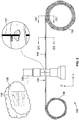
FIG. 1 is an isometric view illustrating a tape for collecting tissue samples in a manner compatible with imaging in a TEM system. -
FIG. 2 is a side view illustrating a TEM system in which tissue samples collected onto a tape are imaged via a microscope. -
FIG. 3A is a cross-sectional view alonglines 3A-3A ofFIG. 2 and illustrates the tape in an unstacked configuration. -
FIG. 3B is a cross-sectional view alonglines 3B-3B ofFIG. 2 and illustrates the tape in a stacked configuration. -
FIG. 4 is a top view illustrating a top surface of the tape ofFIG. 1 . -
FIG. 5 is a bottom view illustrating a trough of the tape ofFIG. 1 . - While the invention is susceptible to various modifications and alternative forms, specific embodiments have been shown by way of example in the drawings and will be described in detail herein. It should be understood, however, that the invention is not intended to be limited to the particular forms disclosed. Rather, the invention is to cover all modifications, equivalents, and alternatives falling within the spirit and scope of the invention as defined by the appended claims.
- While this invention is susceptible of embodiment in many different forms, there is shown in the drawings and will herein be described in detail preferred embodiments of the invention with the understanding that the present disclosure is to be considered as an exemplification of the principles of the invention and is not intended to limit the broad aspect of the invention to the embodiments illustrated. For purposes of the present detailed description, the singular includes the plural and vice versa (unless specifically disclaimed); the words "and" and "or" shall be both conjunctive and disjunctive; the word "all" means "any and all"; the word "any" means "any and all"; and the word "including" means "including without limitation."
- Referring to
FIG. 1 , atape 100 includes a TEM-compatiblecontinuous tape substrate 102 that allows the use of automated sample collection and handling techniques. Thetape 100 provides direct benefits, for example, in the collection of large TEM datasets that are common in neuroscience research, which seeks to understand the function of the brain. In other examples, thetape 100 is beneficial in any field that uses TEM, including medical diagnostics. Thus, thetape 100 is compatible with existing automated sample sectioning and collection approaches, but has key features that make it possible, for example, to use a transmission electron microscope instead of scanning electron microscope systems that are currently used for imaging in the neuroscience field. - The
tape 100 includes a plurality ofapertures 104, which resemble traditional TEM slot grids, and asupport film 106 that is attached to atop surface 108 of the tape substrate to cover eachaperture 104. Consequently, the support film provides structural support fortissue samples 110 deposited unto thetape 100 for TEM imaging. Thetape 100 further includes a plurality ofbarcodes 112, eachbarcode 112 being aligned with arespective aperture 104 for identifying or referencing arespective tissue sample 110. Thetape 100 also includes a plurality ofvents 114, eachvent 114 being aligned with a respective aperture for providing an air and moisture removal path when specific vacuum conditions are desired. - The
tape 100 is flexible such that it can achieve astacked configuration 120 in which thetape 100 is rolled unto itself, optionally being spooled unto a supporting reel, resulting in a plurality ofconcentric layers 122. Thetape 100 further has anunstacked configuration 122 in which thetape 100 is unwound in a straight path for observing one or more of thetissue samples 108. - To achieve the stacked and unstacked configuration, the
tape 100 includes a flexible material such as a polyimide film or other polymers. By way of example, the material includes an aluminum-coated polyimide film, a platinum-coated polyimide film, a conductive polyimide film, a polyether ether ketone (PEEK) polymer, and a polyethylene terephthalate (PET) polymer. In another more specific example, the material is a KAPTON® polyimide film. One considering factor for selecting the material includes the material's ability to be etched with ultraviolet light. Another factor for selecting the material includes conductivity for being compatible with imaging requirements. - In accordance with one example, the
tape 100 has a thickness TT (along a Z axis) of approximately 125 micrometers, a tape width TW (along a Y axis) of approximately 8 millimeters, and a tape length TL (along an X axis) of up to approximately 30 meters. In accordance with other examples, the tape thickness TT is 50 micrometers or larger to provide sufficient structural integrity. - Optionally, the
tape 100 further includes a plurality ofsmall inter-slot holes 150 located betweenapertures 104. According to one example, the holes have a generally square shape of approximately 250 micrometers x 250 micrometers. The inter-slot holes 150 provide a beneficial features in which background images of just the support film 106 (on top of the tape 100) are captured. The background images are, then, subtracted from the raw data. - Referring to
FIG. 2 , aTEM system 130 includes a sendingsupport reel 132 on which thetape 100 is initially stored and a receivingsupport reel 134 on which thetape 100 is subsequently transferred aftertissue samples 108 have been imaged or observed via atransmission electron microscope 136. By way of example, the imaging optionally forms a reconstructed three-dimensional image volume 138 associated with thetissue samples 108, and which includes a representativesingle section 139 of the three-dimensional image volume 138. More specifically, in the illustrated example, anelectron beam 137 is produced by thetransmission electron microscope 136 to image physicalserial sections 108 that can be virtually reconstructed into theimage volume 138 of a larval zebrafish. Theserial sections 108 had been previously cut into thousands of thin sections that were, then, collected onto thetape 100. - Referring to
FIG. 3A , a cross-sectional view of an unstacked section shows that thetape 100 has atrough 140 formed by twoside walls bottom surface 146 of thetape substrate 102. One benefit of thetrough 140 is that it allows thetape 100 to roll onto itself, into thestacked configuration 120, without damaging thetissue samples 108 or thesupport film 106. - The
trough 140 is defined by thebottom surface 146 of the tape substrate andinternal surfaces side walls open side 148 extending betweenbottom surface side walls side walls external surfaces tape substrate 102 in a transverse direction (i.e., across its width, along the Y-axis). - In the illustrated example, the
trough 140 is generally in the form of a C-shaped channel. However, in other embodiments, thetrough 140 has other forms or shapes. By way of a specific example, thetrough 140 has a depth XD of approximately 25 micrometers. In other specific examples, the trough depth XD has a range of approximately 6 micrometers to approximately 25 micrometers. - Referring to
FIG. 3B , thestacked configuration 120 shows afirst layer 122a that is immediately adjacent and in contact with asecond layer 122b, which is immediately adjacent and in contact with athird layer 122c. Specifically, bottom surfaces 142b, 144b of thefirst layer 122a are in contact with thesupport film 106 of thesecond layer 122b, andbottom surfaces support film 106 of thethird layer 122c. Beneficially, theside walls aperture 104 area to remain clear of therespective support film 106. More specifically, a distance D between theinternal surfaces side walls tissue sample 110. The distance D is less than the tape width TW, in accordance with a wall width between respectiveexternal surfaces internal surfaces side wall tape 100, thetrough 140 creates a natural protective zone in which the structural integrity of arespective tissue sample 110,support film 106, andaperture 104 is maintained without requiring additional, costly films or protective elements. - Referring to
FIG. 4 , thebarcodes 112 are located in proximity to an edge of thetape 100, have a generally rectangular shape, and are generally centered along the length of the tape 100 (along the X-axis) with respect to an associatedaperture 104. According to one example, abarcode 112 has a length BL of approximately 5 millimeters and a width BW of approximately 1 millimeter. - Referring to
FIG. 5 , thevents 114 are generally centered along the length of the tape 100 (along the X-axis) with respect to an associatedaperture 104. According to one example, avent 114 has a gap VG of approximately 0.1 micrometers (along the X-axis) and extends the full distance of eachside wall external surfaces internal surfaces - In accordance with a specific example, the
apertures 104 have an aperture length AL of approximately 2 millimeters, an aperture width of approximately 1.5 millimeters, and rounded corners RC with a radius of approximately 0.5 millimeters. In accordance with another specific example, theapertures 104 have an aperture length AL of approximately 3 millimeters, an aperture width of approximately 2 millimeters, and rounded corners RC with a radius of approximately 1 millimeter. In accordance with yet another specific example, theapertures 104 are spaced apart at a distance AS that is approximately 4 millimeters. - In accordance with one manufacturing method, the
tape 100 is made using a computer numerical control (CNC) ultraviolet (UV) laser system to etch theprotective trough 140 and to cleanly cut the apertures 104 (or slots) into a plastic web material. The CNC UV laser approach provides flexibility for addition of other features into and/or through thetape substrate 102, such as thebarcodes 112 for section identification, thevents 114 for reducing vacuum pump-down times when imagingtissue samples 110, and/or calibration marks to help configure thetape 100 for handling machines. - The
tape 100 provides many benefits over traditional TEM substrates. By way of example, thetape 100 maintains section order, avoids skipping of every other aperture position, and allows for automated sample collection using a commercially available instrument (e.g., ATUMtome, Boeckeler Instruments, Inc.). In another example, thetape 100 is beneficial because it is compatible with reel-to-reel processing and imaging techniques that greatly improve acquisition rates and reduce handling errors. In yet another example, thetape 100 and method of manufacturing is beneficial because the geometry configuration is customizable in accordance with specific needs. - Each of these embodiments and obvious variations thereof is contemplated as falling within the spirit and scope of the claimed invention, which is set forth in the following claims. Moreover, the present concepts expressly include any and all combinations and subcombinations of the preceding elements and aspects.
- In one embodiment there is provided a tape for collecting tissue samples in a manner compatible with imaging in a transmission electron microscopy (TEM) system, the tape comprising:
- a tape substrate having two side walls extending from a bottom surface to form a trough, the trough being defined by the bottom surface of the tape substrate and internal surfaces of the side walls, the trough having an open side between bottom surfaces of the side walls;
- a support film attached to a top surface of the tape substrate; and
- a plurality of apertures spaced at predetermined locations along the length of the tape substrate, each of the plurality of apertures being covered by the support film for receiving a respective tissue sample;
- wherein the tape includes a stacked configuration in which the tape substrate is wound in a plurality of layers along its length, the bottom surfaces of the side walls in a first layer of the plurality of layers being in contact with the support film in an immediately adjacent second layer of the plurality of layers, apertures of the plurality of apertures in the second layer being aligned within the trough of the first layer, between the side walls, for protecting structural integrity of the support film over each respective aperture.
- In one embodiment, the trough has a general c-shaped cross-section.
- In one embodiment, each aperture of the plurality of apertures has a generally rectangular shape and is equally spaced from each adjacent aperture of the plurality of apertures.
- In one embodiment, the plurality of apertures are centrally positioned across the width of the tape substrate.
- In one embodiment, the tape further comprises a plurality of vents in each of the side walls, each vent being in the form of a gap separation across the width of a respective side wall.
- In one embodiment, the tape further comprises a plurality of barcodes along the top surface of the tape substrate, each barcode of the plurality of barcodes being aligned with a respective aperture of the plurality of apertures.
- In one embodiment, the tape substrate is selected from a group consisting of aluminum-coated polyimide film, platinum-coated polyimide film, polyimide film, conductive polyimide film, polyether ether ketone (PEEK) polymer, and polyethylene terephthalate (PET) polymer.
- In one embodiment, the tape substrate has a width of approximately 8 millimeters and a thickness of approximately 125 micrometers, the trough having a depth of about 25 micrometers from the bottom surface of the tape substrate to the bottom surface of each side wall.
- In one embodiment, each aperture of the plurality of apertures is a rectangle having a length of approximately 2 millimeters and a width of approximately 1.5 millimeters, each aperture being spaced from adjacent apertures by approximately 4 millimeters.
- In one embodiment, the support film is an electron-lucent film.
- In another embodiment there is provided a tape for collecting tissue samples in a manner compatible with imaging in a transmission electron microscopy (TEM) system, the tape comprising:
- a substrate having a cross-section shape in the form of a channel with a top surface, a bottom surface, and a pair of side walls extending from the bottom surface, the side walls forming an internal space with an open side in proximity with bottom surfaces of the side walls, the substrate having a stacked configuration in which the substrate is arranged in several concentric layers along its length, the concentric layers including at least a first layer and an immediately adjacent second layer;
- a plurality of apertures centrally positioned across the width of the substrate and equally spaced along the length of the substrate, each aperture of the plurality of apertures being covered by the support film for receiving a respective tissue sample; and
- a support film covering at least in part each aperture of the plurality of apertures, the support film providing structural integrity for receiving a tissue sample over each aperture, the bottom surfaces of the side walls in the first layer being in contact with the support film or the top surface of the substrate in the second layer, each aperture in the second layer being aligned with the open side between the side walls.
- In one embodiment, the tape further comprises a plurality of vents in each of the side walls, each vent being in the form of a gap separation across the width of a respective side wall.
- In one embodiment, the tape further comprises a plurality of barcodes along the top surface of the substrate, each barcode of the plurality of barcodes being aligned with a respective aperture of the plurality of apertures.
- In one embodiment, each barcode has a generally rectangular shape with a width of approximately 1 millimeter and a length of approximately 5 millimeters.
- In one embodiment, the substrate is selected from a group consisting of aluminum-coated polyimide film, platinum-coated polyimide film, polyimide film, conductive polyimide film, polyether ether ketone (PEEK) polymer, and polyethylene terephthalate (PET) polymer.
- In one embodiment, the substrate has a width of approximately 8 millimeters and a thickness of approximately 125 micrometers.
- In one embodiment, each side wall has a depth of approximately 25 micrometers, the depth extending from the bottom surface of the substrate to the bottom surface of the side wall.
- In one embodiment, each aperture of the plurality of apertures has a generally rectangular shape with a length of approximately 2 millimeters and a width of approximately 1.5 millimeters, each aperture being spaced from adjacent apertures by approximately 4 millimeters.
- In one embodiment, the support film is a polyimide film.
- In one embodiment, the support film is an electron-lucent film.
- In one embodiment, the tape further comprises a plurality of inter-slot holes positioned between adjacent ones of the plurality of apertures.
- In one embodiment, at least one of the plurality of inter-slot holes has a generally square shape.
- In one embodiment, the generally square shape is approximately 250 micrometers x 250 micrometers.
Claims (13)
- A tape for collecting tissue samples in a manner compatible with imaging in a transmission electron microscopy (TEM) system, the tape comprising:a substrate having a cross-section shape in the form of a channel with a top surface, a bottom surface, and a pair of side walls extending from the bottom surface, the side walls forming an internal space with an open side in proximity with bottom surfaces of the side walls, the substrate having a stacked configuration in which the substrate is arranged in several concentric layers along its length, the concentric layers including at least a first layer and an immediately adjacent second layer;a plurality of apertures centrally positioned across the width of the substrate and equally spaced along the length of the substrate, each aperture of the plurality of apertures being covered by the support film for receiving a respective tissue sample; anda support film covering at least in part each aperture of the plurality of apertures, the support film providing structural integrity for receiving a tissue sample over each aperture, the bottom surfaces of the side walls in the first layer being in contact with the support film or the top surface of the substrate in the second layer, each aperture in the second layer being aligned with the open side between the side walls.
- The tape of claim 1, further comprising a plurality of vents in each of the side walls, each vent being in the form of a gap separation across the width of a respective side wall.
- The tape of claim 1, further comprising a plurality of barcodes along the top surface of the substrate, each barcode of the plurality of barcodes being aligned with a respective aperture of the plurality of apertures.
- The tape of claim 3, wherein each barcode has a generally rectangular shape with a width of approximately 1 millimeter and a length of approximately 5 millimeters.
- The tape of claim 1, wherein the substrate is selected from a group consisting of aluminum-coated polyimide film, platinum-coated polyimide film, polyimide film, conductive polyimide film, polyether ether ketone (PEEK) polymer, and polyethylene terephthalate (PET) polymer.
- The tape of claim 1, wherein the substrate has a width of approximately 8 millimeters and a thickness of approximately 125 micrometers.
- The tape of claim 1, wherein each side wall has a depth of approximately 25 micrometers, the depth extending from the bottom surface of the substrate to the bottom surface of the side wall.
- The tape of claim 1, wherein each aperture of the plurality of apertures has a generally rectangular shape with a length of approximately 2 millimeters and a width of approximately 1.5 millimeters, each aperture being spaced from adjacent apertures by approximately 4 millimeters.
- The tape of claim 1, wherein the support film is a polyimide film.
- The tape of claim 1, wherein the support film is an electron-lucent film.
- The tape of claim 1, further comprising a plurality of inter-slot holes positioned between adjacent ones of the plurality of apertures.
- The tape of claim 11, wherein at least one of the plurality of inter-slot holes has a generally square shape.
- The tape of claim 12, wherein the generally square shape is approximately 250 micrometers x 250 micrometers.
Applications Claiming Priority (3)
| Application Number | Priority Date | Filing Date | Title |
|---|---|---|---|
| US201662325747P | 2016-04-21 | 2016-04-21 | |
| PCT/US2017/028164 WO2017184621A1 (en) | 2016-04-21 | 2017-04-18 | Gridtape for fast nanoscale imaging |
| EP17786479.0A EP3446093B1 (en) | 2016-04-21 | 2017-04-18 | Gridtape for fast nanoscale imaging |
Related Parent Applications (1)
| Application Number | Title | Priority Date | Filing Date |
|---|---|---|---|
| EP17786479.0A Division EP3446093B1 (en) | 2016-04-21 | 2017-04-18 | Gridtape for fast nanoscale imaging |
Publications (2)
| Publication Number | Publication Date |
|---|---|
| EP3865927A1 true EP3865927A1 (en) | 2021-08-18 |
| EP3865927B1 EP3865927B1 (en) | 2023-08-02 |
Family
ID=60116340
Family Applications (2)
| Application Number | Title | Priority Date | Filing Date |
|---|---|---|---|
| EP17786479.0A Active EP3446093B1 (en) | 2016-04-21 | 2017-04-18 | Gridtape for fast nanoscale imaging |
| EP21158599.7A Active EP3865927B1 (en) | 2016-04-21 | 2017-04-18 | Tape for collecting tissue samples |
Family Applications Before (1)
| Application Number | Title | Priority Date | Filing Date |
|---|---|---|---|
| EP17786479.0A Active EP3446093B1 (en) | 2016-04-21 | 2017-04-18 | Gridtape for fast nanoscale imaging |
Country Status (3)
| Country | Link |
|---|---|
| US (3) | US11280710B2 (en) |
| EP (2) | EP3446093B1 (en) |
| WO (1) | WO2017184621A1 (en) |
Families Citing this family (2)
| Publication number | Priority date | Publication date | Assignee | Title |
|---|---|---|---|---|
| PT3732482T (en) | 2017-12-28 | 2022-04-07 | Delaval Holding Ab | TAPE FOR ANALYSIS OF BIOMARKERS FROM A SAMPLE OF MILK |
| WO2019217873A1 (en) * | 2018-05-10 | 2019-11-14 | Protochips, Inc. | Sample support with fiducial indicia |
Citations (2)
| Publication number | Priority date | Publication date | Assignee | Title |
|---|---|---|---|---|
| DE1900808A1 (en) * | 1969-01-08 | 1970-08-20 | Tetronics Res And Dev Company | Examination device for a test substance stream as well as examination procedures |
| US8366857B2 (en) | 2004-07-08 | 2013-02-05 | Kenneth Hayworth | Methods, apparatus and systems for production, collection, handling, and imaging of tissue sections |
Family Cites Families (5)
| Publication number | Priority date | Publication date | Assignee | Title |
|---|---|---|---|---|
| US20030170359A1 (en) * | 1997-03-13 | 2003-09-11 | Garwood Anthony J. M. | Method for controlling water content with decontamination in meats |
| JP4564664B2 (en) | 1999-02-17 | 2010-10-20 | ルーシド インコーポレーテッド | Cassette for forming optical thin sections of retained tissue specimens |
| US8591436B2 (en) * | 2004-04-30 | 2013-11-26 | Roche Diagnostics Operations, Inc. | Lancets for bodily fluid sampling supplied on a tape |
| EP2539710A4 (en) * | 2010-02-25 | 2016-07-06 | Prairie Ventures Llc | SYSTEM AND METHOD FOR HANDLING, STORING AND ANALYZING ANATOMOPATHOLOGICAL SAMPLES |
| WO2012033842A2 (en) * | 2010-09-07 | 2012-03-15 | President And Fellows Of Harvard College | Methods, apparatuses and systems for collection of tissue sections |
-
2017
- 2017-04-18 US US16/095,568 patent/US11280710B2/en active Active
- 2017-04-18 EP EP17786479.0A patent/EP3446093B1/en active Active
- 2017-04-18 WO PCT/US2017/028164 patent/WO2017184621A1/en not_active Ceased
- 2017-04-18 EP EP21158599.7A patent/EP3865927B1/en active Active
-
2022
- 2022-01-27 US US17/586,727 patent/US12152970B2/en active Active
-
2024
- 2024-08-09 US US18/800,004 patent/US20240402059A1/en active Pending
Patent Citations (2)
| Publication number | Priority date | Publication date | Assignee | Title |
|---|---|---|---|---|
| DE1900808A1 (en) * | 1969-01-08 | 1970-08-20 | Tetronics Res And Dev Company | Examination device for a test substance stream as well as examination procedures |
| US8366857B2 (en) | 2004-07-08 | 2013-02-05 | Kenneth Hayworth | Methods, apparatus and systems for production, collection, handling, and imaging of tissue sections |
Also Published As
| Publication number | Publication date |
|---|---|
| US20220155190A1 (en) | 2022-05-19 |
| US11280710B2 (en) | 2022-03-22 |
| US20200355583A1 (en) | 2020-11-12 |
| US20240402059A1 (en) | 2024-12-05 |
| EP3446093A1 (en) | 2019-02-27 |
| WO2017184621A1 (en) | 2017-10-26 |
| EP3446093B1 (en) | 2021-02-24 |
| EP3865927B1 (en) | 2023-08-02 |
| EP3446093A4 (en) | 2020-01-01 |
| US12152970B2 (en) | 2024-11-26 |
Similar Documents
| Publication | Publication Date | Title |
|---|---|---|
| US20240402059A1 (en) | GridTape For Fast Nanoscale Imaging | |
| JP6227556B2 (en) | Automatic smear preparation device | |
| EP2614376B1 (en) | Methods and systems for collection of tissue sections | |
| KR102466681B1 (en) | Deposition mask and method of manufacturing the deposition mask | |
| KR102231731B1 (en) | Direct self assembly in target design and production | |
| KR20220156656A (en) | Intermediate product | |
| EP3661709B1 (en) | Film cutting device having a linear actuator | |
| CN110337706B (en) | Freezable fluid cell for cryoelectron microscope | |
| DE202019003287U1 (en) | Material box for automatic storage with a detection and positioning structure | |
| EP3606709A1 (en) | Cutting machine with overview camera | |
| US20130108524A1 (en) | Tape cassette and method for the manufacture thereof | |
| CN117554410B (en) | Photoetching machine substrate surface liquid film thermal analysis method | |
| US7531216B2 (en) | Two-layer shadow mask with small dimension apertures and method of making and using same | |
| JP6943617B2 (en) | Substrate for printed wiring board and manufacturing method of printed wiring board | |
| EP1969340B1 (en) | Microdissection method and microdissection system | |
| JP7787829B2 (en) | Method for producing a series of ultrathin sections using an ultramicrotome, method for three-dimensional reconstruction of a microscopic sample, ultramicrotome system and computer program | |
| WO2016177369A9 (en) | Device and method for measuring the width and thickness of a flat object | |
| DE102022104471A1 (en) | Measuring device for measuring the alignment and/or orientation of segments in the energy cell-producing industry and method for producing segments | |
| AU2016265586B2 (en) | Method and instrument for processing sample carrier cards | |
| JP5699320B2 (en) | Roll film base | |
| JP5622089B2 (en) | Moisture content adjusting method for plastic film, method for producing color filter, and moisture content adjusting device for plastic film | |
| JP2009074984A (en) | Method for preparing cross-section specimen | |
| WO2019217873A1 (en) | Sample support with fiducial indicia | |
| CN111531628B (en) | Pathological section cutting device and adjusting method thereof | |
| DE102024119064A1 (en) | Method for operating an autonomous vehicle in an environment and autonomous vehicle |
Legal Events
| Date | Code | Title | Description |
|---|---|---|---|
| PUAI | Public reference made under article 153(3) epc to a published international application that has entered the european phase |
Free format text: ORIGINAL CODE: 0009012 |
|
| STAA | Information on the status of an ep patent application or granted ep patent |
Free format text: STATUS: THE APPLICATION HAS BEEN PUBLISHED |
|
| AC | Divisional application: reference to earlier application |
Ref document number: 3446093 Country of ref document: EP Kind code of ref document: P |
|
| AK | Designated contracting states |
Kind code of ref document: A1 Designated state(s): AL AT BE BG CH CY CZ DE DK EE ES FI FR GB GR HR HU IE IS IT LI LT LU LV MC MK MT NL NO PL PT RO RS SE SI SK SM TR |
|
| STAA | Information on the status of an ep patent application or granted ep patent |
Free format text: STATUS: REQUEST FOR EXAMINATION WAS MADE |
|
| 17P | Request for examination filed |
Effective date: 20220216 |
|
| RBV | Designated contracting states (corrected) |
Designated state(s): AL AT BE BG CH CY CZ DE DK EE ES FI FR GB GR HR HU IE IS IT LI LT LU LV MC MK MT NL NO PL PT RO RS SE SI SK SM TR |
|
| GRAP | Despatch of communication of intention to grant a patent |
Free format text: ORIGINAL CODE: EPIDOSNIGR1 |
|
| RIC1 | Information provided on ipc code assigned before grant |
Ipc: H01J 37/20 20060101ALN20230131BHEP Ipc: G01N 1/06 20060101ALI20230131BHEP Ipc: B01L 3/00 20060101ALI20230131BHEP Ipc: G01N 1/36 20060101ALI20230131BHEP Ipc: G01N 35/00 20060101ALI20230131BHEP Ipc: G02B 21/34 20060101AFI20230131BHEP |
|
| STAA | Information on the status of an ep patent application or granted ep patent |
Free format text: STATUS: GRANT OF PATENT IS INTENDED |
|
| RIC1 | Information provided on ipc code assigned before grant |
Ipc: H01J 37/20 20060101ALN20230209BHEP Ipc: G01N 1/06 20060101ALI20230209BHEP Ipc: B01L 3/00 20060101ALI20230209BHEP Ipc: G01N 1/36 20060101ALI20230209BHEP Ipc: G01N 35/00 20060101ALI20230209BHEP Ipc: G02B 21/34 20060101AFI20230209BHEP |
|
| RIC1 | Information provided on ipc code assigned before grant |
Ipc: H01J 37/20 20060101ALN20230223BHEP Ipc: G01N 1/06 20060101ALI20230223BHEP Ipc: B01L 3/00 20060101ALI20230223BHEP Ipc: G01N 1/36 20060101ALI20230223BHEP Ipc: G01N 35/00 20060101ALI20230223BHEP Ipc: G02B 21/34 20060101AFI20230223BHEP |
|
| INTG | Intention to grant announced |
Effective date: 20230309 |
|
| GRAS | Grant fee paid |
Free format text: ORIGINAL CODE: EPIDOSNIGR3 |
|
| GRAA | (expected) grant |
Free format text: ORIGINAL CODE: 0009210 |
|
| STAA | Information on the status of an ep patent application or granted ep patent |
Free format text: STATUS: THE PATENT HAS BEEN GRANTED |
|
| AC | Divisional application: reference to earlier application |
Ref document number: 3446093 Country of ref document: EP Kind code of ref document: P |
|
| AK | Designated contracting states |
Kind code of ref document: B1 Designated state(s): AL AT BE BG CH CY CZ DE DK EE ES FI FR GB GR HR HU IE IS IT LI LT LU LV MC MK MT NL NO PL PT RO RS SE SI SK SM TR |
|
| REG | Reference to a national code |
Ref country code: GB Ref legal event code: FG4D |
|
| REG | Reference to a national code |
Ref country code: CH Ref legal event code: EP |
|
| REG | Reference to a national code |
Ref country code: DE Ref legal event code: R096 Ref document number: 602017072370 Country of ref document: DE |
|
| REG | Reference to a national code |
Ref country code: IE Ref legal event code: FG4D |
|
| REG | Reference to a national code |
Ref country code: NL Ref legal event code: FP |
|
| P01 | Opt-out of the competence of the unified patent court (upc) registered |
Effective date: 20230914 |
|
| REG | Reference to a national code |
Ref country code: LT Ref legal event code: MG9D |
|
| REG | Reference to a national code |
Ref country code: AT Ref legal event code: MK05 Ref document number: 1595441 Country of ref document: AT Kind code of ref document: T Effective date: 20230802 |
|
| PG25 | Lapsed in a contracting state [announced via postgrant information from national office to epo] |
Ref country code: GR Free format text: LAPSE BECAUSE OF FAILURE TO SUBMIT A TRANSLATION OF THE DESCRIPTION OR TO PAY THE FEE WITHIN THE PRESCRIBED TIME-LIMIT Effective date: 20231103 |
|
| PG25 | Lapsed in a contracting state [announced via postgrant information from national office to epo] |
Ref country code: IS Free format text: LAPSE BECAUSE OF FAILURE TO SUBMIT A TRANSLATION OF THE DESCRIPTION OR TO PAY THE FEE WITHIN THE PRESCRIBED TIME-LIMIT Effective date: 20231202 |
|
| PG25 | Lapsed in a contracting state [announced via postgrant information from national office to epo] |
Ref country code: SE Free format text: LAPSE BECAUSE OF FAILURE TO SUBMIT A TRANSLATION OF THE DESCRIPTION OR TO PAY THE FEE WITHIN THE PRESCRIBED TIME-LIMIT Effective date: 20230802 Ref country code: RS Free format text: LAPSE BECAUSE OF FAILURE TO SUBMIT A TRANSLATION OF THE DESCRIPTION OR TO PAY THE FEE WITHIN THE PRESCRIBED TIME-LIMIT Effective date: 20230802 Ref country code: PT Free format text: LAPSE BECAUSE OF FAILURE TO SUBMIT A TRANSLATION OF THE DESCRIPTION OR TO PAY THE FEE WITHIN THE PRESCRIBED TIME-LIMIT Effective date: 20231204 Ref country code: NO Free format text: LAPSE BECAUSE OF FAILURE TO SUBMIT A TRANSLATION OF THE DESCRIPTION OR TO PAY THE FEE WITHIN THE PRESCRIBED TIME-LIMIT Effective date: 20231102 Ref country code: LV Free format text: LAPSE BECAUSE OF FAILURE TO SUBMIT A TRANSLATION OF THE DESCRIPTION OR TO PAY THE FEE WITHIN THE PRESCRIBED TIME-LIMIT Effective date: 20230802 Ref country code: LT Free format text: LAPSE BECAUSE OF FAILURE TO SUBMIT A TRANSLATION OF THE DESCRIPTION OR TO PAY THE FEE WITHIN THE PRESCRIBED TIME-LIMIT Effective date: 20230802 Ref country code: IS Free format text: LAPSE BECAUSE OF FAILURE TO SUBMIT A TRANSLATION OF THE DESCRIPTION OR TO PAY THE FEE WITHIN THE PRESCRIBED TIME-LIMIT Effective date: 20231202 Ref country code: HR Free format text: LAPSE BECAUSE OF FAILURE TO SUBMIT A TRANSLATION OF THE DESCRIPTION OR TO PAY THE FEE WITHIN THE PRESCRIBED TIME-LIMIT Effective date: 20230802 Ref country code: GR Free format text: LAPSE BECAUSE OF FAILURE TO SUBMIT A TRANSLATION OF THE DESCRIPTION OR TO PAY THE FEE WITHIN THE PRESCRIBED TIME-LIMIT Effective date: 20231103 Ref country code: FI Free format text: LAPSE BECAUSE OF FAILURE TO SUBMIT A TRANSLATION OF THE DESCRIPTION OR TO PAY THE FEE WITHIN THE PRESCRIBED TIME-LIMIT Effective date: 20230802 Ref country code: AT Free format text: LAPSE BECAUSE OF FAILURE TO SUBMIT A TRANSLATION OF THE DESCRIPTION OR TO PAY THE FEE WITHIN THE PRESCRIBED TIME-LIMIT Effective date: 20230802 |
|
| PG25 | Lapsed in a contracting state [announced via postgrant information from national office to epo] |
Ref country code: PL Free format text: LAPSE BECAUSE OF FAILURE TO SUBMIT A TRANSLATION OF THE DESCRIPTION OR TO PAY THE FEE WITHIN THE PRESCRIBED TIME-LIMIT Effective date: 20230802 |
|
| PG25 | Lapsed in a contracting state [announced via postgrant information from national office to epo] |
Ref country code: ES Free format text: LAPSE BECAUSE OF FAILURE TO SUBMIT A TRANSLATION OF THE DESCRIPTION OR TO PAY THE FEE WITHIN THE PRESCRIBED TIME-LIMIT Effective date: 20230802 |
|
| PG25 | Lapsed in a contracting state [announced via postgrant information from national office to epo] |
Ref country code: SM Free format text: LAPSE BECAUSE OF FAILURE TO SUBMIT A TRANSLATION OF THE DESCRIPTION OR TO PAY THE FEE WITHIN THE PRESCRIBED TIME-LIMIT Effective date: 20230802 Ref country code: RO Free format text: LAPSE BECAUSE OF FAILURE TO SUBMIT A TRANSLATION OF THE DESCRIPTION OR TO PAY THE FEE WITHIN THE PRESCRIBED TIME-LIMIT Effective date: 20230802 Ref country code: ES Free format text: LAPSE BECAUSE OF FAILURE TO SUBMIT A TRANSLATION OF THE DESCRIPTION OR TO PAY THE FEE WITHIN THE PRESCRIBED TIME-LIMIT Effective date: 20230802 Ref country code: EE Free format text: LAPSE BECAUSE OF FAILURE TO SUBMIT A TRANSLATION OF THE DESCRIPTION OR TO PAY THE FEE WITHIN THE PRESCRIBED TIME-LIMIT Effective date: 20230802 Ref country code: DK Free format text: LAPSE BECAUSE OF FAILURE TO SUBMIT A TRANSLATION OF THE DESCRIPTION OR TO PAY THE FEE WITHIN THE PRESCRIBED TIME-LIMIT Effective date: 20230802 Ref country code: CZ Free format text: LAPSE BECAUSE OF FAILURE TO SUBMIT A TRANSLATION OF THE DESCRIPTION OR TO PAY THE FEE WITHIN THE PRESCRIBED TIME-LIMIT Effective date: 20230802 Ref country code: SK Free format text: LAPSE BECAUSE OF FAILURE TO SUBMIT A TRANSLATION OF THE DESCRIPTION OR TO PAY THE FEE WITHIN THE PRESCRIBED TIME-LIMIT Effective date: 20230802 |
|
| REG | Reference to a national code |
Ref country code: DE Ref legal event code: R097 Ref document number: 602017072370 Country of ref document: DE |
|
| PG25 | Lapsed in a contracting state [announced via postgrant information from national office to epo] |
Ref country code: IT Free format text: LAPSE BECAUSE OF FAILURE TO SUBMIT A TRANSLATION OF THE DESCRIPTION OR TO PAY THE FEE WITHIN THE PRESCRIBED TIME-LIMIT Effective date: 20230802 |
|
| PLBE | No opposition filed within time limit |
Free format text: ORIGINAL CODE: 0009261 |
|
| STAA | Information on the status of an ep patent application or granted ep patent |
Free format text: STATUS: NO OPPOSITION FILED WITHIN TIME LIMIT |
|
| 26N | No opposition filed |
Effective date: 20240503 |
|
| PG25 | Lapsed in a contracting state [announced via postgrant information from national office to epo] |
Ref country code: SI Free format text: LAPSE BECAUSE OF FAILURE TO SUBMIT A TRANSLATION OF THE DESCRIPTION OR TO PAY THE FEE WITHIN THE PRESCRIBED TIME-LIMIT Effective date: 20230802 |
|
| PG25 | Lapsed in a contracting state [announced via postgrant information from national office to epo] |
Ref country code: BG Free format text: LAPSE BECAUSE OF FAILURE TO SUBMIT A TRANSLATION OF THE DESCRIPTION OR TO PAY THE FEE WITHIN THE PRESCRIBED TIME-LIMIT Effective date: 20230802 |
|
| PG25 | Lapsed in a contracting state [announced via postgrant information from national office to epo] |
Ref country code: MC Free format text: LAPSE BECAUSE OF FAILURE TO SUBMIT A TRANSLATION OF THE DESCRIPTION OR TO PAY THE FEE WITHIN THE PRESCRIBED TIME-LIMIT Effective date: 20230802 |
|
| PG25 | Lapsed in a contracting state [announced via postgrant information from national office to epo] |
Ref country code: MC Free format text: LAPSE BECAUSE OF FAILURE TO SUBMIT A TRANSLATION OF THE DESCRIPTION OR TO PAY THE FEE WITHIN THE PRESCRIBED TIME-LIMIT Effective date: 20230802 Ref country code: BG Free format text: LAPSE BECAUSE OF FAILURE TO SUBMIT A TRANSLATION OF THE DESCRIPTION OR TO PAY THE FEE WITHIN THE PRESCRIBED TIME-LIMIT Effective date: 20230802 |
|
| PG25 | Lapsed in a contracting state [announced via postgrant information from national office to epo] |
Ref country code: LU Free format text: LAPSE BECAUSE OF NON-PAYMENT OF DUE FEES Effective date: 20240418 |
|
| REG | Reference to a national code |
Ref country code: BE Ref legal event code: MM Effective date: 20240430 |
|
| PG25 | Lapsed in a contracting state [announced via postgrant information from national office to epo] |
Ref country code: LU Free format text: LAPSE BECAUSE OF NON-PAYMENT OF DUE FEES Effective date: 20240418 |
|
| PG25 | Lapsed in a contracting state [announced via postgrant information from national office to epo] |
Ref country code: BE Free format text: LAPSE BECAUSE OF NON-PAYMENT OF DUE FEES Effective date: 20240430 |
|
| PG25 | Lapsed in a contracting state [announced via postgrant information from national office to epo] |
Ref country code: BE Free format text: LAPSE BECAUSE OF NON-PAYMENT OF DUE FEES Effective date: 20240430 |
|
| PG25 | Lapsed in a contracting state [announced via postgrant information from national office to epo] |
Ref country code: IE Free format text: LAPSE BECAUSE OF NON-PAYMENT OF DUE FEES Effective date: 20240418 |
|
| PGFP | Annual fee paid to national office [announced via postgrant information from national office to epo] |
Ref country code: NL Payment date: 20250427 Year of fee payment: 9 |
|
| PGFP | Annual fee paid to national office [announced via postgrant information from national office to epo] |
Ref country code: DE Payment date: 20250429 Year of fee payment: 9 |
|
| PGFP | Annual fee paid to national office [announced via postgrant information from national office to epo] |
Ref country code: GB Payment date: 20250428 Year of fee payment: 9 |
|
| PGFP | Annual fee paid to national office [announced via postgrant information from national office to epo] |
Ref country code: FR Payment date: 20250425 Year of fee payment: 9 |
|
| PGFP | Annual fee paid to national office [announced via postgrant information from national office to epo] |
Ref country code: CH Payment date: 20250501 Year of fee payment: 9 |
|
| PG25 | Lapsed in a contracting state [announced via postgrant information from national office to epo] |
Ref country code: CY Free format text: LAPSE BECAUSE OF FAILURE TO SUBMIT A TRANSLATION OF THE DESCRIPTION OR TO PAY THE FEE WITHIN THE PRESCRIBED TIME-LIMIT; INVALID AB INITIO Effective date: 20170418 |
|
| PG25 | Lapsed in a contracting state [announced via postgrant information from national office to epo] |
Ref country code: HU Free format text: LAPSE BECAUSE OF FAILURE TO SUBMIT A TRANSLATION OF THE DESCRIPTION OR TO PAY THE FEE WITHIN THE PRESCRIBED TIME-LIMIT; INVALID AB INITIO Effective date: 20170418 |
|
| REG | Reference to a national code |
Ref country code: CH Ref legal event code: U11 Free format text: ST27 STATUS EVENT CODE: U-0-0-U10-U11 (AS PROVIDED BY THE NATIONAL OFFICE) Effective date: 20260501 |