EP3865912A1 - System and method for determining vehicle location - Google Patents
System and method for determining vehicle location Download PDFInfo
- Publication number
- EP3865912A1 EP3865912A1 EP21156024.8A EP21156024A EP3865912A1 EP 3865912 A1 EP3865912 A1 EP 3865912A1 EP 21156024 A EP21156024 A EP 21156024A EP 3865912 A1 EP3865912 A1 EP 3865912A1
- Authority
- EP
- European Patent Office
- Prior art keywords
- detector
- signal
- signal information
- source
- vehicle
- Prior art date
- Legal status (The legal status is an assumption and is not a legal conclusion. Google has not performed a legal analysis and makes no representation as to the accuracy of the status listed.)
- Granted
Links
Images

Classifications
-
- G—PHYSICS
- G01—MEASURING; TESTING
- G01S—RADIO DIRECTION-FINDING; RADIO NAVIGATION; DETERMINING DISTANCE OR VELOCITY BY USE OF RADIO WAVES; LOCATING OR PRESENCE-DETECTING BY USE OF THE REFLECTION OR RERADIATION OF RADIO WAVES; ANALOGOUS ARRANGEMENTS USING OTHER WAVES
- G01S19/00—Satellite radio beacon positioning systems; Determining position, velocity or attitude using signals transmitted by such systems
- G01S19/01—Satellite radio beacon positioning systems transmitting time-stamped messages, e.g. GPS [Global Positioning System], GLONASS [Global Orbiting Navigation Satellite System] or GALILEO
- G01S19/13—Receivers
- G01S19/24—Acquisition or tracking or demodulation of signals transmitted by the system
- G01S19/25—Acquisition or tracking or demodulation of signals transmitted by the system involving aiding data received from a cooperating element, e.g. assisted GPS
-
- G—PHYSICS
- G01—MEASURING; TESTING
- G01S—RADIO DIRECTION-FINDING; RADIO NAVIGATION; DETERMINING DISTANCE OR VELOCITY BY USE OF RADIO WAVES; LOCATING OR PRESENCE-DETECTING BY USE OF THE REFLECTION OR RERADIATION OF RADIO WAVES; ANALOGOUS ARRANGEMENTS USING OTHER WAVES
- G01S19/00—Satellite radio beacon positioning systems; Determining position, velocity or attitude using signals transmitted by such systems
- G01S19/01—Satellite radio beacon positioning systems transmitting time-stamped messages, e.g. GPS [Global Positioning System], GLONASS [Global Orbiting Navigation Satellite System] or GALILEO
- G01S19/13—Receivers
- G01S19/22—Multipath-related issues
-
- G—PHYSICS
- G01—MEASURING; TESTING
- G01C—MEASURING DISTANCES, LEVELS OR BEARINGS; SURVEYING; NAVIGATION; GYROSCOPIC INSTRUMENTS; PHOTOGRAMMETRY OR VIDEOGRAMMETRY
- G01C21/00—Navigation; Navigational instruments not provided for in groups G01C1/00 - G01C19/00
- G01C21/26—Navigation; Navigational instruments not provided for in groups G01C1/00 - G01C19/00 specially adapted for navigation in a road network
- G01C21/34—Route searching; Route guidance
- G01C21/3407—Route searching; Route guidance specially adapted for specific applications
- G01C21/3415—Dynamic re-routing, e.g. recalculating the route when the user deviates from calculated route or after detecting real-time traffic data or accidents
-
- G—PHYSICS
- G01—MEASURING; TESTING
- G01S—RADIO DIRECTION-FINDING; RADIO NAVIGATION; DETERMINING DISTANCE OR VELOCITY BY USE OF RADIO WAVES; LOCATING OR PRESENCE-DETECTING BY USE OF THE REFLECTION OR RERADIATION OF RADIO WAVES; ANALOGOUS ARRANGEMENTS USING OTHER WAVES
- G01S19/00—Satellite radio beacon positioning systems; Determining position, velocity or attitude using signals transmitted by such systems
- G01S19/38—Determining a navigation solution using signals transmitted by a satellite radio beacon positioning system
- G01S19/39—Determining a navigation solution using signals transmitted by a satellite radio beacon positioning system the satellite radio beacon positioning system transmitting time-stamped messages, e.g. GPS [Global Positioning System], GLONASS [Global Orbiting Navigation Satellite System] or GALILEO
- G01S19/42—Determining position
-
- G—PHYSICS
- G01—MEASURING; TESTING
- G01S—RADIO DIRECTION-FINDING; RADIO NAVIGATION; DETERMINING DISTANCE OR VELOCITY BY USE OF RADIO WAVES; LOCATING OR PRESENCE-DETECTING BY USE OF THE REFLECTION OR RERADIATION OF RADIO WAVES; ANALOGOUS ARRANGEMENTS USING OTHER WAVES
- G01S19/00—Satellite radio beacon positioning systems; Determining position, velocity or attitude using signals transmitted by such systems
- G01S19/38—Determining a navigation solution using signals transmitted by a satellite radio beacon positioning system
- G01S19/39—Determining a navigation solution using signals transmitted by a satellite radio beacon positioning system the satellite radio beacon positioning system transmitting time-stamped messages, e.g. GPS [Global Positioning System], GLONASS [Global Orbiting Navigation Satellite System] or GALILEO
- G01S19/42—Determining position
- G01S19/45—Determining position by combining measurements of signals from the satellite radio beacon positioning system with a supplementary measurement
- G01S19/46—Determining position by combining measurements of signals from the satellite radio beacon positioning system with a supplementary measurement the supplementary measurement being of a radio-wave signal type
-
- G—PHYSICS
- G01—MEASURING; TESTING
- G01S—RADIO DIRECTION-FINDING; RADIO NAVIGATION; DETERMINING DISTANCE OR VELOCITY BY USE OF RADIO WAVES; LOCATING OR PRESENCE-DETECTING BY USE OF THE REFLECTION OR RERADIATION OF RADIO WAVES; ANALOGOUS ARRANGEMENTS USING OTHER WAVES
- G01S5/00—Position-fixing by co-ordinating two or more direction or position line determinations; Position-fixing by co-ordinating two or more distance determinations
- G01S5/0009—Transmission of position information to remote stations
-
- G—PHYSICS
- G01—MEASURING; TESTING
- G01S—RADIO DIRECTION-FINDING; RADIO NAVIGATION; DETERMINING DISTANCE OR VELOCITY BY USE OF RADIO WAVES; LOCATING OR PRESENCE-DETECTING BY USE OF THE REFLECTION OR RERADIATION OF RADIO WAVES; ANALOGOUS ARRANGEMENTS USING OTHER WAVES
- G01S2205/00—Position-fixing by co-ordinating two or more direction or position line determinations; Position-fixing by co-ordinating two or more distance determinations
- G01S2205/001—Transmission of position information to remote stations
- G01S2205/002—Transmission of position information to remote stations for traffic control, mobile tracking, guidance, surveillance or anti-collision
Definitions
- Modern automotive vehicles include an increasing amount of electronic technology, such as navigation systems that are useful for route guidance or autonomous vehicle control, for example.
- Many navigation systems operate based on detecting satellite signals and using a known algorithm to determine the current vehicle location. The accuracy of the system depends on the quality of the received and processed satellite signals. There are situations in which satellite signals may not be entirely reliable.
- satellite signals it is possible for satellite signals to reflect off of nearby structures before being received by the navigation system antenna or detector. Such reflections increase the distance travelled by the signal before reaching the antenna or detector compared to a signal travelling directly from the satellite to the antenna or detector. Since a known position of the satellite from which such a signal originates is used for determining the location of the vehicle, any intermediate reflection and resulting increased signal travel distance can introduce errors in the vehicle location determination.
- An illustrative example embodiment of a system includes a detector configured to detect a signal from a source and provide first signal information regarding a distance a detected signal traveled between the source and the detector.
- a processor is configured to determine whether the first signal information corresponds to a direct signal path between the detector and the source or the first signal information corresponds to a reflected signal based on second signal information from at least one other detector that does not have a direct signal path between the other detector and the source.
- the processor determines a location of the detector based on the first signal information only when the first signal information corresponds to the direct signal path between the detector and the source.
- the first signal information comprises a pseudo range between the at least one source and the at least one detector
- the second signal information comprises a distance traveled by a reflected signal between the at least one source and the at least one other detector.
- the processor is configured to determine that the first signal information corresponds to a reflected signal by determining a difference between the pseudo range of the first signal information and the distance of the second signal information and determining that the determined difference is below a threshold.
- the processor is configured to determine that the first signal information corresponds to a reflected signal by determining that the pseudo range of the first signal information is greater than the distance of the second signal information.
- the at least one detector is associated with a vehicle and the determined location is a location of the vehicle.
- the processor is configured to determine whether the second signal information corresponds to a reflected signal between the at least one source and the at least one other detector by determining a position of the at least one other detector relative to the vehicle, determining a position of the vehicle relative to the at least one source, and determining that at least one portion of the vehicle obstructs a direct signal path between the at least one source and the at least one other detector based on the determined positions.
- the at least one portion of the vehicle comprises a vehicle roof and the processor uses information regarding at least one of a size of the roof and a shape of the roof to determine that the roof obstructs the direct signal path between the at least one source and the at least one other detector.
- An example embodiment including at least one of the features of the system of any of the previous paragraphs includes the at least one other detector and wherein the at least one other detector is situated in a known position relative to a portion of the vehicle where the portion of the vehicle obstructs a direct signal path between the at least one other detector and the at least one source.
- the at least one source is a satellite having a known location within an earth centered earth fixed reference frame.
- An illustrative example embodiment of a method includes: detecting a signal from at least one source, generating first signal information regarding a distance the detected signal traveled between the at least one source and at least one detector, and determining whether the first signal information corresponds to a direct signal path between the at least one detector and the at least one source or the first signal information corresponds to a reflected signal based on second signal information from at least one other detector that does not have a direct signal path between the at least one other detector and the at least one source, and determining a location of the at least one detector based on the first signal information when the first signal information corresponds to the direct signal path between the at least one detector and the at least one source.
- the first signal information comprises a pseudo range between the at least one source and the at least one detector and the second signal information comprises a distance traveled by a reflected signal between the at least one source and the at least one other detector.
- An example embodiment including at least one of the features of the method of any of the previous paragraphs includes determining that the first signal information corresponds to a reflected signal by determining a difference between the pseudo range of the first signal information and the distance of the second signal information and determining that the determined difference is below a threshold.
- An example embodiment including at least one of the features of the method of any of the previous paragraphs includes determining that the first signal information corresponds to a reflected signal by determining that the pseudo range of the first signal information is greater than the distance of the second signal information.
- the at least one detector is associated with a vehicle and the method comprises determining a location of the vehicle based on the determined location of the at least one detector.
- An example embodiment including at least one of the features of the method of any of the previous paragraphs includes determining whether the second signal information corresponds to a reflected signal between the at least one source and the at least one other detector by determining a position of the at least one other detector relative to the vehicle, determining a position of the vehicle relative to the at least one source, and determining that at least one portion of the vehicle obstructs a direct signal path between the at least one source and the at least one other detector based on the determined positions.
- the at least one portion of the vehicle comprises a vehicle roof and the method comprises using information regarding at least one of a size of the roof and a shape of the roof to determine that the roof obstructs the direct signal path between the at least one source and the at least one other detector.
- the at least one other detector is situated in a known position relative to a portion of the vehicle where the portion of the vehicle obstructs a direct signal path between the at least one other detector and the at least one source.
- the at least one source is a satellite having a known location within an earth centered earth fixed reference frame.
- An illustrative example embodiment of a vehicle navigation system includes detecting means for detecting a signal from at least one source and providing first signal information regarding a distance a detected signal traveled between the at least one source and the at least one detector; and means for determining whether the first signal information corresponds to a direct signal path between the at least one detector and the at least one source or the first signal information corresponds to a reflected signal based on second signal information from at least one other detector that does not have a direct signal path between the at least one other detector and the at least one source, and determining a location of the vehicle based on the first signal information when the first signal information corresponds to the direct signal path between the at least one detector and the at least one source.
- the at least one source is a satellite having a known location relative to an earth centered earth fixed reference frame
- the first signal information comprises a pseudo range between the at satellite and the at least one detector
- the second signal information comprises a distance traveled by a reflected signal between the at least one source and the at least one other detector.
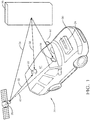
- Figure 1 schematically illustrates a system 20 including a detector 22 and a processor 24.
- the detector 22 includes an antenna or another device capable of detecting a signal from at least one source.
- the detector 22 is configured to detect satellite signals from a satellite 26. Only one satellite is shown for discussion purposes but the detector 22 will often detect multiple satellites.
- the detector 22 is configured to generate first signal information regarding a distance that a detected signal travels between the satellite 26 and the detector 22.
- the processor 24 includes a computing device and associated memory.
- the processor 24 in some embodiments is a device dedicated to processing signals from the detector 22 while in other embodiments the processor 24 is a device that performs other functions that may be unrelated to processing signals from the detector 22.
- the processor 24 is configured to determine whether the first signal information from the detector 22 corresponds to a direct signal path between the detector 22 and the satellite 26 or if the first signal information corresponds to a reflected signal. The processor 24 makes this determination based upon second signal information from at least one other detector 28 that provides the second signal information. When the detector 28 does not have a direct signal path between it and the satellite 26, any second signal information from the detector 28 regarding a signal detected from the satellite 26 is the result of a reflected signal detected by the detector 28.
- the system 20 is associated with a vehicle 30 and is useful for determining a location of the vehicle 30.
- the detector 28 is located within the vehicle 30 such that one or more portions of the vehicle 30 obstructs a direct signal path between the detector 28 and the satellite 26 under at least some conditions.
- the condition shown in Figure 1 includes a direct signal path 32 from the satellite 26 to the detector 22.
- First signal information from the detector 22 resulting from detecting a signal that travels along the direct signal path 32 is useful for determining a location of the detector 22 and the vehicle 30 because the satellite 26 has a known position relative to an earth centered earth fixed (ECEF) reference frame.
- ECEF earth centered earth fixed
- the detector 22 may detect a signal from the satellite 26 that is a reflected signal, which should not be used for making location determinations because the distance traveled by a reflected signal will introduce errors into the location determination, which is based in part on the known location of the satellite 26.
- a signal from the satellite 26 may travel along the path shown at 34 and reflect off a structure 36, such as a building nearby the path of the vehicle 30.
- the reflected signal may follow a path as schematically shown at 38 and be detected by the detector 22.
- the distance traveled by the signal following the path 34, 38 is different than the distance of a signal following the direct signal path 32 between the satellite 26 and the detector 22.
- the processor 24 utilizes first signal information from the detector corresponding to a signal following the direct signal path 32 but does not use first signal information from the detector 22 resulting from a reflected signal detected by the detector 22.
- the processor 24 uses second signal information from at least one other detector, such as the detector 28 situated in the vehicle 30, to determine whether the first signal information corresponds to a reflected signal. Given the current location of the satellite 26 and the position of the vehicle 30 relative to the satellite 26, no direct signal path exists between the satellite 26 and the detector 28. The potential direct signal path 40 is obstructed by the roof 42 of the vehicle 30. The position of the detector 28 in the vehicle 30 does allow for the detector 28 to detect a reflected signal from the satellite 26. For example, a signal following the path schematically shown at 34, reflecting off the structure 36 and then following the path schematically shown at 44 may pass through the windshield of the vehicle 30 and be detected by the detector 28.
- the processor 24 receives second signal information from the detector 28 indicating or corresponding to the distance traveled by the reflected signal following the path 34, 44.
- the processor 24 uses such second signal information for determining whether first signal information from the detector 22 should be used for purposes of determining a location of the detector 22 and the vehicle 30.
- Figure 2 includes a flowchart diagram 50 that summarizes an example method of determining the location.
- the detector 22 detects a signal from the satellite 26.
- the detector 22 generates first signal information regarding the distance the detected signal traveled between the satellite 26 and the detector 22.
- the first signal information comprises a pseudo range corresponding to the distance the signal traveled.
- the first signal information is provided to the processor 24.
- the processor 24 determines whether the first signal information corresponds to a direct signal path distance or a reflected distance based on second signal information from the detector 28, which is another pseudo range in this example.
- the processor 24 determines a difference between the distance of the first signal information and the distance of the second signal information.
- the processor 24 determines whether the difference between the distances of the first signal information and the second signal information is below a threshold or within a preselected range. When the second signal information is known to correspond to a reflected signal and the distance of the first signal information is sufficiently close to the distance of the reflected signal, the processor 24 determines that the first signal information is the result of the detector 22 detecting a reflected signal rather than a signal following a direct signal path between the satellite 26 and the detector 22.
- any nearby structure 36 from which a satellite signal may reflect resulting in a reflected signal is at least 1.5 meters away from the vehicle 30.
- a reflected signal likely will travel through such a spacing twice resulting in about three meters difference between the distance traveled by the reflected signal and a direct signal path that does not involve a reflection off that nearby structure 36.
- the processor 24 determines that the pseudo range or distance of the first signal information is the result of a reflected signal because the second signal information is known to be the result of detecting a reflected signal.
- the processor 24 determines the location of the detector 22 or the vehicle 30 based on the first signal information when the first signal information corresponds to detecting a signal received along a direct signal path. In some embodiments any signal that appears to be a reflected signal is rejected or excluded from the information used to determine the location of the vehicle 30 but some embodiments include using such signal information when a sufficiently reliable correction or adjustment can be made by the processor 24.
- the detector 28 is part of the system 20 and situated in a known position on the vehicle 30 where the detector 28 is likely to only be able to detect reflected signals from the satellite 26.
- the detector 28 may be situated relative to the interior of the vehicle 30 where the detector 28 will be effectively shielded by the roof of the vehicle 42 from any direct signal paths from the satellite 26 or other satellites that may be used for location determinations.
- the second signal information from the detector 28 is always known to correspond to a reflected signal.
- the detector 28 may be situated on the vehicle 30 in a location where a direct satellite signal path may be obstructed depending on the relative position of the vehicle 30 and the satellite 26. For example, there may be conditions under which the detector 28 has a direct line of sight through the windshield of the vehicle 30 to one or more satellites depending on the relative positions between such satellites and the vehicle 30.
- Figure 3 includes a flowchart diagram 60 that summarizes an example technique by which the processor 24 determines whether second signal information from the detector 28 corresponds to a reflected signal.
- the processor 24 determines a position of the detector 28 relative to the vehicle. This may be accomplished in different ways known to those skilled in the art depending on the embodiment. When the detector 28 is in a dedicated location on or in the vehicle 30, the position of the detector 28 is known. In other embodiments, the detector 28 is moveable relative to the vehicle 30, such as when the detector 28 is a personal communication device that has GPS capability, such as a cell phone. The processor 24 in such embodiments utilizes known locating techniques for locating a position of the detector 28 relative to the vehicle 30.
- the position of the moveable detector relative to the vehicle is determined using radio frequency transmissions from the detector that are received by a plurality of antennas distributed about the vehicle.
- the plurality of antennas may be components of a passive entry/passive start (PEPS) system that may be installed on the vehicle. Details for determining the position of the moveable detector are disclosed in US Patent Application Number 16/275,374 , which is incorporated herein by reference in full.
- PEPS passive entry/passive start
- the processor 24 determines a location of the vehicle 30 relative to the satellite 26. This may be accomplished, for example, by using a last known position or location of the vehicle 30 and the currently known position of the satellite 26, which is available through a known GNSS almanac to which the processor 24 has access. Based on that relationship and the position of the detector 28 relative to the vehicle 30, the processor 24 is able to determine whether a portion of the vehicle 30 obstructs a direct signal path between the satellite 26 and the detector 28, which provides the second signal information at 66.
- the processor 24 is provided with information regarding the size, shape or both of the vehicle roof 42 and uses that information combined with the relative positions of the vehicle 30 and the satellite 26 for determining when the roof 42 would obstruct a direct signal path between the detector 28 and the satellite 26.
- the illustrated example embodiment provides enhanced accuracy for location determinations, such as locating a vehicle. Accurate vehicle location is useful for guided navigation or autonomous vehicle control. By eliminating reflected signals from location determinations, the example system increases the accuracy and reliability of location determinations allowing for satisfying more stringent margin of error requirements.
Landscapes
- Engineering & Computer Science (AREA)
- Radar, Positioning & Navigation (AREA)
- Remote Sensing (AREA)
- Physics & Mathematics (AREA)
- General Physics & Mathematics (AREA)
- Computer Networks & Wireless Communication (AREA)
- Automation & Control Theory (AREA)
- Navigation (AREA)
- Position Fixing By Use Of Radio Waves (AREA)
Abstract
Description
- Modern automotive vehicles include an increasing amount of electronic technology, such as navigation systems that are useful for route guidance or autonomous vehicle control, for example. Many navigation systems operate based on detecting satellite signals and using a known algorithm to determine the current vehicle location. The accuracy of the system depends on the quality of the received and processed satellite signals. There are situations in which satellite signals may not be entirely reliable.
- For example, it is possible for satellite signals to reflect off of nearby structures before being received by the navigation system antenna or detector. Such reflections increase the distance travelled by the signal before reaching the antenna or detector compared to a signal travelling directly from the satellite to the antenna or detector. Since a known position of the satellite from which such a signal originates is used for determining the location of the vehicle, any intermediate reflection and resulting increased signal travel distance can introduce errors in the vehicle location determination.
- An illustrative example embodiment of a system includes a detector configured to detect a signal from a source and provide first signal information regarding a distance a detected signal traveled between the source and the detector. A processor is configured to determine whether the first signal information corresponds to a direct signal path between the detector and the source or the first signal information corresponds to a reflected signal based on second signal information from at least one other detector that does not have a direct signal path between the other detector and the source. The processor determines a location of the detector based on the first signal information only when the first signal information corresponds to the direct signal path between the detector and the source.
- In an example embodiment including at least one of the features of the system of the previous paragraph, the first signal information comprises a pseudo range between the at least one source and the at least one detector, and the second signal information comprises a distance traveled by a reflected signal between the at least one source and the at least one other detector.
- In an example embodiment including at least one of the features of the system of any of the previous paragraphs, the processor is configured to determine that the first signal information corresponds to a reflected signal by determining a difference between the pseudo range of the first signal information and the distance of the second signal information and determining that the determined difference is below a threshold.
- In an example embodiment including at least one of the features of the system of any of the previous paragraphs, the processor is configured to determine that the first signal information corresponds to a reflected signal by determining that the pseudo range of the first signal information is greater than the distance of the second signal information.
- In an example embodiment including at least one of the features of the system of any of the previous paragraphs, the at least one detector is associated with a vehicle and the determined location is a location of the vehicle.
- In an example embodiment including at least one of the features of the system of any of the previous paragraphs, the processor is configured to determine whether the second signal information corresponds to a reflected signal between the at least one source and the at least one other detector by determining a position of the at least one other detector relative to the vehicle, determining a position of the vehicle relative to the at least one source, and determining that at least one portion of the vehicle obstructs a direct signal path between the at least one source and the at least one other detector based on the determined positions.
- In an example embodiment including at least one of the features of the system of any of the previous paragraphs, the at least one portion of the vehicle comprises a vehicle roof and the processor uses information regarding at least one of a size of the roof and a shape of the roof to determine that the roof obstructs the direct signal path between the at least one source and the at least one other detector.
- An example embodiment including at least one of the features of the system of any of the previous paragraphs includes the at least one other detector and wherein the at least one other detector is situated in a known position relative to a portion of the vehicle where the portion of the vehicle obstructs a direct signal path between the at least one other detector and the at least one source.
- In an example embodiment including at least one of the features of the system of any of the previous paragraphs, the at least one source is a satellite having a known location within an earth centered earth fixed reference frame.
- An illustrative example embodiment of a method includes: detecting a signal from at least one source, generating first signal information regarding a distance the detected signal traveled between the at least one source and at least one detector, and determining whether the first signal information corresponds to a direct signal path between the at least one detector and the at least one source or the first signal information corresponds to a reflected signal based on second signal information from at least one other detector that does not have a direct signal path between the at least one other detector and the at least one source, and determining a location of the at least one detector based on the first signal information when the first signal information corresponds to the direct signal path between the at least one detector and the at least one source.
- In an example embodiment including at least one of the features of the method of the previous paragraph, the first signal information comprises a pseudo range between the at least one source and the at least one detector and the second signal information comprises a distance traveled by a reflected signal between the at least one source and the at least one other detector.
- An example embodiment including at least one of the features of the method of any of the previous paragraphs includes determining that the first signal information corresponds to a reflected signal by determining a difference between the pseudo range of the first signal information and the distance of the second signal information and determining that the determined difference is below a threshold.
- An example embodiment including at least one of the features of the method of any of the previous paragraphs includes determining that the first signal information corresponds to a reflected signal by determining that the pseudo range of the first signal information is greater than the distance of the second signal information.
- In an example embodiment including at least one of the features of the method of any of the previous paragraphs, the at least one detector is associated with a vehicle and the method comprises determining a location of the vehicle based on the determined location of the at least one detector.
- An example embodiment including at least one of the features of the method of any of the previous paragraphs includes determining whether the second signal information corresponds to a reflected signal between the at least one source and the at least one other detector by determining a position of the at least one other detector relative to the vehicle, determining a position of the vehicle relative to the at least one source, and determining that at least one portion of the vehicle obstructs a direct signal path between the at least one source and the at least one other detector based on the determined positions.
- In an example embodiment including at least one of the features of the method of any of the previous paragraphs, the at least one portion of the vehicle comprises a vehicle roof and the method comprises using information regarding at least one of a size of the roof and a shape of the roof to determine that the roof obstructs the direct signal path between the at least one source and the at least one other detector.
- In an example embodiment including at least one of the features of the method of any of the previous paragraphs, the at least one other detector is situated in a known position relative to a portion of the vehicle where the portion of the vehicle obstructs a direct signal path between the at least one other detector and the at least one source.
- In an example embodiment including at least one of the features of the method of any of the previous paragraphs, the at least one source is a satellite having a known location within an earth centered earth fixed reference frame.
- An illustrative example embodiment of a vehicle navigation system includes detecting means for detecting a signal from at least one source and providing first signal information regarding a distance a detected signal traveled between the at least one source and the at least one detector; and means for determining whether the first signal information corresponds to a direct signal path between the at least one detector and the at least one source or the first signal information corresponds to a reflected signal based on second signal information from at least one other detector that does not have a direct signal path between the at least one other detector and the at least one source, and determining a location of the vehicle based on the first signal information when the first signal information corresponds to the direct signal path between the at least one detector and the at least one source.
- In an example embodiment including at least one of the features of the system of the previous paragraph, the at least one source is a satellite having a known location relative to an earth centered earth fixed reference frame, the first signal information comprises a pseudo range between the at satellite and the at least one detector, the second signal information comprises a distance traveled by a reflected signal between the at least one source and the at least one other detector.
- The various features and advantages of at least one disclosed example embodiment will become apparent to those skilled in the art from the following detailed description. The drawings that accompany the detailed description can be briefly described as follows.
-
Figure 1 schematically illustrates an example embodiment of a system for determining a location of a vehicle. -
Figure 2 is a flowchart diagram summarizing an example embodiment of a method of determining a location. -
Figure 3 is a flowchart diagram summarizing an example method of determining when a direct signal path is available between a source and a detector. -
Figure 1 schematically illustrates asystem 20 including adetector 22 and aprocessor 24. Thedetector 22 includes an antenna or another device capable of detecting a signal from at least one source. In the embodiment shown inFigure 1 thedetector 22 is configured to detect satellite signals from asatellite 26. Only one satellite is shown for discussion purposes but thedetector 22 will often detect multiple satellites. Thedetector 22 is configured to generate first signal information regarding a distance that a detected signal travels between thesatellite 26 and thedetector 22. - The
processor 24 includes a computing device and associated memory. Theprocessor 24 in some embodiments is a device dedicated to processing signals from thedetector 22 while in other embodiments theprocessor 24 is a device that performs other functions that may be unrelated to processing signals from thedetector 22. Theprocessor 24 is configured to determine whether the first signal information from thedetector 22 corresponds to a direct signal path between thedetector 22 and thesatellite 26 or if the first signal information corresponds to a reflected signal. Theprocessor 24 makes this determination based upon second signal information from at least oneother detector 28 that provides the second signal information. When thedetector 28 does not have a direct signal path between it and thesatellite 26, any second signal information from thedetector 28 regarding a signal detected from thesatellite 26 is the result of a reflected signal detected by thedetector 28. - In the embodiment shown in
Figure 1 , thesystem 20 is associated with avehicle 30 and is useful for determining a location of thevehicle 30. Thedetector 28 is located within thevehicle 30 such that one or more portions of thevehicle 30 obstructs a direct signal path between thedetector 28 and thesatellite 26 under at least some conditions. - The condition shown in
Figure 1 includes adirect signal path 32 from thesatellite 26 to thedetector 22. First signal information from thedetector 22 resulting from detecting a signal that travels along thedirect signal path 32 is useful for determining a location of thedetector 22 and thevehicle 30 because thesatellite 26 has a known position relative to an earth centered earth fixed (ECEF) reference frame. - In the condition shown in
Figure 1 , it is also possible for thedetector 22 to detect a signal from thesatellite 26 that is a reflected signal, which should not be used for making location determinations because the distance traveled by a reflected signal will introduce errors into the location determination, which is based in part on the known location of thesatellite 26. For example, a signal from thesatellite 26 may travel along the path shown at 34 and reflect off astructure 36, such as a building nearby the path of thevehicle 30. The reflected signal may follow a path as schematically shown at 38 and be detected by thedetector 22. The distance traveled by the signal following thepath direct signal path 32 between thesatellite 26 and thedetector 22. Theprocessor 24 utilizes first signal information from the detector corresponding to a signal following thedirect signal path 32 but does not use first signal information from thedetector 22 resulting from a reflected signal detected by thedetector 22. - The
processor 24 uses second signal information from at least one other detector, such as thedetector 28 situated in thevehicle 30, to determine whether the first signal information corresponds to a reflected signal. Given the current location of thesatellite 26 and the position of thevehicle 30 relative to thesatellite 26, no direct signal path exists between thesatellite 26 and thedetector 28. The potentialdirect signal path 40 is obstructed by theroof 42 of thevehicle 30. The position of thedetector 28 in thevehicle 30 does allow for thedetector 28 to detect a reflected signal from thesatellite 26. For example, a signal following the path schematically shown at 34, reflecting off thestructure 36 and then following the path schematically shown at 44 may pass through the windshield of thevehicle 30 and be detected by thedetector 28. Theprocessor 24 receives second signal information from thedetector 28 indicating or corresponding to the distance traveled by the reflected signal following thepath processor 24 uses such second signal information for determining whether first signal information from thedetector 22 should be used for purposes of determining a location of thedetector 22 and thevehicle 30. -
Figure 2 includes a flowchart diagram 50 that summarizes an example method of determining the location. At 52, thedetector 22 detects a signal from thesatellite 26. At 54, thedetector 22 generates first signal information regarding the distance the detected signal traveled between thesatellite 26 and thedetector 22. In this example embodiment, the first signal information comprises a pseudo range corresponding to the distance the signal traveled. The first signal information is provided to theprocessor 24. At 56, theprocessor 24 determines whether the first signal information corresponds to a direct signal path distance or a reflected distance based on second signal information from thedetector 28, which is another pseudo range in this example. Theprocessor 24 determines a difference between the distance of the first signal information and the distance of the second signal information. Theprocessor 24 determines whether the difference between the distances of the first signal information and the second signal information is below a threshold or within a preselected range. When the second signal information is known to correspond to a reflected signal and the distance of the first signal information is sufficiently close to the distance of the reflected signal, theprocessor 24 determines that the first signal information is the result of thedetector 22 detecting a reflected signal rather than a signal following a direct signal path between thesatellite 26 and thedetector 22. - For example, when the location of interest is the location of the
vehicle 30, it can be assumed that anynearby structure 36 from which a satellite signal may reflect resulting in a reflected signal is at least 1.5 meters away from thevehicle 30. A reflected signal likely will travel through such a spacing twice resulting in about three meters difference between the distance traveled by the reflected signal and a direct signal path that does not involve a reflection off thatnearby structure 36. In this example, whenever the difference between the distances of the first signal information and the second signal information is within three meters, theprocessor 24 determines that the pseudo range or distance of the first signal information is the result of a reflected signal because the second signal information is known to be the result of detecting a reflected signal. - At 58, the
processor 24 determines the location of thedetector 22 or thevehicle 30 based on the first signal information when the first signal information corresponds to detecting a signal received along a direct signal path. In some embodiments any signal that appears to be a reflected signal is rejected or excluded from the information used to determine the location of thevehicle 30 but some embodiments include using such signal information when a sufficiently reliable correction or adjustment can be made by theprocessor 24. - In some embodiments the
detector 28 is part of thesystem 20 and situated in a known position on thevehicle 30 where thedetector 28 is likely to only be able to detect reflected signals from thesatellite 26. For example, thedetector 28 may be situated relative to the interior of thevehicle 30 where thedetector 28 will be effectively shielded by the roof of thevehicle 42 from any direct signal paths from thesatellite 26 or other satellites that may be used for location determinations. In such embodiments, the second signal information from thedetector 28 is always known to correspond to a reflected signal. - In other embodiments, the
detector 28 may be situated on thevehicle 30 in a location where a direct satellite signal path may be obstructed depending on the relative position of thevehicle 30 and thesatellite 26. For example, there may be conditions under which thedetector 28 has a direct line of sight through the windshield of thevehicle 30 to one or more satellites depending on the relative positions between such satellites and thevehicle 30. -
Figure 3 includes a flowchart diagram 60 that summarizes an example technique by which theprocessor 24 determines whether second signal information from thedetector 28 corresponds to a reflected signal. At 62, theprocessor 24 determines a position of thedetector 28 relative to the vehicle. This may be accomplished in different ways known to those skilled in the art depending on the embodiment. When thedetector 28 is in a dedicated location on or in thevehicle 30, the position of thedetector 28 is known. In other embodiments, thedetector 28 is moveable relative to thevehicle 30, such as when thedetector 28 is a personal communication device that has GPS capability, such as a cell phone. Theprocessor 24 in such embodiments utilizes known locating techniques for locating a position of thedetector 28 relative to thevehicle 30. In an example, the position of the moveable detector relative to the vehicle is determined using radio frequency transmissions from the detector that are received by a plurality of antennas distributed about the vehicle. In this example, the plurality of antennas may be components of a passive entry/passive start (PEPS) system that may be installed on the vehicle. Details for determining the position of the moveable detector are disclosed inUS Patent Application Number 16/275,374 , which is incorporated herein by reference in full. - At 64, the
processor 24 determines a location of thevehicle 30 relative to thesatellite 26. This may be accomplished, for example, by using a last known position or location of thevehicle 30 and the currently known position of thesatellite 26, which is available through a known GNSS almanac to which theprocessor 24 has access. Based on that relationship and the position of thedetector 28 relative to thevehicle 30, theprocessor 24 is able to determine whether a portion of thevehicle 30 obstructs a direct signal path between thesatellite 26 and thedetector 28, which provides the second signal information at 66. - In some embodiments, the
processor 24 is provided with information regarding the size, shape or both of thevehicle roof 42 and uses that information combined with the relative positions of thevehicle 30 and thesatellite 26 for determining when theroof 42 would obstruct a direct signal path between thedetector 28 and thesatellite 26. - The illustrated example embodiment provides enhanced accuracy for location determinations, such as locating a vehicle. Accurate vehicle location is useful for guided navigation or autonomous vehicle control. By eliminating reflected signals from location determinations, the example system increases the accuracy and reliability of location determinations allowing for satisfying more stringent margin of error requirements.
- The various features of the disclosed embodiments are not necessarily limited to the arrangements that are shown. Other combinations of the disclosed features are possible to realize additional or different embodiments.
- The preceding description is exemplary rather than limiting in nature. Variations and modifications to the disclosed examples may become apparent to those skilled in the art that do not necessarily depart from the essence of this invention. The scope of legal protection given to this invention can only be determined by studying the following claims.
Claims (15)
- A system (20), comprising:at least one detector (22) configured to detect a signal from at least one source (26) and provide first signal information regarding a distance a detected signal traveled between the at least one source (26) and the at least one detector (22); anda processor (24) that is configured todetermine whether the first signal information corresponds to a direct signal path (32) between the at least one detector (22) and the at least one source (26) or the first signal information corresponds to a reflected signal (34,38) based on second signal information from at least one other detector (28) that does not have a direct signal path between the at least one other detector (28) and the at least one source (26), anddetermine a location of the at least one detector (22) based on the first signal information when the first signal information corresponds to the direct signal path (32) between the at least one detector (22) and the at least one source (26).
- The system (20) of claim 1, wherein
the first signal information comprises a pseudo range between the at least one source (26) and the at least one detector (22); and
the second signal information comprises a distance traveled by a reflected signal (34,38) between the at least one source (26) and the at least one other detector (28). - The system (20) of claim 2, wherein the processor (24) is configured to determine that the first signal information corresponds to a reflected signal (34,38) by
determining a difference between the pseudo range of the first signal information and the distance of the second signal information and
determining that the determined difference is below a threshold. - The system (20) of claim 2, wherein the processor (24) is configured to determine that the first signal information corresponds to a reflected signal (34,38) by determining that the pseudo range of the first signal information is greater than the distance of the second signal information.
- The system (20) of any one of claims 1 to 4, wherein
the at least one detector (22) is associated with a vehicle (30) and
the determined location is a location of the vehicle (30). - The system (20) of claim 5, wherein
the processor (24) is configured to determine whether the second signal information corresponds to a reflected signal (34,38) between the at least one source (26) and the at least one other detector (28) bydetermining a position of the at least one other detector (28) relative to the vehicle (30);determining a position of the vehicle (30) relative to the at least one source (26); anddetermining that at least one portion of the vehicle (30) obstructs a direct signal path (32) between the at least one source (26) and the at least one other detector (28) based on the determined positions. - The system (20) of claim 6, wherein
the at least one portion of the vehicle (30) comprises a vehicle roof (42); and
the processor (24) uses information regarding at least one of a size of the roof (42) and a shape of the roof (42) to determine that the roof (42) obstructs the direct signal path (32) between the at least one source (26) and the at least one other detector (28). - The system (20) of any one of claims 5 to 7, comprising the at least one other detector (28) and wherein the at least one other detector (28) is situated in a known position relative to a portion of the vehicle (30) where the portion of the vehicle (30) obstructs a direct signal path (32) between the at least one other detector (28) and the at least one source (26).
- The system (20) of any one of claims 1 to 8, wherein the at least one source (26) is a satellite having a known location within an earth centered earth fixed reference frame.
- A method comprising:detecting a signal from at least one source (26);generating first signal information regarding a distance the detected signal traveled between the at least one source (26) and at least one detector (22); anddetermining whether the first signal information corresponds to a direct signal path (32) between the at least one detector (22) and the at least one source (26) or the first signal information corresponds to a reflected signal (34,38) based on second signal information from at least one other detector (28) that does not have a direct signal path between the at least one other detector (28) and the at least one source (26); anddetermining a location of the at least one detector (22) based on the first signal information when the first signal information corresponds to the direct signal path (32) between the at least one detector (22) and the at least one source (26).
- The method of claim 10, wherein
the first signal information comprises a pseudo range between the at least one source (26) and the at least one detector (22); and
the second signal information comprises a distance traveled by a reflected signal (34,38) between the at least one source (26) and the at least one other detector (28). - The method of claim 11, comprising determining that the first signal information corresponds to a reflected signal (34,38) by
determining a difference between the pseudo range of the first signal information and the distance of the second signal information and
determining that the determined difference is below a threshold. - The method of claim 11, comprising determining that the first signal information corresponds to a reflected signal (34,38) by determining that the pseudo range of the first signal information is greater than the distance of the second signal information.
- The method of any one of claims 10 to 13, wherein the at least one detector (22) is associated with a vehicle (30) and the method comprises determining a location of the vehicle (30) based on the determined location of the at least one detector (22).
- The method of claim 14, comprising determining whether the second signal information corresponds to a reflected signal (34,38) between the at least one source (26) and the at least one other detector (28) bydetermining a position of the at least one other detector (28) relative to the vehicle (30);determining a position of the vehicle (30) relative to the at least one source (26); anddetermining that at least one portion of the vehicle (30) obstructs a direct signal path (32) between the at least one source (26) and the at least one other detector (28) based on the determined positions.
Applications Claiming Priority (1)
| Application Number | Priority Date | Filing Date | Title |
|---|---|---|---|
| US16/788,567 US11022698B1 (en) | 2020-02-12 | 2020-02-12 | System and method for determining vehicle location |
Publications (2)
| Publication Number | Publication Date |
|---|---|
| EP3865912A1 true EP3865912A1 (en) | 2021-08-18 |
| EP3865912B1 EP3865912B1 (en) | 2025-07-09 |
Family
ID=74586741
Family Applications (1)
| Application Number | Title | Priority Date | Filing Date |
|---|---|---|---|
| EP21156024.8A Active EP3865912B1 (en) | 2020-02-12 | 2021-02-09 | System and method for determining vehicle location |
Country Status (3)
| Country | Link |
|---|---|
| US (2) | US11022698B1 (en) |
| EP (1) | EP3865912B1 (en) |
| CN (1) | CN113252056B (en) |
Citations (3)
| Publication number | Priority date | Publication date | Assignee | Title |
|---|---|---|---|---|
| JPH08240654A (en) * | 1995-03-03 | 1996-09-17 | Toyota Motor Corp | Position locator using global positioning system |
| JP2014153085A (en) * | 2013-02-05 | 2014-08-25 | Railway Technical Research Institute | Vehicle position measuring method and vehicle position measuring system |
| WO2019171633A1 (en) * | 2018-03-09 | 2019-09-12 | Necソリューションイノベータ株式会社 | Moving body positioning system, method, and program |
Family Cites Families (28)
| Publication number | Priority date | Publication date | Assignee | Title |
|---|---|---|---|---|
| JPH0240654A (en) | 1988-07-30 | 1990-02-09 | Konica Corp | Device for processing photographic sensitive matreial |
| US5587715A (en) * | 1993-03-19 | 1996-12-24 | Gps Mobile, Inc. | Method and apparatus for tracking a moving object |
| US5416712A (en) | 1993-05-28 | 1995-05-16 | Trimble Navigation Limited | Position and velocity estimation system for adaptive weighting of GPS and dead-reckoning information |
| US5890090A (en) | 1996-11-20 | 1999-03-30 | Trimble Navigation Limited | Half-dead-reckoning capable GPS navigation receiver |
| US20090191897A1 (en) * | 2008-01-24 | 2009-07-30 | Cortxt, Inc. | Environment Characterization for Mobile Devices |
| US8271189B2 (en) * | 2008-09-26 | 2012-09-18 | Qualcomm Incorporated | Enhanced database information for urban navigation |
| US9053625B2 (en) * | 2008-12-04 | 2015-06-09 | The F3M3 Companies, Inc. | System and method for group tracking |
| JP5429036B2 (en) * | 2009-08-06 | 2014-02-26 | ソニー株式会社 | COMMUNICATION DEVICE, TRANSMISSION POWER CONTROL METHOD, AND PROGRAM |
| US8508404B1 (en) * | 2011-07-01 | 2013-08-13 | First Rf Corporation | Fuze system that utilizes a reflected GPS signal |
| US9002373B2 (en) * | 2012-12-14 | 2015-04-07 | Apple Inc. | Monitoring a location fingerprint database |
| US9562976B2 (en) * | 2013-07-31 | 2017-02-07 | Broadcom Corporation | Method and apparatus for distinguishing direct GNSS signals from reflections |
| US10908293B2 (en) * | 2013-08-14 | 2021-02-02 | Hemisphere GNSS, Inc. | System and method for detecting false global navigation satellite system satellite signals |
| IL235416B (en) * | 2014-10-30 | 2019-02-28 | Gilat Telecom Ltd | Indoor satellite communication |
| US9609477B2 (en) * | 2014-12-18 | 2017-03-28 | Intel Corporation | Devices and methods for geo fencing |
| KR20160114469A (en) * | 2015-03-24 | 2016-10-05 | 한국전자통신연구원 | Apparatus and method for tracking moving object |
| US10310066B1 (en) * | 2015-05-26 | 2019-06-04 | Saze Technologies, Llc | Indirect passive radar detection method and system |
| KR101755311B1 (en) * | 2016-02-19 | 2017-07-07 | 현대자동차주식회사 | Location awareness apparatus, vehicle having the same and method for controlling the same |
| US10686782B2 (en) * | 2016-12-20 | 2020-06-16 | Arris Enterprises Llc | System and method for determining Wi-Fi client station location to avoid resale theft |
| EP3339904B1 (en) * | 2016-12-22 | 2024-12-25 | Centre National d'Etudes Spatiales | Multipath mitigation in a gnss radio receiver |
| SG11201909943SA (en) * | 2017-05-01 | 2019-11-28 | Parkofon Inc | System and method for high accuracy location determination and parking |
| WO2019064062A1 (en) * | 2017-09-26 | 2019-04-04 | Innoviz Technologies Ltd. | Lidar systems and methods |
| DE102017223200A1 (en) * | 2017-12-19 | 2019-06-19 | Robert Bosch Gmbh | Method for satellite-based determination of a position of a vehicle |
| DE102018202983A1 (en) * | 2018-02-28 | 2019-08-29 | Robert Bosch Gmbh | Method for determining a data profile for the satellite-based determination of a position of a vehicle |
| US20200341117A1 (en) * | 2019-04-23 | 2020-10-29 | Psionic, Llc | Navigation system for GPS denied environments |
| US10845197B2 (en) | 2018-11-27 | 2020-11-24 | Aptiv Technologies Limited | Dead-reckoning guidance system and method with cardinal-direction based coordinate-corrections |
| US20200262392A1 (en) | 2019-02-14 | 2020-08-20 | Aptiv Technologies Limited | Positioning system and method |
| US11525926B2 (en) | 2019-09-26 | 2022-12-13 | Aptiv Technologies Limited | System and method for position fix estimation using two or more antennas |
| JP7347373B2 (en) * | 2020-08-27 | 2023-09-20 | トヨタ自動車株式会社 | Position calibration method for infrastructure sensor equipment |
-
2020
- 2020-02-12 US US16/788,567 patent/US11022698B1/en active Active
-
2021
- 2021-02-09 EP EP21156024.8A patent/EP3865912B1/en active Active
- 2021-02-18 CN CN202110190121.7A patent/CN113252056B/en active Active
- 2021-04-28 US US17/242,651 patent/US11914048B2/en active Active
Patent Citations (3)
| Publication number | Priority date | Publication date | Assignee | Title |
|---|---|---|---|---|
| JPH08240654A (en) * | 1995-03-03 | 1996-09-17 | Toyota Motor Corp | Position locator using global positioning system |
| JP2014153085A (en) * | 2013-02-05 | 2014-08-25 | Railway Technical Research Institute | Vehicle position measuring method and vehicle position measuring system |
| WO2019171633A1 (en) * | 2018-03-09 | 2019-09-12 | Necソリューションイノベータ株式会社 | Moving body positioning system, method, and program |
Also Published As
| Publication number | Publication date |
|---|---|
| EP3865912B1 (en) | 2025-07-09 |
| US20210247524A1 (en) | 2021-08-12 |
| US11022698B1 (en) | 2021-06-01 |
| CN113252056A (en) | 2021-08-13 |
| US11914048B2 (en) | 2024-02-27 |
| CN113252056B (en) | 2025-03-25 |
Similar Documents
| Publication | Publication Date | Title |
|---|---|---|
| KR940009235B1 (en) | On-board vehicle position detector | |
| US4903212A (en) | GPS/self-contained combination type navigation system | |
| KR101154079B1 (en) | Method for determining initial location of navigation apparatus | |
| US7110882B2 (en) | Method for improving GPS integrity and detecting multipath interference using inertial navigation sensors and a network of mobile receivers | |
| CN106443741B (en) | Cooperative Localization Method and device based on vehicular wireless network | |
| US20020161523A1 (en) | Positioning error range setting apparatus, positioning error range setting method, positioning error range setting processing program embodied on computer-readable medium and navigation apparatus | |
| US9915735B2 (en) | Method for positioning a vehicle | |
| US8768611B2 (en) | Object detection and position determination by reflected global navigation satellite system signals | |
| US9207086B2 (en) | Method for determining location of vehicle | |
| EP3985415A1 (en) | Gnss satellite spoofing detection using multi-independent inertial mixing | |
| JP6593879B2 (en) | Satellite positioning system, positioning terminal, positioning method, and program | |
| CN104237920A (en) | Vehicle Positioning in High-Reflection Environments | |
| KR20140001843A (en) | Location-determining device in a motor vehicle and information merging method | |
| KR20220060272A (en) | Method for estimating multipath error of pseudo-range measurement and positioning method using the same | |
| JP2006242911A (en) | Position detection device | |
| JPH07325141A (en) | Navigation satellite signal selection method and receiver | |
| US11914048B2 (en) | System and method for determining vehicle location | |
| JP2006292518A (en) | Vehicle object detection device | |
| US7161532B2 (en) | Satellite navigation method | |
| KR102584796B1 (en) | Method and apparatus for location estimating using gis information | |
| CN114167453B (en) | Interference detection method and device | |
| KR100341801B1 (en) | Urban vehicle navigation system using multiple antennas | |
| EP4009083B1 (en) | Vehicle position information based on multiple sources | |
| US20230184957A1 (en) | Method and Device for Positioning Using Electromagnetic Interference that is Jamming Navigation Signals | |
| JP7018734B2 (en) | Train position detection system and method |
Legal Events
| Date | Code | Title | Description |
|---|---|---|---|
| PUAI | Public reference made under article 153(3) epc to a published international application that has entered the european phase |
Free format text: ORIGINAL CODE: 0009012 |
|
| STAA | Information on the status of an ep patent application or granted ep patent |
Free format text: STATUS: THE APPLICATION HAS BEEN PUBLISHED |
|
| AK | Designated contracting states |
Kind code of ref document: A1 Designated state(s): AL AT BE BG CH CY CZ DE DK EE ES FI FR GB GR HR HU IE IS IT LI LT LU LV MC MK MT NL NO PL PT RO RS SE SI SK SM TR |
|
| STAA | Information on the status of an ep patent application or granted ep patent |
Free format text: STATUS: REQUEST FOR EXAMINATION WAS MADE |
|
| 17P | Request for examination filed |
Effective date: 20220211 |
|
| RBV | Designated contracting states (corrected) |
Designated state(s): AL AT BE BG CH CY CZ DE DK EE ES FI FR GB GR HR HU IE IS IT LI LT LU LV MC MK MT NL NO PL PT RO RS SE SI SK SM TR |
|
| RAP3 | Party data changed (applicant data changed or rights of an application transferred) |
Owner name: APTIV TECHNOLOGIES LIMITED |
|
| RAP1 | Party data changed (applicant data changed or rights of an application transferred) |
Owner name: APTIV TECHNOLOGIES AG |
|
| RAP3 | Party data changed (applicant data changed or rights of an application transferred) |
Owner name: APTIV TECHNOLOGIES AG |
|
| GRAP | Despatch of communication of intention to grant a patent |
Free format text: ORIGINAL CODE: EPIDOSNIGR1 |
|
| STAA | Information on the status of an ep patent application or granted ep patent |
Free format text: STATUS: GRANT OF PATENT IS INTENDED |
|
| INTG | Intention to grant announced |
Effective date: 20250224 |
|
| GRAS | Grant fee paid |
Free format text: ORIGINAL CODE: EPIDOSNIGR3 |
|
| P01 | Opt-out of the competence of the unified patent court (upc) registered |
Free format text: CASE NUMBER: APP_20094/2025 Effective date: 20250428 |
|
| GRAA | (expected) grant |
Free format text: ORIGINAL CODE: 0009210 |
|
| STAA | Information on the status of an ep patent application or granted ep patent |
Free format text: STATUS: THE PATENT HAS BEEN GRANTED |
|
| AK | Designated contracting states |
Kind code of ref document: B1 Designated state(s): AL AT BE BG CH CY CZ DE DK EE ES FI FR GB GR HR HU IE IS IT LI LT LU LV MC MK MT NL NO PL PT RO RS SE SI SK SM TR |
|
| REG | Reference to a national code |
Ref country code: GB Ref legal event code: FG4D |
|
| REG | Reference to a national code |
Ref country code: CH Ref legal event code: EP |
|
| REG | Reference to a national code |
Ref country code: IE Ref legal event code: FG4D |
|
| REG | Reference to a national code |
Ref country code: DE Ref legal event code: R096 Ref document number: 602021033626 Country of ref document: DE |
|
| REG | Reference to a national code |
Ref country code: NL Ref legal event code: MP Effective date: 20250709 |
|
| PG25 | Lapsed in a contracting state [announced via postgrant information from national office to epo] |
Ref country code: PT Free format text: LAPSE BECAUSE OF FAILURE TO SUBMIT A TRANSLATION OF THE DESCRIPTION OR TO PAY THE FEE WITHIN THE PRESCRIBED TIME-LIMIT Effective date: 20251110 |
|
| PG25 | Lapsed in a contracting state [announced via postgrant information from national office to epo] |
Ref country code: NL Free format text: LAPSE BECAUSE OF FAILURE TO SUBMIT A TRANSLATION OF THE DESCRIPTION OR TO PAY THE FEE WITHIN THE PRESCRIBED TIME-LIMIT Effective date: 20250709 |
|
| REG | Reference to a national code |
Ref country code: AT Ref legal event code: MK05 Ref document number: 1812318 Country of ref document: AT Kind code of ref document: T Effective date: 20250709 |
|
| PG25 | Lapsed in a contracting state [announced via postgrant information from national office to epo] |
Ref country code: IS Free format text: LAPSE BECAUSE OF FAILURE TO SUBMIT A TRANSLATION OF THE DESCRIPTION OR TO PAY THE FEE WITHIN THE PRESCRIBED TIME-LIMIT Effective date: 20251109 |
|
| PG25 | Lapsed in a contracting state [announced via postgrant information from national office to epo] |
Ref country code: NO Free format text: LAPSE BECAUSE OF FAILURE TO SUBMIT A TRANSLATION OF THE DESCRIPTION OR TO PAY THE FEE WITHIN THE PRESCRIBED TIME-LIMIT Effective date: 20251009 |
|
| REG | Reference to a national code |
Ref country code: LT Ref legal event code: MG9D |
|
| PG25 | Lapsed in a contracting state [announced via postgrant information from national office to epo] |
Ref country code: AT Free format text: LAPSE BECAUSE OF FAILURE TO SUBMIT A TRANSLATION OF THE DESCRIPTION OR TO PAY THE FEE WITHIN THE PRESCRIBED TIME-LIMIT Effective date: 20250709 |
|
| PG25 | Lapsed in a contracting state [announced via postgrant information from national office to epo] |
Ref country code: FI Free format text: LAPSE BECAUSE OF FAILURE TO SUBMIT A TRANSLATION OF THE DESCRIPTION OR TO PAY THE FEE WITHIN THE PRESCRIBED TIME-LIMIT Effective date: 20250709 |
|
| PG25 | Lapsed in a contracting state [announced via postgrant information from national office to epo] |
Ref country code: HR Free format text: LAPSE BECAUSE OF FAILURE TO SUBMIT A TRANSLATION OF THE DESCRIPTION OR TO PAY THE FEE WITHIN THE PRESCRIBED TIME-LIMIT Effective date: 20250709 |
|
| PG25 | Lapsed in a contracting state [announced via postgrant information from national office to epo] |
Ref country code: GR Free format text: LAPSE BECAUSE OF FAILURE TO SUBMIT A TRANSLATION OF THE DESCRIPTION OR TO PAY THE FEE WITHIN THE PRESCRIBED TIME-LIMIT Effective date: 20251010 |
|
| PG25 | Lapsed in a contracting state [announced via postgrant information from national office to epo] |
Ref country code: SE Free format text: LAPSE BECAUSE OF FAILURE TO SUBMIT A TRANSLATION OF THE DESCRIPTION OR TO PAY THE FEE WITHIN THE PRESCRIBED TIME-LIMIT Effective date: 20250709 |
|
| PG25 | Lapsed in a contracting state [announced via postgrant information from national office to epo] |
Ref country code: LV Free format text: LAPSE BECAUSE OF FAILURE TO SUBMIT A TRANSLATION OF THE DESCRIPTION OR TO PAY THE FEE WITHIN THE PRESCRIBED TIME-LIMIT Effective date: 20250709 |
|
| PG25 | Lapsed in a contracting state [announced via postgrant information from national office to epo] |
Ref country code: BG Free format text: LAPSE BECAUSE OF FAILURE TO SUBMIT A TRANSLATION OF THE DESCRIPTION OR TO PAY THE FEE WITHIN THE PRESCRIBED TIME-LIMIT Effective date: 20250709 Ref country code: PL Free format text: LAPSE BECAUSE OF FAILURE TO SUBMIT A TRANSLATION OF THE DESCRIPTION OR TO PAY THE FEE WITHIN THE PRESCRIBED TIME-LIMIT Effective date: 20250709 |
|
| PG25 | Lapsed in a contracting state [announced via postgrant information from national office to epo] |
Ref country code: RS Free format text: LAPSE BECAUSE OF FAILURE TO SUBMIT A TRANSLATION OF THE DESCRIPTION OR TO PAY THE FEE WITHIN THE PRESCRIBED TIME-LIMIT Effective date: 20251009 |
|
| PG25 | Lapsed in a contracting state [announced via postgrant information from national office to epo] |
Ref country code: ES Free format text: LAPSE BECAUSE OF FAILURE TO SUBMIT A TRANSLATION OF THE DESCRIPTION OR TO PAY THE FEE WITHIN THE PRESCRIBED TIME-LIMIT Effective date: 20250709 |
|
| PG25 | Lapsed in a contracting state [announced via postgrant information from national office to epo] |
Ref country code: SM Free format text: LAPSE BECAUSE OF FAILURE TO SUBMIT A TRANSLATION OF THE DESCRIPTION OR TO PAY THE FEE WITHIN THE PRESCRIBED TIME-LIMIT Effective date: 20250709 |
|
| PGFP | Annual fee paid to national office [announced via postgrant information from national office to epo] |
Ref country code: GB Payment date: 20260113 Year of fee payment: 6 |
|
| PG25 | Lapsed in a contracting state [announced via postgrant information from national office to epo] |
Ref country code: DK Free format text: LAPSE BECAUSE OF FAILURE TO SUBMIT A TRANSLATION OF THE DESCRIPTION OR TO PAY THE FEE WITHIN THE PRESCRIBED TIME-LIMIT Effective date: 20250709 |
|
| PGFP | Annual fee paid to national office [announced via postgrant information from national office to epo] |
Ref country code: DE Payment date: 20260121 Year of fee payment: 6 |
|
| PG25 | Lapsed in a contracting state [announced via postgrant information from national office to epo] |
Ref country code: IT Free format text: LAPSE BECAUSE OF FAILURE TO SUBMIT A TRANSLATION OF THE DESCRIPTION OR TO PAY THE FEE WITHIN THE PRESCRIBED TIME-LIMIT Effective date: 20250709 |
|
| PGFP | Annual fee paid to national office [announced via postgrant information from national office to epo] |
Ref country code: FR Payment date: 20260109 Year of fee payment: 6 |
|
| PG25 | Lapsed in a contracting state [announced via postgrant information from national office to epo] |
Ref country code: CZ Free format text: LAPSE BECAUSE OF FAILURE TO SUBMIT A TRANSLATION OF THE DESCRIPTION OR TO PAY THE FEE WITHIN THE PRESCRIBED TIME-LIMIT Effective date: 20250709 |
|
| PG25 | Lapsed in a contracting state [announced via postgrant information from national office to epo] |
Ref country code: EE Free format text: LAPSE BECAUSE OF FAILURE TO SUBMIT A TRANSLATION OF THE DESCRIPTION OR TO PAY THE FEE WITHIN THE PRESCRIBED TIME-LIMIT Effective date: 20250709 Ref country code: SK Free format text: LAPSE BECAUSE OF FAILURE TO SUBMIT A TRANSLATION OF THE DESCRIPTION OR TO PAY THE FEE WITHIN THE PRESCRIBED TIME-LIMIT Effective date: 20250709 |
|
| PLBE | No opposition filed within time limit |
Free format text: ORIGINAL CODE: 0009261 |
|
| STAA | Information on the status of an ep patent application or granted ep patent |
Free format text: STATUS: NO OPPOSITION FILED WITHIN TIME LIMIT |