EP3865893A1 - Observation device, observation method, and program - Google Patents
Observation device, observation method, and program Download PDFInfo
- Publication number
- EP3865893A1 EP3865893A1 EP19872108.6A EP19872108A EP3865893A1 EP 3865893 A1 EP3865893 A1 EP 3865893A1 EP 19872108 A EP19872108 A EP 19872108A EP 3865893 A1 EP3865893 A1 EP 3865893A1
- Authority
- EP
- European Patent Office
- Prior art keywords
- signal
- antenna
- azimuthal angle
- radio wave
- azimuth frequency
- Prior art date
- Legal status (The legal status is an assumption and is not a legal conclusion. Google has not performed a legal analysis and makes no representation as to the accuracy of the status listed.)
- Pending
Links
- 238000000034 method Methods 0.000 title claims abstract description 37
- 238000012545 processing Methods 0.000 claims abstract description 26
- 230000005684 electric field Effects 0.000 claims abstract description 20
- 238000001914 filtration Methods 0.000 claims description 7
- 239000000284 extract Substances 0.000 claims description 2
- 238000009826 distribution Methods 0.000 description 8
- 230000002349 favourable effect Effects 0.000 description 7
- 238000004088 simulation Methods 0.000 description 6
- 238000010586 diagram Methods 0.000 description 4
- 238000005315 distribution function Methods 0.000 description 3
- 238000004891 communication Methods 0.000 description 2
- 230000000694 effects Effects 0.000 description 2
- 238000005259 measurement Methods 0.000 description 2
- 230000000052 comparative effect Effects 0.000 description 1
- 230000006866 deterioration Effects 0.000 description 1
- 238000012986 modification Methods 0.000 description 1
- 230000004048 modification Effects 0.000 description 1
- 238000009827 uniform distribution Methods 0.000 description 1
Images


Classifications
-
- G—PHYSICS
- G01—MEASURING; TESTING
- G01S—RADIO DIRECTION-FINDING; RADIO NAVIGATION; DETERMINING DISTANCE OR VELOCITY BY USE OF RADIO WAVES; LOCATING OR PRESENCE-DETECTING BY USE OF THE REFLECTION OR RERADIATION OF RADIO WAVES; ANALOGOUS ARRANGEMENTS USING OTHER WAVES
- G01S13/00—Systems using the reflection or reradiation of radio waves, e.g. radar systems; Analogous systems using reflection or reradiation of waves whose nature or wavelength is irrelevant or unspecified
- G01S13/02—Systems using reflection of radio waves, e.g. primary radar systems; Analogous systems
- G01S13/06—Systems determining position data of a target
- G01S13/42—Simultaneous measurement of distance and other co-ordinates
- G01S13/426—Scanning radar, e.g. 3D radar
-
- G—PHYSICS
- G01—MEASURING; TESTING
- G01S—RADIO DIRECTION-FINDING; RADIO NAVIGATION; DETERMINING DISTANCE OR VELOCITY BY USE OF RADIO WAVES; LOCATING OR PRESENCE-DETECTING BY USE OF THE REFLECTION OR RERADIATION OF RADIO WAVES; ANALOGOUS ARRANGEMENTS USING OTHER WAVES
- G01S7/00—Details of systems according to groups G01S13/00, G01S15/00, G01S17/00
- G01S7/02—Details of systems according to groups G01S13/00, G01S15/00, G01S17/00 of systems according to group G01S13/00
- G01S7/28—Details of pulse systems
- G01S7/285—Receivers
- G01S7/292—Extracting wanted echo-signals
- G01S7/2921—Extracting wanted echo-signals based on data belonging to one radar period
-
- G—PHYSICS
- G01—MEASURING; TESTING
- G01S—RADIO DIRECTION-FINDING; RADIO NAVIGATION; DETERMINING DISTANCE OR VELOCITY BY USE OF RADIO WAVES; LOCATING OR PRESENCE-DETECTING BY USE OF THE REFLECTION OR RERADIATION OF RADIO WAVES; ANALOGOUS ARRANGEMENTS USING OTHER WAVES
- G01S7/00—Details of systems according to groups G01S13/00, G01S15/00, G01S17/00
- G01S7/02—Details of systems according to groups G01S13/00, G01S15/00, G01S17/00 of systems according to group G01S13/00
- G01S7/35—Details of non-pulse systems
- G01S7/352—Receivers
- G01S7/354—Extracting wanted echo-signals
Definitions
- the present invention relates to an observation apparatus, an observation method, and a program to be used for observation by a radar, for example.
- an antenna beam is rotated by rotation of an antenna or the like and intensity of electric power signals received at the antenna are simultaneously observed.
- radio wave source information position (azimuthal angle), intensity
- position azimuthal angle
- intensity is generally determined by searching for the peak point of the received signals within the rotation range, which involves a problem that the radio wave source information cannot be directly extracted.
- the present inventor has proposed a method of directly determining radio wave source information by using a deconvolution method and Prony's method (see Patent Literature 1 and Non-Patent Literature 1). This method is a method of theoretically determining radio wave source information and it is confirmed by numerical simulation that the radio wave source information can be obtained.
- Patent Literature 1 Japanese Patent Application Laid-open No. 2000-114850
- Non-Patent Literature 1 SEZAI, T. "Improvement of Direction Resolution of Rotational Radar by Prony Analysis of Deconvolved Antenna Output", Technical Report of The Institute of Electronics, Information and Communication Engineers (IEICE TECHNICAL REPORT) [ISSN: 0913-5685]. Volume 117, Number 182. 2017,08,17. Pages 37-42 *Sections 2-4*
- the method proposed by the present inventor uses an electric field signal received by the antenna and an electric field pattern signal of the antenna. Since the electric field signal and the electric field pattern signal are complex number signals, it is necessary to obtain the amplitudes and phases of the electric field signals and the electric field pattern signals. In conventional observation apparatuses, the amplitude value is generally obtained, but the phase is not obtained in most cases.
- the measurement is often performed using a general-purpose facility, and thus it is not difficult to acquire the phase.
- the frequency of the radio wave arriving at the antenna is accurately known as in radars or communications
- a reference antenna is installed adjacent to the antenna for the apparatus, and the phase is acquired with reference to the radio wave received by the reference antenna.
- an object of the present invention to provide an observation apparatus, an observation method, and a program that are capable of directly obtaining radio wave source information by using a deconvolution method and Prony's method, without using the phase of an electric field signal received by an antenna.
- an observation apparatus includes a signal processing unit that performs, using a square root signal of a received electric power signal from an antenna whose beam is scanned within a predetermined azimuthal angle range and a signal of an azimuthal angle of the scanned beam, a Fourier transform with respect to the azimuthal angle on the square root signal, divides a first azimuth frequency signal by a second azimuth frequency signal, the first azimuth frequency signal being obtained by performing the Fourier transform, the second azimuth frequency signal being obtained by performing a Fourier transform with respect to the azimuthal angle on a square root signal of an antenna electric power pattern or an antenna electric field pattern signal of the antenna, and fits the divided signal with exponential functions including real parts and imaginary parts in arguments by using Prony's method.
- a radio wave source distribution azimuth frequency function obtained in the course of the deconvolution processing is obtained by a Fourier transform with respect to the azimuthal angle on a distribution function of radio wave sources. It is possible to model the distribution of the radio wave sources in a case where it is the sum of a multiple of discrete radio wave sources.
- Each of the discrete radio wave sources can be considered as a point wave source, and thus its Fourier transform is represented by an exponential function whose amplitude is constant in the azimuth frequency. Therefore, the radio wave source distribution azimuth frequency function is represented as the sum of such exponential functions whose amplitude are constant.
- the information on the radio wave source distribution can be directly obtained by using the method disclosed in Patent Literature 1, i.e., by fitting the radio wave source distribution azimuth frequency function with exponential functions by using Prony's method. Further, when exponential function components are extracted from the radio wave source distribution azimuth frequency function by using the method disclosed in Non-Patent Literature 1, it is possible to discriminate the exponential functions by using the values of the real parts in the arguments and to exclude exponential functions caused by noise.
- the radio wave source distribution function is a function of the azimuthal angle, and the amplitude thereof is a complex number.
- phase information is rarely required during radio wave source observation. For this reason, even if the amplitude of the radio wave source distribution function is regarded as a real number and the result is obtained by the methods disclosed in Patent Literature 1 and Non-Patent Literature 1 using a square root signal of a received electric power signal from an antenna and a square root signal of an antenna electric power pattern or an antenna electric field pattern signal of the antenna, there is no problem practically.
- the signal processing unit extracts radio wave source candidates, whose absolute values of the real parts are equal to or smaller than a predetermined value, among radio wave source candidates obtained by the fitting.
- the signal processing unit obtains information for determining actual radio wave sources among the extracted radio wave source candidates from the exponential functions.
- the information for determining the actual radio wave sources among the extracted radio wave source candidates includes values of relative amplitudes of the radio wave source candidates, values of the real parts, and values of the azimuthal angles.
- the observation apparatus further includes a display unit that displays information on the extracted radio wave source candidates and the information for determining the actual radio wave sources.
- the signal processing unit performs low-pass filtering on the divided signal before fitting by using Prony's method.
- the observation apparatus further includes one of antenna systems among an antenna system including a beam antenna with an antenna rotating device that rotates the beam antenna, an antenna system with an electronic antenna beam scan apparatus, and an antenna system including a beam antenna with an antenna movement apparatus that moves the beam antenna, as the antenna by which the beam is scanned within the predetermined azimuthal angle range.
- the observation apparatus further includes: a transmitter that supplies the antenna with transmitted electric power; and a switch unit that performs switching between transmitting and receiving.
- An observation method includes the steps of: performing, using a square root signal of a received electric power signal from an antenna whose beam is scanned within a predetermined azimuthal angle range and a signal of an azimuthal angle of the scanned beam, a Fourier transform with respect to the azimuthal angle on the square root signal of the received electric power signal; dividing a first azimuth frequency signal by a second azimuth frequency signal, the first azimuth frequency signal being obtained by performing the Fourier transform, the second azimuth frequency signal being obtained by performing a Fourier transform with respect to the azimuthal angle on a square root signal of an antenna electric power pattern or an antenna electric field pattern signal of the antenna; and fitting the divided signal with exponential functions including real parts and imaginary parts in arguments by using Prony's method.
- a program causes a computer to execute the steps of: performing, using a square root signal of a received electric power signal from an antenna whose beam is scanned within a predetermined azimuthal angle range and a signal of an azimuthal angle of the scanned beam, a Fourier transform with respect to the azimuthal angle on the square root signal of the received electric power signal; dividing a first azimuth frequency signal by a second azimuth frequency signal, the first azimuth frequency signal being obtained by performing the Fourier transform, the second azimuth frequency signal being obtained by performing a Fourier transform with respect to the azimuthal angle on a square root signal of an antenna electric power pattern or an antenna electric field pattern signal of the antenna; and fitting the divided signal with exponential functions including real parts and imaginary parts in arguments by using Prony's method.
- radio wave source information it is possible to directly obtain radio wave source information by using a deconvolution method and Prony's method without using the phase of an electric field signal received by an antenna.
- Fig. 1 is a block diagram showing an observation apparatus according to the embodiment of the present invention.
- the observation apparatus according to the present invention is applied to a radar apparatus.
- an observation apparatus 10 includes an antenna system 11, a transmitter 12, a receiver 13, a switch unit 14, a signal processing unit 15, and a display unit 16.
- the observation apparatus 10 is a radar apparatus.
- the observation apparatus 10 is an apparatus that radiates radio waves toward targets and observes reflected waves thereof to thereby measure radio wave source information of the targets.
- the antenna system 11 scans an antenna beam within a predetermined azimuthal angle range.
- the antenna system 11 includes a beam antenna 111 and an antenna rotation apparatus 112 that rotates the beam antenna 111.
- the antenna rotation apparatus 112 rotates the beam antenna 111 in a direction in which the resolution of the beam antenna 111 is to be improved.
- the antenna system 11 outputs a signal of an azimuthal angle of a beam scanned according to rotation of the antenna rotation apparatus 112. Any antenna including a dipole-based antenna, a horn antenna, a parabolic antenna, an array antenna, and the like can be used as the beam antenna.
- the transmitter 12 supplies the beam antenna 111 with transmitted electric power.
- the receiver 13 transforms received electric power signals of the beam antenna 111 into square root signals thereof.
- the switch unit 14 switches between transmitting and receiving.
- the signal processing unit 15 inputs the square root signals of the received electric power signals from the receiver 13 and the signals of the azimuthal angle from the antenna system 11 via the switch unit 14, performs predetermined signal processing, and outputs information regarding radio wave source candidates, the relative intensity thereof, and values of real parts of exponential function arguments, positions (azimuthal angles), and the like.
- the real parts are to be described later.
- the display unit 16 displays information regarding the relative intensity, the azimuthal angles, and the like of the information regarding the relative intensity of the radio wave source candidates, the values of the real parts of the exponential function arguments, and the positions (azimuthal angles).
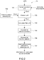
- Fig. 2 is a block diagram showing a configuration of the above-mentioned signal processing unit 15.
- the signal processing unit 15 includes a Fourier transform unit 151, an antenna pattern signal retaining unit 152, a division unit 153, a low-pass filter unit 154, an exponential function extractor 155, an exponential function selector 156, and a radio wave source information obtaining unit 157.
- the Fourier transform unit 151 calculates an azimuth frequency signal E( ⁇ ) by performing a Fourier transform with respect to the azimuthal angle on a square root signal e( ⁇ ) of a received electric power signal which has been input.
- ⁇ denotes an azimuthal angle
- ⁇ denotes an azimuth frequency.
- the antenna pattern signal retaining unit 152 retains an azimuth frequency signal G( ⁇ ) obtained by performing a Fourier transform with respect to the azimuthal angle on a square root signal g( ⁇ ) of an antenna electric power pattern to be used in a radar apparatus of the beam antenna 111.
- the division unit 153 divides the azimuth frequency signal E( ⁇ ) by the azimuth frequency signal G( ⁇ ).
- the low-pass filter unit 154 performs low-pass filtering on the output signals from the division unit 153.
- the azimuth frequency band is limited physically in the signal obtained by performing a Fourier transform on the square root signal of the antenna electric power pattern, it cannot have components beyond the band.
- division signals radio wave source distribution azimuth frequency signals
- which are obtained by signal processing in the division unit 153 includes azimuth frequency components beyond the band. It is generated due to a difference between actual processing and ideal processing. If the signal which has the components beyond the band is used for processing at a subsequent stage, the signal would be deteriorated. Therefore, here, low-pass filtering is performed to remove the signal components beyond the band, so that the deterioration of the signal is prevented.
- the exponential function extractor 155 fits signals, which are obtained by dividing in the division unit 153 and subjected to low-pass filtering, with exponential functions of exp( ⁇ i - j ⁇ i ) including the real part ⁇ i and the imaginary part j ⁇ i in the argument by using Prony's method.
- the exponential function selector 156 sets a threshold on the value of ⁇ i in advance and selects exponential functions with ⁇ i s equal to or smaller than the threshold (as radio wave source candidates).
- the radio wave source information obtaining unit 157 obtains radio wave source information from the exponential functions selected by the exponential function selector 156.
- the radio wave source information is a value of the relative intensity of each radio wave source candidate, the position (azimuthal angle), or the like.
- the transmitted electric power is supplied to the beam antenna 111 from the transmitter 12 and the radio waves are radiated from the beam antenna 111.
- the beam antenna 111 When the radio waves radiated from the beam antenna 111 are reflected on scatterers (targets) and are returned, the beam antenna 111 outputs the received radio waves.
- the received radio waves via the switch unit 14 are transformed into a square root signal of a received electric power signal by the receiver 13. Then, the transformed signal is input into the signal processing unit 15.
- the signal processing unit 15 the following signal processing is performed.
- the values of the relative intensity of each radio wave source candidate and the position (azimuthal angle) are displayed by the display unit 16.
- the display unit 16 displays the information in the form of a table or the like.
- Radio wave source information was reviewed in the case that an aperture antenna (antenna beam width: 1 degree) with uniform distribution whose length is 50.42 times as large as the wavelength was used as the antenna according to the present invention, radio waves were radiated by the antenna while rotating the antenna from -45 degrees to +45 degrees, and the radio waves which were scattered by identical point scatterers located in directions of -0.5 degrees and +0.5 degrees at an equal distance from the antenna and returned to the antenna were obtained in an environment where a signal-to-noise ratio was 20 dB.
- the low-pass filter passes signals within 0.8 (degrees -1 ), for example, with the absolute value in the azimuth frequency.
- F( ⁇ ) low-pass filtered is fit with the exponential functions including the real parts ⁇ i s and the imaginary parts j ⁇ i s in the arguments by using Prony's method.
- the exponential functions whose real parts ⁇ i are equal to or smaller than 0.01 as an absolute value are selected.
- the radio wave source information of the selected exponential functions and the real parts ⁇ i of the exponential function arguments are shown in Table 1 (information of top five radio wave source intensity).
- the radio wave sources with substantially the same intensity are located in two azimuth directions closer to the actual radio wave source positions. Although it is indicated that many radio wave sources exist in directions away from these directions, the intensity is lower by about 13 dB or more, and thus it can be determined as being caused by noise.
- the intensity of the radio wave sources obtained by the present invention is substantially the same as that obtained by Non-Patent Literature 1.
- the azimuth accuracy of the radio wave sources obtained by the present invention is lower than the azimuth accuracy of the radio wave sources obtained by Non-Patent Literature 1.
- the number of outputs not from the radio wave sources for the present invention is larger than that for Non-Patent Literature 1.
- the performance of obtaining the radio wave source information for the present invention becomes worse than that for the invention of Non-Patent Literature 1, but the azimuth accuracy is as high as the error which is 0.035 degrees at worst. It can be easily determined that the outputs not from the radio wave sources are caused by noise. Therefore, also in the present invention, the radio wave source information can be obtained with high accuracy.
- the antenna pattern signal retaining unit 152 retains an azimuth frequency signal G( ⁇ ) obtained by performing a Fourier transform with respect to the azimuthal angle on a square root signal g( ⁇ ) of an antenna electric power pattern to be used in a radar apparatus of the beam antenna 111, and the division unit 153 divides the azimuth frequency signal E( ⁇ ) by the azimuth frequency signal G( ⁇ ) and obtains an azimuth frequency signal F( ⁇ ).
- an antenna electric field pattern signal of the antenna may be used in place of the square root signal g( ⁇ ) of the antenna electric power pattern.
- the above-mentioned embodiment has been described as one using a mechanical antenna rotating device as means for moving a pointing direction of the antenna beam toward radio wave sources to be observed.
- an electronic antenna beam scanning means means for moving an antenna beam as mounted on a mobile platform such as an aircraft or satellite, or the like can be used as the means for moving the pointing direction of the antenna beam.
- the observation apparatus includes the antenna system, the display unit, and the like.
- the observation apparatus may be configured to be input with received electric power signals and angular signals from an external antenna system.
- the observation apparatus may be configured to output information to an external display apparatus and make the display apparatus display the information.
- the observation apparatus may perform predetermined determination processing on the basis of the radio wave source information obtained from the exponential functions without displaying the information.
- the antenna pattern signal retaining unit retains an azimuth frequency signal G( ⁇ ) obtained by performing a Fourier transform with respect to the azimuthal angle on a square root signal g( ⁇ ) of an antenna electric power pattern of the beam antenna.
- the square root signal g( ⁇ ) of the antenna electric power pattern of the beam antenna dynamically varies, the square root signal g( ⁇ ) may be configured to be input every time it varies, to thereby calculate the azimuth frequency signal G( ⁇ ).
- the threshold of the real part ⁇ i exemplified in the above-mentioned embodiment may be adaptively variable.
Landscapes
- Engineering & Computer Science (AREA)
- Radar, Positioning & Navigation (AREA)
- Remote Sensing (AREA)
- Computer Networks & Wireless Communication (AREA)
- Physics & Mathematics (AREA)
- General Physics & Mathematics (AREA)
- Radar Systems Or Details Thereof (AREA)
- Variable-Direction Aerials And Aerial Arrays (AREA)
Abstract
Description
- The present invention relates to an observation apparatus, an observation method, and a program to be used for observation by a radar, for example.
- For example, for observing objects to be observed at a radar, there is employed a method in which an antenna beam is rotated by rotation of an antenna or the like and intensity of electric power signals received at the antenna are simultaneously observed.
- At this time, radio wave source information (position (azimuthal angle), intensity) is generally determined by searching for the peak point of the received signals within the rotation range, which involves a problem that the radio wave source information cannot be directly extracted. The present inventor has proposed a method of directly determining radio wave source information by using a deconvolution method and Prony's method (see Patent Literature 1 and Non-Patent Literature 1). This method is a method of theoretically determining radio wave source information and it is confirmed by numerical simulation that the radio wave source information can be obtained.
- Patent Literature 1:
Japanese Patent Application Laid-open No. 2000-114850 - Non-Patent Literature 1: SEZAI, T. "Improvement of Direction Resolution of Rotational Radar by Prony Analysis of Deconvolved Antenna Output", Technical Report of The Institute of Electronics, Information and Communication Engineers (IEICE TECHNICAL REPORT) [ISSN: 0913-5685]. Volume 117, Number 182. 2017,08,17. Pages 37-42*Sections 2-4*
- The method proposed by the present inventor uses an electric field signal received by the antenna and an electric field pattern signal of the antenna. Since the electric field signal and the electric field pattern signal are complex number signals, it is necessary to obtain the amplitudes and phases of the electric field signals and the electric field pattern signals. In conventional observation apparatuses, the amplitude value is generally obtained, but the phase is not obtained in most cases.
- In the measurement of the antenna pattern, the measurement is often performed using a general-purpose facility, and thus it is not difficult to acquire the phase.
- In contrast to the above, for example, if the frequency of the radio wave arriving at the antenna is accurately known as in radars or communications, in order to obtain the phase of the electric field signals received by the antenna, it is necessary to modify a receiver of the observation apparatus and add a phase obtaining function thereto or to prepare a new receiver. For example, if the frequency of the radio wave arriving at the antenna is not accurately known as in the search for radio waves, in order to obtain the phase of the electric field signal received by the antenna, a reference antenna is installed adjacent to the antenna for the apparatus, and the phase is acquired with reference to the radio wave received by the reference antenna. Thus, there is a problem that the addition of the phase obtaining function makes the receiver or the entire apparatus complicated and increases dimensions, weight, and cost.
- In view of the above-mentioned circumstances, it is an object of the present invention to provide an observation apparatus, an observation method, and a program that are capable of directly obtaining radio wave source information by using a deconvolution method and Prony's method, without using the phase of an electric field signal received by an antenna.
- In order to solve the above-mentioned problem, an observation apparatus according to an embodiment of the present invention includes a signal processing unit that performs, using a square root signal of a received electric power signal from an antenna whose beam is scanned within a predetermined azimuthal angle range and a signal of an azimuthal angle of the scanned beam, a Fourier transform with respect to the azimuthal angle on the square root signal, divides a first azimuth frequency signal by a second azimuth frequency signal, the first azimuth frequency signal being obtained by performing the Fourier transform, the second azimuth frequency signal being obtained by performing a Fourier transform with respect to the azimuthal angle on a square root signal of an antenna electric power pattern or an antenna electric field pattern signal of the antenna, and fits the divided signal with exponential functions including real parts and imaginary parts in arguments by using Prony's method.
- A radio wave source distribution azimuth frequency function obtained in the course of the deconvolution processing is obtained by a Fourier transform with respect to the azimuthal angle on a distribution function of radio wave sources. It is possible to model the distribution of the radio wave sources in a case where it is the sum of a multiple of discrete radio wave sources. Each of the discrete radio wave sources can be considered as a point wave source, and thus its Fourier transform is represented by an exponential function whose amplitude is constant in the azimuth frequency. Therefore, the radio wave source distribution azimuth frequency function is represented as the sum of such exponential functions whose amplitude are constant.
- Thus, the information on the radio wave source distribution can be directly obtained by using the method disclosed in Patent Literature 1, i.e., by fitting the radio wave source distribution azimuth frequency function with exponential functions by using Prony's method. Further, when exponential function components are extracted from the radio wave source distribution azimuth frequency function by using the method disclosed in Non-Patent Literature 1, it is possible to discriminate the exponential functions by using the values of the real parts in the arguments and to exclude exponential functions caused by noise.
- The radio wave source distribution function is a function of the azimuthal angle, and the amplitude thereof is a complex number. However, phase information is rarely required during radio wave source observation. For this reason, even if the amplitude of the radio wave source distribution function is regarded as a real number and the result is obtained by the methods disclosed in Patent Literature 1 and Non-Patent Literature 1 using a square root signal of a received electric power signal from an antenna and a square root signal of an antenna electric power pattern or an antenna electric field pattern signal of the antenna, there is no problem practically.
- It is favorable that the signal processing unit extracts radio wave source candidates, whose absolute values of the real parts are equal to or smaller than a predetermined value, among radio wave source candidates obtained by the fitting.
- It is favorable that the signal processing unit obtains information for determining actual radio wave sources among the extracted radio wave source candidates from the exponential functions.
- It is more favorable that the information for determining the actual radio wave sources among the extracted radio wave source candidates includes values of relative amplitudes of the radio wave source candidates, values of the real parts, and values of the azimuthal angles.
- It is favorable that the observation apparatus according to the present invention further includes a display unit that displays information on the extracted radio wave source candidates and the information for determining the actual radio wave sources.
- It is favorable that the signal processing unit performs low-pass filtering on the divided signal before fitting by using Prony's method.
- It is favorable that the observation apparatus according to the present invention further includes one of antenna systems among an antenna system including a beam antenna with an antenna rotating device that rotates the beam antenna, an antenna system with an electronic antenna beam scan apparatus, and an antenna system including a beam antenna with an antenna movement apparatus that moves the beam antenna, as the antenna by which the beam is scanned within the predetermined azimuthal angle range.
- It is favorable that the observation apparatus according to the present invention further includes: a transmitter that supplies the antenna with transmitted electric power; and a switch unit that performs switching between transmitting and receiving.
- An observation method according to an embodiment of the present invention includes the steps of: performing, using a square root signal of a received electric power signal from an antenna whose beam is scanned within a predetermined azimuthal angle range and a signal of an azimuthal angle of the scanned beam, a Fourier transform with respect to the azimuthal angle on the square root signal of the received electric power signal; dividing a first azimuth frequency signal by a second azimuth frequency signal, the first azimuth frequency signal being obtained by performing the Fourier transform, the second azimuth frequency signal being obtained by performing a Fourier transform with respect to the azimuthal angle on a square root signal of an antenna electric power pattern or an antenna electric field pattern signal of the antenna; and fitting the divided signal with exponential functions including real parts and imaginary parts in arguments by using Prony's method.
- A program according to an embodiment of the present invention causes a computer to execute the steps of: performing, using a square root signal of a received electric power signal from an antenna whose beam is scanned within a predetermined azimuthal angle range and a signal of an azimuthal angle of the scanned beam, a Fourier transform with respect to the azimuthal angle on the square root signal of the received electric power signal; dividing a first azimuth frequency signal by a second azimuth frequency signal, the first azimuth frequency signal being obtained by performing the Fourier transform, the second azimuth frequency signal being obtained by performing a Fourier transform with respect to the azimuthal angle on a square root signal of an antenna electric power pattern or an antenna electric field pattern signal of the antenna; and fitting the divided signal with exponential functions including real parts and imaginary parts in arguments by using Prony's method. Advantageous Effects of Invention
- According to the present invention, it is possible to directly obtain radio wave source information by using a deconvolution method and Prony's method without using the phase of an electric field signal received by an antenna.
-
- [
Fig. 1] Fig. 1 is a block diagram showing an observation apparatus according to an embodiment of the present invention. - [
Fig. 2] Fig. 2 is a block diagram showing a configuration of a signal processing unit of the observation apparatus shown inFig. 1 . - [
Fig. 3] Fig. 3 is a graph showing an example of simulation results of radio wave source information according to the embodiment of the present invention. - [
Fig. 4] Fig. 4 is a graph showing an example of simulation results of radio wave source information according to a method shown in Non-Patent Literature 1. Mode(s) for Carrying Out the Invention - Hereinafter, an embodiment of the present invention will be described with reference to the drawings.
-
Fig. 1 is a block diagram showing an observation apparatus according to the embodiment of the present invention. In this embodiment, the observation apparatus according to the present invention is applied to a radar apparatus. - As shown in
Fig. 1 , anobservation apparatus 10 includes anantenna system 11, atransmitter 12, areceiver 13, aswitch unit 14, asignal processing unit 15, and adisplay unit 16. - The
observation apparatus 10 is a radar apparatus. Theobservation apparatus 10 is an apparatus that radiates radio waves toward targets and observes reflected waves thereof to thereby measure radio wave source information of the targets. - The
antenna system 11 scans an antenna beam within a predetermined azimuthal angle range. Theantenna system 11 includes abeam antenna 111 and anantenna rotation apparatus 112 that rotates thebeam antenna 111. Theantenna rotation apparatus 112 rotates thebeam antenna 111 in a direction in which the resolution of thebeam antenna 111 is to be improved. Theantenna system 11 outputs a signal of an azimuthal angle of a beam scanned according to rotation of theantenna rotation apparatus 112. Any antenna including a dipole-based antenna, a horn antenna, a parabolic antenna, an array antenna, and the like can be used as the beam antenna. - The
transmitter 12 supplies thebeam antenna 111 with transmitted electric power. - The
receiver 13 transforms received electric power signals of thebeam antenna 111 into square root signals thereof. - The
switch unit 14 switches between transmitting and receiving. - The
signal processing unit 15 inputs the square root signals of the received electric power signals from thereceiver 13 and the signals of the azimuthal angle from theantenna system 11 via theswitch unit 14, performs predetermined signal processing, and outputs information regarding radio wave source candidates, the relative intensity thereof, and values of real parts of exponential function arguments, positions (azimuthal angles), and the like. The real parts are to be described later. - On the basis of the output from the
signal processing unit 15, thedisplay unit 16 displays information regarding the relative intensity, the azimuthal angles, and the like of the information regarding the relative intensity of the radio wave source candidates, the values of the real parts of the exponential function arguments, and the positions (azimuthal angles). -
Fig. 2 is a block diagram showing a configuration of the above-mentionedsignal processing unit 15. - As shown in
Fig. 2 , thesignal processing unit 15 includes aFourier transform unit 151, an antenna patternsignal retaining unit 152, adivision unit 153, a low-pass filter unit 154, anexponential function extractor 155, anexponential function selector 156, and a radio wave sourceinformation obtaining unit 157. - The
Fourier transform unit 151 calculates an azimuth frequency signal E(ω) by performing a Fourier transform with respect to the azimuthal angle on a square root signal e(θ) of a received electric power signal which has been input. Here, "θ" denotes an azimuthal angle and "ω" denotes an azimuth frequency. The antenna patternsignal retaining unit 152 retains an azimuth frequency signal G(ω) obtained by performing a Fourier transform with respect to the azimuthal angle on a square root signal g(θ) of an antenna electric power pattern to be used in a radar apparatus of thebeam antenna 111. - The
division unit 153 divides the azimuth frequency signal E(ω) by the azimuth frequency signal G(ω). The division value is an azimuth frequency signal F(ω) obtained by performing a Fourier transform with respect to the azimuthal angle on a radio wave source distribution. That is, thedivision unit 153 calculates
- The low-
pass filter unit 154 performs low-pass filtering on the output signals from thedivision unit 153. As the azimuth frequency band is limited physically in the signal obtained by performing a Fourier transform on the square root signal of the antenna electric power pattern, it cannot have components beyond the band. However, division signals (radio wave source distribution azimuth frequency signals) which are obtained by signal processing in thedivision unit 153 includes azimuth frequency components beyond the band. It is generated due to a difference between actual processing and ideal processing. If the signal which has the components beyond the band is used for processing at a subsequent stage, the signal would be deteriorated. Therefore, here, low-pass filtering is performed to remove the signal components beyond the band, so that the deterioration of the signal is prevented. - The
exponential function extractor 155 fits signals, which are obtained by dividing in thedivision unit 153 and subjected to low-pass filtering, with exponential functions of exp(αi - jθi) including the real part αi and the imaginary part jθi in the argument by using Prony's method. - The
exponential function selector 156 sets a threshold on the value of αi in advance and selects exponential functions with αis equal to or smaller than the threshold (as radio wave source candidates). - The radio wave source
information obtaining unit 157 obtains radio wave source information from the exponential functions selected by theexponential function selector 156. The radio wave source information is a value of the relative intensity of each radio wave source candidate, the position (azimuthal angle), or the like. - Next, an operation of the
observation apparatus 10 thus configured will be described. - While the
beam antenna 111 is being rotated by theantenna rotation apparatus 112, the transmitted electric power is supplied to thebeam antenna 111 from thetransmitter 12 and the radio waves are radiated from thebeam antenna 111. - When the radio waves radiated from the
beam antenna 111 are reflected on scatterers (targets) and are returned, thebeam antenna 111 outputs the received radio waves. The received radio waves via theswitch unit 14 are transformed into a square root signal of a received electric power signal by thereceiver 13. Then, the transformed signal is input into thesignal processing unit 15. - In the
signal processing unit 15, the following signal processing is performed. - Calculate the azimuth frequency signal E(ω) obtained by performing a Fourier transform with respect to the azimuthal angle on the square root signal e(θ) of the received electric power signal.
- Divide this azimuth frequency signal E(ω) by the azimuth frequency signal G(ω) obtained by performing a Fourier transform with respect to the azimuthal angle on the square root signal g(θ) of the antenna electric power pattern in a radar apparatus of the
beam antenna 111. - Perform low-pass filtering on the division signal.
- Fit the signal, on which low-pass filtering is performed, with exponential functions including the real parts αis and the imaginary parts jθis in the arguments by using Prony's method.
- Set the value of αi for the threshold in advance and select the exponential functions of αi equal to or smaller than the threshold (as radio wave source candidate).
- Obtain the radio wave source information from the selected exponential function.
- The values of the relative intensity of each radio wave source candidate and the position (azimuthal angle) are displayed by the
display unit 16. Thedisplay unit 16 displays the information in the form of a table or the like. - Next, results of numerical simulation performed for confirming the effects according to the present invention will be described.
- Radio wave source information was reviewed in the case that an aperture antenna (antenna beam width: 1 degree) with uniform distribution whose length is 50.42 times as large as the wavelength was used as the antenna according to the present invention, radio waves were radiated by the antenna while rotating the antenna from -45 degrees to +45 degrees, and the radio waves which were scattered by identical point scatterers located in directions of -0.5 degrees and +0.5 degrees at an equal distance from the antenna and returned to the antenna were obtained in an environment where a signal-to-noise ratio was 20 dB.
- The low-pass filter passes signals within 0.8 (degrees-1), for example, with the absolute value in the azimuth frequency.
- F(ω) low-pass filtered is fit with the exponential functions including the real parts αis and the imaginary parts jθis in the arguments by using Prony's method.
The exponential functions whose real parts αi are equal to or smaller than 0.01 as an absolute value are selected. The radio wave source information of the selected exponential functions and the real parts αi of the exponential function arguments are shown in Table 1 (information of top five radio wave source intensity).[Table 1] Relative Relative intensity Relative intensity [dB] αi Azimuth [deg] 1 1.000 0.000 -0.0016 -0.535 2 0.841 -0.752 -0.0030 0.487 3 0.038 -14.249 -0.0072 -2.038 4 0.031 -15.079 0.0003 -30.003 5 0.031 -15.133 0.0004 33.873 - In addition, results showing the radio wave source information obtained by the simulation are shown in
Fig. 3 . - Thus, it can be seen from the radio wave source information obtained in accordance with the present invention that the radio wave sources with substantially the same intensity are located in two azimuth directions closer to the actual radio wave source positions. Although it is indicated that many radio wave sources exist in directions away from these directions, the intensity is lower by about 13 dB or more, and thus it can be determined as being caused by noise.
- As a comparative example, results obtained by the method shown in Non-Patent Literature 1 in the same manner as the above-mentioned numerical simulation are shown in Table 2 and
Fig. 4 .[Table 2] Relative intensity Relative intensity [dB] αi Azimuth [deg] 1 1.000 0.000 0.0001 -0.485 2 0.843 -0.742 0.0001 0.496 3 0.032 -14.900 0.0075 -26.308 4 0.029 -15.440 0.0048 -14.179 5 0.020 -17.020 -0.0043 1.979 - In comparison between Tables 1 and 2, the intensity of the radio wave sources obtained by the present invention is substantially the same as that obtained by Non-Patent Literature 1. The azimuth accuracy of the radio wave sources obtained by the present invention is lower than the azimuth accuracy of the radio wave sources obtained by Non-Patent Literature 1. In comparison between
Figs. 3 and 4 , the number of outputs not from the radio wave sources for the present invention is larger than that for Non-Patent Literature 1. As described above, in comparison with Non-Patent Literature 1, the performance of obtaining the radio wave source information for the present invention becomes worse than that for the invention of Non-Patent Literature 1, but the azimuth accuracy is as high as the error which is 0.035 degrees at worst. It can be easily determined that the outputs not from the radio wave sources are caused by noise. Therefore, also in the present invention, the radio wave source information can be obtained with high accuracy. - The present invention is not limited to the above-mentioned embodiment, various modifications can be made, and those fall within the range of the technical ideas of the present invention.
- In the above-mentioned embodiment, the antenna pattern
signal retaining unit 152 retains an azimuth frequency signal G(ω) obtained by performing a Fourier transform with respect to the azimuthal angle on a square root signal g(θ) of an antenna electric power pattern to be used in a radar apparatus of thebeam antenna 111, and thedivision unit 153 divides the azimuth frequency signal E(ω) by the azimuth frequency signal G(ω) and obtains an azimuth frequency signal F(ω). In the present invention, an antenna electric field pattern signal of the antenna may be used in place of the square root signal g(θ) of the antenna electric power pattern. - The above-mentioned embodiment has been described as one using a mechanical antenna rotating device as means for moving a pointing direction of the antenna beam toward radio wave sources to be observed. Alternatively, an electronic antenna beam scanning means, means for moving an antenna beam as mounted on a mobile platform such as an aircraft or satellite, or the like can be used as the means for moving the pointing direction of the antenna beam.
- Further, in the above-mentioned embodiment, the observation apparatus includes the antenna system, the display unit, and the like. Alternatively, the observation apparatus may be configured to be input with received electric power signals and angular signals from an external antenna system. Further, the observation apparatus may be configured to output information to an external display apparatus and make the display apparatus display the information. Alternatively, the observation apparatus may perform predetermined determination processing on the basis of the radio wave source information obtained from the exponential functions without displaying the information.
- Further, in the above-mentioned embodiment, the antenna pattern signal retaining unit retains an azimuth frequency signal G(ω) obtained by performing a Fourier transform with respect to the azimuthal angle on a square root signal g(θ) of an antenna electric power pattern of the beam antenna. However, in a case where the square root signal g(θ) of the antenna electric power pattern of the beam antenna dynamically varies, the square root signal g(θ) may be configured to be input every time it varies, to thereby calculate the azimuth frequency signal G(ω).
- The threshold of the real part αi exemplified in the above-mentioned embodiment may be adaptively variable.
-
- 10
- observation apparatus
- 11
- antenna system
- 12
- transmitter
- 13
- receiver
- 14
- switch unit
- 15
- signal processing unit
- 16
- display unit
- 151
- Fourier transform unit
- 152
- antenna pattern signal retaining unit
- 153
- division unit
- 154
- low-pass filter unit
- 155
- exponential function extractor
- 156
- exponential function selector
- 157
- radio wave source information obtaining unit
Claims (10)
- An observation apparatus, comprising
a signal processing unit thatperforms, using a square root signal of a received electric power signal from an antenna whose beam is scanned within a predetermined azimuthal angle range and a signal of an azimuthal angle of the scanned beam, a Fourier transform with respect to the azimuthal angle on the square root signal,divides a first azimuth frequency signal by a second azimuth frequency signal, the first azimuth frequency signal being obtained by performing the Fourier transform, the second azimuth frequency signal being obtained by performing a Fourier transform with respect to the azimuthal angle on a square root signal of an antenna electric power pattern or an antenna electric field pattern signal of the antenna, andfits the divided signal with exponential functions including real parts and imaginary parts in arguments by using Prony's method. - The observation apparatus according to claim 1, wherein
the signal processing unit extracts radio wave source candidates, whose absolute values of the real parts are equal to or smaller than a predetermined value, among radio wave source candidates obtained by the fitting. - The observation apparatus according to claim 2, wherein
the signal processing unit obtains information for determining actual radio wave sources among the extracted radio wave source candidates from the exponential functions. - The observation apparatus according to claim 3, wherein
the information for determining the actual radio wave sources among the extracted radio wave source candidates includes values of relative amplitudes of the radio wave source candidates, values of the real parts, and values of the azimuthal angles. - The observation apparatus according to claim 3 or 4, further comprising
a display unit that displays information on the extracted radio wave source candidates and the information for determining the actual radio wave sources. - The observation apparatus according to any one of claims 1 to 5, wherein
the signal processing unit performs low-pass filtering on the divided signal before fitting by using Prony's method. - The observation apparatus according to any one of claims 1 to 6, further comprising
one of antenna systems among an antenna system including a beam antenna with an antenna rotating device that rotates the beam antenna, an antenna system with an electronic antenna beam scan apparatus, and an antenna system including a beam antenna with an antenna movement apparatus that moves the beam antenna, as the antenna by which the beam is scanned within the predetermined azimuthal angle range. - The observation apparatus according to any one of claims 1 to 7, further comprising:a transmitter that supplies the antenna with transmitted electric power; anda switch unit that performs switching between transmitting and receiving.
- An observation method, comprising the steps of:performing, using a square root signal of a received electric power signal from an antenna whose beam is scanned within a predetermined azimuthal angle range and a signal of an azimuthal angle of the scanned beam, a Fourier transform with respect to the azimuthal angle on the square root signal;dividing a first azimuth frequency signal by a second azimuth frequency signal, the first azimuth frequency signal being obtained by performing the Fourier transform, the second azimuth frequency signal being obtained by performing a Fourier transform with respect to the azimuthal angle on a square root signal of an antenna electric power pattern or an antenna electric field pattern signal of the antenna; andfitting the divided signal with exponential functions including real parts and imaginary parts in arguments by using Prony's method.
- A program that causes a computer to execute the steps of:performing, using a square root signal of a received electric power signal from an antenna whose beam is scanned within a predetermined azimuthal angle range and a signal of an azimuthal angle of the scanned beam, a Fourier transform with respect to the azimuthal angle on the square root signal of the received electric power signal;dividing a first azimuth frequency signal by a second azimuth frequency signal, the first azimuth frequency signal being obtained by performing the Fourier transform, the second azimuth frequency signal being obtained by performing a Fourier transform with respect to the azimuthal angle on a square root signal of an antenna electric power pattern or an antenna electric field pattern signal of the antenna; andfitting the divided signal with exponential functions including real parts and imaginary parts in arguments by using Prony's method.
Applications Claiming Priority (3)
| Application Number | Priority Date | Filing Date | Title |
|---|---|---|---|
| JP2018191298 | 2018-10-09 | ||
| JP2019022337A JP6797428B2 (en) | 2018-10-09 | 2019-02-12 | Observation equipment, observation methods and programs |
| PCT/JP2019/006289 WO2020075319A1 (en) | 2018-10-09 | 2019-02-20 | Observation device, observation method, and program |
Publications (2)
| Publication Number | Publication Date |
|---|---|
| EP3865893A1 true EP3865893A1 (en) | 2021-08-18 |
| EP3865893A4 EP3865893A4 (en) | 2022-08-03 |
Family
ID=70219666
Family Applications (1)
| Application Number | Title | Priority Date | Filing Date |
|---|---|---|---|
| EP19872108.6A Pending EP3865893A4 (en) | 2018-10-09 | 2019-02-20 | OBSERVATION DEVICE, OBSERVATION METHOD AND PROGRAM |
Country Status (2)
| Country | Link |
|---|---|
| EP (1) | EP3865893A4 (en) |
| JP (1) | JP6797428B2 (en) |
Family Cites Families (3)
| Publication number | Priority date | Publication date | Assignee | Title |
|---|---|---|---|---|
| CN101060509B (en) * | 2006-04-19 | 2011-12-21 | 株式会社日立国际电气 | Symbol timing detector and wireless terminal |
| JP6167644B2 (en) * | 2013-04-26 | 2017-07-26 | 住友電気工業株式会社 | Meteorological observation apparatus, meteorological observation program, and meteorological observation method |
| WO2018174172A1 (en) * | 2017-03-24 | 2018-09-27 | 国立研究開発法人宇宙航空研究開発機構 | Observation device, observation method, and program |
-
2019
- 2019-02-12 JP JP2019022337A patent/JP6797428B2/en active Active
- 2019-02-20 EP EP19872108.6A patent/EP3865893A4/en active Pending
Also Published As
| Publication number | Publication date |
|---|---|
| EP3865893A4 (en) | 2022-08-03 |
| JP2020060543A (en) | 2020-04-16 |
| JP6797428B2 (en) | 2020-12-09 |
Similar Documents
| Publication | Publication Date | Title |
|---|---|---|
| US10054668B2 (en) | Probabilistic signal, detection, and track processing architecture and system | |
| US11555879B2 (en) | Observation apparatus, observation method, and program | |
| EP3214460B1 (en) | Synthetic aperture radar device | |
| US10732273B2 (en) | Radar device for vehicle and method for estimating angle of target using same | |
| US20230152436A1 (en) | System and Method for Determining Angle of Arrival in a Radar Based Point Cloud Generation | |
| US11789112B2 (en) | Observation apparatus, observation method, and program | |
| US11520004B2 (en) | System and method for generating point cloud data in a radar based object detection | |
| KR20190040637A (en) | SYSTEM AND METHOD FOR ESTIMATING RADAR DoA | |
| Chetty et al. | Data processing for real-time wireless passive radar | |
| US6392594B1 (en) | Radio wave receiving apparatus having an improved antenna resolution | |
| JP4200877B2 (en) | Moving target detection radar test equipment | |
| JP6797428B2 (en) | Observation equipment, observation methods and programs | |
| CN112731304A (en) | Arc array radar clutter suppression method based on azimuth angle domain filtering | |
| Ataman et al. | Eliminating range migration error in mm-wave radars for angle of arrival estimation | |
| JP3783502B2 (en) | Radar signal processing device | |
| JPWO2016199216A1 (en) | Passive radar device | |
| JP2002014160A (en) | Radar apparatus | |
| US6204809B1 (en) | Radio wave receiving apparatus having an improved antenna resolution | |
| Codau et al. | Implementation of an SDR-based FMCW Radar Receiver using LabVIEW NXG | |
| EP0990920B1 (en) | Radio wave source information display apparatus | |
| Lin et al. | Human tracking using a two-element antenna array | |
| RU2319168C1 (en) | Device for compensating signals received through side directional lobes | |
| KR102507882B1 (en) | Near-field measurement system and near-field measurement method of determining wideband beam pattern | |
| JP2021047040A (en) | Radar device | |
| Gallardo et al. | Development and Characterization of a 2D, 700-2600 MHz Receiver Array, for the Estimation of Direction of Arrival (DoA) in the Frequency Domain |
Legal Events
| Date | Code | Title | Description |
|---|---|---|---|
| STAA | Information on the status of an ep patent application or granted ep patent |
Free format text: STATUS: THE INTERNATIONAL PUBLICATION HAS BEEN MADE |
|
| PUAI | Public reference made under article 153(3) epc to a published international application that has entered the european phase |
Free format text: ORIGINAL CODE: 0009012 |
|
| STAA | Information on the status of an ep patent application or granted ep patent |
Free format text: STATUS: REQUEST FOR EXAMINATION WAS MADE |
|
| 17P | Request for examination filed |
Effective date: 20210506 |
|
| AK | Designated contracting states |
Kind code of ref document: A1 Designated state(s): AL AT BE BG CH CY CZ DE DK EE ES FI FR GB GR HR HU IE IS IT LI LT LU LV MC MK MT NL NO PL PT RO RS SE SI SK SM TR |
|
| DAV | Request for validation of the european patent (deleted) | ||
| DAX | Request for extension of the european patent (deleted) | ||
| A4 | Supplementary search report drawn up and despatched |
Effective date: 20220705 |
|
| RIC1 | Information provided on ipc code assigned before grant |
Ipc: G01S 7/292 20060101ALI20220629BHEP Ipc: G01S 7/02 20060101ALI20220629BHEP Ipc: G01S 3/58 20060101AFI20220629BHEP |
|
| STAA | Information on the status of an ep patent application or granted ep patent |
Free format text: STATUS: EXAMINATION IS IN PROGRESS |
|
| 17Q | First examination report despatched |
Effective date: 20250103 |