EP3865796A1 - Shelf assembly with specific front shelf as well as household cooling appliance - Google Patents
Shelf assembly with specific front shelf as well as household cooling appliance Download PDFInfo
- Publication number
- EP3865796A1 EP3865796A1 EP21151728.9A EP21151728A EP3865796A1 EP 3865796 A1 EP3865796 A1 EP 3865796A1 EP 21151728 A EP21151728 A EP 21151728A EP 3865796 A1 EP3865796 A1 EP 3865796A1
- Authority
- EP
- European Patent Office
- Prior art keywords
- shelf
- guiding
- assembly
- side bar
- ons
- Prior art date
- Legal status (The legal status is an assumption and is not a legal conclusion. Google has not performed a legal analysis and makes no representation as to the accuracy of the status listed.)
- Granted
Links
Images




Classifications
-
- F—MECHANICAL ENGINEERING; LIGHTING; HEATING; WEAPONS; BLASTING
- F25—REFRIGERATION OR COOLING; COMBINED HEATING AND REFRIGERATION SYSTEMS; HEAT PUMP SYSTEMS; MANUFACTURE OR STORAGE OF ICE; LIQUEFACTION SOLIDIFICATION OF GASES
- F25D—REFRIGERATORS; COLD ROOMS; ICE-BOXES; COOLING OR FREEZING APPARATUS NOT OTHERWISE PROVIDED FOR
- F25D25/00—Charging, supporting, and discharging the articles to be cooled
- F25D25/02—Charging, supporting, and discharging the articles to be cooled by shelves
-
- F—MECHANICAL ENGINEERING; LIGHTING; HEATING; WEAPONS; BLASTING
- F25—REFRIGERATION OR COOLING; COMBINED HEATING AND REFRIGERATION SYSTEMS; HEAT PUMP SYSTEMS; MANUFACTURE OR STORAGE OF ICE; LIQUEFACTION SOLIDIFICATION OF GASES
- F25D—REFRIGERATORS; COLD ROOMS; ICE-BOXES; COOLING OR FREEZING APPARATUS NOT OTHERWISE PROVIDED FOR
- F25D25/00—Charging, supporting, and discharging the articles to be cooled
- F25D25/02—Charging, supporting, and discharging the articles to be cooled by shelves
- F25D25/024—Slidable shelves
-
- F—MECHANICAL ENGINEERING; LIGHTING; HEATING; WEAPONS; BLASTING
- F25—REFRIGERATION OR COOLING; COMBINED HEATING AND REFRIGERATION SYSTEMS; HEAT PUMP SYSTEMS; MANUFACTURE OR STORAGE OF ICE; LIQUEFACTION SOLIDIFICATION OF GASES
- F25D—REFRIGERATORS; COLD ROOMS; ICE-BOXES; COOLING OR FREEZING APPARATUS NOT OTHERWISE PROVIDED FOR
- F25D2325/00—Charging, supporting or discharging the articles to be cooled, not provided for in other groups of this subclass
- F25D2325/021—Shelves with several possible configurations
Definitions
- An aspect of the invention relates to a shelf assembly for a household cooling appliance.
- a further aspect of the invention relates to a household cooling appliance.
- a shelf assembly is known.
- This assembly comprises two glass plates, which are each surrounded by a frame.
- the two plates are shiftable relative to each other in depth direction of the assembly.
- the assembly comprises a frame, by which these two plates are held.
- the frame only extends over the length of the rear plate with its side bars.
- the front plate is protruding forwards beyond the side bars in a use position.
- the front plate freely cantilevers at the front. Thereby, this front plate is severely loaded in the use position. Large leverage forces act on the mechanical connection of this front plate to the frame.
- holding brackets are a constituent of this carrying frame. However, these holding brackets are arranged virtually completely exposed. Thereby, functional impairments can result.
- the attachment to and mounting on the remaining components of the carrying frame are restricted. The entire mechanical stability of the carrying frame is thereby reduced.
- a shelf assembly is also known from US 9 127 877 B2 .
- two separate shelves are provided.
- One of these two shelves is movably arranged on a carrying frame of this assembly.
- the front, movable shelf comprises laterally protruding pins. These pins serve for coupling to a guiding formed at the carrying frame. Both in the rear area of this front shelf and in the front area, correspondingly protruding pins are respectively formed.
- the operability in this respect is to be improved for a movable shelf of this shelf assembly.
- An aspect of the invention relates to a shelf assembly for installation in a household cooling appliance, comprising:
- a further aspect of the invention relates to a household cooling appliance comprising: a housing,
- a household cooling appliance 1 is shown in a simplified representation.
- the household cooling appliance 1 is formed for storing and preserving food.
- the household cooling appliance 1 can for example be a cooling appliance or a freezing appliance or a fridge-freezing appliance.
- the household cooling appliance 1 comprises a housing 2.
- the housing 2 comprises an outer housing 3.
- the housing 2 comprises an inner liner 4.
- the inner liner 4 is received in the outer housing 3.
- the inner liner 4 is separate from the outer housing 3.
- the household cooling appliance 1 comprises at least one receiving space 5 for food. Multiple separate receiving spaces can also be provided.
- the receiving space 5 can be a cooling compartment. The receiving space 5 is bounded by walls of the inner liner 4.
- a thermally insulating material is arranged in a clearance 6 between the outer housing 3 and the inner liner 4.
- the household cooling appliance 1 comprises a door 7.
- the door 7 is movably arranged at the housing 2.
- the door 7 is pivotable around an axis A oriented in vertical direction (y-direction).
- the receiving space 5 is closable on the front side by the door 7.
- FIG. 1 An embodiment of a shelf assembly 8 is shown in a schematic representation in fig. 1 .
- the shelf assembly 8 is illustrated in its final position in the receiving space 5 in fig. 1 .
- the shelf assembly 8 can be removed from the receiving space 5 in non-destructively detachable manner.
- the shelf assembly 8 extends across the entire width of the receiving space 5. This width is measured in width direction (x-direction) of the household cooling appliance 1.
- the shelf assembly 8 extends over at least 50 percent of the depth of the receiving space 5. The depth is measured in depth direction (z-direction) of the household cooling appliance 1. In an embodiment, this shelf assembly 8 extends over at least 60 percent, in particular at least 70 percent, in particular at least 80 percent, in particular at least 90 percent of this depth of the receiving space 5.
- the shelf assembly 8 can be arranged at different discrete levels in the receiving space 5.
- the shelf assembly 8 can be used as a compartment divider or compartment shelf. In an embodiment, the shelf assembly 8 also serves for depositing storage goods. Such storage goods are food like beverages or meal.
- the shelf assembly 8 comprises a first shelf 9.
- the first shelf 9 comprises a base plate 10.
- the base plate 10 can for example be of glass. However, it can for example also be of plastic.
- the base plate 10 is quadrangular in the embodiment. In particular, it is rectangular.
- the first shelf 9 comprises a rear edge profile 11.
- the designation with respect to the rear edge profile 11 relates to the position at the first shelf 9 to other components of the first shelf 9 viewed in depth direction.
- This rear edge profile 11 is a rectilinear ledge. It is in particular C-shaped or U-shaped in cross-section.
- the edge profile 11 is formed without interruption.
- the rear edge profile 11 extends across the entire width of the base plate 10. This width is measured in width direction.
- the rear edge profile 11 is a component separate from the base plate 10 in an embodiment.
- the first shelf 9 comprises a front edge profile 12.
- the front edge profile 12 is formed as a rectilinear ledge. It can be U-shaped or C-shaped in cross-section.
- the front edge profile 12 is formed as a respectively separate component from the base plate 10 like the rear edge profile 11.
- the rear edge profile 10 can be fitted to the base plate 10.
- the front edge profile 12 can be fitted to the base plate 10.
- the rear edge profile 11 can be integrally formed of plastic. However, it can for example also be formed of metal.
- the front edge profile 12 can be integrally formed of plastic in an embodiment. However, it can also be formed of metal.
- this shelf assembly 8 comprises a second shelf 13.
- the second shelf 13 is formed separate from the first shelf 9 in an embodiment.
- the second shelf 13 comprises a base plate 14.
- the base plate 14 is for example formed of glass. However, it can also be formed of plastic. Similarly as the base plate 10, the base plate 14 can also be formed transparent at least in certain areas in an embodiment.
- the second shelf 13 can comprise a front edge profile 15.
- the front edge profile 15 is separate from the base plate 14.
- the front edge profile 15 extends across the entire width of the base plate 14.
- the front edge profile 15 can be C-shaped or U-shaped in cross-section.
- the front edge profile 15 is arranged at a front edge of the base plate 14. It can be fitted thereto.
- the shelf assembly 8 comprises a carrier frame 16.
- the carrier frame 16 is separate from the first shelf 9 and separate from the second shelf 13.
- the carrier frame 16 is U-shaped formed. In an embodiment, it comprises a first side bar 17. Moreover, it comprises a second side bar 18.
- the two side bars 17 and 18 extend in depth direction.
- the two side bars 17 and 18 are arranged parallel and spaced from each other.
- the two side bars 17 and 18 extend in depth direction. They are straight and bar-like.
- the carrier frame 16 comprises a connecting bar 19. It connects the two side bars 17 and 18.
- the second shelf 13 is the rear shelf in depth direction.
- This second shelf 13 is fixedly attached to the carrier frame 16 in an embodiment. In an embodiment, it can for example be adhered to the carrier frame 16.
- only a front edge 20 of the base plate 14 is provided with such a front edge profile 15.
- Side edges 21 and 22 of the base plate 14 are not provided with further such separate edge profiles in the shown embodiment.
- a rear edge 23 of the base plate 14 is not provided with such an edge profile in the shown embodiment.
- the base plate 14 and thus the second shelf 13 have a width, which exactly corresponds to the distance between the two side bars 17 and 18. Thereby, a lateral protrusion of the second shelf 13 viewed in width direction beyond these side bars 17 and 18 is avoided.
- the side edges 21 and 22 are arranged aligned to the outer sides of the side bars 17 and 18.
- a use position of the shelves 9 and 13 is shown.
- the first shelf 9 is arranged movable to the second shelf 13. In the state, in which it is arranged at the carrier frame 16, it can be shifted relative to the second shelf 13 at the carrier frame 16. In an embodiment, thereto, it can be shifted rearwards and below the second shelf 13 starting from the use position shown in fig. 2 . This is shown in fig. 3 . Thus, a non-use position of the first shelf 9 is shown there.
- the first shelf 9 can be positioned completely below the second shelf 13 viewed in depth direction. Thereby, a free space is formed between the side bars 17 and 18 in the non-use position of the shelf 9 shown in fig. 3 . Thereby, storage goods can be positioned in the receiving space 5 below the shelf assembly 8, but which nevertheless extend into this free space 24, as it is shown in fig. 3 , in vertical direction. Thereby, storage goods can also be positioned such that they can virtually extend upwards through the shelf assembly 8.
- the first shelf 9 is narrower in width direction than the second shelf 13 in an embodiment.
- the first shelf 9 is arranged flush with a top face 30 of the second shelf 13 with a top face 29 when the use position of the shelves 9 and 13 shown in fig. 2 is set.
- a guiding 31 is also illustrated.
- the guiding 31 is arranged at the first side bar 17 as well as at the second side bar 18.
- the guiding 31 comprises a first guiding part 31a ( fig. 4 ). It is arranged at the first side bar 17.
- a second guiding part of the guiding 31 is arranged at the second side bar 18.
- the movably supported first shelf 9 can be guided in defined manner by the guiding 31. In this context, it can be shifted in depth direction.
- the first side bar 17 of the carrier frame 16 is shown in an exploded representation.
- the first side bar 17 comprises a housing 32.
- the housing 32 comprises a first housing part 33.
- it comprises a second housing part 34 separate from the first housing part 33.
- the two housing parts 33 and 34 are elongated components. In an embodiment, they are each integrally formed. In this respect, they can for example be formed of plastic.
- the first guiding part 31a is arranged on an outer side 34a of the second housing part 34.
- the two housing parts 33 and 34 are connected by a connection 35 ( fig. 3 ).
- this connection 35 is a mechanical connection. It can for example be a snap-fit connection.
- these two housing parts 33 and 34 are shown in the mounted final position. Thereby, they form the housing 32.
- the housing 32 In this mounted final position, the housing 32 is such that it is closed at a front end 36 in the direction of its length axis B ( fig. 3 ). In circumferential direction around the length axis B, the housing 32 is also completely closed.
- the housing 32 is open at a rear end 37. In this respect, it comprises an opening 38.
- a hollow space 39 is formed in the interior of the housing 32. This hollow space 39 is provided for receiving a separate holding bracket 40 as it is shown in fig. 4 .
- the holding bracket 40 is integrally formed. For example, it can be formed of metal.
- the holding bracket 40 is sword-like formed in an embodiment.
- it comprises an elongated, strip-shaped bracket part 41.
- This bracket part 41 is introduced, in particular completely introduced, into the hollow space 31 in the mounted final state.
- the holding bracket 40 comprises an end piece 42.
- This end piece 42 is a rear end 40a of the holding bracket 40.
- This end piece 42 is thickened with respect to the bracket part 41.
- the end piece 42 comprises holding hooks 43 and 44.
- the shelf assembly 8 can be detachably attached to a household appliance component of the household cooling appliance 1 by these holding hooks 43 and 44. In particular, it can be hooked into this household appliance component by these holding hooks 43 and 44.
- the household appliance component can be a rear wall. It can be the rear wall of the inner liner 4. However, it can also be a rear wall separate from it.
- this rear-side end piece 42 of the holding bracket 40 extends rearwards out of the housing 32.
- the corresponding holding bracket 40 is shown in fig. 2 and fig. 3 , which is arranged in the second side bar 18.
- the second side bar 18 is constructed corresponding to the first side bar 17 with respect to the housing 32 and thus the housing parts 33 and 34.
- a tunnel-like or channel-like or scabbard-like housing 32 is also formed.
- the holding bracket 40 is arranged at the carrier frame 16 circumferentially protected on the one hand.
- it can thereby also be arranged in mechanically improved manner.
- a more stable attachment of this separate holding bracket 40 to further components of the carrier frame 16 is in particular allowed.
- the holding bracket 40 is positionally fixed to the housing parts 33 and/or 34. Thereto, a detent can be provided.
- the holding bracket 40 can then be arranged in the housing 32 in positionally fixed manner at least in depth direction.
- Couplers 45 and/or 46 can be provided as the detent. They are formed at the holding bracket 40, in particular the bracket part 41, in the embodiment.
- Counter couplers, which then engage with these couplers 45 and 46, can be formed at the housing part 33 and/or at the housing part 34.
- connection 35 for example comprises latches 47 in an embodiment. They are only symbolically illustrated in fig. 4 . Both the number and the position can be manifold in this respect. These latches 47 can snap-fit to further latches formed at the second housing part 34. Thereby, a snap-fit connection is formed.
- the latches 47 can be first latches in this context. Further latches can be formed at the second housing part 34 as second latches.
- a mount for the holding bracket 40 is formed by the couplers 45 and 46 and the counter coupling elements 48.
- counter couplers 48 can for example be provided at the first housing part 33.
- both the number and the position are definitely not to be understood in restricting or conclusive manner.
- the housing 32 comprises a top face 49.
- This top face 49 comprises a first top face section 50 in an embodiment.
- it comprises a second top face section 51.
- the two top face sections 50 and 51 are extensive strips. They are oriented in series to each other in depth direction.
- the top face sections 50 and 51 are rectilinearly formed.
- the top face section 50 is formed consistently at a first level.
- the second top face section 51 is formed at a different level compared thereto. However, in an embodiment, the second top face section 51 is formed at a lower level than the first top face section 50.
- a step 52 is formed at a transition between the top face sections 50 and 51 adjoining to each other. It forms the offset at the junction between the two top face sections 50 and 51.
- the second shelf 13 is laid, in particular adhered, on the second top face section 51 from above.
- the second shelf 13 is also laid, in particular adhered, on the corresponding top face section of the housing of the side bar 18.
- This guiding part 31a comprises a strip-shaped guiding lay-on 53.
- This guiding part 31a as it is provided at the first side bar 17, is arranged exclusively at the second housing part 34 in the embodiment. It is in particular formed integrally with the second housing part 34.
- this strip-shaped guiding lay-on 53 is formed farther in the direction to the second side bar 18 viewed in width direction than the first housing part 33 extends in this respect.
- this strip-shaped guiding lay-on 53 extends farther in the direction to the second side bar 18 as also the top face 49 in width direction.
- the shelf 9 only has to extend between the side bars 17 and 18 and can still be securely held and guided by laying on this strip-shaped guiding lay-on 53.
- a guiding link open towards the top is thus virtually formed.
- the first shelf 9 is virtually exposed towards the top upon guiding on this strip-shaped guiding lay-on 53 viewed in the area without guiding pins 57a, 57b. It is not bounded or covered by a corresponding upper guiding lay-on opposing the strip-shaped guiding lay-on 53.
- this strip-shaped guiding lay-on 53 comprises a ramp 54 in addition to the strip-shaped base lay-on 53a in an embodiment.
- the first shelf 9 is continuously moved into a higher position by this ramp 54 upon shifting from its non-use position shown in fig. 3 shortly before reaching the use position according to fig. 2 .
- this strip-shaped guiding lay-on 53 comprises a then again horizontal section 55. It adjoins to the ramp 54 on the front side.
- the first shelf 9 rests on this section 55 in particular with its front edge profile 12.
- the guiding 31 comprises a further ramp 56 at its guiding part 31a.
- This ramp 56 is narrower than the front ramp 54 viewed in width direction.
- the second ramp 56 is also narrower than this strip-shaped base lay-on 53a.
- a guiding pin 57a ( fig. 5 and fig. 6 ) is guided on this further ramp 56.
- This guiding pin 57a is formed at the rear edge profile 11. It is laterally protruding beyond the base plate 10 in width direction.
- the first shelf 9 does not comprise further laterally protruding guiding pins any more except for these two rear guiding pins 57a and 57b.
- such guiding pins are not present in a front length half of the first shelf 9.
- the length of this first shelf 9 is measured in depth direction of the shelf assembly 8 in this context.
- this front edge profile 12 does not comprise such laterally protruding guiding pins in an embodiment.
- the base plate 10 also does not comprise such guiding pins.
- the first shelf 9 is only coupled to two such guiding pins 57a and 57b of the guiding 31 in particular formed in a rear length half of the first shelf 9 and laterally protruding in an embodiment.
- these guiding pins 57a and 57b are guided in this guiding part 31a and there then brought into a final position.
- the guiding pin 57a is introduced in a receiving core 58 shown in fig. 4 .
- the guiding pin 57a is then also held in this receiving core 58, which is a constituent of the first guiding part 31a.
- the receiving core 58 is arranged at a level, which corresponds to the level of the section 55. Thereby, the first shelf 9 is completely horizontally oriented in its use position according to fig. 2 .
- the receiving core 58 is formed, in particular integrally formed, in the second housing part 34 in the shown embodiment.
- the receiving core 58 can also be referred to as receiving box or receiving recess.
- the second side bar 18 is correspondingly formed.
- the further guiding pin 57b can be correspondingly guided and positioned.
- the corresponding further ramp 56 is also formed there.
- this strip-shaped guiding lay-on 53 is formed in front of the second shelf 13 viewed in depth direction.
- this strip-shaped guiding lay-on extends over at least 90 percent in the direction of the measured length of the first shelf 9 in the use position.
- the shelf 9 is also completely laterally bordered by the housing 32 over its entire length in its use position according to fig. 2 .
- a front area of the shelf 9 also rests on this strip-shaped guiding lay-on 53 in the use position of the first shelf 9.
- the ramp 54 and the section 55 are also associated with it.
- this strip-shaped guiding lay-on 53 as it extends and geometrically forms, is also allowed that the first shelf 9 is simpler to handle with respect to its shift. A more jamming-free and strutting-free shift is allowed.
- laterally protruding guiding pins are no longer required.
- the shelf 9 is therefore also movable relative to the carrier frame 16 at least in the front area in an embodiment. In this respect, it can be easily lifted.
- the guiding pins 57a and 57b form a rotational axis or pivot axis, around which the first shelf 9 can also be pivoted in the use position.
- easy lifting can in particular be effected.
- moving the first shelf 9 from its use position towards the non-use position according to fig. 3 is also facilitated.
- the initiation this shifting process is also simplified by this configuration. Because, the first shelf 9 can first be easily lifted on the front side starting from the use position shown in fig. 2 in this context. Thereby, the following shift of the first shelf 9 is simplified. Leading out the guiding pins 57a and 57b from the receiving core 58 is thereby facilitated.
- this first shelf 9 rests on these strip-shaped guiding lay-ons 53. In an embodiment, this is effected by the front edge profile 12. It can also be provided that the base plate 10 additionally directly rests on this strip-shaped guiding lay-on 53.
- this strip-shaped guiding lay-on 53 In the surface area of this strip-shaped guiding lay-on 53, the first shelf 9 is arranged completely exposed towards the top and thus viewed in vertical direction. This means, as it was already explained above, that this strip-shaped guiding lay-on 53 does not comprise an overlying counterpart such that an upwards closed guiding groove is not formed.
- a first length half L1 ( fig. 5 ) of the first shelf 9 is only guided by resting on this strip-shaped guiding lay-ons 53 of these two side bars 17 and 18.
- This front length half L1 does not comprise lateral guiding pins or the like as the rear length half L2 of the first shelf 9 comprises.
- the guiding 31 comprises a rear guiding section 59 in an embodiment.
- This rear guiding section 59 as it is illustrated at the side bar 17 in fig. 4 , is arranged below the second shelf 13 in vertical direction (y-direction) of the shelf assembly 8. Thereby, the first shelf 9 can be shifted below the second shelf 13 also guided in this respect.
- the rear guiding section 59 directly adjoins to the guiding lay-on 53.
- the rear guiding section 59 is a constituent of the first guiding part 31a.
- the first shelf 9 can be rearwards shifted out of the carrier frame 16 in depth direction of the shelf assembly 8.
- this first shelf 9 can be rearwards shifted out of the carrier frame 16. Thereby, it can also be completely removed from the carrier frame 16. Thereby, the cleanability of the first shelf 9 is for example separately possible. Improved cleaning of this component is thereby allowed.
- a partial section of the shelf assembly 8 according to fig. 2 is shown in a vertical sectional representation.
- the sectional plane is the y-z plane.
- the rear edge profile 11 comprises a rear wall 60.
- This rear wall 60 is obliquely oriented.
- An upper end 60a of this rear wall 60 is farther forward than a lower end 60b viewed in depth direction.
- a front wall 61 of the front edge profile 15 is obliquely inclined.
- an upper end 61a of this front wall 61 is positioned farther forward viewed in depth direction than a lower end 61b.
- the rear wall 60 and the front wall 61 are inclined in the same direction.
- a distance between this rear wall 60 and the front wall 61 is set in the use position.
- a crack 62 is formed. It can be configured relatively small in this respect. If such an inclined position of the rear wall 60 and/or the front wall 61 would not be formed, the crack 62 would be considerably larger measured in depth direction. This would be disadvantageous with regard to falling-through of storage parts or the like.
- a specific venting slit can then also be formed. The passage of the air can also be effected preset in a certain orientation to some extent by this specific inclination.
- the rear edge profile 11 is attached to the base plate 10 by a snap-fit connection 63.
- the front edge profile 15 is attached to the base plate 14 by a corresponding snap-fit connection.
- fig. 8 the arrangement of the components according to fig. 7 is shown in a corresponding vertical sectional representation. However, a vertical sectional plane different from fig. 7 is chosen in fig. 8 . It is parallel to fig. 7 . In fig. 8 , a vertical sectional representation through the guiding pin 57a is shown in this respect.
- the receiving core 58 is also shown in fig. 8 .
- the receiving core 58 is bounded towards the front by a front wall 64a.
- a stop for the guiding pin 57a is formed by the front wall 64a.
- the receiving core 58 is bounded towards the bottom by a base wall 64b.
- the guiding pin 57a rests on this base wall 64b in its final position when it is introduced in the receiving core 58.
- fig. 9 a representation of a partial section of the shelf assembly 8 according to fig. 2 is shown in a plan view.
- fig. 10 the shelf assembly 8 is shown in a further vertical sectional representation. In contrast to the representation in fig. 3 , in which the non-use position of the shelf 9 is illustrated, this shelf is already shifted out of the carrier frame 16 slightly further to the rear in fig. 10 . In this context, fig. 10 shows the possibility already set forth above of completely rearwards removing the shelf 9 out of the carrier frame 16.
- a front end 65 of the first side bar 17 of the carrier frame 16 is shown in fig. 10 as already apparent in fig. 3 and fig. 4 as well as also in fig. 2 .
- the front end 65 is formed tapered.
- the front end 65 comprises a neck 66 protruding to the front.
- This neck 66 has a thickness d.
- this thickness d corresponds to the thickness d1 ( fig. 5 ) of the first shelf 9.
- the thickness d1 is the thickness of the front edge profile 12.
- the second side bar 18 is also correspondingly configured.
- the base plate of the first shelf comprises a front edge
- the first shelf comprises a front edge profile, which is arranged at the front edge
- the base plate of the first shelf comprises a first side edge and an opposing second side edge, and an edge profile is not arranged at the two side edges and the two side edges are exposed.
- the guiding comprises rear guiding sections, which are formed at the side bars and are arranged below the second shelf in vertical direction of the shelf assembly such that the first shelf can be shifted below the second shelf and the first shelf can be rearwards shifted out of the carrier frame in depth direction of the shelf assembly.
- the rear edge profile comprises a rear wall, wherein the rear wall is arranged obliquely from the top to the bottom viewed in vertical direction of the shelf assembly.
- the second shelf comprises a front edge profile, wherein the front edge profile comprises a front wall, wherein the front wall is arranged obliquely from the bottom to the top viewed in vertical direction of the shelf assembly.
- front wall and the rear wall are spaced in a use position of the first shelf and the second shelf such that a crack inclined obliquely to the front viewed in cross-section is formed.
- the guiding comprises at least one receiving core, into which the guiding pin is introduced when the first shelf is arranged in a use position, wherein the first shelf is arranged completely in front of the second shelf in depth direction of the shelf assembly in this use position.
- the receiving core comprises a front wall, by which a stop for the guiding pin is formed, and a base wall, on which the guiding pin sits in its final position in the receiving core.
- the first side bar comprises a first holding bracket for holding the shelf assembly at a household cooling appliance component and the first side bar comprises a channel-like housing, into which the first holding bracket is introduced
- the second side bar comprises a second holding bracket for holding the shelf assembly at a household cooling appliance component and the second side bar comprises a channel-like housing, into which the second holding bracket is introduced.
- the first side bar comprises a top face
- the top face comprises a first top face section and a second top face section, wherein the top face sections are arranged at different levels and directly adjoin to each other, and the junction is a step
- the second side bar comprises a top face
- the top face comprises a first top face section and a second top face section, wherein the top face sections are arranged at different levels and directly adjoin to each other and the junction is a step.
- the second shelf rests on the second top face sections.
- the second shelf is adhered to the second top face section.
- the first side bar comprises a front end, wherein the front end is tapered, wherein the front end comprises a forward protruding neck, which has a thickness, which corresponds to the thickness of a front border of the first shelf
- the second side bar comprises a front end, wherein the front end is tapered, wherein the front end comprises a forward protruding neck, which has a thickness, which corresponds to the thickness of the front border of the first shelf.
Landscapes
- Engineering & Computer Science (AREA)
- Chemical & Material Sciences (AREA)
- Combustion & Propulsion (AREA)
- Physics & Mathematics (AREA)
- Mechanical Engineering (AREA)
- Thermal Sciences (AREA)
- General Engineering & Computer Science (AREA)
- Handcart (AREA)
- Assembled Shelves (AREA)
Abstract
Description
- An aspect of the invention relates to a shelf assembly for a household cooling appliance. A further aspect of the invention relates to a household cooling appliance.
- From
US 9 103 582 B2 - A shelf assembly is also known from
US 9 127 877 B2 - Furthermore, from
US 8 840 205 B2 a shelf assembly is known. The construction is corresponding as inUS 9 127 877 B2 - It is an object of the present invention to provide a shelf assembly, in which the carrier frame is improved. In particular, it is an object to more stably configure this carrier frame. It is an object to position holding brackets of the carrier frame in improved manner. In this respect, the stability of these holding brackets in particular is to be improved.
- It is an object of the invention to improve the operability of a shelf of the shelf assembly. The operability in this respect is to be improved for a movable shelf of this shelf assembly. In particular, it is an object to be able to more smoothly shift a movable shelf of the shelf assembly. Jammings and struttings of this movable shelf upon shifting at least are to be reduced. It is an object of the present invention to provide a movable shelf of the shelf assembly, which allows certain movability with respect to the carrier frame in the use position.
- It is a further object of the present invention to provide a household cooling appliance with such a shelf assembly.
- These objects are solved by a shelf assembly and a household cooling appliance according to the independent claims.
- An aspect of the invention relates to a shelf assembly for installation in a household cooling appliance, comprising:
- a first shelf, wherein the first shelf comprises a base plate, which comprises a rear edge, and the first shelf comprises a rear edge profile, which is arranged at the rear edge,
- a second shelf, which is separate from the first shelf,
- a carrier frame, at which the first shelf and the second shelf are arranged,
- wherein the carrier frame comprises a guiding, and at least the first shelf can be shifted relative to the carrier frame and to the other shelf in guided manner by the guiding,
- wherein the carrier frame comprises a first side bar and a second side bar, and the guiding is arranged at the first side bar and the second side bar, wherein
- the rear edge profile comprises at least one laterally protruding guiding pin, which is coupled to the guiding, and
- the guiding comprises strip-shaped guiding lay-ons, and the shelf assembly has a depth direction and a vertical direction, wherein the strip-shaped guiding lay-ons are arranged in front of the second shelf in this depth direction at the side bars, wherein
- the first shelf rests on the strip-shaped guiding lay-ons upon shifting the first shelf and the first shelf is arranged completely exposed to the top viewed in vertical direction of the shelf assembly in the surface area of the guiding lay-ons, wherein
- the first shelf has a front length half and the first length half is guided only by resting on the guiding lay-ons,
- wherein the guiding lay-ons extend over at least 90% of the length of the first shelf and this length is measured in depth direction of the shelf assembly.
- A further aspect of the invention relates to a household cooling appliance comprising:
a housing, - a receiving space for food, which is arranged in the housing,
- a shelf assembly, which is arranged in the receiving space, wherein the shelf assembly comprises:
- a first shelf, wherein the first shelf comprises a base plate, which comprises a rear edge, and the first shelf comprises a rear edge profile, which is arranged at the rear edge,
- a second shelf, which is separate from the first shelf,
- a carrier frame, at which the first shelf and the second shelf are arranged,
- wherein the carrier frame comprises a guiding, and at least the first shelf can be shifted relative to the carrier frame and to the other shelf in guided manner by the guiding,
- wherein the carrier frame comprises a first side bar and a second side bar, and the guiding is arranged at the first side bar and the second side bar, wherein
- the rear edge profile comprises at least one laterally protruding guiding pin, which is coupled to the guiding, and
- the guiding comprises strip-shaped guiding lay-ons, and the shelf assembly has a depth direction and a vertical direction, wherein the strip-shaped guiding lay-ons are arranged in front of the second shelf in this depth direction at the side bars, wherein
- the first shelf rests on the strip-shaped guiding lay-ons upon shifting the first shelf and the first shelf is arranged completely exposed to the top viewed in vertical direction of the shelf assembly in the surface area of the guiding lay-ons, wherein
- the first shelf has a front length half and the first length half is guided only by resting on the guiding lay-ons,
- wherein the guiding lay-ons extend over at least 90% of the length of the first shelf and this length is measured in depth direction of the shelf assembly.
- Further features of the invention are apparent from the claims, the figures and the description of figures. The features and feature combinations mentioned above in the description as well as the features and feature combinations mentioned below in the description of figures and/or shown in the figures alone are usable not only in the respectively specified combination, but also in other combinations without departing from the scope of the invention. Thus, implementations are also to be considered as encompassed and disclosed by the invention, which are not explicitly shown in the figures and explained, but arise from and can be generated by separated feature combinations from the explained implementations. Implementations and feature combinations are also to be considered as disclosed, which thus do not comprise all of the features of an originally formulated independent claim. Moreover, implementations and feature combinations are to be considered as disclosed, in particular by the implementations set out above, which extend beyond or deviate from the feature combinations set out in the back-references of the claims.
- Below, embodiments of the invention are explained in more detail based on schematic drawings. These show in:
- fig. 1
- a schematic perspective representation of an embodiment of a household cooling appliance according to the invention with a schematic representation of an embodiment of a shelf assembly according to the invention;
- fig. 2
- a perspective representation of an embodiment of a shelf assembly in a use position of two shelves of this shelf assembly;
- fig. 3
- the representation of the shelf assembly according to
fig. 2 in a stowage position of one of the two shelves; - fig. 4
- an exploded representation of partial components of a carrier frame of the shelf assembly according to
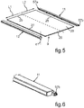
fig. 2 and fig. 3 ; - fig. 5
- an exploded representation of an embodiment of a shelf of the shelf assembly according to
fig. 2 and fig. 3 ; - fig. 6
- a perspective representation of a partial area of an edge profile of the shelf according to
fig. 5 ; - fig. 7
- a sectional representation through a partial area of the shelf assembly in the use position according to
fig. 2 ; - fig. 8
- a sectional representation according to
fig. 7 in a sectional plane parallel thereto; - fig. 9
- a plan view to a partial area of a shelf assembly according to
fig. 2 ; and - fig. 10
- a sectional representation through the shelf assembly according to
Fig. 2 and fig. 3 , wherein a movable shelf of this shelf assembly is rearwards guided out of a carrier frame of the shelf assembly in certain areas in the representation according tofig. 10 . - In the figures, identical or functionally identical parts are provided with the same reference signs.
- With indications of "top", "bottom", "front", "rear", "horizontal", "vertical", "depth direction", "width direction", "height direction", etc., the positions and orientations given in intended use and intended arrangement of the apparatus are specified.
- In
fig. 1 , a household cooling appliance 1 is shown in a simplified representation. The household cooling appliance 1 is formed for storing and preserving food. The household cooling appliance 1 can for example be a cooling appliance or a freezing appliance or a fridge-freezing appliance. The household cooling appliance 1 comprises ahousing 2. In an embodiment, thehousing 2 comprises an outer housing 3. Moreover, thehousing 2 comprises aninner liner 4. Theinner liner 4 is received in the outer housing 3. Theinner liner 4 is separate from the outer housing 3. - In an embodiment, the household cooling appliance 1 comprises at least one receiving
space 5 for food. Multiple separate receiving spaces can also be provided. In an embodiment, the receivingspace 5 can be a cooling compartment. The receivingspace 5 is bounded by walls of theinner liner 4. - In an embodiment, a thermally insulating material is arranged in a
clearance 6 between the outer housing 3 and theinner liner 4. - In an embodiment, the household cooling appliance 1 comprises a
door 7. In the shown embodiment, thedoor 7 is movably arranged at thehousing 2. In an embodiment, thedoor 7 is pivotable around an axis A oriented in vertical direction (y-direction). The receivingspace 5 is closable on the front side by thedoor 7. - Moreover, an embodiment of a
shelf assembly 8 is shown in a schematic representation infig. 1 . Theshelf assembly 8 is illustrated in its final position in the receivingspace 5 infig. 1 . Theshelf assembly 8 can be removed from the receivingspace 5 in non-destructively detachable manner. As is apparent, theshelf assembly 8 extends across the entire width of the receivingspace 5. This width is measured in width direction (x-direction) of the household cooling appliance 1. - In an embodiment, it is provided that the
shelf assembly 8 extends over at least 50 percent of the depth of the receivingspace 5. The depth is measured in depth direction (z-direction) of the household cooling appliance 1. In an embodiment, thisshelf assembly 8 extends over at least 60 percent, in particular at least 70 percent, in particular at least 80 percent, in particular at least 90 percent of this depth of the receivingspace 5. - In an embodiment, it can be provided that the
shelf assembly 8 can be arranged at different discrete levels in the receivingspace 5. - The
shelf assembly 8 can be used as a compartment divider or compartment shelf. In an embodiment, theshelf assembly 8 also serves for depositing storage goods. Such storage goods are food like beverages or meal. - In
fig. 2 , an embodiment of ashelf assembly 8 is shown in a perspective representation. Theshelf assembly 8 comprises afirst shelf 9. Thefirst shelf 9 comprises abase plate 10. Thebase plate 10 can for example be of glass. However, it can for example also be of plastic. Thebase plate 10 is quadrangular in the embodiment. In particular, it is rectangular. In the embodiment, thefirst shelf 9 comprises arear edge profile 11. The designation with respect to therear edge profile 11 relates to the position at thefirst shelf 9 to other components of thefirst shelf 9 viewed in depth direction. Thisrear edge profile 11 is a rectilinear ledge. It is in particular C-shaped or U-shaped in cross-section. In an embodiment, theedge profile 11 is formed without interruption. In an embodiment, therear edge profile 11 extends across the entire width of thebase plate 10. This width is measured in width direction. Therear edge profile 11 is a component separate from thebase plate 10 in an embodiment. - In an embodiment, the
first shelf 9 comprises afront edge profile 12. Thefront edge profile 12 is formed as a rectilinear ledge. It can be U-shaped or C-shaped in cross-section. In an embodiment, thefront edge profile 12 is formed as a respectively separate component from thebase plate 10 like therear edge profile 11. In an embodiment, therear edge profile 10 can be fitted to thebase plate 10. In an embodiment, thefront edge profile 12 can be fitted to thebase plate 10. In an embodiment, therear edge profile 11 can be integrally formed of plastic. However, it can for example also be formed of metal. Thefront edge profile 12 can be integrally formed of plastic in an embodiment. However, it can also be formed of metal. - In an embodiment, this
shelf assembly 8 comprises asecond shelf 13. Thesecond shelf 13 is formed separate from thefirst shelf 9 in an embodiment. In an embodiment, thesecond shelf 13 comprises abase plate 14. Thebase plate 14 is for example formed of glass. However, it can also be formed of plastic. Similarly as thebase plate 10, thebase plate 14 can also be formed transparent at least in certain areas in an embodiment. - In an embodiment, the
second shelf 13 can comprise afront edge profile 15. In an embodiment, thefront edge profile 15 is separate from thebase plate 14. In an embodiment, thefront edge profile 15 extends across the entire width of thebase plate 14. Thefront edge profile 15 can be C-shaped or U-shaped in cross-section. In an embodiment, thefront edge profile 15 is arranged at a front edge of thebase plate 14. It can be fitted thereto. - In an embodiment, the
shelf assembly 8 comprises acarrier frame 16. Thecarrier frame 16 is separate from thefirst shelf 9 and separate from thesecond shelf 13. In an embodiment, thecarrier frame 16 is U-shaped formed. In an embodiment, it comprises afirst side bar 17. Moreover, it comprises asecond side bar 18. The twoside bars side bars side bars - Moreover, the
carrier frame 16 comprises a connectingbar 19. It connects the twoside bars - In an embodiment, the
second shelf 13 is the rear shelf in depth direction. Thissecond shelf 13 is fixedly attached to thecarrier frame 16 in an embodiment. In an embodiment, it can for example be adhered to thecarrier frame 16. In the shown embodiment, only afront edge 20 of thebase plate 14 is provided with such afront edge profile 15. Side edges 21 and 22 of thebase plate 14 are not provided with further such separate edge profiles in the shown embodiment. Moreover, arear edge 23 of thebase plate 14 is not provided with such an edge profile in the shown embodiment. - In an embodiment, it is provided that the
base plate 14 and thus thesecond shelf 13 have a width, which exactly corresponds to the distance between the twoside bars second shelf 13 viewed in width direction beyond these side bars 17 and 18 is avoided. In particular, the side edges 21 and 22 are arranged aligned to the outer sides of the side bars 17 and 18. - In
fig. 2 , a use position of theshelves shelves shelf assembly 8 is formed. In an embodiment, thefirst shelf 9 is arranged movable to thesecond shelf 13. In the state, in which it is arranged at thecarrier frame 16, it can be shifted relative to thesecond shelf 13 at thecarrier frame 16. In an embodiment, thereto, it can be shifted rearwards and below thesecond shelf 13 starting from the use position shown infig. 2 . This is shown infig. 3 . Thus, a non-use position of thefirst shelf 9 is shown there. It can be provided that thefirst shelf 9 can be positioned completely below thesecond shelf 13 viewed in depth direction. Thereby, a free space is formed between the side bars 17 and 18 in the non-use position of theshelf 9 shown infig. 3 . Thereby, storage goods can be positioned in the receivingspace 5 below theshelf assembly 8, but which nevertheless extend into thisfree space 24, as it is shown infig. 3 , in vertical direction. Thereby, storage goods can also be positioned such that they can virtually extend upwards through theshelf assembly 8. - In the embodiment according to
fig. 2 and fig. 3 , it is provided that side edges 25 and 26 of thebase plate 10 of thefirst shelf 9 are formed without a frame fixedly arranged thereon. Thus, edge profiles are in particular not arranged at these side edges 25 and 26. In the shown embodiment, thus, only thefront edge 27 is provided with thefront edge profile 12 and arear edge 28 in therear edge profile 11. - Moreover, it is apparent that the
first shelf 9 is narrower in width direction than thesecond shelf 13 in an embodiment. In an embodiment, thefirst shelf 9 is arranged flush with atop face 30 of thesecond shelf 13 with atop face 29 when the use position of theshelves fig. 2 is set. - In
fig. 3 , an embodiment is shown, in which a guiding 31 is also illustrated. In an embodiment, the guiding 31 is arranged at thefirst side bar 17 as well as at thesecond side bar 18. Thereto, the guiding 31 comprises a first guidingpart 31a (fig. 4 ). It is arranged at thefirst side bar 17. A second guiding part of the guiding 31 is arranged at thesecond side bar 18. The movably supportedfirst shelf 9 can be guided in defined manner by the guiding 31. In this context, it can be shifted in depth direction. - In
fig. 4 , thefirst side bar 17 of thecarrier frame 16 is shown in an exploded representation. Thefirst side bar 17 comprises ahousing 32. In the shown embodiment, thehousing 32 comprises afirst housing part 33. Moreover, it comprises asecond housing part 34 separate from thefirst housing part 33. The twohousing parts first guiding part 31a is arranged on anouter side 34a of thesecond housing part 34. The twohousing parts fig. 3 ). In particular, thisconnection 35 is a mechanical connection. It can for example be a snap-fit connection. - In
fig. 3 , these twohousing parts housing 32. In this mounted final position, thehousing 32 is such that it is closed at afront end 36 in the direction of its length axis B (fig. 3 ). In circumferential direction around the length axis B, thehousing 32 is also completely closed. Thehousing 32 is open at arear end 37. In this respect, it comprises anopening 38. In the assembled state of the twohousing parts hollow space 39 is formed in the interior of thehousing 32. Thishollow space 39 is provided for receiving aseparate holding bracket 40 as it is shown infig. 4 . In an embodiment, the holdingbracket 40 is integrally formed. For example, it can be formed of metal. The holdingbracket 40 is sword-like formed in an embodiment. In this respect, it comprises an elongated, strip-shapedbracket part 41. Thisbracket part 41 is introduced, in particular completely introduced, into thehollow space 31 in the mounted final state. In an embodiment, the holdingbracket 40 comprises anend piece 42. Thisend piece 42 is arear end 40a of the holdingbracket 40. Thisend piece 42 is thickened with respect to thebracket part 41. In an embodiment, theend piece 42 comprises holdinghooks shelf assembly 8 can be detachably attached to a household appliance component of the household cooling appliance 1 by these holdinghooks hooks inner liner 4. However, it can also be a rear wall separate from it. - As it is apparent in
fig. 2 and fig. 3 , this rear-side end piece 42 of the holdingbracket 40 extends rearwards out of thehousing 32. In this respect, the corresponding holdingbracket 40 is shown infig. 2 and fig. 3 , which is arranged in thesecond side bar 18. Thesecond side bar 18 is constructed corresponding to thefirst side bar 17 with respect to thehousing 32 and thus thehousing parts - By the configuration of the
housing parts like housing 32 is also formed. By such a configuration, it is allowed that such an elongated, sword-like holding bracket 40 is introduced as extensively as possible. Thus, the holdingbracket 40 is arranged at thecarrier frame 16 circumferentially protected on the one hand. On the other hand, it can thereby also be arranged in mechanically improved manner. Thus, a more stable attachment of thisseparate holding bracket 40 to further components of thecarrier frame 16 is in particular allowed. In an embodiment, it can be provided that the holdingbracket 40 is positionally fixed to thehousing parts 33 and/or 34. Thereto, a detent can be provided. In this context, the holdingbracket 40 can then be arranged in thehousing 32 in positionally fixed manner at least in depth direction.Couplers 45 and/or 46 can be provided as the detent. They are formed at the holdingbracket 40, in particular thebracket part 41, in the embodiment. Counter couplers, which then engage with thesecouplers housing part 33 and/or at thehousing part 34. - In
fig. 4 , it is also shown in an embodiment that theconnection 35 for example compriseslatches 47 in an embodiment. They are only symbolically illustrated infig. 4 . Both the number and the position can be manifold in this respect. These latches 47 can snap-fit to further latches formed at thesecond housing part 34. Thereby, a snap-fit connection is formed. Thelatches 47 can be first latches in this context. Further latches can be formed at thesecond housing part 34 as second latches. - A mount for the holding
bracket 40 is formed by thecouplers counter coupling elements 48. In this embodiment,counter couplers 48 can for example be provided at thefirst housing part 33. Here too, both the number and the position are definitely not to be understood in restricting or conclusive manner. - In an embodiment, the
housing 32 comprises atop face 49. Thistop face 49 comprises a firsttop face section 50 in an embodiment. Moreover, it comprises a secondtop face section 51. The twotop face sections top face sections top face section 50 is formed consistently at a first level. The secondtop face section 51 is formed at a different level compared thereto. However, in an embodiment, the secondtop face section 51 is formed at a lower level than the firsttop face section 50. Astep 52 is formed at a transition between thetop face sections top face sections - In an embodiment, the
second shelf 13 is laid, in particular adhered, on the secondtop face section 51 from above. - Since the
second side bar 18 is formed corresponding to the explanations to thefirst side bar 17 with respect to its configuration, thesecond shelf 13 is also laid, in particular adhered, on the corresponding top face section of the housing of theside bar 18. - In
fig. 4 , an embodiment of the first guidingpart 31a at thefirst side bar 17 is also shown. This guidingpart 31a comprises a strip-shaped guiding lay-on 53. This guidingpart 31a, as it is provided at thefirst side bar 17, is arranged exclusively at thesecond housing part 34 in the embodiment. It is in particular formed integrally with thesecond housing part 34. - In the mounted final state of the two
housing parts second side bar 18 viewed in width direction than thefirst housing part 33 extends in this respect. Thus, this strip-shaped guiding lay-on 53 extends farther in the direction to thesecond side bar 18 as also thetop face 49 in width direction. Thereby, it is allowed that theshelf 9 only has to extend between the side bars 17 and 18 and can still be securely held and guided by laying on this strip-shaped guiding lay-on 53. By this width extension of the strip-shaped guiding lay-on 53, a guiding link open towards the top is thus virtually formed. Thus, there is no corresponding counterpart in the guiding 31, which would cover such a guiding link towards the top. Thus, thefirst shelf 9 is virtually exposed towards the top upon guiding on this strip-shaped guiding lay-on 53 viewed in the area without guidingpins - As is apparent in
fig. 4 , this strip-shaped guiding lay-on 53 comprises aramp 54 in addition to the strip-shaped base lay-on 53a in an embodiment. Thefirst shelf 9 is continuously moved into a higher position by thisramp 54 upon shifting from its non-use position shown infig. 3 shortly before reaching the use position according tofig. 2 . Viewed in depth direction towards the front, this strip-shaped guiding lay-on 53 comprises a then againhorizontal section 55. It adjoins to theramp 54 on the front side. In the final position shown infig. 2 of thefirst shelf 9 in its use position, thefirst shelf 9 rests on thissection 55 in particular with itsfront edge profile 12. - Moreover, the guiding 31 comprises a
further ramp 56 at its guidingpart 31a. Thisramp 56 is narrower than thefront ramp 54 viewed in width direction. Thesecond ramp 56 is also narrower than this strip-shaped base lay-on 53a. A guidingpin 57a (fig. 5 and fig. 6 ) is guided on thisfurther ramp 56. This guidingpin 57a, as it is shown infig. 5 , is formed at therear edge profile 11. It is laterally protruding beyond thebase plate 10 in width direction. - In an embodiment, it is provided that only these two guiding
pins rear edge profile 11. - In an embodiment, the
first shelf 9 does not comprise further laterally protruding guiding pins any more except for these two rear guiding pins 57a and 57b. Thus, it is provided in an embodiment that such guiding pins are not present in a front length half of thefirst shelf 9. The length of thisfirst shelf 9 is measured in depth direction of theshelf assembly 8 in this context. Thus, thisfront edge profile 12 does not comprise such laterally protruding guiding pins in an embodiment. Thebase plate 10 also does not comprise such guiding pins. Thus, it is provided that thefirst shelf 9 is only coupled to two such guiding pins 57a and 57b of the guiding 31 in particular formed in a rear length half of thefirst shelf 9 and laterally protruding in an embodiment. Upon forward shifting thefirst shelf 9 starting from the non-use position infig. 3 , these guidingpins part 31a and there then brought into a final position. In this final position, the guidingpin 57a is introduced in a receivingcore 58 shown infig. 4 . The guidingpin 57a is then also held in this receivingcore 58, which is a constituent of the first guidingpart 31a. The receivingcore 58 is arranged at a level, which corresponds to the level of thesection 55. Thereby, thefirst shelf 9 is completely horizontally oriented in its use position according tofig. 2 . - The receiving
core 58 is formed, in particular integrally formed, in thesecond housing part 34 in the shown embodiment. The receivingcore 58 can also be referred to as receiving box or receiving recess. - In this respect too, the
second side bar 18 is correspondingly formed. Thereby, the further guidingpin 57b can be correspondingly guided and positioned. The correspondingfurther ramp 56 is also formed there. - As is apparent in representations in
fig. 3 andfig. 4 , this strip-shaped guiding lay-on 53 is formed in front of thesecond shelf 13 viewed in depth direction. In an embodiment, this strip-shaped guiding lay-on extends over at least 90 percent in the direction of the measured length of thefirst shelf 9 in the use position. Thus, theshelf 9 is also completely laterally bordered by thehousing 32 over its entire length in its use position according tofig. 2 . - Thus, a front area of the
shelf 9 also rests on this strip-shaped guiding lay-on 53 in the use position of thefirst shelf 9. Theramp 54 and thesection 55 are also associated with it. By this strip-shaped guiding lay-on 53, as it extends and geometrically forms, is also allowed that thefirst shelf 9 is simpler to handle with respect to its shift. A more jamming-free and strutting-free shift is allowed. In the front area of thefirst shelf 9, laterally protruding guiding pins are no longer required. In the use position according tofig. 2 , theshelf 9 is therefore also movable relative to thecarrier frame 16 at least in the front area in an embodiment. In this respect, it can be easily lifted. Thereto, the guiding pins 57a and 57b form a rotational axis or pivot axis, around which thefirst shelf 9 can also be pivoted in the use position. In this respect, easy lifting can in particular be effected. Thereby, moving thefirst shelf 9 from its use position towards the non-use position according tofig. 3 is also facilitated. The initiation this shifting process is also simplified by this configuration. Because, thefirst shelf 9 can first be easily lifted on the front side starting from the use position shown infig. 2 in this context. Thereby, the following shift of thefirst shelf 9 is simplified. Leading out the guiding pins 57a and 57b from the receivingcore 58 is thereby facilitated. - Upon shifting the
first shelf 9, thisfirst shelf 9 rests on these strip-shaped guiding lay-ons 53. In an embodiment, this is effected by thefront edge profile 12. It can also be provided that thebase plate 10 additionally directly rests on this strip-shaped guiding lay-on 53. - In the surface area of this strip-shaped guiding lay-on 53, the
first shelf 9 is arranged completely exposed towards the top and thus viewed in vertical direction. This means, as it was already explained above, that this strip-shaped guiding lay-on 53 does not comprise an overlying counterpart such that an upwards closed guiding groove is not formed. Upon shifting, a first length half L1 (fig. 5 ) of thefirst shelf 9 is only guided by resting on this strip-shaped guiding lay-ons 53 of these twoside bars first shelf 9 comprises. - Moreover, the guiding 31 comprises a
rear guiding section 59 in an embodiment. Thisrear guiding section 59, as it is illustrated at theside bar 17 infig. 4 , is arranged below thesecond shelf 13 in vertical direction (y-direction) of theshelf assembly 8. Thereby, thefirst shelf 9 can be shifted below thesecond shelf 13 also guided in this respect. Therear guiding section 59 directly adjoins to the guiding lay-on 53. Therear guiding section 59 is a constituent of the first guidingpart 31a. - In an embodiment, it is provided that the
first shelf 9 can be rearwards shifted out of thecarrier frame 16 in depth direction of theshelf assembly 8. Thus, for example starting from the non-use position of thefirst shelf 9 infig. 3 , thisfirst shelf 9 can be rearwards shifted out of thecarrier frame 16. Thereby, it can also be completely removed from thecarrier frame 16. Thereby, the cleanability of thefirst shelf 9 is for example separately possible. Improved cleaning of this component is thereby allowed. - In
fig. 7 , a partial section of theshelf assembly 8 according tofig. 2 is shown in a vertical sectional representation. Here, the sectional plane is the y-z plane. As is apparent, therear edge profile 11 comprises arear wall 60. Thisrear wall 60 is obliquely oriented. Anupper end 60a of thisrear wall 60 is farther forward than alower end 60b viewed in depth direction. In an embodiment, it is provided that afront wall 61 of thefront edge profile 15 is obliquely inclined. In an embodiment, anupper end 61a of thisfront wall 61 is positioned farther forward viewed in depth direction than alower end 61b. As is apparent infig. 7 , therear wall 60 and thefront wall 61 are inclined in the same direction. In an embodiment, a distance between thisrear wall 60 and thefront wall 61 is set in the use position. Thus, acrack 62 is formed. It can be configured relatively small in this respect. If such an inclined position of therear wall 60 and/or thefront wall 61 would not be formed, thecrack 62 would be considerably larger measured in depth direction. This would be disadvantageous with regard to falling-through of storage parts or the like. By this specific geometry of therear wall 60 and/or thefront wall 61 and thus the shaping of thecrack 62 resulting from it, an improved concept can be provided in this respect. By thiscrack 62, a specific venting slit can then also be formed. The passage of the air can also be effected preset in a certain orientation to some extent by this specific inclination.
In an embodiment, it is provided that therear edge profile 11 is attached to thebase plate 10 by a snap-fit connection 63. In an embodiment, it can be provided that thefront edge profile 15 is attached to thebase plate 14 by a corresponding snap-fit connection. - In
fig. 8 , the arrangement of the components according tofig. 7 is shown in a corresponding vertical sectional representation. However, a vertical sectional plane different fromfig. 7 is chosen infig. 8 . It is parallel tofig. 7 . Infig. 8 , a vertical sectional representation through the guidingpin 57a is shown in this respect. The receivingcore 58 is also shown infig. 8 . The receivingcore 58 is bounded towards the front by afront wall 64a. A stop for the guidingpin 57a is formed by thefront wall 64a. In an embodiment, the receivingcore 58 is bounded towards the bottom by abase wall 64b. The guidingpin 57a rests on thisbase wall 64b in its final position when it is introduced in the receivingcore 58. - In
fig. 9 , a representation of a partial section of theshelf assembly 8 according tofig. 2 is shown in a plan view. - In
fig. 10 , theshelf assembly 8 is shown in a further vertical sectional representation. In contrast to the representation infig. 3 , in which the non-use position of theshelf 9 is illustrated, this shelf is already shifted out of thecarrier frame 16 slightly further to the rear infig. 10 . In this context,fig. 10 shows the possibility already set forth above of completely rearwards removing theshelf 9 out of thecarrier frame 16. - Moreover, a
front end 65 of thefirst side bar 17 of thecarrier frame 16 is shown infig. 10 as already apparent infig. 3 andfig. 4 as well as also infig. 2 . Thefront end 65 is formed tapered. Thefront end 65 comprises aneck 66 protruding to the front. Thisneck 66 has a thickness d. In an embodiment, this thickness d corresponds to the thickness d1 (fig. 5 ) of thefirst shelf 9. In an embodiment, the thickness d1 is the thickness of thefront edge profile 12. Here too, it is provided in corresponding configuration that thesecond side bar 18 is also correspondingly configured. - In conclusion, it is to be mentioned again that the configuration of the
side bar 17, as was explained above and amplified based on embodiments, can each be correspondingly provided for thesecond side bar 18 in an embodiment. - In an embodiment the base plate of the first shelf comprises a front edge, and the first shelf comprises a front edge profile, which is arranged at the front edge.
- In an embodiment the base plate of the first shelf comprises a first side edge and an opposing second side edge, and an edge profile is not arranged at the two side edges and the two side edges are exposed.
- In an embodiment the guiding comprises rear guiding sections, which are formed at the side bars and are arranged below the second shelf in vertical direction of the shelf assembly such that the first shelf can be shifted below the second shelf and the first shelf can be rearwards shifted out of the carrier frame in depth direction of the shelf assembly.
- In an embodiment the rear edge profile comprises a rear wall, wherein the rear wall is arranged obliquely from the top to the bottom viewed in vertical direction of the shelf assembly.
- In an embodiment the second shelf comprises a front edge profile, wherein the front edge profile comprises a front wall, wherein the front wall is arranged obliquely from the bottom to the top viewed in vertical direction of the shelf assembly.
- In an embodiment the front wall and the rear wall are spaced in a use position of the first shelf and the second shelf such that a crack inclined obliquely to the front viewed in cross-section is formed.
- In an embodiment the guiding comprises at least one receiving core, into which the guiding pin is introduced when the first shelf is arranged in a use position, wherein the first shelf is arranged completely in front of the second shelf in depth direction of the shelf assembly in this use position.
- In an embodiment the receiving core comprises a front wall, by which a stop for the guiding pin is formed, and a base wall, on which the guiding pin sits in its final position in the receiving core.
- In an embodiment the first side bar comprises a first holding bracket for holding the shelf assembly at a household cooling appliance component and the first side bar comprises a channel-like housing, into which the first holding bracket is introduced, and wherein the second side bar comprises a second holding bracket for holding the shelf assembly at a household cooling appliance component and the second side bar comprises a channel-like housing, into which the second holding bracket is introduced.
- In an embodiment the first side bar comprises a top face, and the top face comprises a first top face section and a second top face section, wherein the top face sections are arranged at different levels and directly adjoin to each other, and the junction is a step, and the second side bar comprises a top face, and the top face comprises a first top face section and a second top face section, wherein the top face sections are arranged at different levels and directly adjoin to each other and the junction is a step.
- In an embodiment the second shelf rests on the second top face sections.
- In an embodiment the second shelf is adhered to the second top face section.
- In an embodiment the first side bar comprises a front end, wherein the front end is tapered, wherein the front end comprises a forward protruding neck, which has a thickness, which corresponds to the thickness of a front border of the first shelf, and the second side bar comprises a front end, wherein the front end is tapered, wherein the front end comprises a forward protruding neck, which has a thickness, which corresponds to the thickness of the front border of the first shelf.
-
- 1
- household cooling appliance
- 2
- housing
- 3
- outer housing
- 4
- inner liner
- 5
- receiving space
- 6
- clearance
- 7
- door
- 8
- shelf assembly
- 9
- first shelf
- 10
- baseplate
- 11
- rear edge profile
- 12
- front edge profile
- 13
- second shelf
- 14
- baseplate
- 15
- front edge profile
- 16
- carrier frame
- 17
- side bar
- 18
- side bar
- 19
- connecting bar
- 20
- front edge
- 21
- side edge
- 22
- side edge
- 23
- rear edge
- 24
- free space
- 25
- side edge
- 26
- side edge
- 27
- front edge
- 28
- rear edge
- 29
- top face
- 30
- top face
- 31
- guiding
- 31a
- guiding part
- 32
- housing
- 33
- first housing part
- 34
- second housing part
- 34a
- outer side
- 35
- connection
- 36
- front end
- 37
- rear end
- 38
- opening
- 39
- hollow space
- 40a
- rear end
- 40
- holding bracket
- 41
- bracket part
- 42
- end piece
- 43
- holding hook
- 44
- holding hook
- 45
- coupler
- 46
- coupler
- 47
- latch
- 48
- counter coupler
- 49
- top face
- 50
- first top face section
- 51
- second top face section
- 52
- step
- 53
- guiding lay-on
- 53a
- base lay-on
- 54
- ramp
- 55
- section
- 56
- ramp
- 57
- guiding border
- 57a, 57b
- guiding pin
- 58
- receiving core
- 59
- rear guiding section
- 60
- rear wall
- 60a
- upper end
- 60b
- lower end
- 61
- front wall
- 61a
- upper end
- 61b
- lower end
- 62
- crack
- 63
- snap-fit connection
- 64a
- front wall
- 64b
- base wall
- 65
- front end
- 66
- neck
- A
- axis
- B
- length axis
- L1
- first length half
- L2
- second length half
- d
- thickness
- d1
- thickness
- x
- width direction
- y
- vertical direction
- z
- depth direction
Claims (15)
- A shelf assembly (8) for installation in a household cooling appliance (1), comprising:a first shelf (9), wherein the first shelf (9) comprises a base plate (10), which comprises a rear edge (28), and the first shelf (9) comprises a rear edge profile (11), which is arranged at the rear edge (28),a second shelf (13), which is separate from the first shelf (9),a carrier frame (16), at which the first shelf (9) and the second shelf (13) are arranged,wherein the carrier frame (16) comprises a guiding (31), and at least the first shelf (9, 13) can be shifted relative to the carrier frame (16) and to the other shelf (9, 13) in guided manner by the guiding (31),wherein the carrier frame (16) comprises a first side bar (17) and a second side bar (18), and the guiding (31) is arranged at the first side bar (17) and the second side bar (18), whereinthe rear edge profile (11) comprises at least one laterally protruding guiding pin (57a, 57b), which is coupled to the guiding (31), andthe guiding (31) comprises strip-shaped guiding lay-ons (53), and the shelf assembly (8) has a depth direction (z) and a vertical direction (y), wherein the strip-shaped guiding lay-ons (53) are arranged in front of the second shelf (13) in this depth direction (z) at the side bars (17, 18), whereinthe first shelf (9) rests on the strip-shaped guiding lay-ons (53) upon shifting the first shelf (9) and the first shelf (9) is arranged completely exposed to the top viewed in vertical direction (y) of the shelf assembly (8) in the surface area of the guiding lay-ons (53), whereinthe first shelf (9) has a front length half (L1) and the first length half (L1) is guided only by resting on the guiding lay-ons (53),wherein the guiding lay-ons (53) extend over at least 90% of the length (L1, L2) of the first shelf (9) and this length (L1, L2) is measured in depth direction (z) of the shelf assembly (8).
- The shelf assembly (8) according to claim 1, wherein the base plate (10) of the first shelf (9) comprises a front edge (27), and the first shelf (9) comprises a front edge profile (12), which is arranged at the front edge (27).
- The shelf assembly (8) according to claim 1, wherein the base plate (10) of the first shelf (9) comprises a first side edge (25) and an opposing second side edge (26), and an edge profile is not arranged at the two side edges (25, 26) and the two side edges (25, 26) are exposed.
- The shelf assembly (8) according to claim 1, wherein the guiding (31) comprises rear guiding sections (59), which are formed at the side bars (17, 18) and are arranged below the second shelf (13) in vertical direction (y) of the shelf assembly (8) such that the first shelf (9) can be shifted below the second shelf (13) and the first shelf (9) can be rearwards shifted out of the carrier frame (16) in depth direction (z) of the shelf assembly (8).
- The shelf assembly (8) according to claim 1, wherein the rear edge profile (11) comprises a rear wall (60), wherein the rear wall (60) is arranged obliquely from the top to the bottom viewed in vertical direction (y) of the shelf assembly (8).
- The shelf assembly (8) according to claim 5, wherein the second shelf (13) comprises a front edge profile (15), wherein the front edge profile (15) comprises a front wall (61), wherein the front wall (61) is arranged obliquely from the bottom to the top viewed in vertical direction (y) of the shelf assembly (8).
- The shelf assembly (8) according to claim 6, wherein the front wall (61) and the rear wall (60) are spaced in a use position of the first shelf (9) and the second shelf (13) such that a crack (62) inclined obliquely to the front viewed in cross-section is formed.
- The shelf assembly (8) according to claim 1, wherein the guiding (31) comprises at least one receiving core (58), into which the guiding pin (57a, 57b) is introduced when the first shelf (9) is arranged in a use position, wherein the first shelf (9) is arranged completely in front of the second shelf (13) in depth direction (z) of the shelf assembly (8) in this use position.
- The shelf assembly (8) according to claim 8, wherein the receiving core (58) comprises a front wall (64a), by which a stop for the guiding pin (57a, 57b) is formed, and a base wall (64b), on which the guiding pin (57a, 57b) sits in its final position in the receiving core (58).
- The shelf assembly (8) according to claim 1, wherein the first side bar (17) comprises a first holding bracket (40) for holding the shelf assembly (8) at a household cooling appliance component (4) and the first side bar (17) comprises a channel-like housing (32), into which the first holding bracket (40) is introduced, and wherein the second side bar (18) comprises a second holding bracket for holding the shelf assembly (8) at a household cooling appliance component (4) and the second side bar (18) comprises a channel-like housing, into which the second holding bracket is introduced.
- The shelf assembly (8) according to claim 1, wherein the first side bar (17) comprises a top face (49), and the top face (49) comprises a first top face section (50) and a second top face section (51), wherein the top face sections (50, 51) are arranged at different levels and directly adjoin to each other, and the junction is a step (52), and the second side bar (18) comprises a top face, and the top face comprises a first top face section and a second top face section, wherein the top face sections are arranged at different levels and directly adjoin to each other and the junction is a step.
- The shelf assembly (8) according to claim 11, wherein the second shelf (13) rests on the second top face sections (51).
- The shelf assembly (8) according to claim 11, wherein the second shelf (13) is adhered to the second top face section (51).
- The shelf assembly (8) according to claim 1, wherein the first side bar (17) comprises a front end (65), wherein the front end (65) is tapered, wherein the front end (65) comprises a forward protruding neck (66), which has a thickness (d), which corresponds to the thickness (d) of a front border of the first shelf (9), and the second side bar (18) comprises a front end, wherein the front end is tapered, wherein the front end comprises a forward protruding neck, which has a thickness, which corresponds to the thickness (d1) of the front border of the first shelf (9).
- A household cooling appliance (1) comprising:a housing (2),a receiving space (5) for food, which is arranged in the housing (2),a shelf assembly (8), which is arranged in the receiving space (5), wherein the shelf assembly (8) comprises:a first shelf (9), wherein the first shelf (9) comprises a base plate (10), which comprises a rear edge (28), and the first shelf (9) comprises a rear edge profile (11), which is arranged at the rear edge (28),a second shelf (13), which is separate from the first shelf (9),a carrier frame (16), at which the first shelf (9) and the second shelf (13) are arranged,wherein the carrier frame (16) comprises a guiding (31), and at least the first shelf (9, 13) can be shifted relative to the carrier frame (16) and to the other shelf (9, 13) in guided manner by the guiding (31),wherein the carrier frame (16) comprises a first side bar (17) and a second side bar (18), and the guiding (31) is arranged at the first side bar (17) and the second side bar (18), whereinthe rear edge profile (11) comprises at least one laterally protruding guiding pin (57a, 57b), which is coupled to the guiding (31), andthe guiding (31) comprises strip-shaped guiding lay-ons (53), and the shelf assembly (8) has a depth direction (z) and a vertical direction (y), wherein the strip-shaped guiding lay-ons (53) are arranged in front of the second shelf (13) in this depth direction (z) at the side bars (17, 18), whereinthe first shelf (9) rests on the strip-shaped guiding lay-ons (53) upon shifting the first shelf (9) and the first shelf (9) is arranged completely exposed to the top viewed in vertical direction (y) of the shelf assembly (8) in the surface area of the guiding lay-ons (53), whereinthe first shelf (9) comprises a front length half (L1) and the first length half (L1) is guided only by resting on the guiding lay-ons (53),wherein the guiding lay-ons (53) extend over at least 90% of the length (L1, L2) of the first shelf (9) and this length (L1, L2) is measured in depth direction (z) of the shelf assembly (8).
Applications Claiming Priority (1)
| Application Number | Priority Date | Filing Date | Title |
|---|---|---|---|
| US16/789,691 US10935305B1 (en) | 2020-02-13 | 2020-02-13 | Shelf assembly with specific front shelf, and household cooling appliance |
Publications (2)
| Publication Number | Publication Date |
|---|---|
| EP3865796A1 true EP3865796A1 (en) | 2021-08-18 |
| EP3865796B1 EP3865796B1 (en) | 2023-09-27 |
Family
ID=74184550
Family Applications (1)
| Application Number | Title | Priority Date | Filing Date |
|---|---|---|---|
| EP21151728.9A Active EP3865796B1 (en) | 2020-02-13 | 2021-01-15 | Shelf assembly with specific front shelf as well as household cooling appliance |
Country Status (4)
| Country | Link |
|---|---|
| US (1) | US10935305B1 (en) |
| EP (1) | EP3865796B1 (en) |
| CN (1) | CN113251736A (en) |
| PL (1) | PL3865796T3 (en) |
Families Citing this family (5)
| Publication number | Priority date | Publication date | Assignee | Title |
|---|---|---|---|---|
| US11696642B2 (en) * | 2020-03-06 | 2023-07-11 | BSH Hope Appliances Corporation | Shelf support bracket system for glass refrigerator shelf and refrigerator shelf assembly using same |
| WO2021261764A1 (en) * | 2020-06-24 | 2021-12-30 | 엘지전자 주식회사 | Shoe care apparatus |
| DE102020211569A1 (en) * | 2020-09-15 | 2022-03-17 | BSH Hausgeräte GmbH | Storage plate arrangement with a support frame with a profile rail made of metal, and domestic refrigeration appliance |
| CN215809645U (en) * | 2021-03-29 | 2022-02-11 | 博西华电器(江苏)有限公司 | Tray assembly and refrigeration appliance |
| US12320578B2 (en) | 2023-04-06 | 2025-06-03 | Whirlpool Corporation | Refrigerator and corresponding shelving system |
Citations (5)
| Publication number | Priority date | Publication date | Assignee | Title |
|---|---|---|---|---|
| US3859932A (en) * | 1973-09-06 | 1975-01-14 | Gen Electric | Adjustable shelf assembly |
| US20130081422A1 (en) * | 2011-10-04 | 2013-04-04 | Kyutae Park | Refrigerator |
| US8840205B2 (en) | 2013-02-22 | 2014-09-23 | General Electric Company | Refrigerator appliance and a shelf assembly for the same |
| US9103582B2 (en) | 2013-12-04 | 2015-08-11 | General Electric Company | Shelf assemblies for refrigerator appliances and methods for assembling same |
| US9127877B2 (en) | 2013-06-25 | 2015-09-08 | Samsung Electronics Co., Ltd. | Refrigerator |
Family Cites Families (5)
| Publication number | Priority date | Publication date | Assignee | Title |
|---|---|---|---|---|
| US20060097613A1 (en) * | 2004-11-05 | 2006-05-11 | Lg Electronics Inc. | Refrigerator with height adjustable shelf |
| BRPI0803841A2 (en) * | 2008-07-07 | 2010-03-09 | Whirlpool Sa | system for moving a set of refrigeration equipment shelves and refrigeration equipment |
| BRMU8900569U2 (en) * | 2009-04-16 | 2010-12-21 | Electrolux Do Brasil Sa | sliding shelves for refrigerators and freezers |
| KR101410460B1 (en) * | 2009-07-02 | 2014-06-27 | 삼성전자주식회사 | Variable lathe and refrigerator with it |
| KR20130011827A (en) * | 2011-07-22 | 2013-01-30 | 삼성전자주식회사 | Refrigerator |
-
2020
- 2020-02-13 US US16/789,691 patent/US10935305B1/en active Active
-
2021
- 2021-01-15 PL PL21151728.9T patent/PL3865796T3/en unknown
- 2021-01-15 EP EP21151728.9A patent/EP3865796B1/en active Active
- 2021-02-10 CN CN202110184985.8A patent/CN113251736A/en active Pending
Patent Citations (5)
| Publication number | Priority date | Publication date | Assignee | Title |
|---|---|---|---|---|
| US3859932A (en) * | 1973-09-06 | 1975-01-14 | Gen Electric | Adjustable shelf assembly |
| US20130081422A1 (en) * | 2011-10-04 | 2013-04-04 | Kyutae Park | Refrigerator |
| US8840205B2 (en) | 2013-02-22 | 2014-09-23 | General Electric Company | Refrigerator appliance and a shelf assembly for the same |
| US9127877B2 (en) | 2013-06-25 | 2015-09-08 | Samsung Electronics Co., Ltd. | Refrigerator |
| US9103582B2 (en) | 2013-12-04 | 2015-08-11 | General Electric Company | Shelf assemblies for refrigerator appliances and methods for assembling same |
Also Published As
| Publication number | Publication date |
|---|---|
| CN113251736A (en) | 2021-08-13 |
| US10935305B1 (en) | 2021-03-02 |
| EP3865796B1 (en) | 2023-09-27 |
| PL3865796T3 (en) | 2024-04-08 |
Similar Documents
| Publication | Publication Date | Title |
|---|---|---|
| EP3865796B1 (en) | Shelf assembly with specific front shelf as well as household cooling appliance | |
| EP3865797A1 (en) | Sheld assembly with specific carrier frame as well as household cooling appliance | |
| KR0156949B1 (en) | Toolbox with tool pallet | |
| US6729704B2 (en) | Removable glass encapsulated shelves | |
| US9127878B2 (en) | Tilt-out bin and removable crisper | |
| US5486046A (en) | Cantilever slide out refrigerator shelf | |
| CA2988442C (en) | Storage container | |
| EP1892476A2 (en) | Slide-out half rack | |
| WO2003008884A1 (en) | Refrigerator shelves with rolled hook for cantilever fastening | |
| US20160166059A1 (en) | Storage system | |
| KR20140108673A (en) | Shelf assembly | |
| US20140239792A1 (en) | Refrigerator appliance and a shelf assembly for the same | |
| EP1532403B1 (en) | Shelf arrangement for ovens | |
| CN116592565A (en) | Shelf Assembly for Cooling Units | |
| US10634420B2 (en) | Liner supported shelf assembly for a refrigerator appliance | |
| US7938280B2 (en) | Half rack | |
| EP2938949B1 (en) | Cooling appliance having a drawer guide | |
| NO155273B (en) | MOUNTING PARTS OR PARTS. | |
| US20060278596A1 (en) | Shelf divider system | |
| US20070252496A1 (en) | Track support system and method | |
| JP7469923B2 (en) | Showcase | |
| JP3341132B2 (en) | Display shelf structure for refrigerated and warm storage showcases | |
| CN220361369U (en) | Storage component, storage device and refrigerator | |
| EP4379299A1 (en) | Refrigeration unit door bracket | |
| EP1337796B1 (en) | Refrigerator |
Legal Events
| Date | Code | Title | Description |
|---|---|---|---|
| PUAI | Public reference made under article 153(3) epc to a published international application that has entered the european phase |
Free format text: ORIGINAL CODE: 0009012 |
|
| STAA | Information on the status of an ep patent application or granted ep patent |
Free format text: STATUS: THE APPLICATION HAS BEEN PUBLISHED |
|
| AK | Designated contracting states |
Kind code of ref document: A1 Designated state(s): AL AT BE BG CH CY CZ DE DK EE ES FI FR GB GR HR HU IE IS IT LI LT LU LV MC MK MT NL NO PL PT RO RS SE SI SK SM TR |
|
| STAA | Information on the status of an ep patent application or granted ep patent |
Free format text: STATUS: REQUEST FOR EXAMINATION WAS MADE |
|
| 17P | Request for examination filed |
Effective date: 20220218 |
|
| RBV | Designated contracting states (corrected) |
Designated state(s): AL AT BE BG CH CY CZ DE DK EE ES FI FR GB GR HR HU IE IS IT LI LT LU LV MC MK MT NL NO PL PT RO RS SE SI SK SM TR |
|
| GRAP | Despatch of communication of intention to grant a patent |
Free format text: ORIGINAL CODE: EPIDOSNIGR1 |
|
| STAA | Information on the status of an ep patent application or granted ep patent |
Free format text: STATUS: GRANT OF PATENT IS INTENDED |
|
| INTG | Intention to grant announced |
Effective date: 20230509 |
|
| GRAS | Grant fee paid |
Free format text: ORIGINAL CODE: EPIDOSNIGR3 |
|
| GRAA | (expected) grant |
Free format text: ORIGINAL CODE: 0009210 |
|
| STAA | Information on the status of an ep patent application or granted ep patent |
Free format text: STATUS: THE PATENT HAS BEEN GRANTED |
|
| AK | Designated contracting states |
Kind code of ref document: B1 Designated state(s): AL AT BE BG CH CY CZ DE DK EE ES FI FR GB GR HR HU IE IS IT LI LT LU LV MC MK MT NL NO PL PT RO RS SE SI SK SM TR |
|
| REG | Reference to a national code |
Ref country code: GB Ref legal event code: FG4D |
|
| REG | Reference to a national code |
Ref country code: CH Ref legal event code: EP |
|
| REG | Reference to a national code |
Ref country code: DE Ref legal event code: R096 Ref document number: 602021005328 Country of ref document: DE |
|
| REG | Reference to a national code |
Ref country code: IE Ref legal event code: FG4D |
|
| REG | Reference to a national code |
Ref country code: LT Ref legal event code: MG9D |
|
| PG25 | Lapsed in a contracting state [announced via postgrant information from national office to epo] |
Ref country code: GR Free format text: LAPSE BECAUSE OF FAILURE TO SUBMIT A TRANSLATION OF THE DESCRIPTION OR TO PAY THE FEE WITHIN THE PRESCRIBED TIME-LIMIT Effective date: 20231228 |
|
| PG25 | Lapsed in a contracting state [announced via postgrant information from national office to epo] |
Ref country code: SE Free format text: LAPSE BECAUSE OF FAILURE TO SUBMIT A TRANSLATION OF THE DESCRIPTION OR TO PAY THE FEE WITHIN THE PRESCRIBED TIME-LIMIT Effective date: 20230927 Ref country code: RS Free format text: LAPSE BECAUSE OF FAILURE TO SUBMIT A TRANSLATION OF THE DESCRIPTION OR TO PAY THE FEE WITHIN THE PRESCRIBED TIME-LIMIT Effective date: 20230927 Ref country code: NO Free format text: LAPSE BECAUSE OF FAILURE TO SUBMIT A TRANSLATION OF THE DESCRIPTION OR TO PAY THE FEE WITHIN THE PRESCRIBED TIME-LIMIT Effective date: 20231227 Ref country code: LV Free format text: LAPSE BECAUSE OF FAILURE TO SUBMIT A TRANSLATION OF THE DESCRIPTION OR TO PAY THE FEE WITHIN THE PRESCRIBED TIME-LIMIT Effective date: 20230927 Ref country code: LT Free format text: LAPSE BECAUSE OF FAILURE TO SUBMIT A TRANSLATION OF THE DESCRIPTION OR TO PAY THE FEE WITHIN THE PRESCRIBED TIME-LIMIT Effective date: 20230927 Ref country code: HR Free format text: LAPSE BECAUSE OF FAILURE TO SUBMIT A TRANSLATION OF THE DESCRIPTION OR TO PAY THE FEE WITHIN THE PRESCRIBED TIME-LIMIT Effective date: 20230927 Ref country code: GR Free format text: LAPSE BECAUSE OF FAILURE TO SUBMIT A TRANSLATION OF THE DESCRIPTION OR TO PAY THE FEE WITHIN THE PRESCRIBED TIME-LIMIT Effective date: 20231228 Ref country code: FI Free format text: LAPSE BECAUSE OF FAILURE TO SUBMIT A TRANSLATION OF THE DESCRIPTION OR TO PAY THE FEE WITHIN THE PRESCRIBED TIME-LIMIT Effective date: 20230927 |
|
| REG | Reference to a national code |
Ref country code: NL Ref legal event code: MP Effective date: 20230927 |
|
| REG | Reference to a national code |
Ref country code: AT Ref legal event code: MK05 Ref document number: 1615782 Country of ref document: AT Kind code of ref document: T Effective date: 20230927 |
|
| PG25 | Lapsed in a contracting state [announced via postgrant information from national office to epo] |
Ref country code: NL Free format text: LAPSE BECAUSE OF FAILURE TO SUBMIT A TRANSLATION OF THE DESCRIPTION OR TO PAY THE FEE WITHIN THE PRESCRIBED TIME-LIMIT Effective date: 20230927 |
|
| PG25 | Lapsed in a contracting state [announced via postgrant information from national office to epo] |
Ref country code: IS Free format text: LAPSE BECAUSE OF FAILURE TO SUBMIT A TRANSLATION OF THE DESCRIPTION OR TO PAY THE FEE WITHIN THE PRESCRIBED TIME-LIMIT Effective date: 20240127 |
|
| PG25 | Lapsed in a contracting state [announced via postgrant information from national office to epo] |
Ref country code: AT Free format text: LAPSE BECAUSE OF FAILURE TO SUBMIT A TRANSLATION OF THE DESCRIPTION OR TO PAY THE FEE WITHIN THE PRESCRIBED TIME-LIMIT Effective date: 20230927 |
|
| PG25 | Lapsed in a contracting state [announced via postgrant information from national office to epo] |
Ref country code: ES Free format text: LAPSE BECAUSE OF FAILURE TO SUBMIT A TRANSLATION OF THE DESCRIPTION OR TO PAY THE FEE WITHIN THE PRESCRIBED TIME-LIMIT Effective date: 20230927 |
|
| PG25 | Lapsed in a contracting state [announced via postgrant information from national office to epo] |
Ref country code: SM Free format text: LAPSE BECAUSE OF FAILURE TO SUBMIT A TRANSLATION OF THE DESCRIPTION OR TO PAY THE FEE WITHIN THE PRESCRIBED TIME-LIMIT Effective date: 20230927 Ref country code: RO Free format text: LAPSE BECAUSE OF FAILURE TO SUBMIT A TRANSLATION OF THE DESCRIPTION OR TO PAY THE FEE WITHIN THE PRESCRIBED TIME-LIMIT Effective date: 20230927 Ref country code: IS Free format text: LAPSE BECAUSE OF FAILURE TO SUBMIT A TRANSLATION OF THE DESCRIPTION OR TO PAY THE FEE WITHIN THE PRESCRIBED TIME-LIMIT Effective date: 20240127 Ref country code: ES Free format text: LAPSE BECAUSE OF FAILURE TO SUBMIT A TRANSLATION OF THE DESCRIPTION OR TO PAY THE FEE WITHIN THE PRESCRIBED TIME-LIMIT Effective date: 20230927 Ref country code: EE Free format text: LAPSE BECAUSE OF FAILURE TO SUBMIT A TRANSLATION OF THE DESCRIPTION OR TO PAY THE FEE WITHIN THE PRESCRIBED TIME-LIMIT Effective date: 20230927 Ref country code: CZ Free format text: LAPSE BECAUSE OF FAILURE TO SUBMIT A TRANSLATION OF THE DESCRIPTION OR TO PAY THE FEE WITHIN THE PRESCRIBED TIME-LIMIT Effective date: 20230927 Ref country code: AT Free format text: LAPSE BECAUSE OF FAILURE TO SUBMIT A TRANSLATION OF THE DESCRIPTION OR TO PAY THE FEE WITHIN THE PRESCRIBED TIME-LIMIT Effective date: 20230927 Ref country code: SK Free format text: LAPSE BECAUSE OF FAILURE TO SUBMIT A TRANSLATION OF THE DESCRIPTION OR TO PAY THE FEE WITHIN THE PRESCRIBED TIME-LIMIT Effective date: 20230927 Ref country code: PT Free format text: LAPSE BECAUSE OF FAILURE TO SUBMIT A TRANSLATION OF THE DESCRIPTION OR TO PAY THE FEE WITHIN THE PRESCRIBED TIME-LIMIT Effective date: 20240129 |
|
| PG25 | Lapsed in a contracting state [announced via postgrant information from national office to epo] |
Ref country code: IT Free format text: LAPSE BECAUSE OF FAILURE TO SUBMIT A TRANSLATION OF THE DESCRIPTION OR TO PAY THE FEE WITHIN THE PRESCRIBED TIME-LIMIT Effective date: 20230927 |
|
| REG | Reference to a national code |
Ref country code: DE Ref legal event code: R097 Ref document number: 602021005328 Country of ref document: DE |
|
| PG25 | Lapsed in a contracting state [announced via postgrant information from national office to epo] |
Ref country code: DK Free format text: LAPSE BECAUSE OF FAILURE TO SUBMIT A TRANSLATION OF THE DESCRIPTION OR TO PAY THE FEE WITHIN THE PRESCRIBED TIME-LIMIT Effective date: 20230927 |
|
| PG25 | Lapsed in a contracting state [announced via postgrant information from national office to epo] |
Ref country code: DK Free format text: LAPSE BECAUSE OF FAILURE TO SUBMIT A TRANSLATION OF THE DESCRIPTION OR TO PAY THE FEE WITHIN THE PRESCRIBED TIME-LIMIT Effective date: 20230927 |
|
| PLBE | No opposition filed within time limit |
Free format text: ORIGINAL CODE: 0009261 |
|
| STAA | Information on the status of an ep patent application or granted ep patent |
Free format text: STATUS: NO OPPOSITION FILED WITHIN TIME LIMIT |
|
| PG25 | Lapsed in a contracting state [announced via postgrant information from national office to epo] |
Ref country code: MC Free format text: LAPSE BECAUSE OF FAILURE TO SUBMIT A TRANSLATION OF THE DESCRIPTION OR TO PAY THE FEE WITHIN THE PRESCRIBED TIME-LIMIT Effective date: 20230927 |
|
| PG25 | Lapsed in a contracting state [announced via postgrant information from national office to epo] |
Ref country code: MC Free format text: LAPSE BECAUSE OF FAILURE TO SUBMIT A TRANSLATION OF THE DESCRIPTION OR TO PAY THE FEE WITHIN THE PRESCRIBED TIME-LIMIT Effective date: 20230927 |
|
| REG | Reference to a national code |
Ref country code: CH Ref legal event code: PL |
|
| 26N | No opposition filed |
Effective date: 20240628 |
|
| PG25 | Lapsed in a contracting state [announced via postgrant information from national office to epo] |
Ref country code: LU Free format text: LAPSE BECAUSE OF NON-PAYMENT OF DUE FEES Effective date: 20240115 |
|
| PG25 | Lapsed in a contracting state [announced via postgrant information from national office to epo] |
Ref country code: LU Free format text: LAPSE BECAUSE OF NON-PAYMENT OF DUE FEES Effective date: 20240115 |
|
| PG25 | Lapsed in a contracting state [announced via postgrant information from national office to epo] |
Ref country code: BE Free format text: LAPSE BECAUSE OF NON-PAYMENT OF DUE FEES Effective date: 20240131 |
|
| PG25 | Lapsed in a contracting state [announced via postgrant information from national office to epo] |
Ref country code: FR Free format text: LAPSE BECAUSE OF NON-PAYMENT OF DUE FEES Effective date: 20240131 |
|
| PG25 | Lapsed in a contracting state [announced via postgrant information from national office to epo] |
Ref country code: CH Free format text: LAPSE BECAUSE OF NON-PAYMENT OF DUE FEES Effective date: 20240131 |
|
| PG25 | Lapsed in a contracting state [announced via postgrant information from national office to epo] |
Ref country code: SI Free format text: LAPSE BECAUSE OF FAILURE TO SUBMIT A TRANSLATION OF THE DESCRIPTION OR TO PAY THE FEE WITHIN THE PRESCRIBED TIME-LIMIT Effective date: 20230927 |
|
| PG25 | Lapsed in a contracting state [announced via postgrant information from national office to epo] |
Ref country code: SI Free format text: LAPSE BECAUSE OF FAILURE TO SUBMIT A TRANSLATION OF THE DESCRIPTION OR TO PAY THE FEE WITHIN THE PRESCRIBED TIME-LIMIT Effective date: 20230927 Ref country code: FR Free format text: LAPSE BECAUSE OF NON-PAYMENT OF DUE FEES Effective date: 20240131 Ref country code: CH Free format text: LAPSE BECAUSE OF NON-PAYMENT OF DUE FEES Effective date: 20240131 Ref country code: BE Free format text: LAPSE BECAUSE OF NON-PAYMENT OF DUE FEES Effective date: 20240131 |
|
| REG | Reference to a national code |
Ref country code: BE Ref legal event code: MM Effective date: 20240131 |
|
| PG25 | Lapsed in a contracting state [announced via postgrant information from national office to epo] |
Ref country code: BG Free format text: LAPSE BECAUSE OF FAILURE TO SUBMIT A TRANSLATION OF THE DESCRIPTION OR TO PAY THE FEE WITHIN THE PRESCRIBED TIME-LIMIT Effective date: 20230927 |
|
| PG25 | Lapsed in a contracting state [announced via postgrant information from national office to epo] |
Ref country code: BG Free format text: LAPSE BECAUSE OF FAILURE TO SUBMIT A TRANSLATION OF THE DESCRIPTION OR TO PAY THE FEE WITHIN THE PRESCRIBED TIME-LIMIT Effective date: 20230927 |
|
| PG25 | Lapsed in a contracting state [announced via postgrant information from national office to epo] |
Ref country code: IE Free format text: LAPSE BECAUSE OF NON-PAYMENT OF DUE FEES Effective date: 20240115 |
|
| PG25 | Lapsed in a contracting state [announced via postgrant information from national office to epo] |
Ref country code: IE Free format text: LAPSE BECAUSE OF NON-PAYMENT OF DUE FEES Effective date: 20240115 |
|
| PG25 | Lapsed in a contracting state [announced via postgrant information from national office to epo] |
Ref country code: CY Free format text: LAPSE BECAUSE OF FAILURE TO SUBMIT A TRANSLATION OF THE DESCRIPTION OR TO PAY THE FEE WITHIN THE PRESCRIBED TIME-LIMIT; INVALID AB INITIO Effective date: 20210115 |
|
| PG25 | Lapsed in a contracting state [announced via postgrant information from national office to epo] |
Ref country code: HU Free format text: LAPSE BECAUSE OF FAILURE TO SUBMIT A TRANSLATION OF THE DESCRIPTION OR TO PAY THE FEE WITHIN THE PRESCRIBED TIME-LIMIT; INVALID AB INITIO Effective date: 20210115 |
|
| GBPC | Gb: european patent ceased through non-payment of renewal fee |
Effective date: 20250115 |
|
| PG25 | Lapsed in a contracting state [announced via postgrant information from national office to epo] |
Ref country code: GB Free format text: LAPSE BECAUSE OF NON-PAYMENT OF DUE FEES Effective date: 20250115 |
|
| PGFP | Annual fee paid to national office [announced via postgrant information from national office to epo] |
Ref country code: DE Payment date: 20260131 Year of fee payment: 6 |
|
| PGFP | Annual fee paid to national office [announced via postgrant information from national office to epo] |
Ref country code: TR Payment date: 20260114 Year of fee payment: 6 |
|
| PGFP | Annual fee paid to national office [announced via postgrant information from national office to epo] |
Ref country code: PL Payment date: 20260109 Year of fee payment: 6 |