EP3865753A1 - Threaded coupling for steel pipe - Google Patents
Threaded coupling for steel pipe Download PDFInfo
- Publication number
- EP3865753A1 EP3865753A1 EP19870342.3A EP19870342A EP3865753A1 EP 3865753 A1 EP3865753 A1 EP 3865753A1 EP 19870342 A EP19870342 A EP 19870342A EP 3865753 A1 EP3865753 A1 EP 3865753A1
- Authority
- EP
- European Patent Office
- Prior art keywords
- pin
- box
- thread
- shoulder
- seal
- Prior art date
- Legal status (The legal status is an assumption and is not a legal conclusion. Google has not performed a legal analysis and makes no representation as to the accuracy of the status listed.)
- Granted
Links
Images




Classifications
-
- F—MECHANICAL ENGINEERING; LIGHTING; HEATING; WEAPONS; BLASTING
- F16—ENGINEERING ELEMENTS AND UNITS; GENERAL MEASURES FOR PRODUCING AND MAINTAINING EFFECTIVE FUNCTIONING OF MACHINES OR INSTALLATIONS; THERMAL INSULATION IN GENERAL
- F16L—PIPES; JOINTS OR FITTINGS FOR PIPES; SUPPORTS FOR PIPES, CABLES OR PROTECTIVE TUBING; MEANS FOR THERMAL INSULATION IN GENERAL
- F16L15/00—Screw-threaded joints; Forms of screw-threads for such joints
- F16L15/001—Screw-threaded joints; Forms of screw-threads for such joints with conical threads
-
- F—MECHANICAL ENGINEERING; LIGHTING; HEATING; WEAPONS; BLASTING
- F16—ENGINEERING ELEMENTS AND UNITS; GENERAL MEASURES FOR PRODUCING AND MAINTAINING EFFECTIVE FUNCTIONING OF MACHINES OR INSTALLATIONS; THERMAL INSULATION IN GENERAL
- F16L—PIPES; JOINTS OR FITTINGS FOR PIPES; SUPPORTS FOR PIPES, CABLES OR PROTECTIVE TUBING; MEANS FOR THERMAL INSULATION IN GENERAL
- F16L15/00—Screw-threaded joints; Forms of screw-threads for such joints
- F16L15/06—Screw-threaded joints; Forms of screw-threads for such joints characterised by the shape of the screw-thread
-
- F—MECHANICAL ENGINEERING; LIGHTING; HEATING; WEAPONS; BLASTING
- F16—ENGINEERING ELEMENTS AND UNITS; GENERAL MEASURES FOR PRODUCING AND MAINTAINING EFFECTIVE FUNCTIONING OF MACHINES OR INSTALLATIONS; THERMAL INSULATION IN GENERAL
- F16L—PIPES; JOINTS OR FITTINGS FOR PIPES; SUPPORTS FOR PIPES, CABLES OR PROTECTIVE TUBING; MEANS FOR THERMAL INSULATION IN GENERAL
- F16L15/00—Screw-threaded joints; Forms of screw-threads for such joints
- F16L15/04—Screw-threaded joints; Forms of screw-threads for such joints with additional sealings
-
- E—FIXED CONSTRUCTIONS
- E21—EARTH OR ROCK DRILLING; MINING
- E21B—EARTH OR ROCK DRILLING; OBTAINING OIL, GAS, WATER, SOLUBLE OR MELTABLE MATERIALS OR A SLURRY OF MINERALS FROM WELLS
- E21B17/00—Drilling rods or pipes; Flexible drill strings; Kellies; Drill collars; Sucker rods; Cables; Casings; Tubings
- E21B17/02—Couplings; joints
- E21B17/04—Couplings; joints between rod or the like and bit or between rod and rod or the like
- E21B17/042—Threaded
-
- F—MECHANICAL ENGINEERING; LIGHTING; HEATING; WEAPONS; BLASTING
- F16—ENGINEERING ELEMENTS AND UNITS; GENERAL MEASURES FOR PRODUCING AND MAINTAINING EFFECTIVE FUNCTIONING OF MACHINES OR INSTALLATIONS; THERMAL INSULATION IN GENERAL
- F16L—PIPES; JOINTS OR FITTINGS FOR PIPES; SUPPORTS FOR PIPES, CABLES OR PROTECTIVE TUBING; MEANS FOR THERMAL INSULATION IN GENERAL
- F16L5/00—Devices for use where pipes, cables or protective tubing pass through walls or partitions
- F16L5/02—Sealing
- F16L5/06—Sealing by means of a swivel nut compressing a ring or sleeve
Definitions
- the present disclosure relates to a threaded connection for steel pipe.
- Steel pipes called oil-well pipes are used, for example, for prospecting or producing oil or natural gas in oil wells or natural-gas wells (hereinafter collectively referred to as "oil wells” or the like), developing non-conventional resources such as oil sand or shale gas, retrieving or storing carbon dioxide (Carbon dioxide Capture and Storage (CCS)), geothermal power generation, or in hot springs.
- oil wells or the like
- non-conventional resources such as oil sand or shale gas
- CCS Carbon dioxide Capture and Storage
- a threaded connection is used to connect steel pipes.
- a coupling-type connection connects a pair of pipes, one of which is a steel pipe and the other one is a coupling.
- a male thread is provided on the outer periphery of each of the ends of the steel pipe, while a female thread is provided on the inner periphery of each of the ends of the coupling. Then, a male thread of the steel pipe is screwed into a female thread of the coupling such that they are made up and connected.
- An integral-type connection connects a pair of pipes that are both steel pipes, and does not use a separate coupling.
- a male thread is provided on the outer periphery of one end of each steel pipe, while a female thread is provided on the inner periphery of the other end. Then, the male thread of one steel pipe is screwed into the female thread of the other steel pipe such that they are made up and connected.
- a connection portion of a pipe end on which a male thread is provided includes an element to be inserted into a female thread, and thus is usually referred to as "pin”.
- a connection portion of a pipe end on which a female thread is provided includes an element for receiving a male thread, and thus is referred to as "box”.
- a pin and a box constitute ends of pipes and are thus tubular in shape.
- threaded connections When threaded connections are used at shallow levels in very deep oil wells, for example, large tensile loads derived from oil-well pipes' own weights are applied to threaded connections, while large compression loads due to thermal expansion are applied to threaded connections at deep levels.
- a threaded connection is required to have sealability against pressure fluid from the inside (hereinafter also referred to as "internal pressure") and pressure fluid from the outside (hereinafter also referred to as “external pressure”); the larger the depth at which a connection is located, the higher the sealability required from the connection.
- a threaded connection is provided with a metal seal, in which metal elements contact each other.
- the metal seal is composed of a pin seal provided on the outer periphery of the pin and a box seal provided on the inner periphery of the box.
- the diameter of the pin seal is slightly larger than the diameter of the box seal. The difference between the diameters of the pin seal and box seal will be referred to as amount of interference.
- Patent Document 1 U.S. Reissue Patent No. 30647
- Patent Document 2 U.S. Patent No. 6158785
- Patent Document 3 WO 2015/194193
- Patent Document 3 each disclose a threaded connection using wedge threads.
- a wedge thread has a thread width that gradually changes as it goes along its helical direction.
- a wedge thread is also known as dovetailed thread, and provides high torque performance.
- Patent Documents 1 to 3 specifies at what rate the thread width of their wedge threads changes.
- JP 2012-512347 A also discloses a threaded connection using wedge threads.
- both the lead as measured between male stabbing flanks and the lead as measured between male loading flanks are constant.
- both the lead as measured between female stabbing flanks and the lead as measured between female loading flanks are constant. Consequently, thread width is constant near the ends of the threaded regions.
- a wedge thread may have a thread-crest width that decreases as it goes toward the tip of the pin or box.
- the delta lead determines the thread-crest widths as measured near the tips of the pin and box.
- wedge ratio may be used to take the effect of the absolute value of the thread pitch into consideration.
- the wedge ratio is determined by dividing the delta lead by the loading-flank pitch and is the ratio of the delta lead to the loading-flank pitch, expressed as a percentage.
- the wedge ratio is high, this means that the rate at which the thread-crest width decreases is also high. If the wedge ratio is high, the thread-crest width decreases near the tip of the pin or box. If the thread-crest width is small, the wedge thread may not be able to resist a large tensile load, and the thread crest itself may be broken. Care is thus needed in deciding the wedge ratio.
- tension performance The ability of a wedge thread to resist a tensile load will be hereinafter referred to as "tension performance”.
- Patent Document 4 JP 2012-512347 A ), listed above, discloses optimizing wedge ratio. However, there is no document that evaluates the effect of the wedge ratio on torque performance and sealability as well as tension performance.
- An object of the present disclosure is to provide a threaded connection for steel pipe that provides high torque performance, high tension performance and high sealability.
- the present inventors did extensive research to find an appropriate wedge ratio that improves both torque performance and tension performance. They found out that high torque performance, high tension performance and high sealability will be achieved by changing the wedge ratio.
- a threaded connection for steel pipe includes a tubular pin and a tubular box.
- the tubular pin is formed by one tip portion of a steel pipe.
- the tubular box is made up on the pin as the pin is inserted into the box.
- the pin includes a pin shoulder, a male thread and a pin seal.
- the pin shoulder is provided on the tip portion of the pin, the pin shoulder having a toroidal surface.
- the male thread is provided on an outer peripheral surface of the pin.
- the male thread is a wedge thread.
- the pin seal is provided between the pin shoulder and the male thread, the pin seal being provided on the outer peripheral surface of the pin.
- the box includes a box shoulder, a female thread and a box seal.
- the box shoulder corresponds to the pin shoulder and is provided on an innermost face of the box, the box shoulder having a toroidal surface.
- the female thread corresponds to the male thread and is provided on an inner peripheral surface of the box.
- the female thread is a wedge thread.
- the box seal corresponds to the pin seal and is provided on the inner peripheral surface of the box.
- the pin shoulder is spaced apart from the box shoulder when the pin and the box have been made up.
- the threaded connection satisfies the following expression, (1). 3 % ⁇ LP ⁇ SP / LP ⁇ 7 %
- LP is the pitch between loading flanks of the male thread.
- SP is the pitch between stabbing flanks of the male thread.
- a threaded connection for steel pipe includes a tubular pin and a tubular box.
- the tubular pin is formed by one tip portion of a steel pipe.
- the tubular box is made up on the pin as the pin is inserted into the box.
- the pin includes a pin shoulder, a male thread and a pin seal.
- the pin shoulder is provided on the tip portion of the pin, the pin shoulder having a toroidal surface.
- the male thread is provided on an outer peripheral surface of the pin.
- the male thread is a wedge thread.
- the pin seal is provided between the pin shoulder and the male thread, the pin seal being provided on the outer peripheral surface of the pin.
- the box includes a box shoulder, a female thread and a box seal.
- the box shoulder corresponds to the pin shoulder and is provided on an innermost face of the box, the box shoulder having a toroidal surface.
- the female thread corresponds to the male thread and is provided on an inner peripheral surface of the box.
- the female thread is a wedge thread.
- the box seal corresponds to the pin seal and is provided on the inner peripheral surface of the box.
- the pin shoulder is spaced apart from the box shoulder when the pin and the box have been made up.
- the threaded connection satisfies the following expression, (1). 3 % ⁇ LP ⁇ SP / LP ⁇ 7 %
- LP is the pitch between loading flanks of the male thread.
- SP is the pitch between stabbing flanks of the male thread.
- the threaded connection satisfies the following expression, (2). 4 % ⁇ LP ⁇ SP / LP ⁇ 6 %
- the threaded connection may satisfy the following expression, (3).
- ⁇ is the flank angle of the loading flank of the male thread
- ⁇ is the flank angle of the stabbing flank of the male thread
- the male thread and the female thread may each include a perfect-thread portion including a perfect thread.
- the perfect-thread portion may have a length of 40 to 60 mm as measured in an axial direction of the steel pipe.
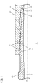
- a threaded connection 1 for steel pipe includes a tubular pin 10 and a tubular box 20.
- the pin 10 is formed by one tip portion of the steel pipe 2.
- the box 20 is made up on the pin 10 as the pin 10 is inserted thereinto.
- the portions of the steel pipe 2 other than the tip portion may be specifically referred to as "steel-pipe body".
- the pin 10 includes a pin shoulder 12, a male thread 11 and a pin seal 13.
- the pin shoulder 12 is provided on the tip portion of the pin 10 and has a toroidal surface.
- the male thread 11 is provided on the outer peripheral surface of the pin 10 and is helical in shape.
- the male thread 11 is constituted by a wedge thread.
- the pin seal 13 is located between the pin shoulder 12 and male thread 11 and is provided on the outer peripheral surface of the pin 10.
- the box 20 includes a box shoulder 22, a female thread 21 and a box seal 23.
- the box shoulder 22 corresponds to the pin shoulder 12 and is located on the innermost face of the box 20, and has a toroidal surface.
- the female thread 21 corresponds to the male thread 11 and provided on the inner peripheral surface of the box 20, and is helical in shape.
- the male thread 21 is constituted by a wedge thread.
- the box seal 23 corresponds to the pin seal 13 and is provided on the inner peripheral surface of the box 20.
- the pin shoulder 12 is spaced apart
- shoulder angle is 90° relative to the pipe axis TA.
- Shoulder angle means the angle of the pin shoulder 12 or box shoulder 22 relative to a plane perpendicular to the pipe axis (axis of the steel pipe 2) TA.
- the loading flanks 111 of the male thread 11 and the loading flanks 211 of the female thread 21 have a flank angle ⁇ .
- the stabbing flanks 112 of the male thread 11 and the stabbing flanks 212 of the female thread 21 have a flank angle ⁇ .
- the flank angle ⁇ is the angle of the loading flanks 111 and 211 relative to a plane VP perpendicular to the pipe axis (axis of the steel pipe 2) TA.
- the flank angle ⁇ is the angle of the stabbing flanks 112 and 212 relative to a plane VP perpendicular to the pipe axis TA.
- the flank angle is zero degrees. If the loading flanks 111 of the male thread 11 are inclined toward the tip of the pin 10 relative to a plane VP (in other words, if the loading flanks 211 of the female thread 21 are inclined toward the tip of the box 20 relative to a plane VP), the flank angle ⁇ of the loading flanks 111 and 211 is positive.
- the flank angle ⁇ of the loading flanks 111 and 211 is negative.
- the stabbing flanks 112 of the male thread 11 are inclined toward the steel-pipe body with the pin 10 relative to a plane VP (in other words, if the stabbing flanks 212 of the female thread 21 are inclined toward the steel-pipe body with the box 20 relative to the plane VP), the flank angle of the stabbing flanks 112 and 212 are positive.
- the flank angle of the stabbing flanks 112 and 212 is negative.
- the flank angles ⁇ and ⁇ of a wedge thread are negative.
- the entire male and female threads 11 and 21 are perfect threads without an imperfect thread area. If the entire threads 11 and 21 are constituted by perfect threads, this means a larger area of contact between the male and female threads 11 and 21, improving torque performance.
- the length of the perfect thread area i.e. areas of the male and female threads 11 and 21 constituted by perfect threads
- the threaded connection 1 for steel pipe satisfies the following expression, (1). 3 % ⁇ LP ⁇ SP / LP ⁇ 7 %
- the threaded connection 1 for steel pipe satisfies the following expression, (2). 4 % ⁇ LP ⁇ SP / LP ⁇ 6 %
- LP is the pitch between loading flanks 111 of the male thread 11 (hereinafter referred to as “loading-flank pitch”).
- SP is the pitch between stabbing flanks 112 of the male thread 11 (hereinafter referred to as “stabbing-flank pitch”).
- (LP-SP)/LP represents wedge ratio.
- the loading-flank pitch LP is equal to the pitch between loading flanks 211 of the female thread 21.
- the stabbing-flank pitch SP is equal to the pitch between stabbing flanks 212 of the female thread 21.
- the upper limit of the wedge ratio is 7 %, and preferably 6 %.
- the lower limit of the wedge ratio is 3 %, and preferably 4 %.
- the threaded connection 1 for steel pipe satisfies the following expression, (3).
- ⁇ is the flank angle of the loading flank 111 of the male thread 11.
- ⁇ is the flank angle of the stabbing flank 112 of the male thread 11.
- the flank angle ⁇ of the loading flank 111 of the male thread 11 may be equal to, or different from, the flank angle ⁇ of the stabbing flank 112 of the male thread 11.
- the flank angle ⁇ of the stabbing flank 111 of the male thread 11 is substantially equal to the flank angle ⁇ of the loading flank 211 of the female thread 21.
- the flank angle ⁇ of the stabbing flank 112 of the male thread 11 is substantially equal to the flank angle ⁇ of the stabbing flank 212 of the female thread 21.
- the values of the loading-flank pitch LP, stabbing-flank pitch SP and flank angles ⁇ and ⁇ are those before make-up.
- the pin 10 includes a pin shoulder 12, a pin seal 13 and a male thread 11.
- the pin shoulder 12 is provided on the tip portion of the pin 10.
- the pin shoulder 12 is located on the tip surface of the tubular pin 10.
- the pin shoulder 12 is a toroidal surface.
- the pin seal 13 is provided on the outer periphery of the pin 10.
- the pin seal 13 is located between the pin shoulder 12 and male thread 11.
- the pin seal 13 is constituted by, for example, the periphery of a solid of revolution obtained by rotating an arc or an elliptical arc about the pipe axis TA, or the periphery of a truncated cone having an axis represented by the pipe axis TA.
- the pin seal 13 may be constituted by a combination of two or more such peripheral surfaces.
- the box 20 includes a box shoulder 22, a box seal 23 and a female thread 21.
- the box shoulder 22 corresponds to the pin shoulder 12 and is located on the innermost face of the box 20. Similar to the pin shoulder 12, the box shoulder 22 is a toroidal surface. When the connection is made up, the box shoulder 22, together with the pin shoulder 12, forms a certain clearance.
- the box seal 23 corresponds to the pin seal 13 and is located on the inner periphery of the box 20. The box seal 23 is located between the box shoulder 22 and female thread 21.
- the box seal 23 is constituted by, for example, the periphery of a solid of revolution obtained by rotating an arc or an elliptical arc about the pipe axis TA, or the periphery of a truncated cone having an axis represented by the pipe axis TA.
- the box seal 23 may be constituted by a combination of two or more such peripheral surfaces.
- Providing a certain clearance between the pin shoulder 12 and box shoulder 22 formed when the connection is made up reduces their effects on the lock of the wedge threads. It is suitable to provide a clearance of about 1.5 mm to 2.5 mm.
- a predetermined distance from the starting position of thread-cutting on the pin 10 or the finishing position of thread-cutting on the box 20 is necessary to prevent the blade from interfering with the seal 13 or 23 during thread machining. It is suitable to provide a distance of at least 1.5 ⁇ LP (1.5 times the loading-flank pitch of the thread).
- the male and female threads 11 and 12 are constituted by wedge threads and their wedge ratio is in the range of 3 to 7 %, thereby providing high torque performance, high tension performance and high sealability.
- the threaded connection 1 may be coupling type or integral type.
- a coupling-type threaded connection includes two pins and a coupling. One of the pins is formed by a tip portion of one steel pipe. The other pin is formed by a tip portion of another steel pipe.
- the coupling includes two boxes. One of the boxes is formed by one end portion of the coupling. The other box is formed by the other end portion of the coupling. The one box is made up on the one pin as the one pin is inserted therein. The other box is located at the coupling end opposite to that with the one box, and is made up on the other pin as the other pin is inserted therein.
- an integral threaded connection is for connecting two steel pipes together, and includes a pin and a box. In the case of an integral threaded connection, one steel pipe includes a pin while the other steel pipe includes a box.
- torque performance and tension performance were evaluated using the finite element method (FEM).
- FEM finite element method
- the threaded connection being evaluated was composed by the male thread 11, pin shoulder 12, pin seal 13, female thread 21, box shoulder 22 and box seal 23, as shown in FIG. 1 .
- the male and female threads 11 and 21 were entirely constituted by wedge threads and mostly constituted by perfect threads.
- Table 1 shows the dimensions etc. of the 27 threaded connections (i.e. samples) tested in the analysis.
- the threaded connection 1 shown in FIG. 1 was used as a base, to which changes in the dimensions of the male and female threads 11 and 21 were made, and torque performance and tension performance were evaluated.
- Yield torque was defined as the maximum torque value (MTV) at which make-up torque began to yield in the make-up torque chart, which was used to evaluate torque performance.
- a load substantially equal to the tensile load under which the threaded connection 1 yields was applied to a threaded connection that had been made up, and the maximum value of the equivalent plastic strain generated at the bases of the loading flanks 111 and 211 and stabbing flanks 112 and 212 of the thread located closest to the tip in each of the male and female threads 11 and 21 was used to evaluate tension performance. From experience in real-pipe tests, the present inventors know that the risk of a break of a thread crest becomes high if equivalent plastic strain is as high as about 0.08. In view of this, they assumed that the threshold of equivalent plastic strain was 0.080 and determined a sample to have good tension performance for an equivalent plastic strain lower than 0.080. Alternatively, to provide a greater margin on the safety side, the threshold of equivalent plastic strain may be 0.070.
- a combined load simulating a physical test was applied, as shown in FIG. 4 , and the contact surface pressure generated in the seal 13, 23 was calculated.
- the average contact surface pressure and peak contact surface pressure were calculated from the distribution of seal contact surface pressure, and the value along the load route with the lowest contact surface pressure was treated as the minimum contact surface pressure for evaluation.
- the load-condition route was in line with the load-condition route specified by ISO 13679, and the axial force applied was 95 % of the yield ellipse of the connection and the pressure applied was 47.5 % of the yield ellipse of the connection.
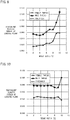
- FIGS. 5 to 7 illustrate values of yield torque obtained by the finite element analysis.
- the horizontal axis indicates wedge ratio and the vertical axis indicates MTV, where the MTV values corresponding to the wedge ratio values are plotted.
- MTV increased as wedge ratio increased, and increased particularly rapidly in the range of 2 to 3 %.
- MTV was at its maximum when wedge ratio was about 9 %, and then decreased.
- Torque performance increased presumably for the following reasons: if wedge ratio is high, the thread-crest width as measured near the tip of the pin 10 is small and, as a portion of the pin 10 with a small thread-crest width is tightened by a portion of the box 20 with a large thread-crest width, a high contact pressure is generated.
- FIGS. 8 to 10 are graphs each illustrating the relationship between the maximum value of equivalent plastic strain generated when a tensile load was applied to a threaded connection 1 that had been made up as discussed above, and wedge ratio. This equivalent plastic strain was generated at the bases of the loading flanks 111 and 211 and stabbing flanks 112 and 212 of the thread located closest to the tip in each of the male and female threads 11 and 21.
- FIGS. 11 to 13 are graphs indicating the relationships between wedge ratio and the minimum values of peak contact pressure and average contact pressure in the seal generated when combined loads were applied to the threaded connection 1.
- the figures demonstrate that changing wedge ratio does not significantly change the minimum contact surface pressure of the seal, which means that the influence of wedge ratio is small.
- wedge ratio is suitably not higher than 7 %.
- a decrease in thread-crest width is equivalent to an increase in thread-root width and leads to increased pass number during thread machining and reduced life of the insert, an extremely high wedge ratio is not desirable from manufacturing viewpoints. In view of this, the appropriate wedge ratio was found to be 3 to 7%.
Landscapes
- Engineering & Computer Science (AREA)
- General Engineering & Computer Science (AREA)
- Mechanical Engineering (AREA)
- Mining & Mineral Resources (AREA)
- Life Sciences & Earth Sciences (AREA)
- Geology (AREA)
- Fluid Mechanics (AREA)
- Environmental & Geological Engineering (AREA)
- Physics & Mathematics (AREA)
- General Life Sciences & Earth Sciences (AREA)
- Geochemistry & Mineralogy (AREA)
- Non-Disconnectible Joints And Screw-Threaded Joints (AREA)
- Earth Drilling (AREA)
Abstract
Description
- The present disclosure relates to a threaded connection for steel pipe.
- Steel pipes called oil-well pipes are used, for example, for prospecting or producing oil or natural gas in oil wells or natural-gas wells (hereinafter collectively referred to as "oil wells" or the like), developing non-conventional resources such as oil sand or shale gas, retrieving or storing carbon dioxide (Carbon dioxide Capture and Storage (CCS)), geothermal power generation, or in hot springs. A threaded connection is used to connect steel pipes.
- Such threaded connections for steel pipes are generally categorized as coupling type and integral type. A coupling-type connection connects a pair of pipes, one of which is a steel pipe and the other one is a coupling. In this case, a male thread is provided on the outer periphery of each of the ends of the steel pipe, while a female thread is provided on the inner periphery of each of the ends of the coupling. Then, a male thread of the steel pipe is screwed into a female thread of the coupling such that they are made up and connected. An integral-type connection connects a pair of pipes that are both steel pipes, and does not use a separate coupling. In this case, a male thread is provided on the outer periphery of one end of each steel pipe, while a female thread is provided on the inner periphery of the other end. Then, the male thread of one steel pipe is screwed into the female thread of the other steel pipe such that they are made up and connected.
- A connection portion of a pipe end on which a male thread is provided includes an element to be inserted into a female thread, and thus is usually referred to as "pin". A connection portion of a pipe end on which a female thread is provided includes an element for receiving a male thread, and thus is referred to as "box". A pin and a box constitute ends of pipes and are thus tubular in shape.
- When threaded connections are used at shallow levels in very deep oil wells, for example, large tensile loads derived from oil-well pipes' own weights are applied to threaded connections, while large compression loads due to thermal expansion are applied to threaded connections at deep levels.
- Further, a threaded connection is required to have sealability against pressure fluid from the inside (hereinafter also referred to as "internal pressure") and pressure fluid from the outside (hereinafter also referred to as "external pressure"); the larger the depth at which a connection is located, the higher the sealability required from the connection. In view of this, a threaded connection is provided with a metal seal, in which metal elements contact each other. The metal seal is composed of a pin seal provided on the outer periphery of the pin and a box seal provided on the inner periphery of the box. The diameter of the pin seal is slightly larger than the diameter of the box seal. The difference between the diameters of the pin seal and box seal will be referred to as amount of interference. When the threaded connection is made up and the seals are fitted onto each other, the amount of interference causes the diameter of the pin seal to decrease and the diameter of the box seal to increase. Each of the seals tries to recover their original diameters and thus produces elastic recovery forces, which produce contact pressures on the seals such that the seals tightly contact each other along the entire circumference, thereby providing sealability.
-
U.S. Reissue Patent No. 30647 (Patent Document 1),U.S. Patent No. 6158785 (Patent Document 2) andWO 2015/194193 (Patent Document 3) each disclose a threaded connection using wedge threads. A wedge thread has a thread width that gradually changes as it goes along its helical direction. A wedge thread is also known as dovetailed thread, and provides high torque performance. However, none ofPatent Documents 1 to 3 specifies at what rate the thread width of their wedge threads changes. -
JP 2012-512347 A - The following prior art documents are incorporated herein by reference.
- [Patent Document 1]
U.S. Reissue Patent No. 30647 - [Patent Document 2]
U.S. Patent No. 6158785 - [Patent Document 3]
WO 2015/194193 - [Patent Document 4]
JP 2012-512347 A - Since the loading flank and stabbing flank of a wedge thread have negative flank angles, wedge threads exhibit high torque performance as they interlock during make-up. Further, to facilitate make-up, a wedge thread may have a thread-crest width that decreases as it goes toward the tip of the pin or box. In other words, there is a difference between the loading-flank pitch and stabbing-flank pitch. This difference in pitch may be referred to as "delta lead". The delta lead determines the thread-crest widths as measured near the tips of the pin and box.
- Instead of delta lead, "wedge ratio" may be used to take the effect of the absolute value of the thread pitch into consideration. The wedge ratio is determined by dividing the delta lead by the loading-flank pitch and is the ratio of the delta lead to the loading-flank pitch, expressed as a percentage.
- If the wedge ratio is high, this means that the rate at which the thread-crest width decreases is also high. If the wedge ratio is high, the thread-crest width decreases near the tip of the pin or box. If the thread-crest width is small, the wedge thread may not be able to resist a large tensile load, and the thread crest itself may be broken. Care is thus needed in deciding the wedge ratio. The ability of a wedge thread to resist a tensile load will be hereinafter referred to as "tension performance".
- Patent Document 4 (
JP 2012-512347 A - An object of the present disclosure is to provide a threaded connection for steel pipe that provides high torque performance, high tension performance and high sealability.
- The present inventors did extensive research to find an appropriate wedge ratio that improves both torque performance and tension performance. They found out that high torque performance, high tension performance and high sealability will be achieved by changing the wedge ratio.
- A threaded connection for steel pipe according to the present disclosure includes a tubular pin and a tubular box. The tubular pin is formed by one tip portion of a steel pipe. The tubular box is made up on the pin as the pin is inserted into the box. The pin includes a pin shoulder, a male thread and a pin seal. The pin shoulder is provided on the tip portion of the pin, the pin shoulder having a toroidal surface. The male thread is provided on an outer peripheral surface of the pin. The male thread is a wedge thread. The pin seal is provided between the pin shoulder and the male thread, the pin seal being provided on the outer peripheral surface of the pin. The box includes a box shoulder, a female thread and a box seal. The box shoulder corresponds to the pin shoulder and is provided on an innermost face of the box, the box shoulder having a toroidal surface. The female thread corresponds to the male thread and is provided on an inner peripheral surface of the box. The female thread is a wedge thread. The box seal corresponds to the pin seal and is provided on the inner peripheral surface of the box. The pin shoulder is spaced apart from the box shoulder when the pin and the box have been made up. The threaded connection satisfies the following expression, (1).

- In expression (1), LP is the pitch between loading flanks of the male thread. SP is the pitch between stabbing flanks of the male thread.
-
- [
FIG. 1] FIG. 1 is a longitudinal cross-sectional view of a threaded connection for steel pipe according to an embodiment, taken along the pipe-axis direction. - [
FIG. 2] FIG. 2 is an enlarged longitudinal cross-sectional view of the male and female threads ofFIG. 1 . - [
FIG. 3] FIG. 3 is an enlarged longitudinal cross-sectional view of the metal seal inFIG. 1 . - [
FIG. 4] FIG. 4 illustrates the routes of load conditions for tests for evaluating sealing performance. - [
FIG. 5] FIG. 5 is a graph illustrating the relationship between wedge ratio and yield torque for a loading-flank pitch of 7.2 mm. - [
FIG. 6] FIG. 6 is a graph illustrating the relationship between wedge ratio and yield torque for a loading-flank pitch of 8.64 mm. - [
FIG. 7] FIG. 7 is a graph illustrating the relationship between wedge ratio and yield torque for a loading-flank pitch of 10.8 mm. - [
FIG. 8] FIG. 8 is a graph illustrating the relationship between wedge ratio and equivalent plastic strain for a loading-flank pitch of 7.2 mm. - [
FIG. 9] FIG. 9 is a graph illustrating the relationship between wedge ratio and equivalent plastic strain for a loading-flank pitch of 8.64 mm. - [
FIG. 10] FIG. 10 is a graph illustrating the relationship between wedge ratio and equivalent plastic strain for a loading-flank pitch of 10.8 mm. - [
FIG. 11] FIG. 11 is a graph illustrating the relationship between wedge ratio and minimum seal contact surface pressure for a loading-flank pitch of 7.2 mm. - [
FIG. 12] FIG. 12 is a graph illustrating the relationship between wedge ratio and minimum seal contact surface pressure for a loading-flank pitch of 8.64 mm. - [
FIG. 13] FIG. 13 is a graph illustrating the relationship between wedge ratio and minimum seal contact surface pressure for a loading-flank pitch of 10.8 mm. - A threaded connection for steel pipe according to the present embodiment includes a tubular pin and a tubular box. The tubular pin is formed by one tip portion of a steel pipe. The tubular box is made up on the pin as the pin is inserted into the box. The pin includes a pin shoulder, a male thread and a pin seal. The pin shoulder is provided on the tip portion of the pin, the pin shoulder having a toroidal surface. The male thread is provided on an outer peripheral surface of the pin. The male thread is a wedge thread. The pin seal is provided between the pin shoulder and the male thread, the pin seal being provided on the outer peripheral surface of the pin. The box includes a box shoulder, a female thread and a box seal. The box shoulder corresponds to the pin shoulder and is provided on an innermost face of the box, the box shoulder having a toroidal surface. The female thread corresponds to the male thread and is provided on an inner peripheral surface of the box. The female thread is a wedge thread. The box seal corresponds to the pin seal and is provided on the inner peripheral surface of the box. The pin shoulder is spaced apart from the box shoulder when the pin and the box have been made up. The threaded connection satisfies the following expression, (1).

- In expression (1), LP is the pitch between loading flanks of the male thread. SP is the pitch between stabbing flanks of the male thread.
- Preferably, the threaded connection satisfies the following expression, (2).

- The threaded connection may satisfy the following expression, (3).
- -10 degrees ≤ α ≤ -1 degree and -10 degrees ≤ β ≤ -1 degree (3).
- In expression (3), α is the flank angle of the loading flank of the male thread, and β is the flank angle of the stabbing flank of the male thread.
- The male thread and the female thread may each include a perfect-thread portion including a perfect thread. The perfect-thread portion may have a length of 40 to 60 mm as measured in an axial direction of the steel pipe.
- The threaded connection for steel pipe according to the present embodiment will now be described with reference to the drawings. The same and corresponding components are labeled with the same characters in the drawings, and the same description will not be repeated.
- Referring to
FIG. 1 , a threadedconnection 1 for steel pipe according to the present embodiment includes atubular pin 10 and atubular box 20. Thepin 10 is formed by one tip portion of thesteel pipe 2. Thebox 20 is made up on thepin 10 as thepin 10 is inserted thereinto. The portions of thesteel pipe 2 other than the tip portion may be specifically referred to as "steel-pipe body". - The
pin 10 includes apin shoulder 12, amale thread 11 and apin seal 13. Thepin shoulder 12 is provided on the tip portion of thepin 10 and has a toroidal surface. Themale thread 11 is provided on the outer peripheral surface of thepin 10 and is helical in shape. Themale thread 11 is constituted by a wedge thread. Thepin seal 13 is located between thepin shoulder 12 andmale thread 11 and is provided on the outer peripheral surface of thepin 10. Thebox 20 includes abox shoulder 22, afemale thread 21 and abox seal 23. Thebox shoulder 22 corresponds to thepin shoulder 12 and is located on the innermost face of thebox 20, and has a toroidal surface. Thefemale thread 21 corresponds to themale thread 11 and provided on the inner peripheral surface of thebox 20, and is helical in shape. Themale thread 21 is constituted by a wedge thread. Thebox seal 23 corresponds to thepin seal 13 and is provided on the inner peripheral surface of thebox 20. Thepin shoulder 12 is spaced apart from thebox shoulder 22 when thepin 10 andbox 20 have been made up. - Further, when the
pin 10 andbox 20 have been made up, stabbing flanks and loading flanks of themale thread 11 are in contact with stabbing flanks and loading flanks, respectively, of thefemale thread 21, and thepin seal 13 is in contact with thebox seal 23. The shoulder angle is 90° relative to the pipe axis TA. Shoulder angle means the angle of thepin shoulder 12 orbox shoulder 22 relative to a plane perpendicular to the pipe axis (axis of the steel pipe 2) TA. - Referring to
FIG. 2 , the loading flanks 111 of themale thread 11 and the loading flanks 211 of thefemale thread 21 have a flank angle α. The stabbing flanks 112 of themale thread 11 and the stabbing flanks 212 of thefemale thread 21 have a flank angle β. The flank angle α is the angle of the loading flanks 111 and 211 relative to a plane VP perpendicular to the pipe axis (axis of the steel pipe 2) TA. The flank angle β is the angle of the stabbing flanks 112 and 212 relative to a plane VP perpendicular to the pipe axis TA. If the loading flanks 111 and 211 or stabbingflanks male thread 11 are inclined toward the tip of thepin 10 relative to a plane VP (in other words, if the loading flanks 211 of thefemale thread 21 are inclined toward the tip of thebox 20 relative to a plane VP), the flank angle α of the loading flanks 111 and 211 is positive. On the contrary, if the loading flanks 111 of themale thread 11 are inclined toward the steel-pipe body with thepin 10 relative to a plane VP (in other words, if the loading flanks 211 of thefemale thread 21 are inclined toward the steel-pipe body with thebox 20 relative to a plane VP), the flank angle α of the loading flanks 111 and 211 is negative. Further, if the stabbing flanks 112 of themale thread 11 are inclined toward the steel-pipe body with thepin 10 relative to a plane VP (in other words, if the stabbing flanks 212 of thefemale thread 21 are inclined toward the steel-pipe body with thebox 20 relative to the plane VP), the flank angle of the stabbing flanks 112 and 212 are positive. On the contrary, if the stabbing flanks 112 of themale thread 11 are inclined toward the tip of thepin 10 relative to a plane VP (in other words, if the stabbing flanks 212 of thefemale thread 21 are inclined toward the tip of thebox 20 relative to a plane VP), the flank angle of the stabbing flanks 112 and 212 is negative. The flank angles α and β of a wedge thread are negative. - Although not limiting, it is preferable that the entire male and
female threads entire threads female threads female threads - The threaded
connection 1 for steel pipe satisfies the following expression, (1).
- Preferably, the threaded
connection 1 for steel pipe satisfies the following expression, (2).
- In expressions (1) and (2), LP is the pitch between loading flanks 111 of the male thread 11 (hereinafter referred to as "loading-flank pitch"). SP is the pitch between stabbing
flanks 112 of the male thread 11 (hereinafter referred to as "stabbing-flank pitch"). (LP-SP)/LP represents wedge ratio. The loading-flank pitch LP is equal to the pitch between loading flanks 211 of thefemale thread 21. The stabbing-flank pitch SP is equal to the pitch between stabbingflanks 212 of thefemale thread 21. - That is, the upper limit of the wedge ratio is 7 %, and preferably 6 %. The lower limit of the wedge ratio is 3 %, and preferably 4 %.
- The threaded
connection 1 for steel pipe satisfies the following expression, (3). - -10 degrees ≤ α ≤ -1 degree and -10 degrees ≤ β ≤ -1 degree (3).
- In expression (3), α is the flank angle of the
loading flank 111 of themale thread 11. β is the flank angle of thestabbing flank 112 of themale thread 11. The flank angle α of theloading flank 111 of themale thread 11 may be equal to, or different from, the flank angle β of thestabbing flank 112 of themale thread 11. The flank angle α of thestabbing flank 111 of themale thread 11 is substantially equal to the flank angle α of theloading flank 211 of thefemale thread 21. The flank angle β of thestabbing flank 112 of themale thread 11 is substantially equal to the flank angle β of thestabbing flank 212 of thefemale thread 21. - Exactly stating, the values of the loading-flank pitch LP, stabbing-flank pitch SP and flank angles α and β are those before make-up.
- Referring to
FIG. 1 , thepin 10 includes apin shoulder 12, apin seal 13 and amale thread 11. Thepin shoulder 12 is provided on the tip portion of thepin 10. Thepin shoulder 12 is located on the tip surface of thetubular pin 10. Thus, thepin shoulder 12 is a toroidal surface. Thepin seal 13 is provided on the outer periphery of thepin 10. Thepin seal 13 is located between thepin shoulder 12 andmale thread 11. Thepin seal 13 is constituted by, for example, the periphery of a solid of revolution obtained by rotating an arc or an elliptical arc about the pipe axis TA, or the periphery of a truncated cone having an axis represented by the pipe axis TA. Alternatively, thepin seal 13 may be constituted by a combination of two or more such peripheral surfaces. Thebox 20 includes abox shoulder 22, abox seal 23 and afemale thread 21. Thebox shoulder 22 corresponds to thepin shoulder 12 and is located on the innermost face of thebox 20. Similar to thepin shoulder 12, thebox shoulder 22 is a toroidal surface. When the connection is made up, thebox shoulder 22, together with thepin shoulder 12, forms a certain clearance. Thebox seal 23 corresponds to thepin seal 13 and is located on the inner periphery of thebox 20. Thebox seal 23 is located between thebox shoulder 22 andfemale thread 21. Thebox seal 23 is constituted by, for example, the periphery of a solid of revolution obtained by rotating an arc or an elliptical arc about the pipe axis TA, or the periphery of a truncated cone having an axis represented by the pipe axis TA. Alternatively, thebox seal 23 may be constituted by a combination of two or more such peripheral surfaces. When the connection is made up, thebox seal 23 is in contact with thepin seal 13 such that the box seal, together with the andpin seal 13, forms a metal seal. - Providing a certain clearance between the
pin shoulder 12 andbox shoulder 22 formed when the connection is made up reduces their effects on the lock of the wedge threads. It is suitable to provide a clearance of about 1.5 mm to 2.5 mm. - Regarding the positions of the pin and box seals 13 and 23, a predetermined distance from the starting position of thread-cutting on the
pin 10 or the finishing position of thread-cutting on thebox 20 is necessary to prevent the blade from interfering with theseal - According to the present embodiment, the male and
female threads - The threaded
connection 1 may be coupling type or integral type. A coupling-type threaded connection includes two pins and a coupling. One of the pins is formed by a tip portion of one steel pipe. The other pin is formed by a tip portion of another steel pipe. The coupling includes two boxes. One of the boxes is formed by one end portion of the coupling. The other box is formed by the other end portion of the coupling. The one box is made up on the one pin as the one pin is inserted therein. The other box is located at the coupling end opposite to that with the one box, and is made up on the other pin as the other pin is inserted therein. On the other hand, an integral threaded connection is for connecting two steel pipes together, and includes a pin and a box. In the case of an integral threaded connection, one steel pipe includes a pin while the other steel pipe includes a box. - Although an embodiment has been described, the present invention is not limited to the above-illustrated embodiment, and various modifications are possible without departing from the spirit of the invention.
- To verify the effects of the present embodiment, torque performance and tension performance were evaluated using the finite element method (FEM). A wedge-threaded connection was evaluated, and steel pipes described below were used.
- Size: 9-5/8 inches (with an outer diameter of the pipe body of 244.48 mm and an inner diameter of the pipe body of 216.8 mm)
- Material: OCTG material L80 in accordance with the API standards (with a nominal proof stress of YS=552 MPa (80 ksi))
- Thread taper: 1/12
- Thread length: 50 mm (pin) and 60 mm (box)
- Thread height: 1.8 mm
- Flank angle: -5 degrees (for both loading flank and stabbing flank)
- Loading-flank pitch: 7.2 mm, 8.64 mm or 10.8 mm
- Wedge ratio: 2 to 10 %
- Stabbing-flank pitch: calculated backward based on wedge ratio
- The threaded connection being evaluated was composed by the
male thread 11,pin shoulder 12,pin seal 13,female thread 21,box shoulder 22 andbox seal 23, as shown inFIG. 1 . The male andfemale threads - Table 1 shows the dimensions etc. of the 27 threaded connections (i.e. samples) tested in the analysis.
-
TABLE1 No. Size Material Thread taper ing Thread length [mm] Thread height [mm] Flank angle [deg] Loading-flank pitch [mm] Stabbing-flank pitch [mm] Delta lead [mm] Wedge ratio [%] MTV [ft.lbs] Equivalent plastic strain Minimum contact surface pressure at sealing surface Threshold male thread female thread Average contact surface pressure Peak contact surface pressure loading flank stabbing flank loading flank stabbing flank [MPa] [MPa] 1 7.200 7.056 0.144 2.00 62731 0.0248 0.006196 0.0434 0.0052 331 513 0.08 2 6.984 0.216 3.00 67916 0.0267 0.008118 0.0435 0.0200 346 511 0.08 3 6.912 0.288 4.00 70746 0.0297 0.012269 0.0468 0.0244 340 506 0.08 4 6.84 0.36 5.00 73333 0.0342 0.014879 0.0559 0.0322 322 508 0.08 5 6.768 0.432 6.00 74365 0.0407 0.021087 0.0722 0.0430 320 503 0.08 6 6.696 0.504 7.00 74186 0.0468 0.024766 0.0733 0.0538 336 507 0.08 7 6.624 0.576 8.00 73613 0.0564 0.036258 0.0963 0.0622 329 507 0.08 8 6.552 0.648 9.00 73722 0.0570 0.040827 0.1512 0.0669 321 502 0.08 9 6.48 0.72 10.00 72673 0.1236 0.066684 0.2405 0.1127 320 500 0.08 10 8.640 8.467 0.173 2.00 54502 0.0141 0.000632 0.0552 0.0139 329 513 0.08 11 8.381 0.259 3.00 57358 0.0152 0.002521 0.0523 0.0162 341 511 0.08 12 8.294 0.346 4.00 59063 0.0177 0.004959 0.0509 0.0211 328 510 0.08 13 8.208 0.432 5.00 59906 0.0181 0.008264 0.0538 0.0254 326 512 0.08 14 9-5/8" L80 1/12 50 1.8 -5 8.122 0.518 6.00 61626 0.0244 0.011875 0.0621 0.0303 325 509 0.08 15 8.035 0.605 7.00 64152 0.0246 0.014734 0.0700 0.0355 328 509 0.08 16 7.919 0.691 8.00 64334 0.0322 0.016315 0.0098 0.0537 328 512 0.08 17 7.862 0.778 9.00 64632 0.0567 0.024744 0.0926 0.0553 328 510 0.08 18 7.776 0.864 10.00 64298 0.0582 0.031936 0.1270 0.0773 327 508 0.08 19 10.800 10.584 0.216 2.00 34522 0.0439 0.001014 0.04 0.0159 332 517 0.08 20 10.476 0.324 3.00 48662 0.0469 0.001427 0.0774 0.0158 331 517 0.08 21 10.368 0.432 4.00 50529 0.0457 0.001936 0.0772 0.0159 334 514 0.08 22 10.26 0.54 5.00 51538 0.0446 0.002697 0.0TΓ3 0.0162 333 512 0.08 23 10.152 0.648 6.00 52104 0.0444 0.003816 0.0776 0.0164 331 515 0.08 24 10.044 0.756 7.00 52392 0.0437 0.004612 0.0778 0.0168 330 515 0.08 25 9.936 0.864 8.00 54285 0.0435 0.006698 0.0734 0.0320 327 505 0.08 26_ 9.828 0.972 9.00 54909 0.0459 0.009535 0.0727 0.0461 330 508 0.08 27 9.72 1.08 10.00 55757 0.0374 0.013948 0.1004 0.0611 335 507 0.08 - For the analysis, the threaded
connection 1 shown inFIG. 1 was used as a base, to which changes in the dimensions of the male andfemale threads - Yield torque was defined as the maximum torque value (MTV) at which make-up torque began to yield in the make-up torque chart, which was used to evaluate torque performance.
- A load substantially equal to the tensile load under which the threaded
connection 1 yields was applied to a threaded connection that had been made up, and the maximum value of the equivalent plastic strain generated at the bases of the loading flanks 111 and 211 and stabbingflanks female threads - To evaluate sealing performance, a combined load simulating a physical test was applied, as shown in
FIG. 4 , and the contact surface pressure generated in theseal -
FIGS. 5 to 7 illustrate values of yield torque obtained by the finite element analysis. In each of these graphs, the horizontal axis indicates wedge ratio and the vertical axis indicates MTV, where the MTV values corresponding to the wedge ratio values are plotted. Regardless of thread pitch, MTV increased as wedge ratio increased, and increased particularly rapidly in the range of 2 to 3 %. As can be determined inFIG. 6 , MTV was at its maximum when wedge ratio was about 9 %, and then decreased. - Torque performance increased presumably for the following reasons: if wedge ratio is high, the thread-crest width as measured near the tip of the
pin 10 is small and, as a portion of thepin 10 with a small thread-crest width is tightened by a portion of thebox 20 with a large thread-crest width, a high contact pressure is generated. -
FIGS. 8 to 10 are graphs each illustrating the relationship between the maximum value of equivalent plastic strain generated when a tensile load was applied to a threadedconnection 1 that had been made up as discussed above, and wedge ratio. This equivalent plastic strain was generated at the bases of the loading flanks 111 and 211 and stabbingflanks female threads - As shown in
FIG. 8 , it was found that if the loading-flank pitch LP=7.2 mm, the maximum value of the equivalent plastic strain generated in the male thread exceeded 0.070 when wedge ratio was 6 % or higher, and the maximum value of equivalent plastic strain exceeded 0.080 when wedge ratio reached 8 %. - As shown in
FIG. 9 , it was found that, if the loading-flank pitch LP=8.64 mm, the equivalent plastic strain generated in the male thread exceeded 0.070 when wedge ratio was 7 %, and the maximum equivalent plastic strain exceeded 0.080 when wedge ratio reached 9 %. - As shown in
FIG. 10 , it was found that, if the loading-flank pitch LP=10.8 mm, the maximum equivalent plastic strain generated in the male thread exceeded 0.080 when wedge ratio was 10 % or above such that the threads were likely to be broken. - As discussed above,
FIGS. 11 to 13 are graphs indicating the relationships between wedge ratio and the minimum values of peak contact pressure and average contact pressure in the seal generated when combined loads were applied to the threadedconnection 1. The figures demonstrate that changing wedge ratio does not significantly change the minimum contact surface pressure of the seal, which means that the influence of wedge ratio is small. - These results demonstrate that, to improve torque performance, the higher wedge ratio, the better. However, as discussed above, if wedge ratio is too high, the risk of a break of the thread near the tip of the pin (male thread) and/or box (female thread) increases; in view of this, wedge ratio is suitably not higher than 7 %. Further, since a decrease in thread-crest width is equivalent to an increase in thread-root width and leads to increased pass number during thread machining and reduced life of the insert, an extremely high wedge ratio is not desirable from manufacturing viewpoints. In view of this, the appropriate wedge ratio was found to be 3 to 7%.
-
- 1: threaded connection for steel pipe
- 10: pin
- 11: male thread
- 12: pin shoulder
- 13: pin seal
- 20: box
- 21: female thread
- 22: box shoulder
- 23: box seal
- 111, 211: loading flank
- 112, 212: stabbing flank
- LP: loading-flank pitch
- SP: stabbing-flank pitch
Claims (4)
- A threaded connection for steel pipe, comprising:a tubular pin formed by one tip portion of a steel pipe; anda tubular box adapted to be made up on the pin as the pin is inserted into the box,the pin including:a pin shoulder provided on the tip portion of the pin, the pin shoulder having a toroidal surface;a male thread provided on an outer peripheral surface of the pin, the male thread being a wedge thread; anda pin seal provided between the pin shoulder and the male thread, the pin seal being provided on the outer peripheral surface of the pin,the box including:a box shoulder corresponding to the pin shoulder and provided on an innermost face of the box, the box shoulder having a toroidal surface;a female thread corresponding to the male thread and provided on an inner peripheral surface of the box, the female thread being a wedge thread; anda box seal corresponding to the pin seal and provided on the inner peripheral surface of the box,wherein the pin shoulder is spaced apart from the box shoulder when the pin and the box have been made up, andthe threaded connection satisfies the following expression, (1):

- The threaded connection for the steel pipe according to claim 1, wherein the threaded connection satisfies the following expression, (2):

- The threaded connection for the steel pipe according to claim 1 or 2, wherein the threaded connection satisfies the following expression, (3):
-10 degrees ≤ α ≤ -1 degree and -10 degrees ≤ β ≤ -1 degree (3),
where, in expression (3), α is the flank angle of the loading flank of the male thread, and β is the flank angle of the stabbing flank of the male thread. - The threaded connection for the steel pipe according to any one of claims 1 to 3, wherein the male thread and the female thread each include a perfect-thread portion including a perfect thread, and
the perfect-thread portion has a length of 40 to 60 mm as measured in an axial direction of the steel pipe.
Applications Claiming Priority (2)
| Application Number | Priority Date | Filing Date | Title |
|---|---|---|---|
| JP2018192230 | 2018-10-11 | ||
| PCT/JP2019/028959 WO2020075366A1 (en) | 2018-10-11 | 2019-07-24 | Threaded coupling for steel pipe |
Publications (3)
| Publication Number | Publication Date |
|---|---|
| EP3865753A1 true EP3865753A1 (en) | 2021-08-18 |
| EP3865753A4 EP3865753A4 (en) | 2021-11-10 |
| EP3865753B1 EP3865753B1 (en) | 2022-12-07 |
Family
ID=70164867
Family Applications (1)
| Application Number | Title | Priority Date | Filing Date |
|---|---|---|---|
| EP19870342.3A Active EP3865753B1 (en) | 2018-10-11 | 2019-07-24 | Threaded coupling for steel pipe |
Country Status (11)
| Country | Link |
|---|---|
| US (1) | US11506311B2 (en) |
| EP (1) | EP3865753B1 (en) |
| JP (1) | JP7237084B2 (en) |
| CN (1) | CN112823256B (en) |
| AR (1) | AR116680A1 (en) |
| BR (1) | BR112021004076B1 (en) |
| CA (1) | CA3115198C (en) |
| MX (1) | MX2021003985A (en) |
| RU (1) | RU2764606C1 (en) |
| SA (1) | SA521421480B1 (en) |
| WO (1) | WO2020075366A1 (en) |
Families Citing this family (5)
| Publication number | Priority date | Publication date | Assignee | Title |
|---|---|---|---|---|
| EP3865753B1 (en) * | 2018-10-11 | 2022-12-07 | Nippon Steel Corporation | Threaded coupling for steel pipe |
| BR112021000168B1 (en) * | 2018-10-11 | 2023-12-19 | Nippon Steel Corporation | THREADED CONNECTION FOR STEEL PIPE |
| CN115362328B (en) * | 2020-06-26 | 2025-09-05 | 日本制铁株式会社 | Threaded joints for steel pipes |
| CA3238483A1 (en) * | 2022-01-31 | 2023-08-03 | Tomas Jansson | Drilling component |
| WO2025104964A1 (en) * | 2023-11-14 | 2025-05-22 | 日本製鉄株式会社 | Threaded joint for steel pipe |
Family Cites Families (25)
| Publication number | Priority date | Publication date | Assignee | Title |
|---|---|---|---|---|
| US30647A (en) | 1860-11-13 | Improvement in forming cartridge-cases | ||
| US3989284A (en) * | 1975-04-23 | 1976-11-02 | Hydril Company | Tubular connection |
| USRE30647E (en) | 1975-04-23 | 1981-06-16 | Hydril Company | Tubular connection |
| US4822081A (en) * | 1987-03-23 | 1989-04-18 | Xl Systems | Driveable threaded tubular connection |
| US6158785A (en) * | 1998-08-06 | 2000-12-12 | Hydril Company | Multi-start wedge thread for tubular connection |
| US6976711B2 (en) * | 2002-04-19 | 2005-12-20 | Hydril Company Lp | Threaded connection especially for radially plastically expandable conduit |
| US7243957B2 (en) | 2004-12-30 | 2007-07-17 | Hydril Company Lp | Pseudo two-step connection |
| US8668233B2 (en) * | 2004-12-30 | 2014-03-11 | Hydril Company | Threaded connection with perturbed flanks |
| FR2939861B1 (en) | 2008-12-16 | 2010-12-24 | Vallourec Mannesmann Oil & Gas France | TUBULAR JOINT WITH AUTOBLOATING THREAD USED IN THE PETROLEUM INDUSTRY |
| FR2944553B1 (en) * | 2009-04-17 | 2011-06-03 | Vallourec Mannesmann Oil & Gas | TUBULAR COMPONENT FOR DRILLING AND OPERATING HYDROCARBON WELLS AND RESULTING THREAD |
| US20120074693A1 (en) | 2010-09-24 | 2012-03-29 | Hydril Company | Step-to-step wedge thread connections and related methods |
| US20160186899A1 (en) | 2011-08-05 | 2016-06-30 | Vallourec Oil And Gas France | Tubular connection with self-locking thread form used in the oil industry |
| FR2979968B1 (en) * | 2011-09-13 | 2014-06-27 | Vallourec Mannesmann Oil & Gas | ASSEMBLY FOR THE PRODUCTION OF A THREADED JOINT FOR DRILLING AND OPERATING HYDROCARBON WELLS AND RESULTING THREAD |
| US8931809B2 (en) | 2012-09-21 | 2015-01-13 | Vallourec Oil And Gas France | Tubular threaded connection |
| FR3008763B1 (en) * | 2013-07-18 | 2015-07-31 | Vallourec Mannesmann Oil & Gas | ASSEMBLY FOR THE PRODUCTION OF A THREADED JOINT FOR DRILLING AND OPERATING HYDROCARBON WELLS AND RESULTING THREAD |
| CA2921411C (en) * | 2013-09-06 | 2018-07-10 | Nippon Steel & Sumitomo Metal Corporation | Threaded connection for steel pipe |
| US10253573B2 (en) * | 2013-12-05 | 2019-04-09 | Nippon Steel & Sumitomo Metal Corporation | Threaded joint for steel pipes |
| MX376939B (en) * | 2014-06-20 | 2025-03-07 | Nippon Steel Corp | THREADED JOINT FOR STEEL PIPES. |
| UA122422C2 (en) * | 2015-10-21 | 2020-11-10 | Ніппон Стіл & Сумітомо Метал Корпорейшн | Threaded fitting for steel pipes |
| UA119127C2 (en) * | 2015-12-15 | 2019-04-25 | Ніппон Стіл Енд Сумітомо Метал Корпорейшн | RIVER CONNECTION FOR STEEL PIPE |
| RU2702315C1 (en) * | 2016-06-08 | 2019-10-07 | Валлурек Ойл Энд Гэс Франс | Threaded connection for steel pipe |
| EP3514432B1 (en) | 2016-09-16 | 2022-04-06 | Nippon Steel Corporation | Threaded joint |
| MX2019007514A (en) * | 2017-01-18 | 2019-09-04 | Nippon Steel Corp | Threaded joint for steel pipes. |
| EP3473798B2 (en) | 2017-10-20 | 2025-06-18 | Vallourec Oil And Gas France | Threaded connection partially in a self-locking engagement |
| EP3865753B1 (en) * | 2018-10-11 | 2022-12-07 | Nippon Steel Corporation | Threaded coupling for steel pipe |
-
2019
- 2019-07-24 EP EP19870342.3A patent/EP3865753B1/en active Active
- 2019-07-24 BR BR112021004076-5A patent/BR112021004076B1/en active IP Right Grant
- 2019-07-24 CN CN201980066922.3A patent/CN112823256B/en active Active
- 2019-07-24 WO PCT/JP2019/028959 patent/WO2020075366A1/en not_active Ceased
- 2019-07-24 CA CA3115198A patent/CA3115198C/en active Active
- 2019-07-24 RU RU2021106478A patent/RU2764606C1/en active
- 2019-07-24 MX MX2021003985A patent/MX2021003985A/en unknown
- 2019-07-24 JP JP2020549976A patent/JP7237084B2/en active Active
- 2019-07-24 US US17/280,958 patent/US11506311B2/en active Active
- 2019-10-02 AR ARP190102804A patent/AR116680A1/en active IP Right Grant
-
2021
- 2021-03-15 SA SA521421480A patent/SA521421480B1/en unknown
Also Published As
| Publication number | Publication date |
|---|---|
| US20210341085A1 (en) | 2021-11-04 |
| EP3865753A4 (en) | 2021-11-10 |
| EP3865753B1 (en) | 2022-12-07 |
| CN112823256B (en) | 2022-10-25 |
| CN112823256A (en) | 2021-05-18 |
| JP7237084B2 (en) | 2023-03-10 |
| RU2764606C1 (en) | 2022-01-18 |
| US11506311B2 (en) | 2022-11-22 |
| CA3115198A1 (en) | 2020-04-16 |
| MX2021003985A (en) | 2021-05-27 |
| CA3115198C (en) | 2023-06-13 |
| BR112021004076B1 (en) | 2023-11-07 |
| AR116680A1 (en) | 2021-06-02 |
| JPWO2020075366A1 (en) | 2021-09-02 |
| WO2020075366A1 (en) | 2020-04-16 |
| SA521421480B1 (en) | 2022-11-16 |
| BR112021004076A2 (en) | 2021-05-25 |
Similar Documents
| Publication | Publication Date | Title |
|---|---|---|
| EP3865753B1 (en) | Threaded coupling for steel pipe | |
| EP4027044B1 (en) | Threaded connection for steel pipe | |
| CN202469289U (en) | Pipe screw coupling | |
| EP3366968A1 (en) | Threaded fitting for steel pipes | |
| US12018777B2 (en) | Threaded connection for steel pipe | |
| EP3862607B1 (en) | Threaded connection for steel pipe | |
| EP3865752B1 (en) | Threaded connection for steel pipe | |
| EP3246611B1 (en) | Screw joint for pipe | |
| CA3169103C (en) | Threaded connection for steel pipe | |
| US20200200304A1 (en) | Threaded Connection for Steel Pipes | |
| BR112021022614B1 (en) | THREADED CONNECTION FOR STEEL PIPE | |
| OA21386A (en) | Threaded joint for steel pipe. | |
| BR112022015434B1 (en) | THREADED CONNECTION FOR STEEL PIPE |
Legal Events
| Date | Code | Title | Description |
|---|---|---|---|
| STAA | Information on the status of an ep patent application or granted ep patent |
Free format text: STATUS: THE INTERNATIONAL PUBLICATION HAS BEEN MADE |
|
| PUAI | Public reference made under article 153(3) epc to a published international application that has entered the european phase |
Free format text: ORIGINAL CODE: 0009012 |
|
| STAA | Information on the status of an ep patent application or granted ep patent |
Free format text: STATUS: REQUEST FOR EXAMINATION WAS MADE |
|
| 17P | Request for examination filed |
Effective date: 20210223 |
|
| AK | Designated contracting states |
Kind code of ref document: A1 Designated state(s): AL AT BE BG CH CY CZ DE DK EE ES FI FR GB GR HR HU IE IS IT LI LT LU LV MC MK MT NL NO PL PT RO RS SE SI SK SM TR |
|
| A4 | Supplementary search report drawn up and despatched |
Effective date: 20211007 |
|
| RIC1 | Information provided on ipc code assigned before grant |
Ipc: F16L 15/04 20060101ALI20211002BHEP Ipc: F16L 15/00 20060101ALI20211002BHEP Ipc: F16L 5/06 20060101ALI20211002BHEP Ipc: E21B 17/042 20060101AFI20211002BHEP |
|
| DAV | Request for validation of the european patent (deleted) | ||
| DAX | Request for extension of the european patent (deleted) | ||
| REG | Reference to a national code |
Ref country code: DE Ref legal event code: R079 Ref document number: 602019023010 Country of ref document: DE Free format text: PREVIOUS MAIN CLASS: F16L0015040000 Ipc: E21B0017042000 |
|
| GRAP | Despatch of communication of intention to grant a patent |
Free format text: ORIGINAL CODE: EPIDOSNIGR1 |
|
| STAA | Information on the status of an ep patent application or granted ep patent |
Free format text: STATUS: GRANT OF PATENT IS INTENDED |
|
| RIC1 | Information provided on ipc code assigned before grant |
Ipc: F16L 15/04 20060101ALI20220728BHEP Ipc: F16L 15/00 20060101ALI20220728BHEP Ipc: F16L 5/06 20060101ALI20220728BHEP Ipc: E21B 17/042 20060101AFI20220728BHEP |
|
| INTG | Intention to grant announced |
Effective date: 20220811 |
|
| GRAS | Grant fee paid |
Free format text: ORIGINAL CODE: EPIDOSNIGR3 |
|
| GRAA | (expected) grant |
Free format text: ORIGINAL CODE: 0009210 |
|
| STAA | Information on the status of an ep patent application or granted ep patent |
Free format text: STATUS: THE PATENT HAS BEEN GRANTED |
|
| AK | Designated contracting states |
Kind code of ref document: B1 Designated state(s): AL AT BE BG CH CY CZ DE DK EE ES FI FR GB GR HR HU IE IS IT LI LT LU LV MC MK MT NL NO PL PT RO RS SE SI SK SM TR |
|
| REG | Reference to a national code |
Ref country code: GB Ref legal event code: FG4D |
|
| REG | Reference to a national code |
Ref country code: RO Ref legal event code: EPE |
|
| REG | Reference to a national code |
Ref country code: CH Ref legal event code: EP Ref country code: AT Ref legal event code: REF Ref document number: 1536410 Country of ref document: AT Kind code of ref document: T Effective date: 20221215 |
|
| REG | Reference to a national code |
Ref country code: DE Ref legal event code: R096 Ref document number: 602019023010 Country of ref document: DE |
|
| REG | Reference to a national code |
Ref country code: IE Ref legal event code: FG4D |
|
| REG | Reference to a national code |
Ref country code: NO Ref legal event code: T2 Effective date: 20221207 |
|
| REG | Reference to a national code |
Ref country code: LT Ref legal event code: MG9D |
|
| REG | Reference to a national code |
Ref country code: NL Ref legal event code: MP Effective date: 20221207 |
|
| PG25 | Lapsed in a contracting state [announced via postgrant information from national office to epo] |
Ref country code: SE Free format text: LAPSE BECAUSE OF FAILURE TO SUBMIT A TRANSLATION OF THE DESCRIPTION OR TO PAY THE FEE WITHIN THE PRESCRIBED TIME-LIMIT Effective date: 20221207 Ref country code: LT Free format text: LAPSE BECAUSE OF FAILURE TO SUBMIT A TRANSLATION OF THE DESCRIPTION OR TO PAY THE FEE WITHIN THE PRESCRIBED TIME-LIMIT Effective date: 20221207 Ref country code: FI Free format text: LAPSE BECAUSE OF FAILURE TO SUBMIT A TRANSLATION OF THE DESCRIPTION OR TO PAY THE FEE WITHIN THE PRESCRIBED TIME-LIMIT Effective date: 20221207 Ref country code: ES Free format text: LAPSE BECAUSE OF FAILURE TO SUBMIT A TRANSLATION OF THE DESCRIPTION OR TO PAY THE FEE WITHIN THE PRESCRIBED TIME-LIMIT Effective date: 20221207 |
|
| PG25 | Lapsed in a contracting state [announced via postgrant information from national office to epo] |
Ref country code: RS Free format text: LAPSE BECAUSE OF FAILURE TO SUBMIT A TRANSLATION OF THE DESCRIPTION OR TO PAY THE FEE WITHIN THE PRESCRIBED TIME-LIMIT Effective date: 20221207 Ref country code: PL Free format text: LAPSE BECAUSE OF FAILURE TO SUBMIT A TRANSLATION OF THE DESCRIPTION OR TO PAY THE FEE WITHIN THE PRESCRIBED TIME-LIMIT Effective date: 20221207 Ref country code: LV Free format text: LAPSE BECAUSE OF FAILURE TO SUBMIT A TRANSLATION OF THE DESCRIPTION OR TO PAY THE FEE WITHIN THE PRESCRIBED TIME-LIMIT Effective date: 20221207 Ref country code: HR Free format text: LAPSE BECAUSE OF FAILURE TO SUBMIT A TRANSLATION OF THE DESCRIPTION OR TO PAY THE FEE WITHIN THE PRESCRIBED TIME-LIMIT Effective date: 20221207 Ref country code: GR Free format text: LAPSE BECAUSE OF FAILURE TO SUBMIT A TRANSLATION OF THE DESCRIPTION OR TO PAY THE FEE WITHIN THE PRESCRIBED TIME-LIMIT Effective date: 20230308 |
|
| PG25 | Lapsed in a contracting state [announced via postgrant information from national office to epo] |
Ref country code: NL Free format text: LAPSE BECAUSE OF FAILURE TO SUBMIT A TRANSLATION OF THE DESCRIPTION OR TO PAY THE FEE WITHIN THE PRESCRIBED TIME-LIMIT Effective date: 20221207 |
|
| PG25 | Lapsed in a contracting state [announced via postgrant information from national office to epo] |
Ref country code: SM Free format text: LAPSE BECAUSE OF FAILURE TO SUBMIT A TRANSLATION OF THE DESCRIPTION OR TO PAY THE FEE WITHIN THE PRESCRIBED TIME-LIMIT Effective date: 20221207 Ref country code: PT Free format text: LAPSE BECAUSE OF FAILURE TO SUBMIT A TRANSLATION OF THE DESCRIPTION OR TO PAY THE FEE WITHIN THE PRESCRIBED TIME-LIMIT Effective date: 20230410 Ref country code: EE Free format text: LAPSE BECAUSE OF FAILURE TO SUBMIT A TRANSLATION OF THE DESCRIPTION OR TO PAY THE FEE WITHIN THE PRESCRIBED TIME-LIMIT Effective date: 20221207 Ref country code: CZ Free format text: LAPSE BECAUSE OF FAILURE TO SUBMIT A TRANSLATION OF THE DESCRIPTION OR TO PAY THE FEE WITHIN THE PRESCRIBED TIME-LIMIT Effective date: 20221207 |
|
| PG25 | Lapsed in a contracting state [announced via postgrant information from national office to epo] |
Ref country code: SK Free format text: LAPSE BECAUSE OF FAILURE TO SUBMIT A TRANSLATION OF THE DESCRIPTION OR TO PAY THE FEE WITHIN THE PRESCRIBED TIME-LIMIT Effective date: 20221207 Ref country code: IS Free format text: LAPSE BECAUSE OF FAILURE TO SUBMIT A TRANSLATION OF THE DESCRIPTION OR TO PAY THE FEE WITHIN THE PRESCRIBED TIME-LIMIT Effective date: 20230407 Ref country code: AL Free format text: LAPSE BECAUSE OF FAILURE TO SUBMIT A TRANSLATION OF THE DESCRIPTION OR TO PAY THE FEE WITHIN THE PRESCRIBED TIME-LIMIT Effective date: 20221207 |
|
| REG | Reference to a national code |
Ref country code: DE Ref legal event code: R026 Ref document number: 602019023010 Country of ref document: DE |
|
| PLBI | Opposition filed |
Free format text: ORIGINAL CODE: 0009260 |
|
| PLAX | Notice of opposition and request to file observation + time limit sent |
Free format text: ORIGINAL CODE: EPIDOSNOBS2 |
|
| 26 | Opposition filed |
Opponent name: TENARIS CONNECTIONS BV Effective date: 20230907 |
|
| PG25 | Lapsed in a contracting state [announced via postgrant information from national office to epo] |
Ref country code: DK Free format text: LAPSE BECAUSE OF FAILURE TO SUBMIT A TRANSLATION OF THE DESCRIPTION OR TO PAY THE FEE WITHIN THE PRESCRIBED TIME-LIMIT Effective date: 20221207 |
|
| PG25 | Lapsed in a contracting state [announced via postgrant information from national office to epo] |
Ref country code: SI Free format text: LAPSE BECAUSE OF FAILURE TO SUBMIT A TRANSLATION OF THE DESCRIPTION OR TO PAY THE FEE WITHIN THE PRESCRIBED TIME-LIMIT Effective date: 20221207 |
|
| PLBB | Reply of patent proprietor to notice(s) of opposition received |
Free format text: ORIGINAL CODE: EPIDOSNOBS3 |
|
| REG | Reference to a national code |
Ref country code: AT Ref legal event code: UEP Ref document number: 1536410 Country of ref document: AT Kind code of ref document: T Effective date: 20221207 |
|
| PG25 | Lapsed in a contracting state [announced via postgrant information from national office to epo] |
Ref country code: MC Free format text: LAPSE BECAUSE OF FAILURE TO SUBMIT A TRANSLATION OF THE DESCRIPTION OR TO PAY THE FEE WITHIN THE PRESCRIBED TIME-LIMIT Effective date: 20221207 |
|
| PG25 | Lapsed in a contracting state [announced via postgrant information from national office to epo] |
Ref country code: MC Free format text: LAPSE BECAUSE OF FAILURE TO SUBMIT A TRANSLATION OF THE DESCRIPTION OR TO PAY THE FEE WITHIN THE PRESCRIBED TIME-LIMIT Effective date: 20221207 |
|
| REG | Reference to a national code |
Ref country code: CH Ref legal event code: PL |
|
| REG | Reference to a national code |
Ref country code: BE Ref legal event code: MM Effective date: 20230731 |
|
| PG25 | Lapsed in a contracting state [announced via postgrant information from national office to epo] |
Ref country code: LU Free format text: LAPSE BECAUSE OF NON-PAYMENT OF DUE FEES Effective date: 20230724 |
|
| PG25 | Lapsed in a contracting state [announced via postgrant information from national office to epo] |
Ref country code: LU Free format text: LAPSE BECAUSE OF NON-PAYMENT OF DUE FEES Effective date: 20230724 |
|
| REG | Reference to a national code |
Ref country code: IE Ref legal event code: MM4A |
|
| PG25 | Lapsed in a contracting state [announced via postgrant information from national office to epo] |
Ref country code: CH Free format text: LAPSE BECAUSE OF NON-PAYMENT OF DUE FEES Effective date: 20230731 |
|
| PG25 | Lapsed in a contracting state [announced via postgrant information from national office to epo] |
Ref country code: BE Free format text: LAPSE BECAUSE OF NON-PAYMENT OF DUE FEES Effective date: 20230731 |
|
| PG25 | Lapsed in a contracting state [announced via postgrant information from national office to epo] |
Ref country code: IE Free format text: LAPSE BECAUSE OF NON-PAYMENT OF DUE FEES Effective date: 20230724 |
|
| PG25 | Lapsed in a contracting state [announced via postgrant information from national office to epo] |
Ref country code: IE Free format text: LAPSE BECAUSE OF NON-PAYMENT OF DUE FEES Effective date: 20230724 |
|
| PG25 | Lapsed in a contracting state [announced via postgrant information from national office to epo] |
Ref country code: BG Free format text: LAPSE BECAUSE OF FAILURE TO SUBMIT A TRANSLATION OF THE DESCRIPTION OR TO PAY THE FEE WITHIN THE PRESCRIBED TIME-LIMIT Effective date: 20221207 |
|
| PG25 | Lapsed in a contracting state [announced via postgrant information from national office to epo] |
Ref country code: BG Free format text: LAPSE BECAUSE OF FAILURE TO SUBMIT A TRANSLATION OF THE DESCRIPTION OR TO PAY THE FEE WITHIN THE PRESCRIBED TIME-LIMIT Effective date: 20221207 |
|
| PLCK | Communication despatched that opposition was rejected |
Free format text: ORIGINAL CODE: EPIDOSNREJ1 |
|
| APAH | Appeal reference modified |
Free format text: ORIGINAL CODE: EPIDOSCREFNO |
|
| APBP | Date of receipt of notice of appeal recorded |
Free format text: ORIGINAL CODE: EPIDOSNNOA2O |
|
| REG | Reference to a national code |
Ref country code: DE Ref legal event code: R100 Ref document number: 602019023010 Country of ref document: DE |
|
| APBU | Appeal procedure closed |
Free format text: ORIGINAL CODE: EPIDOSNNOA9O |
|
| PGFP | Annual fee paid to national office [announced via postgrant information from national office to epo] |
Ref country code: GB Payment date: 20250605 Year of fee payment: 7 |
|
| PLBN | Opposition rejected |
Free format text: ORIGINAL CODE: 0009273 |
|
| STAA | Information on the status of an ep patent application or granted ep patent |
Free format text: STATUS: OPPOSITION REJECTED |
|
| PGFP | Annual fee paid to national office [announced via postgrant information from national office to epo] |
Ref country code: FR Payment date: 20250610 Year of fee payment: 7 |
|
| PGFP | Annual fee paid to national office [announced via postgrant information from national office to epo] |
Ref country code: RO Payment date: 20250619 Year of fee payment: 7 |
|
| PG25 | Lapsed in a contracting state [announced via postgrant information from national office to epo] |
Ref country code: CY Free format text: LAPSE BECAUSE OF FAILURE TO SUBMIT A TRANSLATION OF THE DESCRIPTION OR TO PAY THE FEE WITHIN THE PRESCRIBED TIME-LIMIT; INVALID AB INITIO Effective date: 20190724 |
|
| 27O | Opposition rejected |
Effective date: 20250708 |
|
| PG25 | Lapsed in a contracting state [announced via postgrant information from national office to epo] |
Ref country code: HU Free format text: LAPSE BECAUSE OF FAILURE TO SUBMIT A TRANSLATION OF THE DESCRIPTION OR TO PAY THE FEE WITHIN THE PRESCRIBED TIME-LIMIT; INVALID AB INITIO Effective date: 20190724 |
|
| PGFP | Annual fee paid to national office [announced via postgrant information from national office to epo] |
Ref country code: DE Payment date: 20250528 Year of fee payment: 7 |
|
| PGFP | Annual fee paid to national office [announced via postgrant information from national office to epo] |
Ref country code: NO Payment date: 20250709 Year of fee payment: 7 |
|
| PGFP | Annual fee paid to national office [announced via postgrant information from national office to epo] |
Ref country code: IT Payment date: 20250623 Year of fee payment: 7 |
|
| PGFP | Annual fee paid to national office [announced via postgrant information from national office to epo] |
Ref country code: AT Payment date: 20250625 Year of fee payment: 7 |
|
| PG25 | Lapsed in a contracting state [announced via postgrant information from national office to epo] |
Ref country code: TR Free format text: LAPSE BECAUSE OF FAILURE TO SUBMIT A TRANSLATION OF THE DESCRIPTION OR TO PAY THE FEE WITHIN THE PRESCRIBED TIME-LIMIT Effective date: 20221207 |