EP3865706A1 - Vertical shaft wind power generation device and hydropower generation device accommodated in container - Google Patents
Vertical shaft wind power generation device and hydropower generation device accommodated in container Download PDFInfo
- Publication number
- EP3865706A1 EP3865706A1 EP19870489.2A EP19870489A EP3865706A1 EP 3865706 A1 EP3865706 A1 EP 3865706A1 EP 19870489 A EP19870489 A EP 19870489A EP 3865706 A1 EP3865706 A1 EP 3865706A1
- Authority
- EP
- European Patent Office
- Prior art keywords
- container
- generation device
- vertical axis
- power generation
- wind turbine
- Prior art date
- Legal status (The legal status is an assumption and is not a legal conclusion. Google has not performed a legal analysis and makes no representation as to the accuracy of the status listed.)
- Granted
Links
Images



















Classifications
-
- F—MECHANICAL ENGINEERING; LIGHTING; HEATING; WEAPONS; BLASTING
- F03—MACHINES OR ENGINES FOR LIQUIDS; WIND, SPRING, OR WEIGHT MOTORS; PRODUCING MECHANICAL POWER OR A REACTIVE PROPULSIVE THRUST, NOT OTHERWISE PROVIDED FOR
- F03D—WIND MOTORS
- F03D13/00—Assembly, mounting or commissioning of wind motors; Arrangements specially adapted for transporting wind motor components
- F03D13/40—Arrangements or methods specially adapted for transporting wind motor components
-
- F—MECHANICAL ENGINEERING; LIGHTING; HEATING; WEAPONS; BLASTING
- F03—MACHINES OR ENGINES FOR LIQUIDS; WIND, SPRING, OR WEIGHT MOTORS; PRODUCING MECHANICAL POWER OR A REACTIVE PROPULSIVE THRUST, NOT OTHERWISE PROVIDED FOR
- F03D—WIND MOTORS
- F03D13/00—Assembly, mounting or commissioning of wind motors; Arrangements specially adapted for transporting wind motor components
- F03D13/10—Assembly of wind motors; Arrangements for erecting wind motors
-
- B—PERFORMING OPERATIONS; TRANSPORTING
- B65—CONVEYING; PACKING; STORING; HANDLING THIN OR FILAMENTARY MATERIAL
- B65D—CONTAINERS FOR STORAGE OR TRANSPORT OF ARTICLES OR MATERIALS, e.g. BAGS, BARRELS, BOTTLES, BOXES, CANS, CARTONS, CRATES, DRUMS, JARS, TANKS, HOPPERS, FORWARDING CONTAINERS; ACCESSORIES, CLOSURES, OR FITTINGS THEREFOR; PACKAGING ELEMENTS; PACKAGES
- B65D88/00—Large containers
- B65D88/02—Large containers rigid
- B65D88/12—Large containers rigid specially adapted for transport
-
- B—PERFORMING OPERATIONS; TRANSPORTING
- B65—CONVEYING; PACKING; STORING; HANDLING THIN OR FILAMENTARY MATERIAL
- B65D—CONTAINERS FOR STORAGE OR TRANSPORT OF ARTICLES OR MATERIALS, e.g. BAGS, BARRELS, BOTTLES, BOXES, CANS, CARTONS, CRATES, DRUMS, JARS, TANKS, HOPPERS, FORWARDING CONTAINERS; ACCESSORIES, CLOSURES, OR FITTINGS THEREFOR; PACKAGING ELEMENTS; PACKAGES
- B65D90/00—Component parts, details or accessories for large containers
- B65D90/008—Doors for containers, e.g. ISO-containers
-
- F—MECHANICAL ENGINEERING; LIGHTING; HEATING; WEAPONS; BLASTING
- F03—MACHINES OR ENGINES FOR LIQUIDS; WIND, SPRING, OR WEIGHT MOTORS; PRODUCING MECHANICAL POWER OR A REACTIVE PROPULSIVE THRUST, NOT OTHERWISE PROVIDED FOR
- F03B—MACHINES OR ENGINES FOR LIQUIDS
- F03B11/00—Parts or details not provided for in, or of interest apart from, the preceding groups, e.g. wear-protection couplings, between turbine and generator
-
- F—MECHANICAL ENGINEERING; LIGHTING; HEATING; WEAPONS; BLASTING
- F03—MACHINES OR ENGINES FOR LIQUIDS; WIND, SPRING, OR WEIGHT MOTORS; PRODUCING MECHANICAL POWER OR A REACTIVE PROPULSIVE THRUST, NOT OTHERWISE PROVIDED FOR
- F03B—MACHINES OR ENGINES FOR LIQUIDS
- F03B17/00—Other machines or engines
- F03B17/06—Other machines or engines using liquid flow with predominantly kinetic energy conversion, e.g. of swinging-flap type, "run-of-river", "ultra-low head"
- F03B17/061—Other machines or engines using liquid flow with predominantly kinetic energy conversion, e.g. of swinging-flap type, "run-of-river", "ultra-low head" with rotation axis substantially in flow direction
-
- F—MECHANICAL ENGINEERING; LIGHTING; HEATING; WEAPONS; BLASTING
- F03—MACHINES OR ENGINES FOR LIQUIDS; WIND, SPRING, OR WEIGHT MOTORS; PRODUCING MECHANICAL POWER OR A REACTIVE PROPULSIVE THRUST, NOT OTHERWISE PROVIDED FOR
- F03B—MACHINES OR ENGINES FOR LIQUIDS
- F03B3/00—Machines or engines of reaction type; Parts or details peculiar thereto
- F03B3/04—Machines or engines of reaction type; Parts or details peculiar thereto with substantially axial flow throughout rotors, e.g. propeller turbines
-
- F—MECHANICAL ENGINEERING; LIGHTING; HEATING; WEAPONS; BLASTING
- F03—MACHINES OR ENGINES FOR LIQUIDS; WIND, SPRING, OR WEIGHT MOTORS; PRODUCING MECHANICAL POWER OR A REACTIVE PROPULSIVE THRUST, NOT OTHERWISE PROVIDED FOR
- F03D—WIND MOTORS
- F03D13/00—Assembly, mounting or commissioning of wind motors; Arrangements specially adapted for transporting wind motor components
- F03D13/20—Arrangements for mounting or supporting wind motors; Masts or towers for wind motors
-
- F—MECHANICAL ENGINEERING; LIGHTING; HEATING; WEAPONS; BLASTING
- F03—MACHINES OR ENGINES FOR LIQUIDS; WIND, SPRING, OR WEIGHT MOTORS; PRODUCING MECHANICAL POWER OR A REACTIVE PROPULSIVE THRUST, NOT OTHERWISE PROVIDED FOR
- F03D—WIND MOTORS
- F03D3/00—Wind motors with rotation axis substantially perpendicular to the air flow entering the rotor
- F03D3/005—Wind motors with rotation axis substantially perpendicular to the air flow entering the rotor the axis being vertical
-
- F—MECHANICAL ENGINEERING; LIGHTING; HEATING; WEAPONS; BLASTING
- F03—MACHINES OR ENGINES FOR LIQUIDS; WIND, SPRING, OR WEIGHT MOTORS; PRODUCING MECHANICAL POWER OR A REACTIVE PROPULSIVE THRUST, NOT OTHERWISE PROVIDED FOR
- F03D—WIND MOTORS
- F03D3/00—Wind motors with rotation axis substantially perpendicular to the air flow entering the rotor
- F03D3/06—Rotors
-
- F—MECHANICAL ENGINEERING; LIGHTING; HEATING; WEAPONS; BLASTING
- F03—MACHINES OR ENGINES FOR LIQUIDS; WIND, SPRING, OR WEIGHT MOTORS; PRODUCING MECHANICAL POWER OR A REACTIVE PROPULSIVE THRUST, NOT OTHERWISE PROVIDED FOR
- F03D—WIND MOTORS
- F03D3/00—Wind motors with rotation axis substantially perpendicular to the air flow entering the rotor
- F03D3/06—Rotors
- F03D3/062—Rotors characterised by their construction elements
- F03D3/064—Fixing wind engaging parts to rest of rotor
-
- F—MECHANICAL ENGINEERING; LIGHTING; HEATING; WEAPONS; BLASTING
- F03—MACHINES OR ENGINES FOR LIQUIDS; WIND, SPRING, OR WEIGHT MOTORS; PRODUCING MECHANICAL POWER OR A REACTIVE PROPULSIVE THRUST, NOT OTHERWISE PROVIDED FOR
- F03D—WIND MOTORS
- F03D9/00—Adaptations of wind motors for special use; Combinations of wind motors with apparatus driven thereby; Wind motors specially adapted for installation in particular locations
- F03D9/008—Adaptations of wind motors for special use; Combinations of wind motors with apparatus driven thereby; Wind motors specially adapted for installation in particular locations the wind motor being combined with water energy converters, e.g. a water turbine
-
- H—ELECTRICITY
- H02—GENERATION; CONVERSION OR DISTRIBUTION OF ELECTRIC POWER
- H02S—GENERATION OF ELECTRIC POWER BY CONVERSION OF INFRARED RADIATION, VISIBLE LIGHT OR ULTRAVIOLET LIGHT, e.g. USING PHOTOVOLTAIC [PV] MODULES
- H02S40/00—Components or accessories in combination with PV modules, not provided for in groups H02S10/00 - H02S30/00
- H02S40/30—Electrical components
- H02S40/38—Energy storage means, e.g. batteries, structurally associated with PV modules
-
- F—MECHANICAL ENGINEERING; LIGHTING; HEATING; WEAPONS; BLASTING
- F05—INDEXING SCHEMES RELATING TO ENGINES OR PUMPS IN VARIOUS SUBCLASSES OF CLASSES F01-F04
- F05B—INDEXING SCHEME RELATING TO WIND, SPRING, WEIGHT, INERTIA OR LIKE MOTORS, TO MACHINES OR ENGINES FOR LIQUIDS COVERED BY SUBCLASSES F03B, F03D AND F03G
- F05B2240/00—Components
- F05B2240/10—Stators
- F05B2240/14—Casings, housings, nacelles, gondels or the like, protecting or supporting assemblies there within
- F05B2240/142—Casings, housings, nacelles, gondels or the like, protecting or supporting assemblies there within in the form of a standard ISO container
-
- F—MECHANICAL ENGINEERING; LIGHTING; HEATING; WEAPONS; BLASTING
- F05—INDEXING SCHEMES RELATING TO ENGINES OR PUMPS IN VARIOUS SUBCLASSES OF CLASSES F01-F04
- F05B—INDEXING SCHEME RELATING TO WIND, SPRING, WEIGHT, INERTIA OR LIKE MOTORS, TO MACHINES OR ENGINES FOR LIQUIDS COVERED BY SUBCLASSES F03B, F03D AND F03G
- F05B2240/00—Components
- F05B2240/20—Rotors
- F05B2240/21—Rotors for wind turbines
- F05B2240/211—Rotors for wind turbines with vertical axis
-
- F—MECHANICAL ENGINEERING; LIGHTING; HEATING; WEAPONS; BLASTING
- F05—INDEXING SCHEMES RELATING TO ENGINES OR PUMPS IN VARIOUS SUBCLASSES OF CLASSES F01-F04
- F05B—INDEXING SCHEME RELATING TO WIND, SPRING, WEIGHT, INERTIA OR LIKE MOTORS, TO MACHINES OR ENGINES FOR LIQUIDS COVERED BY SUBCLASSES F03B, F03D AND F03G
- F05B2240/00—Components
- F05B2240/90—Mounting on supporting structures or systems
-
- F—MECHANICAL ENGINEERING; LIGHTING; HEATING; WEAPONS; BLASTING
- F05—INDEXING SCHEMES RELATING TO ENGINES OR PUMPS IN VARIOUS SUBCLASSES OF CLASSES F01-F04
- F05B—INDEXING SCHEME RELATING TO WIND, SPRING, WEIGHT, INERTIA OR LIKE MOTORS, TO MACHINES OR ENGINES FOR LIQUIDS COVERED BY SUBCLASSES F03B, F03D AND F03G
- F05B2240/00—Components
- F05B2240/90—Mounting on supporting structures or systems
- F05B2240/91—Mounting on supporting structures or systems on a stationary structure
- F05B2240/915—Mounting on supporting structures or systems on a stationary structure which is vertically adjustable
- F05B2240/9152—Mounting on supporting structures or systems on a stationary structure which is vertically adjustable by being hinged
- F05B2240/91521—Mounting on supporting structures or systems on a stationary structure which is vertically adjustable by being hinged at ground level
-
- F—MECHANICAL ENGINEERING; LIGHTING; HEATING; WEAPONS; BLASTING
- F05—INDEXING SCHEMES RELATING TO ENGINES OR PUMPS IN VARIOUS SUBCLASSES OF CLASSES F01-F04
- F05B—INDEXING SCHEME RELATING TO WIND, SPRING, WEIGHT, INERTIA OR LIKE MOTORS, TO MACHINES OR ENGINES FOR LIQUIDS COVERED BY SUBCLASSES F03B, F03D AND F03G
- F05B2260/00—Function
- F05B2260/02—Transport, e.g. specific adaptations or devices for conveyance
-
- Y—GENERAL TAGGING OF NEW TECHNOLOGICAL DEVELOPMENTS; GENERAL TAGGING OF CROSS-SECTIONAL TECHNOLOGIES SPANNING OVER SEVERAL SECTIONS OF THE IPC; TECHNICAL SUBJECTS COVERED BY FORMER USPC CROSS-REFERENCE ART COLLECTIONS [XRACs] AND DIGESTS
- Y02—TECHNOLOGIES OR APPLICATIONS FOR MITIGATION OR ADAPTATION AGAINST CLIMATE CHANGE
- Y02E—REDUCTION OF GREENHOUSE GAS [GHG] EMISSIONS, RELATED TO ENERGY GENERATION, TRANSMISSION OR DISTRIBUTION
- Y02E10/00—Energy generation through renewable energy sources
- Y02E10/20—Hydro energy
-
- Y—GENERAL TAGGING OF NEW TECHNOLOGICAL DEVELOPMENTS; GENERAL TAGGING OF CROSS-SECTIONAL TECHNOLOGIES SPANNING OVER SEVERAL SECTIONS OF THE IPC; TECHNICAL SUBJECTS COVERED BY FORMER USPC CROSS-REFERENCE ART COLLECTIONS [XRACs] AND DIGESTS
- Y02—TECHNOLOGIES OR APPLICATIONS FOR MITIGATION OR ADAPTATION AGAINST CLIMATE CHANGE
- Y02E—REDUCTION OF GREENHOUSE GAS [GHG] EMISSIONS, RELATED TO ENERGY GENERATION, TRANSMISSION OR DISTRIBUTION
- Y02E10/00—Energy generation through renewable energy sources
- Y02E10/50—Photovoltaic [PV] energy
-
- Y—GENERAL TAGGING OF NEW TECHNOLOGICAL DEVELOPMENTS; GENERAL TAGGING OF CROSS-SECTIONAL TECHNOLOGIES SPANNING OVER SEVERAL SECTIONS OF THE IPC; TECHNICAL SUBJECTS COVERED BY FORMER USPC CROSS-REFERENCE ART COLLECTIONS [XRACs] AND DIGESTS
- Y02—TECHNOLOGIES OR APPLICATIONS FOR MITIGATION OR ADAPTATION AGAINST CLIMATE CHANGE
- Y02E—REDUCTION OF GREENHOUSE GAS [GHG] EMISSIONS, RELATED TO ENERGY GENERATION, TRANSMISSION OR DISTRIBUTION
- Y02E10/00—Energy generation through renewable energy sources
- Y02E10/70—Wind energy
- Y02E10/728—Onshore wind turbines
-
- Y—GENERAL TAGGING OF NEW TECHNOLOGICAL DEVELOPMENTS; GENERAL TAGGING OF CROSS-SECTIONAL TECHNOLOGIES SPANNING OVER SEVERAL SECTIONS OF THE IPC; TECHNICAL SUBJECTS COVERED BY FORMER USPC CROSS-REFERENCE ART COLLECTIONS [XRACs] AND DIGESTS
- Y02—TECHNOLOGIES OR APPLICATIONS FOR MITIGATION OR ADAPTATION AGAINST CLIMATE CHANGE
- Y02E—REDUCTION OF GREENHOUSE GAS [GHG] EMISSIONS, RELATED TO ENERGY GENERATION, TRANSMISSION OR DISTRIBUTION
- Y02E10/00—Energy generation through renewable energy sources
- Y02E10/70—Wind energy
- Y02E10/74—Wind turbines with rotation axis perpendicular to the wind direction
-
- Y—GENERAL TAGGING OF NEW TECHNOLOGICAL DEVELOPMENTS; GENERAL TAGGING OF CROSS-SECTIONAL TECHNOLOGIES SPANNING OVER SEVERAL SECTIONS OF THE IPC; TECHNICAL SUBJECTS COVERED BY FORMER USPC CROSS-REFERENCE ART COLLECTIONS [XRACs] AND DIGESTS
- Y02—TECHNOLOGIES OR APPLICATIONS FOR MITIGATION OR ADAPTATION AGAINST CLIMATE CHANGE
- Y02E—REDUCTION OF GREENHOUSE GAS [GHG] EMISSIONS, RELATED TO ENERGY GENERATION, TRANSMISSION OR DISTRIBUTION
- Y02E70/00—Other energy conversion or management systems reducing GHG emissions
- Y02E70/30—Systems combining energy storage with energy generation of non-fossil origin
Definitions
- the present invention relates to a vertical axis wind power generation device capable of being easily transported and simply installed as a power supply source in non-electrified areas of developing countries and/or disaster areas affected by hazards and to a container-accommodated hydropower generation device having excellent transportability.
- Patent Documents 1 to 4 have proposed wind power generation devices in consideration of easy transport and simple installation.
- Patent Document 1 describes that solar panels serving as side surfaces of a transport box are unfolded upward so as to be raised on a frame of the box in an inclined manner and that a wind power generator is attached to a side of the frame.
- Patent Documents 2, 3 describe that a container used when transporting a wind power generator is used as a foundation for setting up the wind power generator.
- Patent Document 4 describes that blades of a wind turbine of a vertical axis wind power generation device can be folded along a main shaft.
- Important requirements of power source systems for supplying electric power in non-electrified areas of developing countries and/or disaster areas affected by hazards include easy transport, simple installation, and power generation capability.
- Patent Document 1 assumes that a unit is dimensioned as a 1-m cube, so that sufficient power generation capability cannot not be achieved. Further, although the size of the 1-m cube is advantageous in transport in that the unit can be transported even by a small truck, in the case where more than one units are loaded in and transported by a truck, they do not tightly fit within the dimensions of a back of the truck and leave a useless space, which is uneconomical. Patent Documents 2, 3 use containers each having a standard dimension, so that they can be efficiently transported by ground transport (by trucks or trains), ocean freight and/or air freight. The wind power generation devices of Patent Documents 1 to 3, however, all employ horizontal axis wind turbines, so that they have poor power generation efficiency when they have compact configurations.
- a wind turbine has a compact size in consideration of transportability to and easy installation in non-electrified areas of developing countries and/or disaster areas affected by hazards, the wind turbine has poor power generation efficiency and insufficient power generation capability.
- the horizontal axis wind turbines are hardly rotated at low wind speed, so that it may not be possible to find an installation location in which electric power can be effectively generated in the case where they are installed in limited spaces in disaster areas.
- Patent Document 4 does not have the problem of the horizontal axis wind turbines because it employs a vertical axis wind turbine, and provides excellent transportability and installation because the blades can be folded. However, the document does not disclose how the folded wind turbine is transported.
- An object of the present invention is to provide a vertical axis wind power generation device capable of being easily transported and simply installed and providing sufficient power generation capability even where it has a compact configuration.
- Another object of the present invention is to provide a container-accommodated hydropower generation device which is a compact hydropower generation device having improved transportability.
- a vertical axis wind power generation device of the present invention includes:
- the wind power generation device since the wind power generation device is of a vertical axis type, it is possible to efficiently generate electric power even where the device has such a compact size that it can be transported by a single truck and to efficiently generate electric power at low wind speed, unlike that of a horizontal axis type. Further, since the wind power generation device includes a container having a standard dimension for freight transport, and the wind turbine is accommodatable in the container together with the power generator, it can be treated as a general standard-sized container when transported by ground transport (by trucks or trains), ocean freight and/or air freight and thus is excellent in transportability. For this reason, the power generation device can have a largest possible size within a size restriction for transport, which is advantageous in ensuring power generation capability.
- the container In order to set up the wind turbine, the container is provided with a support-column fixing part for fixing the support column of the wind turbine thereto, so that the wind turbine can be easily set up on the container, and the container can be used as a foundation for the wind turbine.
- the "container having a standard dimension for freight transport” may have a dimension meeting at least a national standard for container transport or a dimension meeting, for example, a standard established by the national administrative body or international authorities such as the International Organization for Standardization (ISO).
- ISO International Organization for Standardization
- the vertical axis wind turbine may be foldable or disassemblable. Where the wind turbine is foldable or disassemblable, a larger vertical axis wind turbine can be easily transported.
- the vertical axis wind turbine may be of an assembled type which allows disassembly of the wind turbine, the vertical axis wind turbine of a foldable type can further facilitate installation operation and can be installed speedily.
- the wind turbine may be accommodatable in a folded or disassembled state in the container.
- a larger vertical axis wind turbine can be accommodated in the container.
- the container may include an inclining mount inside the container, the inclining mount being inclined so as to be lowered toward an opening side at a longitudinal end of the container and configured to carry a folded body of the wind turbine on the inclining mount such that the folded body can be moved in and out through an opening.
- the container includes the inclining mount thereinside and accommodates the folded body of the wind turbine on the inclining mount, so that the folded body of the wind turbine can slide on the inclining mount due to self-weight so as to be moved out of the container at an installation site, which facilitates installation operation at the site. For example, it is possible to manually take out a folded wind turbine from a container without using heavy equipment.
- the wind turbine In order to accommodate the wind turbine in the container, the wind turbine is pushed up on the inclining mount so as to be received in the container. Since factories or storage warehouses of vertical axis wind power generation devices are generally equipped with heavy machinery or the like, a problem is unlikely to arise in accommodating the devices. Where the vertical axis wind power generation device is set up in a disaster area, however, it is preferable that the wind turbine can be easily taken out from the container by human power at an installation site where the environment is not ready for use of heavy equipment. When the vertical axis wind power generation device is no longer needed and is removed, the traffic situation in the surrounding area is likely be recovered, and heavy equipment can thus be used easily. Alternatively, it is also possible to manually push up the wind turbine on the inclining mount by using a winch or the like from the state of Fig. 39 to accommodate it in the state of Fig. 38 .
- the container may include a withdrawing and unfolding mechanism configured to withdraw the folded body of the wind turbine by using the inclining mount while unfolding the folded body and to assist operation of setting up the wind turbine.
- the container includes such a withdrawing and unfolding mechanism, the installation operation can further be facilitated and expedited.
- the vertical axis wind turbine has an overall length shorter than that of a longer side of the container, it can be accommodated without being folded, so that the installation operation of such a wind turbine can be more speedily as compared with that of a folded type.
- the container may include a double door configured to open and close the opening at the longitudinal end of the container, and the door in an opened state may serve as outriggers. Since the door of the container serves as outriggers, it is possible to secure stability of the container and the wind turbine fixed thereto against e.g. strong wind and/or earthquake, without providing dedicated outriggers.
- the container may include an inner door disposed an inner side of the door and configured to prevent entry from an outside.
- the door is used as outriggers, if nothing is provided, the inside would be left open and may be subjected to entry of rain and wind and/or theft.
- the inner door can prevent such entry and/or theft or the like.
- a solar panel assembled with a stand so as to be installable outside or on the container and configured to photovoltaically generate electric power and a secondary battery configured to store the generated electric power, the solar panel and the secondary battery being accommodatable in the container together with the wind turbine in the folded or disassembled state.
- the solar panel is assembled with the stand, it is only necessary to place the solar panel outside or on the container to install it.
- the solar panels may be shaped such that they can be sequentially stacked in a nesting manner when they are accommodated in the container, so that a large number of solar panels can be accommodated in the container.
- the vertical axis wind power generation device may include: a main-shaft-unit folding mechanism configured to allow the main shaft unit including the support column and the main shaft to be folded; and a blade-unit folding mechanism configured to allow blade units, which are constituted by the blades and the arms, to be folded along the main shaft unit in a folded state.
- a main-shaft-unit folding mechanism configured to allow the main shaft unit including the support column and the main shaft to be folded
- a blade-unit folding mechanism configured to allow blade units, which are constituted by the blades and the arms, to be folded along the main shaft unit in a folded state.
- the support column can have a relatively large height so as to securely receive a wind force and thus provide sufficient power generation capability, without causing the problem of transportability. This makes it possible to easily transport the wind power generation device, to install it easily and speedily, and to ensure power generation capability even where it has a compact configuration. Thus, it is possible to meet a demand for electric power in non-electrified areas and/or disaster areas affected by hazards.
- the main-shaft-unit folding mechanism may include a support-column tilting mechanism tiltably coupling the support column to a wind turbine mount. Where the support column is tiltable, the device can be transported in a more compactly folded state and thus has greater transportability.
- the main-shaft-unit folding mechanism may include a main-shaft tilting coupling mechanism coupling a main-shaft lower-end supporting member located at an upper end of the support column and rotatably supporting the main shaft at a lower end of the main shaft to the upper end of the support column such that the main shaft is tiltable, the main-shaft tilting coupling mechanism being configured to cause the main shaft in a laid state to assume a posture along the support column.
- the main shaft can be folded so as to assume a posture along the support column, so that the device can be transported in a more compactly folded state and thus has greater transportability.
- the blade-unit folding mechanism may include rotary coupling members provided to the respective blades and disposed around the main shaft so as to be rotatable, the rotary coupling members being coupled to base ends of the respective arms.
- the rotary coupling members can be rotated about the main shaft such that the plurality of blades are folded in an overlapped state, which makes it possible to compactly fold the device.
- the blade-unit folding mechanism may include arm-base-end bending coupling parts coupling base ends of the arms to the main shaft in a bendable manner and arm-tip-end bending coupling parts coupling tip ends of the arms to the blades in a bendable manner.
- the blade unit can be folded such that the respective blades are arranged along the main shaft by bending the arms, which also makes it possible to compactly fold the device.
- the door may include a wind-turbine holding part configured to hold the wind turbine in the accommodated state in the container such that the wind turbine extends along an inner side of the door of the container.
- a wind-turbine holding part configured to hold the wind turbine in the accommodated state in the container such that the wind turbine extends along an inner side of the door of the container.
- the door is provided with the wind-turbine holding part configured to hold the wind turbine in the accommodated state in the container such that the wind turbine extends along the inner side of the door of the container.
- the wind turbine can be received on a dolly or the like and be moved to a desired installation position without using a slope or the like.
- the wind turbine is removed from an installation position and accommodated into the container, it is possible to open the door and to easily hold the wind turbine along the inner side of the door by the wind-turbine holding part without using a slope or the like.
- the wind-turbine holding part may have a function of changing a position of the wind turbine from the inner side of the door to a position distant from the inner side of the door.
- the wind turbine holding part makes it possible to change the position of the wind turbine from the inner side of the door to a position distant from the inner side of the door, so that the wind turbine can be directly moved and fixed to a desired installation position, without being unloaded from the door.
- the door may include a water-turbine holding part configured to hold a water turbine in an accommodated state in the container such that the water turbine extends along the inner side of the door of the container.
- a water-turbine holding part configured to hold a water turbine in an accommodated state in the container such that the water turbine extends along the inner side of the door of the container.
- the container may be provided with a linear guiding device configured to liftably guide the wind turbine between a use position at which the blades project upward from a height range of the container and an accommodation position at which the blades are accommodated within the height range of the container.
- a linear guiding device configured to liftably guide the wind turbine between a use position at which the blades project upward from a height range of the container and an accommodation position at which the blades are accommodated within the height range of the container.
- the vertical axis wind power generation device may include a lifting device of a winding type configured to wind a winding member connected to an upper portion of the container and a lower portion of the support column such that the wind turbine can be lifted and lowered.
- the lifting device can be operated to lift or lower the wind turbine, so that the operation of lifting and lowering the wind turbine is further facilitated.
- the lifting winder is a feature for winding the winding member connected to the upper portion of the container and the lower portion of the support column, it may have a simple constitution. For example, it may be a common winch or the like.
- the winding member may be a chain, a rope, a belt or the like.
- the support-column fixing part may be provided only for fixing purpose separately from the lifting device or the like, or the lifting device and/or the linear guiding device may also serve as the support-column fixing part.
- the motion is limited to directions other than the vertical direction. Thus, because the lifting device restricts a vertical motion, the wind turbine is fixed to the container.
- the lifting device may be of an electrically-powered type which is configured to be driven by an electric motor to perform winding operation.
- the lifting winder may be of a manual type, where it is of an electrically-powered type, the wind turbine can be more easily lifted and lowered through an operation of a switch.
- the container may have a ceiling surface having an upper opening configured to allow the wind turbine to move in and out therethrough, and the support column may be provided with an inner lid configured to tightly close the upper opening when the wind turbine is raised.
- the support column is provided with the inner lid, the upper opening of the container is closed by the inner lid when the wind turbine is raised to the use position, so that a dedicated operation for closing the inner lid is not necessary.
- a container-accommodated hydropower generation device of the present invention includes: a container having a standard dimension for freight transport; and a compact hydropower generation device capable of being installed in a water channel and being accommodated in and removed from the container. According to the hydropower generation device having this constitution, the compact hydropower generation device is accommodated in the container having the standard dimension, so that it has excellent transportability.
- the vertical axis wind power generation device W includes: a wind turbine 1; a container 2; and a power generator 3 configured to generate electric power by rotation of the wind turbine 1.
- the vertical axis wind power generation device W further includes a secondary battery 4 and a control panel 50.
- the wind turbine 1 is a wind turbine of a vertical axis type including: a support column 6; a main shaft 5 disposed on an upper portion of the support column so as to be rotatable about a vertical axis; a plurality of blades 7 extending in a vertical direction around the main shaft 5 and coupled to the main shaft 5 through arms 8.
- the plurality of blades 7 and the arms 8 constitute a rotary blade 9.
- the support column 6 is constituted by a round steel tube or the like, and the support column 6 is provided with a main-shaft lower-end supporting member 15 at an upper end thereof.
- the main-shaft lower-end supporting member 15 includes a short tubular casing, and the main shaft 5 is rotatably supported at its lower end by double rows of rolling bearings (not illustrated) disposed inside the casing.
- the power generator 3 is disposed in the casing of the main-shaft lower-end supporting member 15 and includes an input shaft coupled to the main shaft 5.
- the container 2 has a standard dimension for freight transport.
- the standard for freight transport may at least refer to a national standard for container transport or may refer to, for example, a standard established by the national administrative body or international authorities such as the International Organization for Standardization (ISO).
- the container 2 of this example corresponds to a 20-feet container according to the ISO standard for dry containers.
- the container 2 of Fig. 1 includes an opening 2a at a longitudinal end thereof and a double door 10 configured to open and close the opening 2a.
- the wind turbine 1 is a foldable type which can be accommodated in the container 2 as shown in Fig. 2 .
- the wind turbine 1 is constituted by a main shaft unit 11 including the support column 6 and the main shaft 5 as well as a plurality of blade units 12 including the blades 7 and the arms 8 supporting the blades 7.
- the vertical axis wind power generation device W includes a main-shaft-unit folding mechanism 13 which allows the main shaft unit 11 to be folded and a blade-unit folding mechanism 14 which allows the blade units 12 to be folded so as to extend along the folded main shaft unit 11.
- the main-shaft-unit folding mechanism 13 is mainly constituted by a support-column tilting mechanism 18 and a main-shaft tilting coupling mechanism 19.
- the support-column tilting mechanism 18 is a mechanism tiltably coupling the support column 6 to a wind turbine mount 17.
- the main-shaft tilting coupling mechanism 19 is a mechanism coupling the main-shaft lower-end supporting member 15 such that the main shaft 5 is tiltable and configured to cause the main shaft 5 in a laid state to assume a posture along the support column 6.
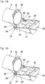
- the support column 6 in a raised posture is supported by the wind turbine mount 17 at its lower end so as to be positioned along the opening 2a of the container 2 and is fixed at an upper edge of the opening 2a of the container 2 by a support-column fixing part 20 provided to the container 2 as shown in Fig. 4 and Fig. 5 .
- the support-column fixing part 20 is constituted by: a two-pronged metal fitting having a semicircular receiving part 20a ( Fig. 5 ) matching a part of an outer periphery of the support column 6 and a base end fixed to a lower surface of a ceiling of the container 2; and a stopping member (not illustrated) for stopping the support column 6 to the receiving part 20a.
- the stopping member may be constituted by, for example, a semicircular metal fitting or a rope removably attached to the receiving part 20a so as to surround a remaining part of the outer periphery of the support column 6, along which the receiving part 20a does not extend.
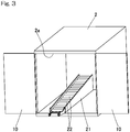
- an inclining mount 21 is disposed in the container 2.
- the inclining mount 21 is a stand inclined such that a longitudinal end of the inclining mount on a side of the opening 2a is lowered, the inclining mount being configured to carry and store a folded body of the wind turbine 1 on the inclining mount such that the folded body can be moved in and out through the opening 2a as shown in Fig. 2 .
- the folded body of the wind turbine 1 includes the main shaft unit 11 and the blade units 12 in a folded state.
- the inclining mount 21 includes a guiding part for facilitating movement of the folded body of the wind turbine 1 in a longitudinal direction.
- the guiding part is constituted by a plurality of rollers 22 arranged in the longitudinal direction of the inclining mount 21.
- the inclining mount 21 is constituted as an inclined roller conveyor including the rollers 22 and a frame. It should be noted that the inclining mount may have a flat upper surface and is provided with a resin sheet (not illustrated) for friction reduction as the guiding part.
- the inclining mount 21 has a smaller width dimension than a dimension of the container 2 in a shorter width direction of the container and is disposed at a position displaced from the center of the container 2 in the shorter width direction in accordance with the shape and dimension of the folded body of the wind turbine 1.
- the container 2 may be provided with, instead of the inclining mount 21, a stand (not illustrated) having a flat upper surface for storing the folded body and moving it in and out.
- the secondary battery 4 and the control panel 50 are disposed in a fixed manner on a floor surface of the container 2 at an inner position lateral to the inclining mount 21.
- the control panel 50 includes, for example, an AC/DC converter configured to convert alternating current (AC) power generated by the power generator 3 into a voltage which can be stored in the secondary battery 4, a power generation controller configured to control power generation by rotation of the wind turbine 1, and an inverter configured to convert the electric power stored in the secondary battery 4 into sine wave AC similar to commercial AC power or into rectangular wave AC.
- AC alternating current
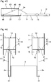
- Fig. 16 to Fig. 21 show the support-column tilting mechanism 18 of the main-shaft-unit folding mechanism 13 ( Fig. 1 ).
- the wind turbine mount 17 is coupled to a lower end of the inclining mount 21 in an inclination direction so as to be tiltable about a horizontal support shaft 23 and can be fixed in a raised posture for accommodation as shown in Fig. 16 and in a horizontal position for use as shown in Fig. 17 by a locking fixture (not illustrated), such as a pin, removably inserted into a locking hole 24.
- a locking fixture such as a pin
- the wind turbine mount 17 has a part on a base end side with respect to its center, which is provided with a support-column coupling plate 25, and opposite side portions each having a tip end provided with a fixed receiving hook 26 and a turnable overhanging hook 27.
- the support column 6 has a base end provided with a supported bar 28 fixed through brackets 29, 29 at opposite side portions thereof and a base-end coupling plate 30. With the supported bar 28 being engaged with the receiving hooks 26 of the wind turbine mount 17 as shown in Fig. 18 and engaged from above with the overhanging hooks 27 of the wind turbine mount 17 as shown in Fig. 19 , the support column 6 is raised as shown in Fig. 20 .
- the base-end coupling plate 30 of the support column 6 is superposed on the support-column coupling plate 25 of the wind turbine mount 17 as shown in Fig. 21 , so that the lower end of the support column 6 is fixed to the wind turbine mount 17 by bolts (not illustrated) inserted through bolt insertion holes 31 ( Fig. 19 ), 32 provided in the support-column coupling plate 25 and the base-end coupling plate 30 in an aligned manner and nuts fastened thereto.
- the raised support column 6 can be laid down in the reverse order.
- the support-column tilting mechanism 18 is constituted by the receiving hooks 26, the overhanging hooks 27, the supported bar 28 ( Fig. 20 ), the support-column coupling plate 25, and the base-end coupling plate 30.
- Fig. 22 shows the main-shaft tilting coupling mechanism 19 of the main-shaft-unit folding mechanism 13.
- Fig. 22 shows the support column 6 in a laid posture.
- the main-shaft lower-end supporting member 15 is tiltably coupled to the upper end of the support column 6 by a hinge device 33.
- the main-shaft lower-end supporting member 15 is tiled integrally with the main shaft 5 ( Fig. 2 ) about a rotation support shaft 33a of the hinge device 33.
- the main-shaft tilting coupling mechanism 19 is constituted by the hinge device 33 and a coupling member (not illustrated) which is disposed at a position opposite to the position of the hinge device 33 in a direction of a diameter of the support column and releasably couples the support column 6 and the main-shaft lower-end supporting member 15.
- Fig. 23 to Fig. 28 show the blade-unit folding mechanism 14 and an example of a folded configuration thereof.
- the blade-unit folding mechanism 14 of this example is a mechanism for folding the blade units 12 each including one blade 7 and the arms 8 in such a manner that the blade units are placed upon each other as shown in Fig. 24 and Fig. 26 .
- it is constituted by rotary coupling members 34 provided to the respective blade units 12 so as to be rotatable about the main shaft 5 and coupled to base ends of the arms 8.
- the rotary coupling members 34 of the respective blade units 12 are arranged one above the other and are rotated to have a phase at which the respective rotary coupling members 34 are substantially overlapped with each other as shown in Fig.
- the rotary coupling member 34 ( Fig. 28 ) of one blade unit 12 of the plurality of blade units 12 may be fixed so as not to rotate about the main shaft 5.
- the fixed rotary coupling member 34 is a mere coupling member.
- the vertical axis wind power generation device W fixes the support column 6 of the wind turbine 1 to the container 2 to use the container 2 as a foundation as shown in Fig. 1 and performs wind power generation.
- the container 2 may be fixed to the ground using a fixing part (not illustrated).
- the main shaft unit 11 and the blade units 12 of the wind turbine 1 are folded as shown in Fig. 2 , Fig. 7 and Fig. 8 , and the wind-turbine folded body is placed on the inclining mount 21 and is accommodated in the container 2.
- Fig. 7 and Fig. 8 show the wind turbine mount 17 in a non-accommodated state in the container 2.
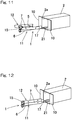
- Fig. 9 to Fig. 18 show a process of accommodating the vertical axis wind power generation device W into the container 2 from an operating state.
- Fig. 9 shows the operating state of the vertical axis wind power generation device W.
- the entire wind turbine 1 is laid down as shown in Fig. 10 .
- the wind turbine 1 is laid down by the support-column tilting mechanism 18 (see Fig. 16 to Fig. 21 ) of the main-shaft-unit folding mechanism 13.
- the main shaft unit 11 is folded by the main-shaft tilting coupling mechanism 19 ( Fig. 22 ) such that the support column 6 and the main shaft 5 are placed upon each other as shown in Fig. 11 .
- the blade units 12 are folded by the blade-unit folding mechanism 14 ( Fig. 27, Fig. 28 ) such that the blade units 12 are placed upon each other as shown in Fig. 24 .
- the wind-turbine folded body which is the thus-folded wind turbine 1 is pushed up on the inclining mount 21 and is accommodated in the container 2 as shown in Fig. 13 .
- the wind turbine mount 17 coupled to the lower end of the inclining mount 21 protrudes from the opening 2a of the container 2, and the wind turbine mount 17 is raised to be accommodated in the container 2 as shown in Fig. 14 .
- the door 10 of the container 2 is closed to complete the accommodation as shown in Fig. 15 . In this way, the wind turbine 1 is accommodated in the folded state in the container 2 when it is transported and stored.
- the wind power generation device W since the wind power generation device is of a vertical axis type, it is possible to efficiently generate electric power even where the device has such a compact size that it can be transported by a single truck and to efficiently generate electric power at low wind speed, unlike that of a horizontal axis type. Further, since the wind power generation device includes the container 2 having a standard dimension for freight transport, and the wind turbine 1 is accommodatable in the folded state in the container 2 together with the power generator 3, it can be treated as a general standard-sized container when transported by ground transport (by trucks or trains), ocean freight and/or air freight and thus is excellent in transportability. For this reason, the power generation device can have a largest possible size within a size restriction for transport, which is advantageous in ensuring power generation capability.
- the device since both the main shaft unit 11 including the support column 6 and the main shaft 5 and the blade units 12 including the blades 7 and the arms 8 for supporting the blades can be folded, the device has greater transportability because it can be transported in the compactly folded state. Further, the device can be easily installed by being unfolded from the folded state at a destination because it is a foldable type. Since not only the blade units 12, but also the main shaft unit 11 including the support column 6 can be folded, the support column 6 can have a relatively large height so as to securely receive a wind force and thus provide sufficient power generation capability, without causing the problem of transportability.
- the main-shaft-unit folding mechanism 13 includes the support-column tilting mechanism 18 which tiltably couples the support column 6 to the wind turbine mount 17, and the support column 6 is tiltable, so that the device can be transported in a more compactly folded state. Further, the main-shaft-unit folding mechanism 13 includes the main-shaft tilting coupling mechanism 19 coupling the main-shaft lower-end supporting member 15 at the upper end of the support column 6 and rotatably supporting the main shaft 5 at the lower end of the main shaft such that the main shaft 5 is tiltable, the main-shaft tilting coupling mechanism being configured to cause the main shaft 5 in a laid state to assume a posture along the support column 6. Thus, the main shaft 5 can be folded so as to assume a posture along the support column 6, so that the device can be transported in a more compactly folded state.
- a support-column fixing part 20 (see Fig. 4, Fig. 5 ) is provided to fix the support column 6 of the wind turbine 1 to the container 2, so that the wind turbine 1 can be easily set up on the container 2, and the container 2 can be used as a foundation for the wind turbine 1.
- the container 2 includes the inclining mount 21 inside the container, the inclining mount being inclined so as to be lowered toward the side of the opening 2a at a longitudinal end of the container and configured to receive the folded body of the wind turbine 1 on the inclining mount, so that the folded body of the wind turbine 1 can slide on the inclining mount 21 due to self-weight so as to be moved out of the container 2 at an installation site, which facilitates installation operation at the site. For example, it is possible to manually take out the folded body of the wind turbine 1 from the container 2, without using heavy equipment.
- the wind turbine In order to accommodate the folded body of the wind turbine 1 in the container 2, the wind turbine is pushed up on the inclining mount 21 so as to be received in the container. Since factories or storage warehouses of vertical axis wind power generation devices W are generally equipped with heavy machinery or the like, a problem is unlikely to arise in accommodating the devices. Where the vertical axis wind power generation device is set up in a disaster area, however, it is preferable that the wind turbine can be easily taken out from the container by human power at an installation site where the environment is not ready for use of heavy equipment. When the vertical axis wind power generation device W is no longer needed and is removed, the traffic situation in the surrounding area is likely be recovered, and heavy equipment can thus be used easily. Alternatively, it is also possible to manually push up the wind turbine on the inclining mount by using a winch or the like from the state of Fig. 39 to accommodate it in the state of Fig. 38 .
- the double door 10 of the container 2 in an opened state may serve as outriggers when the device is set up.
- the door serves as outriggers
- an interposition (not illustrated) is interposed between the door 10 and a surface on which the container 2 is placed, or the door 10 is provided with extensible legs (not illustrated), so that the door 10 can support a load when the container 2 is inclined. Since the door 10 of the container 2 serves as outriggers, it is possible to secure stability of the container 2 as well as the wind turbine 1 fixed thereto against e.g. strong wind and/or earthquake, without providing a dedicated outrigger.
- the door 10 serves as outriggers
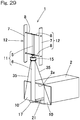
- reinforcing wires 35 such as wire ropes extended between lower ends of tip ends of the double door 10 and the upper end of support column 6 as shown in e.g. Fig. 29 .
- the wind turbine 1 is more stably supported.
- the container 2 may include an inner door 36 disposed an inner side of the door 10 and configured to prevent entry from an outside as shown in Fig. 30 to Fig. 32 .
- the inner door 36 may have an opening 36a with an openable door.
- the inner door 36 is connected to an upper edge of the opening 2a of the container 2 by a hinge 37 such that it can be flipped up to be opened as shown in Fig. 31 and Fig. 32 .
- the door 10 ( Fig. 30 ) is used as outriggers, if nothing is provided, the inside of the container 2 would be left open and may be subjected to entry of rain and wind and/or theft.
- the inner door 36 can prevent such entry and/or theft or the like.
- Fig. 33 to Fig. 37 show a variant of the blade-unit folding mechanism 14.
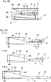
- the blade-unit folding mechanism 14A of this example includes: arm-base-end bending coupling parts 38 each coupling a base end of one arm 8 of the blade units 12 to the main shaft 5 in a bendable manner; and arm-tip-end bending coupling parts 39 each coupling a tip end of one arm 8 to one blade 7 in a bendable manner.
- the blades 7 may be configured to be folded upwardly as shown in Fig. 34A or downwardly as shown in Fig. 34B with respect to the main shaft 5.
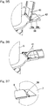
- each arm-base-end bending coupling part 38 is constituted by a hinge 38a and a stopper member 38b configured to be engaged with a base end of one arm 8 coupled to the hinge 38a to regulate an inclination angle of the arm 8 when unfolded.
- the arm 8 and the stopper member 38b are placed one above the other as shown in Fig. 36 and are fixed by nuts and bolts (none of them illustrated) inserted through bolt insertion holes 41, 42 of the arm 8 and the stopper member 38b.
- Fig. 37 shows an example of the arm-tip-end bending coupling part 39.
- the arm-tip-end bending coupling part 39 is constituted by a hinge.
- This constitution also makes it possible to compactly fold the blade units 12.
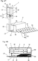
- Fig. 38 to Fig. 44 show an example in which, in the first embodiment, the container 2 is provided with a withdrawing and unfolding mechanism 43 configured to withdraw the folded body of the wind turbine 1, which is constituted by the main shaft unit 11 and the blade units 12 in the folded state and is accommodated on the inclining mount 21, by using the inclining mount 21 while unfolding the folded body and to assist operation of setting up the wind turbine.
- a withdrawing and unfolding mechanism 43 configured to withdraw the folded body of the wind turbine 1, which is constituted by the main shaft unit 11 and the blade units 12 in the folded state and is accommodated on the inclining mount 21, by using the inclining mount 21 while unfolding the folded body and to assist operation of setting up the wind turbine.
- the withdrawing and unfolding mechanism 43 is constituted by: a winch 44 disposed on a floor surface near an inner end portion with respect to the opening 2a inside the container 2; a rope 45 such as a wire rope wound around the winch 44 and having a tip end connected to an intermediate portion of the support column 6 in a lengthwise direction; and a guide roller 46 disposed above the winch 44 inside the container 2 and holding the rope 45 in a hanging manner.
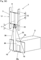
- the folded body of the wind turbine 1 slides down on the inclining mount 17 due to self-weight and moves out from the opening 2a of the container 2 as shown in step A of Fig. 39 .
- the folded body of the wind turbine 1 can be slowly and safely lowered thanks to the use of the winch 44.
- the blade units 12 are unfolded by an operator as shown in step B of Fig. 39
- the main shaft unit 11 is further unfolded such that the support column 6 and the main shaft 5 extend linearly as shown in step C of Fig. 39 .
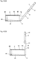
- the wind turbine 1 is gradually raised by winding the winch 44 as shown in Fig. 40A , and the support column 6 is fixed to the container 2 by the support-column fixing part 20 (see Fig. 4, Fig. 5 ) when the wind turbine is completely raised as shown in Fig. 40B .
- Fig. 41 to Fig. 44 show the above process in perspective views.
- the guide roller 46 in the container 2 may be disposed at the opening 2a of the container 2 as shown in Fig. 45 .
- Provision of such a withdrawing and unfolding mechanism 43 can further facilitate and expedite installation operation of the vertical axis wind power generation device W at an installation site.
- Fig. 46 shows an example in which two wind turbines 1 are fixed at opposite ends of the container 2 in the longitudinal direction. Both of the two wind turbines 1 can be folded and accommodated in the container 2 as in the case of the first embodiment.
- the container 2 is provided with openings 2a at the opposite ends, and inclining mounts 21 of Fig. 1 are arranged in opposite directions to each other and juxtaposed in a widthwise direction inside the container 2.
- inclining mounts 21 of Fig. 1 are arranged in opposite directions to each other and juxtaposed in a widthwise direction inside the container 2.
- Fig. 47 to Fig. 52 show an example in which solar panels 51 are added to the first embodiment.
- Each solar panel 51 includes a plurality of photovoltaic cells (not illustrated) arranged in a panel-like manner.
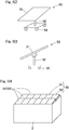
- Each solar panel 51 is disposed on a stand 52 in an inclined manner so as to receive a greater amount of sunlight, and one stand-equipped solar panel 53 is constituted by one solar panel 51 and one stand 52.
- the stand-equipped solar panel 53 may include a caster 54 ( Fig. 48 ). Stand-equipped solar panels 53 are accommodated in the container 2 together with the folded wind turbine 1.
- Each of the stands 52 of the stand-equipped solar panels 53 is shaped such that the solar panels 51 of the respective stand-equipped solar panels 53 can be sequentially stacked on one another in a slightly shifted manner so as to be nested as shown in Fig. 48 .
- the plurality of stand-equipped solar panels 53 are accommodated in the stacked manner in a vacant space lateral to the inclining mount 21 in the container 2.
- the wind turbine 1 is constituted more compactly than that of the first embodiment.
- the control panel 50 ( Fig. 1 ) in the container 2 is additionally provided with a solar charger configured to charge the secondary battery 4 with electric power generated by the respective solar panels 51.
- the respective stand-equipped solar panels 53 are arranged in a juxtaposed manner on the ground around the container 2 at an installation site of the vertical axis wind power generation device W as shown in Fig. 47 and Fig. 49 to Fig. 52 .
- the stand-equipped solar panels 53 may be arranged in a juxtaposed manner on a ceiling plate of the container 2 as shown in Fig. 64 .
- the solar panels 51 are additionally used in this way, it is possible to generate electric power also by sunlight during the duration of sunshine and thus to ensure power generation capability even under windless condition or the like. Since the respective stand-equipped solar panels 53 are separately disposed from the container 2, there is no need to worry about the direction of an installation site of the container 2.
- Fig. 54 to Fig. 63 show various examples of the stand-equipped solar panel 53.
- the stand 52 includes an extensible leg portion 52a, so that the inclination angle of the solar panel 51 can be adjusted.
- Fig. 65 to Fig. 70 show still another embodiment of the present invention.
- the embodiment shown in these figures has the same features as those of the first embodiment, unless otherwise specifically described.
- the container 2 is provided with a linear guiding device 71 configured to liftably guide the wind turbine 1 between a use position (a position as shown in Fig. 65 ) in which the blades 7 project upward from a height range of the container 2 and an accommodation position (a position as shown in Fig. 66 ) in which the blades 7 are accommodated within the height range of the container 2.
- a lifting device 75 configured to lift and lower the wind turbine 1 is provided.
- the container 2 is a standard-sized container which can be transported by ground transport or air freight in order to transport a system for supplying electric power in disaster areas affected by hazards. A 12-feet container is assumed to be used in the present invention.
- the linear guiding device 71 is constituted by a linear guide of a rolling type (also referred to as a linear rolling bearing) or the like and is attached to an inner surface of a wall 2b of one end of the container 2.
- the linear guiding device 71 is constituted by a fixed rail 72 attached to the wall 2b of the container 2 along the vertical direction and a plurality of upper and lower movable members 73 assembled to the fixed rail so as to be linearly movable in the vertical direction, and the movable members 73 are attached to the lower portion of the support column 6 of the wind turbine 1.
- the lifting device 75 is a lifting winder (e.g., a winch) capable of winding a winding member 76 connected to an upper portion of the container 2 and the lower portion of the support column 6 to lift and lower the wind turbine 1 as shown in Fig. 67A .
- the winding member 76 may be, for example, a rope, a belt, or a chain which is provided with hooks 77, 78 at its upper and lower ends.
- the upper hook 77 is engaged with a receiving metal fitting 79 provided to the upper portion of the container 2, and the lower hook 78 is engaged with a receiving metal fitting 80 provided to the lower end of the support column 6.
- the lifting device 75 is of a manual winding type in which a drum around which the winding member 76 is wound is rotated by a handle or the like (not illustrated).
- the lifting device 75 may be of a motorized type in which the drum is rotated by an electric motor 81 (see Fig. 67B ).
- an electric motor 81 is also illustrated by an imaginary line.
- the container 2 has a ceiling 2c formed with an upper opening 83 for moving the wind turbine 1 in and out therethrough.
- a door (not illustrated) is provided to the upper opening 83 such that it can be opened and closed as needed. The door can be closed when the wind turbine 1 is accommodated in the container 2 and be opened when the wind turbine 1 is unfolded to the use position.
- the upper opening 83 is shaped in a rectangular shape matching an end face of the container 2 and is sized to define a minimum opening area such that the rotary blade 9 constituted by the two blades 7 of the wind turbine 1 can be moved in and out only when the rotary blade has a rotation phase in which it matches the end face of the container 2.
- the support column 6 of the wind turbine 1 is attached to the linear guiding device 71 vertically disposed on the wall 2b inside the container 2.
- the wind turbine 1 can be easily moved up on the container 2 by manually winding the winding member 76 connecting the hook 77 engaged with the upper portion of the container 2 and the hook 78 engaged with the lower portion of the support column 6 of the wind turbine 1 by the lifting device 75.
- the ceiling 2c of the container 2 has the upper opening 83 which can be closed when the wind turbine 1 is accommodated and be opened when the wind turbine 1 is unfolded as needed in a doorlike manner.
- An inner lid 84 ( Fig.
- the inner lid 84 may be provided to protect the inside of the container 2 against the wind and rain even when the wind turbine 1 is unfolded.
- the inner lid 84 may be attached to the support column 6 of the wind turbine 1. Thus, the inner lid 84 is closed from the inside at the same time as the wind turbine 1 is moved up, so that the container 2 is closed tightly.
- the lifting device 75 may be a motorized winder. This makes it possible to unfold and accommodate the wind turbine 1 only by operating a switch.
- a limit switch or the like may be provided to the support column 6 and the container 2 to additionally provide a function that the motorized lifting device is automatically stopped when unfolding and accommodating are completed.
- the lifting device 75 may also serve as a support-column fixing part for fixing the support column 6 of the wind turbine 1 to the container 2 together with the linear guiding device 71, there may be a dedicated support-column fixing for fixing the wind turbine 1 in a moved-up state to the container 2 if needed.
- Fig. 67B shows an example in which a bolt is used as the support-column fixing part 85 to fix the support column 6 of the wind turbine 1 and the container 2.
- a fixing metal fitting 86 fixed to the support column 6 is fixed by a bolt 88 to a container-side fixing metal fitting 87 which is integrated with the container 2.
- the wind turbine 1 is disposed inside the container 2 in the above embodiment, the wind turbine 1 may be fixed outside the container 2 if needed, as shown in e.g. Fig. 69 and Fig. 70 .
- a space inside the container 2 is widened, so that the inner space can be effectively used.
- the wind turbine 1 is shaped and dimensioned such that it can be accommodated in the container 2 as it is or in a folded or disassembled state. This makes it possible to immediately accommodate the wind turbine 1 when a large-scale typhoon approaches in order to avoid damage to the wind turbine 1 due to the typhoon.
- the wind turbine 1 is attached outside the container 2, there is a risk that the wind turbine 1 may be damaged when the container 2 is moved with the wind turbine 1 being attached thereto. Therefore, when moving the container 2, the wind turbine 1 is detached from the linear guiding device 71 and is accommodated in the container by using a non-illustrated dolly or the like. In such a case, since there is a step between a floor of the container and the ground, it is necessary to separately provide a slope or the like. Further, it is very difficult to push the dolly carrying the wind turbine 1, which is a heavy object, on the slope up to the floor. In the case where the wind turbine disposed in the container is set up outside the container, it is also necessary to provide a slope and lower a dolly carrying the wind turbine from the container.
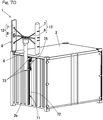
- one door 10A is provided with a wind-turbine holding part Ha configured to hold the wind turbine 1 in the accommodated state in the container 2 along an inner side of the door 10A of the container 2.
- one door 10A is provided with a water-turbine holding part Hb configured to hold the compact hydropower generation device 60 including the water turbine 62 in the accommodated state in the container 2 along an inner side of the door 10A of the container 2.
- the container 2 of the present embodiment has the openings 2a on opposite sides and double doors 10A, 10A for opening and closing the respective openings 2a.
- the wind-turbine holding part Ha includes a fixing metal fitting 86 fixed to the longitudinal lower portion of the support column 6 and a non-illustrated plurality of bolts inserted through respective bolt holes 86a in the fixing metal fitting 86 and screwed into the door 10A ( Fig. 74B ) of the container 2.
- the fixing metal fitting 86 is provided with a to-be-engaged portion 86b which can be engaged with the lower hook 78 of the winding member 76 (see Fig. 67A ).
- Fig. 74A and Fig. 74B when the door 10A is opened to take out the wind turbine 1 held along the inner side of the door 10A from the container, the wind turbine 1 can be received on a dolly or the like without using a slope or the like, and the wind turbine 1 can be easily attached to the linear guiding device 71 outside container 2 as shown in e.g. Fig. 69 and Fig. 70 . Also in the case where the wind turbine 1 is removed from an installation position and is accommodated into the container, when the door 10A is opened, the wind turbine 1 can be easily held along the inner side of the door 10A by the wind-turbine holding part Ha without using a slope or the like as shown in Fig. 74B .
- the water-turbine holding part Hb includes: two supporting members 66, 66 supporting base mounts Kd, Kd at opposite ends of the water turbine 62 in the widthwise direction; and a plurality sets of bolts and nuts 67 inserted through oblong holes defined in the base mounts Kd, Kd and fastened to the respective supporting members 66.
- the two supporting members 66, 66 are fixed to the inside of the door 10A of the container 2 in a parallel manner and extend in the vertical direction with respect to a wall surface across a predetermined gap.
- Each of the supporting members 66 may be constituted by, for example, an equilateral angle steel (such as a so-called angle).
- the water turbine 62 when the door 10A is opened to take out the water turbine 62 held along the inner side of the door 10A from the container, the water turbine 62 can be received on a dolly or the like and be moved to a desired installation position without using a slope or the like. Also in the case where the water turbine 62 is removed from an installation position and is accommodated into the container, the water turbine 62 can be easily held along the inner side of the door 10A by the water-turbine holding part Hb without using a slope or the like.
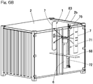
- the wind-turbine holding part Ha may include a link mechanism 68 which serves to change the position of the wind turbine 1 from the inner side of the door 10A to a position distant from the inner side of the door 10A.
- the link mechanism 68 includes a bracket 69, a first link plate L1, and a second link plate L2.
- the bracket 69 is fixed to an inner opening edge of the door 10A, and the bracket 69 supports one longitudinal end of the first link plate L1 such that it is rotatable about a vertical axis.
- the other longitudinal end of the first link plate L1 supports one longitudinal end of the second link plate L2 such that it is rotatable about the vertical axis.
- the other longitudinal end of the second link plate L2 is coupled to the support column 6.
- the position of the wind turbine 1 can be changed by the link mechanism 68 as shown in Fig. 77 , from the inner side of the door 10A to a position distant from the inner side of the door 10A, i.e., to a position on the side of one longitudinal end of the container 2 in the example of Fig. 77 .
- This makes it possible to directly move the wind turbine 1 and fix it to a desired installation position by the bolts, without being unloaded from the door 10A.
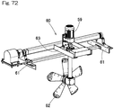
- Fig. 71 and Fig. 72 show an embodiment of a container-accommodated hydropower generation device.
- the container-accommodated hydropower generation device includes a container 2 having a standard dimension for freight transport and a plurality of compact hydropower generation devices 60 capable of being installed in a water channel and being accommodated in and removed from the container 2.
- Each of the compact hydropower generation devices 60 is accommodated in the container 2 together with a jig 64 for transport.
- each compact hydropower generation device 60 includes: a pair of base mounts 61, 61 disposed on water channel walls on opposite sides of the water channel (not illustrated); a water turbine 62; a rotary frame 63 supporting the water turbine 62 and supported by the pair of base mounts 61, 61 in a vertically rotatable manner; and a power generator 59 configured to generate electric power by rotation of the water turbine 62.
- the rotary frame 63 can be rotated between a use posture in which the water turbine 62 is submerged under the surface of the water in the water channel and a raised posture in which the water turbine is rest above the water.
- the compact hydropower generation device has excellent transportability because it is accommodated in the container having a standard dimension.
- each of the application aspects providing the above-described vertical axis wind power generation device which does not require the container and the support-column fixing part.
- the application aspects include aspects 1 to 8 below.
- the vertical axis wind power generation device according to any of the application aspects also provides the effects that since both the main shaft unit including the support column and the main shaft as well as the blade units including the blades and the arms for supporting the blades can be folded, the device has excellent transportability because it can be transported in the folded state, and can be easily installed by being unfolded from the folded state at a destination because it is a foldable type.
- a vertical axis wind power generation device including:
- the vertical axis wind power generation device as recited in aspect 1, wherein the main-shaft-unit folding mechanism includes a support-column tilting mechanism tiltably coupling the support column to a wind turbine mount.
- the vertical axis wind power generation device as recited in aspect 1 or 2, wherein the main-shaft-unit folding mechanism includes a main-shaft tilting coupling mechanism coupling a main-shaft lower-end supporting member located at an upper end of the support column and rotatably supporting the main shaft at a lower end of the main shaft such that the main shaft is tiltable, the main-shaft tilting coupling mechanism being configured to cause the main shaft in a laid state to assume a posture along the support column.
- the blade-unit folding mechanism includes rotary coupling members provided to the respective blades and disposed around the main shaft so as to be rotatable, the rotary coupling members being coupled to base ends of the respective arms.
- the vertical axis wind power generation device as recited in any of aspect 1 to 3, wherein the blade-unit folding mechanism includes arm-base-end bending coupling parts coupling base ends of the arms to the main shaft in a bendable manner and arm-tip-end bending coupling parts coupling tip ends of the arms to the blades in a bendable manner.
- the vertical axis wind power generation device as recited in any of aspect 1 to 5, including a container configured to accommodate the main shaft unit and the blade units in the folded state and housing the power generator disposed in the container, and
- a support-column fixing part configured to fix the support column of the main shaft unit taken out from the container in a raised posture.
- the vertical axis wind power generation device as recited in aspect 6, including an inclining mount inside the container, the inclining mount being inclined so as to be lowered toward an opening side at a longitudinal end of the container and configured to carry the main shaft unit and the blade units in the folded state on the inclining mount such that the folded body can be moved in and out through an opening.
- the vertical axis wind power generation device as recited in aspect 7, wherein the container includes a withdrawing and unfolding mechanism configured to withdraw the main shaft unit and the blade units in the folded state, which are accommodated on the inclining mount, by using the inclining mount while unfolding the main shaft unit and the blade units and to assist operation of setting up the main shaft unit and the blade units.
- a withdrawing and unfolding mechanism configured to withdraw the main shaft unit and the blade units in the folded state, which are accommodated on the inclining mount, by using the inclining mount while unfolding the main shaft unit and the blade units and to assist operation of setting up the main shaft unit and the blade units.
Landscapes
- Engineering & Computer Science (AREA)
- Mechanical Engineering (AREA)
- Chemical & Material Sciences (AREA)
- Combustion & Propulsion (AREA)
- General Engineering & Computer Science (AREA)
- Life Sciences & Earth Sciences (AREA)
- Sustainable Development (AREA)
- Sustainable Energy (AREA)
- Power Engineering (AREA)
- Wind Motors (AREA)
Abstract
Description
- This application is based on and claims Convention priority to
Japanese patent application No. 2018-190582, filed October 9, 2018 Japanese patent application No. 2018-190583, filed October 9, 2018 Japanese patent application No. 2019-072001, filed April 4, 2019 Japanese patent application No. 2019-079604, filed April 18, 2019 - The present invention relates to a vertical axis wind power generation device capable of being easily transported and simply installed as a power supply source in non-electrified areas of developing countries and/or disaster areas affected by hazards and to a container-accommodated hydropower generation device having excellent transportability.
-
Patent Documents 1 to 4 have proposed wind power generation devices in consideration of easy transport and simple installation.Patent Document 1 describes that solar panels serving as side surfaces of a transport box are unfolded upward so as to be raised on a frame of the box in an inclined manner and that a wind power generator is attached to a side of the frame.Patent Documents Patent Document 4 describes that blades of a wind turbine of a vertical axis wind power generation device can be folded along a main shaft. -
- [Patent Document 1]
JP Patent No. 4791353 - [Patent Document 2]
JP Patent No. 4563179 - [Patent Document 3]
JP Patent No. 5557858 - [Patent Document 4]
JP Laid-open Patent Publication No. 2017-218998 - Important requirements of power source systems for supplying electric power in non-electrified areas of developing countries and/or disaster areas affected by hazards include easy transport, simple installation, and power generation capability.
-
Patent Document 1 assumes that a unit is dimensioned as a 1-m cube, so that sufficient power generation capability cannot not be achieved. Further, although the size of the 1-m cube is advantageous in transport in that the unit can be transported even by a small truck, in the case where more than one units are loaded in and transported by a truck, they do not tightly fit within the dimensions of a back of the truck and leave a useless space, which is uneconomical.Patent Documents Patent Documents 1 to 3, however, all employ horizontal axis wind turbines, so that they have poor power generation efficiency when they have compact configurations. Where a wind turbine has a compact size in consideration of transportability to and easy installation in non-electrified areas of developing countries and/or disaster areas affected by hazards, the wind turbine has poor power generation efficiency and insufficient power generation capability. In addition, the horizontal axis wind turbines are hardly rotated at low wind speed, so that it may not be possible to find an installation location in which electric power can be effectively generated in the case where they are installed in limited spaces in disaster areas. -
Patent Document 4 does not have the problem of the horizontal axis wind turbines because it employs a vertical axis wind turbine, and provides excellent transportability and installation because the blades can be folded. However, the document does not disclose how the folded wind turbine is transported. - An object of the present invention is to provide a vertical axis wind power generation device capable of being easily transported and simply installed and providing sufficient power generation capability even where it has a compact configuration.
- Another object of the present invention is to provide a container-accommodated hydropower generation device which is a compact hydropower generation device having improved transportability.
- A vertical axis wind power generation device of the present invention includes:
- a wind turbine of a vertical axis type including a support column, a main shaft disposed on an upper portion of the support column so as to be rotatable about a vertical axis, a plurality of blades extending in a vertical direction around the main shaft and coupled to the main shaft through arms;
- a power generator configured to generate electric power by rotation of the main shaft; and
- a container having a standard dimension for freight transport, wherein
- the wind turbine is accommodatable in the container together with the power generator, and
- the container is provided with a support-column fixing part configured to fix the support column of the wind turbine to the container.
- According to the constitution, since the wind power generation device is of a vertical axis type, it is possible to efficiently generate electric power even where the device has such a compact size that it can be transported by a single truck and to efficiently generate electric power at low wind speed, unlike that of a horizontal axis type. Further, since the wind power generation device includes a container having a standard dimension for freight transport, and the wind turbine is accommodatable in the container together with the power generator, it can be treated as a general standard-sized container when transported by ground transport (by trucks or trains), ocean freight and/or air freight and thus is excellent in transportability. For this reason, the power generation device can have a largest possible size within a size restriction for transport, which is advantageous in ensuring power generation capability. In order to set up the wind turbine, the container is provided with a support-column fixing part for fixing the support column of the wind turbine thereto, so that the wind turbine can be easily set up on the container, and the container can be used as a foundation for the wind turbine.
- Thus, it is possible to easily transport the wind power generation device, to install it easily and speedily, and to ensure power generation capability even where it has a compact configuration. This makes it possible to meet a demand for electric power in non-electrified areas and/or disaster areas affected by hazards. It should be noted that the "container having a standard dimension for freight transport" may have a dimension meeting at least a national standard for container transport or a dimension meeting, for example, a standard established by the national administrative body or international authorities such as the International Organization for Standardization (ISO).
- In the present invention, the vertical axis wind turbine may be foldable or disassemblable. Where the wind turbine is foldable or disassemblable, a larger vertical axis wind turbine can be easily transported. Although the vertical axis wind turbine may be of an assembled type which allows disassembly of the wind turbine, the vertical axis wind turbine of a foldable type can further facilitate installation operation and can be installed speedily.
- In the present invention, the wind turbine may be accommodatable in a folded or disassembled state in the container. Where the wind turbine is accommodatable in a folded or disassembled state in the container, a larger vertical axis wind turbine can be accommodated in the container.
- Where the vertical axis wind turbine is foldable, the container may include an inclining mount inside the container, the inclining mount being inclined so as to be lowered toward an opening side at a longitudinal end of the container and configured to carry a folded body of the wind turbine on the inclining mount such that the folded body can be moved in and out through an opening. Thus, the container includes the inclining mount thereinside and accommodates the folded body of the wind turbine on the inclining mount, so that the folded body of the wind turbine can slide on the inclining mount due to self-weight so as to be moved out of the container at an installation site, which facilitates installation operation at the site. For example, it is possible to manually take out a folded wind turbine from a container without using heavy equipment.
- In order to accommodate the wind turbine in the container, the wind turbine is pushed up on the inclining mount so as to be received in the container. Since factories or storage warehouses of vertical axis wind power generation devices are generally equipped with heavy machinery or the like, a problem is unlikely to arise in accommodating the devices. Where the vertical axis wind power generation device is set up in a disaster area, however, it is preferable that the wind turbine can be easily taken out from the container by human power at an installation site where the environment is not ready for use of heavy equipment. When the vertical axis wind power generation device is no longer needed and is removed, the traffic situation in the surrounding area is likely be recovered, and heavy equipment can thus be used easily. Alternatively, it is also possible to manually push up the wind turbine on the inclining mount by using a winch or the like from the state of
Fig. 39 to accommodate it in the state ofFig. 38 . - Where the container includes the inclining mount, the container may include a withdrawing and unfolding mechanism configured to withdraw the folded body of the wind turbine by using the inclining mount while unfolding the folded body and to assist operation of setting up the wind turbine. Where the container includes such a withdrawing and unfolding mechanism, the installation operation can further be facilitated and expedited. In the case where the vertical axis wind turbine has an overall length shorter than that of a longer side of the container, it can be accommodated without being folded, so that the installation operation of such a wind turbine can be more speedily as compared with that of a folded type.
- In the present invention, the container may include a double door configured to open and close the opening at the longitudinal end of the container, and the door in an opened state may serve as outriggers. Since the door of the container serves as outriggers, it is possible to secure stability of the container and the wind turbine fixed thereto against e.g. strong wind and/or earthquake, without providing dedicated outriggers.
- Where the door serves as outriggers, the container may include an inner door disposed an inner side of the door and configured to prevent entry from an outside. Where the door is used as outriggers, if nothing is provided, the inside would be left open and may be subjected to entry of rain and wind and/or theft. The inner door can prevent such entry and/or theft or the like.
- In the present invention, there may be a solar panel assembled with a stand so as to be installable outside or on the container and configured to photovoltaically generate electric power and a secondary battery configured to store the generated electric power, the solar panel and the secondary battery being accommodatable in the container together with the wind turbine in the folded or disassembled state. In the case of this constitution, it is possible to perform wind power generation as well as solar power generation. Since the solar panel is assembled with the stand, it is only necessary to place the solar panel outside or on the container to install it. In the case where the device includes a plurality of solar panels assembled with stands, the solar panels may be shaped such that they can be sequentially stacked in a nesting manner when they are accommodated in the container, so that a large number of solar panels can be accommodated in the container.
- In the present invention, the vertical axis wind power generation device may include: a main-shaft-unit folding mechanism configured to allow the main shaft unit including the support column and the main shaft to be folded; and a blade-unit folding mechanism configured to allow blade units, which are constituted by the blades and the arms, to be folded along the main shaft unit in a folded state. According to this constitution, since both the main shaft unit including the support column and the main shaft as well as the blade units including the blades and the arms for supporting the blades can be folded, the device has excellent transportability because it can be transported in the folded state, and can be easily installed by being unfolded from the folded state at a destination because it is a foldable type. Since not only the blade units, but also the main shaft unit including the support column can be folded, the support column can have a relatively large height so as to securely receive a wind force and thus provide sufficient power generation capability, without causing the problem of transportability. This makes it possible to easily transport the wind power generation device, to install it easily and speedily, and to ensure power generation capability even where it has a compact configuration. Thus, it is possible to meet a demand for electric power in non-electrified areas and/or disaster areas affected by hazards.
- In the present invention, the main-shaft-unit folding mechanism may include a support-column tilting mechanism tiltably coupling the support column to a wind turbine mount. Where the support column is tiltable, the device can be transported in a more compactly folded state and thus has greater transportability.
- In the present invention, the main-shaft-unit folding mechanism may include a main-shaft tilting coupling mechanism coupling a main-shaft lower-end supporting member located at an upper end of the support column and rotatably supporting the main shaft at a lower end of the main shaft to the upper end of the support column such that the main shaft is tiltable, the main-shaft tilting coupling mechanism being configured to cause the main shaft in a laid state to assume a posture along the support column. Thus, the main shaft can be folded so as to assume a posture along the support column, so that the device can be transported in a more compactly folded state and thus has greater transportability.
- In the present invention, the blade-unit folding mechanism may include rotary coupling members provided to the respective blades and disposed around the main shaft so as to be rotatable, the rotary coupling members being coupled to base ends of the respective arms. In the case of this constitution, the rotary coupling members can be rotated about the main shaft such that the plurality of blades are folded in an overlapped state, which makes it possible to compactly fold the device.
- In the present invention, the blade-unit folding mechanism may include arm-base-end bending coupling parts coupling base ends of the arms to the main shaft in a bendable manner and arm-tip-end bending coupling parts coupling tip ends of the arms to the blades in a bendable manner. In the case of this constitution, the blade unit can be folded such that the respective blades are arranged along the main shaft by bending the arms, which also makes it possible to compactly fold the device.
- In the present invention, the door may include a wind-turbine holding part configured to hold the wind turbine in the accommodated state in the container such that the wind turbine extends along an inner side of the door of the container. In the case where the wind turbine is removed from an installation position and is accommodated into the container by using a dolly or the like when moving the wind turbine, the following problems arise. Since there is a step between a floor of the container and the ground, it is necessary to separately provide a slope etc. Further, it is very difficult to push the dolly carrying the wind turbine, which is a heavy object, on the slope up to the floor. In the case where the wind turbine disposed in the container is set up outside the container, it is also necessary to provide a slope and lower a dolly carrying the wind turbine from the container.
- As a means for solving the problems, the door is provided with the wind-turbine holding part configured to hold the wind turbine in the accommodated state in the container such that the wind turbine extends along the inner side of the door of the container. Thus, when the door is opened to take out the wind turbine held along the inner side of the door from the container, the wind turbine can be received on a dolly or the like and be moved to a desired installation position without using a slope or the like. Also in the case where the wind turbine is removed from an installation position and accommodated into the container, it is possible to open the door and to easily hold the wind turbine along the inner side of the door by the wind-turbine holding part without using a slope or the like.
- In the invention in which the wind-turbine holding part is provided, the wind-turbine holding part may have a function of changing a position of the wind turbine from the inner side of the door to a position distant from the inner side of the door. Although, when the door is opened, the wind turbine held along the inner side of the door can be easily taken out from the container, it is sometimes difficult to carry it on a dolly depending on road surface conditions, such as gravel or soil roads. Thus, the wind-turbine holding part makes it possible to change the position of the wind turbine from the inner side of the door to a position distant from the inner side of the door, so that the wind turbine can be directly moved and fixed to a desired installation position, without being unloaded from the door.
- The door may include a water-turbine holding part configured to hold a water turbine in an accommodated state in the container such that the water turbine extends along the inner side of the door of the container. In this case, when the door is opened to take out the water turbine held along the inner side of the door from the container, the water turbine can be received on a dolly or the like and be moved to a desired installation position without using a slope or the like. Also in the case where the water turbine is removed from an installation position and accommodated into the container, it is possible to easily hold the water turbine along the inner side of the door by the water-turbine holding part without using a slope or the like.
- In the present invention, the container may be provided with a linear guiding device configured to liftably guide the wind turbine between a use position at which the blades project upward from a height range of the container and an accommodation position at which the blades are accommodated within the height range of the container. In this way, where the wind turbine can be lifted and lowered by the linear guiding device, it is possible to easily unfold the wind turbine to a useable state at a destination and to easily shelter the wind turbine during removal of the wind turbine or high wind events.
- Where the wind turbine is liftable, the vertical axis wind power generation device may include a lifting device of a winding type configured to wind a winding member connected to an upper portion of the container and a lower portion of the support column such that the wind turbine can be lifted and lowered. In the case of this constitution, the lifting device can be operated to lift or lower the wind turbine, so that the operation of lifting and lowering the wind turbine is further facilitated. Since the lifting winder is a feature for winding the winding member connected to the upper portion of the container and the lower portion of the support column, it may have a simple constitution. For example, it may be a common winch or the like. The winding member may be a chain, a rope, a belt or the like. Where the lifting device configured to lift and lower the wind turbine such as the lifting winder is provided, the support-column fixing part may be provided only for fixing purpose separately from the lifting device or the like, or the lifting device and/or the linear guiding device may also serve as the support-column fixing part. Where the linear guiding device is provided, the motion is limited to directions other than the vertical direction. Thus, because the lifting device restricts a vertical motion, the wind turbine is fixed to the container.
- The lifting device may be of an electrically-powered type which is configured to be driven by an electric motor to perform winding operation. Although the lifting winder may be of a manual type, where it is of an electrically-powered type, the wind turbine can be more easily lifted and lowered through an operation of a switch.
- Where the wind turbine is liftable, the container may have a ceiling surface having an upper opening configured to allow the wind turbine to move in and out therethrough, and the support column may be provided with an inner lid configured to tightly close the upper opening when the wind turbine is raised. Where the support column is provided with the inner lid, the upper opening of the container is closed by the inner lid when the wind turbine is raised to the use position, so that a dedicated operation for closing the inner lid is not necessary.
- A container-accommodated hydropower generation device of the present invention includes: a container having a standard dimension for freight transport; and a compact hydropower generation device capable of being installed in a water channel and being accommodated in and removed from the container. According to the hydropower generation device having this constitution, the compact hydropower generation device is accommodated in the container having the standard dimension, so that it has excellent transportability.
- Any combination of at least two constructions, disclosed in the appended claims and/or the specification and/or the accompanying drawings should be construed as included within the scope of the present invention. In particular, any combination of two or more of the appended claims should be equally construed as included within the scope of the present invention.
- The present invention will be more clearly understood from the following description of preferred embodiments thereof, when taken in conjunction with the accompanying drawings. However, the embodiments and the drawings are given only for the purpose of illustration and explanation, and are not to be taken as limiting the scope of the present invention in any way whatsoever, which scope is to be determined by the appended claims. In the accompanying drawings, like reference numerals are used to denote like parts throughout the several views. In the figures,
-
Fig. 1 is a perspective view illustrating a use state of a vertical axis wind power generation device according to a first embodiment of the present invention; -
Fig. 2 is a perspective view illustrating an accommodated state of the vertical axis wind power generation device, with its door being opened; -
Fig. 3 is a perspective view of an inclining mount disposed in a container of the vertical axis wind power generation device; -
Fig. 4 is a perspective view illustrating the use state of the vertical axis wind power generation device as seen from a back side; -
Fig. 5 is an enlarged perspective view of part V ofFig. 4 ; -
Fig. 6 is a plan view of the vertical axis wind power generation device in the accommodated state, with the door being opened; -
Fig. 7 is a sectional view along line VII-VII ofFig. 6 ; -
Fig. 8 is a sectional view along line VIII-VIII ofFig. 6 ; -
Fig. 9 is a perspective view illustrating the vertical axis wind power generation device before being accommodated in an accommodation process; -
Fig. 10 is a perspective view illustrating a step of laying a support column during the accommodation process of the vertical axis wind power generation device; -
Fig. 11 is a perspective view illustrating a step of folding a main shaft unit during the accommodation process of the vertical axis wind power generation device; -
Fig. 12 is a perspective view illustrating a step of folding blade units during the accommodation process of the vertical axis wind power generation device; -
Fig. 13 is a perspective view illustrating a step of accommodating a wind-turbine folded body during the accommodation process of the vertical axis wind power generation device; -
Fig. 14 is a perspective view illustrating a step of raising a wind turbine mount during the accommodation process of the vertical axis wind power generation device; -
Fig. 15 is a perspective view illustrating a step of closing the door during the accommodation process of the vertical axis wind power generation device; -
Fig. 16 is a perspective view illustrating a raised state of the wind turbine mount of the vertical axis wind power generation device; -
Fig. 17 is a perspective view illustrating a laid state of the wind turbine mount; -
Fig. 18 is a perspective view illustrating a step of coupling the support column to the wind turbine mount; -
Fig. 19 is a perspective view illustrating a step of engaging an overhanging hook of the wind turbine mount; -
Fig. 20 is a perspective view illustrating a step of raising the support column on the wind turbine mount; -
Fig. 21 is a perspective view illustrating a step of fixing the support column to the wind turbine mount; -
Fig. 22 is a perspective view of a main-shaft tilting coupling mechanism of the vertical axis wind power generation device; -
Fig. 23 is a perspective view illustrating an unfolded state of the blade units of the vertical axis wind power generation device; -
Fig. 24 is a perspective view illustrating a folded state of the blade units of the vertical axis wind power generation device; -
Fig. 25 is a plan view illustrating an unfolded state of the blade units of the vertical axis wind power generation device; -
Fig. 26 is a plan view illustrating a folded state of the blade units of the vertical axis wind power generation device; -
Fig. 27 is a perspective view illustrating an unfolded state of a blade-unit folding mechanism of the vertical axis wind power generation device; -
Fig. 28 is a perspective view illustrating a folded state of the blade-unit folding mechanism of the vertical axis wind power generation device; -
Fig. 29 is a perspective view showing an example in which the door of the vertical axis wind power generation device is used as outriggers; -
Fig. 30 is a perspective view of the container of the vertical axis wind power generation device, which additionally includes an inner door; -
Fig. 31 is a cutaway front view of the container of the vertical axis wind power generation device, which additionally includes the inner door; -
Fig. 32 is an enlarged sectional view of part XXXII ofFig. 31 ; -
Fig. 33 is a front view showing an example in which a variant of the blade-unit folding mechanism is provided to the blade units; -
Fig. 34A is a front view showing an example of the folded state of the blade-unit folding mechanism according to the variant; -
Fig. 34B is a front view showing another example of the folded state of the blade-unit folding mechanism according to the variant; -
Fig. 35 is a perspective view illustrating a folded state of arm-base-end bending coupling parts of the blade-unit folding mechanism; -
Fig. 36 is a perspective view of the arm-base-end bending coupling parts before being folded; -
Fig. 37 is a perspective view of an arm-tip-end bending coupling part of the blade-unit folding mechanism before being folded; -
Fig. 38 is a cutaway front view illustrating an accommodated state of an embodiment in which the vertical axis wind power generation device is provided with a withdrawing and unfolding mechanism; -
Fig. 39 is a cutaway front view illustrating a step of unfolding the vertical axis wind power generation device; -
Fig. 40A is a cutaway front view illustrating a step of raising the support column of the vertical axis wind power generation device; -
Fig. 40B is a cutaway front view illustrating a completely raised state of the support column; -
Fig. 41 is a perspective view illustrating a step of withdrawing the wind-turbine folded body of the vertical axis wind power generation device; -
Fig. 42 is a perspective view illustrating a step of unfolding the blade units of the vertical axis wind power generation device; -
Fig. 43 is a perspective view illustrating a step of unfolding the main shaft unit of the vertical axis wind power generation device; -
Fig. 44 is a perspective view illustrating a step of raising the main shaft unit of the vertical axis wind power generation device; -
Fig. 45 is a sectional view illustrating a variant of the withdrawing and unfolding mechanism of the vertical axis wind power generation device; -
Fig. 46 is a front view of yet another embodiment of the vertical axis wind power generation device; -
Fig. 47 is a perspective view of an embodiment of the vertical axis wind power generation device in which solar panels are provided; -
Fig. 48 is a sectional view illustrating an accommodated state of the vertical axis wind power generation device; -
Fig. 49 is a plan view illustrating the use state of the vertical axis wind power generation device; -
Fig. 50 is a front view illustrating the use state of the vertical axis wind power generation device; -
Fig. 51 is a left-side view illustrating the use state of the vertical axis wind power generation device; -
Fig. 52 is a right-side view illustrating the use state of the vertical axis wind power generation device; -
Fig. 53 is a perspective view of still another embodiment of the vertical axis wind power generation device in which solar panels are provided; -
Fig. 54 is a perspective view showing an example of a stand-equipped solar panel used in the vertical axis wind power generation device; -
Fig. 55 is a plan view showing another example of the stand-equipped solar panel; -
Fig. 56 is a plan view showing yet another example of the stand-equipped solar panel; -
Fig. 57 is a front view showing still another example of the stand-equipped solar panel; -
Fig. 58 is a perspective view showing yet another example of the stand-equipped solar panel; -
Fig. 59 is a side view showing still another example of the stand-equipped solar panel; -
Fig. 60 is a plan view showing yet another example of the stand-equipped solar panel; -
Fig. 61 is a front view showing still another example of the stand-equipped solar panel; -
Fig. 62 is a perspective view showing yet another example of the stand-equipped solar panel; -
Fig. 63 is a front view showing still another example of the stand-equipped solar panel; -
Fig. 64 is a perspective view showing an example in which the stand-equipped solar panels are disposed on the container; -
Fig. 65 is a perspective view illustrating an accommodated state of a wind turbine of a vertical axis wind power generation device according to yet another embodiment of the present invention; -
Fig. 66 is a perspective view illustrating a use state of the wind turbine of the vertical axis wind power generation device; -
Fig. 67A is a perspective view illustrating a lifting device of the vertical axis wind power generation device; -
Fig. 67B is a perspective view illustrating a support-column fixing part of the vertical axis wind power generation device; -
Fig. 68 is a perspective view illustrating an accommodated state of a wind turbine of a vertical axis wind power generation device according to still another embodiment of the present invention; -
Fig. 69 is a perspective view illustrating an accommodated state of a wind turbine of a vertical axis wind power generation device according to yet another embodiment of the present invention; -
Fig. 70 is a perspective view illustrating a use state of the wind turbine of the vertical axis wind power generation device; -
Fig. 71 is a perspective view illustrating an accommodated state of a container-accommodated hydropower generation device according to an embodiment of the present invention; -
Fig. 72 is a perspective view showing an example of the compact hydropower generation device; -
Fig. 73A is a plan view of an inside of a container, which illustrates an accommodated state of a wind turbine of a vertical axis wind power generation device according to still another embodiment of the present invention; -
Fig. 73B is a front view illustrating an accommodated state of a wind turbine of a vertical axis wind power generation device according to yet another embodiment of the present invention; -
Fig. 74A is a plan view illustrating the container of the vertical axis wind power generation device, with its door being opened; -
Fig. 74B is a front view illustrating the container of the vertical axis wind power generation device, with the door being opened; -
Fig. 75 is a partially enlarged view of a wind-turbine holding part of the vertical axis wind power generation device; -
Fig. 76 is a partially enlarged view of a water-turbine holding part of the vertical axis wind power generation device; and -
Fig. 77 is a plan view of a vertical axis wind power generation device according to still another embodiment of the present invention. - A vertical axis wind power generation device W according to a first embodiment of the present invention will be described with reference to
Fig. 1 to Fig. 28 . InFig. 1 , the vertical axis wind power generation device W includes: awind turbine 1; acontainer 2; and apower generator 3 configured to generate electric power by rotation of thewind turbine 1. The vertical axis wind power generation device W further includes asecondary battery 4 and acontrol panel 50. - The
wind turbine 1 is a wind turbine of a vertical axis type including: asupport column 6; amain shaft 5 disposed on an upper portion of the support column so as to be rotatable about a vertical axis; a plurality ofblades 7 extending in a vertical direction around themain shaft 5 and coupled to themain shaft 5 througharms 8. The plurality ofblades 7 and thearms 8 constitute arotary blade 9. Thesupport column 6 is constituted by a round steel tube or the like, and thesupport column 6 is provided with a main-shaft lower-end supporting member 15 at an upper end thereof. The main-shaft lower-end supporting member 15 includes a short tubular casing, and themain shaft 5 is rotatably supported at its lower end by double rows of rolling bearings (not illustrated) disposed inside the casing. Thepower generator 3 is disposed in the casing of the main-shaft lower-end supporting member 15 and includes an input shaft coupled to themain shaft 5. - The
container 2 has a standard dimension for freight transport. The standard for freight transport may at least refer to a national standard for container transport or may refer to, for example, a standard established by the national administrative body or international authorities such as the International Organization for Standardization (ISO). Thecontainer 2 of this example corresponds to a 20-feet container according to the ISO standard for dry containers. Thecontainer 2 ofFig. 1 includes anopening 2a at a longitudinal end thereof and adouble door 10 configured to open and close theopening 2a. - The
wind turbine 1 is a foldable type which can be accommodated in thecontainer 2 as shown inFig. 2 . Specifically, inFig. 1 , thewind turbine 1 is constituted by amain shaft unit 11 including thesupport column 6 and themain shaft 5 as well as a plurality ofblade units 12 including theblades 7 and thearms 8 supporting theblades 7. The vertical axis wind power generation device W includes a main-shaft-unit folding mechanism 13 which allows themain shaft unit 11 to be folded and a blade-unit folding mechanism 14 which allows theblade units 12 to be folded so as to extend along the foldedmain shaft unit 11. - The main-shaft-
unit folding mechanism 13 is mainly constituted by a support-column tilting mechanism 18 and a main-shafttilting coupling mechanism 19. The support-column tilting mechanism 18 is a mechanism tiltably coupling thesupport column 6 to awind turbine mount 17. The main-shafttilting coupling mechanism 19 is a mechanism coupling the main-shaft lower-end supporting member 15 such that themain shaft 5 is tiltable and configured to cause themain shaft 5 in a laid state to assume a posture along thesupport column 6. - The
support column 6 in a raised posture is supported by thewind turbine mount 17 at its lower end so as to be positioned along theopening 2a of thecontainer 2 and is fixed at an upper edge of theopening 2a of thecontainer 2 by a support-column fixing part 20 provided to thecontainer 2 as shown inFig. 4 and Fig. 5 . The support-column fixing part 20 is constituted by: a two-pronged metal fitting having asemicircular receiving part 20a (Fig. 5 ) matching a part of an outer periphery of thesupport column 6 and a base end fixed to a lower surface of a ceiling of thecontainer 2; and a stopping member (not illustrated) for stopping thesupport column 6 to the receivingpart 20a. The stopping member may be constituted by, for example, a semicircular metal fitting or a rope removably attached to the receivingpart 20a so as to surround a remaining part of the outer periphery of thesupport column 6, along which the receivingpart 20a does not extend. - In
Fig. 1 , an incliningmount 21 is disposed in thecontainer 2. The incliningmount 21 is a stand inclined such that a longitudinal end of the inclining mount on a side of theopening 2a is lowered, the inclining mount being configured to carry and store a folded body of thewind turbine 1 on the inclining mount such that the folded body can be moved in and out through theopening 2a as shown inFig. 2 . In this embodiment, the folded body of thewind turbine 1 includes themain shaft unit 11 and theblade units 12 in a folded state. - The inclining
mount 21 includes a guiding part for facilitating movement of the folded body of thewind turbine 1 in a longitudinal direction. In the example ofFig. 1 , the guiding part is constituted by a plurality ofrollers 22 arranged in the longitudinal direction of the incliningmount 21. As shown inFig. 3 , the incliningmount 21 is constituted as an inclined roller conveyor including therollers 22 and a frame. It should be noted that the inclining mount may have a flat upper surface and is provided with a resin sheet (not illustrated) for friction reduction as the guiding part. - The inclining
mount 21 has a smaller width dimension than a dimension of thecontainer 2 in a shorter width direction of the container and is disposed at a position displaced from the center of thecontainer 2 in the shorter width direction in accordance with the shape and dimension of the folded body of thewind turbine 1. Note that thecontainer 2 may be provided with, instead of the incliningmount 21, a stand (not illustrated) having a flat upper surface for storing the folded body and moving it in and out. - In
Fig. 1 , thesecondary battery 4 and thecontrol panel 50 are disposed in a fixed manner on a floor surface of thecontainer 2 at an inner position lateral to the incliningmount 21. Thecontrol panel 50 includes, for example, an AC/DC converter configured to convert alternating current (AC) power generated by thepower generator 3 into a voltage which can be stored in thesecondary battery 4, a power generation controller configured to control power generation by rotation of thewind turbine 1, and an inverter configured to convert the electric power stored in thesecondary battery 4 into sine wave AC similar to commercial AC power or into rectangular wave AC. -
Fig. 16 to Fig. 21 show the support-column tilting mechanism 18 of the main-shaft-unit folding mechanism 13 (Fig. 1 ). As shown inFig. 16 and Fig. 17 , thewind turbine mount 17 is coupled to a lower end of the incliningmount 21 in an inclination direction so as to be tiltable about ahorizontal support shaft 23 and can be fixed in a raised posture for accommodation as shown inFig. 16 and in a horizontal position for use as shown inFig. 17 by a locking fixture (not illustrated), such as a pin, removably inserted into a lockinghole 24. - The
wind turbine mount 17 has a part on a base end side with respect to its center, which is provided with a support-column coupling plate 25, and opposite side portions each having a tip end provided with a fixed receivinghook 26 and aturnable overhanging hook 27. As shown inFig. 18 and Fig. 19 , thesupport column 6 has a base end provided with a supportedbar 28 fixed throughbrackets end coupling plate 30. With the supportedbar 28 being engaged with the receiving hooks 26 of thewind turbine mount 17 as shown inFig. 18 and engaged from above with the overhanging hooks 27 of thewind turbine mount 17 as shown inFig. 19 , thesupport column 6 is raised as shown inFig. 20 . In this state, the base-end coupling plate 30 of thesupport column 6 is superposed on the support-column coupling plate 25 of thewind turbine mount 17 as shown inFig. 21 , so that the lower end of thesupport column 6 is fixed to thewind turbine mount 17 by bolts (not illustrated) inserted through bolt insertion holes 31 (Fig. 19 ), 32 provided in the support-column coupling plate 25 and the base-end coupling plate 30 in an aligned manner and nuts fastened thereto. The raisedsupport column 6 can be laid down in the reverse order. The support-column tilting mechanism 18 is constituted by the receiving hooks 26, the overhanging hooks 27, the supported bar 28 (Fig. 20 ), the support-column coupling plate 25, and the base-end coupling plate 30. -
Fig. 22 shows the main-shafttilting coupling mechanism 19 of the main-shaft-unit folding mechanism 13.Fig. 22 shows thesupport column 6 in a laid posture. The main-shaft lower-end supporting member 15 is tiltably coupled to the upper end of thesupport column 6 by ahinge device 33. Specifically, the main-shaft lower-end supporting member 15 is tiled integrally with the main shaft 5 (Fig. 2 ) about arotation support shaft 33a of thehinge device 33. The main-shafttilting coupling mechanism 19 is constituted by thehinge device 33 and a coupling member (not illustrated) which is disposed at a position opposite to the position of thehinge device 33 in a direction of a diameter of the support column and releasably couples thesupport column 6 and the main-shaft lower-end supporting member 15. -
Fig. 23 to Fig. 28 show the blade-unit folding mechanism 14 and an example of a folded configuration thereof. The blade-unit folding mechanism 14 of this example is a mechanism for folding theblade units 12 each including oneblade 7 and thearms 8 in such a manner that the blade units are placed upon each other as shown inFig. 24 andFig. 26 . Specifically, as shown inFig. 27 , it is constituted byrotary coupling members 34 provided to therespective blade units 12 so as to be rotatable about themain shaft 5 and coupled to base ends of thearms 8. Therotary coupling members 34 of therespective blade units 12 are arranged one above the other and are rotated to have a phase at which the respectiverotary coupling members 34 are substantially overlapped with each other as shown inFig. 28 , so that the plurality ofblade units 12 are folded so as to be placed upon each other as shown inFig. 24 andFig. 26 . The rotary coupling member 34 (Fig. 28 ) of oneblade unit 12 of the plurality ofblade units 12 may be fixed so as not to rotate about themain shaft 5. In such as case, the fixedrotary coupling member 34 is a mere coupling member. - The following describes a method of using the vertical axis wind power generation device W having the above constitution and the effects thereof. The vertical axis wind power generation device W fixes the
support column 6 of thewind turbine 1 to thecontainer 2 to use thecontainer 2 as a foundation as shown inFig. 1 and performs wind power generation. Thecontainer 2 may be fixed to the ground using a fixing part (not illustrated). During transport and storage, themain shaft unit 11 and theblade units 12 of thewind turbine 1 are folded as shown inFig. 2 ,Fig. 7 and Fig. 8 , and the wind-turbine folded body is placed on the incliningmount 21 and is accommodated in thecontainer 2. Note thatFig. 7 and Fig. 8 show thewind turbine mount 17 in a non-accommodated state in thecontainer 2. -
Fig. 9 to Fig. 18 show a process of accommodating the vertical axis wind power generation device W into thecontainer 2 from an operating state.Fig. 9 shows the operating state of the vertical axis wind power generation device W. To accommodate thewind turbine 1 in thecontainer 2, theentire wind turbine 1 is laid down as shown inFig. 10 . In this case, thewind turbine 1 is laid down by the support-column tilting mechanism 18 (seeFig. 16 to Fig. 21 ) of the main-shaft-unit folding mechanism 13. Next, themain shaft unit 11 is folded by the main-shaft tilting coupling mechanism 19 (Fig. 22 ) such that thesupport column 6 and themain shaft 5 are placed upon each other as shown inFig. 11 . - Then, the
blade units 12 are folded by the blade-unit folding mechanism 14 (Fig. 27, Fig. 28 ) such that theblade units 12 are placed upon each other as shown inFig. 24 . The wind-turbine folded body, which is the thus-foldedwind turbine 1, is pushed up on the incliningmount 21 and is accommodated in thecontainer 2 as shown inFig. 13 . In this state, thewind turbine mount 17 coupled to the lower end of the incliningmount 21 protrudes from theopening 2a of thecontainer 2, and thewind turbine mount 17 is raised to be accommodated in thecontainer 2 as shown inFig. 14 . Then, thedoor 10 of thecontainer 2 is closed to complete the accommodation as shown inFig. 15 . In this way, thewind turbine 1 is accommodated in the folded state in thecontainer 2 when it is transported and stored. - According to the vertical axis wind power generation device W having this constitution, since the wind power generation device is of a vertical axis type, it is possible to efficiently generate electric power even where the device has such a compact size that it can be transported by a single truck and to efficiently generate electric power at low wind speed, unlike that of a horizontal axis type. Further, since the wind power generation device includes the
container 2 having a standard dimension for freight transport, and thewind turbine 1 is accommodatable in the folded state in thecontainer 2 together with thepower generator 3, it can be treated as a general standard-sized container when transported by ground transport (by trucks or trains), ocean freight and/or air freight and thus is excellent in transportability. For this reason, the power generation device can have a largest possible size within a size restriction for transport, which is advantageous in ensuring power generation capability. - In particular, since both the
main shaft unit 11 including thesupport column 6 and themain shaft 5 and theblade units 12 including theblades 7 and thearms 8 for supporting the blades can be folded, the device has greater transportability because it can be transported in the compactly folded state. Further, the device can be easily installed by being unfolded from the folded state at a destination because it is a foldable type. Since not only theblade units 12, but also themain shaft unit 11 including thesupport column 6 can be folded, thesupport column 6 can have a relatively large height so as to securely receive a wind force and thus provide sufficient power generation capability, without causing the problem of transportability. - The main-shaft-
unit folding mechanism 13 includes the support-column tilting mechanism 18 which tiltably couples thesupport column 6 to thewind turbine mount 17, and thesupport column 6 is tiltable, so that the device can be transported in a more compactly folded state. Further, the main-shaft-unit folding mechanism 13 includes the main-shafttilting coupling mechanism 19 coupling the main-shaft lower-end supporting member 15 at the upper end of thesupport column 6 and rotatably supporting themain shaft 5 at the lower end of the main shaft such that themain shaft 5 is tiltable, the main-shaft tilting coupling mechanism being configured to cause themain shaft 5 in a laid state to assume a posture along thesupport column 6. Thus, themain shaft 5 can be folded so as to assume a posture along thesupport column 6, so that the device can be transported in a more compactly folded state. - In order to install the
wind turbine 1, a support-column fixing part 20 (seeFig. 4, Fig. 5 ) is provided to fix thesupport column 6 of thewind turbine 1 to thecontainer 2, so that thewind turbine 1 can be easily set up on thecontainer 2, and thecontainer 2 can be used as a foundation for thewind turbine 1. For these reasons, it is possible to easily transport the wind power generation device, to install it easily and speedily, and to ensure power generation capability even where it has a compact configuration. Thus, it is possible to meet a demand for electric power in non-electrified areas and/or disaster areas affected by hazards. - Further, the
container 2 includes the incliningmount 21 inside the container, the inclining mount being inclined so as to be lowered toward the side of theopening 2a at a longitudinal end of the container and configured to receive the folded body of thewind turbine 1 on the inclining mount, so that the folded body of thewind turbine 1 can slide on the incliningmount 21 due to self-weight so as to be moved out of thecontainer 2 at an installation site, which facilitates installation operation at the site. For example, it is possible to manually take out the folded body of thewind turbine 1 from thecontainer 2, without using heavy equipment. - In order to accommodate the folded body of the
wind turbine 1 in thecontainer 2, the wind turbine is pushed up on the incliningmount 21 so as to be received in the container. Since factories or storage warehouses of vertical axis wind power generation devices W are generally equipped with heavy machinery or the like, a problem is unlikely to arise in accommodating the devices. Where the vertical axis wind power generation device is set up in a disaster area, however, it is preferable that the wind turbine can be easily taken out from the container by human power at an installation site where the environment is not ready for use of heavy equipment. When the vertical axis wind power generation device W is no longer needed and is removed, the traffic situation in the surrounding area is likely be recovered, and heavy equipment can thus be used easily. Alternatively, it is also possible to manually push up the wind turbine on the inclining mount by using a winch or the like from the state ofFig. 39 to accommodate it in the state ofFig. 38 . - Hereinafter, various other embodiments of the present invention will be described. These embodiments have the same features as those of the first embodiment, unless otherwise specifically described.
- In the first embodiment, the
double door 10 of thecontainer 2 in an opened state may serve as outriggers when the device is set up. Where the door serves as outriggers, an interposition (not illustrated) is interposed between thedoor 10 and a surface on which thecontainer 2 is placed, or thedoor 10 is provided with extensible legs (not illustrated), so that thedoor 10 can support a load when thecontainer 2 is inclined. Since thedoor 10 of thecontainer 2 serves as outriggers, it is possible to secure stability of thecontainer 2 as well as thewind turbine 1 fixed thereto against e.g. strong wind and/or earthquake, without providing a dedicated outrigger. - Where the
door 10 serves as outriggers, there may be reinforcingwires 35 such as wire ropes extended between lower ends of tip ends of thedouble door 10 and the upper end ofsupport column 6 as shown in e.g.Fig. 29 . In this way, thewind turbine 1 is more stably supported. - Where the
door 10 serves as outriggers, thecontainer 2 may include aninner door 36 disposed an inner side of thedoor 10 and configured to prevent entry from an outside as shown inFig. 30 to Fig. 32 . Theinner door 36 may have anopening 36a with an openable door. In this example, theinner door 36 is connected to an upper edge of theopening 2a of thecontainer 2 by ahinge 37 such that it can be flipped up to be opened as shown inFig. 31 and Fig. 32 . Where the door 10 (Fig. 30 ) is used as outriggers, if nothing is provided, the inside of thecontainer 2 would be left open and may be subjected to entry of rain and wind and/or theft. Theinner door 36 can prevent such entry and/or theft or the like. -
Fig. 33 to Fig. 37 show a variant of the blade-unit folding mechanism 14. The blade-unit folding mechanism 14A of this example includes: arm-base-endbending coupling parts 38 each coupling a base end of onearm 8 of theblade units 12 to themain shaft 5 in a bendable manner; and arm-tip-endbending coupling parts 39 each coupling a tip end of onearm 8 to oneblade 7 in a bendable manner. Theblades 7 may be configured to be folded upwardly as shown inFig. 34A or downwardly as shown inFig. 34B with respect to themain shaft 5. - As shown in
Fig. 35 , each arm-base-endbending coupling part 38 is constituted by ahinge 38a and astopper member 38b configured to be engaged with a base end of onearm 8 coupled to thehinge 38a to regulate an inclination angle of thearm 8 when unfolded. When thearms 8 are unfolded, i.e., when eacharm 8 has an angle for use of the wind turbine, thearm 8 and thestopper member 38b are placed one above the other as shown inFig. 36 and are fixed by nuts and bolts (none of them illustrated) inserted through bolt insertion holes 41, 42 of thearm 8 and thestopper member 38b.Fig. 37 shows an example of the arm-tip-endbending coupling part 39. In this example, the arm-tip-endbending coupling part 39 is constituted by a hinge. - This constitution also makes it possible to compactly fold the
blade units 12. -
Fig. 38 to Fig. 44 show an example in which, in the first embodiment, thecontainer 2 is provided with a withdrawing and unfoldingmechanism 43 configured to withdraw the folded body of thewind turbine 1, which is constituted by themain shaft unit 11 and theblade units 12 in the folded state and is accommodated on the incliningmount 21, by using the incliningmount 21 while unfolding the folded body and to assist operation of setting up the wind turbine. - The withdrawing and unfolding
mechanism 43 is constituted by: awinch 44 disposed on a floor surface near an inner end portion with respect to theopening 2a inside thecontainer 2; arope 45 such as a wire rope wound around thewinch 44 and having a tip end connected to an intermediate portion of thesupport column 6 in a lengthwise direction; and aguide roller 46 disposed above thewinch 44 inside thecontainer 2 and holding therope 45 in a hanging manner. - According to this constitution, when the
winch 44 is unwound, the folded body of thewind turbine 1 slides down on the incliningmount 17 due to self-weight and moves out from theopening 2a of thecontainer 2 as shown in step A ofFig. 39 . In this process, the folded body of thewind turbine 1 can be slowly and safely lowered thanks to the use of thewinch 44. In this state, theblade units 12 are unfolded by an operator as shown in step B ofFig. 39 , and themain shaft unit 11 is further unfolded such that thesupport column 6 and themain shaft 5 extend linearly as shown in step C ofFig. 39 . - In this state, the
wind turbine 1 is gradually raised by winding thewinch 44 as shown inFig. 40A , and thesupport column 6 is fixed to thecontainer 2 by the support-column fixing part 20 (seeFig. 4, Fig. 5 ) when the wind turbine is completely raised as shown inFig. 40B .Fig. 41 to Fig. 44 show the above process in perspective views. Note that theguide roller 46 in thecontainer 2 may be disposed at theopening 2a of thecontainer 2 as shown inFig. 45 . - Provision of such a withdrawing and unfolding
mechanism 43 can further facilitate and expedite installation operation of the vertical axis wind power generation device W at an installation site. -
Fig. 46 shows an example in which twowind turbines 1 are fixed at opposite ends of thecontainer 2 in the longitudinal direction. Both of the twowind turbines 1 can be folded and accommodated in thecontainer 2 as in the case of the first embodiment. In this case, thecontainer 2 is provided withopenings 2a at the opposite ends, and inclining mounts 21 ofFig. 1 are arranged in opposite directions to each other and juxtaposed in a widthwise direction inside thecontainer 2. Thus, it is possible to accommodate the twowind turbines 1 in the folded state in thecontainer 2 and to unfold and fix them to thecontainer 2. -
Fig. 47 to Fig. 52 show an example in whichsolar panels 51 are added to the first embodiment. Eachsolar panel 51 includes a plurality of photovoltaic cells (not illustrated) arranged in a panel-like manner. Eachsolar panel 51 is disposed on astand 52 in an inclined manner so as to receive a greater amount of sunlight, and one stand-equippedsolar panel 53 is constituted by onesolar panel 51 and onestand 52. The stand-equippedsolar panel 53 may include a caster 54 (Fig. 48 ). Stand-equippedsolar panels 53 are accommodated in thecontainer 2 together with the foldedwind turbine 1. - Each of the
stands 52 of the stand-equippedsolar panels 53 is shaped such that thesolar panels 51 of the respective stand-equippedsolar panels 53 can be sequentially stacked on one another in a slightly shifted manner so as to be nested as shown inFig. 48 . The plurality of stand-equippedsolar panels 53 are accommodated in the stacked manner in a vacant space lateral to the incliningmount 21 in thecontainer 2. In the case where a larger number of thesolar panels 51 are desired to be accommodated without increasing the size of thecontainer 2, thewind turbine 1 is constituted more compactly than that of the first embodiment. In this embodiment, the control panel 50 (Fig. 1 ) in thecontainer 2 is additionally provided with a solar charger configured to charge thesecondary battery 4 with electric power generated by the respectivesolar panels 51. - In the case of this constitution, the respective stand-equipped
solar panels 53 are arranged in a juxtaposed manner on the ground around thecontainer 2 at an installation site of the vertical axis wind power generation device W as shown inFig. 47 andFig. 49 toFig. 52 . The stand-equippedsolar panels 53 may be arranged in a juxtaposed manner on a ceiling plate of thecontainer 2 as shown inFig. 64 . - Where the
solar panels 51 are additionally used in this way, it is possible to generate electric power also by sunlight during the duration of sunshine and thus to ensure power generation capability even under windless condition or the like. Since the respective stand-equippedsolar panels 53 are separately disposed from thecontainer 2, there is no need to worry about the direction of an installation site of thecontainer 2. -
Fig. 54 to Fig. 63 show various examples of the stand-equippedsolar panel 53. In the examples ofFig. 57 andFig. 61 , thestand 52 includes an extensible leg portion 52a, so that the inclination angle of thesolar panel 51 can be adjusted. -
Fig. 65 to Fig. 70 show still another embodiment of the present invention. The embodiment shown in these figures has the same features as those of the first embodiment, unless otherwise specifically described. - In the present embodiment, the
container 2 is provided with alinear guiding device 71 configured to liftably guide thewind turbine 1 between a use position (a position as shown inFig. 65 ) in which theblades 7 project upward from a height range of thecontainer 2 and an accommodation position (a position as shown inFig. 66 ) in which theblades 7 are accommodated within the height range of thecontainer 2. Further, alifting device 75 configured to lift and lower thewind turbine 1 is provided. Thecontainer 2 is a standard-sized container which can be transported by ground transport or air freight in order to transport a system for supplying electric power in disaster areas affected by hazards. A 12-feet container is assumed to be used in the present invention. - The
linear guiding device 71 is constituted by a linear guide of a rolling type (also referred to as a linear rolling bearing) or the like and is attached to an inner surface of awall 2b of one end of thecontainer 2. Thelinear guiding device 71 is constituted by a fixedrail 72 attached to thewall 2b of thecontainer 2 along the vertical direction and a plurality of upper and lowermovable members 73 assembled to the fixed rail so as to be linearly movable in the vertical direction, and themovable members 73 are attached to the lower portion of thesupport column 6 of thewind turbine 1. - The lifting
device 75 is a lifting winder (e.g., a winch) capable of winding a windingmember 76 connected to an upper portion of thecontainer 2 and the lower portion of thesupport column 6 to lift and lower thewind turbine 1 as shown inFig. 67A . The windingmember 76 may be, for example, a rope, a belt, or a chain which is provided withhooks upper hook 77 is engaged with a receiving metal fitting 79 provided to the upper portion of thecontainer 2, and thelower hook 78 is engaged with a receiving metal fitting 80 provided to the lower end of thesupport column 6. - The lifting
device 75 is of a manual winding type in which a drum around which the windingmember 76 is wound is rotated by a handle or the like (not illustrated). The liftingdevice 75 may be of a motorized type in which the drum is rotated by an electric motor 81 (seeFig. 67B ). Although thelifting device 75 ofFig. 67B is of a manual winding type, anelectric motor 81 is also illustrated by an imaginary line. - The
container 2 has a ceiling 2c formed with anupper opening 83 for moving thewind turbine 1 in and out therethrough. A door (not illustrated) is provided to theupper opening 83 such that it can be opened and closed as needed. The door can be closed when thewind turbine 1 is accommodated in thecontainer 2 and be opened when thewind turbine 1 is unfolded to the use position. Theupper opening 83 is shaped in a rectangular shape matching an end face of thecontainer 2 and is sized to define a minimum opening area such that therotary blade 9 constituted by the twoblades 7 of thewind turbine 1 can be moved in and out only when the rotary blade has a rotation phase in which it matches the end face of thecontainer 2. - According to this constitution, in the
container 2, thesupport column 6 of thewind turbine 1 is attached to thelinear guiding device 71 vertically disposed on thewall 2b inside thecontainer 2. When thewind turbine 1 is unfolded, thewind turbine 1 can be easily moved up on thecontainer 2 by manually winding the windingmember 76 connecting thehook 77 engaged with the upper portion of thecontainer 2 and thehook 78 engaged with the lower portion of thesupport column 6 of thewind turbine 1 by the liftingdevice 75. The ceiling 2c of thecontainer 2 has theupper opening 83 which can be closed when thewind turbine 1 is accommodated and be opened when thewind turbine 1 is unfolded as needed in a doorlike manner. An inner lid 84 (Fig. 68 ) may be provided to protect the inside of thecontainer 2 against the wind and rain even when thewind turbine 1 is unfolded. The inner lid 84 may be attached to thesupport column 6 of thewind turbine 1. Thus, the inner lid 84 is closed from the inside at the same time as thewind turbine 1 is moved up, so that thecontainer 2 is closed tightly. - In the case where the wind turbine is required to further easily be unfolded and accommodated, the lifting
device 75 may be a motorized winder. This makes it possible to unfold and accommodate thewind turbine 1 only by operating a switch. In such a case, a limit switch or the like (not illustrated) may be provided to thesupport column 6 and thecontainer 2 to additionally provide a function that the motorized lifting device is automatically stopped when unfolding and accommodating are completed. - Although the
lifting device 75 may also serve as a support-column fixing part for fixing thesupport column 6 of thewind turbine 1 to thecontainer 2 together with thelinear guiding device 71, there may be a dedicated support-column fixing for fixing thewind turbine 1 in a moved-up state to thecontainer 2 if needed.Fig. 67B shows an example in which a bolt is used as the support-column fixing part 85 to fix thesupport column 6 of thewind turbine 1 and thecontainer 2. In this example, a fixing metal fitting 86 fixed to thesupport column 6 is fixed by abolt 88 to a container-side fixing metal fitting 87 which is integrated with thecontainer 2. - Although the
wind turbine 1 is disposed inside thecontainer 2 in the above embodiment, thewind turbine 1 may be fixed outside thecontainer 2 if needed, as shown in e.g.Fig. 69 andFig. 70 . In the case where thewind turbine 1 is attached outside thecontainer 2, a space inside thecontainer 2 is widened, so that the inner space can be effectively used. In this case, however, thewind turbine 1 is shaped and dimensioned such that it can be accommodated in thecontainer 2 as it is or in a folded or disassembled state. This makes it possible to immediately accommodate thewind turbine 1 when a large-scale typhoon approaches in order to avoid damage to thewind turbine 1 due to the typhoon. - As described above, in the case where the
wind turbine 1 is attached outside thecontainer 2, there is a risk that thewind turbine 1 may be damaged when thecontainer 2 is moved with thewind turbine 1 being attached thereto. Therefore, when moving thecontainer 2, thewind turbine 1 is detached from thelinear guiding device 71 and is accommodated in the container by using a non-illustrated dolly or the like. In such a case, since there is a step between a floor of the container and the ground, it is necessary to separately provide a slope or the like. Further, it is very difficult to push the dolly carrying thewind turbine 1, which is a heavy object, on the slope up to the floor. In the case where the wind turbine disposed in the container is set up outside the container, it is also necessary to provide a slope and lower a dolly carrying the wind turbine from the container. - As a means for solving the problems, as shown in
Fig. 73A, Fig. 73B ,Fig. 74A and Fig. 74B , onedoor 10A is provided with a wind-turbine holding part Ha configured to hold thewind turbine 1 in the accommodated state in thecontainer 2 along an inner side of thedoor 10A of thecontainer 2. Also, onedoor 10A is provided with a water-turbine holding part Hb configured to hold the compacthydropower generation device 60 including thewater turbine 62 in the accommodated state in thecontainer 2 along an inner side of thedoor 10A of thecontainer 2. Thecontainer 2 of the present embodiment has theopenings 2a on opposite sides anddouble doors respective openings 2a. - As shown in
Fig. 75 which shows a left-side lower portion ofFig. 74B in an enlarged manner, the wind-turbine holding part Ha includes a fixing metal fitting 86 fixed to the longitudinal lower portion of thesupport column 6 and a non-illustrated plurality of bolts inserted throughrespective bolt holes 86a in the fixingmetal fitting 86 and screwed into thedoor 10A (Fig. 74B ) of thecontainer 2. The fixing metal fitting 86 is provided with a to-be-engaged portion 86b which can be engaged with thelower hook 78 of the winding member 76 (seeFig. 67A ). - Therefore, as shown in
Fig. 74A and Fig. 74B , when thedoor 10A is opened to take out thewind turbine 1 held along the inner side of thedoor 10A from the container, thewind turbine 1 can be received on a dolly or the like without using a slope or the like, and thewind turbine 1 can be easily attached to thelinear guiding device 71 outsidecontainer 2 as shown in e.g.Fig. 69 andFig. 70 . Also in the case where thewind turbine 1 is removed from an installation position and is accommodated into the container, when thedoor 10A is opened, thewind turbine 1 can be easily held along the inner side of thedoor 10A by the wind-turbine holding part Ha without using a slope or the like as shown inFig. 74B . - As shown in
Fig. 74A andFig. 76 which shows a right-side upper portion ofFig. 74B in an enlarged manner, the water-turbine holding part Hb includes: two supportingmembers water turbine 62 in the widthwise direction; and a plurality sets of bolts andnuts 67 inserted through oblong holes defined in the base mounts Kd, Kd and fastened to the respective supportingmembers 66. The two supportingmembers door 10A of thecontainer 2 in a parallel manner and extend in the vertical direction with respect to a wall surface across a predetermined gap. Each of the supportingmembers 66 may be constituted by, for example, an equilateral angle steel (such as a so-called angle). - In this case, when the
door 10A is opened to take out thewater turbine 62 held along the inner side of thedoor 10A from the container, thewater turbine 62 can be received on a dolly or the like and be moved to a desired installation position without using a slope or the like. Also in the case where thewater turbine 62 is removed from an installation position and is accommodated into the container, thewater turbine 62 can be easily held along the inner side of thedoor 10A by the water-turbine holding part Hb without using a slope or the like. - Although, as shown in
Fig. 73A, Fig. 73B ,Fig. 74A and Fig. 74B , when thedoor 10A is opened, thewind turbine 1 held along the inner side of thedoor 10A can be easily taken out from the container, it is sometimes difficult to carry it on a dolly depending on road surface conditions, such as gravel or soil roads. Thus, as shown inFig. 77 , the wind-turbine holding part Ha may include alink mechanism 68 which serves to change the position of thewind turbine 1 from the inner side of thedoor 10A to a position distant from the inner side of thedoor 10A. Thelink mechanism 68 includes abracket 69, a first link plate L1, and a second link plate L2. Thebracket 69 is fixed to an inner opening edge of thedoor 10A, and thebracket 69 supports one longitudinal end of the first link plate L1 such that it is rotatable about a vertical axis. The other longitudinal end of the first link plate L1 supports one longitudinal end of the second link plate L2 such that it is rotatable about the vertical axis. The other longitudinal end of the second link plate L2 is coupled to thesupport column 6. - Therefore, when the
door 10A is opened to take out thewind turbine 1 held along the inner side of thedoor 10A from the container, and the bolts are removed from the fixing metal fitting 86 (Fig. 75 ), the position of thewind turbine 1 can be changed by thelink mechanism 68 as shown inFig. 77 , from the inner side of thedoor 10A to a position distant from the inner side of thedoor 10A, i.e., to a position on the side of one longitudinal end of thecontainer 2 in the example ofFig. 77 . This makes it possible to directly move thewind turbine 1 and fix it to a desired installation position by the bolts, without being unloaded from thedoor 10A. -
Fig. 71 andFig. 72 show an embodiment of a container-accommodated hydropower generation device. The container-accommodated hydropower generation device includes acontainer 2 having a standard dimension for freight transport and a plurality of compacthydropower generation devices 60 capable of being installed in a water channel and being accommodated in and removed from thecontainer 2. Each of the compacthydropower generation devices 60 is accommodated in thecontainer 2 together with a jig 64 for transport. - As shown in e.g.
Fig. 72 , each compacthydropower generation device 60 includes: a pair of base mounts 61, 61 disposed on water channel walls on opposite sides of the water channel (not illustrated); awater turbine 62; arotary frame 63 supporting thewater turbine 62 and supported by the pair of base mounts 61, 61 in a vertically rotatable manner; and apower generator 59 configured to generate electric power by rotation of thewater turbine 62. Therotary frame 63 can be rotated between a use posture in which thewater turbine 62 is submerged under the surface of the water in the water channel and a raised posture in which the water turbine is rest above the water. According to the hydropower generation device having this constitution, the compact hydropower generation device has excellent transportability because it is accommodated in the container having a standard dimension. - Although the present invention has been described in connection with the embodiments thereof, the embodiments disclosed herein are merely examples in all respects, and are not to be taken as limiting the scope of the present invention in any way whatsoever. The scope of the present invention is to be determined by the appended claims, not by the above description, and is intended to include any change made within the scope of claims or equivalent thereto.
- Next, the following describes vertical axis wind power generation devices according to application aspects which do not fall within the scope of the present invention, each of the application aspects providing the above-described vertical axis wind power generation device which does not require the container and the support-column fixing part. The application aspects include
aspects 1 to 8 below. The vertical axis wind power generation device according to any of the application aspects also provides the effects that since both the main shaft unit including the support column and the main shaft as well as the blade units including the blades and the arms for supporting the blades can be folded, the device has excellent transportability because it can be transported in the folded state, and can be easily installed by being unfolded from the folded state at a destination because it is a foldable type. - A vertical axis wind power generation device including:
- a main shaft unit including a support column and a main shaft disposed on an upper portion of the support column so as to be rotatable about a vertical axis;
- a plurality of blade units including blades extending in the vertical direction around the main shaft and arms coupling the blades to the main shaft;
- a power generator configured to generate electric power by rotation of the main shaft;
- a main-shaft-unit folding mechanism configured to allow the main shaft unit to be folded; and
- a blade-unit folding mechanism configured to allow the blade units to be folded along the main shaft unit in a folded state.
- The vertical axis wind power generation device as recited in
aspect 1, wherein the main-shaft-unit folding mechanism includes a support-column tilting mechanism tiltably coupling the support column to a wind turbine mount. - The vertical axis wind power generation device as recited in
aspect - The vertical axis wind power generation device as recited in any of
aspect 1 to 3, wherein the blade-unit folding mechanism includes rotary coupling members provided to the respective blades and disposed around the main shaft so as to be rotatable, the rotary coupling members being coupled to base ends of the respective arms. - The vertical axis wind power generation device as recited in any of
aspect 1 to 3, wherein the blade-unit folding mechanism includes arm-base-end bending coupling parts coupling base ends of the arms to the main shaft in a bendable manner and arm-tip-end bending coupling parts coupling tip ends of the arms to the blades in a bendable manner. - The vertical axis wind power generation device as recited in any of
aspect 1 to 5, including a container configured to accommodate the main shaft unit and the blade units in the folded state and housing the power generator disposed in the container, and - a support-column fixing part configured to fix the support column of the main shaft unit taken out from the container in a raised posture.
- The vertical axis wind power generation device as recited in
aspect 6, including an inclining mount inside the container, the inclining mount being inclined so as to be lowered toward an opening side at a longitudinal end of the container and configured to carry the main shaft unit and the blade units in the folded state on the inclining mount such that the folded body can be moved in and out through an opening. - The vertical axis wind power generation device as recited in
aspect 7, wherein the container includes a withdrawing and unfolding mechanism configured to withdraw the main shaft unit and the blade units in the folded state, which are accommodated on the inclining mount, by using the inclining mount while unfolding the main shaft unit and the blade units and to assist operation of setting up the main shaft unit and the blade units. -
- 1
- wind turbine
- 2
- container
- 3
- power generator
- 4
- secondary battery
- 6
- support column
- 7
- blade
- 8
- arm
- 9
- rotary blade
- 2a
- opening
- 10, 10A
- door
- 11
- main shaft unit
- 12
- blade unit
- 13
- main-shaft-unit folding mechanism
- 14
- blade-unit folding mechanism
- 14A
- blade-unit folding mechanism
- 17
- wind turbine mount
- 18
- support-column tilting mechanism
- 19
- main-shaft tilting coupling mechanism
- 20
- support-column fixing part
- 21
- inclining mount
- 22
- roller
- 34
- rotary coupling member
- 35
- reinforcing wire
- 36
- inner door
- 38
- arm-base-end bending coupling part
- 39
- arm-tip-end bending coupling part
- 43
- withdrawing and unfolding mechanism
- 44
- winch
- 45
- rope
- 46
- guide roller
- 50
- control panel
- 51
- solar panel
- 52
- stand
- 53
- stand-equipped solar panel
- 54
- caster
- 60
- compact hydropower generation device
- 62
- water turbine
- 63
- rotary frame
- 71
- linear guiding device
- 75
- lifting device
- 76
- winding member
- 83
- upper opening
- 84
- inner lid
- 85
- support-column fixing part
- Ha
- wind-turbine holding part
- Hb
- water-turbine holding part
- W
- vertical axis wind power generation device
Claims (21)
- A vertical axis wind power generation device comprising:a wind turbine of a vertical axis type including a support column, a main shaft disposed on an upper portion of the support column so as to be rotatable about a vertical axis, a plurality of blades extending in a vertical direction around the main shaft and coupled to the main shaft through arms;a power generator configured to generate electric power by rotation of the main shaft; anda container having a standard dimension for freight transport, whereinthe wind turbine is accommodatable in the container together with the power generator, andthe container is provided with a support-column fixing part configured to fix the support column of the wind turbine to the container.
- The vertical axis wind power generation device as claimed in claim 1, wherein the wind turbine of the vertical axis type is foldable or disassemblable.
- The vertical axis wind power generation device as claimed in claim 1 or 2, wherein the wind turbine is accommodatable in a folded or disassembled state in the container.
- The vertical axis wind power generation device as claimed in claim 3, wherein the container includes an inclining mount inside the container, the inclining mount being inclined so as to be lowered toward an opening side at a longitudinal end of the container and configured to carry a folded body of the wind turbine on the inclining mount such that the folded body can be moved in and out through an opening.
- The vertical axis wind power generation device as claimed in claim 4, wherein the container includes a withdrawing and unfolding mechanism configured to withdraw the folded body of the wind turbine by using the inclining mount and to assist operation of unfolding the folded body and setting up the wind turbine.
- The vertical axis wind power generation device as claimed in any one of claims 1 to 5, wherein the container includes a double door configured to open and close the opening at the longitudinal end of the container, and the door in an opened state serves as outriggers.
- The vertical axis wind power generation device as claimed in claim 6, wherein the container includes an inner door disposed an inner side of the door and configured to prevent entry from an outside.
- The vertical axis wind power generation device as claimed in any one of claims 1 to 7, comprising: a solar panel assembled with a stand so as to be installable outside or on the container and configured to photovoltaically generate electric power; and a secondary battery configured to store the generated electric power, the solar panel and the secondary battery being accommodatable in the container together with the wind turbine in the folded or disassembled state.
- The vertical axis wind power generation device as claimed in any one of claims 1 to 8, comprising: a main-shaft-unit folding mechanism configured to allow a main shaft unit including the support column and the main shaft to be folded; and a blade-unit folding mechanism configured to allow blade units, which are constituted by the blades and the arms, to be folded along the main shaft unit in a folded state.
- The vertical axis wind power generation device as claimed in claim 9, wherein the main-shaft-unit folding mechanism includes a support-column tilting mechanism tiltably coupling the support column to a wind turbine mount.
- The vertical axis wind power generation device as claimed in claim 9 or 10, wherein the main-shaft-unit folding mechanism includes a main-shaft tilting coupling mechanism coupling a main-shaft lower-end supporting member located at an upper end of the support column and rotatably supporting the main shaft at a lower end of the main shaft to the upper end of the support column such that the main shaft is tiltable, the main-shaft tilting coupling mechanism being configured to cause the main shaft in a laid state to assume a posture along the support column.
- The vertical axis wind power generation device as claimed in any one of claims 9 to 11, wherein the blade-unit folding mechanism includes rotary coupling members provided to the respective blades and disposed around the main shaft so as to be rotatable, the rotary coupling members being coupled to base ends of the respective arms.
- The vertical axis wind power generation device as claimed in any one of claims 9 to 12, wherein the blade-unit folding mechanism includes arm-base-end bending coupling parts coupling base ends of the arms to the main shaft in a bendable manner and arm-tip-end bending coupling parts coupling tip ends of the arms to the blades in a bendable manner.
- The vertical axis wind power generation device as claimed in claim 1, wherein the door includes a wind-turbine holding part configured to hold the wind turbine in the accommodated state in the container such that the wind turbine extends along an inner side of the door of the container.
- The vertical axis wind power generation device as claimed in claim 14, wherein the wind-turbine holding part has a function of changing a position of the wind turbine from the inner side of the door to a position distant from the inner side of the door.
- The vertical axis wind power generation device as claimed in claim 14 or 15, wherein the door includes a water-turbine holding part configured to hold a water turbine in an accommodated state in the container such that the water turbine extends along the inner side of the door of the container.
- The vertical axis wind power generation device as claimed in any one of claims 1 and 14 to 16, wherein the container is provided with a linear guiding device configured to liftably guide the wind turbine between a use position at which the blades project upward from a height range of the container and an accommodation position at which the blades are accommodated within the height range of the container.
- The vertical axis wind power generation device as claimed in claim 17, comprising a lifting device of a winding type configured to wind a winding member connected to an upper portion of the container and a lower portion of the support column such that the wind turbine can be lifted and lowered.
- The vertical axis wind power generation device as claimed in claim 18, wherein the lifting device is of an electrically-powered type which is configured to be driven by an electric motor to perform winding operation.
- The vertical axis wind power generation device as claimed in any one of claims 17 to 19, wherein the container has a ceiling surface having an upper opening configured to allow the wind turbine to move in and out therethrough, and the support column is provided with an inner lid configured to tightly close the upper opening when the wind turbine is raised.
- A container-accommodated hydropower generation device comprising: a container having a standard dimension for freight transport; and a compact hydropower generation device capable of being installed in a water channel and being accommodated in and removed from the container.
Applications Claiming Priority (5)
| Application Number | Priority Date | Filing Date | Title |
|---|---|---|---|
| JP2018190583 | 2018-10-09 | ||
| JP2018190582A JP7191627B2 (en) | 2018-10-09 | 2018-10-09 | vertical axis wind turbine |
| JP2019072001 | 2019-04-04 | ||
| JP2019079604A JP7368952B2 (en) | 2018-10-09 | 2019-04-18 | Vertical axis wind power generation device and container housed hydropower generation device |
| PCT/JP2019/039069 WO2020075617A1 (en) | 2018-10-09 | 2019-10-03 | Vertical shaft wind power generation device and hydropower generation device accommodated in container |
Publications (3)
| Publication Number | Publication Date |
|---|---|
| EP3865706A1 true EP3865706A1 (en) | 2021-08-18 |
| EP3865706A4 EP3865706A4 (en) | 2022-07-13 |
| EP3865706B1 EP3865706B1 (en) | 2023-12-13 |
Family
ID=75923808
Family Applications (1)
| Application Number | Title | Priority Date | Filing Date |
|---|---|---|---|
| EP19870489.2A Active EP3865706B1 (en) | 2018-10-09 | 2019-10-03 | Vertical shaft wind power generation device and hydropower generation device accommodated in container |
Country Status (4)
| Country | Link |
|---|---|
| US (1) | US11592004B2 (en) |
| EP (1) | EP3865706B1 (en) |
| KR (1) | KR20210071021A (en) |
| CN (1) | CN112840122A (en) |
Families Citing this family (8)
| Publication number | Priority date | Publication date | Assignee | Title |
|---|---|---|---|---|
| JP7432476B2 (en) | 2020-09-28 | 2024-02-16 | Ntn株式会社 | Mobile wind power generator stored in a container |
| US12110676B2 (en) * | 2021-05-03 | 2024-10-08 | Woods Hole Oceanographic Institution | Stowable power generator device |
| US12258207B2 (en) * | 2021-10-07 | 2025-03-25 | Gerald W. Newman | Mobile tower system |
| USD1015853S1 (en) | 2021-10-08 | 2024-02-27 | Peak Industries, Inc. | Connection joint |
| US11614073B1 (en) * | 2021-11-25 | 2023-03-28 | Kaab Ceesay | Multiple folded blade vertical axis wind turbine |
| WO2024258875A1 (en) * | 2023-06-12 | 2024-12-19 | BDE Inventions, LLC | Portable and retractable off-grid turbine |
| US12516658B2 (en) * | 2023-09-29 | 2026-01-06 | Oklahoma Christian University | Method of erecting a wind turbine |
| US12404830B1 (en) * | 2024-08-05 | 2025-09-02 | United Arab Emirates University | Renewable hybrid turbine system with piezoelectric and solar integration |
Family Cites Families (20)
| Publication number | Priority date | Publication date | Assignee | Title |
|---|---|---|---|---|
| DE10245078B4 (en) | 2002-09-27 | 2005-08-11 | Aloys Wobben | Wind turbine |
| CH695707A5 (en) * | 2003-04-07 | 2006-07-31 | Robert Niederer | Supply unit for electricity and water on the basis of renewable energies. |
| JP2007187043A (en) | 2006-01-12 | 2007-07-26 | Shinko Electric Co Ltd | Hydroelectric generator |
| US8593102B2 (en) * | 2006-12-27 | 2013-11-26 | Ecosphere Technologies, Inc. | Portable, self-sustaining power station |
| WO2008115558A1 (en) * | 2007-03-20 | 2008-09-25 | Zeuner Kenneth W | System and method for harvesting electrical power from marine current using turbines |
| US8299645B2 (en) | 2007-07-27 | 2012-10-30 | Skybuilt Power | Renewable energy trailer |
| CN201228615Y (en) * | 2008-07-24 | 2009-04-29 | 崨豹科技有限公司 | Mobile wind power generation plant |
| US8915697B2 (en) * | 2008-08-22 | 2014-12-23 | Natural Power Concepts Inc. | Mobile wind turbine |
| US8295033B2 (en) * | 2010-01-21 | 2012-10-23 | George Van Straten | Mobile electricity generator using solar, wind, and fuel-generated power |
| US8663465B2 (en) * | 2010-07-07 | 2014-03-04 | ATOPIA Research | Continuously supplied water filtration banks |
| US9780720B2 (en) * | 2012-02-17 | 2017-10-03 | Hci Energy, Llc | Transportable hybrid power system |
| JP5599926B1 (en) | 2013-03-21 | 2014-10-01 | 秀樹 中込 | Integrated hydroelectric power station |
| WO2015160423A1 (en) * | 2014-04-17 | 2015-10-22 | Jonathan Haar | Transportable system for self-contained energy micro-grid with wind turbine |
| US20160108893A1 (en) * | 2014-10-16 | 2016-04-21 | Pete Agtuca | Portable Multiple Source Electrical Power Unit |
| US20180198348A1 (en) * | 2014-10-20 | 2018-07-12 | Littoral Power Systems Inc. | Modular tidal and river current energy production system |
| EP3237750B1 (en) * | 2014-12-23 | 2019-10-16 | MHI Vestas Offshore Wind A/S | Wind turbine blade handling aboard a vessel |
| JP2017218998A (en) * | 2016-06-09 | 2017-12-14 | 達広 佐野 | Wind power generator |
| US20170370347A1 (en) * | 2016-06-27 | 2017-12-28 | Daniel E. Davis | Portable wind turbine |
| CN108331715A (en) * | 2017-01-18 | 2018-07-27 | 重庆翼耀科技咨询有限公司 | Safety-type building wind-driven generator |
| CN108146883B (en) * | 2017-11-24 | 2019-03-12 | 山东科技大学 | A kind of solar battery rotation storage device |
-
2019
- 2019-10-03 KR KR1020217012836A patent/KR20210071021A/en not_active Withdrawn
- 2019-10-03 EP EP19870489.2A patent/EP3865706B1/en active Active
- 2019-10-03 CN CN201980066263.3A patent/CN112840122A/en active Pending
-
2021
- 2021-04-08 US US17/225,524 patent/US11592004B2/en active Active
Also Published As
| Publication number | Publication date |
|---|---|
| US20210222676A1 (en) | 2021-07-22 |
| EP3865706B1 (en) | 2023-12-13 |
| CN112840122A (en) | 2021-05-25 |
| KR20210071021A (en) | 2021-06-15 |
| EP3865706A4 (en) | 2022-07-13 |
| US11592004B2 (en) | 2023-02-28 |
Similar Documents
| Publication | Publication Date | Title |
|---|---|---|
| US11592004B2 (en) | Vertical shaft wind power generation device and hydropower generation device accommodated in container | |
| US11990865B2 (en) | Rapidly deploying transportable solar panel systems and methods of using same | |
| US20190214937A1 (en) | Modular photovoltaic light and power cube | |
| KR102217959B1 (en) | Method and apparatus for performing maintenance on wind turbine components | |
| US9605659B2 (en) | Transportable system for self-contained energy micro-grid with wind turbine | |
| CN105009303B (en) | Modular Solar Mobile Generator | |
| CN115800898B (en) | Portable photovoltaic array generator set container and application method thereof | |
| US8915697B2 (en) | Mobile wind turbine | |
| CN105375862A (en) | Mobile Solar Power Vehicle | |
| AU2019100985A4 (en) | Equipment tower | |
| JP7368952B2 (en) | Vertical axis wind power generation device and container housed hydropower generation device | |
| WO2020075617A1 (en) | Vertical shaft wind power generation device and hydropower generation device accommodated in container | |
| JP7191627B2 (en) | vertical axis wind turbine | |
| JP2020104685A (en) | Amphibious container and wind power generator with amphibious container, hydraulic power generator with amphibious container | |
| US20250003389A1 (en) | Portable power generation system | |
| JP3887278B2 (en) | Retractable prop with electrical equipment attached to the tip | |
| WO2021229431A1 (en) | A mobile solar panel system | |
| CN218862212U (en) | Charging square cabin | |
| CN114645575A (en) | Canopy assembly for power change station, installation method of canopy assembly and power change station | |
| CN222204599U (en) | A portable battery pulley lifting device | |
| WO2021013314A1 (en) | Wind turbine nacelle hatch assembly | |
| US20260028966A1 (en) | Service unit with crane for modular nacelle of a wind turbine and method of using same | |
| AU2017100205A4 (en) | Equipment tower and gate assembly |
Legal Events
| Date | Code | Title | Description |
|---|---|---|---|
| STAA | Information on the status of an ep patent application or granted ep patent |
Free format text: STATUS: THE INTERNATIONAL PUBLICATION HAS BEEN MADE |
|
| PUAI | Public reference made under article 153(3) epc to a published international application that has entered the european phase |
Free format text: ORIGINAL CODE: 0009012 |
|
| STAA | Information on the status of an ep patent application or granted ep patent |
Free format text: STATUS: REQUEST FOR EXAMINATION WAS MADE |
|
| 17P | Request for examination filed |
Effective date: 20210506 |
|
| AK | Designated contracting states |
Kind code of ref document: A1 Designated state(s): AL AT BE BG CH CY CZ DE DK EE ES FI FR GB GR HR HU IE IS IT LI LT LU LV MC MK MT NL NO PL PT RO RS SE SI SK SM TR |
|
| DAV | Request for validation of the european patent (deleted) | ||
| DAX | Request for extension of the european patent (deleted) | ||
| A4 | Supplementary search report drawn up and despatched |
Effective date: 20220610 |
|
| RIC1 | Information provided on ipc code assigned before grant |
Ipc: F03B 17/06 20060101ALI20220603BHEP Ipc: F03D 13/20 20160101ALI20220603BHEP Ipc: F03D 3/06 20060101ALI20220603BHEP Ipc: F03B 11/00 20060101ALI20220603BHEP Ipc: F03D 13/40 20160101AFI20220603BHEP |
|
| STAA | Information on the status of an ep patent application or granted ep patent |
Free format text: STATUS: EXAMINATION IS IN PROGRESS |
|
| 17Q | First examination report despatched |
Effective date: 20230213 |
|
| GRAP | Despatch of communication of intention to grant a patent |
Free format text: ORIGINAL CODE: EPIDOSNIGR1 |
|
| STAA | Information on the status of an ep patent application or granted ep patent |
Free format text: STATUS: GRANT OF PATENT IS INTENDED |
|
| INTG | Intention to grant announced |
Effective date: 20230710 |
|
| GRAS | Grant fee paid |
Free format text: ORIGINAL CODE: EPIDOSNIGR3 |
|
| GRAA | (expected) grant |
Free format text: ORIGINAL CODE: 0009210 |
|
| STAA | Information on the status of an ep patent application or granted ep patent |
Free format text: STATUS: THE PATENT HAS BEEN GRANTED |
|
| AK | Designated contracting states |
Kind code of ref document: B1 Designated state(s): AL AT BE BG CH CY CZ DE DK EE ES FI FR GB GR HR HU IE IS IT LI LT LU LV MC MK MT NL NO PL PT RO RS SE SI SK SM TR |
|
| REG | Reference to a national code |
Ref country code: GB Ref legal event code: FG4D |
|
| REG | Reference to a national code |
Ref country code: CH Ref legal event code: EP |
|
| REG | Reference to a national code |
Ref country code: DE Ref legal event code: R096 Ref document number: 602019043387 Country of ref document: DE |
|
| REG | Reference to a national code |
Ref country code: IE Ref legal event code: FG4D |
|
| PG25 | Lapsed in a contracting state [announced via postgrant information from national office to epo] |
Ref country code: GR Free format text: LAPSE BECAUSE OF FAILURE TO SUBMIT A TRANSLATION OF THE DESCRIPTION OR TO PAY THE FEE WITHIN THE PRESCRIBED TIME-LIMIT Effective date: 20240314 |
|
| REG | Reference to a national code |
Ref country code: LT Ref legal event code: MG9D |
|
| PG25 | Lapsed in a contracting state [announced via postgrant information from national office to epo] |
Ref country code: LT Free format text: LAPSE BECAUSE OF FAILURE TO SUBMIT A TRANSLATION OF THE DESCRIPTION OR TO PAY THE FEE WITHIN THE PRESCRIBED TIME-LIMIT Effective date: 20231213 |
|
| REG | Reference to a national code |
Ref country code: NL Ref legal event code: MP Effective date: 20231213 |
|
| PG25 | Lapsed in a contracting state [announced via postgrant information from national office to epo] |
Ref country code: ES Free format text: LAPSE BECAUSE OF FAILURE TO SUBMIT A TRANSLATION OF THE DESCRIPTION OR TO PAY THE FEE WITHIN THE PRESCRIBED TIME-LIMIT Effective date: 20231213 |
|
| PG25 | Lapsed in a contracting state [announced via postgrant information from national office to epo] |
Ref country code: LT Free format text: LAPSE BECAUSE OF FAILURE TO SUBMIT A TRANSLATION OF THE DESCRIPTION OR TO PAY THE FEE WITHIN THE PRESCRIBED TIME-LIMIT Effective date: 20231213 Ref country code: GR Free format text: LAPSE BECAUSE OF FAILURE TO SUBMIT A TRANSLATION OF THE DESCRIPTION OR TO PAY THE FEE WITHIN THE PRESCRIBED TIME-LIMIT Effective date: 20240314 Ref country code: ES Free format text: LAPSE BECAUSE OF FAILURE TO SUBMIT A TRANSLATION OF THE DESCRIPTION OR TO PAY THE FEE WITHIN THE PRESCRIBED TIME-LIMIT Effective date: 20231213 Ref country code: BG Free format text: LAPSE BECAUSE OF FAILURE TO SUBMIT A TRANSLATION OF THE DESCRIPTION OR TO PAY THE FEE WITHIN THE PRESCRIBED TIME-LIMIT Effective date: 20240313 |
|
| REG | Reference to a national code |
Ref country code: AT Ref legal event code: MK05 Ref document number: 1640643 Country of ref document: AT Kind code of ref document: T Effective date: 20231213 |
|
| PG25 | Lapsed in a contracting state [announced via postgrant information from national office to epo] |
Ref country code: NL Free format text: LAPSE BECAUSE OF FAILURE TO SUBMIT A TRANSLATION OF THE DESCRIPTION OR TO PAY THE FEE WITHIN THE PRESCRIBED TIME-LIMIT Effective date: 20231213 |
|
| PG25 | Lapsed in a contracting state [announced via postgrant information from national office to epo] |
Ref country code: SE Free format text: LAPSE BECAUSE OF FAILURE TO SUBMIT A TRANSLATION OF THE DESCRIPTION OR TO PAY THE FEE WITHIN THE PRESCRIBED TIME-LIMIT Effective date: 20231213 Ref country code: RS Free format text: LAPSE BECAUSE OF FAILURE TO SUBMIT A TRANSLATION OF THE DESCRIPTION OR TO PAY THE FEE WITHIN THE PRESCRIBED TIME-LIMIT Effective date: 20231213 Ref country code: NO Free format text: LAPSE BECAUSE OF FAILURE TO SUBMIT A TRANSLATION OF THE DESCRIPTION OR TO PAY THE FEE WITHIN THE PRESCRIBED TIME-LIMIT Effective date: 20240313 Ref country code: NL Free format text: LAPSE BECAUSE OF FAILURE TO SUBMIT A TRANSLATION OF THE DESCRIPTION OR TO PAY THE FEE WITHIN THE PRESCRIBED TIME-LIMIT Effective date: 20231213 Ref country code: LV Free format text: LAPSE BECAUSE OF FAILURE TO SUBMIT A TRANSLATION OF THE DESCRIPTION OR TO PAY THE FEE WITHIN THE PRESCRIBED TIME-LIMIT Effective date: 20231213 Ref country code: HR Free format text: LAPSE BECAUSE OF FAILURE TO SUBMIT A TRANSLATION OF THE DESCRIPTION OR TO PAY THE FEE WITHIN THE PRESCRIBED TIME-LIMIT Effective date: 20231213 |
|
| PG25 | Lapsed in a contracting state [announced via postgrant information from national office to epo] |
Ref country code: IS Free format text: LAPSE BECAUSE OF FAILURE TO SUBMIT A TRANSLATION OF THE DESCRIPTION OR TO PAY THE FEE WITHIN THE PRESCRIBED TIME-LIMIT Effective date: 20240413 |
|
| PG25 | Lapsed in a contracting state [announced via postgrant information from national office to epo] |
Ref country code: CZ Free format text: LAPSE BECAUSE OF FAILURE TO SUBMIT A TRANSLATION OF THE DESCRIPTION OR TO PAY THE FEE WITHIN THE PRESCRIBED TIME-LIMIT Effective date: 20231213 Ref country code: AT Free format text: LAPSE BECAUSE OF FAILURE TO SUBMIT A TRANSLATION OF THE DESCRIPTION OR TO PAY THE FEE WITHIN THE PRESCRIBED TIME-LIMIT Effective date: 20231213 |
|
| PG25 | Lapsed in a contracting state [announced via postgrant information from national office to epo] |
Ref country code: SK Free format text: LAPSE BECAUSE OF FAILURE TO SUBMIT A TRANSLATION OF THE DESCRIPTION OR TO PAY THE FEE WITHIN THE PRESCRIBED TIME-LIMIT Effective date: 20231213 |
|
| PG25 | Lapsed in a contracting state [announced via postgrant information from national office to epo] |
Ref country code: SM Free format text: LAPSE BECAUSE OF FAILURE TO SUBMIT A TRANSLATION OF THE DESCRIPTION OR TO PAY THE FEE WITHIN THE PRESCRIBED TIME-LIMIT Effective date: 20231213 Ref country code: SK Free format text: LAPSE BECAUSE OF FAILURE TO SUBMIT A TRANSLATION OF THE DESCRIPTION OR TO PAY THE FEE WITHIN THE PRESCRIBED TIME-LIMIT Effective date: 20231213 Ref country code: RO Free format text: LAPSE BECAUSE OF FAILURE TO SUBMIT A TRANSLATION OF THE DESCRIPTION OR TO PAY THE FEE WITHIN THE PRESCRIBED TIME-LIMIT Effective date: 20231213 Ref country code: IT Free format text: LAPSE BECAUSE OF FAILURE TO SUBMIT A TRANSLATION OF THE DESCRIPTION OR TO PAY THE FEE WITHIN THE PRESCRIBED TIME-LIMIT Effective date: 20231213 Ref country code: IS Free format text: LAPSE BECAUSE OF FAILURE TO SUBMIT A TRANSLATION OF THE DESCRIPTION OR TO PAY THE FEE WITHIN THE PRESCRIBED TIME-LIMIT Effective date: 20240413 Ref country code: EE Free format text: LAPSE BECAUSE OF FAILURE TO SUBMIT A TRANSLATION OF THE DESCRIPTION OR TO PAY THE FEE WITHIN THE PRESCRIBED TIME-LIMIT Effective date: 20231213 Ref country code: CZ Free format text: LAPSE BECAUSE OF FAILURE TO SUBMIT A TRANSLATION OF THE DESCRIPTION OR TO PAY THE FEE WITHIN THE PRESCRIBED TIME-LIMIT Effective date: 20231213 Ref country code: AT Free format text: LAPSE BECAUSE OF FAILURE TO SUBMIT A TRANSLATION OF THE DESCRIPTION OR TO PAY THE FEE WITHIN THE PRESCRIBED TIME-LIMIT Effective date: 20231213 |
|
| PG25 | Lapsed in a contracting state [announced via postgrant information from national office to epo] |
Ref country code: PL Free format text: LAPSE BECAUSE OF FAILURE TO SUBMIT A TRANSLATION OF THE DESCRIPTION OR TO PAY THE FEE WITHIN THE PRESCRIBED TIME-LIMIT Effective date: 20231213 Ref country code: PT Free format text: LAPSE BECAUSE OF FAILURE TO SUBMIT A TRANSLATION OF THE DESCRIPTION OR TO PAY THE FEE WITHIN THE PRESCRIBED TIME-LIMIT Effective date: 20240415 |
|
| PG25 | Lapsed in a contracting state [announced via postgrant information from national office to epo] |
Ref country code: PT Free format text: LAPSE BECAUSE OF FAILURE TO SUBMIT A TRANSLATION OF THE DESCRIPTION OR TO PAY THE FEE WITHIN THE PRESCRIBED TIME-LIMIT Effective date: 20240415 Ref country code: PL Free format text: LAPSE BECAUSE OF FAILURE TO SUBMIT A TRANSLATION OF THE DESCRIPTION OR TO PAY THE FEE WITHIN THE PRESCRIBED TIME-LIMIT Effective date: 20231213 |
|
| REG | Reference to a national code |
Ref country code: DE Ref legal event code: R097 Ref document number: 602019043387 Country of ref document: DE |
|
| PG25 | Lapsed in a contracting state [announced via postgrant information from national office to epo] |
Ref country code: DK Free format text: LAPSE BECAUSE OF FAILURE TO SUBMIT A TRANSLATION OF THE DESCRIPTION OR TO PAY THE FEE WITHIN THE PRESCRIBED TIME-LIMIT Effective date: 20231213 |
|
| PLBE | No opposition filed within time limit |
Free format text: ORIGINAL CODE: 0009261 |
|
| STAA | Information on the status of an ep patent application or granted ep patent |
Free format text: STATUS: NO OPPOSITION FILED WITHIN TIME LIMIT |
|
| PG25 | Lapsed in a contracting state [announced via postgrant information from national office to epo] |
Ref country code: SI Free format text: LAPSE BECAUSE OF FAILURE TO SUBMIT A TRANSLATION OF THE DESCRIPTION OR TO PAY THE FEE WITHIN THE PRESCRIBED TIME-LIMIT Effective date: 20231213 |
|
| PG25 | Lapsed in a contracting state [announced via postgrant information from national office to epo] |
Ref country code: SI Free format text: LAPSE BECAUSE OF FAILURE TO SUBMIT A TRANSLATION OF THE DESCRIPTION OR TO PAY THE FEE WITHIN THE PRESCRIBED TIME-LIMIT Effective date: 20231213 Ref country code: DK Free format text: LAPSE BECAUSE OF FAILURE TO SUBMIT A TRANSLATION OF THE DESCRIPTION OR TO PAY THE FEE WITHIN THE PRESCRIBED TIME-LIMIT Effective date: 20231213 |
|
| 26N | No opposition filed |
Effective date: 20240916 |
|
| REG | Reference to a national code |
Ref country code: DE Ref legal event code: R119 Ref document number: 602019043387 Country of ref document: DE |
|
| REG | Reference to a national code |
Ref country code: CH Ref legal event code: PL |
|
| GBPC | Gb: european patent ceased through non-payment of renewal fee |
Effective date: 20241003 |
|
| PG25 | Lapsed in a contracting state [announced via postgrant information from national office to epo] |
Ref country code: MC Free format text: LAPSE BECAUSE OF FAILURE TO SUBMIT A TRANSLATION OF THE DESCRIPTION OR TO PAY THE FEE WITHIN THE PRESCRIBED TIME-LIMIT Effective date: 20231213 |
|
| PG25 | Lapsed in a contracting state [announced via postgrant information from national office to epo] |
Ref country code: DE Free format text: LAPSE BECAUSE OF NON-PAYMENT OF DUE FEES Effective date: 20250501 |
|
| PG25 | Lapsed in a contracting state [announced via postgrant information from national office to epo] |
Ref country code: GB Free format text: LAPSE BECAUSE OF NON-PAYMENT OF DUE FEES Effective date: 20241003 |
|
| PG25 | Lapsed in a contracting state [announced via postgrant information from national office to epo] |
Ref country code: LU Free format text: LAPSE BECAUSE OF NON-PAYMENT OF DUE FEES Effective date: 20241003 Ref country code: BE Free format text: LAPSE BECAUSE OF NON-PAYMENT OF DUE FEES Effective date: 20241031 |
|
| PG25 | Lapsed in a contracting state [announced via postgrant information from national office to epo] |
Ref country code: CH Free format text: LAPSE BECAUSE OF NON-PAYMENT OF DUE FEES Effective date: 20241031 |
|
| REG | Reference to a national code |
Ref country code: BE Ref legal event code: MM Effective date: 20241031 |
|
| PG25 | Lapsed in a contracting state [announced via postgrant information from national office to epo] |
Ref country code: FI Free format text: LAPSE BECAUSE OF FAILURE TO SUBMIT A TRANSLATION OF THE DESCRIPTION OR TO PAY THE FEE WITHIN THE PRESCRIBED TIME-LIMIT Effective date: 20231213 |
|
| PGFP | Annual fee paid to national office [announced via postgrant information from national office to epo] |
Ref country code: FR Payment date: 20250908 Year of fee payment: 7 |
|
| PG25 | Lapsed in a contracting state [announced via postgrant information from national office to epo] |
Ref country code: IE Free format text: LAPSE BECAUSE OF NON-PAYMENT OF DUE FEES Effective date: 20241003 |
|
| PG25 | Lapsed in a contracting state [announced via postgrant information from national office to epo] |
Ref country code: CY Free format text: LAPSE BECAUSE OF FAILURE TO SUBMIT A TRANSLATION OF THE DESCRIPTION OR TO PAY THE FEE WITHIN THE PRESCRIBED TIME-LIMIT; INVALID AB INITIO Effective date: 20191003 |
|
| PG25 | Lapsed in a contracting state [announced via postgrant information from national office to epo] |
Ref country code: HU Free format text: LAPSE BECAUSE OF FAILURE TO SUBMIT A TRANSLATION OF THE DESCRIPTION OR TO PAY THE FEE WITHIN THE PRESCRIBED TIME-LIMIT; INVALID AB INITIO Effective date: 20191003 |