EP3865699A1 - Internal combustion engine with dual-channel cylinder liner cooling - Google Patents
Internal combustion engine with dual-channel cylinder liner cooling Download PDFInfo
- Publication number
- EP3865699A1 EP3865699A1 EP21153882.2A EP21153882A EP3865699A1 EP 3865699 A1 EP3865699 A1 EP 3865699A1 EP 21153882 A EP21153882 A EP 21153882A EP 3865699 A1 EP3865699 A1 EP 3865699A1
- Authority
- EP
- European Patent Office
- Prior art keywords
- liner
- annular
- coolant
- cylinder
- channel
- Prior art date
- Legal status (The legal status is an assumption and is not a legal conclusion. Google has not performed a legal analysis and makes no representation as to the accuracy of the status listed.)
- Granted
Links
Images



Classifications
-
- F—MECHANICAL ENGINEERING; LIGHTING; HEATING; WEAPONS; BLASTING
- F02—COMBUSTION ENGINES; HOT-GAS OR COMBUSTION-PRODUCT ENGINE PLANTS
- F02F—CYLINDERS, PISTONS OR CASINGS, FOR COMBUSTION ENGINES; ARRANGEMENTS OF SEALINGS IN COMBUSTION ENGINES
- F02F1/00—Cylinders; Cylinder heads
- F02F1/004—Cylinder liners
-
- F—MECHANICAL ENGINEERING; LIGHTING; HEATING; WEAPONS; BLASTING
- F02—COMBUSTION ENGINES; HOT-GAS OR COMBUSTION-PRODUCT ENGINE PLANTS
- F02F—CYLINDERS, PISTONS OR CASINGS, FOR COMBUSTION ENGINES; ARRANGEMENTS OF SEALINGS IN COMBUSTION ENGINES
- F02F1/00—Cylinders; Cylinder heads
- F02F1/02—Cylinders; Cylinder heads having cooling means
- F02F1/10—Cylinders; Cylinder heads having cooling means for liquid cooling
- F02F1/14—Cylinders with means for directing, guiding or distributing liquid stream
-
- F—MECHANICAL ENGINEERING; LIGHTING; HEATING; WEAPONS; BLASTING
- F01—MACHINES OR ENGINES IN GENERAL; ENGINE PLANTS IN GENERAL; STEAM ENGINES
- F01P—COOLING OF MACHINES OR ENGINES IN GENERAL; COOLING OF INTERNAL-COMBUSTION ENGINES
- F01P5/00—Pumping cooling-air or liquid coolants
- F01P5/10—Pumping liquid coolant; Arrangements of coolant pumps
-
- F—MECHANICAL ENGINEERING; LIGHTING; HEATING; WEAPONS; BLASTING
- F02—COMBUSTION ENGINES; HOT-GAS OR COMBUSTION-PRODUCT ENGINE PLANTS
- F02F—CYLINDERS, PISTONS OR CASINGS, FOR COMBUSTION ENGINES; ARRANGEMENTS OF SEALINGS IN COMBUSTION ENGINES
- F02F1/00—Cylinders; Cylinder heads
- F02F1/02—Cylinders; Cylinder heads having cooling means
- F02F1/10—Cylinders; Cylinder heads having cooling means for liquid cooling
- F02F1/16—Cylinder liners of wet type
-
- F—MECHANICAL ENGINEERING; LIGHTING; HEATING; WEAPONS; BLASTING
- F02—COMBUSTION ENGINES; HOT-GAS OR COMBUSTION-PRODUCT ENGINE PLANTS
- F02F—CYLINDERS, PISTONS OR CASINGS, FOR COMBUSTION ENGINES; ARRANGEMENTS OF SEALINGS IN COMBUSTION ENGINES
- F02F3/00—Pistons
-
- F—MECHANICAL ENGINEERING; LIGHTING; HEATING; WEAPONS; BLASTING
- F02—COMBUSTION ENGINES; HOT-GAS OR COMBUSTION-PRODUCT ENGINE PLANTS
- F02F—CYLINDERS, PISTONS OR CASINGS, FOR COMBUSTION ENGINES; ARRANGEMENTS OF SEALINGS IN COMBUSTION ENGINES
- F02F7/00—Casings, e.g. crankcases
- F02F7/0065—Shape of casings for other machine parts and purposes, e.g. utilisation purposes, safety
- F02F7/007—Adaptations for cooling
-
- F—MECHANICAL ENGINEERING; LIGHTING; HEATING; WEAPONS; BLASTING
- F01—MACHINES OR ENGINES IN GENERAL; ENGINE PLANTS IN GENERAL; STEAM ENGINES
- F01P—COOLING OF MACHINES OR ENGINES IN GENERAL; COOLING OF INTERNAL-COMBUSTION ENGINES
- F01P2060/00—Cooling circuits using auxiliaries
- F01P2060/04—Lubricant cooler
Definitions
- the present disclosure relates to an internal combustion engine, and more specifically to an internal combustion engine having dual-channel cylinder liner cooling.
- a conventional coolant system for an internal combustion engine may include a coolant pump that pumps coolant into coolant passages of the engine.
- replaceable cylinder liners define the cylinders and, in part, the combustion chambers of the engine.
- a coolant passage is provided between and around the cylinder liners. Coolant may be directed through the coolant passage to cool the liners and carry heat energy away from the cylinders. Heat energy, however, is unevenly distributed in each cylinder liner since the top portion of each cylinder liner, where combustion takes place, experiences higher temperatures.
- U.S. Patent No. 8,443,768 to Berghian et al. discloses an engine cylinder liner having a primary cooling gallery and a secondary cooling gallery about an upper portion of the cylinder liner.
- the secondary cooling gallery has an undulating configuration that is indicated to substantially increase contact surface of the coolant in the secondary cooling gallery.
- an internal combustion engine including a cylinder head, a piston, and an engine block having a liner bore and a cylinder liner countersunk into the liner bore, wherein a first annular coolant channel having a channel top end and a channel bottom end is formed between the liner bore and the cylinder liner, the cylinder liner including a cylinder bore housing the piston, the piston slideably received within the cylinder bore for reciprocating between a top dead center position and a bottom dead center position, and a top end having an annular flange, wherein the channel top end is closer to the top end of the cylinder liner than the piston when at the top dead center position.
- a cylinder liner including, a cylinder bore capable of housing a piston, a top end having an annular flange, a first cylindrical section acting as a first coolant groove, a second cylindrical section acting as a second coolant groove, and an annular ridge that separates the first cylindrical section and the second cylindrical section.
- a cooling system including a coolant in fluid communication with a water pump, an oil cooler, a thermostat housing, a radiator, and an engine block and cylinder head assembly including a cylinder head, a piston, and an engine block having a liner bore and a cylinder liner countersunk into the liner bore, wherein a first annular channel having an annular channel top end and an annular channel bottom end is formed between the liner bore and the cylinder liner, the first annular channel; the cylinder liner including a cylinder bore housing the piston, the piston is capable of a piston stroke that includes a top dead center, a top end having an annular flange, a first cylindrical section, a second cylindrical section, and an annular ridge that separates the first cylindrical section and the second cylindrical section; wherein the annular channel top end is closer to the top end of the cylinder liner than the top dead center of the piston.
- FIG. 1 is a partial cross section of a portion of an internal combustion engine 10 such as a diesel engine.
- the internal combustion engine 10 may provide power to various types of applications and/or machines.
- the internal combustion engine 10 may power a machine such as an off-highway truck, a railway locomotive, an earth-moving machine, such as a wheel loader, excavator, dump truck, backhoe, motor grader, material handler, or the like.
- the term "machine” can also refer to stationary equipment like a generator that is driven by the internal combustion engine 10 to generate electricity
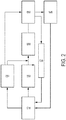
- FIG. 2 is a schematic of an exemplary cooling system 50.
- a water pump 52 pumps the coolant into an oil cooler 54.
- the coolant leaves the oil cooler and enters a cylinder block and head 56. While the coolant is in the engine block, it enters one or more of the passages, as described further below, and coolant is supplied to the cylinders of the internal combustion engine 10.
- the coolant exits the cylinder block and head 56 and enters the thermostat housing 58. If the coolant is above a threshold temperature the coolant that exits the thermostat housing 58 will be routed to a radiator 60 for cooling. If the coolant is below a threshold temperature the coolant that exits the thermostat housing 58 will be routed through a bypass circuit 62 back to the water pump.
- the water pump 52 may optionally pump the coolant into and after cooler 64 for an optional turbo (not shown).
- the coolant after exiting the after cooler 64 may mix with coolant leaving oil cooler prior to entering the cylinder block and head 56.
- the coolant after exiting the after cooler 64 may be directed to the thermostat housing 58.
- the internal combustion engine 10 includes a cylinder head 300 attached to an engine block 200.
- the engine block 200 includes a chamber that forms a liner bore 214.
- the liner bore 214 is lined with a cylinder liner 100.
- a liner bore 214 that is lined with a cylinder liner 100 may be referred to as a cylinder assembly or simply as a cylinder.
- the cylinder liner 100 includes an interior surface 120 that defines a cylinder bore 106 configured to house a piston 212 that, during operation of the internal combustion engine 10, moves within the cylinder bore 106 in a reciprocating fashion.
- a mixture of air and fuel is burned providing the power to drive the piston 212 away from the cylinder head 300.
- the cylinder head 300 includes at least one valve 302 that allows for one or more functions selected from intake of air into the combustion chamber 216, intake of fuel into the combustion chamber 216, and expulsion of exhaust gases from the combustion chamber 216.
- Suitable types of internal combustion engines include spark ignition engines or compression ignition engines (e.g., a diesel fuel engine or a dual fuel engine).
- the internal combustion engine 10 may include any number of cylinders. Each of the cylinders of the internal combustion engine 10 may individually have a single cylinder head 300. Alternatively, 2 or more cylinders may be associated with the cylinder head 300.
- the cylinder liner 100 When housed in the liner bore 214, the cylinder liner 100, in conjunction with the liner bore 214, forms a first annular coolant channel 250 and a second annular channel 252 below the first annular coolant channel 250 that allow for the passage of a coolant to cool the cylinder liner 100.
- the coolant is pumped within the internal combustion engine 10 through coolant passages and each of the first annular coolant channel 250 and a second annular coolant channel 252 may be fed from one or more coolant passages 254 (out of plane and shown in relief).
- the one or more coolant passages 254 may be configured to received coolant from the cylinder head 300.
- the one or more coolant passages 254 may receive coolant from the cylinder head water jacket (not shown). Suitable coolants include, but are not limited to, water, glycol, or a mixture thereof.
- FIG. 3 is a perspective view of an exemplary embodiment of the cylinder liner 100.
- the cylinder liner 100 has a hollow, generally cylindrical body that includes a top end 102 and a bottom end 104.
- Cylinder liner 100 includes cylinder bore 106 that spans longitudinally through the center of the cylinder liner 100, from the top end 102 to the bottom end 104. As indicated above, the cylinder bore 106 is defined by the interior surface 120.
- the cylinder liner 100 also includes an exterior surface 122 that is opposite and parallel to the interior surface 120.
- Located at the top end 102 is an annular flange 108 protruding radially outward from the exterior surface 122 of the cylinder liner 100.
- the annular flange 108 may be configured to rest in the recessed area 204 of the engine block 200.
- the engine block 200 includes a recessed area 204 that supports the annular flange 108 of the cylinder liner 100.
- the recessed area 204 allows the annular flange 108 of cylinder liner 100 to be situated lower than the surface of an engine block deck 220. Accordingly, the annular flange 108 of cylinder liner 100 is counter sunk into the engine block 200
- the cylinder liner 100 also includes an annular ridge 112 protruding radially outward from the cylindrical body of the cylinder liner 100.
- the annular ridge 112 may also be referred to as the pilot diameter.
- the annular ridge 112 separates the cylindrical body of cylinder liner 100 to form a first cylindrical section 114 and a second cylindrical section 116.
- the first cylindrical section 114 spans the length of the cylinder liner 100 between the annular flange 108 and the annular ridge 112.
- the first annular coolant channel 250 is formed to allow the passage of a coolant around the cylinder liner 100 at the first cylindrical section 114.
- the first cylindrical section 114 has a smooth surface. The smooth surface of the first cylindrical section 114 may transition to each of the annular flange 108 and annular ridge 112 via a radiused corner.
- a second annular coolant channel 252 is formed to allow the passage of a coolant around the cylinder liner 100 at the second cylindrical section 116.
- the second cylindrical section 116 has a smooth surface.
- the smooth surface of the second cylindrical section 116 may taper to meet the annular ridge 112.
- the cylinder liner 100 may be made from any suitable material or materials, such as for example, from an alloyed gray iron, aluminum, or steel (e.g., stainless steel).
- FIG. 4 is a partial cross section view of the cylinder liner 100 and the engine block 200 and best shows the interfaces where the annular ridge 112 and the annular flange 108 meet the liner bore 214 of the engine block 200.
- engine block 200 includes a recessed area 204. Situated at the bottom of recessed area 204 is a radially-extending, upward facing shoulder 206. Below the radially-extending, upward facing shoulder 206 in the liner bore 214 of engine block 200 is a liner bore ridge 218. Situated between the recessed area 204 and the liner bore ridge 218 is a liner bore groove 208.
- the liner bore groove 208 may have a continuous shape or non-continuous shape (e.g., it may vary in shape or size). Situated below the liner bore ridge 218 of the engine block 200 is an inner surface of the liner bore 210.
- the annular flange 108 of the cylinder liner 100 includes a lower face 110.
- the lower face 110 of the cylinder liner 100 engages the a radially-extending, upward facing shoulder 206 of the engine block 200.
- the annular ridge 112 of the cylinder liner 100 engages the liner bore ridge 218.
- the first annular coolant channel 250 is formed between the first cylindrical section 114 of the cylinder liner 100 and the cylinder bore groove 208. In certain embodiments, the first cylindrical section 114 and the cylinder bore groove 208 do not come into contact with each other within the first annular coolant channel 250.
- the radially-extending, upward facing shoulder 206 and the lower face 110 engage to form an interface that defines the top of the top of the first annular coolant channel 250.
- the lower face 110 of the cylinder liner 100 and the radially-extending, upward facing shoulder 206 of the engine block 200 are machined to form smooth surfaces. Accordingly, when coolant flows through the first annular coolant channel 250, coolant is retained within the first annular coolant channel 250 without the need for a secondary seal (e.g., sealing is provided only by the interfaces between the cylinder liner and the cylinder bore). This provides the ability for the first annular coolant channel 250 to be situated closer to the top end 102.
- the second annular coolant channel 252 is formed between the second cylindrical section 116 of the cylinder liner 100 and the inner surface of the liner bore 210.
- an interface is formed between the liner bore ridge 218 and the annular ridge 112 of the cylinder liner 100.
- the interface between the liner bore ridge 218 and the annular ridge 112 forms a seal and separates the first annular coolant channel 250 and second annular coolant channel 252.
- liner bore ridge 218 and the annular ridge 112 forms a seal, in certain conditions, for example during use in extremely cold temperatures, the seal may allow some cross talk of coolant between the first annular coolant channel 250 and the second annular coolant channel 252. In certain embodiments, an incomplete seal may be desired if cross talk of coolant between channels 250 and 252 is desired to prevent stagnation.
- the second annular coolant channel 252 may terminate at the bottom with an external seal (not shown).
- FIG. 5 is a diagram showing the flow of a coolant shown by arrows through the channels formed by the cylinder liner 100 and the engine block 200.
- the diagram in FIG. 5 is a relief of the flow path of the coolant.
- the coolant enters the one or more coolant passages 254 from one or more coolant flow passages in the internal combustion engine 10.
- the coolant exits the one or more coolant passages 254 and moves around the cylinder though the first annular coolant channel 250 and second annular coolant channel 252 to exit though the outlet 256.
- a similar coolant flowpath exists on the opposite side of the diagram where coolant similarly exits the one or more coolant passages 254 and moves around the cylinder though the first annular coolant channel 250 and second annular coolant channel 252 to exit though the outlet 256.
- the outlet 256 may communicate to allow the coolant to exit into a second cylinder (not shown), where it can assist in the cooling of one or more additional cylinders, or out of the engine block 200, where it can assist in the cooling of the cylinder head or be cooled and recycled back into the cylinder.
- FIG. 6 is a cross section view of the cylinder liner 100 housed in the engine block 200. Dashed lines have been be included in the FIG. 6 to describe the height and location of the first annular coolant channel 250 and the second annular coolant channel 252 in relation to the path of the piston between top dead center 350 and bottom dead center 358.
- the distance between top dead center 350 and bottom dead center 358 is shown with a bracketed line and may be referred to as the piston stroke 360.
- a bracketed line showing the distance between the top dead center 350 and the top of the first channel 352, which may be referred to as the distance to the first channel 366.
- the top of the first channel 352 is closer to the top end 102 of the cylinder liner 100 than top dead center 350.
- Dashed lines are shown for a top of the first channel (i.e., first channel top end) 352 and the bottom of the first channel (i.e., first channel bottom end) 354.
- a bracketed line is shown for a first channel height 362.
- dashed lines are shown for a top of the second channel (i.e., second channel top end) 356 and a bracketed line is shown for a second channel height 364.
- the bottom of the first channel 354 and the top of the second channel 356 flank the annular ridge 112.
- the top dead center 350 is closer to the top end 102 of the cylinder liner 100 than the annular ridge 112.
- the disclosed cylinder liner or cylinder liner and engine block assembly may be used in any application where it is desired to increase the reliability and operating life of the associated engine.
- the cylinder liner includes a first coolant channel and a second coolant channel. Due to the location of the first channel being in particularly close proximity to the top of the cylinder, the coolant can achieve better access to locations on the cylinder liner that are exposed to higher levels of heat from combustion.
- the second channel may provide cooling to the remaining portions of the cylinder liner. Accordingly, the disclosed cylinder liner allows for the management and removal of heat generated during combustion without the need for sacrificing the durability of the cylinder liner.
Landscapes
- Engineering & Computer Science (AREA)
- Chemical & Material Sciences (AREA)
- Combustion & Propulsion (AREA)
- Mechanical Engineering (AREA)
- General Engineering & Computer Science (AREA)
- Cylinder Crankcases Of Internal Combustion Engines (AREA)
Abstract
Description
- The present disclosure relates to an internal combustion engine, and more specifically to an internal combustion engine having dual-channel cylinder liner cooling.
- Internal combustion engines are typically liquid-cooled. A conventional coolant system for an internal combustion engine may include a coolant pump that pumps coolant into coolant passages of the engine. In certain internal combustion engines, replaceable cylinder liners define the cylinders and, in part, the combustion chambers of the engine.
- During combustion, an internal combustion engine may generate an immense amount of heat. In certain engines, a coolant passage is provided between and around the cylinder liners. Coolant may be directed through the coolant passage to cool the liners and carry heat energy away from the cylinders. Heat energy, however, is unevenly distributed in each cylinder liner since the top portion of each cylinder liner, where combustion takes place, experiences higher temperatures.
-
U.S. Patent No. 8,443,768 to Berghian et al. discloses an engine cylinder liner having a primary cooling gallery and a secondary cooling gallery about an upper portion of the cylinder liner. The secondary cooling gallery has an undulating configuration that is indicated to substantially increase contact surface of the coolant in the secondary cooling gallery. - In one aspect of the present disclosure, an internal combustion engine is provided including a cylinder head, a piston, and an engine block having a liner bore and a cylinder liner countersunk into the liner bore, wherein a first annular coolant channel having a channel top end and a channel bottom end is formed between the liner bore and the cylinder liner, the cylinder liner including a cylinder bore housing the piston, the piston slideably received within the cylinder bore for reciprocating between a top dead center position and a bottom dead center position, and a top end having an annular flange, wherein the channel top end is closer to the top end of the cylinder liner than the piston when at the top dead center position.
- In another aspect of the present disclosure, a cylinder liner is provided including, a cylinder bore capable of housing a piston, a top end having an annular flange, a first cylindrical section acting as a first coolant groove, a second cylindrical section acting as a second coolant groove, and an annular ridge that separates the first cylindrical section and the second cylindrical section.
- In another aspect of the present disclosure, a cooling system is provided including a coolant in fluid communication with a water pump, an oil cooler, a thermostat housing, a radiator, and an engine block and cylinder head assembly including a cylinder head, a piston, and an engine block having a liner bore and a cylinder liner countersunk into the liner bore, wherein a first annular channel having an annular channel top end and an annular channel bottom end is formed between the liner bore and the cylinder liner, the first annular channel; the cylinder liner including a cylinder bore housing the piston, the piston is capable of a piston stroke that includes a top dead center, a top end having an annular flange, a first cylindrical section, a second cylindrical section, and an annular ridge that separates the first cylindrical section and the second cylindrical section; wherein the annular channel top end is closer to the top end of the cylinder liner than the top dead center of the piston.
- Other features and aspects of this disclosure will be apparent from the following description and the accompanying drawings.
- Further features and advantages of the invention will become apparent from the description of embodiments using the accompanying drawings. In the drawings:
-
FIG. 1 is a partial cross section of a portion of an internal combustion engine including an exemplary cylinder liner housed in a liner bore of an engine block; -
FIG. 2 is a schematic of an embodiment of an exemplary engine cooling system -
FIG. 3 is a perspective view of an embodiment of an exemplary cylinder liner; -
FIG. 4 is a partial cross section view of the cylinder liner and the engine block ofFIG. 1 ; -
FIG. 5 is a diagram showing the flow of a coolant through the channels formed by the cylinder liner; and -
FIG. 6 is a cross section view of the cylinder liner and the engine block ofFIG. 1 . - Referring to the drawings,
FIG. 1 is a partial cross section of a portion of aninternal combustion engine 10 such as a diesel engine. Theinternal combustion engine 10 may provide power to various types of applications and/or machines. For example, theinternal combustion engine 10 may power a machine such as an off-highway truck, a railway locomotive, an earth-moving machine, such as a wheel loader, excavator, dump truck, backhoe, motor grader, material handler, or the like. The term "machine" can also refer to stationary equipment like a generator that is driven by theinternal combustion engine 10 to generate electricity -
FIG. 2 is a schematic of an exemplary cooling system 50. In the cooling system 50, awater pump 52 pumps the coolant into anoil cooler 54. The coolant leaves the oil cooler and enters a cylinder block andhead 56. While the coolant is in the engine block, it enters one or more of the passages, as described further below, and coolant is supplied to the cylinders of theinternal combustion engine 10. The coolant exits the cylinder block andhead 56 and enters thethermostat housing 58. If the coolant is above a threshold temperature the coolant that exits thethermostat housing 58 will be routed to aradiator 60 for cooling. If the coolant is below a threshold temperature the coolant that exits thethermostat housing 58 will be routed through abypass circuit 62 back to the water pump. Thewater pump 52 may optionally pump the coolant into and aftercooler 64 for an optional turbo (not shown). In certain embodiments, the coolant after exiting the aftercooler 64 may mix with coolant leaving oil cooler prior to entering the cylinder block andhead 56. In other embodiments, the coolant after exiting the aftercooler 64 may be directed to thethermostat housing 58. - Returning to
FIG. 1 , theinternal combustion engine 10 includes acylinder head 300 attached to anengine block 200. Theengine block 200 includes a chamber that forms a liner bore 214. Theliner bore 214 is lined with acylinder liner 100. As used herein, a liner bore 214 that is lined with acylinder liner 100 may be referred to as a cylinder assembly or simply as a cylinder. Thecylinder liner 100 includes aninterior surface 120 that defines acylinder bore 106 configured to house apiston 212 that, during operation of theinternal combustion engine 10, moves within thecylinder bore 106 in a reciprocating fashion. The area defined by thecylinder bore 106 of thecylinder liner 100, thecylinder head 300, and thepiston 212 forms acombustion chamber 216. In thecombustion chamber 216, a mixture of air and fuel is burned providing the power to drive thepiston 212 away from thecylinder head 300. Thecylinder head 300 includes at least onevalve 302 that allows for one or more functions selected from intake of air into thecombustion chamber 216, intake of fuel into thecombustion chamber 216, and expulsion of exhaust gases from thecombustion chamber 216. Suitable types of internal combustion engines include spark ignition engines or compression ignition engines (e.g., a diesel fuel engine or a dual fuel engine). Theinternal combustion engine 10 may include any number of cylinders. Each of the cylinders of theinternal combustion engine 10 may individually have asingle cylinder head 300. Alternatively, 2 or more cylinders may be associated with thecylinder head 300. - When housed in the liner bore 214, the
cylinder liner 100, in conjunction with the liner bore 214, forms a firstannular coolant channel 250 and a secondannular channel 252 below the firstannular coolant channel 250 that allow for the passage of a coolant to cool thecylinder liner 100. The coolant is pumped within theinternal combustion engine 10 through coolant passages and each of the firstannular coolant channel 250 and a secondannular coolant channel 252 may be fed from one or more coolant passages 254 (out of plane and shown in relief). The one or morecoolant passages 254 may be configured to received coolant from thecylinder head 300. For example, the one or morecoolant passages 254 may receive coolant from the cylinder head water jacket (not shown). Suitable coolants include, but are not limited to, water, glycol, or a mixture thereof. -
FIG. 3 is a perspective view of an exemplary embodiment of thecylinder liner 100. Thecylinder liner 100 has a hollow, generally cylindrical body that includes atop end 102 and abottom end 104.Cylinder liner 100 includescylinder bore 106 that spans longitudinally through the center of thecylinder liner 100, from thetop end 102 to thebottom end 104. As indicated above, thecylinder bore 106 is defined by theinterior surface 120. Thecylinder liner 100 also includes an exterior surface 122 that is opposite and parallel to theinterior surface 120. Located at thetop end 102 is anannular flange 108 protruding radially outward from the exterior surface 122 of thecylinder liner 100. Theannular flange 108 may be configured to rest in therecessed area 204 of theengine block 200. As shown inFIG. 1 , theengine block 200 includes a recessedarea 204 that supports theannular flange 108 of thecylinder liner 100. The recessedarea 204 allows theannular flange 108 ofcylinder liner 100 to be situated lower than the surface of anengine block deck 220. Accordingly, theannular flange 108 ofcylinder liner 100 is counter sunk into theengine block 200 - The
cylinder liner 100 also includes anannular ridge 112 protruding radially outward from the cylindrical body of thecylinder liner 100. Theannular ridge 112 may also be referred to as the pilot diameter. Theannular ridge 112 separates the cylindrical body ofcylinder liner 100 to form a firstcylindrical section 114 and a secondcylindrical section 116. The firstcylindrical section 114 spans the length of thecylinder liner 100 between theannular flange 108 and theannular ridge 112. When thecylinder liner 100 is housed in the liner bore 214 of theengine block 200, the firstannular coolant channel 250 is formed to allow the passage of a coolant around thecylinder liner 100 at the firstcylindrical section 114. The firstcylindrical section 114 has a smooth surface. The smooth surface of the firstcylindrical section 114 may transition to each of theannular flange 108 andannular ridge 112 via a radiused corner. - Similar to the first
cylindrical section 114, when thecylinder liner 100 is housed in the liner bore 214 of theengine block 200, a secondannular coolant channel 252 is formed to allow the passage of a coolant around thecylinder liner 100 at the secondcylindrical section 116. The secondcylindrical section 116 has a smooth surface. The smooth surface of the secondcylindrical section 116 may taper to meet theannular ridge 112. Thecylinder liner 100 may be made from any suitable material or materials, such as for example, from an alloyed gray iron, aluminum, or steel (e.g., stainless steel). -
FIG. 4 is a partial cross section view of thecylinder liner 100 and theengine block 200 and best shows the interfaces where theannular ridge 112 and theannular flange 108 meet the liner bore 214 of theengine block 200. As indicated above,engine block 200 includes a recessedarea 204. Situated at the bottom of recessedarea 204 is a radially-extending, upward facingshoulder 206. Below the radially-extending, upward facingshoulder 206 in the liner bore 214 ofengine block 200 is aliner bore ridge 218. Situated between the recessedarea 204 and the liner boreridge 218 is aliner bore groove 208. The liner boregroove 208 may have a continuous shape or non-continuous shape (e.g., it may vary in shape or size). Situated below the liner boreridge 218 of theengine block 200 is an inner surface of the liner bore 210. - The
annular flange 108 of thecylinder liner 100 includes alower face 110. When thecylinder liner 100 is inserted into the liner bore 214, thelower face 110 of thecylinder liner 100 engages the a radially-extending, upward facingshoulder 206 of theengine block 200. Further, theannular ridge 112 of thecylinder liner 100 engages the liner boreridge 218. The firstannular coolant channel 250 is formed between the firstcylindrical section 114 of thecylinder liner 100 and the cylinder boregroove 208. In certain embodiments, the firstcylindrical section 114 and the cylinder boregroove 208 do not come into contact with each other within the firstannular coolant channel 250. The radially-extending, upward facingshoulder 206 and thelower face 110 engage to form an interface that defines the top of the top of the firstannular coolant channel 250. Thelower face 110 of thecylinder liner 100 and the radially-extending, upward facingshoulder 206 of theengine block 200 are machined to form smooth surfaces. Accordingly, when coolant flows through the firstannular coolant channel 250, coolant is retained within the firstannular coolant channel 250 without the need for a secondary seal (e.g., sealing is provided only by the interfaces between the cylinder liner and the cylinder bore). This provides the ability for the firstannular coolant channel 250 to be situated closer to thetop end 102. - The second
annular coolant channel 252 is formed between the secondcylindrical section 116 of thecylinder liner 100 and the inner surface of the liner bore 210. When thecylinder liner 100 is inserted into the liner bore 214, an interface is formed between the liner boreridge 218 and theannular ridge 112 of thecylinder liner 100. The interface between the liner boreridge 218 and theannular ridge 112 forms a seal and separates the firstannular coolant channel 250 and secondannular coolant channel 252. While liner boreridge 218 and theannular ridge 112 forms a seal, in certain conditions, for example during use in extremely cold temperatures, the seal may allow some cross talk of coolant between the firstannular coolant channel 250 and the secondannular coolant channel 252. In certain embodiments, an incomplete seal may be desired if cross talk of coolant betweenchannels annular coolant channel 252 may terminate at the bottom with an external seal (not shown). -
FIG. 5 is a diagram showing the flow of a coolant shown by arrows through the channels formed by thecylinder liner 100 and theengine block 200. The diagram inFIG. 5 is a relief of the flow path of the coolant. The coolant enters the one ormore coolant passages 254 from one or more coolant flow passages in theinternal combustion engine 10. The coolant exits the one ormore coolant passages 254 and moves around the cylinder though the firstannular coolant channel 250 and secondannular coolant channel 252 to exit though theoutlet 256. A similar coolant flowpath exists on the opposite side of the diagram where coolant similarly exits the one ormore coolant passages 254 and moves around the cylinder though the firstannular coolant channel 250 and secondannular coolant channel 252 to exit though theoutlet 256. Theoutlet 256 may communicate to allow the coolant to exit into a second cylinder (not shown), where it can assist in the cooling of one or more additional cylinders, or out of theengine block 200, where it can assist in the cooling of the cylinder head or be cooled and recycled back into the cylinder. -
FIG. 6 is a cross section view of thecylinder liner 100 housed in theengine block 200. Dashed lines have been be included in theFIG. 6 to describe the height and location of the firstannular coolant channel 250 and the secondannular coolant channel 252 in relation to the path of the piston between topdead center 350 and bottomdead center 358. The distance between topdead center 350 and bottomdead center 358 is shown with a bracketed line and may be referred to as thepiston stroke 360. Also shown is a bracketed line showing the distance between the topdead center 350 and the top of thefirst channel 352, which may be referred to as the distance to thefirst channel 366. The top of thefirst channel 352 is closer to thetop end 102 of thecylinder liner 100 than topdead center 350. Dashed lines are shown for a top of the first channel (i.e., first channel top end) 352 and the bottom of the first channel (i.e., first channel bottom end) 354. A bracketed line is shown for afirst channel height 362. Similarly, dashed lines are shown for a top of the second channel (i.e., second channel top end) 356 and a bracketed line is shown for asecond channel height 364. The bottom of thefirst channel 354 and the top of thesecond channel 356 flank theannular ridge 112. The topdead center 350 is closer to thetop end 102 of thecylinder liner 100 than theannular ridge 112. - The disclosed cylinder liner or cylinder liner and engine block assembly may be used in any application where it is desired to increase the reliability and operating life of the associated engine. In the disclosed embodiment, the cylinder liner includes a first coolant channel and a second coolant channel. Due to the location of the first channel being in particularly close proximity to the top of the cylinder, the coolant can achieve better access to locations on the cylinder liner that are exposed to higher levels of heat from combustion. The second channel may provide cooling to the remaining portions of the cylinder liner. Accordingly, the disclosed cylinder liner allows for the management and removal of heat generated during combustion without the need for sacrificing the durability of the cylinder liner.
- It will be appreciated that the foregoing description provides examples of the disclosed system and technique. However, it is contemplated that other implementations of the disclosure may differ in detail from the foregoing examples. All references to the disclosure or examples thereof, are intended to reference the particular examples being discussed at that point and are not intended to imply any limitation as to the scope of the disclosure more generally. All language of distinction and disparagement with respect to certain features is intended to indicate a lack of preference for those features, but not to exclude such from the scope of the disclosure entirely unless otherwise indicated.
Claims (10)
- An internal combustion engine (10), comprising:a cylinder head (300);a piston (212); andan engine block (200) having a liner bore (210) and a cylinder liner (100) countersunk into the liner bore (210), wherein a first annular coolant channel (250) having a channel top end (352) and a channel bottom end (354) is formed between the liner bore (210) and the cylinder liner (100), the cylinder liner (100) comprising:a cylinder bore (106) housing the piston (212), the piston (212) slideably received within the cylinder bore (106) for reciprocating between a top dead center position and a bottom dead center position, anda top end (102) having an annular flange (108),wherein the channel top end (352) is closer to the top end (102) of the cylinder liner (100) than the piston (212) when at a top dead center position.
- The internal combustion engine (10) of claim 1, wherein the channel top end (352) is above the top dead center position of the piston (212).
- The internal combustion engine of claim 1 or 2, wherein the cylinder liner (100) and the liner bore (210) form a second annular coolant channel (252) below the first annular coolant channel (250).
- The internal combustion engine (10) of claim 3, wherein the engine block (200) includes a coolant passage (254) that is configured to accept coolant from the cylinder head (300) and feed the coolant into the first annular coolant channel (250) and the second annular coolant channel (252).
- The internal combustion engine (10) of any one of claims 1-4, wherein the liner bore (210) includes a recessed area (204) with an upward facing shoulder (206) and the annular flange (108) of the cylinder liner (100) forms a sealing interface with the upward facing shoulder (206) capable of retaining coolant in the first annular coolant channel (250).
- The internal combustion engine (10) of claim 5, wherein there is no secondary seal between the cylinder liner (100) and liner bore (210) above the channel top end (352).
- The internal combustion engine (10) of any one of claims 1-6, wherein the liner bore (210) includes a liner bore ridge (218) and the annular ridge (112) of the cylinder liner (100) forms an interface with the liner bore ridge (218).
- The internal combustion engine (10) of claim 7, wherein the cylinder liner (100) forms a second annular channel (252) and the first annular channel (250) and the second annular channel (252) are separated by the interface between the liner bore ridge (218) and the annular ridge (112) of the cylinder liner (100).
- The internal combustion engine (10) of claim 7 or 8, wherein the top dead center position of the piston (212) is closer to the top end (102) of the cylinder liner (100) than the annular ridge (112) of the cylinder liner (100).
- The internal combustion engine (10) of claim 9, wherein the top dead center position of the piston (212) is above the annular ridge (112) of the cylinder liner (100).
Applications Claiming Priority (1)
| Application Number | Priority Date | Filing Date | Title |
|---|---|---|---|
| US16/790,838 US11549459B2 (en) | 2020-02-14 | 2020-02-14 | Internal combustion engine with dual-channel cylinder liner cooling |
Publications (2)
| Publication Number | Publication Date |
|---|---|
| EP3865699A1 true EP3865699A1 (en) | 2021-08-18 |
| EP3865699B1 EP3865699B1 (en) | 2026-04-22 |
Family
ID=74346881
Family Applications (1)
| Application Number | Title | Priority Date | Filing Date |
|---|---|---|---|
| EP21153882.2A Active EP3865699B1 (en) | 2020-02-14 | 2021-01-27 | Internal combustion engine with dual-channel cylinder liner cooling |
Country Status (3)
| Country | Link |
|---|---|
| US (1) | US11549459B2 (en) |
| EP (1) | EP3865699B1 (en) |
| CN (1) | CN113266490B (en) |
Families Citing this family (3)
| Publication number | Priority date | Publication date | Assignee | Title |
|---|---|---|---|---|
| USD980285S1 (en) * | 2020-09-30 | 2023-03-07 | Caterpillar Inc. | Liner for an engine block |
| USD980869S1 (en) * | 2020-09-30 | 2023-03-14 | Caterpillar Inc. | Liner for an engine block |
| CN115163324B (en) * | 2022-08-29 | 2024-04-16 | 潍柴动力股份有限公司 | Cylinder assembly and internal combustion engine |
Citations (6)
| Publication number | Priority date | Publication date | Assignee | Title |
|---|---|---|---|---|
| DE3417515C1 (en) * | 1984-05-11 | 1985-08-14 | Krupp Mak Maschinenbau Gmbh, 2300 Kiel | Internal combustion engine with piston liners |
| US5970941A (en) * | 1998-06-16 | 1999-10-26 | Caterpillar Inc. | Cylinder liner connecting arrangement and method |
| US20060219192A1 (en) * | 2005-03-31 | 2006-10-05 | Ipd Corporation | Cylinder liner |
| DE102011116587A1 (en) * | 2011-10-21 | 2013-04-25 | Audi Ag | Liquid-cooled internal combustion engine for vehicle, has cooling jacket with independently controlled cooling efficiency of upper area and lower area of cylinder wall, where intermediate area is recessed from cooling jacket |
| US8443768B2 (en) | 2009-02-17 | 2013-05-21 | Mahle International Gmbh | High-flow cylinder liner cooling gallery |
| CN112196688A (en) * | 2020-09-21 | 2021-01-08 | 东风商用车有限公司 | Water jacket structure of engine |
Family Cites Families (25)
| Publication number | Priority date | Publication date | Assignee | Title |
|---|---|---|---|---|
| DE1476350A1 (en) * | 1965-07-31 | 1969-07-31 | Daimler Benz Ag | Piston internal combustion engine with a cooling water circuit generated by a water pump |
| US4244330A (en) * | 1978-11-13 | 1981-01-13 | Cummins Engine Company, Inc. | Engine cylinder liner having a mid stop |
| US5386805A (en) * | 1991-06-06 | 1995-02-07 | Toyota Jidosha Kabushiki Kaisha | Cooling system of an internal combustion engine |
| JP2780518B2 (en) * | 1991-06-10 | 1998-07-30 | トヨタ自動車株式会社 | Internal combustion engine cooling system |
| US5150668A (en) * | 1992-02-20 | 1992-09-29 | Caterpillar, Inc. | Cylinder liner with coolant sleeve |
| US5299538A (en) * | 1992-06-26 | 1994-04-05 | Detroit Diesel Corporation | Internal combustion engine block having a cylinder liner shunt flow cooling system and method of cooling same |
| SE508983C2 (en) * | 1992-12-30 | 1998-11-23 | Scania Cv Ab | Wet cylinder lining |
| US5505167A (en) * | 1993-05-05 | 1996-04-09 | Detroit Diesel Corporation | Internal combustion engine block having a cylinder liner shunt flow cooling system and method of cooling same |
| US5979374A (en) * | 1998-06-12 | 1999-11-09 | Cummins Engine Company, Inc. | Control cooled cylinder liner |
| US6123052A (en) * | 1998-08-27 | 2000-09-26 | Jahn; George | Waffle cast iron cylinder liner |
| US6145481A (en) * | 1999-07-07 | 2000-11-14 | Caterpillar Inc. | Cooling ring for a cylinder liner in an internal combustion engine |
| EP1679434A4 (en) * | 2003-10-16 | 2009-04-29 | Riken Kk | INTERNAL COMBUSTION ENGINE AND SHOE INSTALLATION RING |
| US7162798B2 (en) * | 2004-02-26 | 2007-01-16 | Electro-Motive Diesel, Inc. | Ported engine cylinder liner with selectively laser-hardened and induction-hardened bore |
| JP4395002B2 (en) | 2004-04-27 | 2010-01-06 | トヨタ自動車株式会社 | Cylinder block cooling structure |
| DE102005048566A1 (en) * | 2005-10-11 | 2007-04-12 | Man Nutzfahrzeuge Ag | Auto-ignition internal combustion engine with combustion chambers for high ignition pressures |
| US7131417B1 (en) * | 2005-10-20 | 2006-11-07 | Alfred J. Buescher | Cylinder liner providing coolant shunt flow |
| US7337756B1 (en) * | 2006-08-10 | 2008-03-04 | Pai Industries, Inc. | Cylinder liner for internal combustion engine |
| DE102009059057A1 (en) * | 2009-12-18 | 2011-06-22 | MAHLE International GmbH, 70376 | Assembly of cylinder liner and crankcase |
| US20120304954A1 (en) * | 2011-06-02 | 2012-12-06 | Caterpillar Inc. | Cylinder liner with a case on a cuff-ring groove |
| DE102011085476A1 (en) * | 2011-10-28 | 2013-05-02 | Ks Kolbenschmidt Gmbh | Functionally optimized design of a cylinder liner |
| EP3117089B1 (en) * | 2014-03-14 | 2022-05-04 | New Power Concepts LLC | Linear cross-head bearing for stirling engine |
| US9593639B2 (en) * | 2014-08-19 | 2017-03-14 | Caterpillar Inc. | Cylinder liner having annular coolant circulation groove |
| US9624869B2 (en) * | 2014-08-20 | 2017-04-18 | Caterpillar Inc. | Cooling moat for upper cylinder liner seal |
| US10107228B2 (en) * | 2015-03-31 | 2018-10-23 | Cummins Inc. | Internal combustion engine cylinder liner flange with non-circular profile |
| CN104948289B (en) * | 2015-06-29 | 2018-04-20 | 重庆建设机电有限责任公司 | The totally-enclosed interior recirculated water cooling structure of cooling engine for motor cycle water |
-
2020
- 2020-02-14 US US16/790,838 patent/US11549459B2/en active Active
-
2021
- 2021-01-27 EP EP21153882.2A patent/EP3865699B1/en active Active
- 2021-02-07 CN CN202110167998.4A patent/CN113266490B/en active Active
Patent Citations (6)
| Publication number | Priority date | Publication date | Assignee | Title |
|---|---|---|---|---|
| DE3417515C1 (en) * | 1984-05-11 | 1985-08-14 | Krupp Mak Maschinenbau Gmbh, 2300 Kiel | Internal combustion engine with piston liners |
| US5970941A (en) * | 1998-06-16 | 1999-10-26 | Caterpillar Inc. | Cylinder liner connecting arrangement and method |
| US20060219192A1 (en) * | 2005-03-31 | 2006-10-05 | Ipd Corporation | Cylinder liner |
| US8443768B2 (en) | 2009-02-17 | 2013-05-21 | Mahle International Gmbh | High-flow cylinder liner cooling gallery |
| DE102011116587A1 (en) * | 2011-10-21 | 2013-04-25 | Audi Ag | Liquid-cooled internal combustion engine for vehicle, has cooling jacket with independently controlled cooling efficiency of upper area and lower area of cylinder wall, where intermediate area is recessed from cooling jacket |
| CN112196688A (en) * | 2020-09-21 | 2021-01-08 | 东风商用车有限公司 | Water jacket structure of engine |
Also Published As
| Publication number | Publication date |
|---|---|
| US11549459B2 (en) | 2023-01-10 |
| CN113266490A (en) | 2021-08-17 |
| CN113266490B (en) | 2025-07-29 |
| US20210254578A1 (en) | 2021-08-19 |
| EP3865699B1 (en) | 2026-04-22 |
Similar Documents
| Publication | Publication Date | Title |
|---|---|---|
| EP3865699B1 (en) | Internal combustion engine with dual-channel cylinder liner cooling | |
| US9127617B2 (en) | Internal combustion engine having improved cooling arrangement | |
| US4638769A (en) | Engine having a multipiece cylinder block | |
| US4911109A (en) | Cooling system for heat insulating engine | |
| CN106194382B (en) | Internal combustion engine and coolant pump | |
| GB2327462A (en) | A replaceable cylinder liner for an internal combustion engine | |
| CN107917013B (en) | Piston assembly with improved lubricity | |
| CN114233507B (en) | Cooling water jacket of engine cylinder cover | |
| US4941436A (en) | Cooling system for I.C.E. valve seat inserts | |
| US6363894B1 (en) | Diesel engine having a cylinder liner with improved cooling characteristics | |
| KR100319179B1 (en) | Internal combustion engine block with cylinder liner decentralized flow cooling system and its cooling method | |
| US20030029396A1 (en) | Oil injection system | |
| JP2017110619A (en) | Multi-cylinder engine cooling structure | |
| US5453573A (en) | Engine cooling system | |
| JPS59185818A (en) | Cylinder liner cooling system of water-cooled engine | |
| US11371465B2 (en) | Cylinder head and engine | |
| US11525419B1 (en) | Engine power module and cylinder head for same | |
| US20150285126A1 (en) | Oil channel for engine | |
| CN223120037U (en) | Cylinder components and internal combustion engines | |
| EP3865687B1 (en) | Internal combustion engine with top-down cooling | |
| JP3142149B2 (en) | Oil-cooled multi-cylinder engine | |
| CN214533255U (en) | Cylinder head and engine | |
| JP3820110B2 (en) | Cylinder liner cooling structure | |
| JP2023117543A (en) | engine | |
| JP2005194884A (en) | Engine cooling system |
Legal Events
| Date | Code | Title | Description |
|---|---|---|---|
| PUAI | Public reference made under article 153(3) epc to a published international application that has entered the european phase |
Free format text: ORIGINAL CODE: 0009012 |
|
| STAA | Information on the status of an ep patent application or granted ep patent |
Free format text: STATUS: THE APPLICATION HAS BEEN PUBLISHED |
|
| AK | Designated contracting states |
Kind code of ref document: A1 Designated state(s): AL AT BE BG CH CY CZ DE DK EE ES FI FR GB GR HR HU IE IS IT LI LT LU LV MC MK MT NL NO PL PT RO RS SE SI SK SM TR |
|
| STAA | Information on the status of an ep patent application or granted ep patent |
Free format text: STATUS: REQUEST FOR EXAMINATION WAS MADE |
|
| 17P | Request for examination filed |
Effective date: 20220210 |
|
| RBV | Designated contracting states (corrected) |
Designated state(s): AL AT BE BG CH CY CZ DE DK EE ES FI FR GB GR HR HU IE IS IT LI LT LU LV MC MK MT NL NO PL PT RO RS SE SI SK SM TR |
|
| STAA | Information on the status of an ep patent application or granted ep patent |
Free format text: STATUS: EXAMINATION IS IN PROGRESS |
|
| 17Q | First examination report despatched |
Effective date: 20231208 |
|
| GRAP | Despatch of communication of intention to grant a patent |
Free format text: ORIGINAL CODE: EPIDOSNIGR1 |
|
| STAA | Information on the status of an ep patent application or granted ep patent |
Free format text: STATUS: GRANT OF PATENT IS INTENDED |
|
| INTG | Intention to grant announced |
Effective date: 20251124 |
|
| GRAS | Grant fee paid |
Free format text: ORIGINAL CODE: EPIDOSNIGR3 |
|
| GRAA | (expected) grant |
Free format text: ORIGINAL CODE: 0009210 |
|
| STAA | Information on the status of an ep patent application or granted ep patent |
Free format text: STATUS: THE PATENT HAS BEEN GRANTED |
|
| P01 | Opt-out of the competence of the unified patent court (upc) registered |
Free format text: CASE NUMBER: UPC_APP_0008161_3865699/2026 Effective date: 20260226 |
|
| AK | Designated contracting states |
Kind code of ref document: B1 Designated state(s): AL AT BE BG CH CY CZ DE DK EE ES FI FR GB GR HR HU IE IS IT LI LT LU LV MC MK MT NL NO PL PT RO RS SE SI SK SM TR |
|
| REG | Reference to a national code |
Ref country code: CH Ref legal event code: F10 Free format text: ST27 STATUS EVENT CODE: U-0-0-F10-F00 (AS PROVIDED BY THE NATIONAL OFFICE) Effective date: 20260422 Ref country code: GB Ref legal event code: FG4D |