EP3865692A1 - Engine and secondary power unit integrated operation - Google Patents
Engine and secondary power unit integrated operation Download PDFInfo
- Publication number
- EP3865692A1 EP3865692A1 EP21157222.7A EP21157222A EP3865692A1 EP 3865692 A1 EP3865692 A1 EP 3865692A1 EP 21157222 A EP21157222 A EP 21157222A EP 3865692 A1 EP3865692 A1 EP 3865692A1
- Authority
- EP
- European Patent Office
- Prior art keywords
- compressor
- power unit
- secondary power
- turbine
- engine
- Prior art date
- Legal status (The legal status is an assumption and is not a legal conclusion. Google has not performed a legal analysis and makes no representation as to the accuracy of the status listed.)
- Granted
Links
Images



Classifications
-
- F—MECHANICAL ENGINEERING; LIGHTING; HEATING; WEAPONS; BLASTING
- F02—COMBUSTION ENGINES; HOT-GAS OR COMBUSTION-PRODUCT ENGINE PLANTS
- F02C—GAS-TURBINE PLANTS; AIR INTAKES FOR JET-PROPULSION PLANTS; CONTROLLING FUEL SUPPLY IN AIR-BREATHING JET-PROPULSION PLANTS
- F02C7/00—Features, components parts, details or accessories, not provided for in, or of interest apart form groups F02C1/00 - F02C6/00; Air intakes for jet-propulsion plants
- F02C7/32—Arrangement, mounting, or driving, of auxiliaries
-
- F—MECHANICAL ENGINEERING; LIGHTING; HEATING; WEAPONS; BLASTING
- F02—COMBUSTION ENGINES; HOT-GAS OR COMBUSTION-PRODUCT ENGINE PLANTS
- F02C—GAS-TURBINE PLANTS; AIR INTAKES FOR JET-PROPULSION PLANTS; CONTROLLING FUEL SUPPLY IN AIR-BREATHING JET-PROPULSION PLANTS
- F02C3/00—Gas-turbine plants characterised by the use of combustion products as the working fluid
- F02C3/04—Gas-turbine plants characterised by the use of combustion products as the working fluid having a turbine driving a compressor
-
- B—PERFORMING OPERATIONS; TRANSPORTING
- B64—AIRCRAFT; AVIATION; COSMONAUTICS
- B64D—EQUIPMENT FOR FITTING IN OR TO AIRCRAFT; FLIGHT SUITS; PARACHUTES; ARRANGEMENT OR MOUNTING OF POWER PLANTS OR PROPULSION TRANSMISSIONS IN AIRCRAFT
- B64D13/00—Arrangements or adaptations of air-treatment apparatus for aircraft crew or passengers, or freight space
- B64D13/06—Arrangements or adaptations of air-treatment apparatus for aircraft crew or passengers, or freight space the air being conditioned
-
- B—PERFORMING OPERATIONS; TRANSPORTING
- B64—AIRCRAFT; AVIATION; COSMONAUTICS
- B64D—EQUIPMENT FOR FITTING IN OR TO AIRCRAFT; FLIGHT SUITS; PARACHUTES; ARRANGEMENT OR MOUNTING OF POWER PLANTS OR PROPULSION TRANSMISSIONS IN AIRCRAFT
- B64D41/00—Power installations for auxiliary purposes
-
- F—MECHANICAL ENGINEERING; LIGHTING; HEATING; WEAPONS; BLASTING
- F02—COMBUSTION ENGINES; HOT-GAS OR COMBUSTION-PRODUCT ENGINE PLANTS
- F02C—GAS-TURBINE PLANTS; AIR INTAKES FOR JET-PROPULSION PLANTS; CONTROLLING FUEL SUPPLY IN AIR-BREATHING JET-PROPULSION PLANTS
- F02C6/00—Plural gas-turbine plants; Combinations of gas-turbine plants with other apparatus; Adaptations of gas-turbine plants for special use
- F02C6/04—Gas-turbine plants providing heated or pressurised working fluid for other apparatus, e.g. without mechanical power output
- F02C6/06—Gas-turbine plants providing heated or pressurised working fluid for other apparatus, e.g. without mechanical power output providing compressed gas
- F02C6/08—Gas-turbine plants providing heated or pressurised working fluid for other apparatus, e.g. without mechanical power output providing compressed gas the gas being bled from the gas-turbine compressor
-
- F—MECHANICAL ENGINEERING; LIGHTING; HEATING; WEAPONS; BLASTING
- F02—COMBUSTION ENGINES; HOT-GAS OR COMBUSTION-PRODUCT ENGINE PLANTS
- F02C—GAS-TURBINE PLANTS; AIR INTAKES FOR JET-PROPULSION PLANTS; CONTROLLING FUEL SUPPLY IN AIR-BREATHING JET-PROPULSION PLANTS
- F02C7/00—Features, components parts, details or accessories, not provided for in, or of interest apart form groups F02C1/00 - F02C6/00; Air intakes for jet-propulsion plants
- F02C7/26—Starting; Ignition
- F02C7/268—Starting drives for the rotor, acting directly on the rotor of the gas turbine to be started
- F02C7/275—Mechanical drives
-
- F—MECHANICAL ENGINEERING; LIGHTING; HEATING; WEAPONS; BLASTING
- F02—COMBUSTION ENGINES; HOT-GAS OR COMBUSTION-PRODUCT ENGINE PLANTS
- F02C—GAS-TURBINE PLANTS; AIR INTAKES FOR JET-PROPULSION PLANTS; CONTROLLING FUEL SUPPLY IN AIR-BREATHING JET-PROPULSION PLANTS
- F02C7/00—Features, components parts, details or accessories, not provided for in, or of interest apart form groups F02C1/00 - F02C6/00; Air intakes for jet-propulsion plants
- F02C7/36—Power transmission arrangements between the different shafts of the gas turbine plant, or between the gas-turbine plant and the power user
-
- B—PERFORMING OPERATIONS; TRANSPORTING
- B64—AIRCRAFT; AVIATION; COSMONAUTICS
- B64D—EQUIPMENT FOR FITTING IN OR TO AIRCRAFT; FLIGHT SUITS; PARACHUTES; ARRANGEMENT OR MOUNTING OF POWER PLANTS OR PROPULSION TRANSMISSIONS IN AIRCRAFT
- B64D13/00—Arrangements or adaptations of air-treatment apparatus for aircraft crew or passengers, or freight space
- B64D13/06—Arrangements or adaptations of air-treatment apparatus for aircraft crew or passengers, or freight space the air being conditioned
- B64D2013/0603—Environmental Control Systems
- B64D2013/0611—Environmental Control Systems combined with auxiliary power units (APU's)
-
- B—PERFORMING OPERATIONS; TRANSPORTING
- B64—AIRCRAFT; AVIATION; COSMONAUTICS
- B64D—EQUIPMENT FOR FITTING IN OR TO AIRCRAFT; FLIGHT SUITS; PARACHUTES; ARRANGEMENT OR MOUNTING OF POWER PLANTS OR PROPULSION TRANSMISSIONS IN AIRCRAFT
- B64D13/00—Arrangements or adaptations of air-treatment apparatus for aircraft crew or passengers, or freight space
- B64D13/06—Arrangements or adaptations of air-treatment apparatus for aircraft crew or passengers, or freight space the air being conditioned
- B64D2013/0603—Environmental Control Systems
- B64D2013/0648—Environmental Control Systems with energy recovery means, e.g. using turbines
-
- F—MECHANICAL ENGINEERING; LIGHTING; HEATING; WEAPONS; BLASTING
- F02—COMBUSTION ENGINES; HOT-GAS OR COMBUSTION-PRODUCT ENGINE PLANTS
- F02C—GAS-TURBINE PLANTS; AIR INTAKES FOR JET-PROPULSION PLANTS; CONTROLLING FUEL SUPPLY IN AIR-BREATHING JET-PROPULSION PLANTS
- F02C6/00—Plural gas-turbine plants; Combinations of gas-turbine plants with other apparatus; Adaptations of gas-turbine plants for special use
- F02C6/18—Plural gas-turbine plants; Combinations of gas-turbine plants with other apparatus; Adaptations of gas-turbine plants for special use using the waste heat of gas-turbine plants outside the plants themselves, e.g. gas-turbine power heat plants
-
- F—MECHANICAL ENGINEERING; LIGHTING; HEATING; WEAPONS; BLASTING
- F05—INDEXING SCHEMES RELATING TO ENGINES OR PUMPS IN VARIOUS SUBCLASSES OF CLASSES F01-F04
- F05D—INDEXING SCHEME FOR ASPECTS RELATING TO NON-POSITIVE-DISPLACEMENT MACHINES OR ENGINES, GAS-TURBINES OR JET-PROPULSION PLANTS
- F05D2220/00—Application
- F05D2220/30—Application in turbines
- F05D2220/32—Application in turbines in gas turbines
- F05D2220/323—Application in turbines in gas turbines for aircraft propulsion, e.g. jet engines
-
- F—MECHANICAL ENGINEERING; LIGHTING; HEATING; WEAPONS; BLASTING
- F05—INDEXING SCHEMES RELATING TO ENGINES OR PUMPS IN VARIOUS SUBCLASSES OF CLASSES F01-F04
- F05D—INDEXING SCHEME FOR ASPECTS RELATING TO NON-POSITIVE-DISPLACEMENT MACHINES OR ENGINES, GAS-TURBINES OR JET-PROPULSION PLANTS
- F05D2220/00—Application
- F05D2220/50—Application for auxiliary power units (APU's)
-
- F—MECHANICAL ENGINEERING; LIGHTING; HEATING; WEAPONS; BLASTING
- F05—INDEXING SCHEMES RELATING TO ENGINES OR PUMPS IN VARIOUS SUBCLASSES OF CLASSES F01-F04
- F05D—INDEXING SCHEME FOR ASPECTS RELATING TO NON-POSITIVE-DISPLACEMENT MACHINES OR ENGINES, GAS-TURBINES OR JET-PROPULSION PLANTS
- F05D2220/00—Application
- F05D2220/70—Application in combination with
- F05D2220/76—Application in combination with an electrical generator
-
- F—MECHANICAL ENGINEERING; LIGHTING; HEATING; WEAPONS; BLASTING
- F05—INDEXING SCHEMES RELATING TO ENGINES OR PUMPS IN VARIOUS SUBCLASSES OF CLASSES F01-F04
- F05D—INDEXING SCHEME FOR ASPECTS RELATING TO NON-POSITIVE-DISPLACEMENT MACHINES OR ENGINES, GAS-TURBINES OR JET-PROPULSION PLANTS
- F05D2240/00—Components
- F05D2240/35—Combustors or associated equipment
-
- F—MECHANICAL ENGINEERING; LIGHTING; HEATING; WEAPONS; BLASTING
- F05—INDEXING SCHEMES RELATING TO ENGINES OR PUMPS IN VARIOUS SUBCLASSES OF CLASSES F01-F04
- F05D—INDEXING SCHEME FOR ASPECTS RELATING TO NON-POSITIVE-DISPLACEMENT MACHINES OR ENGINES, GAS-TURBINES OR JET-PROPULSION PLANTS
- F05D2260/00—Function
- F05D2260/85—Starting
-
- F—MECHANICAL ENGINEERING; LIGHTING; HEATING; WEAPONS; BLASTING
- F05—INDEXING SCHEMES RELATING TO ENGINES OR PUMPS IN VARIOUS SUBCLASSES OF CLASSES F01-F04
- F05D—INDEXING SCHEME FOR ASPECTS RELATING TO NON-POSITIVE-DISPLACEMENT MACHINES OR ENGINES, GAS-TURBINES OR JET-PROPULSION PLANTS
- F05D2270/00—Control
- F05D2270/30—Control parameters, e.g. input parameters
- F05D2270/304—Spool rotational speed
-
- Y—GENERAL TAGGING OF NEW TECHNOLOGICAL DEVELOPMENTS; GENERAL TAGGING OF CROSS-SECTIONAL TECHNOLOGIES SPANNING OVER SEVERAL SECTIONS OF THE IPC; TECHNICAL SUBJECTS COVERED BY FORMER USPC CROSS-REFERENCE ART COLLECTIONS [XRACs] AND DIGESTS
- Y02—TECHNOLOGIES OR APPLICATIONS FOR MITIGATION OR ADAPTATION AGAINST CLIMATE CHANGE
- Y02T—CLIMATE CHANGE MITIGATION TECHNOLOGIES RELATED TO TRANSPORTATION
- Y02T50/00—Aeronautics or air transport
- Y02T50/50—On board measures aiming to increase energy efficiency
Definitions
- the subject matter disclosed herein generally relates to engine systems and, more particularly, to integrated operation of an engine and a secondary power unit.
- a propulsion system for an aircraft can include one or more gas turbine engines that combust fuel and provide propulsive power.
- Aircraft can also include an auxiliary power unit that typically generates compressed air while the aircraft is on the ground to assist with starting one or more gas turbine engines.
- An auxiliary power unit can also include an electric generator that may be used to provide electrical power to the aircraft prior to starting the gas turbine engines.
- Other systems on an aircraft can include an environmental control system that uses one or more air cycle machines to produce cooled conditioned air for a passenger cabin of the aircraft.
- Air cycle machines and an auxiliary power unit are typically installed in physically separate regions of the aircraft.
- an auxiliary power unit may be installed in the tail section of the aircraft, while the air cycle machines may be installed in the fuselage of the aircraft physically closer to the gas turbine engines.
- An auxiliary power unit typically combusts fuel during operation, while an air cycle machine typically does not directly combust fuel.
- an engine system includes a gas turbine engine with a first compressor, a first combustor, and a first turbine.
- the engine system also includes a secondary power unit with a second compressor, a second combustor, a second turbine, a third compressor coupled to the second compressor, and an electric motor-generator, where the secondary power unit is coupled to the gas turbine engine.
- a controller is operable to determine an operating mode of the engine system, select an input energy source and an output type of the secondary power unit based on the operating mode, control the secondary power unit based on the input energy source and the output type as selected, detect a change in the operating mode of the engine system, and modify the input energy source and/or the output type of the secondary power unit based on the change in the operating mode.
- further embodiments may include where the operating mode includes a source electric power mode with the electric motor-generator in a generator mode to provide electric power as the output type.
- further embodiments may include where the input energy source of the secondary power unit includes fuel to the second combustor, waste heat from the first turbine to the second turbine, and/or pressurized air from the first compressor to the second turbine.
- further embodiments may include where the second compressor is configured to receive air from an inlet and/or the first compressor.
- further embodiments may include where the operating mode includes a compressed air output mode with the third compressor providing compressed air as the output type.
- further embodiments may include where the input energy source of the secondary power unit includes fuel to the second combustor, waste heat from the first turbine to the second turbine, pressurized air from the first compressor to the second turbine, and/or electric power at the electric motor-generator in a motor mode.
- further embodiments may include where the second compressor is configured to receive air from an inlet and/or the first compressor.
- further embodiments may include where the secondary power unit further includes a heat exchanger configured to receive pressurized air from the first compressor as the input energy source, and the second turbine is configured to output conditioned air as a cooling source.
- further embodiments may include where the electric motor-generator is in a generator mode to provide electric power as the output type.
- further embodiments may include where the third compressor is configured to provide compressed air as the output type.
- a method includes determining an operating mode of an engine system including a gas turbine engine and a secondary power unit, where the gas turbine engine includes a first compressor, a first combustor, and a first turbine.
- the secondary power unit includes a second compressor, a second combustor, a second turbine, a third compressor coupled to the second compressor, and an electric motor-generator, where the secondary power unit is coupled to the gas turbine engine.
- An input energy source and an output type of the secondary power unit are selected based on the operating mode.
- the secondary power unit is controlled based on the input energy source and the output type as selected.
- a change in the operating mode of the engine system can be detected.
- the input energy source and/or the output type of the secondary power unit can be modified based on the change in the operating mode.
- a technical effect of the apparatus, systems and methods is achieved by providing an engine system with a secondary power unit.
- FIG. 1 schematically illustrates a gas turbine engine 20 as part of a propulsion system 10 that can include multiple instances of the gas turbine engine 20 and other components (not depicted).
- the gas turbine engine 20 is disclosed herein as a two-spool turbofan that generally incorporates a fan section 22, a compressor section 24, a combustor section 26 and a turbine section 28.
- the fan section 22 drives air along a bypass flow path B in a bypass duct, while the compressor section 24 drives air along a core flow path C for compression and communication into the combustor section 26 then expansion through the turbine section 28.
- the exemplary engine 20 generally includes a low speed spool 30 and a high speed spool 32 mounted for rotation about an engine central longitudinal axis A relative to an engine static structure 36 via several bearing systems 38. It should be understood that various bearing systems 38 at various locations may alternatively or additionally be provided, and the location of bearing systems 38 may be varied as appropriate to the application.
- the low speed spool 30 generally includes an inner shaft 40 that interconnects a fan 42, a low pressure compressor 44 and a low pressure turbine 46.
- the inner shaft 40 is connected to the fan 42 through a speed change mechanism, which in exemplary gas turbine engine 20 is illustrated as a geared architecture 48 to drive the fan 42 at a lower speed than the low speed spool 30.
- the high speed spool 32 includes an outer shaft 50 that interconnects a high pressure compressor 52 and high pressure turbine 54.
- a combustor 56 is arranged in exemplary gas turbine 20 between the high pressure compressor 52 and the high pressure turbine 54.
- An engine static structure 36 is arranged generally between the high pressure turbine 54 and the low pressure turbine 46.
- the engine static structure 36 further supports bearing systems 38 in the turbine section 28.
- the inner shaft 40 and the outer shaft 50 are concentric and rotate via bearing systems 38 about the engine central longitudinal axis A which is collinear with their longitudinal axes.
- each of the positions of the fan section 22, compressor section 24, combustor section 26, turbine section 28, and fan drive gear system 48 may be varied.
- gear system 48 may be located aft of combustor section 26 or even aft of turbine section 28, and fan section 22 may be positioned forward or aft of the location of gear system 48.
- the engine 20 in one example is a high-bypass geared aircraft engine.
- the engine 20 bypass ratio is greater than about six (6), with an example embodiment being greater than about ten (10)
- the geared architecture 48 is an epicyclic gear train, such as a planetary gear system or other gear system, with a gear reduction ratio of greater than about 2.3
- the low pressure turbine 46 has a pressure ratio that is greater than about five.
- the engine 20 bypass ratio is greater than about ten (10:1)
- the fan diameter is significantly larger than that of the low pressure compressor 44
- the low pressure turbine 46 has a pressure ratio that is greater than about five 5:1.
- Low pressure turbine 46 pressure ratio is pressure measured prior to inlet of low pressure turbine 46 as related to the pressure at the outlet of the low pressure turbine 46 prior to an exhaust nozzle 60.
- the geared architecture 48 may be an epicycle gear train, such as a planetary gear system or other gear system, with a gear reduction ratio of greater than about 2.3:1. It should be understood, however, that the above parameters are only exemplary of one embodiment of a geared architecture engine and that the present disclosure is applicable to other gas turbine engines including direct drive turbofans.
- the fan section 22 of the engine 20 is designed for a particular flight condition--typically cruise at about 0.8Mach and about 35,000 feet (10,668 meters).
- 'TSFC' Thrust Specific Fuel Consumption
- Low fan pressure ratio is the pressure ratio across the fan blade alone, without a Fan Exit Guide Vane (“FEGV”) system.
- the low fan pressure ratio as disclosed herein according to one non-limiting embodiment is less than about 1.45.
- Low corrected fan tip speed is the actual fan tip speed in ft/sec divided by an industry standard temperature correction of [(Tram °R)/(518.7 °R)] ⁇ 0.5.
- the "Low corrected fan tip speed” as disclosed herein according to one non-limiting embodiment is less than about 1150 ft/second (350.5 m/sec).
- FIG. 1 illustrates one example of the gas turbine engine 20
- any number of spools, inclusion or omission of the gear system 48, and/or other elements and subsystems are contemplated.
- systems described herein can be used in a variety of applications and need not be limited to gas turbine engines for aircraft applications.
- systems described herein can be included in power generation systems, which may be ground-based as a fixed position or mobile system, and other such applications.
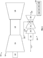
- FIG. 2 illustrates an example of an engine system 100 that can be part of the propulsion system 10 of FIG. 1 .
- the engine system 100 includes a gas turbine engine 120 and a secondary power unit 150.
- the gas turbine engine 120 is a simplified example of the gas turbine engine 20 of FIG. 1 and can include additional components beyond those depicted in the FIG. 2 .
- the gas turbine engine 120 includes a first compressor 124, a first combustor 126, and a first turbine 128. Similar to the compressor section 24 and the turbine section 28 of FIG. 1 , the first compressor 124 and the first turbine 128 can include multiple stages configured to operate at lower or higher pressures and can be linked through multiple spools configured to rotate at different speeds.
- the gas turbine engine 120 can also include an engine electric motor-generator 122 that can be operated in a motor mode or a generator mode.
- the engine electric motor-generator 122 may operate in a generator mode to provide electric power to one or more aircraft systems.
- the engine electric motor-generator 122 may operate in a motor mode, for example, to assist in starting the gas turbine engine 120 or to perform other operations, such as rotating components of the gas turbine engine 120 to assist in homogenizing temperatures after shutdown to avoid bowed rotor effects.
- the engine electric motor-generator 122 may be subdivided in some embodiments into one or more electric motors and one or more generators. Further, the engine electric motor-generator 122 may be coupled with the first compressor 124 through a gearbox, clutch, and/or other components (not depicted).
- the secondary power unit 150 can include a second compressor 154, a second combustor 156, a second turbine 158, a third compressor 160 coupled to the second compressor 154, and an electric motor-generator 152.
- the secondary power unit 150 can perform functions of a known auxiliary power unit and a known air cycle machine, such as providing starting support to the gas turbine engine 120 and providing cabin cooling air to an aircraft upon which the secondary power unit 150 is installed. Additionally, the secondary power unit 150 enables functionality that is not directly supported by known auxiliary power units and air cycle machines through multiple operating modes.
- the secondary power unit 150 can be coupled to the gas turbine engine 120 through multiple interfaces that are selectable depending upon the current conditions and operating mode based on gas turbine, engine system and/or aircraft operational parameters.
- the second compressor 154 of the secondary power unit 150 can be pneumatically coupled (e.g., using ducting) with the first compressor 124 of the gas turbine engine 120 such that the second compressor 154 can receive pressurized air 162 from the first compressor 124.
- pressurized air 164 from the first compressor 124 can be provided to the second turbine 158.
- One or more engine bleed taps of the first compressor 124 can be selected to provide one or more sources of pressurized air 162, 164.
- a same bleed tap of the first compressor 124 may provide pressurized air 162, 164 to either or both of the second compressor 154 and the second turbine 158.
- one or more valves may be controlled by a controller 180 to select an input energy source from the gas turbine engine 120, such as pressurized air 164.
- the second compressor 154 can receive air from an inlet 166 rather than pressurized air 162 from the first compressor 124.
- the inlet 166 may access air from an outside environment, for instance, bypass air.
- the second turbine 158 can receive waste heat 168 from the first turbine 128 as an input energy source.
- the waste heat 168 can be transferred directly as heated air extracted from the first turbine 128 or through a heat exchange system (not depicted), for instance, using a working fluid to transfer the waste heat 168 from the first turbine 128 to the second turbine 158.
- Valves or other control elements can be used to control the transfer of waste heat 168, for example, using one of more control signals commanded by the controller 180.
- the second combustor 156 can receive fuel 170 to combust to increase the temperature of gasses provided to the second turbine 158.
- the secondary power unit 150 can provide one or more output types.
- the electric motor-generator 152 can be configured in a generator mode to provide electric power 172 as the output type.
- the electric power 172 output by the electric motor-generator 152 can be used for various purposes on an aircraft that includes the engine system 100.
- the electric power 172 can be provided to the engine electric motor-generator 122 for electrical assist power during normal operation or during startup of the gas turbine engine 120.
- the electric motor-generator 152 may be subdivided in some embodiments into one or more electric motors and one or more generators.
- the electric motor-generator 152 may be coupled with the second compressor 154 and/or with the third compressor 160 through a gearbox, clutch, and/or other components (not depicted).
- the electric motor-generator 152 can receive electric power 172 as an input energy source.
- the motor mode can be used to start rotation of the second compressor 154, third compressor 160, and second turbine 158 prior to combustion of fuel 170 within the second combustor 156.
- the third compressor 160 may be a load or scroll compressor, for example, that produces compressed air 174 as the output type.
- the compressed air 174 may be used to assist in operation or starting of the gas turbine engine 120 or may have other aircraft uses. As one example, the compressed air 174 may be used to assist in conditioning cabin air, provide anti-icing, or other such applications.
- the controller 180 can control and monitor for fault conditions of the gas turbine engine 120 and/or the secondary power unit 150.
- the controller 180 can be integrally formed or otherwise in communication with a full authority digital engine control (FADEC) of the gas turbine engine 120.
- the controller 180 can include a processing system 182, a memory system 184, and an input/output interface 186.
- the controller 180 can also include various operational controls, such as a secondary power unit control 188 that identifies an operating mode and controls the selection of input energy source, output type, and/or other control parameters as further described herein. Integrating control aspects of the gas turbine engine 120 with control aspects of the secondary power unit 150 in controller 180 can enable shared enhancements that may not have been previously achievable in separately controlled subsystems.
- effects of shifting system loads in relation to system health and aircraft operating mode may enable the gas turbine engine 120 and/or the secondary power unit 150 to operate closer to peak efficiency, peak power and/or more efficient usage of the bleed, fuel and air inputs when controlled collectively.
- integration of operational control of the gas turbine engine 120 and secondary power unit 150 can enable combined power and thermal management system operation with greater efficiency and performance characteristics than may be realized in operating the gas turbine engine 120, secondary power unit 150, and associated subsystems separately.
- the processing system 182 can include any type or combination of central processing unit (CPU), including one or more of: a microprocessor, a digital signal processor (DSP), a microcontroller, an application specific integrated circuit (ASIC), a field programmable gate array (FPGA), or the like.
- the memory system 184 can store data and instructions that are executed by the processing system 182.
- the memory system 184 may include random access memory (RAM), read only memory (ROM), or other electronic, optical, magnetic, or any other computer readable medium onto which is stored data and algorithms in a non-transitory form.
- the input/output interface 186 is configured to collect sensor data from the one or more system sensors and interface with various components and subsystems of the engine system 100.
- the controller 180 provides a means for controlling aspects of the engine system 100.
- the means for controlling the engine system 100 can be otherwise subdivided, distributed, or combined with other control elements (not depicted).
- the controller 180 can apply control laws and access/update models to determine how to control and transfer power between the gas turbine engine 120, secondary power unit 150, and/or other aircraft components.
- sensed and/or derived parameters related to speed, flow rate, pressure ratios, temperature, thrust, and the like can be used to establish operational schedules and transition limits to maintain efficient operation of the gas turbine engine 120 in combination with the secondary power unit 150.
- a mode of operation of the gas turbine engine 120 such as idle, takeoff, climb, cruise, and descent can have different power settings, thrust requirements, flow requirements, and temperature effects.
- the secondary power unit control 188 can control one or more effectors that select an input energy source of the secondary power unit 150 and/or an output type of the secondary power unit 150.
- the secondary power unit control 188 can determine when a change in operating mode of the engine system 100 should result in a modified selection of the input energy source of the secondary power unit 150 and/or the output type of the secondary power unit 150.
- the input energy source can be fuel 170 and/or electric power 172, and the second compressor 154 can receive air at inlet 166 as part of a cold-start sequence.
- the input energy source can be fuel 170 and/or electric power 172, and the second compressor 154 can receive pressurized air 162 to ramp up speed of the second compressor 154 and second turbine 158 faster than may be achieved using air from inlet 166.
- the electric motor-generator 152 can be set to generator mode to provide electric power 172 to the engine electric motor-generator 122, or the compressed air 174 output of the third compressor 160 can be used to drive rotation of the first compressor 124.
- the input energy source of the secondary power unit 150 can be fuel 170 with air extracted from the inlet 166 to avoid extracting air from the gas turbine engine 120.
- the input energy source of the secondary power unit 150 can be waste heat 168 and/or pressurized air 164.
- fuel 170 may not flow to the second combustor 156, for instance, where the second turbine 158 receives waste heat 168 and/or pressurized air 164.
- the input energy source of the secondary power unit 150 can be fuel 170 with air extracted from the inlet 166 to avoid extracting air from the gas turbine engine 120.
- compressed air 174 can be generated using electric power 172 as an input in motor mode of the electric motor-generator 152, with pressurized air 162, 164, and/or waste heat 168.
- waste heat 168 as an input energy source can enhance power and thermal management collectively for the engine system 100.
- FIG. 3 illustrates an example of an engine system 200 that can be part of the propulsion system 10 of FIG. 1 .
- the engine system 200 includes the gas turbine engine 120 of FIG. 2 and a secondary power unit 250. Similar to the secondary power unit 150 of FIG. 2 , the secondary power unit 250 of FIG. 3 includes second compressor 154, second combustor 156, second turbine 158, third compressor 160 coupled to the second compressor 154, and electric motor-generator 152.
- the secondary power unit 250 also includes a heat exchanger 202.
- the heat exchanger 202 can receive pressurized air 204 from the first compressor 124 of the gas turbine engine 120 for energy extraction as an input energy source of the secondary power unit 150.
- the second turbine 158 of the secondary power unit 250 can output conditioned air 206 as a cooling source.
- the cooling source can be for an aircraft cabin, a cargo area, galley cooling, electronics system cooling, and/or other such uses.
- Other outputs types of the secondary power unit 250 can include electric power 172 output by the electric motor-generator 152 in generator mode and/or compressed air 174 output by the third compressor 160.
- controller 180 can control operation of the engine system 200, including the secondary power unit 250 and components used for input power selection and output type selection.
- FIG. 4 is a flow chart illustrating a method 300 for controlling an engine system 100, 200 including a gas turbine engine 120 and a secondary power unit 150, 250, in accordance with an embodiment.
- the method 300 may be performed, for example, by using engine system 100, 200 of FIG. 2-3 and/or other such systems (not depicted).
- an operating mode of an engine system 100 including a gas turbine engine 120 and a secondary power unit 150, 250 can be determined, for instance, by a controller 180.
- an input energy source and an output type of the secondary power unit 150, 250 are selected based on the operating mode. Events such as an engine start request, a restart request, an electric power demand, a compressed air demand, a conditioned air demand, and other such events can be used to establish an operating mode. For instance, if sufficient operating margin exists with respect to the gas turbine engine 120, the controller 180 may select an input energy source for the secondary power unit 150, 250 as pressurized air 162, 164, 204.
- the input energy source may be waste heat 168.
- a blend of input energy sources such as fuel 170, electric power 172, and waste heat 168 may be combined. Further, selections can be based on gas turbine, engine system and/or aircraft operational parameters.
- the secondary power unit 150, 250 can be controlled based on the input energy source and the output type as selected.
- the controller 180 can apply different control laws depending on the input energy source and the output type.
- a change in the operating mode of the engine system 100, 200 can be detected. For example, if a restart of the gas turbine engine 120 or secondary power unit 150, 250 is needed, a change in operating mode can result. Further, if a new demand is detected or a previous demand diminishes, a change in operating mode can result. Changes in power settings, such as idle, takeoff, climb, cruise, and descent, can result in operating mode changes with respect to the engine system 100, 200. Further, failure modes, such as a power loss elsewhere in the propulsion system 10 can result in an operating mode change.
- the input energy source and/or the output type of the secondary power unit 150, 250 can be modified based on the change in the operating mode.
- the secondary power unit 150, 250 may toggle the electric motor-generator 152 between motor mode and generator mode. If the operating margin of the gas turbine engine 120 is within a predetermined threshold, for example, the secondary power unit 150, 250, may switch from extracting pressurized air 162, 164, 204 to using fuel 170 as an input energy source.
- the operating mode can be further classified as a source electric power mode with the electric motor-generator 152 in a generator mode to provide electric power 172 as the output type.
- the operating mode can be a compressed air output mode with the third compressor 160 providing compressed air 174 as the output type.
- the input energy source of the secondary power unit 150 can be fuel 170 provided to the second combustor 156, waste heat 168 from the first turbine 128 to the second turbine 158, and/or pressurized air 164 from the first compressor 124 to the second turbine 158.
- the second compressor 154 can be configured to receive air from an inlet 166 and/or the first compressor 124 as pressurized air 162.
- the input energy source of the secondary power unit 150 can be fuel 170 provided to the second combustor 156, waste heat 168 from the first turbine 128 to the second turbine 158, pressurized air 164 from the first compressor 124 to the second turbine 158, and/or electric power 172 at the electric motor-generator 152 in a motor mode.
- the second compressor 154 can be configured to receive air from an inlet 166 and/or the first compressor 124 as pressurized air 162.
- the secondary power unit 250 includes a heat exchanger 202 configured to receive pressurized air 204 from the first compressor 124 as the input energy source
- the second turbine 158 can be configured to output conditioned air 206 as a cooling source.
- the electric motor-generator 152 can be in a generator mode to provide electric power 172 as the output type and/or the third compressor 160 can be configured to provide compressed air 174 as the output type in combination with outputting of the conditioned air 206.
Landscapes
- Engineering & Computer Science (AREA)
- Chemical & Material Sciences (AREA)
- Combustion & Propulsion (AREA)
- Mechanical Engineering (AREA)
- General Engineering & Computer Science (AREA)
- Aviation & Aerospace Engineering (AREA)
- Health & Medical Sciences (AREA)
- General Health & Medical Sciences (AREA)
- Pulmonology (AREA)
- Engine Equipment That Uses Special Cycles (AREA)
- Control Of Eletrric Generators (AREA)
Abstract
Description
- The subject matter disclosed herein generally relates to engine systems and, more particularly, to integrated operation of an engine and a secondary power unit.
- A propulsion system for an aircraft can include one or more gas turbine engines that combust fuel and provide propulsive power. Aircraft can also include an auxiliary power unit that typically generates compressed air while the aircraft is on the ground to assist with starting one or more gas turbine engines. An auxiliary power unit can also include an electric generator that may be used to provide electrical power to the aircraft prior to starting the gas turbine engines. Other systems on an aircraft can include an environmental control system that uses one or more air cycle machines to produce cooled conditioned air for a passenger cabin of the aircraft. Air cycle machines and an auxiliary power unit are typically installed in physically separate regions of the aircraft. For example, an auxiliary power unit may be installed in the tail section of the aircraft, while the air cycle machines may be installed in the fuselage of the aircraft physically closer to the gas turbine engines. An auxiliary power unit typically combusts fuel during operation, while an air cycle machine typically does not directly combust fuel.
- According to one embodiment, an engine system includes a gas turbine engine with a first compressor, a first combustor, and a first turbine. The engine system also includes a secondary power unit with a second compressor, a second combustor, a second turbine, a third compressor coupled to the second compressor, and an electric motor-generator, where the secondary power unit is coupled to the gas turbine engine. A controller is operable to determine an operating mode of the engine system, select an input energy source and an output type of the secondary power unit based on the operating mode, control the secondary power unit based on the input energy source and the output type as selected, detect a change in the operating mode of the engine system, and modify the input energy source and/or the output type of the secondary power unit based on the change in the operating mode.
- In addition to one or more of the features described above or below, or as an alternative, further embodiments may include where the operating mode includes a source electric power mode with the electric motor-generator in a generator mode to provide electric power as the output type.
- In addition to one or more of the features described above or below, or as an alternative, further embodiments may include where the input energy source of the secondary power unit includes fuel to the second combustor, waste heat from the first turbine to the second turbine, and/or pressurized air from the first compressor to the second turbine.
- In addition to one or more of the features described above or below, or as an alternative, further embodiments may include where the second compressor is configured to receive air from an inlet and/or the first compressor.
- In addition to one or more of the features described above or below, or as an alternative, further embodiments may include where the operating mode includes a compressed air output mode with the third compressor providing compressed air as the output type.
- In addition to one or more of the features described above or below, or as an alternative, further embodiments may include where the input energy source of the secondary power unit includes fuel to the second combustor, waste heat from the first turbine to the second turbine, pressurized air from the first compressor to the second turbine, and/or electric power at the electric motor-generator in a motor mode.
- In addition to one or more of the features described above or below, or as an alternative, further embodiments may include where the second compressor is configured to receive air from an inlet and/or the first compressor.
- In addition to one or more of the features described above or below, or as an alternative, further embodiments may include where the secondary power unit further includes a heat exchanger configured to receive pressurized air from the first compressor as the input energy source, and the second turbine is configured to output conditioned air as a cooling source.
- In addition to one or more of the features described above or below, or as an alternative, further embodiments may include where the electric motor-generator is in a generator mode to provide electric power as the output type.
- In addition to one or more of the features described above or below, or as an alternative, further embodiments may include where the third compressor is configured to provide compressed air as the output type.
- According to an embodiment, a method includes determining an operating mode of an engine system including a gas turbine engine and a secondary power unit, where the gas turbine engine includes a first compressor, a first combustor, and a first turbine. The secondary power unit includes a second compressor, a second combustor, a second turbine, a third compressor coupled to the second compressor, and an electric motor-generator, where the secondary power unit is coupled to the gas turbine engine. An input energy source and an output type of the secondary power unit are selected based on the operating mode. The secondary power unit is controlled based on the input energy source and the output type as selected. A change in the operating mode of the engine system can be detected. The input energy source and/or the output type of the secondary power unit can be modified based on the change in the operating mode.
- A technical effect of the apparatus, systems and methods is achieved by providing an engine system with a secondary power unit.
- The following descriptions should not be considered limiting in any way. With reference to the accompanying drawings, like elements are numbered alike:
-
FIG. 1 is a partial cross-sectional illustration of a gas turbine engine, in accordance with an embodiment of the disclosure; -
FIG. 2 is a schematic diagram of an engine system with a secondary power unit, in accordance with an embodiment of the disclosure; -
FIG. 3 is a schematic diagram of an engine system with a secondary power unit, in accordance with an embodiment of the disclosure; and -
FIG. 4 is a flow chart illustrating a method, in accordance with an embodiment of the disclosure. - A detailed description of one or more embodiments of the disclosed apparatus and method are presented herein by way of exemplification and not limitation with reference to the Figures.
-
FIG. 1 schematically illustrates agas turbine engine 20 as part of apropulsion system 10 that can include multiple instances of thegas turbine engine 20 and other components (not depicted). Thegas turbine engine 20 is disclosed herein as a two-spool turbofan that generally incorporates afan section 22, acompressor section 24, acombustor section 26 and aturbine section 28. Thefan section 22 drives air along a bypass flow path B in a bypass duct, while thecompressor section 24 drives air along a core flow path C for compression and communication into thecombustor section 26 then expansion through theturbine section 28. Although depicted as a two-spool turbofan gas turbine engine in the disclosed non-limiting embodiment, it should be understood that the concepts described herein are not limited to use with two-spool turbofans as the teachings may be applied to other types of turbine engines including three-spool architectures. - The
exemplary engine 20 generally includes alow speed spool 30 and ahigh speed spool 32 mounted for rotation about an engine central longitudinal axis A relative to an enginestatic structure 36 viaseveral bearing systems 38. It should be understood thatvarious bearing systems 38 at various locations may alternatively or additionally be provided, and the location ofbearing systems 38 may be varied as appropriate to the application. - The
low speed spool 30 generally includes aninner shaft 40 that interconnects afan 42, alow pressure compressor 44 and alow pressure turbine 46. Theinner shaft 40 is connected to thefan 42 through a speed change mechanism, which in exemplarygas turbine engine 20 is illustrated as a gearedarchitecture 48 to drive thefan 42 at a lower speed than thelow speed spool 30. Thehigh speed spool 32 includes anouter shaft 50 that interconnects ahigh pressure compressor 52 andhigh pressure turbine 54. Acombustor 56 is arranged inexemplary gas turbine 20 between thehigh pressure compressor 52 and thehigh pressure turbine 54. An enginestatic structure 36 is arranged generally between thehigh pressure turbine 54 and thelow pressure turbine 46. The enginestatic structure 36 further supports bearingsystems 38 in theturbine section 28. Theinner shaft 40 and theouter shaft 50 are concentric and rotate viabearing systems 38 about the engine central longitudinal axis A which is collinear with their longitudinal axes. - The core airflow is compressed by the
low pressure compressor 44 then thehigh pressure compressor 52, mixed and burned with fuel in thecombustor 56, then expanded over thehigh pressure turbine 54 andlow pressure turbine 46. Theturbines low speed spool 30 andhigh speed spool 32 in response to the expansion. It will be appreciated that each of the positions of thefan section 22,compressor section 24,combustor section 26,turbine section 28, and fandrive gear system 48 may be varied. For example,gear system 48 may be located aft ofcombustor section 26 or even aft ofturbine section 28, andfan section 22 may be positioned forward or aft of the location ofgear system 48. - The
engine 20 in one example is a high-bypass geared aircraft engine. In a further example, theengine 20 bypass ratio is greater than about six (6), with an example embodiment being greater than about ten (10), the gearedarchitecture 48 is an epicyclic gear train, such as a planetary gear system or other gear system, with a gear reduction ratio of greater than about 2.3 and thelow pressure turbine 46 has a pressure ratio that is greater than about five. In one disclosed embodiment, theengine 20 bypass ratio is greater than about ten (10:1), the fan diameter is significantly larger than that of thelow pressure compressor 44, and thelow pressure turbine 46 has a pressure ratio that is greater than about five 5:1.Low pressure turbine 46 pressure ratio is pressure measured prior to inlet oflow pressure turbine 46 as related to the pressure at the outlet of thelow pressure turbine 46 prior to anexhaust nozzle 60. The gearedarchitecture 48 may be an epicycle gear train, such as a planetary gear system or other gear system, with a gear reduction ratio of greater than about 2.3:1. It should be understood, however, that the above parameters are only exemplary of one embodiment of a geared architecture engine and that the present disclosure is applicable to other gas turbine engines including direct drive turbofans. - A significant amount of thrust is provided by the bypass flow B due to the high bypass ratio. The
fan section 22 of theengine 20 is designed for a particular flight condition--typically cruise at about 0.8Mach and about 35,000 feet (10,668 meters). The flight condition of 0.8 Mach and 35,000 ft (10,668 meters), with the engine at its best fuel consumption--also known as "bucket cruise Thrust Specific Fuel Consumption ('TSFC')"--is the industry standard parameter of lbm of fuel being burned divided by lbf of thrust the engine produces at that minimum point. "Low fan pressure ratio" is the pressure ratio across the fan blade alone, without a Fan Exit Guide Vane ("FEGV") system. The low fan pressure ratio as disclosed herein according to one non-limiting embodiment is less than about 1.45. "Low corrected fan tip speed" is the actual fan tip speed in ft/sec divided by an industry standard temperature correction of [(Tram °R)/(518.7 °R)]^0.5. The "Low corrected fan tip speed" as disclosed herein according to one non-limiting embodiment is less than about 1150 ft/second (350.5 m/sec). - While the example of
FIG. 1 illustrates one example of thegas turbine engine 20, it will be understood that any number of spools, inclusion or omission of thegear system 48, and/or other elements and subsystems are contemplated. Further, systems described herein can be used in a variety of applications and need not be limited to gas turbine engines for aircraft applications. For example, systems described herein can be included in power generation systems, which may be ground-based as a fixed position or mobile system, and other such applications. -
FIG. 2 illustrates an example of anengine system 100 that can be part of thepropulsion system 10 ofFIG. 1 . Theengine system 100 includes agas turbine engine 120 and asecondary power unit 150. Thegas turbine engine 120 is a simplified example of thegas turbine engine 20 ofFIG. 1 and can include additional components beyond those depicted in theFIG. 2 . In the example ofFIG. 2 , thegas turbine engine 120 includes afirst compressor 124, afirst combustor 126, and afirst turbine 128. Similar to thecompressor section 24 and theturbine section 28 ofFIG. 1 , thefirst compressor 124 and thefirst turbine 128 can include multiple stages configured to operate at lower or higher pressures and can be linked through multiple spools configured to rotate at different speeds. Thegas turbine engine 120 can also include an engine electric motor-generator 122 that can be operated in a motor mode or a generator mode. For example, when thegas turbine engine 120 has been started, the engine electric motor-generator 122 may operate in a generator mode to provide electric power to one or more aircraft systems. The engine electric motor-generator 122 may operate in a motor mode, for example, to assist in starting thegas turbine engine 120 or to perform other operations, such as rotating components of thegas turbine engine 120 to assist in homogenizing temperatures after shutdown to avoid bowed rotor effects. Although depicted as a single component, the engine electric motor-generator 122 may be subdivided in some embodiments into one or more electric motors and one or more generators. Further, the engine electric motor-generator 122 may be coupled with thefirst compressor 124 through a gearbox, clutch, and/or other components (not depicted). - The
secondary power unit 150 can include asecond compressor 154, asecond combustor 156, asecond turbine 158, athird compressor 160 coupled to thesecond compressor 154, and an electric motor-generator 152. Thesecondary power unit 150 can perform functions of a known auxiliary power unit and a known air cycle machine, such as providing starting support to thegas turbine engine 120 and providing cabin cooling air to an aircraft upon which thesecondary power unit 150 is installed. Additionally, thesecondary power unit 150 enables functionality that is not directly supported by known auxiliary power units and air cycle machines through multiple operating modes. Thesecondary power unit 150 can be coupled to thegas turbine engine 120 through multiple interfaces that are selectable depending upon the current conditions and operating mode based on gas turbine, engine system and/or aircraft operational parameters. For example, thesecond compressor 154 of thesecondary power unit 150 can be pneumatically coupled (e.g., using ducting) with thefirst compressor 124 of thegas turbine engine 120 such that thesecond compressor 154 can receivepressurized air 162 from thefirst compressor 124. Further,pressurized air 164 from thefirst compressor 124 can be provided to thesecond turbine 158. One or more engine bleed taps of thefirst compressor 124 can be selected to provide one or more sources ofpressurized air first compressor 124 may providepressurized air second compressor 154 and thesecond turbine 158. For instance, one or more valves (not depicted) may be controlled by acontroller 180 to select an input energy source from thegas turbine engine 120, such aspressurized air 164. - In some modes of operation, the
second compressor 154 can receive air from aninlet 166 rather thanpressurized air 162 from thefirst compressor 124. Theinlet 166 may access air from an outside environment, for instance, bypass air. Similarly, rather than receivingpressurized air 164 from thefirst compressor 124 or heated air from thesecond combustor 156, thesecond turbine 158 can receivewaste heat 168 from thefirst turbine 128 as an input energy source. Thewaste heat 168 can be transferred directly as heated air extracted from thefirst turbine 128 or through a heat exchange system (not depicted), for instance, using a working fluid to transfer thewaste heat 168 from thefirst turbine 128 to thesecond turbine 158. Valves or other control elements (not depicted) can be used to control the transfer ofwaste heat 168, for example, using one of more control signals commanded by thecontroller 180. As another input energy source, thesecond combustor 156 can receivefuel 170 to combust to increase the temperature of gasses provided to thesecond turbine 158. - In the example of
FIG. 2 , thesecondary power unit 150 can provide one or more output types. For example, the electric motor-generator 152 can be configured in a generator mode to provideelectric power 172 as the output type. Theelectric power 172 output by the electric motor-generator 152 can be used for various purposes on an aircraft that includes theengine system 100. For example, theelectric power 172 can be provided to the engine electric motor-generator 122 for electrical assist power during normal operation or during startup of thegas turbine engine 120. Although depicted as a single component, the electric motor-generator 152 may be subdivided in some embodiments into one or more electric motors and one or more generators. Further, the electric motor-generator 152 may be coupled with thesecond compressor 154 and/or with thethird compressor 160 through a gearbox, clutch, and/or other components (not depicted). In motor mode, the electric motor-generator 152 can receiveelectric power 172 as an input energy source. For example, the motor mode can be used to start rotation of thesecond compressor 154,third compressor 160, andsecond turbine 158 prior to combustion offuel 170 within thesecond combustor 156. - The
third compressor 160 may be a load or scroll compressor, for example, that produces compressedair 174 as the output type. Thecompressed air 174 may be used to assist in operation or starting of thegas turbine engine 120 or may have other aircraft uses. As one example, thecompressed air 174 may be used to assist in conditioning cabin air, provide anti-icing, or other such applications. - In embodiments, the
controller 180 can control and monitor for fault conditions of thegas turbine engine 120 and/or thesecondary power unit 150. For example, thecontroller 180 can be integrally formed or otherwise in communication with a full authority digital engine control (FADEC) of thegas turbine engine 120. In embodiments, thecontroller 180 can include aprocessing system 182, amemory system 184, and an input/output interface 186. Thecontroller 180 can also include various operational controls, such as a secondarypower unit control 188 that identifies an operating mode and controls the selection of input energy source, output type, and/or other control parameters as further described herein. Integrating control aspects of thegas turbine engine 120 with control aspects of thesecondary power unit 150 incontroller 180 can enable shared enhancements that may not have been previously achievable in separately controlled subsystems. For example, effects of shifting system loads in relation to system health and aircraft operating mode may enable thegas turbine engine 120 and/or thesecondary power unit 150 to operate closer to peak efficiency, peak power and/or more efficient usage of the bleed, fuel and air inputs when controlled collectively. Further, integration of operational control of thegas turbine engine 120 andsecondary power unit 150 can enable combined power and thermal management system operation with greater efficiency and performance characteristics than may be realized in operating thegas turbine engine 120,secondary power unit 150, and associated subsystems separately. - The
processing system 182 can include any type or combination of central processing unit (CPU), including one or more of: a microprocessor, a digital signal processor (DSP), a microcontroller, an application specific integrated circuit (ASIC), a field programmable gate array (FPGA), or the like. Thememory system 184 can store data and instructions that are executed by theprocessing system 182. In embodiments, thememory system 184 may include random access memory (RAM), read only memory (ROM), or other electronic, optical, magnetic, or any other computer readable medium onto which is stored data and algorithms in a non-transitory form. The input/output interface 186 is configured to collect sensor data from the one or more system sensors and interface with various components and subsystems of theengine system 100. Thecontroller 180 provides a means for controlling aspects of theengine system 100. The means for controlling theengine system 100 can be otherwise subdivided, distributed, or combined with other control elements (not depicted). - As one example, the
controller 180 can apply control laws and access/update models to determine how to control and transfer power between thegas turbine engine 120,secondary power unit 150, and/or other aircraft components. For example, sensed and/or derived parameters related to speed, flow rate, pressure ratios, temperature, thrust, and the like can be used to establish operational schedules and transition limits to maintain efficient operation of thegas turbine engine 120 in combination with thesecondary power unit 150. For instance, a mode of operation of thegas turbine engine 120, such as idle, takeoff, climb, cruise, and descent can have different power settings, thrust requirements, flow requirements, and temperature effects. The secondarypower unit control 188 can control one or more effectors that select an input energy source of thesecondary power unit 150 and/or an output type of thesecondary power unit 150. The secondarypower unit control 188 can determine when a change in operating mode of theengine system 100 should result in a modified selection of the input energy source of thesecondary power unit 150 and/or the output type of thesecondary power unit 150. - For example, during a ground start operating mode of the
secondary power unit 150, the input energy source can befuel 170 and/orelectric power 172, and thesecond compressor 154 can receive air atinlet 166 as part of a cold-start sequence. During an engine-assisted start operating mode of thesecondary power unit 150, the input energy source can befuel 170 and/orelectric power 172, and thesecond compressor 154 can receivepressurized air 162 to ramp up speed of thesecond compressor 154 andsecond turbine 158 faster than may be achieved using air frominlet 166. To assist with starting of thegas turbine engine 120 using thesecondary power unit 150, the electric motor-generator 152 can be set to generator mode to provideelectric power 172 to the engine electric motor-generator 122, or thecompressed air 174 output of thethird compressor 160 can be used to drive rotation of thefirst compressor 124. In operating modes that outputelectric power 172, various configurations can be supported, for example, the input energy source of thesecondary power unit 150 can befuel 170 with air extracted from theinlet 166 to avoid extracting air from thegas turbine engine 120. Further, the input energy source of thesecondary power unit 150 can bewaste heat 168 and/orpressurized air 164. In some modes of operation,fuel 170 may not flow to thesecond combustor 156, for instance, where thesecond turbine 158 receiveswaste heat 168 and/orpressurized air 164. When the output type is compressedair 174, the input energy source of thesecondary power unit 150 can befuel 170 with air extracted from theinlet 166 to avoid extracting air from thegas turbine engine 120. Further,compressed air 174 can be generated usingelectric power 172 as an input in motor mode of the electric motor-generator 152, withpressurized air waste heat 168. Usingwaste heat 168 as an input energy source can enhance power and thermal management collectively for theengine system 100. -
FIG. 3 illustrates an example of anengine system 200 that can be part of thepropulsion system 10 ofFIG. 1 . Theengine system 200 includes thegas turbine engine 120 ofFIG. 2 and asecondary power unit 250. Similar to thesecondary power unit 150 ofFIG. 2 , thesecondary power unit 250 ofFIG. 3 includessecond compressor 154,second combustor 156,second turbine 158,third compressor 160 coupled to thesecond compressor 154, and electric motor-generator 152. Thesecondary power unit 250 also includes aheat exchanger 202. Theheat exchanger 202 can receivepressurized air 204 from thefirst compressor 124 of thegas turbine engine 120 for energy extraction as an input energy source of thesecondary power unit 150. Thesecond turbine 158 of thesecondary power unit 250 can output conditionedair 206 as a cooling source. The cooling source can be for an aircraft cabin, a cargo area, galley cooling, electronics system cooling, and/or other such uses. Other outputs types of thesecondary power unit 250 can includeelectric power 172 output by the electric motor-generator 152 in generator mode and/orcompressed air 174 output by thethird compressor 160. Similar to the example ofFIG. 2 ,controller 180 can control operation of theengine system 200, including thesecondary power unit 250 and components used for input power selection and output type selection. - Referring now to
FIG. 4 with continued reference toFIGS. 1-3 ,FIG. 4 is a flow chart illustrating amethod 300 for controlling anengine system gas turbine engine 120 and asecondary power unit method 300 may be performed, for example, by usingengine system FIG. 2-3 and/or other such systems (not depicted). - At
block 302, an operating mode of anengine system 100 including agas turbine engine 120 and asecondary power unit controller 180. Atblock 304, an input energy source and an output type of thesecondary power unit gas turbine engine 120, thecontroller 180 may select an input energy source for thesecondary power unit pressurized air waste heat 168 is sufficiently high (e.g., based on a temperature threshold), then the input energy source may bewaste heat 168. In some instances, a blend of input energy sources, such asfuel 170,electric power 172, andwaste heat 168 may be combined. Further, selections can be based on gas turbine, engine system and/or aircraft operational parameters. - At
block 306, thesecondary power unit controller 180 can apply different control laws depending on the input energy source and the output type. - At
block 308, a change in the operating mode of theengine system gas turbine engine 120 orsecondary power unit engine system propulsion system 10 can result in an operating mode change. - At
block 310, the input energy source and/or the output type of thesecondary power unit secondary power unit generator 152 between motor mode and generator mode. If the operating margin of thegas turbine engine 120 is within a predetermined threshold, for example, thesecondary power unit pressurized air fuel 170 as an input energy source. The operating mode can be further classified as a source electric power mode with the electric motor-generator 152 in a generator mode to provideelectric power 172 as the output type. As another example, the operating mode can be a compressed air output mode with thethird compressor 160 providingcompressed air 174 as the output type. - In the source electric power mode, the input energy source of the
secondary power unit 150 can befuel 170 provided to thesecond combustor 156,waste heat 168 from thefirst turbine 128 to thesecond turbine 158, and/orpressurized air 164 from thefirst compressor 124 to thesecond turbine 158. Thesecond compressor 154 can be configured to receive air from aninlet 166 and/or thefirst compressor 124 aspressurized air 162. - In compressed air output mode, the input energy source of the
secondary power unit 150 can befuel 170 provided to thesecond combustor 156,waste heat 168 from thefirst turbine 128 to thesecond turbine 158,pressurized air 164 from thefirst compressor 124 to thesecond turbine 158, and/orelectric power 172 at the electric motor-generator 152 in a motor mode. Thesecond compressor 154 can be configured to receive air from aninlet 166 and/or thefirst compressor 124 aspressurized air 162. - Where the
secondary power unit 250 includes aheat exchanger 202 configured to receivepressurized air 204 from thefirst compressor 124 as the input energy source, thesecond turbine 158 can be configured to output conditionedair 206 as a cooling source. The electric motor-generator 152 can be in a generator mode to provideelectric power 172 as the output type and/or thethird compressor 160 can be configured to providecompressed air 174 as the output type in combination with outputting of theconditioned air 206. - While the above description has described the flow process of
FIG. 4 in a particular order, it should be appreciated that unless otherwise specifically required in the attached claims that the ordering of the steps may be varied. - The term "about" is intended to include the degree of error associated with measurement of the particular quantity based upon the equipment available at the time of filing the application.
- The terminology used herein is for the purpose of describing particular embodiments only and is not intended to be limiting of the present disclosure. As used herein, the singular forms "a", "an" and "the" are intended to include the plural forms as well, unless the context clearly indicates otherwise. It will be further understood that the terms "comprises" and/or "comprising," when used in this specification, specify the presence of stated features, integers, steps, operations, elements, and/or components, but do not preclude the presence or addition of one or more other features, integers, steps, operations, element components, and/or groups thereof.
- While the present disclosure has been described with reference to an exemplary embodiment or embodiments, it will be understood by those skilled in the art that various changes may be made and equivalents may be substituted for elements thereof without departing from the scope of the present disclosure. In addition, many modifications may be made to adapt a particular situation or material to the teachings of the present disclosure without departing from the essential scope thereof. Therefore, it is intended that the present disclosure not be limited to the particular embodiment disclosed as the best mode contemplated for carrying out this present disclosure, but that the present disclosure will include all embodiments falling within the scope of the claims.
Claims (15)
- An engine system (100, 200) comprising:a gas turbine engine (120) comprising a first compressor (124), a first combustor (126), and a first turbine (128);a secondary power unit (150, 250) comprising a second compressor (154), a second combustor (156), a second turbine (158), a third compressor (160) coupled to the second compressor, and an electric motor-generator (152), wherein the secondary power unit is coupled to the gas turbine engine (120); anda controller (180) operable to determine an operating mode of the engine system, select an input energy source and an output type of the secondary power unit based on the operating mode, control the secondary power unit based on the input energy source and the output type as selected, detect a change in the operating mode of the engine system, and modify the input energy source and/or the output type of the secondary power unit based on the change in the operating mode.
- The engine system of claim 1, wherein the operating mode comprises a source electric power mode with the electric motor-generator (152) in a generator mode to provide electric power as the output type.
- The engine system of claim 2, wherein the input energy source of the secondary power unit (150) comprises fuel (170) to the second combustor (156), waste heat (168) from the first turbine (128) to the second turbine (158), and/or pressurized air (164) from the first compressor (124) to the second turbine (158).
- The engine system of claim 2 or 3, wherein the second compressor (154) is configured to receive air from an inlet (166) and/or the first compressor (124).
- The engine system of any preceding claim, wherein the operating mode comprises a compressed air output mode with the third compressor (160) providing compressed air (174) as the output type, optionally
wherein the input energy source of the secondary power unit (150) comprises fuel (170) to the second combustor (156), waste heat (168) from the first turbine (128) to the second turbine (158), pressurized air (162) from the first compressor (124) to the second turbine (158), and/or electric power (172) at the electric motor-generator (152) in a motor mode. - The engine system of claim 5, wherein the second compressor (154) is configured to receive air from an inlet (166) and/or the first compressor (124).
- The engine system of any preceding claim, wherein the secondary power unit (250) further comprises a heat exchanger (202) configured to receive pressurized air (204) from the first compressor (124) as the input energy source, and the second turbine (158) is configured to output conditioned air (206) as a cooling source, optionally
wherein the electric motor-generator (152) is in a generator mode to provide electric power (172) as the output type. - The engine system of claim 7, wherein the third compressor (160) is configured to provide compressed air (174) as the output type.
- A method (300) comprising:determining (302) an operating mode of an engine system comprising a gas turbine engine (120) and a secondary power unit (150, 250), wherein the gas turbine engine comprises a first compressor (124), a first combustor (126), and a first turbine (128), and the secondary power unit comprises a second compressor (154), a second combustor (156), a second turbine (158), a third compressor (160) coupled to the second compressor, and an electric motor-generator (152), wherein the secondary power unit is coupled to the gas turbine engine;selecting (304) an input energy source and an output type of the secondary power unit based on the operating mode;controlling (306) the secondary power unit based on the input energy source and the output type as selected;detecting (308) a change in the operating mode of the engine system; andmodifying (310) the input energy source and/or the output type of the secondary power unit based on the change in the operating mode.
- The method of claim 9, wherein the operating mode comprises a source electric power mode with the electric motor-generator (152) in a generator mode to provide electric power (172) as the output type.
- The method of claim 10, wherein the input energy source of the secondary power unit (150) comprises fuel (170) to the second combustor (156), waste heat (168) from the first turbine (128) to the second turbine (158), and/or pressurized air (164) from the first compressor (124) to the second turbine (158).
- The method of claim 10 or 11, wherein the second compressor (154) is configured to receive air from an inlet (166) and/or the first compressor (124).
- The method of any of claims 9 to 12, wherein the operating mode comprises a compressed air output mode with the third compressor (160) providing compressed air (174) as the output type, optionally
wherein the input energy source of the secondary power unit (150) comprises fuel (170) to the second combustor (156), waste heat (168) from the first turbine (128) to the second turbine (158), pressurized air (164) from the first compressor (124) to the second turbine (158), and/or electric power (172) at the electric motor-generator (152) in a motor mode. - The method of claim 13, wherein the second compressor (154) is configured to receive air from an inlet (166) and/or the first compressor (124).
- The method of any of claims 9 to 14, wherein the secondary power unit (250) further comprises a heat exchanger (202) configured to receive pressurized air (204) from the first compressor (124) as the input energy source, and the second turbine (158) is configured to output conditioned air (206) as a cooling source, optionally
wherein the electric motor-generator (152) is in a generator mode to provide electric power (172) as the output type, and/or
wherein the third compressor (160) is configured to provide compressed air (174) as the output type.
Priority Applications (1)
| Application Number | Priority Date | Filing Date | Title |
|---|---|---|---|
| EP25216787.9A EP4671128A3 (en) | 2020-02-14 | 2021-02-15 | Engine and secondary power unit integrated operation |
Applications Claiming Priority (1)
| Application Number | Priority Date | Filing Date | Title |
|---|---|---|---|
| US16/791,106 US11795872B2 (en) | 2020-02-14 | 2020-02-14 | Engine and secondary power unit integrated operation |
Related Child Applications (1)
| Application Number | Title | Priority Date | Filing Date |
|---|---|---|---|
| EP25216787.9A Division EP4671128A3 (en) | 2020-02-14 | 2021-02-15 | Engine and secondary power unit integrated operation |
Publications (2)
| Publication Number | Publication Date |
|---|---|
| EP3865692A1 true EP3865692A1 (en) | 2021-08-18 |
| EP3865692B1 EP3865692B1 (en) | 2025-11-19 |
Family
ID=74625929
Family Applications (2)
| Application Number | Title | Priority Date | Filing Date |
|---|---|---|---|
| EP25216787.9A Pending EP4671128A3 (en) | 2020-02-14 | 2021-02-15 | Engine and secondary power unit integrated operation |
| EP21157222.7A Active EP3865692B1 (en) | 2020-02-14 | 2021-02-15 | Engine and secondary power unit integrated operation |
Family Applications Before (1)
| Application Number | Title | Priority Date | Filing Date |
|---|---|---|---|
| EP25216787.9A Pending EP4671128A3 (en) | 2020-02-14 | 2021-02-15 | Engine and secondary power unit integrated operation |
Country Status (2)
| Country | Link |
|---|---|
| US (2) | US11795872B2 (en) |
| EP (2) | EP4671128A3 (en) |
Families Citing this family (7)
| Publication number | Priority date | Publication date | Assignee | Title |
|---|---|---|---|---|
| US11795872B2 (en) | 2020-02-14 | 2023-10-24 | Rtx Corporation | Engine and secondary power unit integrated operation |
| US12187441B2 (en) * | 2021-04-27 | 2025-01-07 | The Boeing Company | Aircraft environmental control systems having electrically powered ram circuit fans |
| FR3125799A1 (en) * | 2021-11-10 | 2023-02-03 | Airbus Operations | AUXILIARY POWER UNIT FOR AN AIRCRAFT |
| FR3132538B1 (en) * | 2022-02-04 | 2023-12-22 | Safran Aircraft Engines | Process for controlling a gas turbine engine |
| US12428164B2 (en) * | 2022-05-16 | 2025-09-30 | General Electric Company | Environmental control system having a fuel cell assembly |
| DE102023133324A1 (en) * | 2023-11-29 | 2025-06-05 | MTU Aero Engines AG | Turbomachine for aircraft propulsion |
| US12410748B1 (en) | 2024-05-21 | 2025-09-09 | Rtx Corporation | Boost compressor augmentation for hybrid electric thermal management systems |
Citations (3)
| Publication number | Priority date | Publication date | Assignee | Title |
|---|---|---|---|---|
| US5813630A (en) * | 1996-09-27 | 1998-09-29 | Mcdonnell Douglas Corporation | Multi-mode secondary power unit |
| US5899085A (en) * | 1997-08-01 | 1999-05-04 | Mcdonnell Douglas Corporation | Integrated air conditioning and power unit |
| US20170106985A1 (en) * | 2015-08-07 | 2017-04-20 | Rolls-Royce Plc | Aircraft pneumatic system |
Family Cites Families (11)
| Publication number | Priority date | Publication date | Assignee | Title |
|---|---|---|---|---|
| US6735951B2 (en) * | 2002-01-04 | 2004-05-18 | Hamilton Sundstrand Corporation | Turbocharged auxiliary power unit with controlled high speed spool |
| US7121078B2 (en) * | 2003-01-28 | 2006-10-17 | General Electric Company | Methods and apparatus for operating gas turbine engines |
| US7464533B2 (en) * | 2003-01-28 | 2008-12-16 | General Electric Company | Apparatus for operating gas turbine engines |
| US6971241B2 (en) * | 2003-11-10 | 2005-12-06 | Honeywell International Inc. | Dual mode power unit having a combustor bypass system |
| US7739864B2 (en) * | 2006-11-07 | 2010-06-22 | General Electric Company | Systems and methods for power generation with carbon dioxide isolation |
| US20100170262A1 (en) | 2009-01-06 | 2010-07-08 | Kaslusky Scott F | Aircraft power and thermal management system with electric co-generation |
| FR2995635B1 (en) | 2012-09-17 | 2025-02-14 | Microturbo | DEVICE AND METHOD FOR PROVIDING NON-PROPULSION POWER FOR AN AIRCRAFT |
| US9822670B2 (en) * | 2015-03-19 | 2017-11-21 | General Electric Company | Power generation system having compressor creating excess air flow and turbo-expander for cooling inlet air |
| EP3273006B1 (en) * | 2016-07-21 | 2019-07-03 | United Technologies Corporation | Alternating starter use during multi-engine motoring |
| CA3038718C (en) | 2016-09-29 | 2023-12-05 | Airbus Operations, S.L. | Auxiliary air supply for an aircraft |
| US11795872B2 (en) | 2020-02-14 | 2023-10-24 | Rtx Corporation | Engine and secondary power unit integrated operation |
-
2020
- 2020-02-14 US US16/791,106 patent/US11795872B2/en active Active
-
2021
- 2021-02-15 EP EP25216787.9A patent/EP4671128A3/en active Pending
- 2021-02-15 EP EP21157222.7A patent/EP3865692B1/en active Active
-
2023
- 2023-08-31 US US18/240,505 patent/US12123344B2/en active Active
Patent Citations (3)
| Publication number | Priority date | Publication date | Assignee | Title |
|---|---|---|---|---|
| US5813630A (en) * | 1996-09-27 | 1998-09-29 | Mcdonnell Douglas Corporation | Multi-mode secondary power unit |
| US5899085A (en) * | 1997-08-01 | 1999-05-04 | Mcdonnell Douglas Corporation | Integrated air conditioning and power unit |
| US20170106985A1 (en) * | 2015-08-07 | 2017-04-20 | Rolls-Royce Plc | Aircraft pneumatic system |
Also Published As
| Publication number | Publication date |
|---|---|
| EP4671128A2 (en) | 2025-12-31 |
| EP4671128A3 (en) | 2026-04-01 |
| US12123344B2 (en) | 2024-10-22 |
| US11795872B2 (en) | 2023-10-24 |
| US20210254545A1 (en) | 2021-08-19 |
| US20230407783A1 (en) | 2023-12-21 |
| EP3865692B1 (en) | 2025-11-19 |
Similar Documents
| Publication | Publication Date | Title |
|---|---|---|
| EP3789603B1 (en) | Electric power assist for in-flight engine re-start | |
| US12123344B2 (en) | Engine and secondary power unit integrated operation | |
| EP3954889B1 (en) | Hybrid gas turbine engine system powered warm-up | |
| EP3693571B1 (en) | Transient operation control of a hybrid gas turbine engine | |
| EP3623203B1 (en) | Hybrid electric aircraft battery charging | |
| US20200263604A1 (en) | Gas turbine engine buffer system | |
| EP4227515B1 (en) | Turbine engine with inverse brayton cycle | |
| EP4102044A2 (en) | Hybrid electric engine power distribution | |
| EP3767090B2 (en) | Compressor operability control for hybrid electric propulsion | |
| US12168519B2 (en) | Hybrid-electric single engine descent failure management | |
| US12326111B2 (en) | Hybrid-electric single engine descent failure management | |
| US11557995B2 (en) | Aircraft engine power-assist start stability control | |
| EP3779150B1 (en) | Material fatigue improvement for hybrid propulsion systems | |
| US11649763B1 (en) | Rating control architecture and method for hybrid electric engine |
Legal Events
| Date | Code | Title | Description |
|---|---|---|---|
| PUAI | Public reference made under article 153(3) epc to a published international application that has entered the european phase |
Free format text: ORIGINAL CODE: 0009012 |
|
| STAA | Information on the status of an ep patent application or granted ep patent |
Free format text: STATUS: THE APPLICATION HAS BEEN PUBLISHED |
|
| AK | Designated contracting states |
Kind code of ref document: A1 Designated state(s): AL AT BE BG CH CY CZ DE DK EE ES FI FR GB GR HR HU IE IS IT LI LT LU LV MC MK MT NL NO PL PT RO RS SE SI SK SM TR |
|
| STAA | Information on the status of an ep patent application or granted ep patent |
Free format text: STATUS: REQUEST FOR EXAMINATION WAS MADE |
|
| 17P | Request for examination filed |
Effective date: 20220218 |
|
| RBV | Designated contracting states (corrected) |
Designated state(s): AL AT BE BG CH CY CZ DE DK EE ES FI FR GB GR HR HU IE IS IT LI LT LU LV MC MK MT NL NO PL PT RO RS SE SI SK SM TR |
|
| STAA | Information on the status of an ep patent application or granted ep patent |
Free format text: STATUS: EXAMINATION IS IN PROGRESS |
|
| 17Q | First examination report despatched |
Effective date: 20230914 |
|
| RAP3 | Party data changed (applicant data changed or rights of an application transferred) |
Owner name: RTX CORPORATION |
|
| GRAP | Despatch of communication of intention to grant a patent |
Free format text: ORIGINAL CODE: EPIDOSNIGR1 |
|
| STAA | Information on the status of an ep patent application or granted ep patent |
Free format text: STATUS: GRANT OF PATENT IS INTENDED |
|
| INTG | Intention to grant announced |
Effective date: 20250613 |
|
| GRAS | Grant fee paid |
Free format text: ORIGINAL CODE: EPIDOSNIGR3 |
|
| GRAA | (expected) grant |
Free format text: ORIGINAL CODE: 0009210 |
|
| STAA | Information on the status of an ep patent application or granted ep patent |
Free format text: STATUS: THE PATENT HAS BEEN GRANTED |
|
| AK | Designated contracting states |
Kind code of ref document: B1 Designated state(s): AL AT BE BG CH CY CZ DE DK EE ES FI FR GB GR HR HU IE IS IT LI LT LU LV MC MK MT NL NO PL PT RO RS SE SI SK SM TR |
|
| REG | Reference to a national code |
Ref country code: CH Ref legal event code: F10 Free format text: ST27 STATUS EVENT CODE: U-0-0-F10-F00 (AS PROVIDED BY THE NATIONAL OFFICE) Effective date: 20251119 Ref country code: GB Ref legal event code: FG4D |
|
| REG | Reference to a national code |
Ref country code: DE Ref legal event code: R096 Ref document number: 602021042494 Country of ref document: DE |
|
| REG | Reference to a national code |
Ref country code: IE Ref legal event code: FG4D |
|
| REG | Reference to a national code |
Ref country code: NL Ref legal event code: MP Effective date: 20251119 |
|
| PGFP | Annual fee paid to national office [announced via postgrant information from national office to epo] |
Ref country code: GB Payment date: 20260121 Year of fee payment: 6 |
|
| PG25 | Lapsed in a contracting state [announced via postgrant information from national office to epo] |
Ref country code: ES Free format text: LAPSE BECAUSE OF FAILURE TO SUBMIT A TRANSLATION OF THE DESCRIPTION OR TO PAY THE FEE WITHIN THE PRESCRIBED TIME-LIMIT Effective date: 20251119 |
|
| REG | Reference to a national code |
Ref country code: LT Ref legal event code: MG9D |
|
| PG25 | Lapsed in a contracting state [announced via postgrant information from national office to epo] |
Ref country code: NO Free format text: LAPSE BECAUSE OF FAILURE TO SUBMIT A TRANSLATION OF THE DESCRIPTION OR TO PAY THE FEE WITHIN THE PRESCRIBED TIME-LIMIT Effective date: 20260219 |
|
| PGFP | Annual fee paid to national office [announced via postgrant information from national office to epo] |
Ref country code: DE Payment date: 20260121 Year of fee payment: 6 |
|
| PG25 | Lapsed in a contracting state [announced via postgrant information from national office to epo] |
Ref country code: HR Free format text: LAPSE BECAUSE OF FAILURE TO SUBMIT A TRANSLATION OF THE DESCRIPTION OR TO PAY THE FEE WITHIN THE PRESCRIBED TIME-LIMIT Effective date: 20251119 Ref country code: AT Free format text: LAPSE BECAUSE OF FAILURE TO SUBMIT A TRANSLATION OF THE DESCRIPTION OR TO PAY THE FEE WITHIN THE PRESCRIBED TIME-LIMIT Effective date: 20251119 Ref country code: FI Free format text: LAPSE BECAUSE OF FAILURE TO SUBMIT A TRANSLATION OF THE DESCRIPTION OR TO PAY THE FEE WITHIN THE PRESCRIBED TIME-LIMIT Effective date: 20251119 |
|
| REG | Reference to a national code |
Ref country code: AT Ref legal event code: MK05 Ref document number: 1859001 Country of ref document: AT Kind code of ref document: T Effective date: 20251119 |
|
| PG25 | Lapsed in a contracting state [announced via postgrant information from national office to epo] |
Ref country code: NL Free format text: LAPSE BECAUSE OF FAILURE TO SUBMIT A TRANSLATION OF THE DESCRIPTION OR TO PAY THE FEE WITHIN THE PRESCRIBED TIME-LIMIT Effective date: 20251119 |
|
| PG25 | Lapsed in a contracting state [announced via postgrant information from national office to epo] |
Ref country code: RS Free format text: LAPSE BECAUSE OF FAILURE TO SUBMIT A TRANSLATION OF THE DESCRIPTION OR TO PAY THE FEE WITHIN THE PRESCRIBED TIME-LIMIT Effective date: 20260219 |
|
| PG25 | Lapsed in a contracting state [announced via postgrant information from national office to epo] |
Ref country code: IS Free format text: LAPSE BECAUSE OF FAILURE TO SUBMIT A TRANSLATION OF THE DESCRIPTION OR TO PAY THE FEE WITHIN THE PRESCRIBED TIME-LIMIT Effective date: 20260319 |
|
| PGFP | Annual fee paid to national office [announced via postgrant information from national office to epo] |
Ref country code: FR Payment date: 20260121 Year of fee payment: 6 |
|
| PG25 | Lapsed in a contracting state [announced via postgrant information from national office to epo] |
Ref country code: PT Free format text: LAPSE BECAUSE OF FAILURE TO SUBMIT A TRANSLATION OF THE DESCRIPTION OR TO PAY THE FEE WITHIN THE PRESCRIBED TIME-LIMIT Effective date: 20260319 |
|
| PG25 | Lapsed in a contracting state [announced via postgrant information from national office to epo] |
Ref country code: PL Free format text: LAPSE BECAUSE OF FAILURE TO SUBMIT A TRANSLATION OF THE DESCRIPTION OR TO PAY THE FEE WITHIN THE PRESCRIBED TIME-LIMIT Effective date: 20251119 |
|
| PG25 | Lapsed in a contracting state [announced via postgrant information from national office to epo] |
Ref country code: LV Free format text: LAPSE BECAUSE OF FAILURE TO SUBMIT A TRANSLATION OF THE DESCRIPTION OR TO PAY THE FEE WITHIN THE PRESCRIBED TIME-LIMIT Effective date: 20251119 |
|
| PG25 | Lapsed in a contracting state [announced via postgrant information from national office to epo] |
Ref country code: BG Free format text: LAPSE BECAUSE OF FAILURE TO SUBMIT A TRANSLATION OF THE DESCRIPTION OR TO PAY THE FEE WITHIN THE PRESCRIBED TIME-LIMIT Effective date: 20251119 |